EP4044598B1 - Verfahren und vorrichtung zur verarbeitung von bildinformationen für die bild-/videocodierung - Google Patents
Verfahren und vorrichtung zur verarbeitung von bildinformationen für die bild-/videocodierung Download PDFInfo
- Publication number
- EP4044598B1 EP4044598B1 EP20884303.7A EP20884303A EP4044598B1 EP 4044598 B1 EP4044598 B1 EP 4044598B1 EP 20884303 A EP20884303 A EP 20884303A EP 4044598 B1 EP4044598 B1 EP 4044598B1
- Authority
- EP
- European Patent Office
- Prior art keywords
- slice
- flag
- picture
- intra
- prediction
- Prior art date
- Legal status (The legal status is an assumption and is not a legal conclusion. Google has not performed a legal analysis and makes no representation as to the accuracy of the status listed.)
- Active
Links
Images


Classifications
-
- H—ELECTRICITY
- H04—ELECTRIC COMMUNICATION TECHNIQUE
- H04N—PICTORIAL COMMUNICATION, e.g. TELEVISION
- H04N19/00—Methods or arrangements for coding, decoding, compressing or decompressing digital video signals
- H04N19/10—Methods or arrangements for coding, decoding, compressing or decompressing digital video signals using adaptive coding
- H04N19/102—Methods or arrangements for coding, decoding, compressing or decompressing digital video signals using adaptive coding characterised by the element, parameter or selection affected or controlled by the adaptive coding
- H04N19/103—Selection of coding mode or of prediction mode
- H04N19/107—Selection of coding mode or of prediction mode between spatial and temporal predictive coding, e.g. picture refresh
-
- H—ELECTRICITY
- H04—ELECTRIC COMMUNICATION TECHNIQUE
- H04N—PICTORIAL COMMUNICATION, e.g. TELEVISION
- H04N19/00—Methods or arrangements for coding, decoding, compressing or decompressing digital video signals
- H04N19/10—Methods or arrangements for coding, decoding, compressing or decompressing digital video signals using adaptive coding
- H04N19/102—Methods or arrangements for coding, decoding, compressing or decompressing digital video signals using adaptive coding characterised by the element, parameter or selection affected or controlled by the adaptive coding
- H04N19/132—Sampling, masking or truncation of coding units, e.g. adaptive resampling, frame skipping, frame interpolation or high-frequency transform coefficient masking
-
- H—ELECTRICITY
- H04—ELECTRIC COMMUNICATION TECHNIQUE
- H04N—PICTORIAL COMMUNICATION, e.g. TELEVISION
- H04N19/00—Methods or arrangements for coding, decoding, compressing or decompressing digital video signals
- H04N19/10—Methods or arrangements for coding, decoding, compressing or decompressing digital video signals using adaptive coding
- H04N19/134—Methods or arrangements for coding, decoding, compressing or decompressing digital video signals using adaptive coding characterised by the element, parameter or criterion affecting or controlling the adaptive coding
- H04N19/157—Assigned coding mode, i.e. the coding mode being predefined or preselected to be further used for selection of another element or parameter
- H04N19/159—Prediction type, e.g. intra-frame, inter-frame or bidirectional frame prediction
-
- H—ELECTRICITY
- H04—ELECTRIC COMMUNICATION TECHNIQUE
- H04N—PICTORIAL COMMUNICATION, e.g. TELEVISION
- H04N19/00—Methods or arrangements for coding, decoding, compressing or decompressing digital video signals
- H04N19/10—Methods or arrangements for coding, decoding, compressing or decompressing digital video signals using adaptive coding
- H04N19/169—Methods or arrangements for coding, decoding, compressing or decompressing digital video signals using adaptive coding characterised by the coding unit, i.e. the structural portion or semantic portion of the video signal being the object or the subject of the adaptive coding
- H04N19/17—Methods or arrangements for coding, decoding, compressing or decompressing digital video signals using adaptive coding characterised by the coding unit, i.e. the structural portion or semantic portion of the video signal being the object or the subject of the adaptive coding the unit being an image region, e.g. an object
- H04N19/174—Methods or arrangements for coding, decoding, compressing or decompressing digital video signals using adaptive coding characterised by the coding unit, i.e. the structural portion or semantic portion of the video signal being the object or the subject of the adaptive coding the unit being an image region, e.g. an object the region being a slice, e.g. a line of blocks or a group of blocks
-
- H—ELECTRICITY
- H04—ELECTRIC COMMUNICATION TECHNIQUE
- H04N—PICTORIAL COMMUNICATION, e.g. TELEVISION
- H04N19/00—Methods or arrangements for coding, decoding, compressing or decompressing digital video signals
- H04N19/46—Embedding additional information in the video signal during the compression process
-
- H—ELECTRICITY
- H04—ELECTRIC COMMUNICATION TECHNIQUE
- H04N—PICTORIAL COMMUNICATION, e.g. TELEVISION
- H04N19/00—Methods or arrangements for coding, decoding, compressing or decompressing digital video signals
- H04N19/50—Methods or arrangements for coding, decoding, compressing or decompressing digital video signals using predictive coding
- H04N19/503—Methods or arrangements for coding, decoding, compressing or decompressing digital video signals using predictive coding involving temporal prediction
-
- H—ELECTRICITY
- H04—ELECTRIC COMMUNICATION TECHNIQUE
- H04N—PICTORIAL COMMUNICATION, e.g. TELEVISION
- H04N19/00—Methods or arrangements for coding, decoding, compressing or decompressing digital video signals
- H04N19/50—Methods or arrangements for coding, decoding, compressing or decompressing digital video signals using predictive coding
- H04N19/593—Methods or arrangements for coding, decoding, compressing or decompressing digital video signals using predictive coding involving spatial prediction techniques
-
- H—ELECTRICITY
- H04—ELECTRIC COMMUNICATION TECHNIQUE
- H04N—PICTORIAL COMMUNICATION, e.g. TELEVISION
- H04N19/00—Methods or arrangements for coding, decoding, compressing or decompressing digital video signals
- H04N19/70—Methods or arrangements for coding, decoding, compressing or decompressing digital video signals characterised by syntax aspects related to video coding, e.g. related to compression standards
Definitions
- the present technology relates to a method and an apparatus for processing image information in coding image/video.
- VR virtual reality
- AR artificial reality
- hologram immersive media
- broadcasting of images/videos exhibiting image/video characteristics different from those of an actual image/video, such as game images/videos are also growing.
- each configuration of the drawings described in this document is an independent illustration for explaining functions as features that are different from each other, and does not mean that each configuration is implemented by mutually different hardware or different software.
- two or more of the configurations may be combined to form one configuration, and one configuration may also be divided into multiple configurations.
- This document relates to video/image coding.
- a method/embodiment disclosed in this document may be applied to a method disclosed in a versatile video coding (VVC) standard.
- the method/embodiment disclosed in this document may be applied to a method disclosed in an essential video coding (EVC) standard, AOMedia Video 1 (AV1) standard, 2nd generation of audio video coding standard (AVS2), or a next-generation video/image coding standard (e.g., H.267, H.268, etc.).
- EVC essential video coding
- AV1 AOMedia Video 1
- AVS2 2nd generation of audio video coding standard
- next-generation video/image coding standard e.g., H.267, H.268, etc.
- a video may refer to a series of images over time.
- a picture generally refers to the unit representing one image at a particular time frame, and a slice/tile refers to the unit constituting a part of the picture in terms of coding.
- a slice/tile may include one or more coding tree units (CTUs).
- CTUs coding tree units
- One picture may consist of one or more slices/tiles.
- One picture may consist of one or more tile groups.
- One tile group may include one or more tiles.
- a brick may represent a rectangular region of CTU rows within a tile in a picture).
- a tile may be partitioned into multiple bricks, each of which consisting of one or more CTU rows within the tile.
- a tile that is not partitioned into multiple bricks may be also referred to as a brick.
- a brick scan is a specific sequential ordering of CTUs partitioning a picture in which the CTUs are ordered consecutively in CTU raster scan in a brick, bricks within a tile are ordered consecutively in a raster scan of the bricks of the tile, and tiles in a picture are ordered consecutively in a raster scan of the tiles of the picture.
- a tile is a rectangular region of CTUs within a particular tile column and a particular tile row in a picture.
- the tile column is a rectangular region of CTUs having a height equal to the height of the picture and a width specified by syntax elements in the picture parameter set.
- the tile row is a rectangular region of CTUs having a height specified by syntax elements in the picture parameter set and a width equal to the width of the picture).
- a tile scan is a specific sequential ordering of CTUs partitioning a picture in which the CTUs are ordered consecutively in CTU raster scan in a tile whereas tiles in a picture are ordered consecutively in a raster scan of the tiles of the picture.
- a slice includes an integer number of bricks of a picture that may be exclusively contained in a single NAL unit.
- a slice may be composed of either a number of complete tiles or only a consecutive sequence of complete bricks of one tile.
- tile group and slice may be used interchangeably.
- a tile group/tile group header may be referred to as a slice/slice header.
- a pixel or a pel may mean a smallest unit constituting one picture (or image). Also, 'sample' may be used as a term corresponding to a pixel.
- a sample may generally represent a pixel or a value of a pixel, and may represent only a pixel/pixel value of a luma component or only a pixel/pixel value of a chroma component.
- a unit may represent a basic unit of image processing.
- the unit may include at least one of a specific region of the picture and information related to the region.
- One unit may include one luma block and two chroma (ex. Cb, cr) blocks.
- the unit may be used interchangeably with terms such as block or area in some cases.
- an M ⁇ N block may include samples (or sample arrays) or a set (or array) of transform coefficients of M columns and N rows.
- the sample may mean a pixel value in the spatial domain, and when such a pixel value is transformed to the frequency domain, it may mean a transform coefficient in the frequency domain.
- the term “/” and “,” should be interpreted to indicate “and/or.”
- the expression “A/B” may mean “A and/or B.”
- A, B may mean “A and/or B.”
- A/B/C may mean “at least one of A, B, and/or C.”
- A/B/C may mean "at least one of A, B, and/or C.
- the parentheses used in the present specification may mean "for example”. Specifically, in the case that "prediction (intra prediction)" is expressed, it may be indicated that “intra prediction” is proposed as an example of “prediction”. In other words, the term “prediction” in the present specification is not limited to “intra prediction”, and it may be indicated that “intra prediction” is proposed as an example of "prediction”. Further, even in the case that "prediction (i.e., intra prediction)" is expressed, it may be indicated that "intra prediction” is proposed as an example of "prediction”.
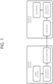
- FIG. 1 illustrates an example of a video/image coding system to which the embodiments of the present disclosure may be applied.
- a video/image coding system may include a first device (a source device) and a second device (a reception device).
- the source device may transmit encoded video/image information or data to the reception device through a digital storage medium or network in the form of a file or streaming.
- the source device may include a video source, an encoding apparatus, and a transmitter.
- the receiving device may include a receiver, a decoding apparatus, and a renderer.
- the encoding apparatus may be called a video/image encoding apparatus, and the decoding apparatus may be called a video/image decoding apparatus.
- the transmitter may be included in the encoding apparatus.
- the receiver may be included in the decoding apparatus.
- the renderer may include a display, and the display may be configured as a separate device or an external component.
- the encoding apparatus may encode input video/image.
- the encoding apparatus may perform a series of procedures such as prediction, transform, and quantization for compaction and coding efficiency.
- the encoded data (encoded video/image information) may be output in the form of a bitstream.
- the decoding apparatus may decode the video/image by performing a series of procedures such as dequantization, inverse transform, and prediction corresponding to the operation of the encoding apparatus.
- FIG. 2 is a diagram schematically illustrating the configuration of a video/image encoding apparatus to which the embodiments of the present disclosure may be applied.
- the video encoding apparatus may include an image encoding apparatus.
- the image partitioner 210, the predictor 220, the residual processor 230, the entropy encoder 240, the adder 250, and the filter 260 may be configured by one or more hardware components (e.g., encoder chipsets or processors) according to an embodiment.
- the memory 270 may include a decoded picture buffer (DPB), and may also be configured by a digital storage medium.
- the hardware component may further include the memory 270 as an internal/external component.
- the image partitioner 210 may split an input image (or, picture, frame) input to the encoding apparatus 200 into one or more processing units.
- the processing unit may be called a coding unit (CU).
- the coding unit may be recursively split according to a Quad-tree binary-tree ternary-tree (QTBTTT) structure from a coding tree unit (CTU) or the largest coding unit (LCU).
- QTBTTT Quad-tree binary-tree ternary-tree
- CTU coding tree unit
- LCU largest coding unit
- one coding unit may be split into a plurality of coding units of a deeper depth based on a quad-tree structure, a binary-tree structure, and/or a ternary-tree structure.
- an MxN block may represent samples composed of M columns and N rows or a group of transform coefficients.
- the sample may generally represent a pixel or a value of the pixel, and may also represent only the pixel/pixel value of a luma component, and also represent only the pixel/pixel value of a chroma component.
- the sample may be used as the term corresponding to a pixel or a pel configuring one picture (or image).
- the encoding apparatus 200 may subtract the prediction signal (predicted block, prediction sample array) output from the inter predictor 221 or the intra predictor 222 from the input image signal (original block, original sample array) to generate a residual signal (residual block, residual sample array), and the generated residual signal is transmitted to the transformer 232.
- a unit for subtracting the prediction signal (prediction block, prediction sample array) from an input image signal (original block, original sample array) in the encoder 200 may be referred to as a subtractor 231.
- the predictor 220 may perform prediction on a processing target block (hereinafter, referred to as a current block) and generate a predicted block including prediction samples for the current block.
- the predictor 220 may determine whether intra prediction or inter prediction is applied in units of a current block or CU.
- the predictor 220 may generate various information on prediction, such as prediction mode information, and transmit the generated information to the entropy encoder 240, as is described below in the description of each prediction mode.
- the information on prediction may be encoded by the entropy encoder 240 and output in the form of a bitstream.
- the intra predictor 222 may predict a current block with reference to samples within a current picture.
- the referenced samples may be located neighboring to the current block, or may also be located away from the current block according to the prediction mode.
- the prediction modes in the intra prediction may include a plurality of non-directional modes and a plurality of directional modes.
- the non-directional mode may include, for example, a DC mode or a planar mode.
- the directional mode may include, for example, 33 directional prediction modes or 65 directional prediction modes according to the fine degree of the prediction direction. However, this is illustrative and the directional prediction modes which are more or less than the above number may be used according to the setting.
- the intra predictor 222 may also determine the prediction mode applied to the current block using the prediction mode applied to the neighboring block.
- the inter predictor 221 may induce a predicted block of the current block based on a reference block (reference sample array) specified by a motion vector on a reference picture.
- the motion information may be predicted in units of a block, a sub-block, or a sample based on the correlation of the motion information between the neighboring block and the current block.
- the motion information may include a motion vector and a reference picture index.
- the motion information may further include inter prediction direction (L0 prediction, L1 prediction, Bi prediction, or the like) information.
- the neighboring block may include a spatial neighboring block existing within the current picture and a temporal neighboring block existing in the reference picture.
- the reference picture including the reference block and the reference picture including the temporal neighboring block may also be the same as each other, and may also be different from each other.
- the temporal neighboring block may be called the name such as a collocated reference block, a collocated CU (colCU), or the like, and the reference picture including the temporal neighboring block may also be called a collocated picture (colPic).
- the inter predictor 221 may configure a motion information candidate list based on the neighboring blocks, and generate information indicating what candidate is used to derive the motion vector and/or the reference picture index of the current block.
- the inter prediction may be performed based on various prediction modes, and for example, in the case of a skip mode and a merge mode, the inter predictor 221 may use the motion information of the neighboring block as the motion information of the current block. In the case of the skip mode, the residual signal may not be transmitted unlike the merge mode.
- a motion vector prediction (MVP) mode may indicate the motion vector of the current block by using the motion vector of the neighboring block as a motion vector predictor, and signaling a motion vector difference.
- MVP motion vector prediction
- the predictor 220 may generate a prediction signal based on various prediction methods to be described below.
- the predictor 220 may apply intra prediction or inter prediction for prediction of one block and may simultaneously apply intra prediction and inter prediction. This may be called combined inter and intra prediction (CIIP).
- the predictor may be based on an intra block copy (IBC) prediction mode or based on a palette mode for prediction of a block.
- the IBC prediction mode or the palette mode may be used for image/video coding of content such as games, for example, screen content coding (SCC).
- SCC screen content coding
- IBC basically performs prediction within the current picture, but may be performed similarly to inter prediction in that a reference block is derived within the current picture. That is, IBC may use at least one of the inter prediction techniques described in this document.
- the palette mode may be viewed as an example of intra coding or intra prediction. When the palette mode is applied, a sample value in the picture may be signaled based on information on the palette table and the palette index.
- the prediction signal generated by the predictor may be used to generate a reconstructed signal or may be used to generate a residual signal.
- the transformer 232 may generate transform coefficients by applying a transform technique to the residual signal.
- the transform technique may include at least one of a discrete cosine transform (DCT), a discrete sine transform (DST), a graph-based transform (GBT), or a conditionally non-linear transform (CNT).
- DCT discrete cosine transform
- DST discrete sine transform
- GBT graph-based transform
- CNT conditionally non-linear transform
- GBT refers to transformation obtained from a graph when expressing relationship information between pixels in the graph.
- CNT refers to transformation obtained based on a prediction signal generated using all previously reconstructed pixels.
- the transformation process may be applied to a block of pixels having the same size as a square or may be applied to a block of a variable size that is not a square.
- the quantizer 233 quantizes the transform coefficients and transmits the same to the entropy encoder 240, and the entropy encoder 240 encodes the quantized signal (information on the quantized transform coefficients) and outputs the encoded signal as a bitstream.
- Information on the quantized transform coefficients may be referred to as residual information.
- the quantizer 233 may rearrange the quantized transform coefficients in the block form into a one-dimensional vector form based on a coefficient scan order and may generate information on the transform coefficients based on the quantized transform coefficients in the one-dimensional vector form.
- the entropy encoder 240 may perform various encoding methods such as, for example, exponential Golomb, context-adaptive variable length coding (CAVLC), and context-adaptive binary arithmetic coding (CABAC).
- the entropy encoder 240 may encode information necessary for video/image reconstruction (e.g., values of syntax elements, etc.) other than the quantized transform coefficients together or separately.
- Encoded information e.g., encoded video/image information
- NAL network abstraction layer
- the video/image information may further include information on various parameter sets, such as an adaptation parameter set (APS), a picture parameter set (PPS), a sequence parameter set (SPS), or a video parameter set (VPS). Also, the video/image information may further include general constraint information.
- APS adaptation parameter set
- PPS picture parameter set
- SPS sequence parameter set
- VPS video parameter set
- the video/image information may further include general constraint information.
- information and/or syntax elements transmitted/signaled from the encoding apparatus to the decoding apparatus may be included in video/image information.
- the video/image information may be encoded through the encoding procedure described above and included in the bitstream.
- the bitstream may be transmitted through a network or may be stored in a digital storage medium.
- the network may include a broadcasting network and/or a communication network
- the digital storage medium may include various storage media such as USB, SD, CD, DVD, Blu-ray, HDD, and SSD.
- a transmitting unit (not shown) and/or a storing unit (not shown) for transmitting or storing a signal output from the entropy encoder 240 may be configured as internal/external elements of the encoding apparatus 200, or the transmitting unit may be included in the entropy encoder 240.
- the quantized transform coefficients output from the quantizer 233 may be used to generate a prediction signal.
- the residual signal residual block or residual samples
- the adder 250 may add the reconstructed residual signal to the prediction signal output from the inter predictor 221 or the intra predictor 222 to generate a reconstructed signal (reconstructed picture, reconstructed block, reconstructed sample array).
- the predicted block may be used as a reconstructed block.
- the adder 250 may be referred to as a restoration unit or a restoration block generator.
- the generated reconstructed signal may be used for intra prediction of a next processing target block in the current picture, or may be used for inter prediction of the next picture after being filtered as described below.
- LMCS luma mapping with chroma scaling
- the filter 260 may improve subjective/objective image quality by applying filtering to the reconstructed signal.
- the filter 260 may generate a modified reconstructed picture by applying various filtering methods to the reconstructed picture, and store the modified reconstructed picture in the memory 270, specifically, in a DPB of the memory 270.
- the various filtering methods may include, for example, deblocking filtering, a sample adaptive offset, an adaptive loop filter, a bilateral filter, and the like.
- the filter 260 may generate various kinds of information related to the filtering, and transfer the generated information to the entropy encoder 240 as described later in the description of each filtering method.
- the information related to the filtering may be encoded by the entropy encoder 240 and output in the form of a bitstream.
- the modified reconstructed picture transmitted to the memory 270 may be used as a reference picture in the inter predictor 221.
- inter prediction When the inter prediction is applied through the encoding apparatus, prediction mismatch between the encoding apparatus 200 and the decoding apparatus may be avoided and encoding efficiency may be improved.
- the DPB of the memory 270 may store the modified reconstructed picture for use as the reference picture in the inter predictor 221.
- the memory 270 may store motion information of a block from which the motion information in the current picture is derived (or encoded) and/or motion information of blocks in the picture, having already been reconstructed.
- the stored motion information may be transferred to the inter predictor 221 to be utilized as motion information of the spatial neighboring block or motion information of the temporal neighboring block.
- the memory 270 may store reconstructed samples of reconstructed blocks in the current picture, and may transfer the reconstructed samples to the intra predictor 222.
- FIG. 3 is a diagram for schematically explaining the configuration of a video/image decoding apparatus to which the embodiments of the present disclosure may be applied.
- the decoding apparatus 300 may include and configured with an entropy decoder 310, a residual processor 320, a predictor 330, an adder 340, a filter 350, and a memory 360.
- the predictor 330 may include an inter predictor 331 and an intra predictor 332.
- the residual processor 320 may include a dequantizer 321 and an inverse transformer 322.
- the entropy decoder 310, the residual processor 320, the predictor 330, the adder 340, and the filter 350 which have been described above, may be configured by one or more hardware components (e.g., decoder chipsets or processors) according to an embodiment.
- the memory 360 may include a decoded picture buffer (DPB), and may be configured by a digital storage medium.
- the hardware component may further include the memory 360 as an internal/external component.
- the decoding apparatus 300 may reconstruct the image in response to a process in which the video/image information is processed in the encoding apparatus illustrated in FIG. 2 .
- the decoding apparatus 300 may derive the units/blocks based on block split-related information acquired from the bitstream.
- the decoding apparatus 300 may perform decoding using the processing unit applied to the encoding apparatus. Therefore, the processing unit for the decoding may be, for example, a coding unit, and the coding unit may be split according to the quad-tree structure, the binary-tree structure, and/or the ternary-tree structure from the coding tree unit or the maximum coding unit.
- One or more transform units may be derived from the coding unit.
- the reconstructed image signal decoded and output through the decoding apparatus 300 may be reproduced through a reproducing apparatus.
- the decoding apparatus 300 may receive a signal output from the encoding apparatus of Figure 2 in the form of a bitstream, and the received signal may be decoded through the entropy decoder 310.
- the entropy decoder 310 may parse the bitstream to derive information (e.g., video/image information) necessary for image reconstruction (or picture reconstruction).
- the video/image information may further include information on various parameter sets such as an adaptation parameter set (APS), a picture parameter set (PPS), a sequence parameter set (SPS), or a video parameter set (VPS).
- the video/image information may further include general constraint information.
- the decoding apparatus may further decode picture based on the information on the parameter set and/or the general constraint information.
- Signaled/received information and/or syntax elements described later in this document may be decoded may decode the decoding procedure and obtained from the bitstream.
- the entropy decoder 310 decodes the information in the bitstream based on a coding method such as exponential Golomb coding, context-adaptive variable length coding (CAVLC), or context-adaptive arithmetic coding (CABAC), and output syntax elements required for image reconstruction and quantized values of transform coefficients for residual.
- a coding method such as exponential Golomb coding, context-adaptive variable length coding (CAVLC), or context-adaptive arithmetic coding (CABAC)
- the CABAC entropy decoding method may receive a bin corresponding to each syntax element in the bitstream, determine a context model by using a decoding target syntax element information, decoding information of a decoding target block or information of a symbol/bin decoded in a previous stage, and perform an arithmetic decoding on the bin by predicting a probability of occurrence of a bin according to the determined context model, and generate a symbol corresponding to the value of each syntax element.
- the CABAC entropy decoding method may update the context model by using the information of the decoded symbol/bin for a context model of a next symbol/bin after determining the context model.
- the information related to the prediction among the information decoded by the entropy decoder 310 may be provided to the predictor (inter predictor 332 and intra predictor 331), and residual values on which the entropy decoding has been performed in the entropy decoder 310, that is, the quantized transform coefficients and related parameter information, may be input to the residual processor 320.
- the residual processor 320 may derive a residual signal (residual block, residual samples, and residual sample array). Also, information on filtering among the information decoded by the entropy decoder 310 may be provided to the filter 350. Meanwhile, a receiving unit (not shown) for receiving a signal output from the encoding apparatus may be further configured as an internal/external element of the decoding apparatus 300, or the receiving unit may be a component of the entropy decoder 310. Meanwhile, the decoding apparatus according to this document may be called a video/image/picture decoding apparatus, and the decoding apparatus may be divided into an information decoder (video/image/picture information decoder) and a sample decoder (video/image/picture sample decoder).
- the information decoder may include the entropy decoder 310, and the sample decoder may include at least one of the dequantizer 321, the inverse transformer 322, the adder 340, the filter 350, the memory 360, an inter predictor 332, and an intra predictor 331.
- the dequantizer 321 may dequantize the quantized transform coefficients to output the transform coefficients.
- the dequantizer 321 may rearrange the quantized transform coefficients in a two-dimensional block form. In this case, the rearrangement may be performed based on a coefficient scan order performed by the encoding apparatus.
- the dequantizer 321 may perform dequantization for the quantized transform coefficients using a quantization parameter (e.g., quantization step size information), and acquire the transform coefficients.
- a quantization parameter e.g., quantization step size information
- the inverse transformer 322 inversely transforms the transform coefficients to acquire the residual signal (residual block, residual sample array).
- the predictor 330 may perform the prediction of the current block, and generate a predicted block including the prediction samples of the current block.
- the predictor may determine whether the intra prediction is applied or the inter prediction is applied to the current block based on the information on prediction output from the entropy decoder 310, and determine a specific intra/inter prediction mode.
- the predictor 330 may generate a prediction signal based on various prediction methods to be described later.
- the predictor may apply intra prediction or inter prediction for prediction of one block, and may simultaneously apply intra prediction and inter prediction. This may be called combined inter and intra prediction (CIIP).
- the predictor may be based on an intra block copy (IBC) prediction mode or based on a palette mode for prediction of a block.
- the IBC prediction mode or the palette mode may be used for image/video coding of content such as games, for example, screen content coding (SCC).
- SCC screen content coding
- IBC may basically perform prediction within the current picture, but may be performed similarly to inter prediction in that a reference block is derived within the current picture. That is, IBC may use at least one of the inter prediction techniques described in this document.
- the palette mode may be considered as an example of intra coding or intra prediction. When the palette mode is applied, information on the palette table and the palette index may be included in the video/image information and signaled.
- the intra predictor 331 may predict the current block by referring to the samples in the current picture.
- the referred samples may be located in the neighborhood of the current block, or may be located apart from the current block according to the prediction mode.
- prediction modes may include a plurality of non-directional modes and a plurality of directional modes.
- the intra predictor 331 may determine the prediction mode to be applied to the current block by using the prediction mode applied to the neighboring block.
- the inter predictor 332 may derive a predicted block for the current block based on a reference block (reference sample array) specified by a motion vector on a reference picture.
- motion information may be predicted in the unit of blocks, subblocks, or samples based on correlation of motion information between the neighboring block and the current block.
- the motion information may include a motion vector and a reference picture index.
- the motion information may further include information on inter prediction direction (L0 prediction, L1 prediction, Bi prediction, and the like).
- the neighboring block may include a spatial neighboring block existing in the current picture and a temporal neighboring block existing in the reference picture.
- the inter predictor 332 may construct a motion information candidate list based on neighboring blocks, and derive a motion vector of the current block and/or a reference picture index based on the received candidate selection information.
- Inter prediction may be performed based on various prediction modes, and the information on the prediction may include information indicating a mode of inter prediction for the current block.
- the adder 340 may generate a reconstructed signal (reconstructed picture, reconstructed block, or reconstructed sample array) by adding the obtained residual signal to the prediction signal (predicted block or predicted sample array) output from the predictor (including inter predictor 332 and/or intra predictor 331). If there is no residual for the processing target block, such as a case that a skip mode is applied, the predicted block may be used as the reconstructed block.
- the adder 340 may be called a reconstructor or a reconstructed block generator.
- the generated reconstructed signal may be used for the intra prediction of a next block to be processed in the current picture, and as described later, may also be output through filtering or may also be used for the inter prediction of a next picture.
- LMCS luma mapping with chroma scaling
- the filter 350 may improve subjective/objective image quality by applying filtering to the reconstructed signal.
- the filter 350 may generate a modified reconstructed picture by applying various filtering methods to the reconstructed picture, and store the modified reconstructed picture in the memory 360, specifically, in a DPB of the memory 360.
- the various filtering methods may include, for example, deblocking filtering, a sample adaptive offset, an adaptive loop filter, a bilateral filter, and the like.
- the (modified) reconstructed picture stored in the DPB of the memory 360 may be used as a reference picture in the inter predictor 332.
- the memory 360 may store the motion information of the block from which the motion information in the current picture is derived (or decoded) and/or the motion information of the blocks in the picture having already been reconstructed.
- the stored motion information may be transferred to the inter predictor 332 so as to be utilized as the motion information of the spatial neighboring block or the motion information of the temporal neighboring block.
- the memory 360 may store reconstructed samples of reconstructed blocks in the current picture, and transfer the reconstructed samples to the intra predictor 331.
- the embodiments described in the filter 260, the inter predictor 221, and the intra predictor 222 of the encoding apparatus 200 may be applied equally or to correspond to the filter 350, the inter predictor 332, and the intra predictor 331.
- the video/image coding method may be performed based on the following partitioning structure. Specifically, procedures of prediction, residual processing ((inverse) transform and (de)quantization), syntax element coding, and filtering to be described later may be performed based on CTU and CU (and/or TU and PU) derived based on the partitioning structure.
- a block partitioning procedure may be performed by the image partitioner 210 of the above-described encoding apparatus, and partitioning related information may be processed (encoded) by the entropy encoder 240, and may be transferred to the decoding apparatus in the form of a bitstream.
- the entropy decoder 310 of the decoding apparatus may derive the block partitioning structure of the current picture based on the partitioning related information obtained from the bitstream, and based on this, may perform a series of procedures for image decoding (e.g., prediction, residual processing, block/picture reconstruction, and in-loop filtering).
- the CU size and the TU size may be equal to each other, or a plurality of TUs may be present in the CU area.
- the CU size may generally represent a luma component (sample) coding block (CB) size.
- the TU size may generally represent a luma component (sample) transform block (TB) size.
- a chroma component (sample) CB or TB size may be derived based on the luma component (sample) CB or TB size in accordance with a component ratio according to a color format (chroma format, e.g., 4:4:4, 4:2:2, 4:2:0, and the like) of the picture/image.
- the TU size may be derived based on maxTbSize. For example, if the CU size is larger than the maxTbSize, a plurality of TUs (TBs) of the maxTbSize may be derived, and the transform / inverse transform may be performed in the unit of the TU (TB).
- the intra prediction mode/type may be derived in the unit of CU (or CB), and the derivation of a neighboring reference sample and the generation of a prediction sample may be performed in the unit of TU (or TB).
- the intra prediction mode/type may be derived in the unit of CU (or CB), and the derivation of a neighboring reference sample and the generation of a prediction sample may be performed in the unit of TU (or TB).
- one or a plurality of TUs (or TBs) may be present in one CU (or CB) area, and in this case, the plurality of TUs (or TBs) may share the same intra prediction mode/type.
- the image processing unit may have a hierarchical structure.
- One picture may be divided into one or more tiles, bricks, slices, and/or tile groups.
- One slice may include one or more bricks.
- One brick may include one or more CTU rows in a tile.
- the slice may include an integer number of bricks of the picture.
- One tile group may include one or more tiles.
- One tile is a rectangular region of CTUs within a particular tile column and a particular tile row in a picture.
- the tile group may include an integer number of tiles in accordance with the tile raster scan in the picture.
- a slice header may carry information/parameters that can be applied to the corresponding slice (blocks in the slice).
- the encoding/decoding procedures for the tile, slice, brick, and/or tile group may be processed in parallel.
- the slice or the tile group may be interchangeably used. That is, the tile group header may be called a slice header.
- the slice may have one of slice types including an intra (I) slice, a predictive (P) slice, and a bi-predictive (B) slice.
- I intra
- P predictive
- B bi-predictive
- the inter prediction may not be used, but only the intra prediction may be used. Even in this case, the original sample value may be coded and signaled without the prediction.
- the intra prediction or the inter prediction may be used, and in case of using the inter prediction, only uni-prediction may be used.
- the intra prediction or the inter prediction may be used, and in case of using the inter prediction, maximally up to bi-prediction may be used.
- the encoder may determine the tile / tile group, brick, slice, maximum and minimum coding unit sizes, and corresponding information or information capable of inducing the same may be included in the bitstream.
- the decoder may obtain information representing whether the tile / tile group, brick, slice, or CTU in the tile of the current picture has been partitioned into a plurality of coding units. By obtaining (transmitting) such information only under a specific condition, the efficiency can be enhanced.
- Pictures may be divided into sequences of coding tree units (CTUs).
- the CTU may correspond to a coding tree block (CTB).
- CTU may include a coding tree block of luma samples, and two coding tree blocks of corresponding chroma samples.
- the CTU may include an NxN block of the luma samples and two corresponding blocks of the chroma samples.
- the CTU may be divided into CUs based on a quad-tree (QT) structure.
- the quad-tree structure may be called a quaternary tree structure. This is to reflect various local characteristics.
- the CTU may be divided based on splitting of the multi-type tree structure including not only a quad-tree but also a binary-tree (BT) and a ternary-tree (TT).
- BT binary-tree
- TT ternary-tree
- a QTBT structure may include a splitting structure based on the quad-tree and the binary-tree
- a QTBTTT may include a splitting structure based on the quad-tree, the binary-tree, and the ternary-tree.
- the QTBT structure may include a splitting structure based on the quad-tree, the binary-tree, and the ternary-tree.
- the CU may have a square or rectangular shape.
- the CTU may be first split into the quad-tree structure. Thereafter, leaf nodes of the quad-tree structure may be further split by the multi-type tree structure. For example, schematically four splitting types may be included in the multi-type tree structure.
- the four splitting types may include vertical binary splitting (SPLIT_BT_VER), horizontal binary splitting (SPLIT_BT_HOR), vertical ternary splitting (SPLIT_TT_VER), and horizontal ternary splitting (SPLIT_TT_HOR).
- the leaf nodes of the multi-type tree structure may be called CUs.
- Such CUs may be used for the prediction and transform procedure.
- the CU, PU, and TU may generally have the same block size. However, if the maximum supported transform length is smaller than the width or height of a color component of the CU, the CU and the TU may have different block sizes.
- one picture may include a plurality of slices, and one slice may include a slice header and slice data.
- one picture header may be further added for the plurality of slices (set of the slice header and slice data) in one picture.
- the picture header may include information/parameters capable of being commonly applied to the picture.
- the slice header (slice header syntax) may include information/parameters capable of being commonly applied to the slice.
- An adaptation parameter set (APS) or a picture parameter set (PPS) may include information/parameters capable of being commonly applied to one or more pictures.
- a sequence parameter set (SPS) may include information/parameters capable of being commonly applied to one or more sequences.
- a video parameter set may include information/parameters capable of being commonly applied to multiple layers.
- a decoding parameter set may include information/parameters capable of being commonly applied to the overall video.
- the DPS may include information/parameters related to concatenation of a coded video sequence (CVS).
- an upper layer syntax may include at least one of the APS syntax, PPS syntax, SPS syntax, VPS syntax, DPS syntax, picture header syntax, and slice header syntax.
- information on the division and the configuration of the tile / tile group / brick / slice may be configured by the encoding end through the upper level syntax, and may be transferred to the decoding apparatus in the form of a bitstream.
- At least one of quantization/dequantization and/or transform/inverse transform may be omitted.
- the quantized transform coefficient may be referred to as a transform coefficient.
- the transform coefficient may be called a coefficient or a residual coefficient or may still be called the transform coefficient for uniformity of expression.
- the quantized transform coefficient and the transform coefficient may be referred to as a transform coefficient and a scaled transform coefficient, respectively.
- the residual information may include information on transform coefficient(s), and the information on the transform coefficient(s) may be signaled through residual coding syntax.
- Transform coefficients may be derived based on the residual information (or information on the transform coefficient(s)), and scaled transform coefficients may be derived through inverse transform (scaling) on the transform coefficients.
- Residual samples may be derived based on inverse transform (transform) of the scaled transform coefficients. This may be applied/expressed in other parts of the present document as well.
- the encoding apparatus may perform various encoding methods, for example, such as exponential Golomb, context-adaptive variable length coding (CAVLC), and context-adaptive binary arithmetic coding (CABAC). Further, the decoding apparatus may decode information in the bitstream based on the coding method, such as the exponential Golomb, CAVLC, or CABAC, and may output a value of a syntax element and quantized values of transform coefficients for residual, being necessary for image reconstruction. For example, the above-described coding methods may be performed as in the contents to be described later.
- the intra prediction may represent the prediction that generates the prediction samples for the current block based on the reference samples in the picture (hereinafter, current picture) to which the current block belongs.
- the neighboring reference samples to be used for the intra prediction of the current block may be derived.
- the neighboring reference samples of the current block may include a sample adjacent to the left boundary of the current block having the size of nWxnH and total 2xnH samples neighboring the bottom-left, a sample adjacent to the top boundary of the current block and total 2xnW samples neighboring the top-right, and one sample neighboring the top-left of the current block.
- the neighboring reference samples of the current block may include a plurality of columns of top neighboring samples and a plurality of rows of left neighboring samples. Further, the neighboring reference samples of the current block may include total nH samples adjacent to the right boundary of the current block having the size of nWxnH, total nW samples adjacent to the bottom boundary of the current block, and one sample neighboring the bottom-right of the current block.
- the decoding apparatus may configure the neighboring reference samples to be used for the prediction through substation of enabled samples for non-enabled sample. Further, the neighboring reference samples to be used for the prediction may be configured through interpolation of the enabled samples.
- the prediction sample may be induced based on an average or interpolation of the neighboring reference samples of the current block, and (ii) the prediction sample may be induced based on the reference sample that is present in a specific (prediction) direction for the prediction sample among the neighboring reference samples of the current block.
- the case of (i) may be called a non-directional mode or a non-angular mode, and the case of (ii) may be called a directional mode or an angular mode.
- the prediction sample may be generated through interpolation of the first neighboring sample with the second neighboring sample located in an opposite direction to the prediction direction of the intra prediction mode of the current block based on the prediction sample of the current block among the neighboring reference samples.
- LIP linear interpolation intra prediction
- chroma prediction samples may be generated based on luma samples using a linear model. This case may be called an LM mode.
- a temporary prediction sample of the current block may be derived based on the filtered neighboring reference samples, and a prediction sample of the current block may be derived by calculating a weighted sum of the temporary prediction sample and at least one reference sample derived in accordance with the intra prediction mode among the existing neighboring reference samples, that is, non-filtered neighboring reference samples.
- the above-described case may be called a position dependent intra prediction (PDPC).
- the prediction sample may be derived using a reference sample located in a prediction direction on a reference sample line having the highest prediction accuracy among neighboring multiple reference sample lines of the current block through selection of the corresponding line, and in this case, intra prediction coding may be performed in a method for indicating (signaling) the used reference sample line to the decoding apparatus.
- the above-described case may be called multi-reference line (MRL) intra prediction or MRL-based intra prediction.
- the intra prediction may be performed based on the same intra prediction mode through division of the current block into vertical or horizontal subpartitions, and the neighboring reference samples may be derived and used in the unit of a subpartition. That is, in this case, since the intra prediction mode for the current block is equally applied to the subpartitions, and the neighboring reference samples are derived and used in the unit of the subpartition, the intra prediction performance can be enhanced in some cases.
- Such a prediction method may be called intra subpartitions (ISP) or ISP-based intra prediction.
- ISP intra subpartitions
- ISP intra subpartitions
- the above-described intra prediction method may be called the intra prediction type in distinction from the intra prediction mode.
- the intra prediction type may be called by various terms, such as an intra prediction technique or an additional intra prediction mode.
- the intra prediction type (or additional intra prediction mode) may include at least one of LIP, PDPC, MRL, or ISP described above.
- a general intra prediction method excluding a specific intra prediction type, such as the LIP, PDPC, MRL, or ISP, may be called a normal intra prediction type.
- the normal intra prediction type may be generally applied in case that the specific intra prediction type is not applied, and the prediction may be performed based on the above-described intra prediction mode. Meanwhile, as needed, post-filtering for the derived prediction sample may be performed.
- the intra prediction procedure may include steps of intra prediction mode/type determination, neighboring reference sample derivation, and intra prediction mode/type-based prediction sample derivation. Further, as needed, a post-filtering step for the derived prediction sample may be performed.
- an affine linear weighted intra prediction may be used.
- the ALWIP may be called linear weighted intra prediction (LWIP) or matrix weighted intra prediction (MIP) or matrix based intra prediction.
- LWIP linear weighted intra prediction
- MIP matrix weighted intra prediction
- the prediction samples for the current block may be derived by further performing a horizontal/vertical interpolation.
- the intra prediction modes being used for the MIP may be configured differently from the above-described LIP, PDPC, MRL, or ISP intra prediction, or the intra prediction modes being used for the normal intra prediction.
- the intra prediction mode for the MIP may be called an MIP intra prediction mode, an MIP prediction mode, or an MIP mode.
- a matrix and an offset being used for the matrix vector multiplication may be differently configured.
- the matrix may be called an (MIP) weighted matrix
- the offset may be called an (MIP) offset vector or an (MIP) bias vector.
- the intra prediction based video/image encoding procedure may include the followings.
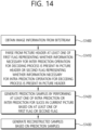
- FIG. 4 illustrates an example of a video/image encoding method based on intra prediction
- FIG. 5 schematically illustrates an intra predictor in an encoding apparatus.
- S400 may be performed by the intra predictor 222 of the encoding apparatus, and S410 to S430 may be performed by the residual processor 230 of the encoding apparatus.
- S410 may be performed by the subtractor 231 of the encoding apparatus
- S420 may be performed by the transformer 232 and the quantizer 233 of the encoding apparatus
- S430 may be performed by the dequantizer 234 and the inverse transformer 235 of the encoding apparatus.
- prediction information may be derived by the intra predictor 222, and may be encoded by the entropy encoder 240.
- residual information may be derived, and may be encoded by the entropy encoder 240.
- the residual information is information about the residual samples.
- the residual information may include information about the quantized transform coefficients for the residual samples.
- the residual samples may be derived as transform coefficients through the transformer 232 of the encoding apparatus, and the transform coefficients may be derived as the quantized transform coefficients through the quantizer 233.
- the information about the quantized transform coefficients may be encoded by the entropy encoder 240 through the residual coding procedure.
- the encoding apparatus performs intra prediction for the current block (S400).
- the encoding apparatus may derive an intra prediction mode for the current block, derive neighboring reference samples of the current block, and generate prediction samples in the current block based on the intra prediction mode and the neighboring reference samples.
- the procedures of determining the intra prediction mode, deriving the neighboring reference samples, and generating the prediction samples may be simultaneously performed, and any one procedure may be performed prior to another procedure.
- the intra predictor 222 of the encoding apparatus may include a prediction mode/type determiner 222_1, a reference sample deriver 222_2, and a prediction sample deriver 222_3, and the prediction mode/type determiner 222_1 may determine the intra prediction mode/type for the current block, the reference sample deriver 222_2 may derive the neighboring reference samples of the current block, and the prediction sample deriver 222_3 may derive motion samples of the current block. Meanwhile, in case that a prediction sample filtering procedure to be described later is performed, the intra predictor 222 may further include a prediction sample filter (not illustrated).
- the encoding apparatus may determine a mode being applied for the current block among a plurality of intra prediction modes. The encoding apparatus may compare RD costs for the intra prediction modes, and may determine the optimum intra prediction mode for the current block.
- the encoding apparatus may perform the prediction sample filtering procedure.
- the prediction sample filtering may be called post-filtering. Some or all of the prediction samples may be filtered by the prediction sample filtering procedure. In some cases, the prediction sample filtering procedure may be omitted.
- the encoding apparatus derives residual samples for the current block based on the prediction samples (S410).
- the encoding apparatus may compare the prediction samples with the original samples of the current block based on phase, and may derive the residual samples.
- the encoding apparatus may derive quantized transform coefficients through transform/quantization of the residual samples (S420), and then may derive the (modified) residual samples by performing the dequantization / inverse transform of the quantized transform coefficients again (S430).
- the reason why to perform the dequantization / inverse transform again after the transform/quantization is to derive the same residual samples as the residual samples being derived by the decoding apparatus as described above.
- the encoding apparatus may generate a reconstructed block including reconstructed samples for the current block based on the prediction samples and the (modified) residual samples (S440). Based on the reconstructed block a reconstructed picture for the current picture may be generated.
- the encoding apparatus may encode image information including prediction information on the intra prediction (e.g., prediction mode information representing the prediction mode) and the residual information on the intra/residual samples, and may output the encoded image information in the form of the bitstream.
- the residual information may include a residual coding syntax.
- the encoding apparatus may derive quantized transform coefficients through transform/quantization of the residual samples.
- the residual information may include information on the quantized transform coefficients.
- the intra prediction based video/image decoding procedure may include the followings.
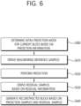
- FIG. 6 illustrates an example of a video/image decoding method based on intra prediction
- FIG. 7 schematically illustrates an intra predictor in a decoding apparatus.
- the decoding apparatus may perform an operation corresponding to the operation performed by the encoding apparatus.
- S600 to 610 may be performed by the intra predictor 331 of the decoding apparatus, and prediction information of S600 and residual information of S630 may be obtained from a bitstream by the entropy decoder 310 of the decoding apparatus.
- the residual processor 320 of the decoding apparatus may derive residual samples for the current block based on the residual information.
- the dequantizer 321 of the residual processor 320 may derive transform coefficients by performing dequantization based on the quantized transform coefficients derived based on the residual information
- the inverse transformer 322 of the residual processor may derive the residual samples for the current block by performing dequantization for the transform coefficients.
- S640 may be performed by the adder 340 or the reconstructor of the decoding apparatus.
- the decoding apparatus may derive the intra prediction mode for the current block based on the received prediction information (S600).
- the decoding apparatus may derive neighboring reference samples of the current block (S610).
- the decoding apparatus generates prediction samples in the current block by performing the intra prediction based on the intra prediction mode and the neighboring reference samples (S620).
- the decoding apparatus may perform the prediction sample filtering procedure.
- the prediction sample filtering may be called post-filtering. Some or all of the prediction samples may be filtered by the prediction sample filtering procedure. In some cases, the prediction sample filtering procedure may be omitted.
- the decoding apparatus generates the residual samples for the current block based on the received residual information (S630).
- the decoding apparatus may generate reconstructed samples for the current block based on the prediction samples and the residual samples, and may derive a reconstructed block including the reconstructed samples (S640).
- a reconstructed picture for the current picture may be generated based on the reconstructed block.
- the intra predictor 331 of the decoding apparatus may include a prediction mode/type determiner 331_1, a reference sample deriver 331_2, and a prediction sample deriver 331_3.
- the prediction mode/type determiner 331_1 may determine the intra prediction mode for the current block based on prediction mode information obtained by the entropy decoder 310 of the decoding apparatus, the reference sample deriver 331_2 may derive the neighboring reference samples of the current block, and the prediction sample deriver 331_3 may derive the prediction sample of the current block.
- the intra predictor 331 may further include a prediction sample filter (not illustrated).
- the prediction information may include intra prediction mode information and/or intra prediction type information.
- the intra prediction mode information may include flag information (e.g., intra_luma_mpm_flag) representing whether a most probable mode (MPM) or a remaining mode is applied to the current block, and in case that the MPM is applied to the current block, the prediction mode information may further include index information (e.g., intra_luma_mpm_idx) representing one of intra prediction mode candidates (MPM candidates).
- MPM candidates may constitute an MPM candidate list or an MPM list.
- the intra prediction mode information may further include remaining mode information (e.g., intra_luma_mpm_remainder) indicating one of remaining intra prediction modes excluding the intra prediction mode candidates (MPM candidates).
- the decoding apparatus may determine the intra prediction mode of the current block based on the intra prediction mode information. For the above-described MIP, a separate MPM list may be configured.
- the intra prediction type information may be implemented in various forms.
- the intra prediction type information may include intra prediction type index information indicating one of the intra prediction types.
- the intra prediction type information may include at least one of reference sample line information (e.g., intra_luma_ref_idex) representing whether the MRL is applied to the current block and which reference sample line is used in case that the MRL is applied, ISP flag information (e.g., intra_subpartitions_mode_flag) representing whether the ISP is applied to the current block, ISP type information (e.g., intra_subpartitions_split_flag) indicating the partitioning type of subpartitions in case that the ISP is applied, flag information representing whether the PDCP is applied, or flag information representing whether the LIP is applied.
- the intra prediction type information may include an MIP flag representing whether the MIP is applied to the current block.
- the intra prediction mode information and/or the intra prediction type information may be encoded/decoded through the coding method described in the present document.
- the intra prediction mode information and/or the intra prediction type information may be encoded/decoded through entropy coding (e.g., CABAC or CAVLC) based on a truncated (rice) binary code.
- entropy coding e.g., CABAC or CAVLC
- the video/image encoding procedure based on the inter prediction may include the followings.
- FIG. 8 illustrates an example of video/image encoding method based on inter prediction
- FIG. 9 schematically illustrates an inter predictor in an encoding apparatus.
- the encoding apparatus performs inter prediction for the current block (S800).
- the encoding apparatus may derive an inter prediction mode and motion information of the current block, and may generate prediction samples of the current block.
- the procedures of determining the inter prediction mode, deriving motion information, and generating the prediction samples may be performed simultaneously, and any one procedure may be performed prior to another procedure.
- the inter predictor 221 of the encoding apparatus may include a prediction mode determiner 221_1, a motion information deriver 221_2, and a prediction sample deriver 221_3, and the prediction mode determiner 221_1 may determine the prediction mode for the current block, the motion information deriver 221_2 may derive the motion information of the current block, and the prediction sample deriver 221_3 may derive the prediction samples for the current block.
- the inter predictor of the encoding apparatus may search a block similar to the current block in a specific area (search area) of the reference pictures through motion estimation, and may derive the reference block having a difference from the current block that is the minimum or equal to or lower than a predetermined level.
- a reference picture index indicating a reference picture in which the reference block is located is derived, and a motion vector is derived based on a difference in location between the reference block and the current block.
- the encoding apparatus may determine a mode being applied for the current block among various prediction modes.
- the encoding apparatus may compare rate-distortion (RD) costs for the various prediction modes, and may determine the optimum prediction mode for the current block.
- RD rate-distortion
- the encoding apparatus may configure a merge candidate list, and may derive the reference block having the difference from the current block that is the minimum or equal to or lower than the predetermined level among the reference blocks indicated by the merge candidates included in the merge candidate list.
- a merge candidate related to the derived reference block may be selected, and merge index information indicating the selected merge candidate may be generated and signaled to the decoding apparatus.
- the motion information of the current block may be derived by using the motion information of the selected merge candidate.
- the encoding apparatus may configure an (A)MVP candidate list, and may use the motion vector of the mvp candidate selected among motion vector predictor (mvp) candidates included in the (A)MVP candidate list as the mvp of the current block.
- the motion vector indicating the reference block derived by the above-described motion estimation may be used as the motion vector of the current block, and the mvp candidate having the motion vector having the smallest difference from the motion vector of the current block among the mvp candidates may be the selected mvp candidate.
- a motion vector difference which is the difference obtained by subtracting the mvp from the motion vector of the current block, may be derived.
- information on the MVD may be signaled to the decoding apparatus.
- the value of the reference picture index may be configured as the reference picture index information, and may be separately signaled to the decoding apparatus.
- the encoding apparatus may derive residual samples based on the prediction samples (S810).
- the encoding apparatus may derive the residual samples through comparison of the prediction samples with the original samples of the current block.
- the encoding apparatus encodes image information including prediction information and residual information (S820).
- the encoding apparatus may output the encoded image information in the form of a bitstream.
- the prediction information may be information related to the prediction procedure, and may include information related to the prediction mode information (e.g., skip flag, merge flag, or mode index) and the motion information.
- the information about the motion information may include candidate selection information (e.g., merge index, mvp flag, or mvp index) that is the information for deriving the motion vector.
- the information about the motion information may include information about the above-described MVD and/or the reference picture index information.
- the information about the motion information may include information representing whether L0 prediction, L1 prediction, or bi-prediction is applied.
- the residual information is information about the residual samples.
- the residual information may include information about quantized transform coefficients for the residual samples.
- the output bitstream may be stored in a (digital) storage medium to be transferred to the decoding apparatus, or may be transferred to the decoding apparatus through a network.
- the encoding apparatus may generate a reconstructed picture (including reconstructed samples and reconstructed block) based on the reference samples and the residual samples. This is for the encoding apparatus to derive the same prediction result as that performed in the decoding apparatus, and through this, the coding efficiency can be enhanced. Accordingly, the encoding apparatus may store the reconstructed picture (or reconstructed samples or reconstructed block) in a memory, and may utilize the same as a reference picture for the inter prediction. As described above, an in-loop filtering procedure may be further applied to the reconstructed picture.
- a video/image decoding procedure based on inter prediction may include the followings.
- FIG. 10 illustrates an example of a video/image decoding method based on inter prediction
- FIG. 11 schematically illustrates an inter predictor in a decoding apparatus.
- the decoding apparatus may perform an operation corresponding to the operation performed by the encoding apparatus.
- the decoding apparatus may perform prediction for the current block based on the received prediction information, and may derive prediction samples.
- the decoding apparatus may determine a prediction mode for the current block based on prediction information received from a bitstream (S1000).
- the decoding apparatus may determine which inter prediction mode is applied to the current block based on prediction mode information in the prediction information.
- inter prediction mode candidates may include various inter prediction modes, such as a skip mode, a merge mode, and/or an (A)MVP mode.
- the decoding apparatus derives motion information of the current block based on the determined inter prediction mode (S1010). For example, in case that a skip mode or a merge mode is applied to the current block, the decoding apparatus may configure a merge candidate list to be described later, and may select one of merge candidates included in the merge candidate list. The selection may be performed based on the above-described selection information (merge index).
- the motion information of the current block may be derived by using the motion information of the selected merge candidate.
- the motion information of the selected merge candidate may be used as the motion information of the current block.
- the decoding apparatus may configure the (A)MVP candidate list, and may use the motion vector of the mvp candidate selected among the motion vector predictor (mvp) candidates included in the (A)MVP candidate list.
- the selection may be performed based on the above-described selection information (mvp flag or mvp index).
- the MVD of the current block may be derived based on information on the MVD
- the motion vector of the current block may be derived based on the mvp and the MVD of the current block.
- the reference picture index of the current block may be derived based on the reference picture index information.
- the picture indicated by the reference picture index in the reference picture list for the current block may be derived as the reference picture being referred to for the inter prediction of the current block.
- the motion information of the current block may be derived without the candidate list configuration, and in this case, the above-described candidate list configuration may be omitted.
- the decoding apparatus may generate prediction samples for the current block based on the motion information of the current block (S 1020).
- the reference picture may be derived based on the reference picture index of the current block, and the motion vector of the current block may derive the prediction samples of the current block by using samples of the reference block indicated in the reference picture.
- the prediction sample filtering procedure may be further performed for all or some of the prediction samples of the current block as needed.
- the inter predictor 332 of the decoding apparatus may include a prediction mode determiner 332_1, a motion information deriver 332_2, and a prediction sample deriver 332_3, and the prediction mode determiner 332_1 may determine the prediction mode for the current block based on the received prediction mode information, the motion information deriver 332_2 may derive the motion information (motion vector and/or reference picture index) of the current block based on the information on the received motion information, and the prediction sample deriver 332_3 may derive the prediction samples of the current block.
- the prediction mode determiner 332_1 may determine the prediction mode for the current block based on the received prediction mode information
- the motion information deriver 332_2 may derive the motion information (motion vector and/or reference picture index) of the current block based on the information on the received motion information
- the prediction sample deriver 332_3 may derive the prediction samples of the current block.
- the decoding apparatus generates residual samples for the current block based on the received residual information (S1030).
- the decoding apparatus may generate reconstructed samples for the current block based on the prediction samples and the residual samples (S1040). Thereafter, the in-loop filtering procedure may be further applied to the reconstructed picture as described above.
- a high level syntax may be coded/signaled for video/image coding.
- the coded picture may be composed of one or more slices.
- a parameter describing the coded picture is signaled in the picture header, and a parameter describing the slice is signaled in the slice header.
- the picture header is carried in the form of a NAL unit itself.
- the slice header is present at a start portion of the NAL unit including a payload of the slice (i.e., slice data).
- Each picture is related to a picture header.
- the picture may be composed of different types of slices (intra-coded slice (i.e., I slice) and inter-coded slice (i.e., P slice and B slice)).
- the picture header may include syntax elements necessary for the intra slice of the picture and the inter slice of the picture.
- the syntax of the picture header may be as in the following Table 1.
- syntax elements including "intra_slice” in their titles are syntax elements being used in I slice of the corresponding picture
- syntax elements e.g., pic_temporal_mvp_enabled_flag
- syntax elements including "inter_slice” in their titles e.g., pic_log2_diff_min_qt_min_cb_inter_slice, mvp, mvd, mmvd, and merge
- pic_log2_diff_min_qt_min_cb_inter_slice are syntax elements being used in P slice and/or B slice of the corresponding picture.
- the picture header includes all of syntax elements necessary for the intra-coded slice and syntax elements necessary for the inter-coded slice for every single picture.
- this is useful only with respect to the picture including mixed type slices (picture including all of the intra-coded slice and the inter-coded slice).
- the picture does not include the mixed type slices (i.e., the general picture includes only the intra-coded slices or only the inter-coded slices), it is unnecessary to perform signaling of all data (syntax elements being used in the intra-coded slice and syntax elements being used in the inter-coded slice).
- the present document provides the following methods in order to solve the above-described problem. Items of each method may be individually applied, or may be applied in combination.
- the encoding apparatus and the decoding apparatus may use the following Table 2 and Table 3 as the syntax and semantics of the picture header based on the methods of 1 and 2 as described above.
- Table 2 picture_header_rbsp( ) ⁇ Descriptor ...
- intra_signalling_present_flag 1 specifies that syntax elements used only by intra coded slices are present in the picture header.
- intra_signalling_present_flag 0 specifies that syntax elements used only by intra coded slices are not present in the picture header. It is a requirement of bitstream conformance that, the value of intra_signalling_present_flag shall be equal to 1 when the picture associated with the picture header has one or more slice with slice_type equal to I.
- inter_signalling_present_flag 1 specifies that syntax elements used only by inter coded slices are present in the picture header.
- inter_signalling_present_flag 0 specifies that syntax elements used only by inter coded slices are not present in the picture header.
- inter_signalling_present_flag 1 when the picture associated with the picture header has one or more slice with slice_type equal to P or B.
- the values of both intra_signalling_present_flag and inter_signalling_present flag should be set equal to 1 in the picture header assciated with picture containing one or more subpictures containing intra coded slice(s) which may be merged with one or more subpicure(s) containing inter coded slices(s)
- intra_signaling_present_flag 1
- this may represent that the syntax element being used only in the intra-coded slice is present in the picture header.
- the value of the intra_signaling_present_flag 0
- this may represent that the syntax element being used only in the intra-coded slice is not present in the picture header. Accordingly, if the picture related to the picture header includes one or more slices having the slice type of I slice, the value of the intra_signaling_present_flag becomes 1. Further, if the picture related to the picture header does not include the slices having the slice type of I slice, the value of the intra_signaling_present_flag becomes 0.
- the value of the inter_signaling_present_flag is 1, this may represent that the syntax element being used only in the inter-coded slice is present in the picture header. If the value of the inter_signaling_present_flag is 0, this may represent that the syntax element being used only in the inter-coded slice is not present in the picture header. Accordingly, if the picture related to the picture header includes one or more slices having the slice type of P slice and/or B slice, the value of the intra_signaling_present_ flag becomes 1. Further, if the picture related to the picture header does not include the slices having the slice type of P slice and/or B slice, the value of the intra_signaling_present_flag becomes 0.
- both the value of the intra_signaling_present_flag and the value of the inter_signaling_present_flag are set to be 1.
- the encoding apparatus may determine the value of the inter_signaling_present_flag as 1, and the value of the intra_signaling_present_flag as 0.
- the encoding apparatus may determine the value of the inter_signaling_present_flag as 0, and the value of the intra_signaling_present_flag as 1.
- the encoding apparatus may determine the value of the inter_signaling_present_flag and the value of the intra_signaling_present_flag as 1 in all.
- the encoding apparatus may generate image information in which the syntax elements necessary for the intra slice are excluded or omitted, and only the syntax elements necessary for the inter slice is included in the picture header. If the value of the inter_signaling_present_flag is determined as 0, the encoding apparatus may generate the image information in which the syntax elements necessary for the inter slice are excluded or omitted, and only the syntax elements necessary for the intra slice is included in the picture header.
- the decoding apparatus may determine that at least one inter-coded slice is included in the corresponding picture, and may parse the syntax elements necessary for the intra prediction from the picture header. If the value of the inter_signaling_present_flag is 0, the decoding apparatus may determine that only the intra-coded slice is included in the corresponding picture, and may parse the syntax elements necessary for the intra prediction from the picture header. If the value of the intra_signaling_present_flag obtained from the picture header in the image information is 1, the decoding apparatus may determine that at least one intra-coded slice is included in the corresponding picture, and may parse the syntax elements necessary for the intra prediction from the picture header. If the value of the intra_signaling_present_flag is 0, the decoding apparatus may determine that only the inter-coded slice is included in the corresponding picture, and may parse the syntax elements necessary for the inter prediction from the picture header.
- the encoding apparatus and the decoding apparatus may use the following Table 4 and Table 5 as the syntax and semantics of the picture header based on the above methods of 5 and 6.
- Table 4 picture_header_rbsp( ) ⁇ Descriptor ...
- slice_types_idc 0 specifies that all slices of the picture associated with the picture header are I slices.
- slice _ types _ idc 1 specifies that all slices of the picture associated with the picture header are either P or B slices,
- slice _ types _ idc 2 specifies that slices of the picture associated with the picture header may be I, P, and / or B slices.
- the value slice_types _ idc equal to 3 is reserved. It is a requirement of bitstream conformance that, the value of slice_types_ide shall be not be equal to either 0 or 1 when the picture associated with the picture header has intra coded slice(s) and inter coded slice(s).
- slice _ types _ idc should be set equal to 2 in the picture header assciated with picture containing one or more subpictures containing intra coded slice(s) which may be merged with one or more subpicure(s) containing inter coded slices(s)
- slice _ types _ idc if the value of slice _ types _ idc is 0, this represents that the type of all slices in the picture related to the picture header is I slice. If the value of the slice _ types _ idc is 1, this represents that the type of all slices in the picture related to the picture header is P or B slice. If the value of the slice _ types _ idc is 2, this represents that the slice type of the slices in the picture related to the picture header is I, P, and/or B slice.
- the encoding apparatus may determine the value of the slice _ types_idc as 0, and may include only the syntax elements necessary for decoding of the intra slice in the picture header. That is, in this case, the syntax elements necessary for the inter slice are not included in the picture header.
- the encoding apparatus may determine the value of the slice _ types_idc as 1, and may include only the syntax elements necessary for decoding of the inter slice in the picture header. That is, in this case, the syntax elements necessary for the intra slice is not included in the picture header.
- the encoding apparatus may determine the value of the slice _ types _ idc as 2, and may include all of the syntax elements necessary for the decoding of the inter slice and the syntax elements necessary for the decoding of the intra slice in the picture header.
- the decoding apparatus may determine that only the intra-coded slice is included in the corresponding picture, and may parse the syntax elements necessary for the decoding of the intra-coded slice from the picture header. If the value of the slice _ types _ idc is 1, the decoding apparatus may determine that only the inter-coded slice is included in the corresponding picture, and may parse the syntax elements necessary for the decoding of the inter-coded slice from the picture header.
- the decoding apparatus may determine that at least one intra-coded slice and at least one inter-coded slice are included in the corresponding picture, and may parse the syntax elements necessary for the decoding of the intra-coded slice and the syntax elements necessary for the decoding of the inter-coded slice from the picture header.
- the encoding apparatus and the decoding apparatus may use one flag representing whether the picture includes the intra- and inter-coded slices. If the flag is true, that is, if the value of the flag is 1, all of the intra slice and the inter slice may be included in the corresponding picture. IN this case, the following Table 6 and Table 7 may be used as the syntax and the semantics of the picture header. [Table 6] picture_header_rbsp( ) ⁇ Descriptor ...
- mixed_slice signalling_present_flag u(1) if(!mixed_slice_signalling_present_flag) intra_slice_only_flag u(1) if( partition_constraints_override_enabled_flag ) ⁇ partition_constraints_override_flag ue(v) if( partition_constraints_override _ flag ) ⁇ if(IntraSignallingPresentFlag) ⁇ pic_log2_diff_min_qt_min_cb_intra_slice_luma ue(v) pic_max_mtt_hierarchy_depth_intra_slice_luma ue(v) if( pic_max _ mtt_hierarchy_depth_intra_slice _ luma ! 0 ) ⁇ pic_log2_diff_max_bt_min_qt_intra_slice_luma
- mixed _ slice _ signalling _ present_flag 1 specifies that the picture associated with the picture header may have one or more slices with different types.
- mixed_slice_signalling_present_flag 0 specifies that the the picture associated with the picture header contains data pertaining to only a single slice type.
- the variables InterSignallingPresentFlag and IntrasignallingPresentFlag are defined to specify whether syntax elements needed by intra coded slices and syntax elements needed by inter coded slices respectively, are present in the picture or not.
- IntraSignallingPresentFlag and InterSignallingPresentFlag are set to be equal to 1.
- intra_slice_only_flag 1 specifies that the value of IntraSignallingPresentFlag is set to be equal to 1 and the value of InterSignallingPresentFlag is set to be equal to 0.
- intra_slice_only_flag 0 specifies that IntraSignallingPresentFlag is set equal to 0 and the value of InterSignallingPresentFlag is set equal to 1. It is a requirement of bitstream conformance that, the value of IntraSignallingPresentFlag shall be equal to 1 when the picture associated with the picture header has one or more slice with slice_type equal to I.
- InterSignallingPresentFlag shall be equal to 1 when the picture associated with the picture header has one or more slice with slice_type equal to P or B.
- the values of both intra signalling present flag and inter signalling present flag should be set equal to 1 in the picture header assciated with picture containing one or more subpictures containing intra coded slice(s) which may be merged with one or more subpicure(s) containing inter coded slices(s)
- mixed_slice_signaling_present _ flag 1
- this may represent that the picture related to the corresponding picture header has one or more slices having different types.
- the value of the mixed_slice_signaling_present_flag 0
- this may mean that the picture related to the corresponding picture header includes data related to only a single slice type.
- Variables InterSignalingPresentFlag and IntraSignalingPresentFlag represent whether the syntax element necessary for the intra-coded slice and the syntax element necessary for the inter-coded slice are present in the corresponding picture header, respectively. If the value of the mixed_slice_signaling_present_flag is 1, the values of the IntraSignalingPresentFlag and the InterSignalingPresentFlag are set to 1.
- intra_slice_only_flag If the value of intra_slice_only_flag is set to 1, it represents that the value of IntraSignalingPresentFlag is set to 1, and the value of the InterSignalingPresentFlag is set to 0. If the value of the intra_slice_only_flag is 0, it represents that the value of the IntraSignalingPresentFlag is set to 0, and the value of the InterSignalingPresentFlag is set to 1.
- the value of the IntraSignalingPresentFlag is set to 1. If the picture related to the picture header has one or more slices having the slice type of P or B slice, the value of the InterSignalingPresentFlag is set to 1.
- the encoding apparatus may determine the value of mixed_slice_signaling_present_flag as 0, may determine the value of intra_slice_only_flag as 1, may determine the value of IntraSignalingPresentFlag as 1, and may determine the value of InterSignalingPresentFlag as 0.
- the encoding apparatus may determine the value of the mixed_slice_signaling_present_flag as 0, may determine the value of the intra_slice_only _ flag as 0, may determine the value of the IntraSignalingPresentFlag as 0, and may determine the value of the InterSignalingPresentFlag as 1.
- the encoding apparatus may determine the values of the mixed_slice_signaling_present_flag, the IntraSignalingPresentFlag, and the InterSignalingPresentFlag as 1, respectively.
- the decoding apparatus may determine that only the intra-coded slice or inter-coded slice is included in the corresponding picture. In this case, if the value of the intra_slice_only _ flag obtained from the picture header is 0, the decoding apparatus may parse only the syntax elements necessary for decoding of the inter-coded slice from the picture header. If the value of the intra_slice_only_flag is 1, the decoding apparatus may parse only the syntax element necessary for decoding of the intra-coded slice from the picture header.
- the decoding apparatus may determine that at least one intra-coded slice and at least one inter-coded slice are included in the corresponding picture, and may parse the syntax elements necessary for the decoding of the inter-coded slice and the syntax elements necessary for the decoding of the intra-coded slice from the picture header.
- FIGS. 12 and 13 schematically illustrate a video/image encoding method and an example of related components according to an embodiment of the present document.
- the video/image encoding method disclosed in FIG. 12 may be performed by the (video/image) encoding apparatus 200 disclosed in FIGS. 2 and 13 .
- S1200 and S1210 of FIG. 12 may be performed by the predictor 220 of the encoding apparatus 200
- S1220 and S1230 may be performed by the entropy encoder 240 of the encoding apparatus 200.
- the video/image encoding method disclosed in FIG. 12 may include the above-described embodiments of the present document.
- the predictor 220 of the encoding apparatus may determine the prediction mode of the current block in the current picture (S1200).
- the current picture may include a plurality of slices.
- the predictor 220 of the encoding apparatus may generate prediction samples (predicted block) for the current block based on the prediction mode (S1210).
- the prediction mode may include an inter prediction mode and an intra prediction mode. If the prediction mode of the current block is the inter prediction mode, the prediction samples may be generated by the inter predictor 221 of the predictor 220. If the prediction mode of the current block is the intra prediction mode, the prediction samples may be generated by the intra predictor 222 of the predictor 220.
- the residual processor 230 of the encoding apparatus may generate residual samples and residual information based on the prediction samples and the original picture (original block and original samples).
- the residual information is information about the residual samples, and may include information about (quantized) transform coefficients for the residual samples.
- the adder (or reconstructor) of the encoding apparatus may generate reconstructed samples (reconstructed picture, reconstructed block, or reconstructed sample array) by adding the residual samples generated by the residual processor 230 and the prediction samples generated by the inter predictor 221 or the intra predictor 222 to each other.
- the entropy encoder 240 of the encoding apparatus may generate first information representing whether information necessary for the inter prediction operation for the decoding process is present in the picture header related to the current picture or second information representing whether information necessary for the intra prediction operation for the decoding process is present in the picture header related to the current picture (S1220).
- the first information and the second information are information included in the picture header of the image information, and may correspond to the above-described intra _ signaling_present_flag, inter_signaling_present_flag, slice_type_idc, mixed_slice_signaling_present_ flag, intra _ slice_only_flag, IntraSignalingPresentFlag, and/or InterSignalingPresentFlag.
- the entropy encoder 240 of the encoding apparatus may determine the value of the first information as 1. Further, in case that the information necessary for the intra prediction operation for the decoding process is included in the corresponding picture header as the intra-coded slice is included in the current picture, the entropy encoder 240 of the encoding apparatus may determine the value of the second information as 1.
- the first information may correspond to the inter_signaling_present_flag
- the second information may correspond to the intra_signaling_present_flag.
- the first information may be called a first flag, information on whether syntax elements being used for inter slices are present in the picture header, a flag for whether syntax elements being used for the inter slices are present in the picture header, information on whether slices in the current picture are inter slices, or a flag for whether the slices are inter slices.
- the second information may be called a second flag, information on whether syntax elements being used for intra slices are present in the picture header, a flag for whether syntax elements being used for the intra slices are present in the picture header, information on whether slices in the current picture are intra slices, or a flag for whether the slices are intra slices.
- the entropy encoder 240 of the encoding apparatus may determine the value of the first information as 0, and may determine the value of the second information as 1. Further, in case that only the information necessary for the inter prediction operation is included in the corresponding picture header as only the inter-coded slice is included in the picture, the value of the first information may be determined as 1, and the value of the second information may be determined as 0. Accordingly, if the value of the first information is 0, all slices in the current picture may have I slice type. If the value of the second information is 0, all the slices in the current picture may have the P slice type or the B slice type.
- the information necessary for the intra prediction operation may include the syntax element being used for decoding of the intra slice
- the information necessary for the inter prediction operation may include the syntax element being used for decoding of the inter slice.
- the entropy encoder 240 of the encoding apparatus may determine the value of the information about the slice type as 0, and if all the slices in the current picture have the P slice type or the B slice type, the entropy encoder 240 of the encoding apparatus may determine the value of the information about the slice type as 1. If all the slices in the current picture have I slice type, P slice type, and/or B slice type (i.e., the slice types of the slices in the picture are mixed), the entropy encoder 240 of the encoding apparatus may determine the value of the information about the slice type as 2. In this case, the information about the slice type may correspond to the slice_type_idc.
- the entropy encoder 240 of the encoding apparatus may determine the value of the information about the slice type as 0, and if the slices in the current picture have different slice types, the entropy encoder 240 of the encoding apparatus may determine the value of the information about the slice type as 1.
- the information about the slice type may correspond to the mixed_slice_signaling_present_flag.
- information on whether the intra slice is included in the slices may be included in the corresponding picture header.
- the information on whether the intra slice is included in the slices may correspond to the intra_slice_only_flag. If all the slices in the picture have the I slice type, the entropy encoder 240 of the encoding apparatus may determine the value of the information on whether the intra slice is included in the slices as 1, determine the value of the information on whether the syntax elements being used for the intra slice are present in the picture header as 1, and determine the value of the information on whether the syntax elements being used for the inter slice is present in the picture header as 0.
- the entropy encoder 240 of the encoding apparatus may determine the value of the information on whether the intra slice is included in the slices as 0, determine the value of the information on whether the syntax elements being used for the intra slice are present in the picture header as 0, and determine the value of the information on whether the syntax elements being used for the inter slice is present in the picture header as 1.
- the entropy encoder 240 of the encoding apparatus may encode the image information including the first information, the second information, and information about the slice type together with the residual information and prediction related information (S1230).
- the image information may include the partitioning related information, information about the prediction mode, residual information, in-loop filtering related information, first information, second information, and information about the slice type, and may include various syntax elements thereof.
- the image information may include information about various parameter sets, such as an adaptation parameter set (APS), picture parameter set (PPS), sequence parameter set (SPS), or video parameter set (VPS).
- the image information may include various pieces of information, such as a picture header syntax, picture header structure syntax, slice header syntax, and coding unit syntax.
- the above-described first information, second information, information about the slice type, information necessary for the intra prediction operation, and information necessary for the inter prediction operation may be included in the syntax in the picture header.
- the information encoded by the entropy encoder 240 of the encoding apparatus may be output in the form of a bitstream.
- the bitstream may be transmitted through a network or a storage medium.
- FIGS. 14 and 15 schematically illustrate a video/image decoding method and an example of related components according to an embodiment of the present document.
- the video/image decoding method disclosed in FIG. 14 may be performed by the (video/image) decoding apparatus 300 disclosed in FIGS. 3 and 15 .
- S1400 and S1410 of FIG. 14 may be performed by the entropy decoder 310 of the decoding apparatus
- S1420 may be performed by the predictor 330 of the decoding apparatus 300
- S1430 may be performed by the adder 340 of the decoding apparatus 300.
- the video/image decoding method disclosed in FIG. 14 may include the above-described embodiments of the present document.
- the entropy decoder 310 of the decoding apparatus may obtain image information from a bitstream (S1400).
- the image information may include a picture header related to the current picture.
- the current picture may include a plurality of slices.
- the entropy decoder 310 of the decoding apparatus may parse, from the picture header, a first flag representing whether information necessary for an inter prediction operation for a decoding process is present in the picture header related to the current picture and/or a second flag representing whether information necessary for an intra prediction operation for the decoding process is present in the picture header related to the current picture (S1410).
- the first flag and the second flag may correspond to the above-described intra _ signaling_present_flag, inter_signaling_present_flag, slice_type_idc, mixed_slice_signaling_present_ flag, intra _ slice_only_flag, IntraSignalingPresentFlag, and/or InterSignalingPresentFlag.
- the entropy decoder 310 of the decoding apparatus may parse syntax elements included in the picture header of the image information based on any one picture header syntax in Tables 2, 4, and 6 as described above.
- the decoding apparatus may generate prediction samples by performing at least one of intra prediction or inter prediction for slices in the current picture based on the first flag, the second flag, and the information about the slice type (S1420).
- the entropy decoder 310 of the decoding apparatus may parse (or obtain) at least one of the information necessary for the intra prediction operation and or the information necessary for the inter prediction operation for the decoding process from the picture header related to the current picture based on the first flag, the second flag, and/or the information about the slice type.
- the predictor 330 of the decoding apparatus may generate prediction samples by performing intra prediction and/or inter prediction based on at least one of the information necessary for the intra prediction operation or the information for the inter prediction.
- the information necessary for the intra prediction operation may include a syntax element being used for decoding of an intra slice
- the information necessary for the inter prediction operation may include a syntax element being used for decoding of an inter slice.
- the entropy decoder 310 of the decoding apparatus may determine (or decide) that the syntax elements being used for the inter prediction are not present in the picture header, and may parse only the information necessary for the intra prediction operation from the picture header. If the value of the first flag is 1, the entropy decoder 310 of the decoding apparatus may determine (or decide) that the syntax elements being used for the inter prediction are present in the picture header, and may parse the information necessary for the inter prediction operation from the picture header. In this case, the first flag may correspond to the inter_signaling_present_flag.
- the entropy decoder 310 of the decoding apparatus may determine (or decide) that the syntax elements being used for the intra prediction are not present in the picture header, and may parse only the information necessary for the inter prediction operation from the picture header. If the value of the second flag is 1, the entropy decoder 310 of the decoding apparatus may determine (or decide) that the syntax elements being used for the intra prediction are present in the picture header, and may parse the information necessary for the intra prediction operation from the picture header. In this case, the second flag may correspond to the intra_signaling_present_flag.
- the decoding apparatus may determine that all slices in the current picture have the type of I slice. If the value of the first flag is 1, the decoding apparatus may determine that 0 or more slices in the current picture have the type of P slice or B slice. In other words, if the value of the first flag is 1, the slice having the type of P slice or B slice may be included or may not be included in the current picture.
- the decoding apparatus may determine that all slices in the current picture have the type of P slice or B slice. If the value of the second flag is 1, the decoding apparatus may determine that 0 or more slices in the current picture have the type of I slice. In other words, if the value of the second flag is 1, the slice having the type of I slice may be included or may not be included in the current picture.
- the entropy decoder 310 of the decoding apparatus may parse information on whether the intra slice is included in the slices from the picture header.
- the information on whether the intra slice is included in the slices may correspond to the intra_slice_only_flag as described above. If the information on whether the intra slice is included in the slices is 1, all the slices in the picture may have I slice type.
- the residual processor 320 of the decoding apparatus may generate residual samples based on the residual information obtained by the entropy decoder 310.
- the adder 340 of the decoding apparatus may generate reconstructed samples based on the prediction samples generated by the predictor 330 and the residual samples generated by the residual processor 320 (1430). Further, the adder 340 of the decoding apparatus may generate a reconstructed picture (reconstructed block) based on the reconstructed samples.
- in-loop filtering procedures such as deblocking filtering, SAO, and/or AFL procedures, may be applied to the reconstructed picture.
- the aforementioned method according to the present disclosure may be in the form of software, and the encoding apparatus and/or decoding apparatus according to the present disclosure may be included in a device for performing image processing, for example, a TV, a computer, a smart phone, a set-top box, a display device, or the like.
- the decoding apparatus and the encoding apparatus to which the embodiment(s) of the present disclosure is applied may be included in a multimedia broadcasting transceiver, a mobile communication terminal, a home cinema video device, a digital cinema video device, a surveillance camera, a video chat device, and a real time communication device such as video communication, a mobile streaming device, a storage medium, a camcorder, a video on demand (VoD) service provider, an Over The Top (OTT) video device, an internet streaming service provider, a 3D video device, a Virtual Reality (VR) device, an Augment Reality (AR) device, an image telephone video device, a vehicle terminal (for example, a vehicle (including an autonomous vehicle) terminal, an airplane terminal, or a ship terminal), and a medical video device; and may be used to process an image signal or data.
- the OTT video device may include a game console, a Blu-ray player, an Internet-connected TV, a home theater system, a smartphone, a tablet PC, and a Digital
- the processing method to which the embodiment(s) of the present disclosure is applied may be produced in the form of a program executed by a computer and may be stored in a computer-readable recording medium.
- Multimedia data having a data structure according to the embodiment(s) of the present disclosure may also be stored in the computer-readable recording medium.
- the computer readable recording medium includes all kinds of storage devices and distributed storage devices in which computer readable data is stored.
- the computer-readable recording medium may include, for example, a Blu-ray disc (BD), a universal serial bus (USB), a ROM, a PROM, an EPROM, an EEPROM, a RAM, a CD-ROM, a magnetic tape, a floppy disk, and an optical data storage device.
- the computer-readable recording medium also includes media embodied in the form of a carrier wave (for example, transmission over the Internet).
- a bitstream generated by the encoding method may be stored in the computer-readable recording medium or transmitted through a wired or wireless communication network.
- embodiment(s) of the present disclosure may be embodied as a computer program product based on a program code, and the program code may be executed on a computer according to the embodiment(s) of the present disclosure.
- the program code may be stored on a computer-readable carrier.
- the bitstream may be generated by an encoding method or a bitstream generation method to which the embodiments of the present disclosure is applied.
- the streaming server may temporarily store the bitstream in a process of transmitting or receiving the bitstream.
- the user equipment may include a mobile phone, a smart phone, a laptop computer, a digital broadcasting terminal, a personal digital assistant (PDA), a portable multimedia player (PMP), a navigation, a slate PC, a tablet PC, an ultrabook, a wearable device (e.g., a watch-type terminal (smart watch), a glass-type terminal (smart glass), a head mounted display (HMD)), a digital TV, a desktop computer, a digital signage or the like.
- PDA personal digital assistant
- PMP portable multimedia player
- HMD head mounted display
Landscapes
- Engineering & Computer Science (AREA)
- Multimedia (AREA)
- Signal Processing (AREA)
- Compression Or Coding Systems Of Tv Signals (AREA)
Claims (2)
- Videodecodierungsverfahren, das von einer Videodecodierungsvorrichtung durchgeführt wird, wobei das Verfahren umfasst:Empfangen (S1400) eines Bitstroms, der einen Bildheader für ein aktuelles Bild umfasst;Parsen (S1410) eines ersten Flags, das sich darauf bezieht, ob im Bildheader nur für einen Inter-Slice benötigte Syntaxelemente vorhanden sind, und eines zweiten Flags, das sich darauf bezieht, ob im Bildheader nur für einen Intra-Slice benötigte Syntaxelemente vorhanden sind, aus dem Bildheader;Ableiten (S1420) von Vorhersageproben für Blöcke in Slices im aktuellen Bild basierend auf zumindest einem von dem ersten Flag oder dem zweiten Flag, wobei die Vorhersageproben durch Ausführen von zumindest einer von einer Intra-Vorhersage oder einer Inter-Vorhersage abgeleitet werden; undErzeugen (S1430) rekonstruierter Proben basierend auf den Vorhersageproben,dadurch gekennzeichnet, dass,wenn der Wert des ersten Flags gleich 1 ist, das aktuelle Bild ein oder mehrere Slices mit einem P-Slice-Typ oder B-Slice-Typ enthält und die nur für das Inter-Slice benötigten Syntaxelemente im Bildheader vorhanden sind, und,wenn der Wert des zweiten Flags gleich 1 ist, das aktuelle Bild ein oder mehrere Slices mit einem I-Slice-Typ enthält und die nur für das Intra-Slice benötigten Syntaxelemente im Bildheader vorhanden sind.
- Videocodierungsverfahren, das von einer Videocodierungsvorrichtung durchgeführt wird, wobei das Verfahren umfasst:Bestimmen (S1200) von Slice-Typen in einem aktuellen Bild, wobei das aktuelle Bild die Slices enthält;Erzeugen (S1220) eines ersten Flags, das sich darauf bezieht, ob in einem Bildheader, der sich auf das aktuelle Bild bezieht, nur für ein Inter-Slice benötigte Syntaxelemente vorhanden sind, und eines zweiten Flags, das sich darauf bezieht, ob in dem Bildheader nur für ein Intra-Slice benötigte Syntaxelemente vorhanden sind; undCodieren (S1230) von Bildinformationen, die das erste Flag und das zweite Flag enthalten,dadurch gekennzeichnet, dassdas erste Flag und das zweite Flag im Bildheader der Bildinformationen enthalten sind,wenn der Wert des ersten Flags gleich 1 ist, das aktuelle Bild ein oder mehrere Slices mit einem P-Slice-Typ oder B-Slice-Typ enthält und die nur vom Inter-Slice benötigten Syntaxelemente im Bildheader vorhanden sind, und,wenn der Wert des zweiten Flags gleich 1 ist, das aktuelle Bild ein oder mehrere Slices mit einem I-Slice-Typ enthält und die nur vom Intra-Slice benötigten Syntaxelemente im Bildheader vorhanden sind.
Priority Applications (3)
| Application Number | Priority Date | Filing Date | Title |
|---|---|---|---|
| RS20250300A RS66651B1 (sr) | 2019-11-05 | 2020-11-05 | Postupak i uređaj za obradu informacija o slici za kodiranje slike/video zapisa |
| HRP20250376TT HRP20250376T1 (hr) | 2019-11-05 | 2020-11-05 | Metoda i uređaj za obradu slikovnih informacija za kodiranje slika/videozapisa |
| EP25160452.6A EP4539463A3 (de) | 2019-11-05 | 2020-11-05 | Verfahren und vorrichtung zur verarbeitung von bildinformationen zur bild-/videocodierung |
Applications Claiming Priority (2)
| Application Number | Priority Date | Filing Date | Title |
|---|---|---|---|
| US201962931147P | 2019-11-05 | 2019-11-05 | |
| PCT/KR2020/015399 WO2021091252A1 (ko) | 2019-11-05 | 2020-11-05 | 영상/비디오 코딩을 위한 영상 정보 처리 방법 및 장치 |
Related Child Applications (1)
| Application Number | Title | Priority Date | Filing Date |
|---|---|---|---|
| EP25160452.6A Division EP4539463A3 (de) | 2019-11-05 | 2020-11-05 | Verfahren und vorrichtung zur verarbeitung von bildinformationen zur bild-/videocodierung |
Publications (4)
| Publication Number | Publication Date |
|---|---|
| EP4044598A1 EP4044598A1 (de) | 2022-08-17 |
| EP4044598A4 EP4044598A4 (de) | 2022-12-07 |
| EP4044598B1 true EP4044598B1 (de) | 2025-03-05 |
| EP4044598C0 EP4044598C0 (de) | 2025-03-05 |
Family
ID=75848927
Family Applications (2)
| Application Number | Title | Priority Date | Filing Date |
|---|---|---|---|
| EP25160452.6A Pending EP4539463A3 (de) | 2019-11-05 | 2020-11-05 | Verfahren und vorrichtung zur verarbeitung von bildinformationen zur bild-/videocodierung |
| EP20884303.7A Active EP4044598B1 (de) | 2019-11-05 | 2020-11-05 | Verfahren und vorrichtung zur verarbeitung von bildinformationen für die bild-/videocodierung |
Family Applications Before (1)
| Application Number | Title | Priority Date | Filing Date |
|---|---|---|---|
| EP25160452.6A Pending EP4539463A3 (de) | 2019-11-05 | 2020-11-05 | Verfahren und vorrichtung zur verarbeitung von bildinformationen zur bild-/videocodierung |
Country Status (13)
| Country | Link |
|---|---|
| US (3) | US11653000B2 (de) |
| EP (2) | EP4539463A3 (de) |
| JP (4) | JP7346731B2 (de) |
| KR (2) | KR102798899B1 (de) |
| CN (5) | CN119835413A (de) |
| AU (3) | AU2020379478B2 (de) |
| ES (1) | ES3018507T3 (de) |
| HR (1) | HRP20250376T1 (de) |
| HU (1) | HUE070860T2 (de) |
| MX (5) | MX2022005385A (de) |
| PL (1) | PL4044598T3 (de) |
| RS (1) | RS66651B1 (de) |
| WO (1) | WO2021091252A1 (de) |
Families Citing this family (4)
| Publication number | Priority date | Publication date | Assignee | Title |
|---|---|---|---|---|
| CN118200604A (zh) | 2019-11-05 | 2024-06-14 | Lg 电子株式会社 | 图像/视频编译方法和装置 |
| GB2590634B (en) * | 2019-12-20 | 2024-10-02 | Canon Kk | High Level syntax for video coding and decoding |
| CN116962686A (zh) * | 2022-04-15 | 2023-10-27 | 维沃移动通信有限公司 | 帧间预测方法及终端 |
| WO2025038308A1 (en) * | 2023-08-14 | 2025-02-20 | Google Llc | Direct frame prediction with residual coding |
Family Cites Families (26)
| Publication number | Priority date | Publication date | Assignee | Title |
|---|---|---|---|---|
| KR101742992B1 (ko) * | 2009-05-12 | 2017-06-02 | 엘지전자 주식회사 | 비디오 신호 처리 방법 및 장치 |
| CN109194961B (zh) * | 2012-01-20 | 2022-05-17 | 杜比实验室特许公司 | 解码方法、视频解码设备及编码方法 |
| JP6394966B2 (ja) * | 2012-01-20 | 2018-09-26 | サン パテント トラスト | 時間動きベクトル予測を用いた、符号化方法、復号方法、符号化装置、及び、復号装置 |
| CN107197312B (zh) * | 2012-04-23 | 2020-09-01 | Lg 电子株式会社 | 视频解码方法以及实现该方法的装置 |
| US9800869B2 (en) * | 2012-06-15 | 2017-10-24 | Google Technology Holdings LLC | Method and apparatus for efficient slice header processing |
| ES2627741T3 (es) * | 2012-09-28 | 2017-07-31 | Telefonaktiebolaget Lm Ericsson (Publ) | Decodificación y codificación de imágenes de una secuencia de video |
| US10390022B2 (en) * | 2015-03-19 | 2019-08-20 | Lg Electronics Inc. | Method for processing video signal and device therefor |
| WO2016163616A1 (ko) * | 2015-04-08 | 2016-10-13 | 엘지전자(주) | 비디오 신호의 인코딩/디코딩 방법 및 장치 |
| US10638140B2 (en) * | 2015-05-29 | 2020-04-28 | Qualcomm Incorporated | Slice level intra block copy and other video coding improvements |
| WO2019199149A1 (ko) * | 2018-04-14 | 2019-10-17 | 엘지전자 주식회사 | 인트라 예측 모드 기반 영상 처리 방법 및 이를 위한 장치 |
| WO2020048465A1 (en) * | 2018-09-03 | 2020-03-12 | Huawei Technologies Co., Ltd. | A video encoder, a video decoder and corresponding methods |
| CN120935352A (zh) * | 2018-09-19 | 2025-11-11 | 韩国电子通信研究院 | 对图像进行编码/解码的方法和设备 |
| KR102916581B1 (ko) * | 2018-11-08 | 2026-01-22 | 인터디지털 브이씨 홀딩스 인코포레이티드 | 블록의 표면에 기초한 비디오 인코딩 또는 디코딩을 위한 양자화 |
| CN113785583A (zh) * | 2019-04-10 | 2021-12-10 | 华为技术有限公司 | 视频译码中的条带入口点 |
| US11509910B2 (en) * | 2019-09-16 | 2022-11-22 | Tencent America LLC | Video coding method and device for avoiding small chroma block intra prediction |
| WO2021052490A1 (en) * | 2019-09-19 | 2021-03-25 | Beijing Bytedance Network Technology Co., Ltd. | Scaling window in video coding |
| JP7629450B2 (ja) | 2019-09-20 | 2025-02-13 | アリババ グループ ホウルディング リミテッド | 映像処理における量子化パラメータのシグナリング |
| US11310511B2 (en) | 2019-10-09 | 2022-04-19 | Tencent America LLC | Method and apparatus for video coding |
| WO2021068918A1 (en) | 2019-10-10 | 2021-04-15 | Huawei Technologies Co., Ltd. | An encoder, a decoder and corresponding methods for simplifying signalling picture header |
| EP4042678A4 (de) | 2019-10-12 | 2023-01-18 | Beijing Bytedance Network Technology Co., Ltd. | Verwendung und signalisierung von verfeinernden videocodierwerkzeugen |
| US11589044B2 (en) * | 2019-10-14 | 2023-02-21 | Hfi Innovation Inc. | Video encoding and decoding with ternary-tree block partitioning |
| CN114631321B (zh) * | 2019-10-18 | 2024-04-12 | 北京字节跳动网络技术有限公司 | 子图片与环路滤波之间的相互影响 |
| CN118200604A (zh) | 2019-11-05 | 2024-06-14 | Lg 电子株式会社 | 图像/视频编译方法和装置 |
| BR112022012288A8 (pt) * | 2019-12-20 | 2023-03-21 | Humax Co L Td | Método de processamento de sinal de vídeo e dispositivo para o mesmo |
| US11356705B2 (en) * | 2019-12-23 | 2022-06-07 | Qualcomm Incorporated | Picture header intra random access picture and gradual decoder refresh signaling in video coding |
| US11445208B2 (en) * | 2019-12-23 | 2022-09-13 | Tencent America LLC | Method and apparatus for video coding |
-
2020
- 2020-11-05 KR KR1020227015081A patent/KR102798899B1/ko active Active
- 2020-11-05 CN CN202510100631.9A patent/CN119835413A/zh active Pending
- 2020-11-05 PL PL20884303.7T patent/PL4044598T3/pl unknown
- 2020-11-05 CN CN202510098011.6A patent/CN119835412A/zh active Pending
- 2020-11-05 WO PCT/KR2020/015399 patent/WO2021091252A1/ko not_active Ceased
- 2020-11-05 EP EP25160452.6A patent/EP4539463A3/de active Pending
- 2020-11-05 CN CN202510097968.9A patent/CN119835411A/zh active Pending
- 2020-11-05 RS RS20250300A patent/RS66651B1/sr unknown
- 2020-11-05 ES ES20884303T patent/ES3018507T3/es active Active
- 2020-11-05 EP EP20884303.7A patent/EP4044598B1/de active Active
- 2020-11-05 AU AU2020379478A patent/AU2020379478B2/en active Active
- 2020-11-05 HR HRP20250376TT patent/HRP20250376T1/hr unknown
- 2020-11-05 KR KR1020257012520A patent/KR20250058772A/ko active Pending
- 2020-11-05 JP JP2022525896A patent/JP7346731B2/ja active Active
- 2020-11-05 HU HUE20884303A patent/HUE070860T2/hu unknown
- 2020-11-05 CN CN202510100992.3A patent/CN119835414A/zh active Pending
- 2020-11-05 CN CN202080084712.XA patent/CN114788291B/zh active Active
- 2020-11-05 MX MX2022005385A patent/MX2022005385A/es unknown
-
2022
- 2022-05-04 MX MX2025010071A patent/MX2025010071A/es unknown
- 2022-05-04 MX MX2025010070A patent/MX2025010070A/es unknown
- 2022-05-04 MX MX2025010069A patent/MX2025010069A/es unknown
- 2022-05-04 MX MX2025010068A patent/MX2025010068A/es unknown
- 2022-05-05 US US17/737,573 patent/US11653000B2/en active Active
-
2023
- 2023-04-03 US US18/130,211 patent/US12052423B2/en active Active
- 2023-09-06 JP JP2023144160A patent/JP7543507B2/ja active Active
-
2024
- 2024-06-21 US US18/750,541 patent/US12489903B2/en active Active
- 2024-06-24 AU AU2024204300A patent/AU2024204300B2/en active Active
- 2024-08-21 JP JP2024139442A patent/JP7758811B2/ja active Active
-
2025
- 2025-09-29 AU AU2025238133A patent/AU2025238133A1/en active Pending
- 2025-10-09 JP JP2025170917A patent/JP2025188186A/ja active Pending
Also Published As
Similar Documents
| Publication | Publication Date | Title |
|---|---|---|
| US12489903B2 (en) | Method and device for processing image information for image/video coding | |
| US12355950B2 (en) | Prediction weighted table-based image/video coding method and apparatus | |
| US12081740B2 (en) | Image/video coding method and device based on weighted prediction | |
| US20250097424A1 (en) | Image/video coding method and device | |
| US20250240442A1 (en) | High level syntax signaling method and device for image/video coding | |
| US12177422B2 (en) | Image/video encoding/decoding method and apparatus using same | |
| US12052424B2 (en) | Image/video coding method and device | |
| US11949917B2 (en) | Method and device for signaling information relating to slice type in picture header in image/video coding system | |
| US12267501B2 (en) | Slice type-based image/video coding method and apparatus |
Legal Events
| Date | Code | Title | Description |
|---|---|---|---|
| REG | Reference to a national code |
Ref country code: HR Ref legal event code: TUEP Ref document number: P20250376T Country of ref document: HR |
|
| STAA | Information on the status of an ep patent application or granted ep patent |
Free format text: STATUS: THE INTERNATIONAL PUBLICATION HAS BEEN MADE |
|
| PUAI | Public reference made under article 153(3) epc to a published international application that has entered the european phase |
Free format text: ORIGINAL CODE: 0009012 |
|
| STAA | Information on the status of an ep patent application or granted ep patent |
Free format text: STATUS: REQUEST FOR EXAMINATION WAS MADE |
|
| 17P | Request for examination filed |
Effective date: 20220512 |
|
| AK | Designated contracting states |
Kind code of ref document: A1 Designated state(s): AL AT BE BG CH CY CZ DE DK EE ES FI FR GB GR HR HU IE IS IT LI LT LU LV MC MK MT NL NO PL PT RO RS SE SI SK SM TR |
|
| A4 | Supplementary search report drawn up and despatched |
Effective date: 20221107 |
|
| RIC1 | Information provided on ipc code assigned before grant |
Ipc: H04N 19/593 20140101ALI20221101BHEP Ipc: H04N 19/503 20140101ALI20221101BHEP Ipc: H04N 19/132 20140101ALI20221101BHEP Ipc: H04N 19/174 20140101ALI20221101BHEP Ipc: H04N 19/107 20140101ALI20221101BHEP Ipc: H04N 19/70 20140101AFI20221101BHEP |
|
| DAV | Request for validation of the european patent (deleted) | ||
| DAX | Request for extension of the european patent (deleted) | ||
| STAA | Information on the status of an ep patent application or granted ep patent |
Free format text: STATUS: EXAMINATION IS IN PROGRESS |
|
| 17Q | First examination report despatched |
Effective date: 20230712 |
|
| GRAP | Despatch of communication of intention to grant a patent |
Free format text: ORIGINAL CODE: EPIDOSNIGR1 |
|
| STAA | Information on the status of an ep patent application or granted ep patent |
Free format text: STATUS: GRANT OF PATENT IS INTENDED |
|
| INTG | Intention to grant announced |
Effective date: 20241009 |
|
| GRAS | Grant fee paid |
Free format text: ORIGINAL CODE: EPIDOSNIGR3 |
|
| GRAA | (expected) grant |
Free format text: ORIGINAL CODE: 0009210 |
|
| STAA | Information on the status of an ep patent application or granted ep patent |
Free format text: STATUS: THE PATENT HAS BEEN GRANTED |
|
| AK | Designated contracting states |
Kind code of ref document: B1 Designated state(s): AL AT BE BG CH CY CZ DE DK EE ES FI FR GB GR HR HU IE IS IT LI LT LU LV MC MK MT NL NO PL PT RO RS SE SI SK SM TR |
|
| REG | Reference to a national code |
Ref country code: GB Ref legal event code: FG4D |
|
| REG | Reference to a national code |
Ref country code: CH Ref legal event code: EP |
|
| REG | Reference to a national code |
Ref country code: IE Ref legal event code: FG4D |
|
| REG | Reference to a national code |
Ref country code: DE Ref legal event code: R096 Ref document number: 602020047419 Country of ref document: DE |
|
| U01 | Request for unitary effect filed |
Effective date: 20250321 |
|
| U07 | Unitary effect registered |
Designated state(s): AT BE BG DE DK EE FI FR IT LT LU LV MT NL PT RO SE SI Effective date: 20250327 |
|
| REG | Reference to a national code |
Ref country code: ES Ref legal event code: FG2A Ref document number: 3018507 Country of ref document: ES Kind code of ref document: T3 Effective date: 20250516 |
|
| REG | Reference to a national code |
Ref country code: SK Ref legal event code: T3 Ref document number: E 46197 Country of ref document: SK |
|
| REG | Reference to a national code |
Ref country code: GR Ref legal event code: EP Ref document number: 20250400694 Country of ref document: GR Effective date: 20250514 |
|
| REG | Reference to a national code |
Ref country code: HR Ref legal event code: T1PR Ref document number: P20250376 Country of ref document: HR |
|
| REG | Reference to a national code |
Ref country code: HU Ref legal event code: AG4A Ref document number: E070860 Country of ref document: HU |
|
| PG25 | Lapsed in a contracting state [announced via postgrant information from national office to epo] |
Ref country code: SM Free format text: LAPSE BECAUSE OF FAILURE TO SUBMIT A TRANSLATION OF THE DESCRIPTION OR TO PAY THE FEE WITHIN THE PRESCRIBED TIME-LIMIT Effective date: 20250305 |
|
| PG25 | Lapsed in a contracting state [announced via postgrant information from national office to epo] |
Ref country code: IS Free format text: LAPSE BECAUSE OF FAILURE TO SUBMIT A TRANSLATION OF THE DESCRIPTION OR TO PAY THE FEE WITHIN THE PRESCRIBED TIME-LIMIT Effective date: 20250705 |
|
| REG | Reference to a national code |
Ref country code: HR Ref legal event code: ODRP Ref document number: P20250376 Country of ref document: HR Payment date: 20251003 Year of fee payment: 6 |
|
| REG | Reference to a national code |
Ref country code: CH Ref legal event code: U11 Free format text: ST27 STATUS EVENT CODE: U-0-0-U10-U11 (AS PROVIDED BY THE NATIONAL OFFICE) Effective date: 20251201 |
|
| PGFP | Annual fee paid to national office [announced via postgrant information from national office to epo] |
Ref country code: HU Payment date: 20251127 Year of fee payment: 6 |
|
| U20 | Renewal fee for the european patent with unitary effect paid |
Year of fee payment: 6 Effective date: 20251124 |
|
| PGFP | Annual fee paid to national office [announced via postgrant information from national office to epo] |
Ref country code: GB Payment date: 20251001 Year of fee payment: 6 |
|
| PLBE | No opposition filed within time limit |
Free format text: ORIGINAL CODE: 0009261 |
|
| STAA | Information on the status of an ep patent application or granted ep patent |
Free format text: STATUS: NO OPPOSITION FILED WITHIN TIME LIMIT |
|
| PGFP | Annual fee paid to national office [announced via postgrant information from national office to epo] |
Ref country code: MC Payment date: 20251002 Year of fee payment: 6 Ref country code: NO Payment date: 20251024 Year of fee payment: 6 |
|
| REG | Reference to a national code |
Ref country code: CH Ref legal event code: L10 Free format text: ST27 STATUS EVENT CODE: U-0-0-L10-L00 (AS PROVIDED BY THE NATIONAL OFFICE) Effective date: 20260114 |
|
| PGFP | Annual fee paid to national office [announced via postgrant information from national office to epo] |
Ref country code: HR Payment date: 20251003 Year of fee payment: 6 |
|
| PGFP | Annual fee paid to national office [announced via postgrant information from national office to epo] |
Ref country code: TR Payment date: 20251006 Year of fee payment: 6 Ref country code: GR Payment date: 20251001 Year of fee payment: 6 |
|
| PGFP | Annual fee paid to national office [announced via postgrant information from national office to epo] |
Ref country code: CH Payment date: 20251201 Year of fee payment: 6 |
|
| PGFP | Annual fee paid to national office [announced via postgrant information from national office to epo] |
Ref country code: CZ Payment date: 20251013 Year of fee payment: 6 Ref country code: IE Payment date: 20251001 Year of fee payment: 6 |
|
| PGFP | Annual fee paid to national office [announced via postgrant information from national office to epo] |
Ref country code: PL Payment date: 20251002 Year of fee payment: 6 |
|
| PGFP | Annual fee paid to national office [announced via postgrant information from national office to epo] |
Ref country code: SK Payment date: 20251010 Year of fee payment: 6 |
|
| PGFP | Annual fee paid to national office [announced via postgrant information from national office to epo] |
Ref country code: RS Payment date: 20251002 Year of fee payment: 6 |
|
| PGFP | Annual fee paid to national office [announced via postgrant information from national office to epo] |
Ref country code: ES Payment date: 20251215 Year of fee payment: 6 |
|
| 26N | No opposition filed |
Effective date: 20251208 |