EP4044573A1 - Photographing module and electronic device - Google Patents
Photographing module and electronic device Download PDFInfo
- Publication number
- EP4044573A1 EP4044573A1 EP20873106.7A EP20873106A EP4044573A1 EP 4044573 A1 EP4044573 A1 EP 4044573A1 EP 20873106 A EP20873106 A EP 20873106A EP 4044573 A1 EP4044573 A1 EP 4044573A1
- Authority
- EP
- European Patent Office
- Prior art keywords
- bracket
- rolling
- camera
- hinge shaft
- depression
- Prior art date
- Legal status (The legal status is an assumption and is not a legal conclusion. Google has not performed a legal analysis and makes no representation as to the accuracy of the status listed.)
- Granted
Links
Images

Classifications
-
- H—ELECTRICITY
- H04—ELECTRIC COMMUNICATION TECHNIQUE
- H04N—PICTORIAL COMMUNICATION, e.g. TELEVISION
- H04N23/00—Cameras or camera modules comprising electronic image sensors; Control thereof
- H04N23/50—Constructional details
- H04N23/54—Mounting of pick-up tubes, electronic image sensors, deviation or focusing coils
-
- H—ELECTRICITY
- H04—ELECTRIC COMMUNICATION TECHNIQUE
- H04N—PICTORIAL COMMUNICATION, e.g. TELEVISION
- H04N23/00—Cameras or camera modules comprising electronic image sensors; Control thereof
- H04N23/50—Constructional details
- H04N23/51—Housings
-
- H—ELECTRICITY
- H04—ELECTRIC COMMUNICATION TECHNIQUE
- H04N—PICTORIAL COMMUNICATION, e.g. TELEVISION
- H04N23/00—Cameras or camera modules comprising electronic image sensors; Control thereof
- H04N23/50—Constructional details
- H04N23/55—Optical parts specially adapted for electronic image sensors; Mounting thereof
-
- H—ELECTRICITY
- H04—ELECTRIC COMMUNICATION TECHNIQUE
- H04N—PICTORIAL COMMUNICATION, e.g. TELEVISION
- H04N23/00—Cameras or camera modules comprising electronic image sensors; Control thereof
- H04N23/57—Mechanical or electrical details of cameras or camera modules specially adapted for being embedded in other devices
-
- H—ELECTRICITY
- H04—ELECTRIC COMMUNICATION TECHNIQUE
- H04N—PICTORIAL COMMUNICATION, e.g. TELEVISION
- H04N23/00—Cameras or camera modules comprising electronic image sensors; Control thereof
- H04N23/60—Control of cameras or camera modules
- H04N23/68—Control of cameras or camera modules for stable pick-up of the scene, e.g. compensating for camera body vibrations
- H04N23/682—Vibration or motion blur correction
- H04N23/685—Vibration or motion blur correction performed by mechanical compensation
-
- H—ELECTRICITY
- H04—ELECTRIC COMMUNICATION TECHNIQUE
- H04N—PICTORIAL COMMUNICATION, e.g. TELEVISION
- H04N23/00—Cameras or camera modules comprising electronic image sensors; Control thereof
- H04N23/60—Control of cameras or camera modules
- H04N23/68—Control of cameras or camera modules for stable pick-up of the scene, e.g. compensating for camera body vibrations
- H04N23/682—Vibration or motion blur correction
- H04N23/685—Vibration or motion blur correction performed by mechanical compensation
- H04N23/687—Vibration or motion blur correction performed by mechanical compensation by shifting the lens or sensor position
Definitions
- This disclosure relates to the field of communications device technologies, and in particular, to a camera module and an electronic device.
- Camera shooting is a basic function of the electronic device, which can meet user needs for shooting. Camera shooting is usually implemented by a camera module of the electronic device.
- a user In a specific operation process, a user usually holds an electronic device to take pictures. Due to shaking in the hand-held process, quality of the pictures taken by the camera module is relatively poor.
- This disclosure discloses a camera module and an electronic device to resolve a problem of poor photograph quality of an existing electronic device due to ineffective anti-shake of the electronic device.
- a camera module includes a module housing, a first bracket, a camera, a second bracket, and a rolling-element bracket, where
- An electronic device includes the foregoing camera module.
- the technical solutions provided in this disclosure can achieve the following beneficial effects:
- the camera, the second bracket and the first bracket as a whole rotate around the first hinge shaft relative to the module housing, and the camera and the second bracket as a whole rotate around the second hinge shaft relative to the first bracket.
- the axis of the first hinge shaft and the axis of the second hinge shaft intersect or lie on different planes, rotations of the camera in the above two directions can compensate for the angular components of the tilt in these two directions caused by shaking of the camera module, thereby implementing effective anti-shake for the camera module.
- the camera rotates around the axis of the first hinge shaft or the axis of the second hinge shaft, the camera is also able to rotate with the second bracket, thereby enabling the camera to achieve a larger field of view for shooting.
- an embodiment of this disclosure discloses a camera module, and the disclosed camera module may be applied to an electronic device.
- the disclosed camera module includes a module housing 100, a first bracket 200, a camera 300, a second bracket 400, and a rolling-element bracket 510.
- the module housing 100 is a basic component of the camera module, and the module housing 100 can provide a foundation for installing other components of the camera module.
- the module housing 100 has an inner housing chamber 110.
- the inner housing chamber 110 has an opening, and the opening serves as a bypass.
- the first bracket 200 is at least partly disposed in the inner housing chamber 110
- the camera 300 is at least partly disposed in the inner housing chamber 110.
- the camera 300 can take shots through the opening of the inner housing chamber 110.
- the first bracket 200 is hinged to the module housing 100 by a first hinge shaft 610.
- the first bracket 200 can rotate around the first hinge shaft 610.
- the camera 300 is fixedly connected to the second bracket 400, and the rolling-element bracket 510 is disposed with a rolling element 520.
- the rolling element 520 may be a ball or a roller.
- the second bracket 400 is connected to the rolling element 520 in a rolling mode, to allow relative rolling between the rolling-element bracket 510 and the second bracket 400.
- the camera 300 can rotate with the second bracket 400 around its lens axis by rolling.
- the rolling-element bracket 510 is hinged to the first bracket 200 by a second hinge shaft 620, and the camera 300 and the second bracket 400 can rotate with the rolling-element bracket 510 around the second hinge shaft 620.
- an axis of the first hinge shaft 610 and an axis of the second hinge shaft 620 intersect or lie on different planes.
- the lens axis and the axis of the first hinge shaft 610 intersect or lie on different planes
- the lens axis and the axis of the second hinge shaft 620 intersect or lie on different planes.
- the rotating direction of the camera 300 and the second bracket 400 relative to the first bracket 200, the rotating direction of the first bracket 200 relative to the module housing 100, and the rotating direction of the camera 300 with the second bracket 400 relative to the rolling-element bracket 510 are different from each other.
- the camera module may tilt due to shaking, eventually affecting the photograph quality.
- the camera 300, the second bracket 400, and the first bracket 200 as a whole rotate around the first hinge shaft 610 relative to the module housing 100
- the camera 300 and the second bracket 400 as a whole rotate around the second hinge shaft 620 relative to the first bracket 200. Because the axis of the first hinge shaft 610 and the axis of the second hinge shaft 620 intersect or lie on different planes, rotations of the camera 300 in the above two directions can compensate for the angular components of the tilt in these two directions caused by shaking of the camera module, thereby implementing effective anti-shake for the camera module.
- the camera 300 When the camera 300 rotates around the axis of the first hinge shaft 610 or the axis of the second hinge shaft 620, the camera 300 is also able to rotate with the second bracket 400, thereby enabling the camera 300 to achieve a larger field of view for shooting.
- the axis of the first hinge shaft 610 may be perpendicular to the axis of the second hinge shaft 620.
- an inclination angle generated by shaking of the entire camera module during shooting is easily resolved into two angular components around the axis of the first hinge shaft 610 and around the axis of the second hinge shaft 620 respectively, thereby facilitating angle compensation for the camera 300 during rotation.
- the first bracket 200 may have various structures.
- the first bracket 200 may include a bracket body 210 and a first connecting arm 220, and a first end of the first connecting arm 220 is fixedly connected to the bracket body 210.
- a second end of the first connecting arm 220 is a free end.
- the first hinge shaft 610 may be fastened on the module housing 100, the second end of the first connecting arm 220 may be disposed with a first hinge hole 221, and the first hinge shaft 610 is hinged to the first hinge hole 221.
- the first connecting arm 220 is hinged to the module housing 100 by the first hinge shaft 610, helping reduce a space occupied by a hinge structure.
- the second end of the first connecting arm 220 is a free end, that is, the first connecting arm 220 is a cantilever structure.
- the second end of the first connecting arm 220 can extend into the inner housing chamber 110 to implement a hinged connection, helping miniaturize the entire camera module.
- the first bracket 200 may further include a second connecting arm 230, where a first end of the second connecting arm 230 is fixedly connected to the bracket body 210, and a second end of the second connecting arm 230 is a free end.
- the second end of the second connecting arm 230 is disposed with a second hinge hole 231, and the second hinge hole 231 is hinged to the second hinge shaft 620.
- the second end of the second connecting arm 230 can extend into the inner housing chamber 110 to implement a hinged connection, helping miniaturize the entire module bracket.
- the second connecting arm 230 is a cantilever structure, and the second hinge hole 231 is disposed at the free end of the second connecting arm 230, so it is easier to implement a hinge assembly by deformation of the second connecting arm 230.
- first connecting arm 220 and two such second connecting arm 230 may be provided.
- the two first connecting arms 220 may be arranged diagonally on both sides of the camera 300 respectively, that is, the two first connecting arms 220 may be symmetrically arranged on two sides of the camera 300 relative to the camera 300; and the two second connecting arms 230 may be arranged diagonally on two sides of the camera 300 respectively, that is, the two second connecting arms 230 may be symmetrically arranged on two sides of the camera 300 relative to the camera 300.
- the two first connecting arms 220 and the two second connecting arms 230 are evenly and alternately arranged on the peripheral side of the bracket body 210.
- each first connecting arm 220 can be hinged to one first hinge shaft 610
- each second connecting arm 230 can be hinged to one second hinge shaft 620, which can undoubtedly improve the balance of rotation support.
- the bracket body 210 is the main body part of the first bracket 200, and the bracket body 210 can ensure that the first connecting arm 220 and the second connecting arm 230 have a higher strength.
- the bracket body 210 may have various structures.
- the bracket body 210 may be provided with a first bypass hole 211.
- a lens 310 of the camera 300 may be disposed opposite the first bypass hole 211, and the lens 310 of the camera 300 may take pictures through the first bypass hole 211.
- the lens 310 of the camera 300 may be completely located in the inner housing chamber 110, or may be located in the first bypass hole 211, or certainly, may extend out of the inner housing chamber 110 through the first bypass hole 211.
- the lens 310 of the camera 300 is located in the first bypass hole 211 or extends out of the module housing 100 through the first bypass hole 211. In this case, it can be avoided that the opening of the first bypass hole 211 is too large under the same shooting field of view, or the above solution can undoubtedly achieve a larger shooting field of view of the lens 310 under a given opening size of the first bypass hole 211.
- the lens 310 of the camera 300 needs the first bypass hole 211 to form a gap around the lens 310, and the gap allows the camera 300 to rotate in the rotating process of the camera 300.
- the first bracket 200 may be an integral structure.
- the first bracket 200 may be an integral metal structure.
- the camera 300 needs to rotate around the axis of the first hinge shaft 610 and/or the axis of the second hinge shaft 620.
- the camera 300 can be driven to rotate in various ways.
- the electronic device disclosed in this embodiment of this disclosure may further include a drive mechanism, and the drive mechanism may include a permanent magnet and an electromagnet.
- the electronic device may be configured with a drive mechanism that matches each movement direction.
- Various types of drive components may be used, for example, implementing direct driving by a drive motor, or implementing driving by a drive motor in cooperation with a transmission mechanism.
- each drive component may include a permanent magnet and an electromagnet 820, and drive a movement by a magnetic force between the electromagnet and the permanent magnet after the electromagnet is electrified.
- the electromagnet 820 may be installed on a third bracket 810, and the third bracket 810 is disposed on the module housing 100.
- the permanent magnet is installed on a component capable of relative rotation.
- the magnetic force generated by the electromagnet 820 and the permanent magnet can drive a corresponding component to rotate.
- the module housing 100 may have various structures. Still referring to FIG. 1 , in a specific implementation, the module housing 100 may include a housing frame 120, a first cover plate 130, and a second cover plate 140.
- the first cover plate 130 is disposed on an opening at one end of the housing frame 120
- the second cover plate 140 is disposed on an opening at the other end of the housing frame 120.
- the first cover plate 130, the second cover plate 140 and the housing frame 120 form the inner housing chamber 110.
- the first cover plate 130 is provided with a second bypass hole 131, and the second bypass hole 131 communicates with the inner housing chamber 110.
- the module housing 100 with the foregoing structure is assembly friendly, facilitating the installation of the camera 300.
- the bracket body 210 is provided with the first bypass hole 211
- the first bypass hole 211 is located in the space encompassed by the hole wall of the second bypass hole 131.
- the second bracket 400 may be provided with a first depression 410, the rolling-element bracket 510 is disposed in the first depression 410, and the rolling element 520 is disposed between the rolling-element bracket 510 and the first depression 410.
- a first bypass gap is present between the rolling-element bracket 510 and a side wall of the first depression 410, and the rolling-element bracket 510 fits the side wall of the first depression 410 in a position limited manner in the rolling direction of the second bracket 400, so that the second bracket 400 can rotate relative to the rolling-element bracket 510 only within a given angle range, so as to implement a small angle adjustment of the shooting field of view.
- the second bracket 400 may be provided with a second depression 420, the second depression 420 communicates with the first depression 410, the rolling-element bracket 510 is provided with a limiting protrusion 530, and the limiting protrusion 530 extends into the second depression 420 through the first depression 410, and forms a second bypass gap with a side wall of the second depression 420.
- the limiting protrusion 530 fits the side wall of the second depression 420 in a position limited manner in the rolling direction of the second bracket 400.
- the first bypass gap has the same function as the second bypass gap, and both can implement the relative rolling of the second bracket 400 relative to the rolling-element bracket 510.
- At least two such rolling-element brackets 510 are provided.
- the rolling-element brackets 510 may be spaced apart in the rotating direction of the second bracket 400, and a rolling element 520 is disposed between each of the rolling-element brackets 510 and the second bracket 400.
- the second hinge shaft 620 and the rolling-element bracket 510 may be an integral structure, as shown in FIG. 8 and FIG. 9 , so as to implement an integral installation with fewer installation steps.
- an embodiment of this disclosure discloses an electronic device, and the disclosed electronic device includes the camera module described above.
- the camera 300 can be electrically connected to the main board of the electronic device through a flexible printed circuit board 700 that runs through the module housing 100, thereby implementing power supply to the camera 300.
- the flexible printed circuit board 700 has a good ability to deform, and therefore can better adapt to the rotation of the camera 300.
- the electronic device in this embodiment of this disclosure may be a smart phone, a tablet computer, an e-book reader, a wearable device, or the like.
- the embodiments of this disclosure do not limit the specific type of the electronic device.
Landscapes
- Engineering & Computer Science (AREA)
- Multimedia (AREA)
- Signal Processing (AREA)
- Studio Devices (AREA)
- Adjustment Of Camera Lenses (AREA)
- Camera Bodies And Camera Details Or Accessories (AREA)
Abstract
Description
- This application claims priority to
Chinese Patent Application No. 201910942344.7 filed in China on September 30, 2019 - This disclosure relates to the field of communications device technologies, and in particular, to a camera module and an electronic device.
- With advancement of technologies, electronic devices (such as mobile phones and tablet computers) have been rapidly developed. As a powerful tool, an electronic device greatly facilitates life and work of users. Camera shooting is a basic function of the electronic device, which can meet user needs for shooting. Camera shooting is usually implemented by a camera module of the electronic device.
- In a specific operation process, a user usually holds an electronic device to take pictures. Due to shaking in the hand-held process, quality of the pictures taken by the camera module is relatively poor.
- This disclosure discloses a camera module and an electronic device to resolve a problem of poor photograph quality of an existing electronic device due to ineffective anti-shake of the electronic device.
- To resolve the foregoing problem, the following technical solutions are used in this disclosure:
A camera module includes a module housing, a first bracket, a camera, a second bracket, and a rolling-element bracket, where - the module housing has an inner housing chamber;
- the first bracket is at least partly disposed in the inner housing chamber, the camera is at least partly disposed in the inner housing chamber, the first bracket is hinged to the module housing by a first hinge shaft, and the first bracket is able to rotate around the first hinge shaft;
- the camera is fixedly connected to the second bracket, the rolling-element bracket is disposed with a rolling element, the second bracket is connected to the rolling element in a rolling mode, the camera is able to rotate with the second bracket around its lens axis, the rolling-element bracket is hinged to the first bracket by a second hinge shaft, and the camera and the second bracket is able to rotate with the rolling-element bracket around the second hinge shaft; and
- an axis of the first hinge shaft and an axis of the second hinge shaft intersect or lie on different planes, the lens axis and the axis of the first hinge shaft intersect or lie on different planes, and the lens axis and the axis of the second hinge shaft intersect or lie on different planes.
- The technical solutions provided in this disclosure can achieve the following beneficial effects:
In the camera module disclosed in the embodiments of this disclosure, the camera, the second bracket and the first bracket as a whole rotate around the first hinge shaft relative to the module housing, and the camera and the second bracket as a whole rotate around the second hinge shaft relative to the first bracket. Because the axis of the first hinge shaft and the axis of the second hinge shaft intersect or lie on different planes, rotations of the camera in the above two directions can compensate for the angular components of the tilt in these two directions caused by shaking of the camera module, thereby implementing effective anti-shake for the camera module. When the camera rotates around the axis of the first hinge shaft or the axis of the second hinge shaft, the camera is also able to rotate with the second bracket, thereby enabling the camera to achieve a larger field of view for shooting. - The drawings described herein are intended for a further understanding of this disclosure and constitute a part of this disclosure. Example embodiments of this disclosure and descriptions thereof are intended to explain this disclosure, and do not constitute any inappropriate limitation on this disclosure. In the accompanying drawings:
-
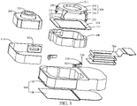
FIG. 1 is a schematic exploded view of a camera module disclosed in the embodiments of this disclosure; -
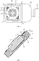
FIG. 2 is a schematic structural diagram of a camera module disclosed in the embodiments of this disclosure; -
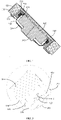
FIG. 3 is an A-A section view ofFIG. 2 ; -
FIG. 4 is a B-B section view ofFIG. 2 ; -
FIG. 5 is a partially enlarged diagram ofFIG. 4 ; -
FIG. 6 and FIG. 7 are schematic structural diagrams of a camera module under different viewing angles disclosed in the embodiments of this disclosure; and -
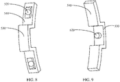
FIG. 8 and FIG. 9 are schematic structural diagrams of a second bracket under different viewing angles disclosed in the embodiments of this disclosure. - Reference signs are described as follows:
- 100. module housing; 110. inner housing chamber; 120. housing frame; 130. first cover plate; 131. second bypass hole; 140. second cover plate;
- 200. first bracket; 210. bracket body; 211. first bypass hole; 220. first connecting arm; 221. first hinge hole; 230. second connecting arm; 231. second hinge hole;
- 300. camera; 310. lens;
- 400. second bracket; 410. first depression; 420. second depression;
- 510. rolling-element bracket; 520. rolling element; 530. limiting protrusion;
- 610. first hinge shaft; 620. second hinge shaft;
- 700. flexible printed circuit board;
- 810. third bracket; 820. electromagnet.
- To make the objectives, technical solutions, and advantages of this disclosure clearer, the following clearly and completely describes the technical solutions of this disclosure with reference to specific embodiments of this disclosure and corresponding drawings. Apparently, the described embodiments are merely some rather than all the embodiments of this disclosure. All other embodiments that a person of ordinary skill in the art obtains without creative efforts based on the embodiments of this disclosure shall fall within the protection scope of this disclosure.
- The technical solutions disclosed in the embodiments of this disclosure are described in detail below with reference to the accompanying drawings.
- Referring to
FIG. 1 to FIG. 9 , an embodiment of this disclosure discloses a camera module, and the disclosed camera module may be applied to an electronic device. The disclosed camera module includes amodule housing 100, afirst bracket 200, acamera 300, asecond bracket 400, and a rolling-element bracket 510. - The
module housing 100 is a basic component of the camera module, and themodule housing 100 can provide a foundation for installing other components of the camera module. In this embodiment of this disclosure, themodule housing 100 has aninner housing chamber 110. Theinner housing chamber 110 has an opening, and the opening serves as a bypass. - The
first bracket 200 is at least partly disposed in theinner housing chamber 110, and thecamera 300 is at least partly disposed in theinner housing chamber 110. Thecamera 300 can take shots through the opening of theinner housing chamber 110. - In this embodiment of this disclosure, the
first bracket 200 is hinged to themodule housing 100 by afirst hinge shaft 610. Thefirst bracket 200 can rotate around thefirst hinge shaft 610. Thecamera 300 is fixedly connected to thesecond bracket 400, and the rolling-element bracket 510 is disposed with a rollingelement 520. The rollingelement 520 may be a ball or a roller. Thesecond bracket 400 is connected to the rollingelement 520 in a rolling mode, to allow relative rolling between the rolling-element bracket 510 and thesecond bracket 400. Specifically, thecamera 300 can rotate with thesecond bracket 400 around its lens axis by rolling. - The rolling-
element bracket 510 is hinged to thefirst bracket 200 by asecond hinge shaft 620, and thecamera 300 and thesecond bracket 400 can rotate with the rolling-element bracket 510 around thesecond hinge shaft 620. - In this embodiment of this disclosure, an axis of the
first hinge shaft 610 and an axis of thesecond hinge shaft 620 intersect or lie on different planes. The lens axis and the axis of thefirst hinge shaft 610 intersect or lie on different planes, and the lens axis and the axis of thesecond hinge shaft 620 intersect or lie on different planes. In other words, the rotating direction of thecamera 300 and thesecond bracket 400 relative to thefirst bracket 200, the rotating direction of thefirst bracket 200 relative to themodule housing 100, and the rotating direction of thecamera 300 with thesecond bracket 400 relative to the rolling-element bracket 510 are different from each other. - In a specific shooting process, the camera module may tilt due to shaking, eventually affecting the photograph quality. In the camera module disclosed in this embodiment of this disclosure, the
camera 300, thesecond bracket 400, and thefirst bracket 200 as a whole rotate around thefirst hinge shaft 610 relative to themodule housing 100, and thecamera 300 and thesecond bracket 400 as a whole rotate around thesecond hinge shaft 620 relative to thefirst bracket 200. Because the axis of thefirst hinge shaft 610 and the axis of thesecond hinge shaft 620 intersect or lie on different planes, rotations of thecamera 300 in the above two directions can compensate for the angular components of the tilt in these two directions caused by shaking of the camera module, thereby implementing effective anti-shake for the camera module. When thecamera 300 rotates around the axis of thefirst hinge shaft 610 or the axis of thesecond hinge shaft 620, thecamera 300 is also able to rotate with thesecond bracket 400, thereby enabling thecamera 300 to achieve a larger field of view for shooting. - In an optional solution, the axis of the
first hinge shaft 610 may be perpendicular to the axis of thesecond hinge shaft 620. In this case, an inclination angle generated by shaking of the entire camera module during shooting is easily resolved into two angular components around the axis of thefirst hinge shaft 610 and around the axis of thesecond hinge shaft 620 respectively, thereby facilitating angle compensation for thecamera 300 during rotation. - The
first bracket 200 may have various structures. In an optional solution, thefirst bracket 200 may include abracket body 210 and a first connectingarm 220, and a first end of the first connectingarm 220 is fixedly connected to thebracket body 210. A second end of the first connectingarm 220 is a free end. Thefirst hinge shaft 610 may be fastened on themodule housing 100, the second end of the first connectingarm 220 may be disposed with afirst hinge hole 221, and thefirst hinge shaft 610 is hinged to thefirst hinge hole 221. The first connectingarm 220 is hinged to themodule housing 100 by thefirst hinge shaft 610, helping reduce a space occupied by a hinge structure. In addition, the second end of the first connectingarm 220 is a free end, that is, the first connectingarm 220 is a cantilever structure. The second end of the first connectingarm 220 can extend into theinner housing chamber 110 to implement a hinged connection, helping miniaturize the entire camera module. - In an optional solution, the
first bracket 200 may further include a second connectingarm 230, where a first end of the second connectingarm 230 is fixedly connected to thebracket body 210, and a second end of the second connectingarm 230 is a free end. The second end of the second connectingarm 230 is disposed with asecond hinge hole 231, and thesecond hinge hole 231 is hinged to thesecond hinge shaft 620. Similarly, the second end of the second connectingarm 230 can extend into theinner housing chamber 110 to implement a hinged connection, helping miniaturize the entire module bracket. In addition, the second connectingarm 230 is a cantilever structure, and thesecond hinge hole 231 is disposed at the free end of the second connectingarm 230, so it is easier to implement a hinge assembly by deformation of the second connectingarm 230. - In an optional solution, to improve stability of the hinge, two such first connecting
arm 220 and two such secondconnecting arm 230 may be provided. The two first connectingarms 220 may be arranged diagonally on both sides of thecamera 300 respectively, that is, the two first connectingarms 220 may be symmetrically arranged on two sides of thecamera 300 relative to thecamera 300; and the two second connectingarms 230 may be arranged diagonally on two sides of thecamera 300 respectively, that is, the two second connectingarms 230 may be symmetrically arranged on two sides of thecamera 300 relative to thecamera 300. The two first connectingarms 220 and the two second connectingarms 230 are evenly and alternately arranged on the peripheral side of thebracket body 210. In this case, each first connectingarm 220 can be hinged to onefirst hinge shaft 610, and each second connectingarm 230 can be hinged to onesecond hinge shaft 620, which can undoubtedly improve the balance of rotation support. - In this embodiment of this disclosure, the
bracket body 210 is the main body part of thefirst bracket 200, and thebracket body 210 can ensure that the first connectingarm 220 and the second connectingarm 230 have a higher strength. Thebracket body 210 may have various structures. In an optional solution, thebracket body 210 may be provided with afirst bypass hole 211. Alens 310 of thecamera 300 may be disposed opposite thefirst bypass hole 211, and thelens 310 of thecamera 300 may take pictures through thefirst bypass hole 211. - Specifically, the
lens 310 of thecamera 300 may be completely located in theinner housing chamber 110, or may be located in thefirst bypass hole 211, or certainly, may extend out of theinner housing chamber 110 through thefirst bypass hole 211. In an optional solution, to prevent opening of thefirst bypass hole 211 from being excessively large, thelens 310 of thecamera 300 is located in thefirst bypass hole 211 or extends out of themodule housing 100 through thefirst bypass hole 211. In this case, it can be avoided that the opening of thefirst bypass hole 211 is too large under the same shooting field of view, or the above solution can undoubtedly achieve a larger shooting field of view of thelens 310 under a given opening size of thefirst bypass hole 211. Certainly, thelens 310 of thecamera 300 needs thefirst bypass hole 211 to form a gap around thelens 310, and the gap allows thecamera 300 to rotate in the rotating process of thecamera 300. - In an optional solution, to facilitate manufacturing and assembly, the
first bracket 200 may be an integral structure. Specifically, thefirst bracket 200 may be an integral metal structure. - Specifically, in a specific anti-shake process, the
camera 300 needs to rotate around the axis of thefirst hinge shaft 610 and/or the axis of thesecond hinge shaft 620. Thecamera 300 can be driven to rotate in various ways. - In an optional solution, the electronic device disclosed in this embodiment of this disclosure may further include a drive mechanism, and the drive mechanism may include a permanent magnet and an electromagnet. Specifically, the electronic device may be configured with a drive mechanism that matches each movement direction. Various types of drive components may be used, for example, implementing direct driving by a drive motor, or implementing driving by a drive motor in cooperation with a transmission mechanism. In an optional solution, each drive component may include a permanent magnet and an
electromagnet 820, and drive a movement by a magnetic force between the electromagnet and the permanent magnet after the electromagnet is electrified. - To facilitate assembly, the
electromagnet 820 may be installed on athird bracket 810, and thethird bracket 810 is disposed on themodule housing 100. In this case, the permanent magnet is installed on a component capable of relative rotation. When theelectromagnet 820 is electrified, the magnetic force generated by theelectromagnet 820 and the permanent magnet can drive a corresponding component to rotate. - In this embodiment of this disclosure, the
module housing 100 may have various structures. Still referring toFIG. 1 , in a specific implementation, themodule housing 100 may include ahousing frame 120, afirst cover plate 130, and asecond cover plate 140. Thefirst cover plate 130 is disposed on an opening at one end of thehousing frame 120, thesecond cover plate 140 is disposed on an opening at the other end of thehousing frame 120. Thefirst cover plate 130, thesecond cover plate 140 and thehousing frame 120 form theinner housing chamber 110. Thefirst cover plate 130 is provided with asecond bypass hole 131, and thesecond bypass hole 131 communicates with theinner housing chamber 110. Themodule housing 100 with the foregoing structure is assembly friendly, facilitating the installation of thecamera 300. On the premise that thebracket body 210 is provided with thefirst bypass hole 211, thefirst bypass hole 211 is located in the space encompassed by the hole wall of thesecond bypass hole 131. - Referring to
FIG. 6 to FIG. 9 , in an optional solution, thesecond bracket 400 may be provided with afirst depression 410, the rolling-element bracket 510 is disposed in thefirst depression 410, and the rollingelement 520 is disposed between the rolling-element bracket 510 and thefirst depression 410. A first bypass gap is present between the rolling-element bracket 510 and a side wall of thefirst depression 410, and the rolling-element bracket 510 fits the side wall of thefirst depression 410 in a position limited manner in the rolling direction of thesecond bracket 400, so that thesecond bracket 400 can rotate relative to the rolling-element bracket 510 only within a given angle range, so as to implement a small angle adjustment of the shooting field of view. - To improve the ease of assembly, the
second bracket 400 may be provided with asecond depression 420, thesecond depression 420 communicates with thefirst depression 410, the rolling-element bracket 510 is provided with a limitingprotrusion 530, and the limitingprotrusion 530 extends into thesecond depression 420 through thefirst depression 410, and forms a second bypass gap with a side wall of thesecond depression 420. The limitingprotrusion 530 fits the side wall of thesecond depression 420 in a position limited manner in the rolling direction of thesecond bracket 400. The first bypass gap has the same function as the second bypass gap, and both can implement the relative rolling of thesecond bracket 400 relative to the rolling-element bracket 510. - In an optional solution, to make the rolling more stable, at least two such rolling-
element brackets 510 are provided. The rolling-element brackets 510 may be spaced apart in the rotating direction of thesecond bracket 400, and a rollingelement 520 is disposed between each of the rolling-element brackets 510 and thesecond bracket 400. - To facilitate assembly, the
second hinge shaft 620 and the rolling-element bracket 510 may be an integral structure, as shown inFIG. 8 and FIG. 9 , so as to implement an integral installation with fewer installation steps. - Based on the camera module disclosed in this embodiment of this disclosure, an embodiment of this disclosure discloses an electronic device, and the disclosed electronic device includes the camera module described above. The
camera 300 can be electrically connected to the main board of the electronic device through a flexible printedcircuit board 700 that runs through themodule housing 100, thereby implementing power supply to thecamera 300. The flexible printedcircuit board 700 has a good ability to deform, and therefore can better adapt to the rotation of thecamera 300. - The electronic device in this embodiment of this disclosure may be a smart phone, a tablet computer, an e-book reader, a wearable device, or the like. The embodiments of this disclosure do not limit the specific type of the electronic device.
- The above embodiments of this disclosure focus on the differences between the embodiments. Provided that different features of improvement in the embodiments are not contradictory, they can be combined to form a more preferred embodiment. Further descriptions are omitted herein for the purpose of brevity.
- The foregoing descriptions are only embodiments of this disclosure, but this disclosure is not limited to such embodiments. For a person skilled in the art, this disclosure may have various changes and variations. Any modification, equivalent replacement, and improvement made without departing from the principle of this disclosure shall fall within the protection scope of the claims of this disclosure.
Claims (12)
- A camera module, comprising a module housing (100), a first bracket (200), a camera (300), a second bracket (400) and a rolling-element bracket (510), whereinthe module housing (100) has an inner housing chamber (110);the first bracket (200) is at least partly disposed in the inner housing chamber (110), the camera (300) is at least partly disposed in the inner housing chamber (110), the first bracket (200) is hinged to the module housing (100) by a first hinge shaft (610), and the first bracket (200) is able to rotate around the first hinge shaft (610);the camera (300) is fixedly connected to the second bracket (400), the rolling-element bracket (510) is disposed with a rolling element (520), the second bracket (400) is connected to the rolling element (520) in a rolling mode, the camera (300) is able to rotate with the second bracket (400) around its lens axis, the rolling-element bracket (510) is hinged to the first bracket (200) by a second hinge shaft (620), and the camera (300) and the second bracket (400) are able to rotate with the rolling-element bracket (510) around the second hinge shaft (620); andthe axis of the first hinge shaft (610) and the axis of the second hinge shaft (620) intersect or lie on different planes, the lens axis and the axis of the first hinge shaft (610) intersect or lie on different planes, and the lens axis and the axis of the second hinge shaft (620) intersect or lie on different planes.
- The camera module according to claim 1, wherein the first bracket (200) comprises a bracket body (210), a first connecting arm (220) and a second connecting arm (230), wherein one end of the first connecting arm (220) is fixedly connected to the bracket body (210), the other end of the first connecting arm (220) extends into the inner housing chamber (110) and is hinged to the module housing (100) by the first hinge shaft (610), one end of the second connecting arm (230) is fixedly connected to the bracket body (210), and the other end of the second connecting arm (230) extends into the inner housing chamber (110) and is hinged to the rolling-element bracket (510) by the second hinge shaft (620).
- The camera module according to claim 2, wherein two such first connecting arms (220) and two such second connecting arms (230) are provided, wherein the two first connecting arms (220) are arranged diagonally on two sides of the camera (300) respectively, and the two second connecting arms (230) are arranged diagonally on the other two sides of the camera (300) respectively.
- The camera module according to claim 2, wherein the bracket body (210) is provided with a first bypass hole (211), and a lens (310) of the camera (300) is disposed opposite to the first bypass hole (211).
- The camera module according to claim 2, wherein the first bracket (200) is an integral structure.
- The camera module according to claim 1, wherein the axis of the first hinge shaft (610) is perpendicular to the axis of the second hinge shaft (620).
- The camera module according to claim 1, wherein the module housing (100) comprises a housing frame (120), a first cover plate (130) and a second cover plate (140), the first cover plate (130) is disposed on an opening at one end of the housing frame (120), the second cover plate (140) is disposed on an opening at the other end of the housing frame (120), the first cover plate (130), the second cover plate (140) and the housing frame (120) form the inner housing chamber (110), the first cover plate (130) is provided with a second bypass hole (131), and the second bypass hole (131) communicates with the inner housing chamber (110).
- The camera module according to claim 1, wherein the second bracket (400) is provided with a first depression (410), and the rolling-element bracket (510) is disposed in the first depression (410), the rolling element (520) is disposed between the rolling-element bracket (510) and the first depression (410), a first bypass gap is present between the rolling-element bracket (510) and a side wall of the first depression (410), and the rolling-element bracket (510) fits the side wall of the first depression (410) in a position limited manner along the rolling direction of the second bracket (400).
- The camera module according to claim 8, wherein the second bracket (400) is provided with a second depression (420), the second depression (420) communicates with the first depression (410), the rolling-element bracket (510) is provided with a limiting protrusion (530), and the limiting protrusion (530) extends into the second depression (420) through the first depression (410), and forms a second bypass gap together with a side wall of the second depression (420), and the limiting protrusion (530) fits the side wall of the second depression (420) in a position limited manner along the rolling direction of the second bracket (400).
- The camera module according to claim 1, wherein at least two such rolling-element brackets (510) are provided, and the rolling-element brackets (510) are spaced apart in the rotating direction of the second bracket (400), the rolling element (520) is disposed between each of the rolling-element brackets (510) and the second bracket (400).
- The camera module according to claim 1, wherein the second hinge shaft (620) and the rolling-element bracket (510) are an integral structure.
- An electronic device, comprising the camera module according to any one of claims 1 to 11.
Applications Claiming Priority (2)
| Application Number | Priority Date | Filing Date | Title |
|---|---|---|---|
| CN201910942344.7A CN110572556B (en) | 2019-09-30 | 2019-09-30 | Camera module and electronic equipment |
| PCT/CN2020/117238 WO2021063231A1 (en) | 2019-09-30 | 2020-09-23 | Photographing module and electronic device |
Publications (3)
| Publication Number | Publication Date |
|---|---|
| EP4044573A1 true EP4044573A1 (en) | 2022-08-17 |
| EP4044573A4 EP4044573A4 (en) | 2022-11-23 |
| EP4044573B1 EP4044573B1 (en) | 2025-01-22 |
Family
ID=68783675
Family Applications (1)
| Application Number | Title | Priority Date | Filing Date |
|---|---|---|---|
| EP20873106.7A Active EP4044573B1 (en) | 2019-09-30 | 2020-09-23 | Photographing module and electronic device |
Country Status (10)
| Country | Link |
|---|---|
| US (1) | US12114055B2 (en) |
| EP (1) | EP4044573B1 (en) |
| JP (1) | JP7332798B2 (en) |
| KR (1) | KR102685319B1 (en) |
| CN (1) | CN110572556B (en) |
| AU (1) | AU2020359855B2 (en) |
| BR (1) | BR112022006088A2 (en) |
| CA (1) | CA3156125C (en) |
| ES (1) | ES3013622T3 (en) |
| WO (1) | WO2021063231A1 (en) |
Families Citing this family (19)
| Publication number | Priority date | Publication date | Assignee | Title |
|---|---|---|---|---|
| CN110677567B (en) | 2019-09-30 | 2020-11-13 | 维沃移动通信有限公司 | Camera module and electronic equipment |
| CN110572556B (en) * | 2019-09-30 | 2021-02-02 | 维沃移动通信有限公司 | Camera module and electronic equipment |
| CN113114873A (en) * | 2020-01-10 | 2021-07-13 | 华为技术有限公司 | Camera module and electronic equipment |
| KR102843872B1 (en) * | 2020-01-10 | 2025-08-08 | 삼성전자주식회사 | Camera module and electronic device including the same |
| KR102863881B1 (en) | 2020-01-10 | 2025-09-25 | 삼성전자주식회사 | Camera module and Electronic device including the same |
| CN111586269B (en) * | 2020-05-07 | 2022-02-18 | Oppo广东移动通信有限公司 | Imaging device and electronic apparatus |
| CN111474804B (en) * | 2020-05-07 | 2022-05-20 | Oppo广东移动通信有限公司 | Imaging device and electronic apparatus |
| CN111586268B (en) * | 2020-05-07 | 2021-10-15 | Oppo广东移动通信有限公司 | Imaging devices and electronic equipment |
| CN111586270B (en) * | 2020-05-07 | 2022-01-18 | Oppo广东移动通信有限公司 | Imaging device and electronic apparatus |
| CN111917965B (en) * | 2020-08-26 | 2025-01-28 | 河南皓泽电子股份有限公司昆山分公司 | Camera module and electronic equipment |
| CN112099287B (en) * | 2020-11-11 | 2021-02-09 | 常州市瑞泰光电有限公司 | Camera lens |
| CN112492173B (en) | 2020-12-07 | 2022-04-22 | 维沃移动通信有限公司 | Electronic device, image pickup apparatus, and anti-shake method and anti-shake apparatus for the same |
| CN112203011B (en) * | 2020-12-08 | 2021-02-19 | 常州市瑞泰光电有限公司 | Imaging device and electronic apparatus |
| CN112492218B (en) * | 2020-12-17 | 2022-04-08 | 维沃移动通信有限公司 | Camera module and electronic equipment |
| CN112736518B (en) * | 2020-12-22 | 2022-11-11 | 维沃移动通信有限公司 | Electronic device |
| CN112822354B (en) * | 2020-12-28 | 2023-01-31 | 维沃移动通信有限公司 | Camera module and electronic equipment |
| CN112822363B (en) * | 2020-12-31 | 2022-10-14 | 维沃移动通信有限公司 | Camera module and electronic equipment |
| CN112995469B (en) * | 2021-02-07 | 2022-10-11 | 维沃移动通信有限公司 | Imaging device and electronic apparatus |
| CN113286062B (en) * | 2021-04-19 | 2023-07-07 | 维沃移动通信有限公司 | Camera structure and electronics |
Family Cites Families (27)
| Publication number | Priority date | Publication date | Assignee | Title |
|---|---|---|---|---|
| JP2002354082A (en) * | 2001-05-23 | 2002-12-06 | Sharp Corp | Mobile phone with camera |
| CN2807646Y (en) * | 2005-04-27 | 2006-08-16 | 高浩贤 | Multiple view angle video camera |
| TWM322407U (en) * | 2007-05-02 | 2007-11-21 | Lite On Technology Corp | Micro-optical image stabilizer |
| JP4626780B2 (en) * | 2008-09-25 | 2011-02-09 | ミツミ電機株式会社 | Camera shake correction device |
| KR101589099B1 (en) * | 2009-11-06 | 2016-01-28 | 한화테크윈 주식회사 | Shake correction module and camera module having the shake correction module |
| KR101182775B1 (en) * | 2010-05-27 | 2012-09-14 | 삼성전기주식회사 | Camera module |
| US8649672B2 (en) * | 2010-06-09 | 2014-02-11 | Panasonic Corporation | Camera drive device |
| US9113051B1 (en) * | 2013-07-26 | 2015-08-18 | SkyBell Technologies, Inc. | Power outlet cameras |
| CN203745777U (en) * | 2014-01-10 | 2014-07-30 | 瑞声声学科技(深圳)有限公司 | Array type lens device |
| KR101771778B1 (en) * | 2014-04-11 | 2017-08-25 | 삼성전기주식회사 | Camera module |
| US9955077B2 (en) * | 2014-06-20 | 2018-04-24 | Samsung Electro-Mechanics Co., Ltd. | Camera module |
| KR102507054B1 (en) * | 2016-05-18 | 2023-03-07 | 삼성전자주식회사 | Camera and electronic device including the same |
| CN106534654B (en) * | 2016-12-30 | 2019-10-18 | 维沃移动通信有限公司 | Camera device, shooting method and device |
| CN106713557A (en) * | 2017-03-31 | 2017-05-24 | 努比亚技术有限公司 | Mobile terminal and control method thereof |
| KR102778488B1 (en) | 2017-05-03 | 2025-03-06 | 인터디지탈 패튼 홀딩스, 인크 | Beam-based PDCCH transmission in NR |
| JP6927776B2 (en) | 2017-07-13 | 2021-09-01 | 日本電産サンキョー株式会社 | Optical unit with runout correction function |
| CN207318817U (en) * | 2017-10-03 | 2018-05-04 | 惠州大亚湾三美达光学技术有限公司 | A kind of lens driver |
| US20190260943A1 (en) * | 2018-02-22 | 2019-08-22 | Perspective Components, Inc. | Methods for dynamic camera position adjustment |
| US11953703B2 (en) | 2018-02-23 | 2024-04-09 | Lg Innotek Co., Ltd. | Lens module and camera module including the same |
| CN108696687A (en) * | 2018-07-11 | 2018-10-23 | Oppo广东移动通信有限公司 | Camera assembly of electronic device and electronic device with same |
| CN208707750U (en) * | 2018-08-02 | 2019-04-05 | Oppo(重庆)智能科技有限公司 | A kind of camera and the electronic device with the camera |
| JP7303699B2 (en) | 2019-08-09 | 2023-07-05 | ニデックインスツルメンツ株式会社 | OPTICAL UNIT WITH STABILIZATION FUNCTION AND MANUFACTURING METHOD THEREOF |
| JP7269826B2 (en) | 2019-08-09 | 2023-05-09 | ニデックインスツルメンツ株式会社 | OPTICAL UNIT WITH STABILIZATION FUNCTION AND MANUFACTURING METHOD THEREOF |
| JP7376279B2 (en) | 2019-08-19 | 2023-11-08 | ニデックインスツルメンツ株式会社 | Optical unit with shake correction function |
| CN110572556B (en) * | 2019-09-30 | 2021-02-02 | 维沃移动通信有限公司 | Camera module and electronic equipment |
| KR102843872B1 (en) * | 2020-01-10 | 2025-08-08 | 삼성전자주식회사 | Camera module and electronic device including the same |
| US12250578B2 (en) | 2020-04-03 | 2025-03-11 | Qualcomm Incorporated | Physical downlink control channel (PDCCH) aggregation across monitoring occasions |
-
2019
- 2019-09-30 CN CN201910942344.7A patent/CN110572556B/en active Active
-
2020
- 2020-09-23 WO PCT/CN2020/117238 patent/WO2021063231A1/en not_active Ceased
- 2020-09-23 AU AU2020359855A patent/AU2020359855B2/en active Active
- 2020-09-23 ES ES20873106T patent/ES3013622T3/en active Active
- 2020-09-23 JP JP2022519750A patent/JP7332798B2/en active Active
- 2020-09-23 KR KR1020227011410A patent/KR102685319B1/en active Active
- 2020-09-23 EP EP20873106.7A patent/EP4044573B1/en active Active
- 2020-09-23 CA CA3156125A patent/CA3156125C/en active Active
- 2020-09-23 BR BR112022006088A patent/BR112022006088A2/en unknown
-
2022
- 2022-03-29 US US17/707,402 patent/US12114055B2/en active Active
Also Published As
| Publication number | Publication date |
|---|---|
| EP4044573A4 (en) | 2022-11-23 |
| AU2020359855A1 (en) | 2022-05-19 |
| KR102685319B1 (en) | 2024-07-16 |
| BR112022006088A2 (en) | 2022-06-21 |
| CN110572556B (en) | 2021-02-02 |
| US12114055B2 (en) | 2024-10-08 |
| JP7332798B2 (en) | 2023-08-23 |
| AU2020359855B2 (en) | 2023-06-15 |
| CA3156125A1 (en) | 2021-04-08 |
| ES3013622T3 (en) | 2025-04-14 |
| CN110572556A (en) | 2019-12-13 |
| CA3156125C (en) | 2024-10-22 |
| WO2021063231A1 (en) | 2021-04-08 |
| EP4044573B1 (en) | 2025-01-22 |
| US20220224807A1 (en) | 2022-07-14 |
| KR20220058943A (en) | 2022-05-10 |
| JP2022549943A (en) | 2022-11-29 |
Similar Documents
| Publication | Publication Date | Title |
|---|---|---|
| US12114055B2 (en) | Camera module and electronic device supporting anti-shake and larger field of view for shooting | |
| US12028596B2 (en) | Camera module and electronic device | |
| KR102701120B1 (en) | Camera modules and electronics | |
| WO2021197148A1 (en) | Camera module and electronic device | |
| WO2021208898A1 (en) | Camera module and electronic device | |
| CN112822354B (en) | Camera module and electronic equipment | |
| EP4274213A1 (en) | Camera module and electronic device | |
| CN113411470B (en) | Camera module and electronic equipment | |
| EP4270919A1 (en) | Camera module and electronic device | |
| CN209497532U (en) | Drive mechanism assembly and pan-tilt shooting device | |
| CA3156077C (en) | Camera module and electronic device | |
| EP4422191A1 (en) | Camera assembly and electronic device | |
| CN114697510B (en) | Optical image stabilization camera module and optical image stabilization method | |
| WO2022120930A1 (en) | Camera apparatus and electronic device | |
| US12464212B2 (en) | Electronic device for reducing height dimension of camera module decorative part | |
| US12081872B2 (en) | Anti-shake camera and terminal | |
| CN115278028A (en) | Camera module and electronic equipment |
Legal Events
| Date | Code | Title | Description |
|---|---|---|---|
| STAA | Information on the status of an ep patent application or granted ep patent |
Free format text: STATUS: THE INTERNATIONAL PUBLICATION HAS BEEN MADE |
|
| PUAI | Public reference made under article 153(3) epc to a published international application that has entered the european phase |
Free format text: ORIGINAL CODE: 0009012 |
|
| STAA | Information on the status of an ep patent application or granted ep patent |
Free format text: STATUS: REQUEST FOR EXAMINATION WAS MADE |
|
| 17P | Request for examination filed |
Effective date: 20220426 |
|
| AK | Designated contracting states |
Kind code of ref document: A1 Designated state(s): AL AT BE BG CH CY CZ DE DK EE ES FI FR GB GR HR HU IE IS IT LI LT LU LV MC MK MT NL NO PL PT RO RS SE SI SK SM TR |
|
| A4 | Supplementary search report drawn up and despatched |
Effective date: 20221020 |
|
| RIC1 | Information provided on ipc code assigned before grant |
Ipc: H04N 5/232 20060101ALI20221014BHEP Ipc: H04N 5/225 20060101AFI20221014BHEP |
|
| DAV | Request for validation of the european patent (deleted) | ||
| DAX | Request for extension of the european patent (deleted) | ||
| REG | Reference to a national code |
Ref legal event code: R079 Free format text: PREVIOUS MAIN CLASS: H04N0005225000 Ipc: H04N0023510000 Ref country code: DE Ref document number: 602020045320 Country of ref document: DE |
|
| GRAP | Despatch of communication of intention to grant a patent |
Free format text: ORIGINAL CODE: EPIDOSNIGR1 |
|
| STAA | Information on the status of an ep patent application or granted ep patent |
Free format text: STATUS: GRANT OF PATENT IS INTENDED |
|
| RIC1 | Information provided on ipc code assigned before grant |
Ipc: H04N 23/68 20230101ALI20240814BHEP Ipc: H04N 23/57 20230101ALI20240814BHEP Ipc: H04N 23/55 20230101ALI20240814BHEP Ipc: H04N 23/51 20230101AFI20240814BHEP |
|
| INTG | Intention to grant announced |
Effective date: 20240905 |
|
| GRAS | Grant fee paid |
Free format text: ORIGINAL CODE: EPIDOSNIGR3 |
|
| GRAA | (expected) grant |
Free format text: ORIGINAL CODE: 0009210 |
|
| STAA | Information on the status of an ep patent application or granted ep patent |
Free format text: STATUS: THE PATENT HAS BEEN GRANTED |
|
| AK | Designated contracting states |
Kind code of ref document: B1 Designated state(s): AL AT BE BG CH CY CZ DE DK EE ES FI FR GB GR HR HU IE IS IT LI LT LU LV MC MK MT NL NO PL PT RO RS SE SI SK SM TR |
|
| REG | Reference to a national code |
Ref country code: GB Ref legal event code: FG4D |
|
| REG | Reference to a national code |
Ref country code: CH Ref legal event code: EP |
|
| REG | Reference to a national code |
Ref country code: IE Ref legal event code: FG4D |
|
| REG | Reference to a national code |
Ref country code: DE Ref legal event code: R096 Ref document number: 602020045320 Country of ref document: DE |
|
| REG | Reference to a national code |
Ref country code: NL Ref legal event code: FP |
|
| REG | Reference to a national code |
Ref country code: ES Ref legal event code: FG2A Ref document number: 3013622 Country of ref document: ES Kind code of ref document: T3 Effective date: 20250414 |
|
| PG25 | Lapsed in a contracting state [announced via postgrant information from national office to epo] |
Ref country code: RS Free format text: LAPSE BECAUSE OF FAILURE TO SUBMIT A TRANSLATION OF THE DESCRIPTION OR TO PAY THE FEE WITHIN THE PRESCRIBED TIME-LIMIT Effective date: 20250422 |
|
| PG25 | Lapsed in a contracting state [announced via postgrant information from national office to epo] |
Ref country code: FI Free format text: LAPSE BECAUSE OF FAILURE TO SUBMIT A TRANSLATION OF THE DESCRIPTION OR TO PAY THE FEE WITHIN THE PRESCRIBED TIME-LIMIT Effective date: 20250122 |
|
| PG25 | Lapsed in a contracting state [announced via postgrant information from national office to epo] |
Ref country code: PL Free format text: LAPSE BECAUSE OF FAILURE TO SUBMIT A TRANSLATION OF THE DESCRIPTION OR TO PAY THE FEE WITHIN THE PRESCRIBED TIME-LIMIT Effective date: 20250122 |
|
| REG | Reference to a national code |
Ref country code: LT Ref legal event code: MG9D |
|
| PG25 | Lapsed in a contracting state [announced via postgrant information from national office to epo] |
Ref country code: IS Free format text: LAPSE BECAUSE OF FAILURE TO SUBMIT A TRANSLATION OF THE DESCRIPTION OR TO PAY THE FEE WITHIN THE PRESCRIBED TIME-LIMIT Effective date: 20250522 Ref country code: NO Free format text: LAPSE BECAUSE OF FAILURE TO SUBMIT A TRANSLATION OF THE DESCRIPTION OR TO PAY THE FEE WITHIN THE PRESCRIBED TIME-LIMIT Effective date: 20250422 |
|
| REG | Reference to a national code |
Ref country code: AT Ref legal event code: MK05 Ref document number: 1762358 Country of ref document: AT Kind code of ref document: T Effective date: 20250122 |
|
| PG25 | Lapsed in a contracting state [announced via postgrant information from national office to epo] |
Ref country code: HR Free format text: LAPSE BECAUSE OF FAILURE TO SUBMIT A TRANSLATION OF THE DESCRIPTION OR TO PAY THE FEE WITHIN THE PRESCRIBED TIME-LIMIT Effective date: 20250122 |
|
| PG25 | Lapsed in a contracting state [announced via postgrant information from national office to epo] |
Ref country code: PT Free format text: LAPSE BECAUSE OF FAILURE TO SUBMIT A TRANSLATION OF THE DESCRIPTION OR TO PAY THE FEE WITHIN THE PRESCRIBED TIME-LIMIT Effective date: 20250522 Ref country code: LV Free format text: LAPSE BECAUSE OF FAILURE TO SUBMIT A TRANSLATION OF THE DESCRIPTION OR TO PAY THE FEE WITHIN THE PRESCRIBED TIME-LIMIT Effective date: 20250122 |
|
| PG25 | Lapsed in a contracting state [announced via postgrant information from national office to epo] |
Ref country code: GR Free format text: LAPSE BECAUSE OF FAILURE TO SUBMIT A TRANSLATION OF THE DESCRIPTION OR TO PAY THE FEE WITHIN THE PRESCRIBED TIME-LIMIT Effective date: 20250423 Ref country code: BG Free format text: LAPSE BECAUSE OF FAILURE TO SUBMIT A TRANSLATION OF THE DESCRIPTION OR TO PAY THE FEE WITHIN THE PRESCRIBED TIME-LIMIT Effective date: 20250122 |
|
| PG25 | Lapsed in a contracting state [announced via postgrant information from national office to epo] |
Ref country code: AT Free format text: LAPSE BECAUSE OF FAILURE TO SUBMIT A TRANSLATION OF THE DESCRIPTION OR TO PAY THE FEE WITHIN THE PRESCRIBED TIME-LIMIT Effective date: 20250122 |
|
| PG25 | Lapsed in a contracting state [announced via postgrant information from national office to epo] |
Ref country code: SE Free format text: LAPSE BECAUSE OF FAILURE TO SUBMIT A TRANSLATION OF THE DESCRIPTION OR TO PAY THE FEE WITHIN THE PRESCRIBED TIME-LIMIT Effective date: 20250122 |
|
| PGFP | Annual fee paid to national office [announced via postgrant information from national office to epo] |
Ref country code: NL Payment date: 20250814 Year of fee payment: 6 |
|
| PG25 | Lapsed in a contracting state [announced via postgrant information from national office to epo] |
Ref country code: SM Free format text: LAPSE BECAUSE OF FAILURE TO SUBMIT A TRANSLATION OF THE DESCRIPTION OR TO PAY THE FEE WITHIN THE PRESCRIBED TIME-LIMIT Effective date: 20250122 |
|
| PG25 | Lapsed in a contracting state [announced via postgrant information from national office to epo] |
Ref country code: DK Free format text: LAPSE BECAUSE OF FAILURE TO SUBMIT A TRANSLATION OF THE DESCRIPTION OR TO PAY THE FEE WITHIN THE PRESCRIBED TIME-LIMIT Effective date: 20250122 |
|
| PGFP | Annual fee paid to national office [announced via postgrant information from national office to epo] |
Ref country code: DE Payment date: 20250730 Year of fee payment: 6 |
|
| PGFP | Annual fee paid to national office [announced via postgrant information from national office to epo] |
Ref country code: IT Payment date: 20250825 Year of fee payment: 6 |
|
| PGFP | Annual fee paid to national office [announced via postgrant information from national office to epo] |
Ref country code: GB Payment date: 20250731 Year of fee payment: 6 |
|
| PGFP | Annual fee paid to national office [announced via postgrant information from national office to epo] |
Ref country code: FR Payment date: 20250808 Year of fee payment: 6 |
|
| PG25 | Lapsed in a contracting state [announced via postgrant information from national office to epo] |
Ref country code: CZ Free format text: LAPSE BECAUSE OF FAILURE TO SUBMIT A TRANSLATION OF THE DESCRIPTION OR TO PAY THE FEE WITHIN THE PRESCRIBED TIME-LIMIT Effective date: 20250122 Ref country code: EE Free format text: LAPSE BECAUSE OF FAILURE TO SUBMIT A TRANSLATION OF THE DESCRIPTION OR TO PAY THE FEE WITHIN THE PRESCRIBED TIME-LIMIT Effective date: 20250122 |
|
| REG | Reference to a national code |
Ref country code: DE Ref legal event code: R097 Ref document number: 602020045320 Country of ref document: DE |
|
| PG25 | Lapsed in a contracting state [announced via postgrant information from national office to epo] |
Ref country code: RO Free format text: LAPSE BECAUSE OF FAILURE TO SUBMIT A TRANSLATION OF THE DESCRIPTION OR TO PAY THE FEE WITHIN THE PRESCRIBED TIME-LIMIT Effective date: 20250122 |
|
| PG25 | Lapsed in a contracting state [announced via postgrant information from national office to epo] |
Ref country code: SK Free format text: LAPSE BECAUSE OF FAILURE TO SUBMIT A TRANSLATION OF THE DESCRIPTION OR TO PAY THE FEE WITHIN THE PRESCRIBED TIME-LIMIT Effective date: 20250122 |
|
| PLBE | No opposition filed within time limit |
Free format text: ORIGINAL CODE: 0009261 |
|
| STAA | Information on the status of an ep patent application or granted ep patent |
Free format text: STATUS: NO OPPOSITION FILED WITHIN TIME LIMIT |
|
| REG | Reference to a national code |
Ref country code: CH Ref legal event code: L10 Free format text: ST27 STATUS EVENT CODE: U-0-0-L10-L00 (AS PROVIDED BY THE NATIONAL OFFICE) Effective date: 20251203 |
|
| 26N | No opposition filed |
Effective date: 20251023 |
|
| PGFP | Annual fee paid to national office [announced via postgrant information from national office to epo] |
Ref country code: ES Payment date: 20251016 Year of fee payment: 6 |
|
| REG | Reference to a national code |
Ref country code: CH Ref legal event code: H13 Free format text: ST27 STATUS EVENT CODE: U-0-0-H10-H13 (AS PROVIDED BY THE NATIONAL OFFICE) Effective date: 20260504 |