EP4044572A1 - Image forming apparatus, method of forming gradation patch, and evaluation chart of the image forming apparatus - Google Patents
Image forming apparatus, method of forming gradation patch, and evaluation chart of the image forming apparatus Download PDFInfo
- Publication number
- EP4044572A1 EP4044572A1 EP21218313.1A EP21218313A EP4044572A1 EP 4044572 A1 EP4044572 A1 EP 4044572A1 EP 21218313 A EP21218313 A EP 21218313A EP 4044572 A1 EP4044572 A1 EP 4044572A1
- Authority
- EP
- European Patent Office
- Prior art keywords
- sheet
- gradation
- image
- image forming
- gradation patches
- Prior art date
- Legal status (The legal status is an assumption and is not a legal conclusion. Google has not performed a legal analysis and makes no representation as to the accuracy of the status listed.)
- Granted
Links
Images











Classifications
-
- H—ELECTRICITY
- H04—ELECTRIC COMMUNICATION TECHNIQUE
- H04N—PICTORIAL COMMUNICATION, e.g. TELEVISION
- H04N1/00—Scanning, transmission or reproduction of documents or the like, e.g. facsimile transmission; Details thereof
- H04N1/40—Picture signal circuits
- H04N1/407—Control or modification of tonal gradation or of extreme levels, e.g. background level
-
- G—PHYSICS
- G06—COMPUTING OR CALCULATING; COUNTING
- G06K—GRAPHICAL DATA READING; PRESENTATION OF DATA; RECORD CARRIERS; HANDLING RECORD CARRIERS
- G06K15/00—Arrangements for producing a permanent visual presentation of the output data, e.g. computer output printers
- G06K15/40—Details not directly involved in printing, e.g. machine management, management of the arrangement as a whole or of its constitutive parts
-
- H—ELECTRICITY
- H04—ELECTRIC COMMUNICATION TECHNIQUE
- H04N—PICTORIAL COMMUNICATION, e.g. TELEVISION
- H04N1/00—Scanning, transmission or reproduction of documents or the like, e.g. facsimile transmission; Details thereof
- H04N1/46—Colour picture communication systems
- H04N1/56—Processing of colour picture signals
- H04N1/60—Colour correction or control
- H04N1/6027—Correction or control of colour gradation or colour contrast
-
- H—ELECTRICITY
- H04—ELECTRIC COMMUNICATION TECHNIQUE
- H04N—PICTORIAL COMMUNICATION, e.g. TELEVISION
- H04N1/00—Scanning, transmission or reproduction of documents or the like, e.g. facsimile transmission; Details thereof
- H04N1/46—Colour picture communication systems
- H04N1/56—Processing of colour picture signals
- H04N1/60—Colour correction or control
- H04N1/603—Colour correction or control controlled by characteristics of the picture signal generator or the picture reproducer
- H04N1/6033—Colour correction or control controlled by characteristics of the picture signal generator or the picture reproducer using test pattern analysis
Definitions
- the evaluation chart includes a sheet, an image formed in an image area on the sheet by the image forming apparatus, and a plurality of gradation patches formed in an area outside the image area and having widths different from each other in the conveyance direction of the sheet.
- spatially relative terms such as “beneath,” “below,” “lower,” “above,” “upper” and the like may be used herein for ease of description to describe one element or feature's relationship to another element(s) or feature(s) as illustrated in the figures. It will be understood that the spatially relative terms are intended to encompass different orientations of the device in use or operation in addition to the orientation depicted in the figures. For example, if the device in the figures is turned over, elements describes as “below” or “beneath” other elements or features would then be oriented “above” the other elements or features. Thus, term such as “below” can encompass both an orientation of above and below. The device may be otherwise oriented (rotated 90 degrees or at other orientations) and the spatially relative descriptors herein interpreted accordingly.
- the developing units of the image forming units 215 supply respective toners onto the respective electrostatic latent images of the photoconductor units 214Y, 214M, 214C, and 214K, each corresponding to yellow (y), magenta (m), cyan (c), and black (k). By so doing, respective single toner images are formed.
- the sheet S is conveyed to the inspection device 240.
- the sheet S having the image on the second face is further conveyed, so that the image on the second face of the sheet S is fixed to the sheet S in the fixing device 230. Then, the sheet S is conveyed to the inspection device 240.
- the inspection device 240 includes two (upper and lower) inline sensors 241 across the conveyance passage of the sheet S.
- Each of the inline sensors 241 functions as an image reader that reads an image formed on the sheet S.
- the two inline sensors 241 read front and back faces of the sheet S at one time.
- the scanner controller 308 controls the scanner 202.
- the printer controller 307 executes image processing on input image data, and controls laser diodes (LDs) of the image forming units 215 to expose light toward the photoconductor units 214.
- the printer controller 307 performs color correction and generates gradation patches for the color correction, based on the analysis result obtained by the inspector controller 309.
- LDs laser diodes
- the panel controller 306 receives instructions from a user, so that processings such as copying, sending a facsimile, scanning, and storing images are executed.
- the controller 300 controls formation of gradation patches.
- the controller 300 acquires density information from image information of a printed image and determines the width of a gradation patch P in the conveyance direction of the sheet S based on the acquired density information.
- Each of the gradation patches P is either a gradation patch Pa or a gradation patch Pb.
- the gradation patch Pa has a wider (thicker) width in the conveyance direction of the sheet S.
- the gradation patch Pb has a narrower (thinner) width in the conveyance direction of the sheet S.
- the width in the conveyance direction is equal to the width in the sub-sheet conveyance direction and is also referred to as a "sub-scanning width.”
- the gradation patches P1 to P5 are classified to the gradation patches Pb having a thinner (narrower) sub-scanning width
- the gradation patches P6 to P8 are classified to the gradation patches Pa having a thicker (wider) sub-scanning width.
- the image forming apparatus achieves the real-time printing performance.
- the adjacent gradation patch patterns 400 of different colors are formed to change in colors of the gradation patches, for example, in the conveyance direction of the sheet S.
- the gradation patches in the odd-numbered gradation patch patterns 400 i.e., gradation patch patterns 400K and 400M
- the gradation patches in the even-numbered gradation patch patterns 400 i.e., gradation patch patterns 400C and 400Y
- the difference in density is low between the adjacent gradation patches of the adjacent gradation patch patterns 400.
- the adjacent gradation patches in adjacent two different colors of gradation patches of the gradation patch patterns 400 have a smaller density difference in color than non-gradation patches of a same color in the adjacent two different colors of gradation patches (i.e., gradation patch patterns 400K and 400M).
- the gradation patch patterns 400 (i.e., gradation patch patterns 400K, 400C, 400M, and 400Y) illustrated in FIG. 4A to be used for color correction are formed in the margin areas SB (side end margin areas) on both sides in a direction orthogonal to the conveyance direction of the sheet S, in other words, the main scanning direction.
- the gradation patch patterns 400 are formed outside the image area SA and in the margin area SB outside the cut lines of the sheet.
- the margin area SB on each side of the sheet S has the width of (sheet size - image area) / 2.
- the gradation patch patterns 400 When the printing of the gradation patch patterns 400 in the main scanning direction shifts (deviates) within the margin area SB, the gradation patch patterns 400 partly exceed out of the side of the sheet S.
- the gradation patch patterns 400 are spaced from the image area SA so as not to adjoin the image area SA.
- the width narrower (smaller) than the width of (sheet size - image area) / 2 is determined as the length of the gradation patch patterns 400 in the main scanning direction.
- the arrangement of the gradation patch patterns 400 on the margin area SC at the leading end of the sheet S and the margin area SD at the trailing end of the sheet S has the priority over the arrangement of the gradation patch patterns 400 on the margin areas SB.
- FIG. 7 is a diagram illustrating a density information acquiring process in the flowchart of FIG. 6 .
- the image data is divided by area unit of the pixels in the main scanning direction X and the sub-scanning direction Y to measure the average of pixel densities of colors of cyan (C), magenta (M), yellow (Y), and black (K) of each area.
- the measured average value is a gradation value.
- the image data in FIG. 7 is divided into regions of "main scanning N ⁇ sub-scanning M.”
- Measuring the gradation value by area unit is an operation of converting the density of the target pixels in a divided region and measuring the average of pixel densities is an operation of dividing the converted value by the number of pixels in the region.
- the gradation values from 0 to 255 are classified into eight (8) gradation range groups (No. 1 to No. 8). Then, the density values of colors of black (K), cyan (C), magenta (M), and yellow (Y) in the divided region are counted by eight (8) categories.
- the sub-scanning width of the gradation patch P of non-priority gradation is half of the reference patch width.
- the sub-scanning width of the gradation patch P of priority gradation i.e., the gradation patch Pa
- This process is executed at the start of the printing operation in response to an instruction of execution of printing by a user.
- the inspector controller 309 determines whether a patch image is formed in the sheet S (S31). This determination is performed by checking patch image presence information from the CPU 301.
- FIG. 11 is a diagram illustrating the gradation patches of the image forming apparatus according to the second embodiment of the present disclosure.
- FIG. 13 is a diagram illustrating gradation patches of an image forming apparatus according to the third embodiment of the present disclosure.
- the real-time printing performance of the image forming apparatus is enhanced.
- the gradation patch patterns 400 according to the fourth embodiment is achieved even when images are printed on both faces (first and second faces) of the sheet S. That is, as illustrated in FIG. 16 , when the first face of the first sheet SH1 is assumed to be a preceding sheet, the density information is acquired from the image information of a print image for the second face of the first sheet SH1 as a subsequent sheet.
- the density information is acquired from the print information for a subsequent sheet that is two or more sheets away from the preceding sheet, so as to form the gradation patches P of the gradation patch patterns 400.
- the density information is acquired from the image information of a print image for a fourth sheet SH4 as a subsequent sheet.
- the fourth sheet SH4 is three sheets after the preceding sheet.
- the sub-scanning width of each of the gradation patches P included in the gradation patch patterns 400 is determined from the acquired density information, and the gradation patches P having the sub-scanning widths different from each other are formed in the margin areas SB of the first sheet SH1 as a preceding sheet.
- the controller 300 executes regular image processing and color correction calculated from the reading result of the gradation patches P of the gradation patch patterns 400 by the inspection device 240 in steps S45 and S46 and does not form the gradation patches P when printing the print image (print data) for the (N)th page.
- the width of the whole gradation patch pattern 400K (Nos. 1 to 9) for the color of yellow is set to be greater than the width of the whole gradation patch pattern 400M (Nos. 1 to 9) for the color of magenta.
- the number of gradations of the gradation patch pattern 400K is greater than the number of gradations of the gradation patch pattern 400M (400C and 400Y) or no gradation patch patterns 400 (400C and 400Y in FIG. 19 ) is formed.
Landscapes
- Engineering & Computer Science (AREA)
- Multimedia (AREA)
- Signal Processing (AREA)
- General Engineering & Computer Science (AREA)
- Physics & Mathematics (AREA)
- General Physics & Mathematics (AREA)
- Theoretical Computer Science (AREA)
- Control Or Security For Electrophotography (AREA)
- Facsimile Image Signal Circuits (AREA)
- Accessory Devices And Overall Control Thereof (AREA)
- Health & Medical Sciences (AREA)
- Biomedical Technology (AREA)
- General Health & Medical Sciences (AREA)
Abstract
Description
- Embodiments of the present disclosure relate to an image forming apparatus, a method of forming gradation patches, and an evaluation chart of the image forming apparatus.
- Various known image forming apparatuses forms gradation patches for density correction on a sheet, causes an image reading device (e.g., inline sensor) to read the gradation patches, and performs correction based on the reading result.
- A known image forming apparatus includes a print image analyzing unit and a patch image position determining unit. The print image analyzing unit analyzes the position of a print image to be formed in an image formation area of a sheet, on the sheet. The patch image position determining unit determines the position of a patch image for image correction to be formed in an area outside the image forming area on the surface of the sheet, based on the analysis result of the print image analyzing unit. For example,
Japanese Unexamined Patent Publication No. 2018-005173 - In a case in which a reading target (density detection area) to be read by an image reading device (inline sensor) is disposed at a position close to the gradation patch that is not a reading target, the gradation patch cannot be read correctly. This phenomenon is known as "flare." In addition, as the difference in density of reading target increases, the level of an adverse effect due to flare becomes greater.
- If the gradation patch is simply increased (widened) to prevent the adverse effect due to flare, the margin area is limited. Due to the limitation of the margin area, the real-time printing performance of the image forming apparatus is compromised, for example, the gradation patches are to be formed over multiple sheets.
- In view of the above-described disadvantages, an object of the present disclosure is to provide an image reading device to enhance the cleanability in an image reading device.
- Embodiments of the present disclosure described herein provide a novel image forming apparatus including and image forming device and a control unit. The image forming device is configured to form an image on a sheet. The control unit is configured to acquire density information from image information of the image printed on the sheet, determine a width of each of a plurality of gradation patches to be formed in a conveyance direction of the sheet based on the acquired density information, and cause the image forming device to form the plurality of gradation patches having different widths from each other in the conveyance direction of the sheet, in a margin area of the sheet.
- Further, embodiments of the present disclosure described herein provide a method of forming a plurality of gradation patches. The method includes acquiring density information from image information of an image formed on a sheet, determining a width of each of the plurality of gradation patches to be formed in a conveyance direction of a sheet, based on the acquired density information, and forming the plurality of gradation patches having different widths from each other in the conveyance direction of the sheet, in a margin area of the sheet.
- Further, embodiments of the present disclosure described herein provide an evaluation chart for an image forming apparatus. The evaluation chart includes a sheet, an image formed in an image area on the sheet by the image forming apparatus, and a plurality of gradation patches formed in an area outside the image area and having widths different from each other in the conveyance direction of the sheet.
- According to the present disclosure, the real-time printing performance of the image forming apparatus is not impaired.
- Exemplary embodiments of this disclosure will be described in detail based on the following figures, wherein:
-
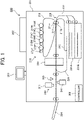
FIG. 1 is a side view of an image forming apparatus according to a first embodiment of the present disclosure; -
FIG. 2 is a block diagram illustrating the image forming apparatus ofFIG. 1 ; -
FIGS. 3A and 3B are diagrams, each illustrating an evaluation chart of the image forming apparatus according to the first embodiment of the present disclosure; -
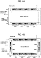
FIG. 4A is a plan view of an arrangement of gradation patch pattern (gradation patch image) formed on a sheet by the image forming apparatus ofFIG. 1 ; -
FIG. 4B is a plan view of another arrangement of gradation patch pattern (gradation patch image) formed on the sheet by the image forming apparatus ofFIG. 1 ; -
FIG. 5 is a flowchart of a printing process (image forming process) of a gradation patch image (gradation patch pattern) executed by the controller, according to the first embodiment of the present disclosure; -
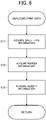
FIG. 6 is a flowchart of an analyzing process of print data (print image) ofFIG. 5 ; -
FIG. 7 is a diagram illustrating a density information acquiring process in the flowchart ofFIG. 6 ; -
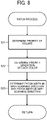
FIG. 8 is a flowchart of a patch process that determines a patch shape in the flowchart ofFIG. 5 ; -
FIG. 9 is a diagram illustrating a priority gradation determining process in the flowchart ofFIG. 8 ; -
FIG. 10 is a flowchart of the operations performed by an inspection device; -
FIG. 11 is a diagram illustrating a gradation patch of the image forming apparatus according to a second embodiment of the present disclosure; -
FIG. 12 is a diagram illustrating a priority gradation determining process according to the second embodiment of the present disclosure; -
FIG. 13 is a diagram illustrating a gradation patch of an image forming apparatus according to a third embodiment of the present disclosure; -
FIG. 14 is a diagram illustrating an operation performed by an image forming apparatus according to a fourth embodiment of the present disclosure; -
FIG. 15 is a diagram illustrating an image forming apparatus according to a fifth embodiment of the present disclosure; -
FIG. 16 is a diagram illustrating an operation performed by the image forming apparatus according to the fifth embodiment of the present disclosure; -
FIG. 17 is a diagram illustrating an operation performed by an image forming apparatus according to a sixth embodiment of the present disclosure; -
FIG. 18 is a flowchart of a printing process of gradation patch by the controller, according to the fifth embodiment of the present disclosure; and -
FIG. 19 is a diagram illustrating a gradation patch pattern of an image forming apparatus according to a seventh embodiment of the present disclosure. - The accompanying drawings are intended to depict embodiments of the present disclosure and should not be interpreted to limit the scope thereof. The accompanying drawings are not to be considered as drawn to scale unless explicitly noted.
- It will be understood that if an element or layer is referred to as being "on," "against," "connected to" or "coupled to" another element or layer, then it can be directly on, against, connected or coupled to the other element or layer, or intervening elements or layers may be present. In contrast, if an element is referred to as being "directly on," "directly connected to" or "directly coupled to" another element or layer, then there are no intervening elements or layers present. Like numbers referred to like elements throughout. As used herein, the term "and/or" includes any and all combinations of one or more of the associated listed items.
- Spatially relative terms, such as "beneath," "below," "lower," "above," "upper" and the like may be used herein for ease of description to describe one element or feature's relationship to another element(s) or feature(s) as illustrated in the figures. It will be understood that the spatially relative terms are intended to encompass different orientations of the device in use or operation in addition to the orientation depicted in the figures. For example, if the device in the figures is turned over, elements describes as "below" or "beneath" other elements or features would then be oriented "above" the other elements or features. Thus, term such as "below" can encompass both an orientation of above and below. The device may be otherwise oriented (rotated 90 degrees or at other orientations) and the spatially relative descriptors herein interpreted accordingly.
- The terminology used herein is for describing particular embodiments and examples and is not intended to be limiting of exemplary embodiments of this disclosure. As used herein, the singular forms "a," "an," and "the" are intended to include the plural forms as well, unless the context clearly indicates otherwise. It will be further understood that the terms "includes" and/or "including," when used in this specification, specify the presence of stated features, integers, steps, operations, elements, and/or components, but do not preclude the presence or addition of one or more other features, integers, steps, operations, elements, components, and/or groups thereof.
- Referring now to the drawings, embodiments of the present disclosure are described below. In the drawings for explaining the following embodiments, the same reference codes are allocated to elements (members or components) having the same function or shape and redundant descriptions thereof are omitted below.
- Next, a description is given of a configuration and functions of an image forming apparatus, a method of forming a plurality of gradation patches, and an evaluation chart of an image forming apparatus, according to an embodiment of the present disclosure, with reference to drawings. Note that identical parts or equivalents are given identical reference numerals and redundant descriptions are summarized or omitted accordingly.
- Embodiments of the present disclosure are described below with reference to the attached drawings.
- Initially, a description is given of a configuration and operation of an image forming apparatus according to a first embodiment of the present disclosure, with reference to
FIG. 1 . -
FIG. 1 is a side view of an image forming apparatus according to the first embodiment of the present disclosure. - An
image forming apparatus 200 includes ahousing 201, ascanner 202, acontrol panel 203, and asheet ejection device 204. Thehousing 201 is coupled to thescanner 202, thecontrol panel 203, and thesheet ejection device 204. - The
housing 201 includes animage forming device 210, asheet conveyor 220, a fixingdevice 230, aninspection device 240, and acontroller 300. Thecontroller 300 controls an overall operation of theimage forming apparatus 200 and is configured to form gradation patches on a sheet S. - The
image forming device 210 forms latent images corresponding respective images of different colors and includes photoconductor units 214 (i.e.,photoconductor units image forming units photoconductor units image forming units - The photoconductor unit 214 is disposed along an
intermediate transfer belt 216 having an endless loop. Theintermediate transfer belt 216 is wound around at least one drive roller and a plurality of driven rollers. Theintermediate transfer belt 216 moves between a primary transfer position and a secondary transfer position. The first transfer position is a position at which an image (toner image) developed on the photoconductor unit 214 is transferred and the secondary transfer position is a position at which the image (toner image) is transferred onto the sheet S. - A
transfer unit 217 is disposed at the secondary transfer position. Thetransfer unit 217 includes atransfer roller 217a and acounter roller 217b disposed facing thetransfer roller 217a. In thetransfer unit 217, the toner image is transferred from theintermediate transfer belt 216 onto the sheet S, so that a color toner image is formed at a given position (i.e., image forming position) on the sheet S. - The
sheet conveyor 220 includes sheet feed trays 221 (i.e.,sheet feed trays sheet feed trays sheet conveyor 220 further includes aconveyance passage 222, aconveyance passage switcher 224, and areversal passage 225. Theconveyance passage 222 is defined by multiple roller pairs to convey the sheet S. - When executing an image forming process, under control of the predetermined control processing by the
controller 300, thephotoconductor units photoconductor units - Then, the developing units of the image forming units 215 supply respective toners onto the respective electrostatic latent images of the
photoconductor units - Subsequently, the respective single toner images formed on the
photoconductor units intermediate transfer belt 216 while theintermediate transfer belt 216 is rotating. - On the other hand, the sheet S loaded in a selected one of the
sheet feed trays conveyance passage 222. Then, the sheet S reaches thetransfer unit 217. - As the sheet S reaches the
transfer unit 217, the transfer process is executed. That is, the sheet S is conveyed in the predetermined conveyance direction of the sheet S while being nipped between the surface of theintermediate transfer belt 216 and thecounter roller 217b. Thetransfer roller 217a biases (presses) theintermediate transfer belt 216 toward thecounter roller 217b. When the sheet S passes between theintermediate transfer belt 216 and thecounter roller 217b, toner images of respective single colors primarily transferred on theintermediate transfer belt 216 is secondarily transferred onto the sheet S to form a composite color image on the sheet S. In this transfer process, an image is formed on one side (first face) of the sheet S. - The sheet S having the color image formed on the first face by the
image forming device 210 is further conveyed to thefixing device 230. The fixingdevice 230 performs a fixing operation on the sheet S on which the color toner image is formed. The fixingdevice 230 applies heat and pressure onto the conveyed sheet S to fix the transferred toner image to the sheet S. - In single-side printing, after the
fixing device 230 fixes the toner image to the sheet S, the sheet S is conveyed to theinspection device 240. - In duplex printing, the sheet S is conveyed to the
conveyance passage switcher 224. In theconveyance passage switcher 224, the travel direction of the sheet S is reversed, and the reversed sheet S is conveyed to thereversal passage 225. Thereafter, the sheet S is conveyed again to thetransfer unit 217 so that the image formed on theintermediate transfer belt 216 is transferred onto the second face of the sheet S. - The sheet S having the image on the second face is further conveyed, so that the image on the second face of the sheet S is fixed to the sheet S in the
fixing device 230. Then, the sheet S is conveyed to theinspection device 240. - A
sheet passage sensor 260 is disposed upstream from theinspection device 240 in the conveyance direction of the sheet S to detect passage of the sheet S. - The
inspection device 240 includes two (upper and lower)inline sensors 241 across the conveyance passage of the sheet S. Each of theinline sensors 241 functions as an image reader that reads an image formed on the sheet S. In duplex printing, the twoinline sensors 241 read front and back faces of the sheet S at one time. - The
inspection device 240 performs image analysis on the read image and sends color correction data to aprinter controller 307. A detailed description of theprinter controller 307 is deferred. Each of theinline sensors 241 is a line sensor that includes a plurality of photoelectric converting elements linearly aligned over the whole area in the width direction of the sheet S. The width direction of the sheet S is a main sheet conveyance direction that a direction orthogonal to the conveyance direction of the sheet S. Theinspection device 240 also reads an image including the gradation patches. - After passing the
inspection device 240, the sheet S is ejected to thesheet ejection device 204. - Next, a description is given of a controller of the image forming apparatus, with reference to
FIG. 2 . -
FIG. 2 is a block diagram illustrating the image forming apparatus ofFIG. 1 . - The
controller 300 includes a central processing unit (CPU) 301, a random access memory (RAM) 302, and a read-only memory (ROM) 303. TheCPU 301 executes main control. TheRAM 302 provides processing space used by theCPU 301 for processing. TheROM 303 stores programs used by theCPU 301. - The
controller 300 includes animage storage unit 304, an input / output (I/O)controller 305, apanel controller 306, aprinter controller 307, ascanner controller 308, and aninspector controller 309. - The
scanner controller 308 controls thescanner 202. Theprinter controller 307 executes image processing on input image data, and controls laser diodes (LDs) of the image forming units 215 to expose light toward the photoconductor units 214. Theprinter controller 307 performs color correction and generates gradation patches for the color correction, based on the analysis result obtained by theinspector controller 309. - The
panel controller 306 receives instructions from a user, so that processings such as copying, sending a facsimile, scanning, and storing images are executed. - The
image storage unit 304 includes a fixed or detachable memory such as a hard disk drive (HDD), a secure digital (SD) card, and a universal serial bus (USB) flash drive. Theimage storage unit 304 stores image data acquired by theimage forming apparatus 200, so that a user can use the image data for various processings. - The I/
O controller 305 drives various motors, performs detection by sensors, and controls the fixing device, the photoconductors, and the intermediate transfer unit. - The
inspector controller 309 controls theinline sensors 241 of theinspection device 240 and analyzes read image data. - Next, a description is given of the gradation patches according to a first embodiment of the present disclosure, with reference to
FIGS. 3A and 3B . -
FIGS. 3A and 3B are diagrams, each illustrating an evaluation chart of the image forming apparatus according to the first embodiment of the present disclosure. - Specifically,
FIG. 3A is a diagram illustrating an evaluation chart according to the first embodiment of the present disclosure, where the evaluation chart includes gradation patches supporting flare prevention.FIG. 3B is a diagram illustrating an evaluation chart according to a control sample, where the evaluation chart includes gradation patches not supporting flare prevention. - In the present embodiment, the
controller 300 controls formation of gradation patches. Thecontroller 300 acquires density information from image information of a printed image and determines the width of a gradation patch P in the conveyance direction of the sheet S based on the acquired density information. - Then, as illustrated in
FIG. 3A , thecontroller 300 controls formation of gradation patch patterns 400 (i.e.,gradation patch patterns - Each of the gradation patch patterns 400 is formed by aligning the gradation patches P along the conveyance direction of the sheet S, in a margin area SB that is an area excluding an image area SA of the sheet S in a direction orthogonal to the conveyance direction of the sheet S, in other words, the main scanning direction.
- Each of the gradation patches P is either a gradation patch Pa or a gradation patch Pb. The gradation patch Pa has a wider (thicker) width in the conveyance direction of the sheet S. The gradation patch Pb has a narrower (thinner) width in the conveyance direction of the sheet S. The width in the conveyance direction is equal to the width in the sub-sheet conveyance direction and is also referred to as a "sub-scanning width." In the example of the
gradation patch pattern 400K of black color (K) illustrated inFIG. 3A , the gradation patches P1 to P5 are classified to the gradation patches Pb having a thinner (narrower) sub-scanning width, and the gradation patches P6 to P8 are classified to the gradation patches Pa having a thicker (wider) sub-scanning width. - To be more specific, as a relatively high gradation has a priority over a relatively low gradation, a gradation patch P of priority gradation falls in the gradation patch Pa having the thick sub-scanning width and a gradation patch P other than the gradation patch P of priority gradation, in other words, a gradation patch P of non-priority gradation, falls in the gradation patch Pb having the thin sub-scanning width. In other words, the sub-scanning width of a gradation patch P of priority gradation is wider (greater) than the sub-scanning width of a gradation patch P of non-priority gradation. Note that the priority gradation is defined based on print information and width information of the margin area.
- As described above, the evaluation chart of the image forming apparatus according to the present embodiment is formed on a sheet by the image forming apparatus. The evaluation chart of the image forming apparatus includes a print image formed in the image area SA and the gradation patches P formed in the margin area SB outside the image area SA on the surface of the sheet S, the gradation patches P having different widths from each other in the conveyance direction of the sheet S.
- As a result, the area of the gradation patch Pa of priority gradation increases not to be susceptible to flare.
- When the gradation patch is formed over two or more sheets, the calculation time for obtaining a density correction value takes long, and color correction in image formation based on print information is delayed, in other words, the real-time printing performance is impaired. However, the width of each gradation patch P (gradation patches Pa and Pb) is determined such that the width (length) of the gradation patch patterns 400 of each color (i.e.,
gradation patch patterns gradation patch patterns FIG. 3B . - With this operation, even when the gradation patches include various widths in the conveyance direction of the sheet S, in other words, various sub-scanning widths, the image forming apparatus according to the present embodiment achieves the real-time printing performance.
- Further, the adjacent gradation patch patterns 400 of different colors (i.e.,
gradation patch patterns gradation patch patterns gradation patch patterns gradation patch patterns gradation patch patterns - Next, a description is given of various arrangements of gradation patch patterns (gradation patches) formed on a sheet by an image forming apparatus, with reference to
FIGS. 4A and 4B . -
FIG. 4A is a plan view of an arrangement of a gradation patch pattern (gradation patches) formed on a sheet by theimage forming apparatus 200.FIG. 4B is a plan view of another arrangement of a gradation patch pattern (gradation patches) formed on the sheet by theimage forming apparatus 200. - Note that the description is given with general gradation patches having equal sub-scanning width and equal main scanning width.
- The gradation patch patterns 400 (i.e.,
gradation patch patterns FIG. 4A to be used for color correction are formed in the margin areas SB (side end margin areas) on both sides in a direction orthogonal to the conveyance direction of the sheet S, in other words, the main scanning direction. The gradation patch patterns 400 are formed outside the image area SA and in the margin area SB outside the cut lines of the sheet. - The margin area SB on each side of the sheet S has the width of (sheet size - image area) / 2. When the printing of the gradation patch patterns 400 in the main scanning direction shifts (deviates) within the margin area SB, the gradation patch patterns 400 partly exceed out of the side of the sheet S. The gradation patch patterns 400 are spaced from the image area SA so as not to adjoin the image area SA. As a result, the width narrower (smaller) than the width of (sheet size - image area) / 2 is determined as the length of the gradation patch patterns 400 in the main scanning direction.
- In
FIG. 4B , the gradation patch patterns 400 (i.e.,gradation patch patterns gradation patch patterns - For example, when the sheet S is an A3-size sheet or an SRA3-size sheet, the length of the sheet S is longer in the sub-scanning direction, and the sheet S has an area for forming the gradation patch patterns 400 in the margin areas SB on both sides of the sheet S in the main scanning direction. For these reasons, the arrangement of the gradation patch patterns 400 on the margin areas SB has the priority over the arrangement of the gradation patch patterns 400 on the margin area SC and the margin area SD. Under this condition, when the gradation patch patterns 400 are fully formed in the margin areas SB alone, the gradation patch patterns 400 are arranged in the margin areas SB alone. On the other hand, when the gradation patch patterns 400 are not fully formed in the margin areas SB, the gradation patch patterns 400 are arranged in the margin areas SB, the margin area SC at the leading end of the sheet S, and the margin area SD at the trailing end of the sheet S.
- Further, when the sheet S is an A4-size sheet in a portrait orientation and is the length of the sheet S is longer in the main scanning direction than in the sub-scanning direction, the arrangement of the gradation patch patterns 400 on the margin area SC at the leading end of the sheet S and the margin area SD at the trailing end of the sheet S has the priority over the arrangement of the gradation patch patterns 400 on the margin areas SB.
- In addition, the gradation patch patterns 400 may be selectively formed, for example, in the margin areas SB alone at both side ends of the sheet S, in the margin area SC alone at the leading end of the sheet S, in the margin area SD alone at the trailing end of the sheet S, or in the margin area SC and the margin area SD.
- Next, a description is given of a printing process (image forming process) of the gradation patch image (gradation patch pattern) executed by a controller, according to the first embodiment of the present disclosure, with reference to
FIG. 5 . -
FIG. 5 is a flowchart of a printing process (image forming process) of a gradation patch image (gradation patch pattern) executed by the controller, according to the first embodiment of the present disclosure. - The printing process (image forming process) is turned on in response to execution of printing by a user, and the
controller 300 receives print data of a print image (step S1, which is simply referred to as "S1"). Then, thecontroller 300 analyzes the print data (S2), and then executes a patch process to determine the shape of the gradation patches P (patch shape) of the gradation patch patterns 400 based on the analysis result (S3). - Then, the
controller 300 executes general image processing and color correction calculated from the reading result of the gradation patches P of the gradation patch patterns 400 by the inspection device 240 (S4). - Then, the
controller 300 causes the print image to be printed in the image area SA on the surface of the sheet S and the gradation patch patterns 400 (patch image) including the gradation patches P in the margin area SB on the surface of the sheet S (S5). - Next, a description is given of an analyzing process of print data (print image) of
FIG. 5 , with reference toFIGS. 6 and7 . -
FIG. 6 is a flowchart of an analyzing process of print data (print image) ofFIG. 5 . -
FIG. 7 is a diagram illustrating a density information acquiring process in the flowchart ofFIG. 6 . - First, the
controller 300 acquires information related to the type of the sheet S, in other words, sheet type information (S11). The sheet type information is set in advance by thecontrol panel 203 and stored in theROM 303. For this reason, the sheet type information is acquired from theROM 303. - Then, the
controller 300 acquires margin information of the sheet S (S12). The margin information is the above-described information related to the margin areas SB on the side ends of the sheet S in the main scanning direction. Note that, when the gradation patch patterns 400 are arranged in the margin area SC at the leading end of the sheet S and the margin area SD at the trailing end of the sheet S, thecontroller 300 acquires information related to the margin areas SC and SD as well as the information related to the margin areas SB. Specifically, the margin information is a value set by a user through thecontrol panel 203 and is acquired by theCPU 301. - Then, the
controller 300 divides the print data (image data) of the print image by area unit to measure the gradation value and acquires density information (S13). - For example, as illustrated in
FIG. 7 , the image data is divided by area unit of the pixels in the main scanning direction X and the sub-scanning direction Y to measure the average of pixel densities of colors of cyan (C), magenta (M), yellow (Y), and black (K) of each area. The measured average value is a gradation value. The image data inFIG. 7 is divided into regions of "main scanning N × sub-scanning M." - Measuring the gradation value by area unit is an operation of converting the density of the target pixels in a divided region and measuring the average of pixel densities is an operation of dividing the converted value by the number of pixels in the region.
- Next, a description is given of a patch process that determines a patch shape in the flowchart of
FIG. 5 , with reference toFIGS. 8 and9 . -
FIG. 8 is a flowchart of the patch process that determines a patch shape. -
FIG. 9 is a diagram illustrating a priority gradation determining process in the flowchart ofFIG. 8 . - First, the
controller 300 determines the priority of colors in black (K), cyan (C), magenta (M), and yellow (Y) (S21). Thecontroller 300 counts the number of regions having the density value greater than zero (0), from the measurement result of the density values of colors in black (K), cyan (C), magenta (M), and yellow (Y) of each divided region, and determines the priority of colors in the order of a larger number of the count values. The priority may be determined by multiplying the density by the region and accumulating the value of (Density × Number of Regions). - Next, the
controller 300 determines the priority gradation in colors of black (K), cyan (C), magenta (M), and yellow (Y) (S22). As in S21, thecontroller 300 uses the measurement result of the density values of colors in black (K), cyan (C), magenta (M), and yellow (Y) of each divided region. - For example, as illustrated in
FIG. 9 , the gradation values from 0 to 255 are classified into eight (8) gradation range groups (No. 1 to No. 8). Then, the density values of colors of black (K), cyan (C), magenta (M), and yellow (Y) in the divided region are counted by eight (8) categories. - As a result, respective count results of colors of black (K), cyan (C), magenta (M), and yellow (Y), for example, as illustrated in
FIG. 9 are obtained. In the present embodiment, the gradation having the count value equal to or greater than 20 counts is a priority gradation, and gradations of classification patch Nos. 6, 7, and 8 in the categories of each color of black (K), cyan (C), magenta (M), and yellow (Y) are determined to be priority gradations. - Next, the
controller 300 determines the patch widths of the gradation patches P in the main scanning direction and the sub-scanning direction (S23). - The patch widths of the gradation patches P in the sub-scanning direction are determined according to the margin information. When a sufficient margin is given to the margin area, the gradation patch patterns 400 may have gradations of each color. When the margin area is not sufficient, the number of gradation patches and the patch width are determined so that the gradation patch patterns 400 are arranged from the priority colors and gradations to be included within the margin areas SB.
- The reference patch width of the gradation patch P in the sub-scanning direction is determined based on the size of the sheet S. The reference patch width of each of the gradation patches P is a uniform width having no priority. From the priority of colors and the priority of the gradation values, the gradation patch P having a relatively low priority, in other words, the gradation patch P of non-priority gradation, is the gradation patch Pb having a relatively narrow sub-scanning width, and the gradation patch P having a relatively high priority, in other words, the gradation patch P of priority gradation is the gradation patch Pa having a relatively wide sub-scanning width.
- For example, the sub-scanning width of the gradation patch P of non-priority gradation (i.e., the gradation patch Pb) is half of the reference patch width. The sub-scanning width of the gradation patch P of priority gradation (i.e., the gradation patch Pa) is a width of an amount left by setting the gradation patch Pb of non-priority gradation to be half of the reference patch width.
- In other words, the following equations are satisfied:


- In the present embodiment, as illustrated in
FIG. 3A , the priority is not given to colors but is given to gradations. The gradation patch P having a relatively high gradation value (e.g., Patch No. 6 to No. 8 in the classification table inFIG. 9 ) has a relatively thick (wide) sub-scanning width as priority gradation. On the other hand, the gradation patch P other than the gradation patch of priority gradation, in other words, the gradation patch P having a relatively low gradation value (e.g., Patch No. 1 to No. 5 in the classification table inFIG. 9 ), has a relatively thin (narrow) sub-scanning width. Further, the gradation patches P of the first color (e.g., the gradation patches P of thegradation patch pattern 400K inFIG. 3A ) are generated in the order from light (thin) colors to dark (thick) colors and the gradation patches P of the second color (e.g., the gradation patches P of thegradation patch pattern 400C inFIG. 3A ) are generated in the order from dark (thick) colors to light (thin) colors. By so doing, the difference in density of adjacent gradation patches P is reduced. - As described above, in the present embodiment, a gradation patch is formed by performing: a process of acquiring density information from the image information of a print image; a process of determining the width of each gradation patch in the conveyance direction of the sheet, the gradation patch being formed based on the acquired density information; and a process of forming multiple gradation patches on a margin area or margin areas of the sheet, the multiple gradation patches having different widths from each other in the conveyance direction of the sheet.
- Next, a description is given of the operations performed by an inspection device, with reference to
FIG. 10 . -
FIG. 10 is a flowchart of the operations performed by an inspection device. - This process is executed at the start of the printing operation in response to an instruction of execution of printing by a user. First, the
inspector controller 309 determines whether a patch image is formed in the sheet S (S31). This determination is performed by checking patch image presence information from theCPU 301. - When a patch image is not formed on the sheet S (NO in S31), the process returns. On the other hand, when a patch image is formed on the sheet S (YES in S31), the patch image is read by the inline sensor 241 (S32). The read timing is controlled in response to detection of the sheet S by the
sheet passage sensor 260. - Then, color information of the patch image is analyzed. That is, the average value of the density values of the patches of each patch image is calculated based on the reading result (S33). The position of each patch and the sub-scanning width of each patch may be correctly read by inputting information into the
inspector controller 309 by theCPU 301. - Thereafter, the color correction value is calculated based on the difference between the target value and the read value (S34) and is transmitted to the
printer controller 307. Theprinter controller 307 corrects the tint of the image based on the received color correction value. - Next, a description is given of the image forming apparatus according to a second embodiment of the present disclosure, with reference to
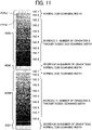
FIGS. 11 and12 . -
FIG. 11 is a diagram illustrating the gradation patches of the image forming apparatus according to the second embodiment of the present disclosure. -
FIG. 12 is a diagram illustrating a priority gradation determining process according to the second embodiment of the present disclosure. - In the present embodiment, the number of gradation patches P of priority color is increased, the number of gradation patches P of non-priority color is decreased, and the sub-scanning width of the gradation patches P of priority gradation is increased (thickened). Note that the operations in the present embodiment are performed according to a condition of whether the color is priority color or non-priority color and a condition of whether the gradation is priority gradation or non-priority gradation. However, the operations may be performed according to either one of these conditions.
- According to the present disclosure, the real-time printing performance of the image forming apparatus is enhanced.
- For example, among the colors of black (K), cyan (C), magenta (M), and yellow (Y), the colors of the gradation patches of the
gradation patch patterns FIG. 11 are priority colors based on the count values of the density values of each area in the table ofFIG. 12 . That is, the colors of the gradation patches of thegradation patch patterns gradation patch patterns gradation patch patterns - Then, the colors of black (K) and magenta (M), each having high gradation, are set to be priority gradations and the number of gradation patches P of priority gradations is increased. By so doing, the number of priority gradations is increased, and the sub-scanning widths of the priority gradations are set to be relatively thick (wide). Note that the normal sub-scanning width of the gradation patch in the table of
FIG. 12 is the same as the above-described reference patch width. - On the other hand, the colors of cyan and yellow are not priority colors and have no density. Due to the conditions, the number of gradation patches P of the color of cyan and the number of gradation patches P of the color of yellow are decreased. In this case, the difference in gradations of the gradation patches P of priority colors, which are black (K) and magenta (M), is smaller than difference in gradations of the gradation patches P of non-priority colors, which are cyan and yellow.
- As a result, the whole gradation patches P of the whole colors (i.e., the
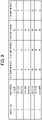
gradation patch patterns FIG. 11 are equal in the sub-scanning width to the gradation patches P of thegradation patch patterns - The relation of the gradation patches P of priority color, i.e., black and yellow, and the patch numbers (No) of classification of gradations is described in the table of
FIG. 12 . In this example, the gradation patches P corresponding to Nos. 3 and 4 in the table inFIG. 12 are respective two (multiple) gradation patches P having different gradation values from each other, as illustrated inFIG. 11 . By using multiple gradation patches P, the accuracy in detection and correction is more enhanced than the rest of the gradation patches P. - Next, a description is given of an image forming apparatus according to a third embodiment of the present disclosure, with reference to
FIG. 13 . -
FIG. 13 is a diagram illustrating gradation patches of an image forming apparatus according to the third embodiment of the present disclosure. - In the present embodiment, when the colors of cyan and yellow have no density as in the count results in the table in
FIG. 12 that is referred to in the second embodiment, the gradation patches of the colors of cyan and yellow are not formed. In other words, the configuration of the present embodiment does not form the gradation patches of non-priority colors, in other words, the gradation patches other than the gradation patches of priority colors. - According to the present disclosure, the real-time printing performance of the image forming apparatus is enhanced.
- Next, a description is given of an image forming apparatus according to a fourth embodiment of the present disclosure, with reference to
FIG. 14 . -
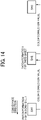
FIG. 14 is a diagram illustrating an operation performed by an image forming apparatus according to the fourth embodiment of the present disclosure. - In the present embodiment, the density information is acquired from the image information of the print image to be formed on a subsequent sheet, the sub-scanning width of each of the gradation patches P is determined from the acquired density information, and the gradation patches P having the sub-scanning widths different from each other are formed in the margin area SB of a preceding sheet.
- For example, when a first sheet SH1 is assumed to be a preceding sheet, the density information is acquired from the image information of a print image for a second sheet SH2 as a subsequent sheet. Then, the sub-scanning width of each of the gradation patches P included in the gradation patch patterns 400 is determined from the acquired density information, and the gradation patches P having the sub-scanning widths different from each other are formed in the margin areas SB of the sheet SH1 as a preceding sheet.
- Similarly, when the second sheet SH2 is a preceding sheet, the density information is acquired from the image information of a print image for a third sheet SH3 as a subsequent sheet. Then, the sub-scanning width of each of the gradation patches P included in the gradation patch patterns 400 is determined from the acquired density information, and the gradation patches P having the sub-scanning widths different from each other are formed in the margin areas SB of the second sheet SH2 as a preceding sheet.
- That is, in the present embodiment, a secondary conveyed sheet of two sheets to be consecutively conveyed is assumed as a "subsequent sheet" and the density information is acquired from the print information for the subsequent sheet to form the gradation patches on the preceding sheet.
- Then, the
inspection device 240 reads the gradation patch patterns 400 on the first sheet SH1 and the color correction value is calculated according to the reading result, so that the color correction is performed for forming an image based on the print information on the second sheet SH2. Similarly, theinspection device 240 reads the gradation patch patterns 400 on the second sheet SH2 and the color correction value is calculated according to the reading result, so that the color correction is performed for forming an image based on the print information on the third sheet SH3. - According to the present disclosure, the real-time printing performance of the image forming apparatus is enhanced.
- Next, a description is given of an image forming apparatus according to a fifth embodiment of the present disclosure, with reference to
FIGS. 15 and16 . -
FIG. 15 is a diagram illustrating an image forming apparatus according to the fifth embodiment of the present disclosure. -
FIG. 16 is a diagram illustrating an operation performed by the image forming apparatus according to the fifth embodiment of the present disclosure. - In the
image forming apparatus 200 according to the present embodiment, the sheet S that has passed theinspection device 240 is conveyed to thereversal passage 225 via theconveyance passage switcher 224. Theinspection device 240 includes theinline sensor 241 that reads one side of sheet S. - By providing the conveyance passage in the
image forming apparatus 200 having the above-described configuration, the gradation patch patterns 400 according to the fourth embodiment is achieved even when images are printed on both faces (first and second faces) of the sheet S. That is, as illustrated inFIG. 16 , when the first face of the first sheet SH1 is assumed to be a preceding sheet, the density information is acquired from the image information of a print image for the second face of the first sheet SH1 as a subsequent sheet. Then, the sub-scanning width of each of the gradation patches P included in the gradation patch patterns 400 is determined from the acquired density information, and the gradation patches P having the sub-scanning widths different from each other are formed in the margin areas SB of the first face of the first sheet SH1 as a preceding sheet. - After the image is formed on the first face of the first sheet SH1, the
inline sensor 241 reads the gradation patch patterns 400 on the first face of the first sheet SH1, and the first sheet SH1 is conveyed through theconveyance passage switcher 224 and thereversal passage 225 to form an image on the second face of the first sheet SH1. - At this time, assuming that the second face of the first sheet SH1 is assumed to be a preceding sheet and the first face of the second sheet SH2 is a subsequent sheet, the density information is acquired from the image information of a print image on the first face of the second sheet SH2 as in the above-described operation performed on the second face of the first sheet SH1 as a subsequent sheet. Then, the sub-scanning width of each of the gradation patches P included in the gradation patch patterns 400 is determined from the acquired density information, and the gradation patches P having the sub-scanning widths different from each other are formed in the margin areas SB of the second face of the first sheet SH1 as a preceding sheet.
- After the image is formed on the second face of the first sheet SH1, the
inline sensor 241 reads the gradation patch patterns 400 on the second face of the first sheet SH1, and the first sheet SH1 is ejected. - As described above, even when performing duplex printing, the image of the gradation patch patterns 400 are formed and corrected by assuming that, of two faces to be consecutively printed, the first printing face on which an image is printed first is assumed to be a preceding sheet and the second printing face on which an image is printed after the first printing face is assumed to be a subsequent sheet.
- Next, a description is given of an image forming apparatus according to the fifth embodiment of the present disclosure, with reference to
FIG. 17 . -
FIG. 17 is a diagram illustrating an operation performed by an image forming apparatus according to the fifth embodiment of the present disclosure. - In the present embodiment, the density information is acquired from the print information for a subsequent sheet that is two or more sheets away from the preceding sheet, so as to form the gradation patches P of the gradation patch patterns 400.
- For example, when the first sheet SH1 is assumed to be a preceding sheet, the density information is acquired from the image information of a print image for a fourth sheet SH4 as a subsequent sheet. The fourth sheet SH4 is three sheets after the preceding sheet. Then, the sub-scanning width of each of the gradation patches P included in the gradation patch patterns 400 is determined from the acquired density information, and the gradation patches P having the sub-scanning widths different from each other are formed in the margin areas SB of the first sheet SH1 as a preceding sheet.
- Similarly, when the second sheet SH2 is assumed to be a preceding sheet, the density information is acquired from the image information of a print image for a fifth sheet SH5 as a subsequent sheet. Then, the sub-scanning width of each of the gradation patches P included in the gradation patch patterns 400 is determined from the acquired density information, and the gradation patches P having the sub-scanning widths different from each other are formed in the margin areas SB of the second sheet SH2 as a preceding sheet.
- Similarly, when the third sheet SH3 and the fourth sheet SH4 are each assumed to be a preceding sheet, the density information is acquired from the image information of a print image for a sixth sheet SH6 and a seventh sheet SH7, respectively, as a subsequent sheet. Then, the sub-scanning width of each of the gradation patches P included in the gradation patch patterns 400 is determined from the acquired density information, and the gradation patches P having the sub-scanning widths different from each other are formed in the margin areas SB of the third sheet SH3 and the fourth sheet SH4, respectively, as a preceding sheet.
- Further, when the fifth sheet SH5, the sixth sheet SH6, and the seventh sheet SH7 are each assumed to be a preceding sheet, the density information is acquired from the image information of a print image for an eighth sheet, a ninth sheet, and a tenth sheet, respectively, as a subsequent sheet. Then, the sub-scanning width of each of the gradation patches P included in the gradation patch patterns 400 is determined from the acquired density information, and the gradation patches P having the sub-scanning widths different from each other are formed in the margin areas SB of the fifth sheet SH5, the sixth sheet SH6, and the seventh sheet SH7, respectively, as a preceding sheet.
- As described above, in this example, a sheet that is conveyed three sheets after the sheet S as a preceding sheet is assumed to be a subsequent sheet. Under this condition, the density information is acquired from the image information of a print image for a subsequent sheet, the sub-scanning width of each of the gradation patches P included in the gradation patch patterns 400 is determined from the acquired density information, and the gradation patches P are formed in the margin areas SB of the sheet S as a preceding sheet.
- In other words, in a similar manner to the fourth embodiment of the present disclosure as described above, when two sheets to be consecutively conveyed are assumed as a preceding sheet and a subsequent sheet, after the preceding sheet has reached the position of the
inspection device 240, the correction values for the subsequent sheet are calculated. Therefore, in order to reflect the color correction on the subsequent page, the normal printing speed is decreased, that is, the interval (sheet interval) between the consecutively conveyed sheets S is increased. As a result, the productivity of the image forming apparatus is likely to be lowered. - In order to address this inconvenience, the preceding sheet and the subsequent sheet are set to be consecutively conveyed at the intervals that do not decrease the productivity of the image forming apparatus. In the operation illustrated in
FIG. 17 , the gradation patches P for the fourth sheet SH4 formed on the first sheet SH1 are read to reflect the correction result on the fourth sheet SH4 without decreasing the productivity of the image forming apparatus. - Note that the operation of the present embodiment is not limited to the operation in which the subsequent sheet is set to be a sheet that is conveyed three sheets after preceding sheet (that is an expression of the preceding sheet + 3) as illustrated in
FIG. 17 but may include an operation in which the subsequent sheet satisfied the expression of (preceding sheet + m), where "m" is an integer of 2 or more. - As a result, the correction of an image on a sheet is performed without decreasing the productivity of the image forming apparatus, so that the color accuracy is obtained.
- Next, a description is given of a printing process of gradation patch executed by a controller, according to the sixth embodiment of the present disclosure, with reference to
FIG. 18 . -
FIG. 18 is a flowchart of a printing process of gradation patch pattern by the controller. - The printing process (image forming process) is turned on in response to execution of printing by a user, and the
controller 300 receives print data for the whole pages and sets the page number as N = 0 (S41). Then, thecontroller 300 determines whether there are print data for the (N+3)th page (S42). - When there are print data for the (N+3)th page (YES in S42), the
controller 300 analyses the print data for the (N+3)th page (S43), and determines the shape (patch shape) of the gradation patch patterns 400 to be printed on the (N+3)th page based on the analysis result (S44). - Then, the
controller 300 executes general image processing and color correction calculated from the reading result of the gradation patches P of the gradation patch patterns 400 by the inspection device 240 (S45). Note that, when "N" is 1, 2, or 3, thecontroller 300 performs default color correction. - Then, the print image (print data) for the (N)th page and the image (patch image) of the gradation patch patterns 400 for the (N+3)th page are printed (S46). In other words, the
controller 300 forms the print image for the (N)th page and the image of the gradation patches P having different widths from each other, of the gradation patch patterns 400 for the (N+3)th page. The gradation patch patterns 400 have the shape determined in step S44. - On the other hand, when there are no print data for the (N+3)th page (NO in S42), the
controller 300 sets patch OFF (S49), and then moves to step S45. - In this case, the
controller 300 executes regular image processing and color correction calculated from the reading result of the gradation patches P of the gradation patch patterns 400 by theinspection device 240 in steps S45 and S46 and does not form the gradation patches P when printing the print image (print data) for the (N)th page. - Thereafter, the
controller 300 determines whether the whole print images (whole pages) have been printed (S47). When the whole print pages have not been printed (NO in S47), the page of the print image is indicated as N = (N + 1) (S48) and the process goes back to step S42. On the other hand, when the whole print pages have been printed (YES in S47), the printing process of the flowchart ofFIG. 18 ends. - Next, a description is given of an image forming apparatus according to a seventh embodiment of the present disclosure, with reference to
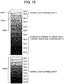
FIG. 19 . -
FIG. 19 is a diagram illustrating a gradation patch pattern of an image forming apparatus according to the seventh embodiment of the present disclosure. - In each of the above-described embodiments, the widths of the gradation patches P in one of the gradation patch patterns 400 are different from each other. On the other hand, for example, the widths of the
gradation patch patterns - For example, in the gradation patch patterns illustrated in
FIG. 19 , the width of the wholegradation patch pattern 400K (Nos. 1 to 9) for the color of yellow is set to be greater than the width of the wholegradation patch pattern 400M (Nos. 1 to 9) for the color of magenta. Note that, in this example inFIG. 19 , the number of gradations of thegradation patch pattern 400K is greater than the number of gradations of thegradation patch pattern 400M (400C and 400Y) or no gradation patch patterns 400 (400C and 400Y inFIG. 19 ) is formed. - Each of the above-described embodiments is not limited to the example of printing gradation patches on each sheet. For example, the gradation patch may be printed for each predetermined number of printed sheets. In a case in which gradation patches are formed per five (5) sheets, the gradation patches are formed on each preceding sheet based on the print image (print data) of the fifth sheet (for example, 10th sheet, 15th sheet) after the previous sheet having the gradation patches. In addition, when a print image (print data) satisfies a predetermined condition, the print image may be printed on a preceding sheet.
- The present disclosure is not limited to specific embodiments described above, and numerous additional modifications and variations are possible in light of the teachings within the technical scope of the appended claims. It is therefore to be understood that, the disclosure of this patent specification may be practiced otherwise by those skilled in the art than as specifically described herein, and such, modifications, alternatives are within the technical scope of the appended claims. Such embodiments and variations thereof are included in the scope and gist of the embodiments of the present disclosure and are included in the embodiments described in claims and the equivalent scope thereof.
- The effects described in the embodiments of this disclosure are listed as the examples of preferable effects derived from this disclosure, and therefore are not intended to limit to the embodiments of this disclosure.
- The embodiments described above are presented as an example to implement this disclosure. The embodiments described above are not intended to limit the scope of the invention. These novel embodiments can be implemented in various other forms, and various omissions, replacements, or changes can be made without departing from the gist of the invention. These embodiments and their variations are included in the scope and gist of this disclosure and are included in the scope of the invention recited in the claims and its equivalent.
- Any one of the above-described operations may be performed in various other ways, for example, in an order different from the one described above.
Claims (12)
- An image forming apparatus (200) comprising:an image forming device (210) configured to form an image on a sheet (S); anda control unit (300) configured to:acquire density information from image information of the image formed on the sheet (S);determine a width of each of a plurality of gradation patches (P) to be formed in a conveyance direction of the sheet (S) based on the density information; andcause the image forming device (210) to form the plurality of gradation patches (P) having different widths from each other in the conveyance direction of the sheet (S), in a margin area (SB, SC, SD) of the sheet (S).
- The image forming apparatus (200) according to claim 1,wherein the plurality of gradation patches (P) includes first gradation patches (P) each including a priority gradation and second gradation patches (P) each including a non-priority gradation that is not the priority gradation, andwherein a width of each of the first gradation patches (P) is greater than a width of each the second gradation patches (P).
- The image forming apparatus (200) according to claim 2,
wherein the control unit (300) is configured to define the priority gradation based on the image formed on the sheet (S) and a width of the margin area (SB, SC, SD) on the sheet (S). - The image forming apparatus (200) according to claim 3,
wherein print data on the gradation patches (P) formed per a given number of sheets (S) include data on the image formed on the sheet (S) and the width of the margin area (SB, SC, SD) on the sheet (S). - The image forming apparatus (200) according to claim 1 or 2,wherein the plurality of gradation patches (P) includes first gradation patches (P) of a priority color and second gradation patches (P) of a non-priority color that is not the priority color,wherein a difference in gradations of the first gradation patches (P) is smaller than a difference in gradations of the second gradation patches (P), andwherein a number of the first gradation patches (P) is greater than a number of the second gradation patches (P).
- The image forming apparatus (200) according to claim 1,wherein the plurality of gradation patches (P) includes first gradation patches (P) of a priority color and second gradation patches (P) of a non-priority color that is not the priority color, andwherein the control unit (300) is configured not to form the second gradation patches (P) of the non-priority color.
- The image forming apparatus (200) according to any one of claims 1 to 6, wherein adjacent gradation patches (P) in adjacent two different colors of gradation patches (P) of the plurality of gradation patches (P) have a smaller density difference in color than non-adjacent gradation patches (P) of a same color in the adjacent two different colors of gradation patches (P).
- The image forming apparatus (200) according to any one of claims 1 to 7, wherein the control unit (300) is configured to:acquire the density information from image information of an image to be formed on another sheet (SH2, SH3, SH4, SH5) that is conveyed after the sheet (S), andcause the image forming device (210) to form the plurality of gradation patches (P) on the sheet (SH1, SH2) based on the density information.
- The image forming apparatus (200) according to claim 8,
wherein the control unit (300) is configured to cause the image forming device (210) to form no gradation patch on the sheet (SH1, SH2) when there is no image to be formed on said another sheet (SH2, SH3, SH4, SH5). - The image forming apparatus (200) according to any one of claims 1 to 9, further comprising:a reader (240) configured to read the plurality of gradation patches (P) on the sheet (S),wherein the control unit (300) is configured to calculate a color correction value based on a reading result of the reader (240).
- A method of forming a plurality of gradation patches (P), the method comprising:acquiring (S13) density information from image information of an image formed on a sheet (S);determining a width of each of the plurality of gradation patches (P) to be formed in a conveyance direction of the sheet (S), based on the density information; andforming the plurality of gradation patches (P) having different widths from each other in the conveyance direction of the sheet (S), in a margin area (SB, SC, SD) of the sheet (S).
- An evaluation chart for an image forming apparatus (200), the evaluation chart comprising:a sheet (S);an image formed in an image area (SA) on the sheet (S) by the image forming apparatus (200); anda plurality of gradation patches (P) formed in an area outside the image area (SA) and having widths different from each other in a conveyance direction of the sheet (S).
Applications Claiming Priority (1)
| Application Number | Priority Date | Filing Date | Title |
|---|---|---|---|
| JP2021021358A JP7647143B2 (en) | 2021-02-13 | 2021-02-13 | Image forming apparatus, gradation patch forming method, and evaluation chart for image forming apparatus |
Publications (2)
| Publication Number | Publication Date |
|---|---|
| EP4044572A1 true EP4044572A1 (en) | 2022-08-17 |
| EP4044572B1 EP4044572B1 (en) | 2024-08-14 |
Family
ID=79185581
Family Applications (1)
| Application Number | Title | Priority Date | Filing Date |
|---|---|---|---|
| EP21218313.1A Active EP4044572B1 (en) | 2021-02-13 | 2021-12-30 | Image forming apparatus, method of forming gradation patch, and evaluation chart of the image forming apparatus |
Country Status (3)
| Country | Link |
|---|---|
| US (1) | US20220263972A1 (en) |
| EP (1) | EP4044572B1 (en) |
| JP (1) | JP7647143B2 (en) |
Families Citing this family (2)
| Publication number | Priority date | Publication date | Assignee | Title |
|---|---|---|---|---|
| JP7610393B2 (en) * | 2020-11-02 | 2025-01-08 | キヤノン株式会社 | Image forming device |
| JP2024110513A (en) | 2023-02-03 | 2024-08-16 | 株式会社リコー | Information processing device, information processing system, information processing method, and program |
Citations (5)
| Publication number | Priority date | Publication date | Assignee | Title |
|---|---|---|---|---|
| US20070002344A1 (en) * | 2005-06-30 | 2007-01-04 | Xerox Corporation | Color characterization or calibration targets with noise-dependent patch size or number |
| JP2018005173A (en) | 2016-07-08 | 2018-01-11 | コニカミノルタ株式会社 | Image forming apparatus and program |
| US20180338067A1 (en) * | 2017-05-18 | 2018-11-22 | Konica Minolta, Inc. | Color value correction control method, color value correction control program, and image forming apparatus |
| JP2019014051A (en) * | 2017-07-03 | 2019-01-31 | キヤノン株式会社 | Image processing apparatus, image forming apparatus, and program |
| US20190268502A1 (en) * | 2018-02-26 | 2019-08-29 | Ricoh Company, Ltd. | Color tone control device and image forming apparatus |
Family Cites Families (7)
| Publication number | Priority date | Publication date | Assignee | Title |
|---|---|---|---|---|
| JP3934473B2 (en) * | 2002-05-09 | 2007-06-20 | 大日本スクリーン製造株式会社 | Patch measuring device and printing device incorporating the same |
| US7652791B2 (en) * | 2006-05-16 | 2010-01-26 | Xerox Corporation | Reprinting |
| US7548705B2 (en) * | 2007-04-03 | 2009-06-16 | Xerox Corporation | Systems and methods for marking test patches for calibrating and/or visually confirming color accuracy of a marking device |
| JP5751812B2 (en) | 2009-12-22 | 2015-07-22 | キヤノン株式会社 | Image processing system, image processing method, and printed matter |
| US10282645B2 (en) * | 2017-06-26 | 2019-05-07 | Konica Minolta Laboratory U.S.A., Inc. | Color patch layout determination |
| JP7379147B2 (en) * | 2019-12-25 | 2023-11-14 | キヤノン株式会社 | Image forming device, image forming method, and program |
| JP7610393B2 (en) * | 2020-11-02 | 2025-01-08 | キヤノン株式会社 | Image forming device |
-
2021
- 2021-02-13 JP JP2021021358A patent/JP7647143B2/en active Active
- 2021-12-30 EP EP21218313.1A patent/EP4044572B1/en active Active
-
2022
- 2022-01-07 US US17/570,904 patent/US20220263972A1/en not_active Abandoned
Patent Citations (5)
| Publication number | Priority date | Publication date | Assignee | Title |
|---|---|---|---|---|
| US20070002344A1 (en) * | 2005-06-30 | 2007-01-04 | Xerox Corporation | Color characterization or calibration targets with noise-dependent patch size or number |
| JP2018005173A (en) | 2016-07-08 | 2018-01-11 | コニカミノルタ株式会社 | Image forming apparatus and program |
| US20180338067A1 (en) * | 2017-05-18 | 2018-11-22 | Konica Minolta, Inc. | Color value correction control method, color value correction control program, and image forming apparatus |
| JP2019014051A (en) * | 2017-07-03 | 2019-01-31 | キヤノン株式会社 | Image processing apparatus, image forming apparatus, and program |
| US20190268502A1 (en) * | 2018-02-26 | 2019-08-29 | Ricoh Company, Ltd. | Color tone control device and image forming apparatus |
Also Published As
| Publication number | Publication date |
|---|---|
| JP2022123899A (en) | 2022-08-25 |
| US20220263972A1 (en) | 2022-08-18 |
| JP7647143B2 (en) | 2025-03-18 |
| EP4044572B1 (en) | 2024-08-14 |
Similar Documents
| Publication | Publication Date | Title |
|---|---|---|
| US8780378B2 (en) | Inspection apparatus, inspection method, inspection system, and storage medium | |
| JP7600446B2 (en) | Image forming device | |
| EP2141547A1 (en) | Color Image Forming Apparatus and Control Method of the Same | |
| CN110086950B (en) | Image reading apparatus, image forming apparatus, and density correction method | |
| US20140160534A1 (en) | Image processing method, image forming apparatus and image forming system | |
| US10877420B2 (en) | Image forming apparatus having correction of following image based on deformation of preceding recording medium | |
| US10200565B2 (en) | Image forming system and reading device | |
| US20250208552A1 (en) | Image forming apparatus | |
| EP4044572B1 (en) | Image forming apparatus, method of forming gradation patch, and evaluation chart of the image forming apparatus | |
| US10264162B2 (en) | Image forming system, image reading apparatus, and image forming apparatus including means for determining a temperature distribution in a paper medium | |
| EP2565717B1 (en) | Image forming apparatus | |
| US20220004138A1 (en) | Curling detection device, image forming apparatus, and curling detection method | |
| JP2014231402A (en) | Image formation device and paper deformation correction method | |
| US20260106946A1 (en) | Image forming apparatus and storage medium | |
| US10021252B2 (en) | Image reading device and image forming system | |
| US12323562B2 (en) | Adjust a position of an image to be formed on a sheet based on reading a chart | |
| US20240377780A1 (en) | Image forming apparatus and recording medium | |
| US20240323289A1 (en) | Image reading apparatus and image forming apparatus | |
| US20240380858A1 (en) | Image forming apparatus, recording medium, and chart | |
| WO2024252936A1 (en) | Image reading device and image forming apparatus | |
| JP2006109408A (en) | Image reading apparatus adjustment method, image reading apparatus and image forming apparatus using the same | |
| US11483450B2 (en) | Image forming apparatus and image reading apparatus | |
| JP2024154324A (en) | Image processing device, image reading device, image forming device, and image processing method | |
| JP5194407B2 (en) | Image signal processing apparatus, image forming apparatus, image signal processing method, program, and recording medium | |
| JP2011188487A (en) | Image processor |
Legal Events
| Date | Code | Title | Description |
|---|---|---|---|
| PUAI | Public reference made under article 153(3) epc to a published international application that has entered the european phase |
Free format text: ORIGINAL CODE: 0009012 |
|
| STAA | Information on the status of an ep patent application or granted ep patent |
Free format text: STATUS: REQUEST FOR EXAMINATION WAS MADE |
|
| 17P | Request for examination filed |
Effective date: 20211230 |
|
| AK | Designated contracting states |
Kind code of ref document: A1 Designated state(s): AL AT BE BG CH CY CZ DE DK EE ES FI FR GB GR HR HU IE IS IT LI LT LU LV MC MK MT NL NO PL PT RO RS SE SI SK SM TR |
|
| STAA | Information on the status of an ep patent application or granted ep patent |
Free format text: STATUS: EXAMINATION IS IN PROGRESS |
|
| 17Q | First examination report despatched |
Effective date: 20230814 |
|
| GRAP | Despatch of communication of intention to grant a patent |
Free format text: ORIGINAL CODE: EPIDOSNIGR1 |
|
| STAA | Information on the status of an ep patent application or granted ep patent |
Free format text: STATUS: GRANT OF PATENT IS INTENDED |
|
| RIC1 | Information provided on ipc code assigned before grant |
Ipc: G06K 15/00 20060101ALI20240327BHEP Ipc: G06K 15/02 20060101ALI20240327BHEP Ipc: H04N 1/60 20060101AFI20240327BHEP |
|
| INTG | Intention to grant announced |
Effective date: 20240418 |
|
| GRAS | Grant fee paid |
Free format text: ORIGINAL CODE: EPIDOSNIGR3 |
|
| GRAA | (expected) grant |
Free format text: ORIGINAL CODE: 0009210 |
|
| STAA | Information on the status of an ep patent application or granted ep patent |
Free format text: STATUS: THE PATENT HAS BEEN GRANTED |
|
| P01 | Opt-out of the competence of the unified patent court (upc) registered |
Free format text: CASE NUMBER: APP_36569/2024 Effective date: 20240619 |
|
| AK | Designated contracting states |
Kind code of ref document: B1 Designated state(s): AL AT BE BG CH CY CZ DE DK EE ES FI FR GB GR HR HU IE IS IT LI LT LU LV MC MK MT NL NO PL PT RO RS SE SI SK SM TR |
|
| REG | Reference to a national code |
Ref country code: GB Ref legal event code: FG4D |
|
| REG | Reference to a national code |
Ref country code: CH Ref legal event code: EP |
|
| REG | Reference to a national code |
Ref country code: DE Ref legal event code: R096 Ref document number: 602021017170 Country of ref document: DE |
|
| REG | Reference to a national code |
Ref country code: IE Ref legal event code: FG4D |
|
| REG | Reference to a national code |
Ref country code: LT Ref legal event code: MG9D |
|
| REG | Reference to a national code |
Ref country code: NL Ref legal event code: MP Effective date: 20240814 |
|
| PG25 | Lapsed in a contracting state [announced via postgrant information from national office to epo] |
Ref country code: NO Free format text: LAPSE BECAUSE OF FAILURE TO SUBMIT A TRANSLATION OF THE DESCRIPTION OR TO PAY THE FEE WITHIN THE PRESCRIBED TIME-LIMIT Effective date: 20241114 |
|
| REG | Reference to a national code |
Ref country code: AT Ref legal event code: MK05 Ref document number: 1714340 Country of ref document: AT Kind code of ref document: T Effective date: 20240814 |
|
| PG25 | Lapsed in a contracting state [announced via postgrant information from national office to epo] |
Ref country code: FI Free format text: LAPSE BECAUSE OF FAILURE TO SUBMIT A TRANSLATION OF THE DESCRIPTION OR TO PAY THE FEE WITHIN THE PRESCRIBED TIME-LIMIT Effective date: 20240814 Ref country code: NL Free format text: LAPSE BECAUSE OF FAILURE TO SUBMIT A TRANSLATION OF THE DESCRIPTION OR TO PAY THE FEE WITHIN THE PRESCRIBED TIME-LIMIT Effective date: 20240814 Ref country code: PL Free format text: LAPSE BECAUSE OF FAILURE TO SUBMIT A TRANSLATION OF THE DESCRIPTION OR TO PAY THE FEE WITHIN THE PRESCRIBED TIME-LIMIT Effective date: 20240814 Ref country code: PT Free format text: LAPSE BECAUSE OF FAILURE TO SUBMIT A TRANSLATION OF THE DESCRIPTION OR TO PAY THE FEE WITHIN THE PRESCRIBED TIME-LIMIT Effective date: 20241216 Ref country code: GR Free format text: LAPSE BECAUSE OF FAILURE TO SUBMIT A TRANSLATION OF THE DESCRIPTION OR TO PAY THE FEE WITHIN THE PRESCRIBED TIME-LIMIT Effective date: 20241115 |
|
| PG25 | Lapsed in a contracting state [announced via postgrant information from national office to epo] |
Ref country code: BG Free format text: LAPSE BECAUSE OF FAILURE TO SUBMIT A TRANSLATION OF THE DESCRIPTION OR TO PAY THE FEE WITHIN THE PRESCRIBED TIME-LIMIT Effective date: 20240814 |
|
| PG25 | Lapsed in a contracting state [announced via postgrant information from national office to epo] |
Ref country code: LV Free format text: LAPSE BECAUSE OF FAILURE TO SUBMIT A TRANSLATION OF THE DESCRIPTION OR TO PAY THE FEE WITHIN THE PRESCRIBED TIME-LIMIT Effective date: 20240814 |
|
| PG25 | Lapsed in a contracting state [announced via postgrant information from national office to epo] |
Ref country code: AT Free format text: LAPSE BECAUSE OF FAILURE TO SUBMIT A TRANSLATION OF THE DESCRIPTION OR TO PAY THE FEE WITHIN THE PRESCRIBED TIME-LIMIT Effective date: 20240814 Ref country code: IS Free format text: LAPSE BECAUSE OF FAILURE TO SUBMIT A TRANSLATION OF THE DESCRIPTION OR TO PAY THE FEE WITHIN THE PRESCRIBED TIME-LIMIT Effective date: 20241214 |
|
| PG25 | Lapsed in a contracting state [announced via postgrant information from national office to epo] |
Ref country code: HR Free format text: LAPSE BECAUSE OF FAILURE TO SUBMIT A TRANSLATION OF THE DESCRIPTION OR TO PAY THE FEE WITHIN THE PRESCRIBED TIME-LIMIT Effective date: 20240814 |
|
| PG25 | Lapsed in a contracting state [announced via postgrant information from national office to epo] |
Ref country code: RS Free format text: LAPSE BECAUSE OF FAILURE TO SUBMIT A TRANSLATION OF THE DESCRIPTION OR TO PAY THE FEE WITHIN THE PRESCRIBED TIME-LIMIT Effective date: 20241114 Ref country code: ES Free format text: LAPSE BECAUSE OF FAILURE TO SUBMIT A TRANSLATION OF THE DESCRIPTION OR TO PAY THE FEE WITHIN THE PRESCRIBED TIME-LIMIT Effective date: 20240814 |
|
| PG25 | Lapsed in a contracting state [announced via postgrant information from national office to epo] |
Ref country code: RS Free format text: LAPSE BECAUSE OF FAILURE TO SUBMIT A TRANSLATION OF THE DESCRIPTION OR TO PAY THE FEE WITHIN THE PRESCRIBED TIME-LIMIT Effective date: 20241114 Ref country code: PT Free format text: LAPSE BECAUSE OF FAILURE TO SUBMIT A TRANSLATION OF THE DESCRIPTION OR TO PAY THE FEE WITHIN THE PRESCRIBED TIME-LIMIT Effective date: 20241216 Ref country code: PL Free format text: LAPSE BECAUSE OF FAILURE TO SUBMIT A TRANSLATION OF THE DESCRIPTION OR TO PAY THE FEE WITHIN THE PRESCRIBED TIME-LIMIT Effective date: 20240814 Ref country code: NO Free format text: LAPSE BECAUSE OF FAILURE TO SUBMIT A TRANSLATION OF THE DESCRIPTION OR TO PAY THE FEE WITHIN THE PRESCRIBED TIME-LIMIT Effective date: 20241114 Ref country code: NL Free format text: LAPSE BECAUSE OF FAILURE TO SUBMIT A TRANSLATION OF THE DESCRIPTION OR TO PAY THE FEE WITHIN THE PRESCRIBED TIME-LIMIT Effective date: 20240814 Ref country code: LV Free format text: LAPSE BECAUSE OF FAILURE TO SUBMIT A TRANSLATION OF THE DESCRIPTION OR TO PAY THE FEE WITHIN THE PRESCRIBED TIME-LIMIT Effective date: 20240814 Ref country code: IS Free format text: LAPSE BECAUSE OF FAILURE TO SUBMIT A TRANSLATION OF THE DESCRIPTION OR TO PAY THE FEE WITHIN THE PRESCRIBED TIME-LIMIT Effective date: 20241214 Ref country code: HR Free format text: LAPSE BECAUSE OF FAILURE TO SUBMIT A TRANSLATION OF THE DESCRIPTION OR TO PAY THE FEE WITHIN THE PRESCRIBED TIME-LIMIT Effective date: 20240814 Ref country code: GR Free format text: LAPSE BECAUSE OF FAILURE TO SUBMIT A TRANSLATION OF THE DESCRIPTION OR TO PAY THE FEE WITHIN THE PRESCRIBED TIME-LIMIT Effective date: 20241115 Ref country code: FI Free format text: LAPSE BECAUSE OF FAILURE TO SUBMIT A TRANSLATION OF THE DESCRIPTION OR TO PAY THE FEE WITHIN THE PRESCRIBED TIME-LIMIT Effective date: 20240814 Ref country code: ES Free format text: LAPSE BECAUSE OF FAILURE TO SUBMIT A TRANSLATION OF THE DESCRIPTION OR TO PAY THE FEE WITHIN THE PRESCRIBED TIME-LIMIT Effective date: 20240814 Ref country code: BG Free format text: LAPSE BECAUSE OF FAILURE TO SUBMIT A TRANSLATION OF THE DESCRIPTION OR TO PAY THE FEE WITHIN THE PRESCRIBED TIME-LIMIT Effective date: 20240814 Ref country code: AT Free format text: LAPSE BECAUSE OF FAILURE TO SUBMIT A TRANSLATION OF THE DESCRIPTION OR TO PAY THE FEE WITHIN THE PRESCRIBED TIME-LIMIT Effective date: 20240814 |
|
| PG25 | Lapsed in a contracting state [announced via postgrant information from national office to epo] |
Ref country code: SM Free format text: LAPSE BECAUSE OF FAILURE TO SUBMIT A TRANSLATION OF THE DESCRIPTION OR TO PAY THE FEE WITHIN THE PRESCRIBED TIME-LIMIT Effective date: 20240814 Ref country code: RO Free format text: LAPSE BECAUSE OF FAILURE TO SUBMIT A TRANSLATION OF THE DESCRIPTION OR TO PAY THE FEE WITHIN THE PRESCRIBED TIME-LIMIT Effective date: 20240814 Ref country code: DK Free format text: LAPSE BECAUSE OF FAILURE TO SUBMIT A TRANSLATION OF THE DESCRIPTION OR TO PAY THE FEE WITHIN THE PRESCRIBED TIME-LIMIT Effective date: 20240814 |
|
| PG25 | Lapsed in a contracting state [announced via postgrant information from national office to epo] |
Ref country code: EE Free format text: LAPSE BECAUSE OF FAILURE TO SUBMIT A TRANSLATION OF THE DESCRIPTION OR TO PAY THE FEE WITHIN THE PRESCRIBED TIME-LIMIT Effective date: 20240814 |
|
| PG25 | Lapsed in a contracting state [announced via postgrant information from national office to epo] |
Ref country code: CZ Free format text: LAPSE BECAUSE OF FAILURE TO SUBMIT A TRANSLATION OF THE DESCRIPTION OR TO PAY THE FEE WITHIN THE PRESCRIBED TIME-LIMIT Effective date: 20240814 |
|
| PG25 | Lapsed in a contracting state [announced via postgrant information from national office to epo] |
Ref country code: IT Free format text: LAPSE BECAUSE OF FAILURE TO SUBMIT A TRANSLATION OF THE DESCRIPTION OR TO PAY THE FEE WITHIN THE PRESCRIBED TIME-LIMIT Effective date: 20240814 Ref country code: SK Free format text: LAPSE BECAUSE OF FAILURE TO SUBMIT A TRANSLATION OF THE DESCRIPTION OR TO PAY THE FEE WITHIN THE PRESCRIBED TIME-LIMIT Effective date: 20240814 |
|
| REG | Reference to a national code |
Ref country code: DE Ref legal event code: R097 Ref document number: 602021017170 Country of ref document: DE |
|
| PLBE | No opposition filed within time limit |
Free format text: ORIGINAL CODE: 0009261 |
|
| STAA | Information on the status of an ep patent application or granted ep patent |
Free format text: STATUS: NO OPPOSITION FILED WITHIN TIME LIMIT |
|
| PG25 | Lapsed in a contracting state [announced via postgrant information from national office to epo] |
Ref country code: MC Free format text: LAPSE BECAUSE OF FAILURE TO SUBMIT A TRANSLATION OF THE DESCRIPTION OR TO PAY THE FEE WITHIN THE PRESCRIBED TIME-LIMIT Effective date: 20240814 |
|
| 26N | No opposition filed |
Effective date: 20250515 |
|
| REG | Reference to a national code |
Ref country code: CH Ref legal event code: PL |
|
| PG25 | Lapsed in a contracting state [announced via postgrant information from national office to epo] |
Ref country code: LU Free format text: LAPSE BECAUSE OF NON-PAYMENT OF DUE FEES Effective date: 20241230 |
|
| PG25 | Lapsed in a contracting state [announced via postgrant information from national office to epo] |
Ref country code: SE Free format text: LAPSE BECAUSE OF FAILURE TO SUBMIT A TRANSLATION OF THE DESCRIPTION OR TO PAY THE FEE WITHIN THE PRESCRIBED TIME-LIMIT Effective date: 20240814 |
|
| REG | Reference to a national code |
Ref country code: BE Ref legal event code: MM Effective date: 20241231 |
|
| PG25 | Lapsed in a contracting state [announced via postgrant information from national office to epo] |
Ref country code: BE Free format text: LAPSE BECAUSE OF NON-PAYMENT OF DUE FEES Effective date: 20241231 |
|
| PG25 | Lapsed in a contracting state [announced via postgrant information from national office to epo] |
Ref country code: CH Free format text: LAPSE BECAUSE OF NON-PAYMENT OF DUE FEES Effective date: 20241231 |
|
| PG25 | Lapsed in a contracting state [announced via postgrant information from national office to epo] |
Ref country code: IE Free format text: LAPSE BECAUSE OF NON-PAYMENT OF DUE FEES Effective date: 20241230 |
|
| PGFP | Annual fee paid to national office [announced via postgrant information from national office to epo] |
Ref country code: DE Payment date: 20251211 Year of fee payment: 5 |
|
| PGFP | Annual fee paid to national office [announced via postgrant information from national office to epo] |
Ref country code: GB Payment date: 20251219 Year of fee payment: 5 |
|
| PGFP | Annual fee paid to national office [announced via postgrant information from national office to epo] |
Ref country code: FR Payment date: 20251229 Year of fee payment: 5 |
|
| PG25 | Lapsed in a contracting state [announced via postgrant information from national office to epo] |
Ref country code: CY Free format text: LAPSE BECAUSE OF FAILURE TO SUBMIT A TRANSLATION OF THE DESCRIPTION OR TO PAY THE FEE WITHIN THE PRESCRIBED TIME-LIMIT Effective date: 20240814 |