EP4044412A1 - Rotor for rotating electrical machine - Google Patents
Rotor for rotating electrical machine Download PDFInfo
- Publication number
- EP4044412A1 EP4044412A1 EP20873562.1A EP20873562A EP4044412A1 EP 4044412 A1 EP4044412 A1 EP 4044412A1 EP 20873562 A EP20873562 A EP 20873562A EP 4044412 A1 EP4044412 A1 EP 4044412A1
- Authority
- EP
- European Patent Office
- Prior art keywords
- rotor
- bar
- groove
- axial direction
- swage
- Prior art date
- Legal status (The legal status is an assumption and is not a legal conclusion. Google has not performed a legal analysis and makes no representation as to the accuracy of the status listed.)
- Pending
Links
Images




Classifications
-
- H—ELECTRICITY
- H02—GENERATION; CONVERSION OR DISTRIBUTION OF ELECTRIC POWER
- H02K—DYNAMO-ELECTRIC MACHINES
- H02K1/00—Details of the magnetic circuit
- H02K1/06—Details of the magnetic circuit characterised by the shape, form or construction
-
- H—ELECTRICITY
- H02—GENERATION; CONVERSION OR DISTRIBUTION OF ELECTRIC POWER
- H02K—DYNAMO-ELECTRIC MACHINES
- H02K1/00—Details of the magnetic circuit
- H02K1/06—Details of the magnetic circuit characterised by the shape, form or construction
- H02K1/22—Rotating parts of the magnetic circuit
-
- H—ELECTRICITY
- H02—GENERATION; CONVERSION OR DISTRIBUTION OF ELECTRIC POWER
- H02K—DYNAMO-ELECTRIC MACHINES
- H02K1/00—Details of the magnetic circuit
- H02K1/06—Details of the magnetic circuit characterised by the shape, form or construction
- H02K1/22—Rotating parts of the magnetic circuit
- H02K1/26—Rotor cores with slots for windings
- H02K1/265—Shape, form or location of the slots
-
- H—ELECTRICITY
- H02—GENERATION; CONVERSION OR DISTRIBUTION OF ELECTRIC POWER
- H02K—DYNAMO-ELECTRIC MACHINES
- H02K15/00—Processes or apparatus specially adapted for manufacturing, assembling, maintaining or repairing of dynamo-electric machines
- H02K15/02—Processes or apparatus specially adapted for manufacturing, assembling, maintaining or repairing of dynamo-electric machines of stator or rotor bodies
-
- H—ELECTRICITY
- H02—GENERATION; CONVERSION OR DISTRIBUTION OF ELECTRIC POWER
- H02K—DYNAMO-ELECTRIC MACHINES
- H02K15/00—Processes or apparatus specially adapted for manufacturing, assembling, maintaining or repairing of dynamo-electric machines
- H02K15/02—Processes or apparatus specially adapted for manufacturing, assembling, maintaining or repairing of dynamo-electric machines of stator or rotor bodies
- H02K15/021—Magnetic cores
- H02K15/023—Cage rotors
-
- H—ELECTRICITY
- H02—GENERATION; CONVERSION OR DISTRIBUTION OF ELECTRIC POWER
- H02K—DYNAMO-ELECTRIC MACHINES
- H02K17/00—Asynchronous induction motors; Asynchronous induction generators
- H02K17/02—Asynchronous induction motors
- H02K17/16—Asynchronous induction motors having rotors with internally short-circuited windings, e.g. cage rotors
-
- H—ELECTRICITY
- H02—GENERATION; CONVERSION OR DISTRIBUTION OF ELECTRIC POWER
- H02K—DYNAMO-ELECTRIC MACHINES
- H02K17/00—Asynchronous induction motors; Asynchronous induction generators
- H02K17/02—Asynchronous induction motors
- H02K17/34—Cascade arrangement of an asynchronous motor with another dynamo-electric motor or converter
- H02K17/40—Cascade arrangement of an asynchronous motor with another dynamo-electric motor or converter with a rotary AC/DC converter
-
- H—ELECTRICITY
- H02—GENERATION; CONVERSION OR DISTRIBUTION OF ELECTRIC POWER
- H02K—DYNAMO-ELECTRIC MACHINES
- H02K3/00—Details of windings
- H02K3/04—Windings characterised by the conductor shape, form or construction, e.g. with bar conductors
- H02K3/24—Windings characterised by the conductor shape, form or construction, e.g. with bar conductors with channels or ducts for cooling medium between the conductors
-
- H—ELECTRICITY
- H02—GENERATION; CONVERSION OR DISTRIBUTION OF ELECTRIC POWER
- H02K—DYNAMO-ELECTRIC MACHINES
- H02K9/00—Arrangements for cooling or ventilating
-
- H—ELECTRICITY
- H02—GENERATION; CONVERSION OR DISTRIBUTION OF ELECTRIC POWER
- H02K—DYNAMO-ELECTRIC MACHINES
- H02K9/00—Arrangements for cooling or ventilating
- H02K9/02—Arrangements for cooling or ventilating by ambient air flowing through the machine
-
- H—ELECTRICITY
- H02—GENERATION; CONVERSION OR DISTRIBUTION OF ELECTRIC POWER
- H02K—DYNAMO-ELECTRIC MACHINES
- H02K9/00—Arrangements for cooling or ventilating
- H02K9/08—Arrangements for cooling or ventilating by gaseous cooling medium circulating wholly within the machine casing
-
- H—ELECTRICITY
- H02—GENERATION; CONVERSION OR DISTRIBUTION OF ELECTRIC POWER
- H02K—DYNAMO-ELECTRIC MACHINES
- H02K2213/00—Specific aspects, not otherwise provided for and not covered by codes H02K2201/00 - H02K2211/00
- H02K2213/03—Machines characterised by numerical values, ranges, mathematical expressions or similar information
Definitions
- Embodiments of the present application relate generally to a rotor of a rotary electric machine with rotor bars.
- an induction motor with a caged rotor structure As an example of rotary electric machines, an induction motor with a caged rotor structure is known.
- the caged rotor includes a rotor iron core, a plurality of rotor bars embedded in the rotor iron core, and an end ring connecting the rotor bars outside the rotor iron core.
- the rotor bar is inserted into a slot provided with the rotor iron core. Both ends of the rotor bar in the axial direction (bar ends) protrude outward from the both end surfaces of the rotor iron core.
- a swage treatment to the rotor bars, that is, for example, by forming swage grooves in the rotor bars, the rotor bars are fixed to the slots of the rotor iron core. Normally, the swage groove is formed within a range of the rotor iron core, and is not formed in the bar end.
- Patent Literature 1 JP H11-18344 A
- the embodiments of the present application aim to present a rotor of a rotary electric machine which can improve the cooling performance.
- a rotor of a rotary electric machine comprises: a rotational shaft which is rotatable about a central axis; a rotator core coaxially fixed to the rotational shaft, the rotator core including a first end surface positioned on one end side in an axial direction and a second end surface positioned on the other end side in the axial direction, an outer peripheral surface which is coaxial with the central axis, a plurality of slots each formed to passing therethrough in the axial direction, opening on the first and second end surfaces, disposed at intervals in a circumferential direction of the outer peripheral surface, and a plurality of openings each formed in the outer peripheral surface, extending in the axial direction, and communicating with the slot; a plurality of rotor bars each inserted through the slot, and including a first bar end extending from the first end surface in the axial direction and a second bar end extending from the second end surface in the axial direction; a first annular end ring fixed to extending ends of the
- Each of the rotor bars includes a swage groove extending in the axial direction to be opposed to the opening, and a first end swage groove formed in the first bar end continuously to the swage groove, and the first end swage groove extends from the position of the first end surface toward the first end ring with being inclined to an outside in a radial direction of the rotator core.
- FIG. 1 is a vertical cross-sectional view of a rotary electric machine of an embodiment, which illustrates the rotary electric machine divided half along the central axis thereof.
- a rotary electric machine 10 is configured as, for example, an inner rotor type rotary electric machine.
- the rotary electric machine 10 includes an internally sealed case 12, stator 14 arranged inside the case 12, and cage-type rotor 16.
- the case 12 includes a substantially cylindrical frame 18, disk-shaped first bracket 19 attached to one end of the frame 18 in the axial direction in a manner to close the end, and disk-shaped second bracket 20 attached to the other axial end of the frame 18 in a manner to close the other end.
- a first bearing housing 22a which incorporates a bearing B1 is bolted.
- a second bearing housing 22b which incorporates a bearing B2 is bolted.
- the bearings B1 and B2 are aligned along the central axis C1 of the rotary electric machine 10.
- the stator 14 has a cylindrical stator iron core 24 and a stator coils wound around the stator iron core 24.
- the stator iron core 24 is supported by the frame 18 with its outer peripheral surface engaged with the inner peripheral surface of the frame 18, and is arranged coaxially with the central axis C1.
- a pair of annular iron core holders 26a, 26b are fixed to both axial surfaces of the stator iron core 24.
- the stator iron core 24 includes a number of laminated annular metal plates formed of magnetic material, for example, silicon steel plate.
- a plurality of slots, each extending in the axial direction, are formed in the inner circumference of the stator iron core 24.
- the stator coil 28 is embedded in the slots and attached to the stator iron core 24. The coil ends 28e of the stator coil 28 extend in the axial direction from both ends of the stator iron core 24.
- the rotor 16 includes a rotational shaft 30, rotor core (rotor iron core) 32, a plurality of rotor bars 40 embedded in the rotor iron core 32, and a pair of end rings 42a and 42b connected to the rotor bars 40 at both ends.
- the rotational shaft 30 is disposed in the case 12 coaxially with the central axis C1, and is rotatably supported by the bearings B1 and B2 at the one end and the other end thereof in the axial direction, respectively.
- a drive side end 30a of the rotational shaft 30 extends outside the machine.
- a coupling for connecting a drive gear device, etc., is attached to the drive side end 30a.
- the rotor iron core 32 includes a number of annular metal plates made of magnetic material, for example, silicon steel plate, laminated together to form a substantially cylindrical shape.
- the rotor iron core 32 is mounted in the approximate center of the rotational shaft 30 in the axial direction, and is located inside the stator iron core 24, coaxially with the central axis C1.
- the outer periphery of the rotor iron core 32 faces the inner periphery of the stator iron core 24 with a gap G.
- the axial length of the rotor iron core 32 is substantially equal to the axial length of the stator iron core 24.
- the rotor iron core 32 has a first end face 32a located at one end in the axial direction and a second end face 32b located at the other end in the axial direction.
- the first end face 32a and the second end face 32b extend in a manner to be substantially perpendicular to the central axis C1.
- the rotor iron core 32 is supported on the rotational shaft 30 by a pair of iron core supports 34a, 34b such that it is sandwiched from both ends in the axial direction.
- the iron core support plates 34a and 34b are formed in an annular shape, and their outer diameter is smaller than the outer diameter of the rotor iron core 32.
- FIG. 2 is a cross-sectional view of the rotor, taken along line A-A in FIG. 1
- FIG. 4 is an enlarged cross-sectional view of the rotor bar portion of the rotor.
- a plurality of ventilation ducts 44 are formed in the rotor iron core 32 and the iron core pushers 34a and 34b, penetrating through them in the axial direction.
- the ventilation ducts 44 are provided at regular intervals in the circumferential direction around the central axis C1.
- a plurality of slots (grooves) 50 are formed on the outer periphery of the rotor iron core 32, each extending in the axial direction and arranged at regular intervals in the circumferential direction.
- Each slot 50 extends through the rotor iron core 32 in the axial direction, and opens in the first end surface 32 and the second end surface 32b.
- Each slot 50 also opens to the outer circumference of the rotor iron core 32 through an opening 52 having a circumferential width W2.
- the opening 52 extends over the entire axial length of the rotor iron core 32.
- the cross-sectional shape of the slot 50 is, for example, a rectangular shape.
- the circumferential width W1 of the slot 50 is set to be larger than the circumferential width W2 of the opening 52.
- the rotor bar 40 is inserted into each slot 50, and extends in the axial direction of the rotor iron core 32.
- the cross-sectional shape of the rotor bar 40 is, for example, formed in a rectangular shape with a size (dimension) corresponding to the cross-sectional shape of the slot 50.
- the rotor bar 40 has a pair of short side surfaces (upper surface 41a and lower surface 41b) and a pair of long side surfaces (a pair of side surfaces 41c) opposed to each other.
- the rotor bar 40 is disposed in the slot 50 such that the top surface 41a faces the outer peripheral surface of the rotor iron core 32, that is, the top surface 41a is opposed to the opening 52.
- one longitudinal end 40a of the rotor bar 40 extends outward from the first end surface 32a of the rotor iron core 32.
- the other longitudinal end 40b of the rotor bar 40 extends outward from the second end face 32b of the rotor iron core 32.
- the extension length of the first bar end 40a and the extension length of the second bar end 40b are set to be substantially equal.
- a swaging groove 60 is formed on the top surface 41a of the rotor bar 40, and thereby, the rotor bar 40 is caulked and fixed in the slot 50 of the rotor iron core 32. That is, a pair of side surfaces 41c of the rotor bar 40 are pressed against the rotor iron core 32 to be fixed to the rotor iron core 32.
- a circular end ring 42a is fixed to the extension end of the first bar end 40a.
- the end ring 42a is arranged coaxially with the central axis C1, and connects the bar ends 40a to each other.
- a circular end ring 42b is fixed to the extension end of the second bar end 40b.
- the end ring 42b is disposed coaxially with the central axis C1, and connects the bar ends 40 to each other.
- the rotor bar 40 and the end rings 42a, 42b are formed of, for example, conductive metal materials such as aluminum and copper.
- the rotor bars 40 and a pair of end rings 42a and 42b form a cage rotor of the induction motor.
- the stator coil 28 When the stator coil 28 is energized, the rotor iron core 32 is induced to rotate, and the rotating axis 11 is rotated together with the rotor iron core 32.
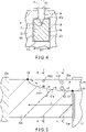
- FIG. 3 is a side view illustrating one end of the rotor in the axial direction with a partly broken section
- FIG. 4 is a cross-sectional view of the periphery of the rotor, taken along the line B-B of FIG. 3
- FIG. 5 is a schematic cross-sectional view of one bar end of the rotor bar.
- the swaging groove 60 is formed using, for example, a disc-shaped pressure roller R having a triangularly pointed outer periphery.
- the outer periphery of the pressure roller R is pressed against the upper surface 41a of the rotor bar 40 through the opening 52 of the rotor iron core 32, and the pressure roller R is moved along the opening 52 while rotating, and thereby, the swaging groove 60 is formed on the upper surface 41a of the rotor bar 40.
- the pressure roller R is moved axially from approximately the center of the longitudinal direction of the rotor bar 40 toward the first bar end 40a, and then, the pressure roller R is moved axially from approximately the center of the longitudinal direction of the rotor bar 40 toward the second bar end 40b.
- the swage groove 60 has a triangular cross-sectional shape, with the apex of the triangle forming the bottom edge 61 of the groove.
- the rotational center C2 of the pressure roller R moved to the first bar end 40a until the rotational center C2 of the pressure roller R coincides with the first end surface 32a.
- the first end swage groove 60a extends from the first end surface 32a to the extension end of the first bar end 40a by a length L1.
- the first end swage groove 60a extends in such a way that the depth gradually becomes shallower from the first end face 32a to the first groove end S2.
- the bottom edge 61a of the first end swage groove 60a extends from the bottom edge 61 of the swage groove 60 (base end S1) at the position of the first end face 32a to the first groove end S2 on the upper surface 41a, outward the radial direction in an inclined manner.
- the bottom edge 61a is curved and extends in an arc shape.
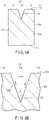
- FIG. 6A is a cross-sectional view of the rotor bar end, taken along line C-C of FIG. 3
- FIG. 6B is a cross-sectional view of the swage groove portion of the rotor bar end of FIG. 6A
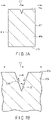
- FIG. 7A is a cross-sectional view of the rotor bar end, taken along line D-D of FIG. 3
- FIG. 7B is an enlarged cross-sectional view of the swage groove portion of the rotor bar end of FIG. 7A .
- the depth of the groove is approximately equal to the depth of the swage groove 60 at a position close to the rotor iron core 32 (at base end part), which is deep.
- the rotation of the rotor 16 generates an air flow CF that flows around the outer circumference of the first bar end 40a. This air flow CF generates a large vortex flow SW1 with high flow velocity in the first end swage groove 60a.
- the depth of the groove is shallower than the depth of the groove at the base end part. Therefore, the air flow CF generates a small vortex flow SW2 with low velocity in the first end swage groove 60a at the tip.
- the flow velocity and static pressure of the vortex flow generated in the first end swage groove 60a are different between the base side and the tip side. That is, at the base of the first end swage groove 60a, the vortex flow velocity is high and the static pressure PS1 is low, and conversely, at the tip of the first end swage groove 60a, the vortex flow velocity is low and the static pressure PS2 is high (PS2 > PS1).
- axial flow AF is generated in the first end swage groove 60a from the tip side, where the flow velocity is low and the static pressure PS2 is high, to the base side, where the flow velocity is high and the static pressure PS1 is low.
- This axial flow AF causes the air in the first end swage groove 60a to flow into the first end swage groove 60a from the outer circumference of the first groove end (end) S2 of the first end swage groove 60a, and the air flows from the rising start point (base) S1 side of the first end swage groove 60a to the outer peripheral side of the first bar end 40a.
- the air circulating in the first end swage groove 60a receives heat from the first bar end 40a, and rises in temperature, but does not become hot.
- the heat dissipation area of the rotor bar 40 increases, and the air temperature in the first end swage groove 60a does not become high, so the heat radiation from the first bar end 40a is accelerated. Therefore, the cooling performance of the rotor bar 40 and rotor iron core 32 is improved, and the temperature of the rotor can be lowered.
- the rotor bar 40 tends to warp to the outer circumference side.
- the warpage of the rotor bar 40 can be suppressed, and the need for post-processing such as cutting the tip of the rotor bar can be omitted.
- FIG. 8 is a schematic view illustrating the rotor bar and the swage groove.
- the swage groove may be provided only with one first bar end 40a, or on both bar ends.
- the second bar end 40b has a second end swage groove 60b that is continuous with the central swage groove 60.
- the pressure roller R is moved to the second bar end 40b side until the rotational center C2 of the pressure roller R is positioned slightly in front of the second end surface 32b of the rotor iron core 32.
- the second end swage groove 60b which is continuous with the swage groove 60, is formed on the second bar end 40b.
- the second end swage groove 60b extends from the location of the second end surface 32b toward the extension end of the second bar end 40b by a length L2.
- the axial length L2 is different from the axial length L1 of the first end swage groove 60a at the other end. That is, the length L2 is set to be shorter than the length L1 (L2 ⁇ L1).
- the second end swage groove 60b is gradually deepened from the position of the second end surface 32b to the second groove end.
- the bottom edge 61b of the second end swage groove 60b extends from the bottom edge 61 of the swage groove 60 at the second end surface 32b position to the second groove end on the top surface 41a, sloping outward in the radial direction of the rotor iron core 32.
- the bottom edge 61b is curved and extends in an arc shape.
- the axial flow AF causes air to flow into the first end swage groove 60a from the outer circumference of the rising end (first groove end) of the first swage groove 60a, and the air flows into the first end swage groove 60a from the outer circumference of the rising end (base) S1 side of the first end swage groove 60a flowing out from the outer circumference of the first bar end 40a.
- axial flow causes air to flow into the second end swage groove 60b from the outer side of the rising end (second groove end) of the second end swage groove 60b, and the air flows out from the outer circumference of the second bar end 40b from the rising start (base) side of the second end swage groove 60b.
- the swage groove near the first end face 32a of the rotor iron core 32 is deep, and a large vortex flow with high velocity is generated by the air flowing around the outer circumference of the first bar end 40a.
- the second end swage groove 60b which has a short axial length L2
- the swage groove near the second end face 32b of the rotor iron core 32 is shallow, and a small vortex flow with low velocity is generated in the second end swage groove 60b.
- axial flow is generated from the second end swage groove 60b, which has lower velocity and higher static pressure, to the opposite side, the first end swage groove 60a, which has higher velocity and lower static pressure.
- Air in the air gap, rotor iron core 32, and opening 52 flows through the swage groove 60 to the first bar end 40a side, and low temperature air flows from the second end swage groove 60b side into swage groove 60a.
- the air gap, rotor iron core 32, rotor iron core near opening 52, and rotor bar 40 will dissipate heat to lower temperature air, which will promote heat dissipation from the rotor 16, and reduce the temperature of the rotor 16.
- the rotor 16 of the rotary electric machine 10 of the present embodiment structured as above, by devising the swage groove 60 of the rotor bar 40, cooling of the rotor bar 40 and rotor iron core 32 can be accelerated, and the cooling performance can be improved. As a result, the rotor of the rotary electric machine with improved cooling performance and temperature reduction can be achieved.
- FIG. 9 is an enlarged cross-sectional view of a bar end portion of the rotor of the first modification.
- the bottom edge 61a of the first end swage groove 60a is not limited to being inclined on an arc, but may also extend linearly from the base S1 to the end S2, as in the figure.
- FIG. 10 is an enlarged cross-sectional view of a rotor bar portion of the rotor of the second modification.
- the cross-sectional shape of the rotor bar 40 is formed as a polygon in which the length of the upper surface (first side) 41a facing the opening 52 (circumferential width) is larger than the length of the opposite lower surface (rotational shaft side surface) (second side) 41b (circumferential width), for example, a trapezoid.
- the pair of sides 41c are inclined to taper toward the lower side 41b.
- the slot 50 of the rotor iron core 32 is formed in a cross-sectional shape with dimensions and shape corresponding to the rotor bar 40.
- the width W1 of the upper surface 41a is larger than the width W2 of the opening 52.
- the side 41c of the rotor bar 40 is in contact with the slope 51c of the slot 50, and the shoulder 43b of the rotor bar 40 is in contact with the shoulder 51b of the slot 50, reducing the contact thermal resistance between the rotor bar 40 and the rotor iron core 32.
- This makes it easier for the heat generated by the rotor bar 40 to be transmitted to the rotor iron core 32 and rotational shaft, which have a large heat capacity, and promotes heat dissipation from the rotor bar 40.
- the temperature of the rotor bar 40 and rotor iron core 32 can be reduced.
- Other effects similar to those of the aforementioned embodiment can also be obtained in the second modification.
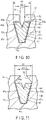
- FIG. 11 is an enlarged cross-sectional view of a rotor bar portion of the rotor of the third modification.
- the opening 52 of the rotor iron core 32 is formed so that it gradually becomes wider from the outer surface of the rotor iron core 32 to the upper end of the slot 50, that is, the upper surface 41a of the rotor bar 40.
- the width of the end of the slot 50 side of the opening 52 is substantially the same as the width W1 of the upper surface 41a.
- FIG. 12 is an enlarged cross-sectional view of a rotor bar portion of the rotor of the fourth modification.
- the opening 52 of the rotor iron core 32 is formed so that it gradually becomes wider from the outer surface of the rotor iron core 32 to the upper end of the slot 50, that is, the upper surface 41a of the rotor bar 40.
- the width of the end of the slot 50 side of the opening 52 is set to be smaller than the width W1 of the upper surface 41a.
- the width W1 of the upper surface 41a of the rotor bar 40 is larger than the width of the lower end of the opening 52, when the peripheral edge of the pressure roller R is pressed against the upper surface 41a of the rotor bar 40, the rotor bar 40 is pressed against the slope 51c of the slot 50, and at the same time, the shoulder 43b on the top surface 41a side of the rotor bar 40 is plastically deformed and pressed against the shoulder 51b of the slot 50, and is fixed to the rotor iron core 32.
- the side surface 41c of the rotor bar 40 is in contact with the slope 51b of the slot 50, and the shoulder 43b of the rotor bar 40 is in contact with the shoulder 51b of the slot 50.
- the ventilation resistance of the axial flow is reduced, and the ventilation flow rate is increased. This promotes the heat dissipation of the rotor bar 40 and rotor iron core 32, and improves the cooling performance of the rotor.
- FIG. 13 is an enlarged cross-sectional view of a rotor bar portion of the rotor of the fifth modification.
- the cross-sectional shape of the rotor bar 40 is not limited to a trapezoidal shape, but can be any other polygonal shape, for example, a pentagonal shape.
- the rotor bar 40 has an upper surface 41a facing the opening 52 and a lower surface 41b on the opposite side, and a swaging groove 60 is provided on the upper surface 41a.
- the rotor bar 40 has a width W1 that is largest approximately halfway between the upper and lower surfaces 41a and 41b.
- Each of the bent and sloping sides 41c is then pressed against the corresponding slope of the slot 50.
- the slot side end of the opening 52 gradually increases in circumferential width, and is approximately equal in width to the top surface of the rotor bar 40.
- the fifth modification structured as above can achieve the same effect as the third and fourth modifications described above.
Landscapes
- Engineering & Computer Science (AREA)
- Power Engineering (AREA)
- Manufacturing & Machinery (AREA)
- Iron Core Of Rotating Electric Machines (AREA)
- Induction Machinery (AREA)
- Windings For Motors And Generators (AREA)
- Motor Or Generator Cooling System (AREA)
- Permanent Magnet Type Synchronous Machine (AREA)
- Synchronous Machinery (AREA)
Abstract
Description
- Embodiments of the present application relate generally to a rotor of a rotary electric machine with rotor bars.
- As an example of rotary electric machines, an induction motor with a caged rotor structure is known. The caged rotor includes a rotor iron core, a plurality of rotor bars embedded in the rotor iron core, and an end ring connecting the rotor bars outside the rotor iron core. The rotor bar is inserted into a slot provided with the rotor iron core. Both ends of the rotor bar in the axial direction (bar ends) protrude outward from the both end surfaces of the rotor iron core. By subjecting a swage treatment to the rotor bars, that is, for example, by forming swage grooves in the rotor bars, the rotor bars are fixed to the slots of the rotor iron core. Normally, the swage groove is formed within a range of the rotor iron core, and is not formed in the bar end.
- In this condition, there are a plurality of bar ends are arranged in a circumferential manner between the end surface of the rotor iron core and the end ring, and as the rotor rotates, the bar ends function as a radial fan. That is, wind flows in a radial direction when the rotor rotates while wind close to the circumferential velocity of the rotor is generated in the outer peripheral side of the bar ends. When the electric machine is in operation, current flows in the rotor bar, and Joule heat occurs while the above-mentioned wind flow cools down the rotor bars and the rotor. In recent years, as the brazing technique progresses, the bar end length decreases. That results in decrease of radiation area of bar ends, and the cooling performance decreases. Therefore, increase of rotor temperature becomes greater.
- Patent Literature 1:
JP H11-18344 A - The embodiments of the present application aim to present a rotor of a rotary electric machine which can improve the cooling performance.
- According to an embodiment, a rotor of a rotary electric machine, comprises: a rotational shaft which is rotatable about a central axis; a rotator core coaxially fixed to the rotational shaft, the rotator core including a first end surface positioned on one end side in an axial direction and a second end surface positioned on the other end side in the axial direction, an outer peripheral surface which is coaxial with the central axis, a plurality of slots each formed to passing therethrough in the axial direction, opening on the first and second end surfaces, disposed at intervals in a circumferential direction of the outer peripheral surface, and a plurality of openings each formed in the outer peripheral surface, extending in the axial direction, and communicating with the slot; a plurality of rotor bars each inserted through the slot, and including a first bar end extending from the first end surface in the axial direction and a second bar end extending from the second end surface in the axial direction; a first annular end ring fixed to extending ends of the first bar ends; and a second annular end ring fixed to extending ends of the second bar ends. Each of the rotor bars includes a swage groove extending in the axial direction to be opposed to the opening, and a first end swage groove formed in the first bar end continuously to the swage groove, and the first end swage groove extends from the position of the first end surface toward the first end ring with being inclined to an outside in a radial direction of the rotator core.
-
-
FIG. 1 is a vertical cross-sectional view of a part of a rotary electric machine of an embodiment. -
FIG. 2 is a cross-sectional view of the rotor of the rotary electric machine, taken along line A-A ofFIG. 1 , depicted in a partially enlarged manner. -
FIG. 3 is a side surface view of one end of the rotor in an axial direction, depicted in a partially broken manner. -
FIG. 4 is a cross-sectional view of the outer peripheral part of the rotor, taken along line B-B ofFIG. 3 . -
FIG. 5 is a schematic cross-sectional view of one bar end of a rotor bar. -
FIG. 6A is a cross-sectional view of a rotor bar end, taken along line C-C ofFIG. 3 . -
FIG. 6B is a cross-sectional view of the rotor bar end, in which a swage groove part is depicted in an enlarged manner. -
FIG. 7A is a cross-sectional view of the rotor bar end, taken along line D-D ofFIG. 3 . -
FIG. 7B is a cross-sectional view of the rotor bar end, in which the swage groove part is depicted in an enlarged manner. -
FIG. 8 is a schematic view of the rotor bar and the swage groove. -
FIG. 9 is a cross-sectional view of a rotor of a first modification, in which a bar end part is depicted in an enlarged manner. -
FIG. 10 is a cross-sectional view of a rotor of a second modification. -
FIG. 11 is a cross-sectional view of a rotor of a third modification. -
FIG. 12 is a cross-sectional view of a rotor of a fourth modification. -
FIG. 13 is a cross-sectional view of a rotor of a fifth modification. - Modes for Carrying Out the Invention Embodiments of the present invention will be described below with reference to the accompanying drawings. Elements like or similar to those disclosed in the above embodiment are denoted by similar reference numbers and are not described in detail here. Each figure is a schematic diagram illustrating the embodiments, and should be used to understand them while the shape, size, and ratio of the figures may differ from the actual implementation of the invention. Such differences are a matter of design to be arbitrarily made with reference to the following description and publically-known arts.
-
FIG. 1 is a vertical cross-sectional view of a rotary electric machine of an embodiment, which illustrates the rotary electric machine divided half along the central axis thereof. - As in
FIG. 1 , a rotaryelectric machine 10 is configured as, for example, an inner rotor type rotary electric machine. The rotaryelectric machine 10 includes an internally sealedcase 12,stator 14 arranged inside thecase 12, and cage-type rotor 16. - The
case 12 includes a substantiallycylindrical frame 18, disk-shapedfirst bracket 19 attached to one end of theframe 18 in the axial direction in a manner to close the end, and disk-shapedsecond bracket 20 attached to the other axial end of theframe 18 in a manner to close the other end. To the center of thefirst bracket 19, a first bearinghousing 22a, which incorporates a bearing B1, is bolted. To the center of thesecond bracket 20, a second bearinghousing 22b, which incorporates a bearing B2, is bolted. The bearings B1 and B2 are aligned along the central axis C1 of the rotaryelectric machine 10. - The
stator 14 has a cylindricalstator iron core 24 and a stator coils wound around thestator iron core 24. Thestator iron core 24 is supported by theframe 18 with its outer peripheral surface engaged with the inner peripheral surface of theframe 18, and is arranged coaxially with the central axis C1. A pair of annulariron core holders stator iron core 24. Thestator iron core 24 includes a number of laminated annular metal plates formed of magnetic material, for example, silicon steel plate. A plurality of slots, each extending in the axial direction, are formed in the inner circumference of thestator iron core 24. Thestator coil 28 is embedded in the slots and attached to thestator iron core 24. The coil ends 28e of thestator coil 28 extend in the axial direction from both ends of thestator iron core 24. - The
rotor 16 includes arotational shaft 30, rotor core (rotor iron core) 32, a plurality ofrotor bars 40 embedded in therotor iron core 32, and a pair ofend rings rotor bars 40 at both ends. Therotational shaft 30 is disposed in thecase 12 coaxially with the central axis C1, and is rotatably supported by the bearings B1 and B2 at the one end and the other end thereof in the axial direction, respectively. Adrive side end 30a of therotational shaft 30 extends outside the machine. A coupling for connecting a drive gear device, etc., is attached to thedrive side end 30a. - The
rotor iron core 32 includes a number of annular metal plates made of magnetic material, for example, silicon steel plate, laminated together to form a substantially cylindrical shape. Therotor iron core 32 is mounted in the approximate center of therotational shaft 30 in the axial direction, and is located inside thestator iron core 24, coaxially with the central axis C1. The outer periphery of therotor iron core 32 faces the inner periphery of thestator iron core 24 with a gap G. The axial length of therotor iron core 32 is substantially equal to the axial length of thestator iron core 24. Furthermore, therotor iron core 32 has afirst end face 32a located at one end in the axial direction and asecond end face 32b located at the other end in the axial direction. Thefirst end face 32a and thesecond end face 32b extend in a manner to be substantially perpendicular to the central axis C1. - The
rotor iron core 32 is supported on therotational shaft 30 by a pair of iron core supports 34a, 34b such that it is sandwiched from both ends in the axial direction. The ironcore support plates rotor iron core 32. -
FIG. 2 is a cross-sectional view of the rotor, taken along line A-A inFIG. 1 , andFIG. 4 is an enlarged cross-sectional view of the rotor bar portion of the rotor. - As shown in
FIGS. 1 and2 , a plurality ofventilation ducts 44 are formed in therotor iron core 32 and theiron core pushers ventilation ducts 44 are provided at regular intervals in the circumferential direction around the central axis C1. - A plurality of slots (grooves) 50 are formed on the outer periphery of the
rotor iron core 32, each extending in the axial direction and arranged at regular intervals in the circumferential direction. Eachslot 50 extends through therotor iron core 32 in the axial direction, and opens in thefirst end surface 32 and thesecond end surface 32b. Eachslot 50 also opens to the outer circumference of therotor iron core 32 through anopening 52 having a circumferential width W2. Theopening 52 extends over the entire axial length of therotor iron core 32. The cross-sectional shape of theslot 50 is, for example, a rectangular shape. The circumferential width W1 of theslot 50 is set to be larger than the circumferential width W2 of theopening 52. - The
rotor bar 40 is inserted into eachslot 50, and extends in the axial direction of therotor iron core 32. The cross-sectional shape of therotor bar 40 is, for example, formed in a rectangular shape with a size (dimension) corresponding to the cross-sectional shape of theslot 50. As shown inFIGS. 2 and4 , therotor bar 40 has a pair of short side surfaces (upper surface 41a andlower surface 41b) and a pair of long side surfaces (a pair of side surfaces 41c) opposed to each other. Therotor bar 40 is disposed in theslot 50 such that thetop surface 41a faces the outer peripheral surface of therotor iron core 32, that is, thetop surface 41a is opposed to theopening 52. - As in
FIG. 1 , onelongitudinal end 40a of the rotor bar 40 (first bar end) extends outward from thefirst end surface 32a of therotor iron core 32. The otherlongitudinal end 40b of the rotor bar 40 (second bar end) extends outward from thesecond end face 32b of therotor iron core 32. The extension length of thefirst bar end 40a and the extension length of thesecond bar end 40b are set to be substantially equal. - As an example of the swaging process, a
swaging groove 60 is formed on thetop surface 41a of therotor bar 40, and thereby, therotor bar 40 is caulked and fixed in theslot 50 of therotor iron core 32. That is, a pair of side surfaces 41c of therotor bar 40 are pressed against therotor iron core 32 to be fixed to therotor iron core 32. - A
circular end ring 42a is fixed to the extension end of thefirst bar end 40a. Theend ring 42a is arranged coaxially with the central axis C1, and connects the bar ends 40a to each other. Acircular end ring 42b is fixed to the extension end of thesecond bar end 40b. Theend ring 42b is disposed coaxially with the central axis C1, and connects the bar ends 40 to each other. Therotor bar 40 and the end rings 42a, 42b are formed of, for example, conductive metal materials such as aluminum and copper. - The rotor bars 40 and a pair of end rings 42a and 42b form a cage rotor of the induction motor. When the
stator coil 28 is energized, therotor iron core 32 is induced to rotate, and the rotating axis 11 is rotated together with therotor iron core 32. - Next, the
swaging groove 60 will be explained in detail. -
FIG. 3 is a side view illustrating one end of the rotor in the axial direction with a partly broken section, andFIG. 4 is a cross-sectional view of the periphery of the rotor, taken along the line B-B ofFIG. 3 , andFIG. 5 is a schematic cross-sectional view of one bar end of the rotor bar. - As in
FIGS. 3 and4 , theswaging groove 60 is formed using, for example, a disc-shaped pressure roller R having a triangularly pointed outer periphery. The outer periphery of the pressure roller R is pressed against theupper surface 41a of therotor bar 40 through theopening 52 of therotor iron core 32, and the pressure roller R is moved along theopening 52 while rotating, and thereby, theswaging groove 60 is formed on theupper surface 41a of therotor bar 40. In this process, the pressure roller R is moved axially from approximately the center of the longitudinal direction of therotor bar 40 toward thefirst bar end 40a, and then, the pressure roller R is moved axially from approximately the center of the longitudinal direction of therotor bar 40 toward thesecond bar end 40b. This creates aswage groove 60 of constant depth in therotor bar 40 over the entire length of the area located in theslot 50 of therotor iron core 32. Theswage groove 60 has a triangular cross-sectional shape, with the apex of the triangle forming thebottom edge 61 of the groove. - As shown in
FIG. 3 , in the processing of theswage groove 60, the rotational center C2 of the pressure roller R moved to thefirst bar end 40a until the rotational center C2 of the pressure roller R coincides with thefirst end surface 32a. This causes the firstend swage groove 60a, which is continuous with theswage groove 60, to be formed on thefirst bar end 40a. As shown inFIGS. 3 and5 , the firstend swage groove 60a extends from thefirst end surface 32a to the extension end of thefirst bar end 40a by a length L1. The firstend swage groove 60a extends in such a way that the depth gradually becomes shallower from thefirst end face 32a to the first groove end S2. That is, thebottom edge 61a of the firstend swage groove 60a extends from thebottom edge 61 of the swage groove 60 (base end S1) at the position of thefirst end face 32a to the first groove end S2 on theupper surface 41a, outward the radial direction in an inclined manner. In this embodiment, thebottom edge 61a is curved and extends in an arc shape. -
FIG. 6A is a cross-sectional view of the rotor bar end, taken along line C-C ofFIG. 3 ,FIG. 6B is a cross-sectional view of the swage groove portion of the rotor bar end ofFIG. 6A .FIG. 7A is a cross-sectional view of the rotor bar end, taken along line D-D ofFIG. 3 , andFIG. 7B is an enlarged cross-sectional view of the swage groove portion of the rotor bar end ofFIG. 7A . - As in
FIGS. 5 ,6A, and 6B , in the firstend swage groove 60a on thefirst bar end 40a, the depth of the groove is approximately equal to the depth of theswage groove 60 at a position close to the rotor iron core 32 (at base end part), which is deep. The rotation of therotor 16 generates an air flow CF that flows around the outer circumference of thefirst bar end 40a. This air flow CF generates a large vortex flow SW1 with high flow velocity in the firstend swage groove 60a. - On the other hand, as shown in
FIGS. 7A and 7B , in the firstend swage groove 60a, at a position distant from the rotor iron core 32 (at tip part), the depth of the groove is shallower than the depth of the groove at the base end part. Therefore, the air flow CF generates a small vortex flow SW2 with low velocity in the firstend swage groove 60a at the tip. - As shown in
FIG. 5 , the flow velocity and static pressure of the vortex flow generated in the firstend swage groove 60a are different between the base side and the tip side. That is, at the base of the firstend swage groove 60a, the vortex flow velocity is high and the static pressure PS1 is low, and conversely, at the tip of the firstend swage groove 60a, the vortex flow velocity is low and the static pressure PS2 is high (PS2 > PS1). Thus, axial flow AF is generated in the firstend swage groove 60a from the tip side, where the flow velocity is low and the static pressure PS2 is high, to the base side, where the flow velocity is high and the static pressure PS1 is low. This axial flow AF causes the air in the firstend swage groove 60a to flow into the firstend swage groove 60a from the outer circumference of the first groove end (end) S2 of the firstend swage groove 60a, and the air flows from the rising start point (base) S1 side of the firstend swage groove 60a to the outer peripheral side of thefirst bar end 40a. The air circulating in the firstend swage groove 60a receives heat from thefirst bar end 40a, and rises in temperature, but does not become hot. With theswage groove 60 and the firstend swage groove 60a structured as above, the heat dissipation area of therotor bar 40 increases, and the air temperature in the firstend swage groove 60a does not become high, so the heat radiation from thefirst bar end 40a is accelerated. Therefore, the cooling performance of therotor bar 40 androtor iron core 32 is improved, and the temperature of the rotor can be lowered. - As described above, when the pressure roller R for swaging grooves is pressed and rotated from the center side of the
rotor iron core 32 toward thefirst end face 32, therotor bar 40 tends to warp to the outer circumference side. However, by pressing therotor bar 40 while rotating the pressure roller R until the rotational center C2 of the pressure roller R coincides with thefirst end surface 32a of therotor iron core 32, the warpage of therotor bar 40 can be suppressed, and the need for post-processing such as cutting the tip of the rotor bar can be omitted. -
FIG. 8 is a schematic view illustrating the rotor bar and the swage groove. - The swage groove may be provided only with one
first bar end 40a, or on both bar ends. As inFIG. 8 , according to the present embodiment, thesecond bar end 40b has a secondend swage groove 60b that is continuous with thecentral swage groove 60. By continuously rotating the aforementioned pressure roller R pressed against theupper surface 41a of therotor bar 40 from the axial center of therotor iron core 32 to thesecond bar end 40b in the axial direction, theswage groove 60 is formed on theupper surface 41a of therotor bar 40. In the processing of theswage groove 60, the pressure roller R is moved to thesecond bar end 40b side until the rotational center C2 of the pressure roller R is positioned slightly in front of thesecond end surface 32b of therotor iron core 32. As a result, the secondend swage groove 60b, which is continuous with theswage groove 60, is formed on thesecond bar end 40b. - The second
end swage groove 60b extends from the location of thesecond end surface 32b toward the extension end of thesecond bar end 40b by a length L2. The axial length L2 is different from the axial length L1 of the firstend swage groove 60a at the other end. That is,, the length L2 is set to be shorter than the length L1 (L2<L1). The secondend swage groove 60b is gradually deepened from the position of thesecond end surface 32b to the second groove end. That is, thebottom edge 61b of the secondend swage groove 60b extends from thebottom edge 61 of theswage groove 60 at thesecond end surface 32b position to the second groove end on thetop surface 41a, sloping outward in the radial direction of therotor iron core 32. In the present embodiment, thebottom edge 61b is curved and extends in an arc shape. - As the
rotor 16 rotates, as shown by the arrow inFIG. 8 , in the firstend swage groove 60a, as described above, the axial flow AF causes air to flow into the firstend swage groove 60a from the outer circumference of the rising end (first groove end) of thefirst swage groove 60a, and the air flows into the firstend swage groove 60a from the outer circumference of the rising end (base) S1 side of the firstend swage groove 60a flowing out from the outer circumference of thefirst bar end 40a. - In the second
end swage groove 60b, axial flow causes air to flow into the secondend swage groove 60b from the outer side of the rising end (second groove end) of the secondend swage groove 60b, and the air flows out from the outer circumference of thesecond bar end 40b from the rising start (base) side of the secondend swage groove 60b. - In the first
end swage groove 60a, which has a long axial length L1, the swage groove near thefirst end face 32a of therotor iron core 32 is deep, and a large vortex flow with high velocity is generated by the air flowing around the outer circumference of thefirst bar end 40a. On the other hand, in the secondend swage groove 60b, which has a short axial length L2, the swage groove near thesecond end face 32b of therotor iron core 32 is shallow, and a small vortex flow with low velocity is generated in the secondend swage groove 60b. Furthermore, in theswage groove 60 formed in the center of therotor bar 40, axial flow is generated from the secondend swage groove 60b, which has lower velocity and higher static pressure, to the opposite side, the firstend swage groove 60a, which has higher velocity and lower static pressure. Air in the air gap,rotor iron core 32, and opening 52 flows through theswage groove 60 to thefirst bar end 40a side, and low temperature air flows from the secondend swage groove 60b side intoswage groove 60a. - Therefore, the air gap,
rotor iron core 32, rotor iron core near opening 52, androtor bar 40 will dissipate heat to lower temperature air, which will promote heat dissipation from therotor 16, and reduce the temperature of therotor 16. - According to the
rotor 16 of the rotaryelectric machine 10 of the present embodiment structured as above, by devising theswage groove 60 of therotor bar 40, cooling of therotor bar 40 androtor iron core 32 can be accelerated, and the cooling performance can be improved. As a result, the rotor of the rotary electric machine with improved cooling performance and temperature reduction can be achieved. - Next, a rotor of a rotary electric machine according to a modification of the present invention will be described. In the modifications described below, the same reference numbers are attached to the same parts as in the aforementioned embodiment to omit or simplify the detailed description thereof, and the detailed description will focus on the parts that differ from the embodiment.
-
FIG. 9 is an enlarged cross-sectional view of a bar end portion of the rotor of the first modification. - The
bottom edge 61a of the firstend swage groove 60a is not limited to being inclined on an arc, but may also extend linearly from the base S1 to the end S2, as in the figure. - In the first
end swage groove 60a structured as above, the same effect as in the embodiment described above can be obtained. -
FIG. 10 is an enlarged cross-sectional view of a rotor bar portion of the rotor of the second modification. - As in the figure, according to the second modification, the cross-sectional shape of the
rotor bar 40 is formed as a polygon in which the length of the upper surface (first side) 41a facing the opening 52 (circumferential width) is larger than the length of the opposite lower surface (rotational shaft side surface) (second side) 41b (circumferential width), for example, a trapezoid. The pair ofsides 41c are inclined to taper toward thelower side 41b. Theslot 50 of therotor iron core 32 is formed in a cross-sectional shape with dimensions and shape corresponding to therotor bar 40. The width W1 of theupper surface 41a is larger than the width W2 of theopening 52. - When the periphery of the pressure roller R for swage groove processing is pressed against the
upper surface 41a of therotor bar 40 through theopening 52, therotor bar 40 is pressed against theslope 51c of the slot, and at the same time, theshoulders 43b on theupper side 41a of therotor bar 40 are plastically deformed, pressed against theshoulder 51b of theslot 50, and fixed to therotor iron core 32. From one end of therotor iron core 32 to the other end in the axial direction, theside 41c of therotor bar 40 is in contact with theslope 51c of theslot 50, and theshoulder 43b of therotor bar 40 is in contact with theshoulder 51b of theslot 50, reducing the contact thermal resistance between therotor bar 40 and therotor iron core 32. This makes it easier for the heat generated by therotor bar 40 to be transmitted to therotor iron core 32 and rotational shaft, which have a large heat capacity, and promotes heat dissipation from therotor bar 40. Thus, the temperature of therotor bar 40 androtor iron core 32 can be reduced. Other effects similar to those of the aforementioned embodiment can also be obtained in the second modification. -
FIG. 11 is an enlarged cross-sectional view of a rotor bar portion of the rotor of the third modification. - As in the figure, according to the third modification, the
opening 52 of therotor iron core 32 is formed so that it gradually becomes wider from the outer surface of therotor iron core 32 to the upper end of theslot 50, that is, theupper surface 41a of therotor bar 40. The width of the end of theslot 50 side of theopening 52 is substantially the same as the width W1 of theupper surface 41a. By increasing the width of theopening 52 in this way, the cross-sectional area of theopening 52 is made larger. - In a rotary electric machine with an axially ventilated rotor or a rotor with a skewed rotor iron core, if there is a difference in pressure on both sides of the
rotor iron core 32 in the axial direction, the air in the machine will flow axially through theopening 52. In this case, by setting the cross-sectional area of theopening 52 to be large as described above, the ventilation resistance is reduced and the flow rate is increased. This promotes heat dissipation from therotor iron core 32 androtor bar 40, making it possible to reduce the temperature of the rotor. -
FIG. 12 is an enlarged cross-sectional view of a rotor bar portion of the rotor of the fourth modification. - As in the figure, according to the third modification, the
opening 52 of therotor iron core 32 is formed so that it gradually becomes wider from the outer surface of therotor iron core 32 to the upper end of theslot 50, that is, theupper surface 41a of therotor bar 40. The width of the end of theslot 50 side of theopening 52 is set to be smaller than the width W1 of theupper surface 41a. By increasing the width of theopening 52 in this way, the cross-sectional area of theopening 52 is made larger. - Since the width W1 of the
upper surface 41a of therotor bar 40 is larger than the width of the lower end of theopening 52, when the peripheral edge of the pressure roller R is pressed against theupper surface 41a of therotor bar 40, therotor bar 40 is pressed against theslope 51c of theslot 50, and at the same time, theshoulder 43b on thetop surface 41a side of therotor bar 40 is plastically deformed and pressed against theshoulder 51b of theslot 50, and is fixed to therotor iron core 32. From one end to the other in the axial direction of therotor iron core 32, theside surface 41c of therotor bar 40 is in contact with theslope 51b of theslot 50, and theshoulder 43b of therotor bar 40 is in contact with theshoulder 51b of theslot 50. This reduces the contact thermal resistance between therotor bar 40 and therotor iron core 32. In addition, by increasing the width of theopening 52, the ventilation resistance of the axial flow is reduced, and the ventilation flow rate is increased. This promotes the heat dissipation of therotor bar 40 androtor iron core 32, and improves the cooling performance of the rotor. -
FIG. 13 is an enlarged cross-sectional view of a rotor bar portion of the rotor of the fifth modification. - As in the figure, the cross-sectional shape of the
rotor bar 40 is not limited to a trapezoidal shape, but can be any other polygonal shape, for example, a pentagonal shape. Therotor bar 40 has anupper surface 41a facing theopening 52 and alower surface 41b on the opposite side, and aswaging groove 60 is provided on theupper surface 41a. Therotor bar 40 has a width W1 that is largest approximately halfway between the upper andlower surfaces sides 41c is then pressed against the corresponding slope of theslot 50. The slot side end of theopening 52 gradually increases in circumferential width, and is approximately equal in width to the top surface of therotor bar 40. - The fifth modification structured as above can achieve the same effect as the third and fourth modifications described above.
- While certain embodiments have been described, these embodiments have been presented by way of example only, and are not intended to limit the scope of the inventions. Indeed, the novel embodiments described herein may be embodied in a variety of other forms; furthermore, various omissions, substitutions and changes in the form of the embodiments described herein may be made without departing from the spirit of the inventions. The accompanying claims and their equivalents are intended to cover such forms or modifications as would fall within the scope and spirit of the inventions.
Claims (8)
- A rotor of a rotary electric machine, comprising:a rotational shaft which is rotatable about a central axis;a rotator core coaxially fixed to the rotational shaft, the rotator core including a first end surface positioned on one end side in an axial direction and a second end surface positioned on the other end side in the axial direction, an outer peripheral surface which is coaxial with the central axis, a plurality of slots each formed to passing therethrough in the axial direction, opening on the first and second end surfaces, disposed at intervals in a circumferential direction of the outer peripheral surface, and a plurality of openings each formed in the outer peripheral surface, extending in the axial direction, and communicating with the slot;a plurality of rotor bars each inserted through the slot, and including a first bar end extending from the first end surface in the axial direction and a second bar end extending from the second end surface in the axial direction;a first annular end ring fixed to extending ends of the first bar ends; anda second annular end ring fixed to extending ends of the second bar ends, whereineach of the rotor bars includes a swage groove extending in the axial direction to be opposed to the opening, and a first end swage groove formed in the first bar end continuously to the swage groove, and the first end swage groove extends from the position of the first end surface toward the first end ring with being inclined to an outside in a radial direction of the rotator core.
- The rotor of rotary electric machine of claim 1, wherein each of the rotor bars includes a second end swage groove formed in the second bar end continuously to the swage groove, and the second end swage groove extends from the position of the second end surface toward the second end ring with being inclined to the outside in the radial direction of the rotator core.
- The rotor of rotary electric machine of claim 2, wherein, given a length of the first end swage groove in the axial direction from the first end surface to an groove end is a first length and a length of the second end swage groove in the axial direction from the second end surface to a groove end is a second length, the first length and the second length are different from each other.
- The rotor of rotary electric machine of any one of claims 1 to 3, wherein the rotor bar has a polygonal cross-sectional shape in which a first side opposed to the opening is greater than a second side opposed to the first side.
- The rotor of rotary electric machine of any one of claims 1 to 3, wherein the opening has a width in the circumferential direction, and the width in the circumferential direction gradually increases from the outer peripheral surface side toward the slot side.
- The rotor of rotary electric machine of any one of claims 1 to 3, wherein the rotor bar includes a first surface having a first width in the circumferential direction and opposed to the opening, and a width in the circumferential direction in an end of the opening on the slot side is smaller than the first width.
- The rotor of rotary electric machine of any one of claims 1 to 3, wherein the first end swage groove extends from the position of the first end surface to an extending end of the groove in a curved manner.
- The rotor of rotary electric machine of any one of claims 1 to 3, wherein the first end swage groove extends from the position of the first end surface to an extending end of the groove in a linear manner.
Applications Claiming Priority (2)
| Application Number | Priority Date | Filing Date | Title |
|---|---|---|---|
| JP2019185091A JP6848029B1 (en) | 2019-10-08 | 2019-10-08 | Rotor of rotating electric machine |
| PCT/JP2020/037887 WO2021070823A1 (en) | 2019-10-08 | 2020-10-06 | Rotor for rotating electrical machine |
Publications (2)
| Publication Number | Publication Date |
|---|---|
| EP4044412A1 true EP4044412A1 (en) | 2022-08-17 |
| EP4044412A4 EP4044412A4 (en) | 2023-10-25 |
Family
ID=74879267
Family Applications (1)
| Application Number | Title | Priority Date | Filing Date |
|---|---|---|---|
| EP20873562.1A Pending EP4044412A4 (en) | 2019-10-08 | 2020-10-06 | ROTOR OF ROTATING ELECTRIC MACHINE |
Country Status (5)
| Country | Link |
|---|---|
| EP (1) | EP4044412A4 (en) |
| JP (1) | JP6848029B1 (en) |
| CN (1) | CN114586260B (en) |
| TW (1) | TWI778425B (en) |
| WO (1) | WO2021070823A1 (en) |
Families Citing this family (1)
| Publication number | Priority date | Publication date | Assignee | Title |
|---|---|---|---|---|
| KR20250003872A (en) * | 2022-07-29 | 2025-01-07 | 가부시키가이샤 히다치 인더스트리얼 프로덕츠 | Rotating electric machine and method for forming slits in rotor slots |
Family Cites Families (15)
| Publication number | Priority date | Publication date | Assignee | Title |
|---|---|---|---|---|
| JPH03107701A (en) * | 1989-09-21 | 1991-05-08 | Mitsubishi Electric Corp | Simple measuring instrument |
| JPH06284608A (en) * | 1993-03-29 | 1994-10-07 | Mitsubishi Electric Corp | Ac rotating machine |
| JP3266768B2 (en) * | 1995-08-28 | 2002-03-18 | 三菱電機株式会社 | Cage induction motor rotor and cage induction motor |
| JPH09233784A (en) * | 1996-02-28 | 1997-09-05 | Toyo Electric Mfg Co Ltd | Rotor of basket type induction motor |
| JP2001178080A (en) * | 1999-12-20 | 2001-06-29 | Meidensha Corp | Cooling structure for rotor winding |
| JP3650351B2 (en) * | 2001-09-07 | 2005-05-18 | 三菱電機株式会社 | Cage type induction motor rotor and cage type induction motor |
| GB0323232D0 (en) * | 2003-10-03 | 2003-11-05 | Rolls Royce Plc | Electrical machine |
| JP5664936B2 (en) * | 2012-11-22 | 2015-02-04 | 株式会社安川電機 | Rotating electric machine and rotor |
| JP5720715B2 (en) * | 2013-03-29 | 2015-05-20 | 株式会社デンソー | Rotating electric machine |
| JP6383677B2 (en) * | 2015-02-09 | 2018-08-29 | 東芝三菱電機産業システム株式会社 | Rotor of squirrel-cage electric machine and method of manufacturing rotor |
| JP6509615B2 (en) * | 2015-04-10 | 2019-05-08 | 株式会社日立製作所 | Induction machine, and induction machine drive system and railway vehicle using the same |
| CN105356687B (en) * | 2015-11-11 | 2017-10-03 | 成都中车电机有限公司 | It is a kind of to the undamaged sliver method for dismounting of traction motor cage rotor punching |
| JP6665770B2 (en) * | 2016-12-20 | 2020-03-13 | 株式会社デンソー | Rotor of rotating electric machine and rotating electric machine |
| WO2019026673A1 (en) * | 2017-08-01 | 2019-02-07 | 三菱電機株式会社 | Rotation drive device, method for mounting rotation drive device, axial flow blower, method for mounting axial flow blower, and lasing device |
| JP2019146387A (en) * | 2018-02-21 | 2019-08-29 | 本田技研工業株式会社 | Cooling structure of rotary electric machine and rotary electric machine |
-
2019
- 2019-10-08 JP JP2019185091A patent/JP6848029B1/en not_active Expired - Fee Related
-
2020
- 2020-10-06 CN CN202080070842.8A patent/CN114586260B/en not_active Expired - Fee Related
- 2020-10-06 WO PCT/JP2020/037887 patent/WO2021070823A1/en not_active Ceased
- 2020-10-06 EP EP20873562.1A patent/EP4044412A4/en active Pending
- 2020-10-08 TW TW109134898A patent/TWI778425B/en not_active IP Right Cessation
Also Published As
| Publication number | Publication date |
|---|---|
| CN114586260B (en) | 2024-01-16 |
| TWI778425B (en) | 2022-09-21 |
| WO2021070823A1 (en) | 2021-04-15 |
| CN114586260A (en) | 2022-06-03 |
| JP6848029B1 (en) | 2021-03-24 |
| JP2021061701A (en) | 2021-04-15 |
| TW202121798A (en) | 2021-06-01 |
| EP4044412A4 (en) | 2023-10-25 |
Similar Documents
| Publication | Publication Date | Title |
|---|---|---|
| JP6367875B2 (en) | Rotor structure of rotating electrical machine | |
| KR102016863B1 (en) | Rotary electric appliance cooling structure | |
| EP2795776B1 (en) | Rotor for a line start permanent magnet machine | |
| EP2973949B1 (en) | Rotor for rotary electric machine and rotary electric machine | |
| JP2020127288A (en) | Rotor iron core, rotor, rotary electric machine, blower, rotor iron core manufacturing method, and rotor core manufacturing method | |
| JP6425065B2 (en) | Electric rotating machine | |
| EP2808571B1 (en) | Electro-magnetic bearing assembly with inner ventilation to cool the bearing | |
| KR20180081705A (en) | A rotary electric machine comprising a rotor and a stator for passing fluid therethrough | |
| CN105827081B (en) | Optimized for high power motor rotor | |
| CN114586260B (en) | rotor of rotating electrical machine | |
| CN110707888B (en) | Rotating electric machine and rotor | |
| CA3071259C (en) | Stators comprising air flow slots | |
| CN112655141B (en) | Squirrel Rotors and Rotating Electric Machines | |
| EP2066007A2 (en) | Rotary electric machine | |
| JP6473128B2 (en) | Synchronous rotating electrical machine and field winding end holding structure | |
| US10550851B2 (en) | Fan having an impeller including a resin portion and a metal plate | |
| KR102524404B1 (en) | electric induction machine | |
| JP2016220404A (en) | Squirrel-cage induction motor, squirrel-cage induction motor rotor and rotor manufacturing method | |
| US12438408B2 (en) | Induction motor | |
| JP7273744B2 (en) | magnetic gear device | |
| KR101834338B1 (en) | Induction Motor | |
| JP7609922B2 (en) | Rotating Electric Machine | |
| KR102796751B1 (en) | Rotor and moter having the same | |
| JP5404525B2 (en) | Rotating electric machine | |
| WO2015171485A1 (en) | Asymmetric rotor for a line start permanent magnet machine |
Legal Events
| Date | Code | Title | Description |
|---|---|---|---|
| STAA | Information on the status of an ep patent application or granted ep patent |
Free format text: STATUS: THE INTERNATIONAL PUBLICATION HAS BEEN MADE |
|
| PUAI | Public reference made under article 153(3) epc to a published international application that has entered the european phase |
Free format text: ORIGINAL CODE: 0009012 |
|
| STAA | Information on the status of an ep patent application or granted ep patent |
Free format text: STATUS: REQUEST FOR EXAMINATION WAS MADE |
|
| 17P | Request for examination filed |
Effective date: 20220331 |
|
| AK | Designated contracting states |
Kind code of ref document: A1 Designated state(s): AL AT BE BG CH CY CZ DE DK EE ES FI FR GB GR HR HU IE IS IT LI LT LU LV MC MK MT NL NO PL PT RO RS SE SI SK SM TR |
|
| DAV | Request for validation of the european patent (deleted) | ||
| DAX | Request for extension of the european patent (deleted) | ||
| A4 | Supplementary search report drawn up and despatched |
Effective date: 20230922 |
|
| RIC1 | Information provided on ipc code assigned before grant |
Ipc: H02K 1/26 20060101ALI20230918BHEP Ipc: H02K 15/00 20060101ALI20230918BHEP Ipc: H02K 9/08 20060101ALI20230918BHEP Ipc: H02K 9/02 20060101ALI20230918BHEP Ipc: H02K 3/24 20060101ALI20230918BHEP Ipc: H02K 17/16 20060101AFI20230918BHEP |
|
| RAP1 | Party data changed (applicant data changed or rights of an application transferred) |
Owner name: KABUSHIKI KAISHA TOSHIBA |
|
| GRAP | Despatch of communication of intention to grant a patent |
Free format text: ORIGINAL CODE: EPIDOSNIGR1 |
|
| STAA | Information on the status of an ep patent application or granted ep patent |
Free format text: STATUS: GRANT OF PATENT IS INTENDED |
|
| INTG | Intention to grant announced |
Effective date: 20260414 |