EP4044344A1 - Battery packaging container - Google Patents
Battery packaging container Download PDFInfo
- Publication number
- EP4044344A1 EP4044344A1 EP22154527.0A EP22154527A EP4044344A1 EP 4044344 A1 EP4044344 A1 EP 4044344A1 EP 22154527 A EP22154527 A EP 22154527A EP 4044344 A1 EP4044344 A1 EP 4044344A1
- Authority
- EP
- European Patent Office
- Prior art keywords
- wall
- lateral
- edge
- bottom wall
- packaging container
- Prior art date
- Legal status (The legal status is an assumption and is not a legal conclusion. Google has not performed a legal analysis and makes no representation as to the accuracy of the status listed.)
- Granted
Links
Images




Classifications
-
- H—ELECTRICITY
- H01—ELECTRIC ELEMENTS
- H01M—PROCESSES OR MEANS, e.g. BATTERIES, FOR THE DIRECT CONVERSION OF CHEMICAL ENERGY INTO ELECTRICAL ENERGY
- H01M50/00—Constructional details or processes of manufacture of the non-active parts of electrochemical cells other than fuel cells, e.g. hybrid cells
- H01M50/20—Mountings; Secondary casings or frames; Racks, modules or packs; Suspension devices; Shock absorbers; Transport or carrying devices; Holders
- H01M50/202—Casings or frames around the primary casing of a single cell or a single battery
-
- B—PERFORMING OPERATIONS; TRANSPORTING
- B65—CONVEYING; PACKING; STORING; HANDLING THIN OR FILAMENTARY MATERIAL
- B65D—CONTAINERS FOR STORAGE OR TRANSPORT OF ARTICLES OR MATERIALS, e.g. BAGS, BARRELS, BOTTLES, BOXES, CANS, CARTONS, CRATES, DRUMS, JARS, TANKS, HOPPERS, FORWARDING CONTAINERS; ACCESSORIES, CLOSURES, OR FITTINGS THEREFOR; PACKAGING ELEMENTS; PACKAGES
- B65D5/00—Rigid or semi-rigid containers of polygonal cross-section, e.g. boxes, cartons or trays, formed by folding or erecting one or more blanks made of paper
- B65D5/42—Details of containers or of foldable or erectable container blanks
- B65D5/44—Integral, inserted or attached portions forming internal or external fittings
- B65D5/50—Internal supporting or protecting elements for contents
- B65D5/5002—Integral elements for containers having tubular body walls
- B65D5/5007—Integral elements for containers having tubular body walls formed by inwardly protruding of folded parts of the body
-
- B—PERFORMING OPERATIONS; TRANSPORTING
- B65—CONVEYING; PACKING; STORING; HANDLING THIN OR FILAMENTARY MATERIAL
- B65D—CONTAINERS FOR STORAGE OR TRANSPORT OF ARTICLES OR MATERIALS, e.g. BAGS, BARRELS, BOTTLES, BOXES, CANS, CARTONS, CRATES, DRUMS, JARS, TANKS, HOPPERS, FORWARDING CONTAINERS; ACCESSORIES, CLOSURES, OR FITTINGS THEREFOR; PACKAGING ELEMENTS; PACKAGES
- B65D5/00—Rigid or semi-rigid containers of polygonal cross-section, e.g. boxes, cartons or trays, formed by folding or erecting one or more blanks made of paper
- B65D5/42—Details of containers or of foldable or erectable container blanks
- B65D5/44—Integral, inserted or attached portions forming internal or external fittings
- B65D5/50—Internal supporting or protecting elements for contents
- B65D5/5021—Integral elements for containers formed by folding-up portions connected to a central panel from all sides
-
- B—PERFORMING OPERATIONS; TRANSPORTING
- B65—CONVEYING; PACKING; STORING; HANDLING THIN OR FILAMENTARY MATERIAL
- B65D—CONTAINERS FOR STORAGE OR TRANSPORT OF ARTICLES OR MATERIALS, e.g. BAGS, BARRELS, BOTTLES, BOXES, CANS, CARTONS, CRATES, DRUMS, JARS, TANKS, HOPPERS, FORWARDING CONTAINERS; ACCESSORIES, CLOSURES, OR FITTINGS THEREFOR; PACKAGING ELEMENTS; PACKAGES
- B65D5/00—Rigid or semi-rigid containers of polygonal cross-section, e.g. boxes, cartons or trays, formed by folding or erecting one or more blanks made of paper
- B65D5/42—Details of containers or of foldable or erectable container blanks
- B65D5/70—Break-in flaps, or members adapted to be torn-off, to provide pouring openings
-
- H—ELECTRICITY
- H01—ELECTRIC ELEMENTS
- H01M—PROCESSES OR MEANS, e.g. BATTERIES, FOR THE DIRECT CONVERSION OF CHEMICAL ENERGY INTO ELECTRICAL ENERGY
- H01M50/00—Constructional details or processes of manufacture of the non-active parts of electrochemical cells other than fuel cells, e.g. hybrid cells
- H01M50/20—Mountings; Secondary casings or frames; Racks, modules or packs; Suspension devices; Shock absorbers; Transport or carrying devices; Holders
- H01M50/204—Racks, modules or packs for multiple batteries or multiple cells
-
- H—ELECTRICITY
- H01—ELECTRIC ELEMENTS
- H01M—PROCESSES OR MEANS, e.g. BATTERIES, FOR THE DIRECT CONVERSION OF CHEMICAL ENERGY INTO ELECTRICAL ENERGY
- H01M50/00—Constructional details or processes of manufacture of the non-active parts of electrochemical cells other than fuel cells, e.g. hybrid cells
- H01M50/20—Mountings; Secondary casings or frames; Racks, modules or packs; Suspension devices; Shock absorbers; Transport or carrying devices; Holders
- H01M50/233—Mountings; Secondary casings or frames; Racks, modules or packs; Suspension devices; Shock absorbers; Transport or carrying devices; Holders characterised by physical properties of casings or racks, e.g. dimensions
- H01M50/238—Flexibility or foldability
-
- B—PERFORMING OPERATIONS; TRANSPORTING
- B65—CONVEYING; PACKING; STORING; HANDLING THIN OR FILAMENTARY MATERIAL
- B65D—CONTAINERS FOR STORAGE OR TRANSPORT OF ARTICLES OR MATERIALS, e.g. BAGS, BARRELS, BOTTLES, BOXES, CANS, CARTONS, CRATES, DRUMS, JARS, TANKS, HOPPERS, FORWARDING CONTAINERS; ACCESSORIES, CLOSURES, OR FITTINGS THEREFOR; PACKAGING ELEMENTS; PACKAGES
- B65D2585/00—Containers, packaging elements or packages specially adapted for particular articles or materials
- B65D2585/68—Containers, packaging elements or packages specially adapted for particular articles or materials for machines, engines, or vehicles in assembled or dismantled form
- B65D2585/86—Containers, packaging elements or packages specially adapted for particular articles or materials for machines, engines, or vehicles in assembled or dismantled form for electrical components
- B65D2585/88—Batteries
-
- B—PERFORMING OPERATIONS; TRANSPORTING
- B65—CONVEYING; PACKING; STORING; HANDLING THIN OR FILAMENTARY MATERIAL
- B65D—CONTAINERS FOR STORAGE OR TRANSPORT OF ARTICLES OR MATERIALS, e.g. BAGS, BARRELS, BOTTLES, BOXES, CANS, CARTONS, CRATES, DRUMS, JARS, TANKS, HOPPERS, FORWARDING CONTAINERS; ACCESSORIES, CLOSURES, OR FITTINGS THEREFOR; PACKAGING ELEMENTS; PACKAGES
- B65D5/00—Rigid or semi-rigid containers of polygonal cross-section, e.g. boxes, cartons or trays, formed by folding or erecting one or more blanks made of paper
- B65D5/20—Rigid or semi-rigid containers of polygonal cross-section, e.g. boxes, cartons or trays, formed by folding or erecting one or more blanks made of paper by folding-up portions connected to a central panel from all sides to form a container body, e.g. of tray-like form
-
- H—ELECTRICITY
- H01—ELECTRIC ELEMENTS
- H01M—PROCESSES OR MEANS, e.g. BATTERIES, FOR THE DIRECT CONVERSION OF CHEMICAL ENERGY INTO ELECTRICAL ENERGY
- H01M50/00—Constructional details or processes of manufacture of the non-active parts of electrochemical cells other than fuel cells, e.g. hybrid cells
- H01M50/20—Mountings; Secondary casings or frames; Racks, modules or packs; Suspension devices; Shock absorbers; Transport or carrying devices; Holders
- H01M50/244—Secondary casings; Racks; Suspension devices; Carrying devices; Holders characterised by their mounting method
-
- Y—GENERAL TAGGING OF NEW TECHNOLOGICAL DEVELOPMENTS; GENERAL TAGGING OF CROSS-SECTIONAL TECHNOLOGIES SPANNING OVER SEVERAL SECTIONS OF THE IPC; TECHNICAL SUBJECTS COVERED BY FORMER USPC CROSS-REFERENCE ART COLLECTIONS [XRACs] AND DIGESTS
- Y02—TECHNOLOGIES OR APPLICATIONS FOR MITIGATION OR ADAPTATION AGAINST CLIMATE CHANGE
- Y02E—REDUCTION OF GREENHOUSE GAS [GHG] EMISSIONS, RELATED TO ENERGY GENERATION, TRANSMISSION OR DISTRIBUTION
- Y02E60/00—Enabling technologies; Technologies with a potential or indirect contribution to GHG emissions mitigation
- Y02E60/10—Energy storage using batteries
Definitions
- the present invention relates to a battery packaging container.
- a packaging device disclosed in JP H08-156993 A is constituted of a bottom plate, side plates bent so as to extend upward continuously from the bottom plate, inclined plates bent continuously from the side plates toward the bottom plate side, and fixed plates bent continuously from the inclined plates to be connected on the bottom plate.
- the bottom plate, the side plates, and the inclined plates form triangle storage spaces.
- the inclined plates are further provided with storage window areas formed by bending two window pieces into the storage space.
- electronic components are stored in the storage window area in the inclined plates.
- JP H08-156993 A it is possible to store two packaging devices in an exterior box made of a cardboard, place a cover plate on top of the packaging devices, and close a lid plate of the exterior box to complete packaging.
- the exterior box and the cover plate are needed additionally from the packaging devices, and this causes an increase in the number of assembling steps and an increase in the number of parts.
- the present invention has been made in view of such issues, and an objective of the present invention is to provide a battery packaging container that achieves reduction in the number of assembling steps and reduction in the number of parts.
- a battery packaging container of the present invention comprises: a plate-shaped bottom wall; a first lateral wall formed integrally with the bottom wall and extending upward from a first edge that is part of a contour of the bottom wall; a second lateral wall formed integrally with the bottom wall and extending upward from a second edge that is a portion opposing to the first edge in the contour of the bottom wall; a partition wall formed integrally with the first lateral wall and extending diagonally from an upper end of the first lateral wall toward the second edge of the bottom wall ; and a lid formed integrally with the second lateral wall and extending from an upper end of the second lateral wall to cover the partition wall from above.
- the partition wall includes a storage hole to store a battery, the storage hole being defined by an end portion of the partition wall, a root portion located on an opposite side of the end portion, and a pair of lateral portions connecting the end portion and the root portion.
- each width of the lateral portions in the pair of the lateral portions in the partition wall is formed to be wider toward a side of the root portion from a side of the end portion.
- a third aspect of the present invention according to the first aspect or the second aspect further includes a pair of lateral edge support walls formed integrally with the partition wall, the lateral edge support walls extending upward from at least both lateral edges of the end portion to support the lid.
- a fourth aspect of the present invention according to any one of the first aspect to the third aspect further includes a leading edge support wall formed integrally with the partition wall, the leading edge support wall extending upward from a leading edge of the end portion to support the lid.
- a fifth aspect of the present invention according to any one of the first aspect to the fourth aspect further includes a base part formed integrally with the partition wall, the base part extending downward from the root portion and being in contact with the bottom wall.
- a sixth aspect of the present invention according to any one of the first aspect to the fifth aspect further includes: a third lateral wall formed integrally with the bottom wall and extending upward from a third edge that is a portion connecting the first edge and the second edge in the contour of the bottom wall; a fourth lateral wall formed integrally with the bottom wall and extending upward from a fourth edge that is a portion opposing to the third edge in the contour of the bottom wall; a first flap formed integrally with the third lateral wall and extending from an upper end of the third lateral wall to partially cover the partition wall from above; and a second flap formed integrally with the fourth lateral wall and extending from an upper end of the fourth lateral wall to partially cover the partition wall part from above.
- the second lateral wall includes an engagement hole extending through the second lateral wall.
- the partition wall includes an engagement protrusion that protrudes from a leading edge of the end portion and inserted into the engagement hole.
- FIG. 1 is a perspective view showing a battery packaging container 10 according to a first embodiment.
- FIG. 2 is an expanded view showing the expanded battery packaging container 10 shown in FIG. 1 .
- FIG. 3 is a cross-sectional view along a cross-section A-A in FIG. 1 .
- FIG. 4 is a cross-sectional view along a cross-section B-B in FIG. 1 .
- a side on which a bottom wall 20 is arranged is defined as “bottom”
- a side on which a lid 60 is arranged in the state where the assembly of the battery packaging container 10 is completed is defined as "top”.
- a side on which a first flap 80 is arranged is defined as “left”
- a side on which a second flap 90 is arranged is defined as “right”.
- a direction perpendicular to a top-bottom direction and a right-left direction is defined as “front” and "back”.
- the terms "front”, “back”, “left”, “right”, “top” and “bottom” shown in the drawings are all based on these definitions.
- the battery packaging container 10 in the present embodiment is in an approximately rectangular parallelepiped shape in an assembled state ( FIG. 1 ).
- the battery packaging container 10 is configured from a single paper template that is formed by punching out a cardboard or the like by a press or other machines ( FIG. 2 ). As shown in FIG.
- the battery packaging container 10 includes a plate-shaped bottom wall 20, a first lateral wall 31 formed integrally with the bottom wall 20, a second lateral wall 32 formed integrally with the bottom wall, a third lateral wall 33 formed integrally with the bottom wall 20, a fourth lateral wall 34 formed integrally with the bottom wall 20, a partition wall 40 formed integrally with the first lateral wall 31, a pair of lateral edge support walls 50 formed integrally with the partition wall 40, a base 55 formed integrally with the partition wall 40, a lid 60 formed integrally with the second lateral wall 32, a first flap 80 formed integrally with the third lateral wall 33, and a second flap 90 formed integrally with the fourth lateral wall 34.
- the battery packaging container 10 is widely used for packaging batteries, and used for a variety of applications, such as for conveying batteries, and for displaying batteries.
- the bottom wall 20 is rectangular as shown in FIG. 2 .
- the bottom wall 20 is linked to the first lateral wall 31 at a bottom wall front edge 21 located on the front side of the bottom wall 20 via a bottom wall front bending line 21a extending in a right-left direction.
- the bottom wall 20 is also linked to the second lateral wall 32 at a bottom wall back edge 22 located on the back side of the bottom wall 20 via a bottom wall back bending line 22a extending in the right-left direction.
- the bottom wall 20 is also linked to the third lateral wall 33 at a bottom wall left edge 23 located on the left side of the bottom wall 20 via a bottom wall left bending line 23a extending in a front-back direction.
- the bottom wall 20 is also linked to the fourth lateral wall 34 at a bottom wall right edge 24 located on the right side of the bottom wall 20 via a bottom wall right bending line 24a extending in the front-back direction.
- the bottom wall 20 also includes a bottom wall front cut 21b in the vicinity of the bottom wall front edge 21.
- the bottom wall front cut 21b extends in the right-left direction in parallel to the bottom wall front bending line 21a and extends through the bottom wall 20 in the top-bottom direction.
- the first lateral wall 31 is rectangular. In the state where the battery packaging container 10 is assembled, the first lateral wall 31 extends upward from the bottom wall front edge 21 (first edge) that is part of a contour of the bottom wall 20. Specifically, the first lateral wall 31 is bent at the bottom wall front bending line 21a to extend upward from the bottom wall front edge 21. As shown in FIG. 2 , the first lateral wall 31 is linked to the partition wall 40 at a first lateral wall front edge 31b located on the front side of the first lateral wall 31 via a first lateral wall front bending line 31a extending in the right-left direction. In addition, the first lateral wall 31 has a pair of perforations 31c, which extends forward continuously from the bottom wall front cut 21b.
- the second lateral wall 32 is rectangular. In the state where the battery packaging container 10 is assembled, the second lateral wall 32 extends upward from the bottom wall back edge 22 (second edge) that is a portion on the side opposing to the bottom wall front edge 21 in the contour of the bottom wall 20. Specifically, the second lateral wall 32 is bent at the bottom wall back bending line 22a to extend upward from the bottom wall back edge 22. As shown in FIG. 2 , the second lateral wall 32 includes a second lateral wall engagement hole 32a (engagement hole) extending through the second lateral wall 32.
- the second lateral wall engagement hole 32a extends in the right-left direction in parallel to the bottom wall back bending line 22a, and extends through the second lateral wall 32 in the top-bottom direction.
- the second lateral wall 32 is linked to the lid 60 at a second lateral wall back edge 32b located on the back side of the second lateral wall 32 via a second lateral wall back bending line 32c extending in the right-left direction.
- the third lateral wall 33 and the fourth lateral wall 34 are rectangular.
- the third lateral wall 33 extends upward from the bottom wall left edge 23 (third edge) that is a portion connecting the bottom wall front edge 21 and the bottom wall back edge 22 in the contour of the bottom wall 20.
- the third lateral wall 33 is bent at the bottom wall left bending line 23a to extend upward from the bottom wall left edge 23.
- the fourth lateral wall 34 extends upward from the bottom wall right edge 24 (fourth edge) that is a portion on the side opposing to the bottom wall left edge 23 in the contour of the bottom wall 20.
- the fourth lateral wall 34 is bent at the bottom wall right bending line 24a to extend upward from the bottom wall right edge 24.
- the third lateral wall 33 is linked to the first flap 80 at a third lateral wall left edge 33a located on the left side of the third lateral wall 33 via a third lateral wall left bending line 33b extending in the front-back direction.
- the fourth lateral wall 34 is linked to the second flap 90 at a fourth lateral wall right edge 34a located on the right side of the fourth lateral wall 34 via a fourth lateral wall right bending line 34b extending in the front-back direction.
- the partition wall 40 is approximately rectangular. As shown in FIGS. 3 and 4 , in the state where the battery packaging container 10 is assembled, the partition wall 40 extends diagonally from the first lateral wall front edge 31b (upper end) of the first lateral wall 31 toward the bottom wall back edge 22 of the bottom wall 20. Specifically, the partition wall 40 is bent at the first lateral wall front bending line 31a to extend diagonally from the first lateral wall front edge 31b toward the bottom wall back edge 22.
- the partition wall 40 also includes a storage hole 41 to store a battery 100.
- the storage hole 41 is defined by a end portion 42 of the partition wall 40, a root portion 43 located on the opposite side of the end portion 42, a left lateral portion 44 (a pair of lateral portions) that connects the end portion 42 and the root portion 43 on the left side, and a right lateral portion 45 (a pair of lateral portions) that connects the end portion 42 and the root portion 43 on the right side.
- the end portion 42 is a portion extending in the right-left direction on the front side of the storage hole 41.
- the root portion 43 is a portion extending in the right-left direction at the back of the storage hole 41.
- the left lateral portion 44 is a portion extending in the front-back direction on the left side of the storage hole 41.
- the right lateral portion 45 is a portion extending in the front-back direction on the right side of the storage hole 41. More specifically, as shown in FIGS. 3 and 4 , in the state where the battery packaging container 10 is assembled, the root portion 43 is a portion extending horizontally or approximately horizontally backward from the first lateral wall front edge 31b. The left lateral portion 44 and the right lateral portion 45 are portions extending diagonally from the root portion 43 to the bottom wall back edge 22. The end portion 42 is a portion in contact with the bottom wall 20 and the second lateral wall 32. As shown in FIG. 2 , the root portion 43 is linked to a base 55 at a root portion front edge 43a located on the front side of the root portion 43 via a root portion front bending line 43b extending in the right-left direction.
- the left lateral portion 44 of the partition wall 40 is constituted of a left end lateral portion 44a located on the side of the end portion 42, and a left root lateral portion 44b located on the side of the root portion 43.
- the right lateral portion 45 of the partition wall 40 is constituted of a right end lateral portion 45a located on the side of the end portion 42, and a right root lateral portion 45b located on the side of the root portion 43.
- Each width of the left lateral portion 44 and the right lateral portion 45 (a pair of lateral portions) in the partition wall 40 is formed to be wider toward the side of the root portion 43 from the side of the end portion 42. Specifically, as shown in FIG.
- a width W1 in the right-left direction in the left end lateral portion 44a is formed to be a constant width
- a width W2 in the right-left direction in the left root lateral portion 44b is formed to be gradually wider toward the back side from the front side
- a width W3 in the right-left direction in the right end lateral portion 45a is formed to be a constant width
- a width W4 in the right-left direction in the right root lateral portion 45b is formed to be gradually wider toward the back side from the front side.
- the width W1 in the right-left direction in the left end lateral portion 44a and the width W3 in the right-left direction in the right end lateral portion 45a may be identical to or different from each other.
- the width W2 in the right-left direction in the left root lateral portion 44b and the width W4 in the right-left direction in the right root lateral portion 45b may be identical to or different from each other.
- the partition wall 40 includes an engagement protrusion 42b protruding from a leading edge 42a of the end portion 42. Specifically, as shown in FIG. 2 , the engagement protrusion 42b protrudes forward from the leading edge 42a, and is formed to be narrower toward the front side from the back side. In the state where the battery packaging container 10 is assembled, the engagement protrusion 42b is inserted into the second lateral wall engagement hole 32a, and holds the partition wall 40 to the second lateral wall 32.
- the partition wall 40 also includes a partition wall back cut 40c in the vicinity of the first lateral wall front edge 31b.
- the partition wall back cut 40c extends in the right-left direction in parallel to the first lateral wall front bending line 31a and extends through the partition wall 40 in the top-bottom direction. In the state where the battery packaging container 10 is assembled, the partition wall back cut 40c receives a holding protrusion 61 of the lid 60 as will be described later.
- a pair of lateral edge support walls 50 is constituted of a left lateral edge support wall 51 located on the left side of the partition wall 40 and a right lateral edge support wall 52 located on the right side of the partition wall 40.
- the left lateral edge support wall 51 and the right lateral edge support wall 52 are each linked to the partition wall 40 via a first folding perforation 53.
- the left lateral edge support wall 51 and the right lateral edge support wall 52 extend upward from a left lateral edge 40a located on the left side of the partition wall 40 and a right lateral edge 40b located on the right side of the partition wall 40.
- the left lateral edge support wall 51 is provided at a portion corresponding to the end portion 42 and the left end lateral portion 44a in the left lateral edge 40a
- the right lateral edge support wall 52 is provided at a portion corresponding to the end portion 42 and the right end lateral portion 45a in the right lateral edge 40b.
- the left lateral edge support wall 51 and the right lateral edge support wall 52 may extend upward at least from both the lateral edges 42c, 42d in the end portion 42, respectively.
- the left lateral edge support wall 51 and the right lateral edge support wall 52 may be provided only in a portion of the end portion 42 in each of the left lateral edge 40a and the right lateral edge 40b.
- Both the lateral edges in the end portion 42 refer to the left lateral edge of end portion 42c located on the left side of the end portion 42 and the right lateral edge of end portion 42d located on the right side of the end portion 42.
- Each width of the left lateral edge support wall 51 and the right lateral edge support wall 52 are formed to be wider toward the front side from the back side ( FIG. 2 ). Accordingly, in the state where the battery packaging container 10 is assembled, the left lateral edge support wall 51 and the right lateral edge support wall 52 support the lid 60 ( FIGS. 3 and 4 ).
- the base 55 extends downward from the root portion 43 of the partition wall 40 and is in contact with the bottom wall 20.
- the base 55 is constituted of a battery contact portion 55a that is in contact with the front side of the battery 100, and a partition wall support portion 55b that is in contact with the bottom wall 20 and the first lateral wall 31.
- the battery contact portion 55a of the base 55 is linked to the root portion 43 of the partition wall 40 via the root portion front bending line 43b.
- the partition wall support portion 55b is also linked to the battery contact portion 55a via a second folding perforation 55c located on the front side of the battery contact portion 55a.
- the battery contact portion 55a and the partition wall support portion 55b are not linked to the left lateral portion 44 and the right lateral portion 45 of the partition wall 40. This enables the battery contact portion 55a to be bent along the root portion front bending line 43b, and the partition wall support portion 55b to be bent at the second folding perforation 55c.
- the battery contact portion 55a is in contact with the battery 100
- the partition wall support portion 55b is in contact with the bottom wall 20 and the first lateral wall 31
- the lid 60 is approximately rectangular. Specifically, the lid 60 has corner portions 60a with rounded corners on both right and left ends on the back side. As shown in FIGS. 3 and 4 , in the state where the battery packaging container 10 is assembled, the lid 60 extends from the second lateral wall back edge 32b (upper end) of the second lateral wall 32 to cover the partition wall 40 from above. Specifically, the lid 60 is bent at the second lateral wall back bending line 32c to extend forward from the second lateral wall back edge 32b. The lid 60 includes the holding protrusion 61 protruding backward from a back edge 60c of the lid 60. In the state where the battery packaging container 10 is assembled, the holding protrusion 61 is inserted into the partition wall back cut 40c of the partition wall 40 and holds the lid 60 to the partition wall 40.
- the first flap 80 is approximately rectangular. Specifically, the first flap 80 has a designated first flap notch 80a in a front-side and left-side end portion. In the state where the battery packaging container 10 is assembled, the first flap 80 extends from the upper end of the third lateral wall 33 to partially cover the partition wall 40 from above. Specifically, the first flap 80 is bent at the third lateral wall left bending line 33b to extend rightward from the third lateral wall left edge 33a. The first flap notch 80a is formed to avoid the partition wall back cut 40c in the state where the battery packaging container 10 is assembled.
- the second flap 90 is approximately rectangular. Specifically, the second flap 90 has a designated second flap notch 90a in a front-side and right-side end portion.
- the second flap 90 extends from the upper end of the fourth lateral wall 34 to partially cover the partition wall 40 from above. Specifically, the second flap 90 is bent at the fourth lateral wall right bending line 34b to extend leftward from the fourth lateral wall right edge 34a.
- the second flap notch 90a is formed to avoid the partition wall back cut 40c in the state where the battery packaging container 10 is assembled.
- FIG. 5 is an assembly diagram showing a procedure of assembling the battery packaging container 10 shown in FIG. 1 from the expanded state shown in FIG. 2 , the procedure being a first assembling step.
- FIG. 6 is an assembly diagram showing a procedure of assembling the battery packaging container 10 shown in FIG. 1 from the expanded state shown in FIG. 2 , the procedure being a second assembling step.
- FIG. 7 is an assembly diagram showing a procedure of assembling the battery packaging container 10 shown in FIG. 1 from the expanded state shown in FIG. 2 , the procedure being a third assembling step.
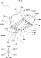
- FIG. 8 is an assembly diagram showing a procedure of assembling the battery packaging container 10 shown in FIG. 1 from the expanded state shown in FIG. 2 , the procedure being a fourth assembling step.
- FIG. 9 is an assembly diagram showing a procedure of assembling the battery packaging container 10 shown in FIG. 1 from the expanded state shown in FIG. 2 , the procedure being a fifth assembling step.
- the first lateral wall 31 is bent at the bottom wall front bending line 21a
- the second lateral wall 32 is bent at the bottom wall back bending line 22a
- the third lateral wall 33 is bent at the bottom wall left bending line 23a
- the fourth lateral wall 34 is bent at the bottom wall right bending line 24a.
- the partition wall 40 is bent at the first lateral wall front bending line 31a
- the left lateral edge support wall 51 and the right lateral edge support wall 52 are bent at the first folding perforation 53
- the battery contact portion 55a of the base part 55 is bent at the root portion front bending line 43b
- the partition wall support portion 55b of the base part 55 is bent at the second folding perforation 55c.
- the lid 60 is bent at the second lateral wall back bending line 32c
- the first flap 80 is bent at the third lateral wall left bending line 33b
- the second flap 90 is bent at the fourth lateral wall right bending line 34b.
- the engagement protrusion 42b and the holding protrusion 61 may be folded.
- the first lateral wall 31 is made to rise upward from the bottom wall front edge 21.
- the engagement protrusion 42b of the partition wall 40 is inserted into the second lateral wall engagement hole 32a of the second lateral wall 32.
- the partition wall 40 is held to the second lateral wall 32, so that the partition wall 40 is maintained in the state of extending diagonally from the first lateral wall front edge 31b to the bottom wall back edge 22.
- the battery contact portion 55a of the base part 55 extends downward from the root portion 43, and the partition wall support portion 55b is in contact with the bottom wall 20 and the first lateral wall 31.
- the battery 100 is stored in the storage hole 41 of the partition wall 40. Specifically, the battery 100 is stored in the storage hole 41 from the side of the end portion 42 to the side of the root portion 43 of the partition wall 40. Note that FIG. 7 shows the state before the battery 100 is fully stored in the storage hole 41.
- the front side and both the left and right sides of the battery 100 are held from above by the left root lateral portion 44b and the right root lateral portion 45b in the partition wall 40 ( FIGS. 3 and 4 ).
- the front end portion of the battery 100 the upper portion of the battery 100 is held from the front side by the root portion 43 and the battery contact portion 55a ( FIG. 3 and FIG. 4 ).
- the lower portion of the battery 100 is further held from the back side by the end portion 42 ( FIG. 4 ) .
- the third lateral wall 33 is made to rise upward from the bottom wall left edge 23, and the fourth lateral wall 34 is made to rise upward from the bottom wall right edge 24.
- the first flap 80 and the second flap 90 are folded, and the partition wall 40 is covered from above by the first flap 80 and the second flap 90.
- the battery 100 is held from above by the first flap 80 and the second flap 90 ( FIG. 3 ).
- the second lateral wall 32 is made to rise upward from the bottom wall back edge 22.
- the lid 60 is folded, and the holding protrusion 61 of the lid 60 is inserted into the partition wall back cut 40c of the partition wall 40, and the lid 60 is held to the partition wall 40.
- the battery 100 is held from above by the lid 60 in addition to the first flap 80 and the second flap 90 ( FIGS. 3 and 4 ).
- the bottom wall 20, the first lateral wall 31, the second lateral wall 32, the partition wall 40, and the lid 60 are integrally formed.
- the partition wall 40 extends diagonally from the first lateral wall front edge 31b of the first lateral wall 31 toward the bottom wall back edge 22 of the bottom wall 20.
- the partition wall 40 also includes the storage hole 41 to store the battery 100, the storage hole 41 being defined by the end portion 42 of the partition wall 40, the root portion 43 located on an opposite side of the end portion 42, and the left lateral portion 44 and the right lateral portion 45 that connect the end portion 42 and the root portion 43.
- the lid 60 further extends from the second lateral wall back edge 32b of the second lateral wall 32 to cover the partition wall 40 from above.
- the bottom wall 20, the first lateral wall 31, the second lateral wall 32, the partition wall 40, and the lid 60 are integrally formed, i.e., formed from one blank.
- the upper portion of the battery 100 is supported by the root portion 43 of the partition wall 40, and the lower portion of the battery 100 is supported by the end portion 42 of the partition wall 40.
- the battery 100 stored in the storage hole 41 is covered with the lid 60 from above.
- the battery packaging container 10 makes it possible to reduce the number of assembling steps and the number of parts.
- Supporting the battery 100 with the partition wall 40 and the lid 60 allows stable storage of the battery.
- the battery 100 can be restrained from moving while being conveyed, for example, and thereby damage of the battery 100 can be reduced.
- the lid 60 is opened, the upper portion of the battery 100 in the vicinity of the end portion 42 of the partition wall 40 is exposed without being supported by the partition wall 40. This makes it easy for a user to store and remove the battery 100.
- Each width of the left lateral portion 44 and the right lateral portion 45 (a pair of lateral portions) in the partition wall 40 is formed to be wider toward the side of the root portion 43 from the side of the end portion 42.
- the width W2 in the right-left direction in the left root lateral portion 44b is formed to be gradually wider toward the back side from the front side
- the width W4 in the right-left direction in the right root lateral portion 45b is formed to be gradually wider toward the back side from the front side.
- the battery 100 can be restrained from moving while being conveyed, for example, and thereby damage of the battery 100 can be reduced.
- the left lateral edge support wall 51 and the right lateral edge support wall 52 extend upward from at least both the lateral edges 42c, 42d in the end portion 42 to support the lid 60 in the state where the battery packaging container 10 is assembled ( FIGS. 3 and 4 ). Specifically, in the state where the battery 100 is housed in the storage hole 41, the left lateral edge support wall 51 and the right lateral edge support wall 52 are in contact with the first flap 80 and the second flap 90 to support the lid 60 through the first flap 80 and the second flap 90. Accordingly, even in the case where, for example, an impact is applied to the lid 60 of the battery packaging container 10 while the battery 100 is conveyed, the left lateral edge support wall 51 and the right lateral edge support wall 52 receive the impact, and the impact is distributed. This makes it possible to avoid the impact directly transmitted to the battery 100, and to thereby prevent damage of the battery 100.
- the base part 55 In the state where the battery packaging container 10 is assembled, the base part 55 extends downward from the root portion 43 of the partition wall 40 and comes into contact with the bottom wall 20. Hence, in the state where the battery packaging container 10 is assembled, the battery contact portion 55a of the base part 55 is in contact with the battery 100, and the partition wall support portion 55b of the base part 55 is in contact with the bottom wall 20 and the first lateral wall 31. Therefore, the battery 100 can be stably fixed by the battery contact portion 55a. Hence, for example, the battery 100 can be restrained from moving while being conveyed, and thereby damage of the battery 100 can be reduced.
- the partition wall support portion 55b receives the impact, and the impact is distributed. This makes it possible to avoid the impact directly transmitted to the battery 100, and to thereby prevent damage of the battery 100.
- the first flap 80 extends from the upper end of the third lateral wall 33 to partially cover the partition wall 40 from above
- the second flap 90 extends from the upper end of the fourth lateral wall 34 to partially cover the partition wall 40 from above.
- the engagement protrusion 42b of the partition wall 40 is inserted into the second lateral wall engagement hole 32a, and holds the partition wall 40 to the second lateral wall 32.
- the partition wall 40 can be held to the second lateral wall 32 by simply inserting the engagement protrusion 42b into the second lateral wall engagement hole 32a. Therefore, the battery packaging container 10 can be assembled easily.
- the battery packaging container 11 according to the second embodiment is different from the battery packaging container 10 according to the first embodiment in that the pair of lateral edge support walls 50 is not provided and a leading edge support wall 57 is provided as will be described later.
- description of the component members having functions identical or similar to those of the battery packaging container 10 according to the first embodiment is omitted, and only the component members related to different functions will be designated by reference signs for description.
- the battery packaging container 11 further includes the leading edge support wall 57 formed integrally with the partition wall 40.
- the leading edge support wall 57 is approximately rectangular. Specifically, the leading edge support wall 57 has corner portions 57b with rounded corners on both right and left ends on the front side.
- the leading edge support wall 57 are linked to the partition wall 40 via a third folding perforation 57c. In the state where the battery packaging container 11 is assembled, the leading edge support wall 57 is bent at the third folding perforation 57c, and extends upward from a leading edge 42a of the end portion 42 and supports the lid 60.
- the leading edge support wall 57 is in contact with the lid 60 at a front edge 57a located on the front side of the tip edge support wall 57 to support the lid 60.
- the engagement protrusion 42b provided in the end portion 42 is not linked to the leading edge support wall 57. Accordingly, in the state where the leading edge support wall 57 is bent at the third folding perforation 57c, the engagement protrusion 42b protrudes forward from the leading edge 42a of the end portion 42.
- the leading edge support wall 57 extends upward from the leading edge 42a of the end portion 42, and supports the lid 60 in the state where the battery packaging container 11 is assembled. Specifically, in the state where the battery is housed in the storage hole 41, the leading edge support wall 57 is in direct contact with the lid 60 to support the lid 60. Hence, in the case where, for example, an impact is applied to the lid 60 of the battery packaging container 11 while the battery is conveyed, the leading edge support wall 57 receives the impact, and the impact is distributed. This makes it possible to avoid the impact directly transmitted to the battery, and to thereby prevent damage of the battery.
- the present invention is not limited to the battery packaging containers 10, 11 according to the embodiments disclosed.
- the present invention embraces all aspects within the concept of the present invention and the claims.
- the respective component members may be selectively combined as appropriate to achieve the objective of the present invention or at least some of the effects thereof.
- the shape of the battery packaging containers 10, 11 is not limited to the rectangular parallelepiped shape, and any shape is possible as long as the battery can be packaged.
- the bending lines in the battery packaging containers 10, 11 are not limited to straight lines, and may be wave lines or the like, for example. It is also possible to provide a battery packaging container including all the component members including the left lateral edge support wall 51 and the right lateral edge support wall 52 according to the first embodiment and the leading edge support wall 57 according to the second embodiment.
Landscapes
- Engineering & Computer Science (AREA)
- Mechanical Engineering (AREA)
- Chemical & Material Sciences (AREA)
- Chemical Kinetics & Catalysis (AREA)
- Electrochemistry (AREA)
- General Chemical & Material Sciences (AREA)
- Cartons (AREA)
- Battery Mounting, Suspending (AREA)
- Packages (AREA)
Abstract
Description
- The present invention relates to a battery packaging container.
- Packaging devices that package electronic components, batteries, etc., have been known. For example, a packaging device disclosed in
JP H08-156993 A - According to the invention disclosed in
JP H08-156993 A - The present invention has been made in view of such issues, and an objective of the present invention is to provide a battery packaging container that achieves reduction in the number of assembling steps and reduction in the number of parts.
- In order to accomplish the above, a battery packaging container of the present invention comprises: a plate-shaped bottom wall; a first lateral wall formed integrally with the bottom wall and extending upward from a first edge that is part of a contour of the bottom wall; a second lateral wall formed integrally with the bottom wall and extending upward from a second edge that is a portion opposing to the first edge in the contour of the bottom wall; a partition wall formed integrally with the first lateral wall and extending diagonally from an upper end of the first lateral wall toward the second edge of the bottom wall ; and a lid formed integrally with the second lateral wall and extending from an upper end of the second lateral wall to cover the partition wall from above. The partition wall includes a storage hole to store a battery, the storage hole being defined by an end portion of the partition wall, a root portion located on an opposite side of the end portion, and a pair of lateral portions connecting the end portion and the root portion.
- In a second aspect of the present invention according to the first aspect, each width of the lateral portions in the pair of the lateral portions in the partition wall is formed to be wider toward a side of the root portion from a side of the end portion.
- A third aspect of the present invention according to the first aspect or the second aspect further includes a pair of lateral edge support walls formed integrally with the partition wall, the lateral edge support walls extending upward from at least both lateral edges of the end portion to support the lid.
- A fourth aspect of the present invention according to any one of the first aspect to the third aspect further includes a leading edge support wall formed integrally with the partition wall, the leading edge support wall extending upward from a leading edge of the end portion to support the lid.
- A fifth aspect of the present invention according to any one of the first aspect to the fourth aspect further includes a base part formed integrally with the partition wall, the base part extending downward from the root portion and being in contact with the bottom wall.
- A sixth aspect of the present invention according to any one of the first aspect to the fifth aspect further includes: a third lateral wall formed integrally with the bottom wall and extending upward from a third edge that is a portion connecting the first edge and the second edge in the contour of the bottom wall; a fourth lateral wall formed integrally with the bottom wall and extending upward from a fourth edge that is a portion opposing to the third edge in the contour of the bottom wall; a first flap formed integrally with the third lateral wall and extending from an upper end of the third lateral wall to partially cover the partition wall from above; and a second flap formed integrally with the fourth lateral wall and extending from an upper end of the fourth lateral wall to partially cover the partition wall part from above.
- In a seventh aspect of the present invention according to any one of the first aspect to the sixth aspect, the second lateral wall includes an engagement hole extending through the second lateral wall. The partition wall includes an engagement protrusion that protrudes from a leading edge of the end portion and inserted into the engagement hole.
-
-
FIG. 1 is a perspective view showing a battery packaging container according to a first embodiment; -
FIG. 2 is an expanded view showing the expanded battery packaging container shown inFIG. 1 ; -
FIG. 3 is a cross-sectional view along a cross-section A-A inFIG. 1 ; -
FIG. 4 is a cross-sectional view along a cross-section B-B inFIG. 1 ; -
FIG. 5 is an assembly diagram showing a procedure of assembling the battery packaging container shown inFIG. 1 from the expanded state shown inFIG. 2 , the procedure being a first assembling step; -
FIG. 6 is an assembly diagram showing a procedure of assembling the battery packaging container shown inFIG. 1 from the expanded state shown inFIG. 2 , the procedure being a second assembling step; -
FIG. 7 is an assembly diagram showing a procedure of assembling the battery packaging container shown inFIG. 1 from the expanded state shown inFIG. 2 , the procedure being a third assembling step; -
FIG. 8 is an assembly diagram showing a procedure of assembling the battery packaging container shown inFIG. 1 from the expanded state shown inFIG. 2 , the procedure being a fourth assembling step; -
FIG. 9 is an assembly diagram showing a procedure of assembling the battery packaging container shown inFIG. 1 from the expanded state shown inFIG. 2 , the procedure being a fifth assembling step; and -
FIG. 10 is an expanded view showing a battery packaging container according to a second embodiment. - Embodiments of the present invention will be described below with reference to the drawings.
-
FIG. 1 is a perspective view showing abattery packaging container 10 according to a first embodiment.FIG. 2 is an expanded view showing the expandedbattery packaging container 10 shown inFIG. 1 .FIG. 3 is a cross-sectional view along a cross-section A-A inFIG. 1 .FIG. 4 is a cross-sectional view along a cross-section B-B inFIG. 1 . - For the convenience of explanation, in the
battery packaging container 10, a side on which abottom wall 20 is arranged is defined as "bottom", and a side on which alid 60 is arranged in the state where the assembly of thebattery packaging container 10 is completed is defined as "top". In thebattery packaging container 10, a side on which afirst flap 80 is arranged is defined as "left" and a side on which asecond flap 90 is arranged is defined as "right". In addition, a direction perpendicular to a top-bottom direction and a right-left direction is defined as "front" and "back". Hereinafter, the terms "front", "back", "left", "right", "top" and "bottom" shown in the drawings are all based on these definitions. - The
battery packaging container 10 in the present embodiment is in an approximately rectangular parallelepiped shape in an assembled state (FIG. 1 ). Thebattery packaging container 10 is configured from a single paper template that is formed by punching out a cardboard or the like by a press or other machines (FIG. 2 ). As shown inFIG. 2 , thebattery packaging container 10 includes a plate-shaped bottom wall 20, a firstlateral wall 31 formed integrally with thebottom wall 20, a secondlateral wall 32 formed integrally with the bottom wall, a thirdlateral wall 33 formed integrally with thebottom wall 20, a fourthlateral wall 34 formed integrally with thebottom wall 20, apartition wall 40 formed integrally with the firstlateral wall 31, a pair of lateraledge support walls 50 formed integrally with thepartition wall 40, abase 55 formed integrally with thepartition wall 40, alid 60 formed integrally with the secondlateral wall 32, afirst flap 80 formed integrally with the thirdlateral wall 33, and asecond flap 90 formed integrally with the fourthlateral wall 34. Thebattery packaging container 10 is widely used for packaging batteries, and used for a variety of applications, such as for conveying batteries, and for displaying batteries. - The
bottom wall 20 is rectangular as shown inFIG. 2 . Thebottom wall 20 is linked to the firstlateral wall 31 at a bottomwall front edge 21 located on the front side of thebottom wall 20 via a bottom wallfront bending line 21a extending in a right-left direction. Thebottom wall 20 is also linked to the secondlateral wall 32 at a bottomwall back edge 22 located on the back side of thebottom wall 20 via a bottom wall backbending line 22a extending in the right-left direction. Thebottom wall 20 is also linked to the thirdlateral wall 33 at a bottom wallleft edge 23 located on the left side of thebottom wall 20 via a bottom wall leftbending line 23a extending in a front-back direction. Thebottom wall 20 is also linked to the fourthlateral wall 34 at a bottom wall right edge 24 located on the right side of thebottom wall 20 via a bottom wallright bending line 24a extending in the front-back direction. Thebottom wall 20 also includes a bottom wall front cut 21b in the vicinity of the bottomwall front edge 21. The bottom wall front cut 21b extends in the right-left direction in parallel to the bottom wallfront bending line 21a and extends through thebottom wall 20 in the top-bottom direction. - As shown in
FIGS. 1 and2 , the firstlateral wall 31 is rectangular. In the state where thebattery packaging container 10 is assembled, the firstlateral wall 31 extends upward from the bottom wall front edge 21 (first edge) that is part of a contour of thebottom wall 20. Specifically, the firstlateral wall 31 is bent at the bottom wallfront bending line 21a to extend upward from the bottomwall front edge 21. As shown inFIG. 2 , the firstlateral wall 31 is linked to thepartition wall 40 at a first lateralwall front edge 31b located on the front side of the firstlateral wall 31 via a first lateral wallfront bending line 31a extending in the right-left direction. In addition, the firstlateral wall 31 has a pair ofperforations 31c, which extends forward continuously from the bottomwall front cut 21b. - As shown in
FIG. 2 , the secondlateral wall 32 is rectangular. In the state where thebattery packaging container 10 is assembled, the secondlateral wall 32 extends upward from the bottom wall back edge 22 (second edge) that is a portion on the side opposing to the bottomwall front edge 21 in the contour of thebottom wall 20. Specifically, the secondlateral wall 32 is bent at the bottom wall back bendingline 22a to extend upward from the bottom wall backedge 22. As shown inFIG. 2 , the secondlateral wall 32 includes a second lateralwall engagement hole 32a (engagement hole) extending through the secondlateral wall 32. Specifically, in the vicinity of the bottom wall backedge 22, the second lateralwall engagement hole 32a extends in the right-left direction in parallel to the bottom wall back bendingline 22a, and extends through the secondlateral wall 32 in the top-bottom direction. As shown inFIG. 2 , the secondlateral wall 32 is linked to thelid 60 at a second lateral wall backedge 32b located on the back side of the secondlateral wall 32 via a second lateral wall back bendingline 32c extending in the right-left direction. - As shown in
FIG. 2 , the thirdlateral wall 33 and the fourthlateral wall 34 are rectangular. In the state where thebattery packaging container 10 is assembled, the thirdlateral wall 33 extends upward from the bottom wall left edge 23 (third edge) that is a portion connecting the bottomwall front edge 21 and the bottom wall backedge 22 in the contour of thebottom wall 20. Specifically, the thirdlateral wall 33 is bent at the bottom wall left bendingline 23a to extend upward from the bottom wall leftedge 23. The fourthlateral wall 34 extends upward from the bottom wall right edge 24 (fourth edge) that is a portion on the side opposing to the bottom wall leftedge 23 in the contour of thebottom wall 20. Specifically, the fourthlateral wall 34 is bent at the bottom wall right bendingline 24a to extend upward from the bottom wall right edge 24. As shown inFIG. 2 , the thirdlateral wall 33 is linked to thefirst flap 80 at a third lateral wall leftedge 33a located on the left side of the thirdlateral wall 33 via a third lateral wall left bendingline 33b extending in the front-back direction. The fourthlateral wall 34 is linked to thesecond flap 90 at a fourth lateral wallright edge 34a located on the right side of the fourthlateral wall 34 via a fourth lateral wall right bendingline 34b extending in the front-back direction. - As shown in
FIG. 2 , thepartition wall 40 is approximately rectangular. As shown inFIGS. 3 and 4 , in the state where thebattery packaging container 10 is assembled, thepartition wall 40 extends diagonally from the first lateral wallfront edge 31b (upper end) of the firstlateral wall 31 toward the bottom wall backedge 22 of thebottom wall 20. Specifically, thepartition wall 40 is bent at the first lateral wallfront bending line 31a to extend diagonally from the first lateral wallfront edge 31b toward the bottom wall backedge 22. Thepartition wall 40 also includes astorage hole 41 to store abattery 100. Thestorage hole 41 is defined by aend portion 42 of thepartition wall 40, aroot portion 43 located on the opposite side of theend portion 42, a left lateral portion 44 (a pair of lateral portions) that connects theend portion 42 and theroot portion 43 on the left side, and a right lateral portion 45 (a pair of lateral portions) that connects theend portion 42 and theroot portion 43 on the right side. Theend portion 42 is a portion extending in the right-left direction on the front side of thestorage hole 41. Theroot portion 43 is a portion extending in the right-left direction at the back of thestorage hole 41. The leftlateral portion 44 is a portion extending in the front-back direction on the left side of thestorage hole 41. The rightlateral portion 45 is a portion extending in the front-back direction on the right side of thestorage hole 41. More specifically, as shown inFIGS. 3 and 4 , in the state where thebattery packaging container 10 is assembled, theroot portion 43 is a portion extending horizontally or approximately horizontally backward from the first lateral wallfront edge 31b. The leftlateral portion 44 and the rightlateral portion 45 are portions extending diagonally from theroot portion 43 to the bottom wall backedge 22. Theend portion 42 is a portion in contact with thebottom wall 20 and the secondlateral wall 32. As shown inFIG. 2 , theroot portion 43 is linked to a base 55 at a rootportion front edge 43a located on the front side of theroot portion 43 via a root portionfront bending line 43b extending in the right-left direction. - As shown in
FIG. 2 , the leftlateral portion 44 of thepartition wall 40 is constituted of a left endlateral portion 44a located on the side of theend portion 42, and a leftroot lateral portion 44b located on the side of theroot portion 43. The rightlateral portion 45 of thepartition wall 40 is constituted of a rightend lateral portion 45a located on the side of theend portion 42, and a rightroot lateral portion 45b located on the side of theroot portion 43. Each width of the leftlateral portion 44 and the right lateral portion 45 (a pair of lateral portions) in thepartition wall 40 is formed to be wider toward the side of theroot portion 43 from the side of theend portion 42. Specifically, as shown inFIG. 2 , a width W1 in the right-left direction in the left endlateral portion 44a is formed to be a constant width, and a width W2 in the right-left direction in the leftroot lateral portion 44b is formed to be gradually wider toward the back side from the front side. Similarly, a width W3 in the right-left direction in the rightend lateral portion 45a is formed to be a constant width, and a width W4 in the right-left direction in the rightroot lateral portion 45b is formed to be gradually wider toward the back side from the front side. Note that the width W1 in the right-left direction in the left endlateral portion 44a and the width W3 in the right-left direction in the rightend lateral portion 45a may be identical to or different from each other. The width W2 in the right-left direction in the leftroot lateral portion 44b and the width W4 in the right-left direction in the rightroot lateral portion 45b may be identical to or different from each other. - As shown in
FIG. 2 , thepartition wall 40 includes anengagement protrusion 42b protruding from aleading edge 42a of theend portion 42. Specifically, as shown inFIG. 2 , theengagement protrusion 42b protrudes forward from theleading edge 42a, and is formed to be narrower toward the front side from the back side. In the state where thebattery packaging container 10 is assembled, theengagement protrusion 42b is inserted into the second lateralwall engagement hole 32a, and holds thepartition wall 40 to the secondlateral wall 32. Thepartition wall 40 also includes a partition wall back cut 40c in the vicinity of the first lateral wallfront edge 31b. The partition wall back cut 40c extends in the right-left direction in parallel to the first lateral wallfront bending line 31a and extends through thepartition wall 40 in the top-bottom direction. In the state where thebattery packaging container 10 is assembled, the partition wall back cut 40c receives a holdingprotrusion 61 of thelid 60 as will be described later. - As shown in
FIG. 2 , a pair of lateraledge support walls 50 is constituted of a left lateraledge support wall 51 located on the left side of thepartition wall 40 and a right lateraledge support wall 52 located on the right side of thepartition wall 40. The left lateraledge support wall 51 and the right lateraledge support wall 52 are each linked to thepartition wall 40 via afirst folding perforation 53. In the state where thebattery packaging container 10 is assembled, the left lateraledge support wall 51 and the right lateral edge support wall 52 (a pair of lateral edge support walls 50) extend upward from a leftlateral edge 40a located on the left side of thepartition wall 40 and a rightlateral edge 40b located on the right side of thepartition wall 40. Specifically, the left lateraledge support wall 51 is provided at a portion corresponding to theend portion 42 and the left endlateral portion 44a in the leftlateral edge 40a, and the right lateraledge support wall 52 is provided at a portion corresponding to theend portion 42 and the rightend lateral portion 45a in the rightlateral edge 40b. The left lateraledge support wall 51 and the right lateraledge support wall 52 may extend upward at least from both thelateral edges end portion 42, respectively. For example, the left lateraledge support wall 51 and the right lateraledge support wall 52 may be provided only in a portion of theend portion 42 in each of the leftlateral edge 40a and the rightlateral edge 40b. Both the lateral edges in theend portion 42 refer to the left lateral edge ofend portion 42c located on the left side of theend portion 42 and the right lateral edge ofend portion 42d located on the right side of theend portion 42. Each width of the left lateraledge support wall 51 and the right lateraledge support wall 52 are formed to be wider toward the front side from the back side (FIG. 2 ). Accordingly, in the state where thebattery packaging container 10 is assembled, the left lateraledge support wall 51 and the right lateraledge support wall 52 support the lid 60 (FIGS. 3 and 4 ). - As shown in
FIGS. 3 and 4 , in the state where thebattery packaging container 10 is assembled, thebase 55 extends downward from theroot portion 43 of thepartition wall 40 and is in contact with thebottom wall 20. Specifically, thebase 55 is constituted of abattery contact portion 55a that is in contact with the front side of thebattery 100, and a partitionwall support portion 55b that is in contact with thebottom wall 20 and the firstlateral wall 31. - As shown in
FIG. 2 , thebattery contact portion 55a of thebase 55 is linked to theroot portion 43 of thepartition wall 40 via the root portionfront bending line 43b. The partitionwall support portion 55b is also linked to thebattery contact portion 55a via asecond folding perforation 55c located on the front side of thebattery contact portion 55a. Thebattery contact portion 55a and the partitionwall support portion 55b are not linked to the leftlateral portion 44 and the rightlateral portion 45 of thepartition wall 40. This enables thebattery contact portion 55a to be bent along the root portionfront bending line 43b, and the partitionwall support portion 55b to be bent at thesecond folding perforation 55c. Hence, in the state where thebattery packaging container 10 is assembled, thebattery contact portion 55a is in contact with thebattery 100, and the partitionwall support portion 55b is in contact with thebottom wall 20 and the firstlateral wall 31 - As shown in
FIG. 2 , thelid 60 is approximately rectangular. Specifically, thelid 60 hascorner portions 60a with rounded corners on both right and left ends on the back side. As shown inFIGS. 3 and 4 , in the state where thebattery packaging container 10 is assembled, thelid 60 extends from the second lateral wall backedge 32b (upper end) of the secondlateral wall 32 to cover thepartition wall 40 from above. Specifically, thelid 60 is bent at the second lateral wall back bendingline 32c to extend forward from the second lateral wall backedge 32b. Thelid 60 includes the holdingprotrusion 61 protruding backward from aback edge 60c of thelid 60. In the state where thebattery packaging container 10 is assembled, the holdingprotrusion 61 is inserted into the partition wall back cut 40c of thepartition wall 40 and holds thelid 60 to thepartition wall 40. - As shown in
FIG. 2 , thefirst flap 80 is approximately rectangular. Specifically, thefirst flap 80 has a designatedfirst flap notch 80a in a front-side and left-side end portion. In the state where thebattery packaging container 10 is assembled, thefirst flap 80 extends from the upper end of the thirdlateral wall 33 to partially cover thepartition wall 40 from above. Specifically, thefirst flap 80 is bent at the third lateral wall left bendingline 33b to extend rightward from the third lateral wall leftedge 33a. Thefirst flap notch 80a is formed to avoid the partition wall back cut 40c in the state where thebattery packaging container 10 is assembled. - As shown in
FIG. 2 , thesecond flap 90 is approximately rectangular. Specifically, thesecond flap 90 has a designatedsecond flap notch 90a in a front-side and right-side end portion. In the state where thebattery packaging container 10 is assembled, thesecond flap 90 extends from the upper end of the fourthlateral wall 34 to partially cover thepartition wall 40 from above. Specifically, thesecond flap 90 is bent at the fourth lateral wall right bendingline 34b to extend leftward from the fourth lateral wallright edge 34a. Thesecond flap notch 90a is formed to avoid the partition wall back cut 40c in the state where thebattery packaging container 10 is assembled. - Description is now given of a method of assembling the
battery packaging container 10 according to the first embodiment.FIG. 5 is an assembly diagram showing a procedure of assembling thebattery packaging container 10 shown inFIG. 1 from the expanded state shown inFIG. 2 , the procedure being a first assembling step.FIG. 6 is an assembly diagram showing a procedure of assembling thebattery packaging container 10 shown inFIG. 1 from the expanded state shown inFIG. 2 , the procedure being a second assembling step.FIG. 7 is an assembly diagram showing a procedure of assembling thebattery packaging container 10 shown inFIG. 1 from the expanded state shown inFIG. 2 , the procedure being a third assembling step.FIG. 8 is an assembly diagram showing a procedure of assembling thebattery packaging container 10 shown inFIG. 1 from the expanded state shown inFIG. 2 , the procedure being a fourth assembling step.FIG. 9 is an assembly diagram showing a procedure of assembling thebattery packaging container 10 shown inFIG. 1 from the expanded state shown inFIG. 2 , the procedure being a fifth assembling step. - First, as shown in
FIG. 5 , the firstlateral wall 31 is bent at the bottom wallfront bending line 21a, the secondlateral wall 32 is bent at the bottom wall back bendingline 22a, the thirdlateral wall 33 is bent at the bottom wall left bendingline 23a, and the fourthlateral wall 34 is bent at the bottom wall right bendingline 24a. Furthermore, thepartition wall 40 is bent at the first lateral wallfront bending line 31a, the left lateraledge support wall 51 and the right lateraledge support wall 52 are bent at thefirst folding perforation 53, thebattery contact portion 55a of thebase part 55 is bent at the root portionfront bending line 43b, and the partitionwall support portion 55b of thebase part 55 is bent at thesecond folding perforation 55c. In addition, thelid 60 is bent at the second lateral wall back bendingline 32c, thefirst flap 80 is bent at the third lateral wall left bendingline 33b, and thesecond flap 90 is bent at the fourth lateral wall right bendingline 34b. In addition, theengagement protrusion 42b and the holdingprotrusion 61 may be folded. - Next, as shown in
FIG. 6 , the firstlateral wall 31 is made to rise upward from the bottomwall front edge 21. Then, theengagement protrusion 42b of thepartition wall 40 is inserted into the second lateralwall engagement hole 32a of the secondlateral wall 32. As a consequence, thepartition wall 40 is held to the secondlateral wall 32, so that thepartition wall 40 is maintained in the state of extending diagonally from the first lateral wallfront edge 31b to the bottom wall backedge 22. In this case, thebattery contact portion 55a of thebase part 55 extends downward from theroot portion 43, and the partitionwall support portion 55b is in contact with thebottom wall 20 and the firstlateral wall 31. - Then, as shown in
FIG. 7 , thebattery 100 is stored in thestorage hole 41 of thepartition wall 40. Specifically, thebattery 100 is stored in thestorage hole 41 from the side of theend portion 42 to the side of theroot portion 43 of thepartition wall 40. Note thatFIG. 7 shows the state before thebattery 100 is fully stored in thestorage hole 41. Once thebattery 100 is fully stored in thestorage hole 41, the front side and both the left and right sides of thebattery 100 are held from above by the leftroot lateral portion 44b and the rightroot lateral portion 45b in the partition wall 40 (FIGS. 3 and 4 ). As for the front end portion of thebattery 100, the upper portion of thebattery 100 is held from the front side by theroot portion 43 and thebattery contact portion 55a (FIG. 3 and FIG. 4 ). As for the back end portion of thebattery 100, the lower portion of thebattery 100 is further held from the back side by the end portion 42 (FIG. 4 ) . - Next, as shown in
FIG. 8 , the thirdlateral wall 33 is made to rise upward from the bottom wall leftedge 23, and the fourthlateral wall 34 is made to rise upward from the bottom wall right edge 24. Then, thefirst flap 80 and thesecond flap 90 are folded, and thepartition wall 40 is covered from above by thefirst flap 80 and thesecond flap 90. As a result, thebattery 100 is held from above by thefirst flap 80 and the second flap 90 (FIG. 3 ). - Next, as shown in
FIG. 9 , the secondlateral wall 32 is made to rise upward from the bottom wall backedge 22. Then, thelid 60 is folded, and the holdingprotrusion 61 of thelid 60 is inserted into the partition wall back cut 40c of thepartition wall 40, and thelid 60 is held to thepartition wall 40. As a result, thebattery 100 is held from above by thelid 60 in addition to thefirst flap 80 and the second flap 90 (FIGS. 3 and 4 ). - Description is now given of the operation and effects of the
battery packaging container 10 according to the first embodiment. In thebattery packaging container 10 according to the first embodiment, thebottom wall 20, the firstlateral wall 31, the secondlateral wall 32, thepartition wall 40, and thelid 60 are integrally formed. Thepartition wall 40 extends diagonally from the first lateral wallfront edge 31b of the firstlateral wall 31 toward the bottom wall backedge 22 of thebottom wall 20. Thepartition wall 40 also includes thestorage hole 41 to store thebattery 100, thestorage hole 41 being defined by theend portion 42 of thepartition wall 40, theroot portion 43 located on an opposite side of theend portion 42, and the leftlateral portion 44 and the rightlateral portion 45 that connect theend portion 42 and theroot portion 43. Thelid 60 further extends from the second lateral wall backedge 32b of the secondlateral wall 32 to cover thepartition wall 40 from above. Thus, in thebattery packaging container 10 according to the first embodiment, thebottom wall 20, the firstlateral wall 31, the secondlateral wall 32, thepartition wall 40, and thelid 60 are integrally formed, i.e., formed from one blank. In thebattery packaging container 10, in the state where thebattery 100 is stored in thestorage hole 41, the upper portion of thebattery 100 is supported by theroot portion 43 of thepartition wall 40, and the lower portion of thebattery 100 is supported by theend portion 42 of thepartition wall 40. Moreover, thebattery 100 stored in thestorage hole 41 is covered with thelid 60 from above. Therefore, forming thebattery packaging container 10 from a single blank makes it possible to reduce the number of assembling steps and the number of parts. Supporting thebattery 100 with thepartition wall 40 and thelid 60 allows stable storage of the battery. Hence, thebattery 100 can be restrained from moving while being conveyed, for example, and thereby damage of thebattery 100 can be reduced. In addition, in the state where thelid 60 is opened, the upper portion of thebattery 100 in the vicinity of theend portion 42 of thepartition wall 40 is exposed without being supported by thepartition wall 40. This makes it easy for a user to store and remove thebattery 100. - Each width of the left
lateral portion 44 and the right lateral portion 45 (a pair of lateral portions) in thepartition wall 40 is formed to be wider toward the side of theroot portion 43 from the side of theend portion 42. Specifically, the width W2 in the right-left direction in the leftroot lateral portion 44b is formed to be gradually wider toward the back side from the front side, and the width W4 in the right-left direction in the rightroot lateral portion 45b is formed to be gradually wider toward the back side from the front side. Hence, in the state where thebattery 100 is fully housed in thestorage hole 41, the front side and both the left and right sides of thebattery 100 are held from above by the leftroot lateral portion 44b and the rightroot lateral portion 45b in the partition wall 40 (FIGS. 3 and 4 ) . Therefore, it is possible to stably store thebattery 100 with the leftlateral portion 44 and the rightlateral portion 45 in thepartition wall 40. Hence, thebattery 100 can be restrained from moving while being conveyed, for example, and thereby damage of thebattery 100 can be reduced. - Moreover, the left lateral
edge support wall 51 and the right lateraledge support wall 52 extend upward from at least both thelateral edges end portion 42 to support thelid 60 in the state where thebattery packaging container 10 is assembled (FIGS. 3 and 4 ). Specifically, in the state where thebattery 100 is housed in thestorage hole 41, the left lateraledge support wall 51 and the right lateraledge support wall 52 are in contact with thefirst flap 80 and thesecond flap 90 to support thelid 60 through thefirst flap 80 and thesecond flap 90. Accordingly, even in the case where, for example, an impact is applied to thelid 60 of thebattery packaging container 10 while thebattery 100 is conveyed, the left lateraledge support wall 51 and the right lateraledge support wall 52 receive the impact, and the impact is distributed. This makes it possible to avoid the impact directly transmitted to thebattery 100, and to thereby prevent damage of thebattery 100. - In the state where the
battery packaging container 10 is assembled, thebase part 55 extends downward from theroot portion 43 of thepartition wall 40 and comes into contact with thebottom wall 20. Hence, in the state where thebattery packaging container 10 is assembled, thebattery contact portion 55a of thebase part 55 is in contact with thebattery 100, and the partitionwall support portion 55b of thebase part 55 is in contact with thebottom wall 20 and the firstlateral wall 31. Therefore, thebattery 100 can be stably fixed by thebattery contact portion 55a. Hence, for example, thebattery 100 can be restrained from moving while being conveyed, and thereby damage of thebattery 100 can be reduced. In the case where, for example, an impact is applied to thebottom wall 20 of thebattery packaging container 10 while thebattery 100 is conveyed, the partitionwall support portion 55b receives the impact, and the impact is distributed. This makes it possible to avoid the impact directly transmitted to thebattery 100, and to thereby prevent damage of thebattery 100. - The
first flap 80 extends from the upper end of the thirdlateral wall 33 to partially cover thepartition wall 40 from above, and thesecond flap 90 extends from the upper end of the fourthlateral wall 34 to partially cover thepartition wall 40 from above. Specifically, in the state where thebattery 100 is housed in thestorage hole 41, thebattery 100 is held from above by thefirst flap 80 and thesecond flap 90. Therefore, supporting thebattery 100 by thefirst flap 80 and thesecond flap 90 allows stable storage of the battery. Hence, for example, thebattery 100 can be restrained from moving while being conveyed and thereby damage of thebattery 100 can be reduced. - In the state where the
battery packaging container 10 is assembled, theengagement protrusion 42b of thepartition wall 40 is inserted into the second lateralwall engagement hole 32a, and holds thepartition wall 40 to the secondlateral wall 32. Thus, in the assembly process of thebattery packaging container 10, thepartition wall 40 can be held to the secondlateral wall 32 by simply inserting theengagement protrusion 42b into the second lateralwall engagement hole 32a. Therefore, thebattery packaging container 10 can be assembled easily. - Description is now given of a
battery packaging container 11 according to a second embodiment. Thebattery packaging container 11 according to the second embodiment is different from thebattery packaging container 10 according to the first embodiment in that the pair of lateraledge support walls 50 is not provided and a leadingedge support wall 57 is provided as will be described later. Hereinafter, description of the component members having functions identical or similar to those of thebattery packaging container 10 according to the first embodiment is omitted, and only the component members related to different functions will be designated by reference signs for description. - As shown in
FIG. 10 , thebattery packaging container 11 further includes the leadingedge support wall 57 formed integrally with thepartition wall 40. The leadingedge support wall 57 is approximately rectangular. Specifically, the leadingedge support wall 57 hascorner portions 57b with rounded corners on both right and left ends on the front side. The leadingedge support wall 57 are linked to thepartition wall 40 via athird folding perforation 57c. In the state where thebattery packaging container 11 is assembled, the leadingedge support wall 57 is bent at thethird folding perforation 57c, and extends upward from aleading edge 42a of theend portion 42 and supports thelid 60. Specifically, the leadingedge support wall 57 is in contact with thelid 60 at afront edge 57a located on the front side of the tipedge support wall 57 to support thelid 60. Note that theengagement protrusion 42b provided in theend portion 42 is not linked to the leadingedge support wall 57. Accordingly, in the state where the leadingedge support wall 57 is bent at thethird folding perforation 57c, theengagement protrusion 42b protrudes forward from theleading edge 42a of theend portion 42. - Description is now given of the operation and effects of the
battery packaging container 11 according to the second embodiment. In thebattery packaging container 11 according to the second embodiment, the leadingedge support wall 57 extends upward from theleading edge 42a of theend portion 42, and supports thelid 60 in the state where thebattery packaging container 11 is assembled. Specifically, in the state where the battery is housed in thestorage hole 41, the leadingedge support wall 57 is in direct contact with thelid 60 to support thelid 60. Hence, in the case where, for example, an impact is applied to thelid 60 of thebattery packaging container 11 while the battery is conveyed, the leadingedge support wall 57 receives the impact, and the impact is distributed. This makes it possible to avoid the impact directly transmitted to the battery, and to thereby prevent damage of the battery. - Although the preferred embodiments of the present invention have been described in the foregoing, the present invention is not limited to the
battery packaging containers battery packaging containers battery packaging containers edge support wall 51 and the right lateraledge support wall 52 according to the first embodiment and the leadingedge support wall 57 according to the second embodiment.
Claims (7)
- A battery packaging container, comprising:a plate-shaped bottom wall;a first lateral wall formed integrally with the bottom wall and extending upward from a first edge that is part of a contour of the bottom wall;a second lateral wall formed integrally with the bottom wall and extending upward from a second edge that is a portion of a side opposing to the first edge in the contour of the bottom wall;a partition wall formed integrally with the first lateral wall and extending diagonally from an upper end of the first lateral wall toward the second edge of the bottom wall; anda lid formed integrally with the second lateral wall and extending from an upper end of the second lateral wall to cover the partition wall from above, whereinthe partition wall includes a storage hole to store a battery, the storage hole being defined by an end portion of the partition wall, a root portion located on an opposite side of the end portion, and a pair of lateral portions connecting the end portion and the root portion.
- The battery packaging container according to claim 1, wherein each width of the lateral portions in the pair of the lateral portions in the partition wall is formed to be wider toward a side of the root portion from a side of the end portion.
- The battery packaging container according to claim 1 or 2, further comprising a pair of lateral edge support walls formed integrally with the partition wall, the lateral edge support walls extending upward from at least both lateral edges of the end portion to support the lid.
- The battery packaging container according to one of claims 1 to 3, further comprising a leading edge support wall formed integrally with the partition wall, the leading edge support wall extending upward from a leading edge of the end portion to support the lid.
- The battery packaging container according to one of claims 1 to 4, further comprising a base part formed integrally with the partition wall, the base part extending downward from the root portion and being in contact with the bottom wall.
- The battery packaging container according to one of claims 1 to 5, further comprising:a third lateral wall formed integrally with the bottom wall and extending upward from a third edge that is a portion connecting the first edge and the second edge in the contour of the bottom wall;a fourth lateral wall formed integrally with the bottom wall and extending upward from a fourth edge that is a portion opposing to the third edge in the contour of the bottom wall;a first flap formed integrally with the third lateral wall and extending from an upper end of the third lateral wall to partially cover the partition wall from above; anda second flap formed integrally with the fourth lateral wall and extending from an upper end of the fourth lateral wall to partially cover the partition wall from above.
- The battery packaging container according to one of claims 1 to 6, whereinthe second lateral wall includes an engagement hole extending through the second lateral wall, andthe partition wall includes an engagement protrusion that protrudes from a leading edge of the end portion and is inserted into the engagement hole.
Applications Claiming Priority (1)
| Application Number | Priority Date | Filing Date | Title |
|---|---|---|---|
| JP2021021018A JP7509708B2 (en) | 2021-02-12 | 2021-02-12 | Battery packaging container |
Publications (2)
| Publication Number | Publication Date |
|---|---|
| EP4044344A1 true EP4044344A1 (en) | 2022-08-17 |
| EP4044344B1 EP4044344B1 (en) | 2025-10-29 |
Family
ID=80118837
Family Applications (1)
| Application Number | Title | Priority Date | Filing Date |
|---|---|---|---|
| EP22154527.0A Active EP4044344B1 (en) | 2021-02-12 | 2022-02-01 | Battery packaging container |
Country Status (4)
| Country | Link |
|---|---|
| US (1) | US11932466B2 (en) |
| EP (1) | EP4044344B1 (en) |
| JP (1) | JP7509708B2 (en) |
| CN (1) | CN114919834A (en) |
Families Citing this family (1)
| Publication number | Priority date | Publication date | Assignee | Title |
|---|---|---|---|---|
| US12540004B2 (en) * | 2021-09-13 | 2026-02-03 | Apple Inc. | Packaging with raising platform and lay-flat construction |
Citations (5)
| Publication number | Priority date | Publication date | Assignee | Title |
|---|---|---|---|---|
| US5428940A (en) * | 1990-06-07 | 1995-07-04 | Duracell Inc. | Packaging |
| JPH08156993A (en) | 1994-12-07 | 1996-06-18 | Matsushita Electric Ind Co Ltd | Electronic component packaging equipment |
| JPH11130047A (en) * | 1997-10-31 | 1999-05-18 | Sony Corp | Packaging container and its packaging buffer |
| JP4442856B2 (en) * | 2003-09-19 | 2010-03-31 | 株式会社フジシールインターナショナル | Battery housing |
| JP2018181426A (en) * | 2017-04-03 | 2018-11-15 | Fdk株式会社 | Paper battery package |
Family Cites Families (19)
| Publication number | Priority date | Publication date | Assignee | Title |
|---|---|---|---|---|
| US2137420A (en) * | 1936-10-08 | 1938-11-22 | Internat Folding Paper Box Co | Combined display and shipping box |
| US2951583A (en) * | 1958-05-12 | 1960-09-06 | Westinghouse Electric Corp | Display carton |
| US3746156A (en) * | 1971-03-31 | 1973-07-17 | Container Corp | Display package for collapsible tube or the like |
| US4200188A (en) * | 1978-07-24 | 1980-04-29 | Champion International Corporation | Product display carton |
| US5121838A (en) * | 1991-10-23 | 1992-06-16 | Intepac Technologies Inc. | Package having product clamping for card-like products |
| JPH0554244U (en) * | 1991-12-26 | 1993-07-20 | ホンイン株式会社 | Gift case |
| JP3239027B2 (en) * | 1994-09-08 | 2001-12-17 | ソニー株式会社 | Packaging box |
| US5505309A (en) * | 1994-09-27 | 1996-04-09 | Anchor Bay Packaging Corp. | One-piece shipping container with integral dunnage |
| JP3444381B2 (en) * | 1994-12-15 | 2003-09-08 | 本田技研工業株式会社 | Packaging case |
| DE29501478U1 (en) * | 1995-01-31 | 1995-03-30 | Basf Magnetics Gmbh, 68165 Mannheim | Packaging for in particular at least one cylindrical or cuboid body and blank therefor |
| FR2801574B1 (en) * | 1999-11-26 | 2002-05-17 | Rco Specialites | PROTECTIVE PACKAGE FOR RIGID ELECTRONIC CIRCUIT |
| WO2002098758A1 (en) * | 2001-06-04 | 2002-12-12 | Sigma P. I. Co., Ltd. | Packaging body |
| US6971524B1 (en) * | 2002-07-02 | 2005-12-06 | Denise Voswinkel | One-piece gift box |
| JP2009202919A (en) * | 2008-02-29 | 2009-09-10 | Kyocera Mita Corp | Package case |
| JP5331364B2 (en) * | 2008-04-01 | 2013-10-30 | Fdkエナジー株式会社 | Paper battery package |
| US20140312109A1 (en) * | 2013-04-21 | 2014-10-23 | Key-Pak Technologies, Llc | Carton And Method Of Making Same |
| CN105235971B (en) * | 2015-10-30 | 2017-07-28 | 许昌学院 | A kind of I-shaped product introduction corrugated paper covers mounted box |
| JP6803363B2 (en) * | 2018-12-19 | 2020-12-23 | 株式会社ソニー・インタラクティブエンタテインメント | Containment box |
| CN110667970B (en) * | 2019-10-17 | 2023-10-03 | 珠海格力电器股份有限公司 | packaging box |
-
2021
- 2021-02-12 JP JP2021021018A patent/JP7509708B2/en active Active
-
2022
- 2022-01-11 US US17/647,725 patent/US11932466B2/en active Active
- 2022-02-01 EP EP22154527.0A patent/EP4044344B1/en active Active
- 2022-02-11 CN CN202210127841.3A patent/CN114919834A/en not_active Withdrawn
Patent Citations (5)
| Publication number | Priority date | Publication date | Assignee | Title |
|---|---|---|---|---|
| US5428940A (en) * | 1990-06-07 | 1995-07-04 | Duracell Inc. | Packaging |
| JPH08156993A (en) | 1994-12-07 | 1996-06-18 | Matsushita Electric Ind Co Ltd | Electronic component packaging equipment |
| JPH11130047A (en) * | 1997-10-31 | 1999-05-18 | Sony Corp | Packaging container and its packaging buffer |
| JP4442856B2 (en) * | 2003-09-19 | 2010-03-31 | 株式会社フジシールインターナショナル | Battery housing |
| JP2018181426A (en) * | 2017-04-03 | 2018-11-15 | Fdk株式会社 | Paper battery package |
Also Published As
| Publication number | Publication date |
|---|---|
| JP7509708B2 (en) | 2024-07-02 |
| EP4044344B1 (en) | 2025-10-29 |
| JP2022123607A (en) | 2022-08-24 |
| CN114919834A (en) | 2022-08-19 |
| US11932466B2 (en) | 2024-03-19 |
| US20220258910A1 (en) | 2022-08-18 |
Similar Documents
| Publication | Publication Date | Title |
|---|---|---|
| KR20020059807A (en) | A flat blank for the formation of a rigid carton for cigarette packets | |
| EP4044344A1 (en) | Battery packaging container | |
| US20250187784A1 (en) | Cushioning material | |
| JP3367913B2 (en) | Packaging container | |
| JP3202341U (en) | tray | |
| JP4799023B2 (en) | Tray divider | |
| JP4651299B2 (en) | Divider | |
| JP2009280211A (en) | Packaging box | |
| JP2022143462A (en) | tray | |
| JP2003312639A (en) | Corrugated fiberboard packaging box | |
| JP2994608B2 (en) | Packaging box | |
| JP2005206159A (en) | Tray | |
| JP4963657B2 (en) | Packing tray | |
| HU223513B1 (en) | Sheet of corrugated paper foldable into a package and into an accessories container | |
| JP4354745B2 (en) | Paper cushioning material | |
| JP7443961B2 (en) | blank sheet | |
| US7934636B2 (en) | Single-piece packaging plate foldable to form boxes having different sizes | |
| JP2010052798A (en) | Packaging case | |
| JP3222801U (en) | Partition | |
| KR20250114610A (en) | Packing Box | |
| JP2022109557A (en) | tray | |
| JPH1149135A (en) | Packaging box | |
| JP2023097957A (en) | Egg packaging container | |
| JP4077566B2 (en) | Partition tray | |
| JP2000344226A (en) | Packaging box |
Legal Events
| Date | Code | Title | Description |
|---|---|---|---|
| PUAI | Public reference made under article 153(3) epc to a published international application that has entered the european phase |
Free format text: ORIGINAL CODE: 0009012 |
|
| STAA | Information on the status of an ep patent application or granted ep patent |
Free format text: STATUS: REQUEST FOR EXAMINATION WAS MADE |
|
| 17P | Request for examination filed |
Effective date: 20220201 |
|
| AK | Designated contracting states |
Kind code of ref document: A1 Designated state(s): AL AT BE BG CH CY CZ DE DK EE ES FI FR GB GR HR HU IE IS IT LI LT LU LV MC MK MT NL NO PL PT RO RS SE SI SK SM TR |
|
| P01 | Opt-out of the competence of the unified patent court (upc) registered |
Effective date: 20230517 |
|
| STAA | Information on the status of an ep patent application or granted ep patent |
Free format text: STATUS: EXAMINATION IS IN PROGRESS |
|
| 17Q | First examination report despatched |
Effective date: 20240906 |
|
| GRAP | Despatch of communication of intention to grant a patent |
Free format text: ORIGINAL CODE: EPIDOSNIGR1 |
|
| STAA | Information on the status of an ep patent application or granted ep patent |
Free format text: STATUS: GRANT OF PATENT IS INTENDED |
|
| INTG | Intention to grant announced |
Effective date: 20250603 |
|
| GRAS | Grant fee paid |
Free format text: ORIGINAL CODE: EPIDOSNIGR3 |
|
| GRAA | (expected) grant |
Free format text: ORIGINAL CODE: 0009210 |
|
| STAA | Information on the status of an ep patent application or granted ep patent |
Free format text: STATUS: THE PATENT HAS BEEN GRANTED |
|
| AK | Designated contracting states |
Kind code of ref document: B1 Designated state(s): AL AT BE BG CH CY CZ DE DK EE ES FI FR GB GR HR HU IE IS IT LI LT LU LV MC MK MT NL NO PL PT RO RS SE SI SK SM TR |
|
| REG | Reference to a national code |
Ref country code: CH Ref legal event code: F10 Free format text: ST27 STATUS EVENT CODE: U-0-0-F10-F00 (AS PROVIDED BY THE NATIONAL OFFICE) Effective date: 20251029 Ref country code: GB Ref legal event code: FG4D |
|
| REG | Reference to a national code |
Ref country code: DE Ref legal event code: R096 Ref document number: 602022023723 Country of ref document: DE |
|
| REG | Reference to a national code |
Ref country code: IE Ref legal event code: FG4D |
|
| REG | Reference to a national code |
Ref country code: NL Ref legal event code: MP Effective date: 20251029 |
|
| PG25 | Lapsed in a contracting state [announced via postgrant information from national office to epo] |
Ref country code: ES Free format text: LAPSE BECAUSE OF FAILURE TO SUBMIT A TRANSLATION OF THE DESCRIPTION OR TO PAY THE FEE WITHIN THE PRESCRIBED TIME-LIMIT Effective date: 20251029 |
|
| REG | Reference to a national code |
Ref country code: LT Ref legal event code: MG9D |
|
| PG25 | Lapsed in a contracting state [announced via postgrant information from national office to epo] |
Ref country code: NO Free format text: LAPSE BECAUSE OF FAILURE TO SUBMIT A TRANSLATION OF THE DESCRIPTION OR TO PAY THE FEE WITHIN THE PRESCRIBED TIME-LIMIT Effective date: 20260129 |
|
| PGFP | Annual fee paid to national office [announced via postgrant information from national office to epo] |
Ref country code: DE Payment date: 20251230 Year of fee payment: 5 |
|
| PG25 | Lapsed in a contracting state [announced via postgrant information from national office to epo] |
Ref country code: FI Free format text: LAPSE BECAUSE OF FAILURE TO SUBMIT A TRANSLATION OF THE DESCRIPTION OR TO PAY THE FEE WITHIN THE PRESCRIBED TIME-LIMIT Effective date: 20251029 Ref country code: AT Free format text: LAPSE BECAUSE OF FAILURE TO SUBMIT A TRANSLATION OF THE DESCRIPTION OR TO PAY THE FEE WITHIN THE PRESCRIBED TIME-LIMIT Effective date: 20251029 Ref country code: HR Free format text: LAPSE BECAUSE OF FAILURE TO SUBMIT A TRANSLATION OF THE DESCRIPTION OR TO PAY THE FEE WITHIN THE PRESCRIBED TIME-LIMIT Effective date: 20251029 |
|
| PGFP | Annual fee paid to national office [announced via postgrant information from national office to epo] |
Ref country code: AT Payment date: 20260301 Year of fee payment: 5 |
|
| REG | Reference to a national code |
Ref country code: AT Ref legal event code: MK05 Ref document number: 1852725 Country of ref document: AT Kind code of ref document: T Effective date: 20251029 |
|
| PG25 | Lapsed in a contracting state [announced via postgrant information from national office to epo] |
Ref country code: NL Free format text: LAPSE BECAUSE OF FAILURE TO SUBMIT A TRANSLATION OF THE DESCRIPTION OR TO PAY THE FEE WITHIN THE PRESCRIBED TIME-LIMIT Effective date: 20251029 |
|
| PG25 | Lapsed in a contracting state [announced via postgrant information from national office to epo] |
Ref country code: RS Free format text: LAPSE BECAUSE OF FAILURE TO SUBMIT A TRANSLATION OF THE DESCRIPTION OR TO PAY THE FEE WITHIN THE PRESCRIBED TIME-LIMIT Effective date: 20260129 |
|
| PG25 | Lapsed in a contracting state [announced via postgrant information from national office to epo] |
Ref country code: IS Free format text: LAPSE BECAUSE OF FAILURE TO SUBMIT A TRANSLATION OF THE DESCRIPTION OR TO PAY THE FEE WITHIN THE PRESCRIBED TIME-LIMIT Effective date: 20260228 |
|
| PG25 | Lapsed in a contracting state [announced via postgrant information from national office to epo] |
Ref country code: PT Free format text: LAPSE BECAUSE OF FAILURE TO SUBMIT A TRANSLATION OF THE DESCRIPTION OR TO PAY THE FEE WITHIN THE PRESCRIBED TIME-LIMIT Effective date: 20260302 |
|
| PG25 | Lapsed in a contracting state [announced via postgrant information from national office to epo] |
Ref country code: PL Free format text: LAPSE BECAUSE OF FAILURE TO SUBMIT A TRANSLATION OF THE DESCRIPTION OR TO PAY THE FEE WITHIN THE PRESCRIBED TIME-LIMIT Effective date: 20251029 |
|
| PG25 | Lapsed in a contracting state [announced via postgrant information from national office to epo] |
Ref country code: LV Free format text: LAPSE BECAUSE OF FAILURE TO SUBMIT A TRANSLATION OF THE DESCRIPTION OR TO PAY THE FEE WITHIN THE PRESCRIBED TIME-LIMIT Effective date: 20251029 |