EP4044321A1 - Battery pack and method of manufacturing the same - Google Patents
Battery pack and method of manufacturing the same Download PDFInfo
- Publication number
- EP4044321A1 EP4044321A1 EP22156111.1A EP22156111A EP4044321A1 EP 4044321 A1 EP4044321 A1 EP 4044321A1 EP 22156111 A EP22156111 A EP 22156111A EP 4044321 A1 EP4044321 A1 EP 4044321A1
- Authority
- EP
- European Patent Office
- Prior art keywords
- battery cell
- circuit board
- partition wall
- battery pack
- circuit
- Prior art date
- Legal status (The legal status is an assumption and is not a legal conclusion. Google has not performed a legal analysis and makes no representation as to the accuracy of the status listed.)
- Pending
Links
Images




Classifications
-
- H—ELECTRICITY
- H01—ELECTRIC ELEMENTS
- H01M—PROCESSES OR MEANS, e.g. BATTERIES, FOR THE DIRECT CONVERSION OF CHEMICAL ENERGY INTO ELECTRICAL ENERGY
- H01M50/00—Constructional details or processes of manufacture of the non-active parts of electrochemical cells other than fuel cells, e.g. hybrid cells
- H01M50/50—Current conducting connections for cells or batteries
- H01M50/502—Interconnectors for connecting terminals of adjacent batteries; Interconnectors for connecting cells outside a battery casing
- H01M50/519—Interconnectors for connecting terminals of adjacent batteries; Interconnectors for connecting cells outside a battery casing comprising printed circuit boards [PCB]
-
- H—ELECTRICITY
- H01—ELECTRIC ELEMENTS
- H01M—PROCESSES OR MEANS, e.g. BATTERIES, FOR THE DIRECT CONVERSION OF CHEMICAL ENERGY INTO ELECTRICAL ENERGY
- H01M50/00—Constructional details or processes of manufacture of the non-active parts of electrochemical cells other than fuel cells, e.g. hybrid cells
- H01M50/20—Mountings; Secondary casings or frames; Racks, modules or packs; Suspension devices; Shock absorbers; Transport or carrying devices; Holders
- H01M50/284—Mountings; Secondary casings or frames; Racks, modules or packs; Suspension devices; Shock absorbers; Transport or carrying devices; Holders with incorporated circuit boards, e.g. printed circuit boards [PCB]
-
- H—ELECTRICITY
- H01—ELECTRIC ELEMENTS
- H01M—PROCESSES OR MEANS, e.g. BATTERIES, FOR THE DIRECT CONVERSION OF CHEMICAL ENERGY INTO ELECTRICAL ENERGY
- H01M10/00—Secondary cells; Manufacture thereof
- H01M10/04—Construction or manufacture in general
-
- H—ELECTRICITY
- H01—ELECTRIC ELEMENTS
- H01M—PROCESSES OR MEANS, e.g. BATTERIES, FOR THE DIRECT CONVERSION OF CHEMICAL ENERGY INTO ELECTRICAL ENERGY
- H01M10/00—Secondary cells; Manufacture thereof
- H01M10/42—Methods or arrangements for servicing or maintenance of secondary cells or secondary half-cells
- H01M10/425—Structural combination with electronic components, e.g. electronic circuits integrated to the outside of the casing
-
- H—ELECTRICITY
- H01—ELECTRIC ELEMENTS
- H01M—PROCESSES OR MEANS, e.g. BATTERIES, FOR THE DIRECT CONVERSION OF CHEMICAL ENERGY INTO ELECTRICAL ENERGY
- H01M50/00—Constructional details or processes of manufacture of the non-active parts of electrochemical cells other than fuel cells, e.g. hybrid cells
- H01M50/10—Primary casings; Jackets or wrappings
- H01M50/147—Lids or covers
- H01M50/148—Lids or covers characterised by their shape
- H01M50/15—Lids or covers characterised by their shape for prismatic or rectangular cells
-
- H—ELECTRICITY
- H01—ELECTRIC ELEMENTS
- H01M—PROCESSES OR MEANS, e.g. BATTERIES, FOR THE DIRECT CONVERSION OF CHEMICAL ENERGY INTO ELECTRICAL ENERGY
- H01M50/00—Constructional details or processes of manufacture of the non-active parts of electrochemical cells other than fuel cells, e.g. hybrid cells
- H01M50/20—Mountings; Secondary casings or frames; Racks, modules or packs; Suspension devices; Shock absorbers; Transport or carrying devices; Holders
- H01M50/202—Casings or frames around the primary casing of a single cell or a single battery
-
- H—ELECTRICITY
- H01—ELECTRIC ELEMENTS
- H01M—PROCESSES OR MEANS, e.g. BATTERIES, FOR THE DIRECT CONVERSION OF CHEMICAL ENERGY INTO ELECTRICAL ENERGY
- H01M50/00—Constructional details or processes of manufacture of the non-active parts of electrochemical cells other than fuel cells, e.g. hybrid cells
- H01M50/50—Current conducting connections for cells or batteries
- H01M50/531—Electrode connections inside a battery casing
- H01M50/54—Connection of several leads or tabs of plate-like electrode stacks, e.g. electrode pole straps or bridges
-
- H—ELECTRICITY
- H01—ELECTRIC ELEMENTS
- H01M—PROCESSES OR MEANS, e.g. BATTERIES, FOR THE DIRECT CONVERSION OF CHEMICAL ENERGY INTO ELECTRICAL ENERGY
- H01M50/00—Constructional details or processes of manufacture of the non-active parts of electrochemical cells other than fuel cells, e.g. hybrid cells
- H01M50/50—Current conducting connections for cells or batteries
- H01M50/543—Terminals
- H01M50/547—Terminals characterised by the disposition of the terminals on the cells
-
- H—ELECTRICITY
- H01—ELECTRIC ELEMENTS
- H01M—PROCESSES OR MEANS, e.g. BATTERIES, FOR THE DIRECT CONVERSION OF CHEMICAL ENERGY INTO ELECTRICAL ENERGY
- H01M50/00—Constructional details or processes of manufacture of the non-active parts of electrochemical cells other than fuel cells, e.g. hybrid cells
- H01M50/50—Current conducting connections for cells or batteries
- H01M50/569—Constructional details of current conducting connections for detecting conditions inside cells or batteries, e.g. details of voltage sensing terminals
-
- H—ELECTRICITY
- H01—ELECTRIC ELEMENTS
- H01M—PROCESSES OR MEANS, e.g. BATTERIES, FOR THE DIRECT CONVERSION OF CHEMICAL ENERGY INTO ELECTRICAL ENERGY
- H01M50/00—Constructional details or processes of manufacture of the non-active parts of electrochemical cells other than fuel cells, e.g. hybrid cells
- H01M50/50—Current conducting connections for cells or batteries
- H01M50/572—Means for preventing undesired use or discharge
-
- H—ELECTRICITY
- H01—ELECTRIC ELEMENTS
- H01M—PROCESSES OR MEANS, e.g. BATTERIES, FOR THE DIRECT CONVERSION OF CHEMICAL ENERGY INTO ELECTRICAL ENERGY
- H01M50/00—Constructional details or processes of manufacture of the non-active parts of electrochemical cells other than fuel cells, e.g. hybrid cells
- H01M50/50—Current conducting connections for cells or batteries
- H01M50/572—Means for preventing undesired use or discharge
- H01M50/574—Devices or arrangements for the interruption of current
-
- H—ELECTRICITY
- H01—ELECTRIC ELEMENTS
- H01M—PROCESSES OR MEANS, e.g. BATTERIES, FOR THE DIRECT CONVERSION OF CHEMICAL ENERGY INTO ELECTRICAL ENERGY
- H01M50/00—Constructional details or processes of manufacture of the non-active parts of electrochemical cells other than fuel cells, e.g. hybrid cells
- H01M50/50—Current conducting connections for cells or batteries
- H01M50/572—Means for preventing undesired use or discharge
- H01M50/574—Devices or arrangements for the interruption of current
- H01M50/581—Devices or arrangements for the interruption of current in response to temperature
-
- H—ELECTRICITY
- H01—ELECTRIC ELEMENTS
- H01M—PROCESSES OR MEANS, e.g. BATTERIES, FOR THE DIRECT CONVERSION OF CHEMICAL ENERGY INTO ELECTRICAL ENERGY
- H01M50/00—Constructional details or processes of manufacture of the non-active parts of electrochemical cells other than fuel cells, e.g. hybrid cells
- H01M50/50—Current conducting connections for cells or batteries
- H01M50/572—Means for preventing undesired use or discharge
- H01M50/584—Means for preventing undesired use or discharge for preventing incorrect connections inside or outside the batteries
- H01M50/59—Means for preventing undesired use or discharge for preventing incorrect connections inside or outside the batteries characterised by the protection means
- H01M50/593—Spacers; Insulating plates
-
- H—ELECTRICITY
- H01—ELECTRIC ELEMENTS
- H01M—PROCESSES OR MEANS, e.g. BATTERIES, FOR THE DIRECT CONVERSION OF CHEMICAL ENERGY INTO ELECTRICAL ENERGY
- H01M2200/00—Safety devices for primary or secondary batteries
-
- H—ELECTRICITY
- H01—ELECTRIC ELEMENTS
- H01M—PROCESSES OR MEANS, e.g. BATTERIES, FOR THE DIRECT CONVERSION OF CHEMICAL ENERGY INTO ELECTRICAL ENERGY
- H01M2220/00—Batteries for particular applications
- H01M2220/30—Batteries in portable systems, e.g. mobile phone, laptop
-
- Y—GENERAL TAGGING OF NEW TECHNOLOGICAL DEVELOPMENTS; GENERAL TAGGING OF CROSS-SECTIONAL TECHNOLOGIES SPANNING OVER SEVERAL SECTIONS OF THE IPC; TECHNICAL SUBJECTS COVERED BY FORMER USPC CROSS-REFERENCE ART COLLECTIONS [XRACs] AND DIGESTS
- Y02—TECHNOLOGIES OR APPLICATIONS FOR MITIGATION OR ADAPTATION AGAINST CLIMATE CHANGE
- Y02E—REDUCTION OF GREENHOUSE GAS [GHG] EMISSIONS, RELATED TO ENERGY GENERATION, TRANSMISSION OR DISTRIBUTION
- Y02E60/00—Enabling technologies; Technologies with a potential or indirect contribution to GHG emissions mitigation
- Y02E60/10—Energy storage using batteries
Definitions
- One or more embodiments relate to a battery pack and a method of manufacturing the battery pack.
- secondary batteries are batteries that can be charged and discharged, unlike primary batteries that cannot be charged. Secondary batteries are used as energy sources for mobile devices, electric vehicles, hybrid vehicles, electric bicycles, uninterruptible power supply, etc. Secondary batteries may be used in the form of a single battery or in the form of a module bundled as a unit by connecting a plurality of batteries, depending on the type of external device to be applied.
- One or more embodiments include a battery pack including a circuit portion electrically connected to a battery cell and a compact protection module package that provides insulation of the circuit portion, and a method of manufacturing the battery pack.
- a battery pack includes
- the base portion may be between the terrace portion and the circuit portion.
- the first partition wall may be between a body of the battery cell to which the electrode is connected and the circuit portion.
- the base portion, the first partition wall, and the terrace portion may extend in a first direction in parallel with one another, and the electrode may be drawn out from the terrace portion in a second direction intersecting with the first direction.
- the circuit portion may include
- the safety element may be arranged at a central position of the circuit board in a first direction in which the circuit board extends, and the connection tab may include first and second connection tabs arranged on both sides of the safety element.
- the insulating block may surround the safety element.
- the insulating block may be separated from the insulating frame with the circuit board therebetween.
- the insulating block may surround an entire outer surface of the safety element except for a bottom of the safety element connected to the circuit board.
- the circuit board may include a connection region protruding in a second direction intersecting with a first direction in which the circuit board extends, and
- the battery pack may further include an input/output line connected to a connection region of the circuit board.
- the input/output line may extend between the connection region of the circuit board and the base portion.
- connection region may protrude from a central position of the circuit board in the first direction in which the circuit board extends, and the insulating block may surround both the safety element and the connection region.
- a second partition wall surrounding the circuit portion may be formed on the base portion together with the first partition wall.
- the electrode of the battery cell may be connected to the circuit portion through the front of the circuit portion, and the first and second partition walls may surround the rear and side of the circuit portion.
- the first and second partition walls and the base portion may be connected to each other and surround the rear, side, and lower side of the circuit portion to form an accommodation space for the circuit portion.
- the first partition wall may extend in a first direction
- the second partition wall may extend, in a second direction opposite to the battery cell, from both edges of the first partition wall in the first direction.
- the circuit portion may include a connection tab connected to the electrode of the battery cell, wherein the connection tab and the first partition wall may be respectively arranged at a front position and a rear position of the insulating frame in a second direction intersecting with a first direction in which the first partition wall extends.
- An avoidance space may be formed between the connection tab and the first partition wall, which face each other while being erected in a third direction intersecting with the first and second directions.
- connection tab may include
- connection tab may include a fixing piece fixed on a circuit board of the circuit portion, a coupling piece connected to the electrode of the battery cell, and a bending portion connecting the fixing piece to the coupling piece, and in the bending, the coupling piece connected to the electrode of the battery cell may be bent around the bending portion to overlap the fixing piece.
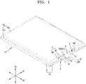
- FIG. 1 is a perspective view of a battery pack according to an embodiment of the disclosure.
- FIG. 2 is an exploded perspective view of the battery pack shown in FIG. 1 .
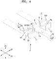
- FIGS. 3 and 4 are different perspective views illustrating a connection between a protection module package and a battery cell, shown in FIG. 1 .
- FIG. 5 is a perspective view of the protection module package shown in FIG. 1 .
- FIGS. 6 and 7 are different exploded perspective views of the protection module package shown in FIG. 1 .
- a battery pack may include a battery cell 10 including a terrace portion T from which electrodes 11 and 12 are drawn out, and a protection module package P electrically connected to the battery cell 10.
- the protection module package P may include an insulating frame F including a base portion Fb arranged on the terrace portion T of the battery cell 10 and a first partition wall W1 arranged on the base portion Fb to face the battery cell 10, a circuit portion C arranged on the insulating frame F, and an insulating block B surrounding at least a portion of the circuit portion C.
- the battery cell 10 may include an electrode assembly 10a, a casing 10b surrounding the electrode assembly 10a, and the electrodes 11 and 12 drawn out from the casing 10b.
- the electrode assembly 10a may be formed in a winding type in which first and second electrode plates and a separator between the first electrode plate and the second electrode plate are wound in a roll shape.
- the electrode assembly 10a may be formed in a stacked type in which the first and second electrode plates and the separator are stacked on each other.
- the first and second electrode plates of the electrode assembly 10a may be electrically connected to the outside of the casing 10b through the electrodes 11 and 12 of the battery cell 10.
- the electrodes 11 and 12 of the battery cell 10 may be electrically connected to the first and second electrode plates of the electrode assembly 10a, respectively, and may include a first electrode (i.e., the electrode 11) and a second electrode (i.e., the electrode 12), which have different polarities.
- the electrodes 11 and 12 of the battery cell 10 may be drawn out through the terrace portion T, and may be electrically connected to the protection module package P, as will be described later.
- the casing 10b may be formed to surround the electrode assembly 10a, and by sealing an excess portion of the casing 10b remaining after surrounding the electrode assembly 10a, a sealing portion TS for sealing the electrode assembly 10a may be formed.
- the battery cell 10 may include a body 10c including the electrode assembly 10a and the casing 10b surrounding the electrode assembly 10a, and a sealing portion TS formed as a part of the casing 10b along the periphery of the body 10c for sealing the electrode assembly 10a.
- the sealing portion TS may include the terrace portion T from which the electrodes 11 and 12 are drawn out, and may include, in addition to the terrace portion T, a side sealing portion S formed along the side of the body 10c of the battery cell 10.
- the protection module package P electrically connected to the battery cell 10 may be seated on the terrace portion T of the battery cell 10.
- the seating of the protection module package P on the terrace portion T of the battery cell 10 may mean that components forming the protection module package P, that is, the circuit portion C, the insulating frame F, and the insulating block B, are arranged on the terrace portion T of the battery cell 10.
- the electrodes 11 and 12 of the battery cell 10 may extend from the body 10c of the battery cell 10, and more specifically, the electrode assembly 10a forming the body 10c of the battery cell 10, and may be drawn out of the battery cell 10 through the terrace portion T.
- the electrodes 11 and 12 of the battery cell 10 drawn out of the battery cell 10 may be connected to a connection tab 50 of the circuit portion C.
- the circuit portion C may include a circuit board 60 having a conductive pattern forming a charge and discharge path connected to the battery cell 10.
- the circuit board 60 may provide a support base for the circuit portion C, for example, a support base for the connection tab 50 and a safety element D arranged on the circuit board 60.
- the circuit board 60 may provide a charge and discharge path from the connection tab 50 and the safety element D arranged on the circuit board 60 to an input/output line IO connected to the circuit board 60.
- the circuit portion C may be arranged on the insulating frame F. In this case, that the circuit portion C is arranged on the insulating frame F may mean that the circuit board 60 on which the safety element D and the connection tab 50 are arranged is arranged on the insulating frame F.
- connection tab 50 connected to the electrodes 11 and 12 of the battery cell 10 may be arranged on the circuit board 60.
- the connection tab 50 may be formed on at least one side of the safety element D along a first direction Z1.
- the first direction Z1 may correspond to a longitudinal direction of the terrace portion T, and may correspond to a longitudinal direction of the circuit board 60 arranged on the terrace portion T.
- the first direction Z1 may mean a direction in which the insulating frame F extends, and more specifically, a direction in which the base portion Fb and the first partition wall W1 of the insulating frame F extend.
- the first direction Z1 may correspond to a direction intersecting with a second direction Z2 in which the electrodes 11 and 12 of the battery cell 10 are drawn out from the terrace portion T.
- the first direction Z1 and the second direction Z2 may correspond to directions perpendicular to each other.
- connection tab 50 may include first and second connection tabs 501 and 502 formed on both sides of the safety element D in the first direction Z1, and the first and second connection tabs 501 and 502 may be electrically connected to the first and second electrodes 11 and 12 of the battery cell 10, respectively. More specifically, the connection tab 50 may be formed on both sides of the circuit board 60 with the safety element D as a center, the safety element D being formed at the central position of the circuit board 60 in the first direction Z1, and may include the first and second connection tabs 501 and 502 formed on both sides of the circuit board 60.
- the first and second connection tabs 501 and 502 may be connected to the first and second electrodes 11 and 12, respectively, while overlapping the first and second electrodes 11 and 12 of the battery cell 10 extending while surrounding the protection module package P.
- the first and second connection tabs 501 and 502 may be coupled to the first and second electrodes 11 and 12 of the battery cell 10 through welding or the like while overlapping the first and second electrodes 11 and 12 of the battery cell 10.
- the connection tab 50 may include a fixing piece 51 fixed on the circuit board 60 and a coupling piece 52 extending from the fixing piece 51 and connected to the electrodes 11 and 12 of the battery cell 10.
- the fixing piece 51 and the coupling piece 52 may overlap each other through a bending portion 55.
- the coupling piece 52 may be bent around the bending portion 55 to overlap the fixing piece 51 together with the electrodes 11 and 12 of the battery cell 10.
- the third direction Z3 may correspond to a direction intersecting with the first direction Z1 and the second direction Z2, and in an embodiment of the disclosure, the third direction Z3 may correspond to a direction perpendicular to the first direction Z1 and the second direction Z2.
- the third direction Z3 may refer to a height direction from a plane of the terrace portion T (refer to FIG. 2 ) formed by the first and second directions Z1 and Z2, a height direction from a plane of the circuit board 60 formed by the first and second directions Z1 and Z2, or a thickness direction of the circuit board 60.
- the safety element D may be arranged on the circuit board 60 together with the connection tab 50.
- the safety element D may be formed at a central position of the circuit board 60 in the first direction Z1.
- the safety element D may capture an abnormal state of the battery cell 10, such as overheating, overcharging, or overdischarging, and take a protective action.
- the circuit portion C may include a charge and discharge path connected to the first and second connection tabs 501 and 502, and may control charge and discharge current through the safety element D provided on the charge and discharge path connected selectively to the first connection tabs 501 among the first and second connection tabs 501 and 502.
- the safety element D may include a variable resistor having a resistance value that changes according to temperature, the variable resistor being arranged on the charge and discharge path to block the charge and discharge current when the battery cell 10 is overheated above a set temperature.
- the circuit portion C may include a charge and discharge path connected to the connection tab 50, and the charge and discharge path connected to the connection tab 50 may be connected to the outside of the battery pack through an external terminal of the input/output line lO.
- the outside of the battery pack may correspond to an external load receiving discharge power from the battery cell 10 or an external charger supplying charging power toward the battery cell 10.
- the input/output line IO may be electrically connected to the circuit board 60 through a connection region 60a of the circuit board 60 and may extend from the circuit board 60 in the second direction Z2.
- the circuit board 60 may extend in the first direction Z1, and the first direction Z1 may correspond to a longitudinal direction of the circuit board 60.
- the connection region 60a protruding in the second direction Z2 may be formed at a central position of the circuit board 60 in the first direction Z1, and the input/output line IO may be connected to the circuit board 60 through the connection region 60a of the circuit board 60.
- the circuit board 60 may extend in the first direction Z1 corresponding to the longitudinal direction of the circuit board 60 and be formed to have a substantially T-shape including the connection region 60a protruding in the second direction Z2.
- the circuit board 60 extending in the first and second directions Z1 and Z2 may be integrally formed.
- the connection region 60a of the circuit board 60 may be formed at a central position of the circuit board 60 in the first direction Z1, and may protrude in the second direction Z2 at a position adjacent to the safety element D formed at the central position of the circuit board 60.
- the safety element D may be covered with an insulating block B to be insulated and protected from external environment.
- the insulating block B may cover both the safety element D, arranged adjacently at a central position of the circuit board 60 in the first direction Z1, and the connection region 60a, and may insulate and protect, from the external environment, the safety element D and the connection region 60a to which the input/output line IO is connected.
- the insulating block B may include a portion covering the safety element D on the circuit board 60 while extending in the first direction Z1, and a portion covering the connection region 60a of the circuit board 60 while extending in the second direction Z2.
- the technical configuration of the insulating block (B) will be described later in more detail.
- the circuit board 60 may be arranged on the insulating frame F, and the input/output line IO may extend in the second direction Z2 from between the connection region 60a of the circuit board 60 and a protruding region Fa of the insulating frame F. More specifically, the input/output line IO may be coupled to a surface, which faces the protruding region Fa of the insulating frame F, of the connection region 60a of the circuit board 60, and thus may extend in the second direction Z2 from between the connection region 60a of the circuit board 60 and the protruding region Fa of the insulating frame F.
- the input/output line IO may extend in the second direction Z2 from the connection region 60a of the circuit board 60, and the insulating frame F may include a protruding region Fa that protrudes in the second direction Z2 to support the input/output line IO and extends parallel to the connection region 60a of the circuit board 60.
- the circuit portion C may be arranged on the insulating frame F.
- the circuit board 60 providing a support base of the circuit portion C may be arranged on the insulating frame F, and as the circuit board 60 in which the safety element D and the connection tab 50 are arranged is arranged on the insulating frame F, the insulating frame F may support the entire circuit portion C.
- the insulating frame F may be arranged on the terrace portion T (refer to FIG. 2 ) of the battery cell 10.
- the insulating frame F may extend in the first direction Z1 in parallel with the terrace portion T. More specifically, as the base portion Fb and the first partition wall W1 constituting the insulating frame F extend in parallel in the first direction Z1, the insulating frame F may generally extend in the first direction Z1.
- the circuit portion C may be arranged on the insulating frame F.
- the insulating frame F may be between the circuit portion C and the terrace portion T (refer to FIG. 2 ) of the battery cell 10 while supporting the circuit portion C.
- the insulating frame F may form a support base of the protection module package P, and may form the bottom of the protection module package P in contact with the terrace portion T. More specifically, the insulating frame F may form the bottom of the protection module package P in contact with the terrace portion T while extending in parallel in the first direction Z1, and may include the base portion Fb that provides insulation of the protection module package P (more specifically, the circuit portion C) from the terrace portion T.
- the base portion Fb may extend in parallel in the first direction Z1 between the circuit portion C or the circuit board 60 and the terrace portion T of the battery cell 10, and the base portion Fb and the circuit board 60 may be sequentially arranged in the third direction Z3 on the terrace portion T (refer to FIG. 2 ) of the battery cell 10.
- the base portion Fb may be formed to have a shape corresponding to the circuit board 60, and may have a substantially T-shape including a portion extending in the first direction Z1 and a protruding region Fa protruding in the second direction Z2 from a central position in the first direction Z1.
- the protruding region Fa may extend in parallel with the connection area 60a of the circuit board 60, and the input/output line IO may extend in the second direction Z2 from between the protruding region Fa and the connection region 60a extending parallel to each other.
- the insulating frame F may include the first partition wall W1 erected in the third direction Z3 to face the battery cell 10 (more specifically, the body 10c of the battery cell 10) on the base portion Fb arranged in the terrace portion T.
- the first partition wall W1 may be arranged to block the battery cell 10 between the circuit portion C and the battery cell 10, and thus may effectively block a contact between the circuit portion C and the battery cell 10 and provide insulation therebetween.
- the first partition wall W1 may block a contact between the connection tab 50 in the circuit portion C and the battery cell 10, and may provide insulation therebetween.
- the safety element D of the circuit portion C may be insulated by a separate insulating block B.
- connection tab 50 of the circuit portion C may be exposed to the outside of the protection module package P for connection with the electrodes 11 and 12 of the battery cell 10, insulation of the connection tab 50 may be provided through the first partition wall W1 between the connection tab 50 and the battery cell 10.
- An avoidance groove OP for avoiding physical interference with the insulating block B may be formed in the first partition wall W1.
- the first partition wall W1 may extend in the first direction Z1
- the avoidance groove OP for avoiding physical interference with the insulating block B surrounding the safety element D may be formed at a central position in which the safety element D is arranged in the first direction Z1.
- the avoidance groove OP may be formed to be opened upwardly from a central position of the first partition wall W1.
- the first partition wall W1 may extend in the first direction Z1 and may be arranged at a rear position of the insulating frame F in the second direction Z2 intersecting with the first direction Z1.
- the connection tab 50 may be arranged at a front position of the insulating frame F opposite to the first partition wall W1.
- that the connection tab 50 and the first partition wall W1 are respectively arranged at the front and rear positions of the insulating frame F may mean that the connection tab 50 and the first partition wall W1 are respectively arranged at the front and rear positions of the base portion Fb of the insulating frame F.
- that the connection tab 50 is arranged at the front position of the insulating frame F may mean that the bending portion 55 connecting the fixing piece 51 to the coupling piece 52 is arranged at the front position of the insulating frame F.
- the bending portion 55 or the coupling piece 52 extending from the bending portion 55 is arranged at a front position of the insulating frame F and the first partition wall W1 is arranged to block the battery cell 10 (more specifically, the body 10c of the battery cell 10) at a rear position of the insulating frame F, a contact between the coupling piece 52 and the battery cell 10 may be effectively blocked and insulation therebetween may be provided.
- the coupling piece 52 may be connected to the electrodes 11 and 12 of the battery cell 10 in a state of being erected in the third direction Z3 from the fixing piece 51 fixed to the circuit board 60. In this case, it may be said that the coupling piece 52 is arranged at a front position of the insulating frame F.
- the coupling piece 52 connected to the electrodes 11 and 12 of the battery cell 10 may be bent around the bending portion 55 to overlap the fixing piece 51 fixed to the circuit board 60.
- the bending portion 55 connecting the fixing piece 51 to the coupling piece 52 may be arranged at a front position of the insulating frame F.
- the first partition wall W1 may be formed at a rear position opposite to the front position of the insulating frame F in which the bending portion 55 of the connection tab 50 is formed, and thus, an avoidance space G may be formed between the first partition wall W1 and the coupling piece 52 extending from the bending portion 55, the first partition wall W1 and the coupling piece 52 being apart from each other in front and rear directions.
- the avoidance space G may prevent the first partition wall W1 from being damaged by welding between the electrodes 11 and 12 of the battery cell 10 and the coupling piece 52, which are arranged to overlap each other.
- the electrodes 11 and 12 of the battery cell 10 and the coupling piece 52 which are arranged to overlap each other, may be coupled to each other through laser welding, and the first partition wall W1 apart from the coupling piece 52 through the avoidance space G may not be damaged by the welding heat of the coupling piece 52.
- the electrodes 11 and 12 of the battery cell 10 and the coupling piece 52 may be arranged to overlap each other in a state of being erected in the third direction Z3 from the base portion Fb of the insulating frame F.
- the electrodes 11 and 12 of the battery cell 10 and the coupling piece 52 may be arranged in a state of being erected at a position in front of the insulating frame F, and may be welded to each other by a laser irradiated in a front-rear direction.
- the first partition wall W1 may be apart from the coupling piece 52 in a front position of the insulating frame F with the avoidance space G therebetween, and the welding heat transferred from the coupling piece 52 may be transferred to the avoidance space G and may not be transferred directly to the first partition wall W1.
- the electrodes 11 and 12 of the battery cell 10 and the coupling piece 52 which are coupled to each other in a state of being erected in the third direction Z3 from the insulating frame F (e.g., the base portion Fb of the insulating frame F), may overlap the circuit board 60 arranged on the base portion Fb while being bent toward the base portion Fb.
- the electrodes 11 and 12 of the battery cell 10 and the coupling piece 52, which are coupled to each other may be folded toward the fixing piece 51 fixed to the circuit board 60, and may overlap the fixing piece 51 of the circuit board 60.
- the electrodes 11 and 12 of the battery cell 10 and the coupling piece 52 which are coupled to each other, may overlap the fixing piece 51 and may be insulated from external environment through attachment of an insulating tape (not shown) while overlapping the fixing piece 51, and separation from the fixing piece 51 may be prevented.
- the insulating frame F may include a base portion Fb arranged on the terrace portion T, a first partition wall W1 erected in the third direction Z3 on the base portion Fb to face the battery cell 10, and a second partition wall W2 formed to surround the circuit portion C together with the first partition wall W1 on the base portion Fb.
- the base portion Fb and the first and second partition walls W1 and W2 may form an accommodation space for the circuit portion C while being connected to each other.
- the first and second partition walls W1 and W2 may surround the circuit portion C.
- the first and second partition walls W1 and W2 may open the front of the circuit portion C so as not to interfere with the electrodes 11 and 12 of the battery cell 10, which are drawn out from the battery cell 10 in the second direction Z2 and connected to the connection tab 50 through the front of the circuit portion C.
- the first and second partition walls W1 and W2 may be formed on the rear of the circuit portion C facing the battery cell 10 (i.e., the body 10c of the battery cell 10) and on the side connected to the rear of the circuit portion C, and thus may surround the rear and side of the circuit portion C.
- the circuit portion C may be protected and insulated from the external environment by providing the first and second partition walls W1 and W2 surrounding the rear and side of the circuit portion C.
- the first partition wall W1 may be arranged to block the battery cell 10 (i.e., the body 10c of the battery cell 10) at the rear of the circuit portion C, thereby providing electrical insulation between the circuit portion C and the battery cell 10.
- the casing 10b forming the outer surface of the battery cell 10 may include a metal thin film, and may insulate the circuit portion C from the battery cell 10 through the first partition wall W1 arranged to block the battery cell 10.
- the protection module package P may be formed to have a shorter length than the terrace portion T in the first direction Z1, and may be arranged at a central position of the terrace portion T apart from a side sealing portion S formed on both edges of the terrace portion T.
- the metal thin film of the casing 10b may be exposed to a cross-section of the side sealing portion S.
- the protection module package P according to an embodiment of the disclosure may be formed in the central position of the terrace portion T apart from both edges of the terrace portion T, in which the side sealing portion S is arranged, thereby blocking a contact and electrical interference with the side sealing portion S.
- the protection module package P may have a shorter length than the terrace portion T of the battery cell 10 in the first direction Z1, and thus may reduce physical and electrical interference with peripheral components such as the side sealing portion S and provide an extra mounting space for other configurations through an extra space on the terrace portion T.
- the second partition wall W2 may surround the side of the circuit portion C while extending in the second direction Z2 opposite to the battery cell 10 from both edges of the first partition wall W1 in the first direction Z1. That is, the second partition wall W2 may be formed in a pair on both edges of the first partition wall W1 to surround both sides of the circuit portion C facing each other in the first direction Z1.
- the second partition wall W2 may form an accommodation space of the circuit portion C together with the first partition wall W1 while extending in the second direction Z2 intersecting with the first direction Z1 from both edges of the first partition wall W1 extending in the first direction Z1, and may form the insulating frame F providing an accommodation space of the circuit portion C together with the base portion Fb by which the first and second partition walls W1 and W2 are supported,
- the insulating frame F may form an accommodation space for the circuit portion C while surrounding the lower side, rear, and side of the circuit portion C, and for connection with the electrodes 11 and 12 of the battery cell 10, may form an accommodation space opened toward the front and upper side of the circuit portion C.
- the input/output line IO may extend through the front of the circuit portion C, which is opened.
- the circuit portion C may include a circuit board 60, and a safety element D and a connection tab 50 arranged on the circuit board 60.
- the connection tab 50 may be formed in an exposed state for connection with the electrodes 11 and 12 of the battery cell 10, and may be exposed to the outside of the protection module package P to allow connection with the electrodes 11 and 12 of the battery cell 10.
- the safety element D may be protected from the external environment by being surrounded by the insulating block B, and may be insulated from the external environment.
- the insulating block B may be formed to surround the safety element D on the circuit board 60 on which the safety element D is arranged, and may entirely surround the entire outer surface except for the bottom of the safety element D connected to the circuit board 60.
- the insulating block B may be formed separately from the insulating frame F.
- the insulating block B may be formed on the insulating frame F, but may be formed on the circuit board 60 seated on the insulating frame F and be separated from the insulating frame F with the circuit board 60 therebetween.
- the insulating block B and the insulating frame F may each include an insulating resin material, and may include the same insulating resin material. However, the insulating block B may be formed on the circuit board 60 arranged on the insulating frame F and be separated from the insulating frame F. The insulating block B may cover the safety element D formed at a central position of the circuit board 60 in the first direction Z1, and the connection region 60a formed at a position adjacent to the safety element D, and thus may protect and insulate the safety element D and the connection region 60a from the external environment. More specifically, the insulating block B may include a portion covering the safety element D on the circuit board 60 while extending in the first direction Z1, and a portion covering the connection region 60a of the circuit board 60 while extending in the second direction Z2.
- the method of manufacturing a battery pack including the battery cell 10 including the terrace portion T from which the electrodes 11 and 12 are drawn out, the circuit portion C including the connection tab 50 connected to the electrodes 11 and 12 of the battery cell 10, and the insulating frame F including the base portion Fb arranged on the terrace portion T of the battery cell 10 and the first partition wall W1 arranged on the base portion Fb to face the battery cell 10 (more specifically, the body 10c of the battery cell 10), may include,
- connection tab 50 in a state in which the connection tab 50 is erected to face the first partition wall W1 with the avoidance space G between the connection tab 50 and the first partition wall W1, connecting the electrodes 11 and 12 of the battery cell 10 to the connection tab 50, and bending the connection tab 50 and the electrodes 11 and 12 of the battery cell 10, which are connected to each other, to be seated on the floor of the avoidance space G.
- connection tab 50 (more specifically, the coupling piece 52 of the connection tab 50) may be arranged at a front position of the insulating frame F in the second direction Z2 intersecting with the first direction Z1 in which the insulating frame F extends, and the first partition wall W1 may be arranged at a rear position of the insulating frame F. And, in a state in which the connection tab 50 arranged at the front position of the insulating frame F is erected in the third direction Z3, an avoidance space G may be formed between the connection tab 50 arranged at the front position of the insulating frame F and the first partition wall W1 arranged at the rear position of the insulating frame F.
- connection tab 50 and the first partition wall W1 are arranged at the front position and the rear position of the insulating frame F, respectively, may mean that the connection tab 50 and the first partition wall W1 are arranged at the front position and the rear position of the base portion Fb of the insulating frame F, respectively.
- an electrical connection between the battery cell 10 and the circuit portion C may be made by coupling the electrodes 11 and 12 of the battery cell 10 to the connection tab 50 of the circuit portion C by using welding or the like in a state in which the electrodes 11 and 12 of the battery cell 10 and the connection tab 50 of the circuit portion C are arranged to overlap each other. More specifically, the electrodes 11 and 12 of the battery cell 10 may extend through the bottom of the protection module package P, surround the protection module package P, and overlap the connection tab 50 arranged in front of the circuit portion C.
- connection tab 50 (i.e., the coupling piece 52 of the connection tab 50) may overlap the electrodes 11 and 12 of the battery cell 10 in a state of being erected in the third direction Z3, and the connection tab 50 and the electrodes 11 and 12 of the battery cell 10 may be coupled to each other through welding.
- the connection tab 50 and the electrodes 11 and 12 of the battery cell 10, which overlap each other at the front position of the insulating frame F, may be apart from the first partition wall W1, arranged at the rear position of the insulating frame F, with an avoidance space G therebetween, and thus, damage to the first partition wall W1 at the rear position, the damage being caused by welding performed at the front position of the insulating frame F, may be prevented.
- the electrodes 11 and 12 of the battery cell 10 and the connection tab 50 i.e., the coupling piece 52 of the connection tab 50
- the electrodes 11 and 12 of the battery cell 10 and the connection tab 50 may be arranged to face the first partition wall W1 while being erected in the direction Z3, and an avoidance space G may be formed between the electrodes 11 and 12 and connection tab 50 and the first partition wall W1, arranged to face each other, and thus, damage to the first partition wall W1 may be prevented.
- the electrodes 11 and 12 of the battery cell 10 and the connection tab 50, connected to each other may be bent together toward the bottom of the avoidance space G.
- the electrodes 11 and 12 of the battery cell 10 and the coupling piece 52 of the connection tab 50, connected to each other may overlap each other on the circuit board 60 forming the bottom of the avoidance space G.
- the electrodes 11 and 12 of the battery cell 10 and the coupling piece 52 of the connection tab 50, connected to each other may overlap the fixing piece 51 fixed to the circuit board 60 and may be insulated from external environment through attachment of an insulating tape (not shown) in a state in which they overlap the fixing piece 51, and separation from the fixing piece 51 may be prevented.
- a battery pack including a compact protection module package including a circuit portion electrically connected to a battery cell and providing insulation of the circuit portion, and a method of manufacturing the battery pack may be provided.
Landscapes
- Chemical & Material Sciences (AREA)
- Chemical Kinetics & Catalysis (AREA)
- Electrochemistry (AREA)
- General Chemical & Material Sciences (AREA)
- Engineering & Computer Science (AREA)
- Manufacturing & Machinery (AREA)
- Microelectronics & Electronic Packaging (AREA)
- Connection Of Batteries Or Terminals (AREA)
- Battery Mounting, Suspending (AREA)
Abstract
A battery pack and a method of manufacturing the battery pack are provided. The battery pack includes a battery cell including a terrace portion from which an electrode is drawn out, and a protection module package electrically connected to the battery cell, wherein the protection module package includes an insulating frame including a base portion arranged on the terrace portion of the battery cell and a first partition wall arranged on the base portion to face the battery cell, a circuit portion arranged on the insulating frame, and an insulating block surrounding at least a portion of the circuit portion. According to one or more embodiments, there are provided a battery pack including a circuit portion electrically connected to a battery cell and a compact protection module package that provides insulation of the circuit portion, and a method of manufacturing the battery pack.
Description
- One or more embodiments relate to a battery pack and a method of manufacturing the battery pack.
- In general, secondary batteries are batteries that can be charged and discharged, unlike primary batteries that cannot be charged. Secondary batteries are used as energy sources for mobile devices, electric vehicles, hybrid vehicles, electric bicycles, uninterruptible power supply, etc. Secondary batteries may be used in the form of a single battery or in the form of a module bundled as a unit by connecting a plurality of batteries, depending on the type of external device to be applied.
- One or more embodiments include a battery pack including a circuit portion electrically connected to a battery cell and a compact protection module package that provides insulation of the circuit portion, and a method of manufacturing the battery pack.
- Additional aspects will be set forth in part in the description which follows and, in part, will be apparent from the description, or may be learned by practice of the presented embodiments of the disclosure.
- According to one or more embodiments, a battery pack includes
- a battery cell including a terrace portion from which an electrode is drawn out, and
- a protection module package electrically connected to the battery cell,
- wherein the protection module package includes
- an insulating frame including a base portion arranged on the terrace portion of the battery cell and a first partition wall arranged on the base portion to face the battery cell,
- a circuit portion arranged on the insulating frame, and
- an insulating block surrounding at least a portion of the circuit portion.
- The base portion may be between the terrace portion and the circuit portion.
- The first partition wall may be between a body of the battery cell to which the electrode is connected and the circuit portion.
- The base portion, the first partition wall, and the terrace portion may extend in a first direction in parallel with one another, and
the electrode may be drawn out from the terrace portion in a second direction intersecting with the first direction. - The circuit portion may include
- a circuit board providing a support base for the circuit portion,
- a connection tab arranged on the circuit board and connected to the electrode of the battery cell, and
- a safety element arranged on the circuit board and connected to the connection tab.
- The safety element may be arranged at a central position of the circuit board in a first direction in which the circuit board extends, and
the connection tab may include first and second connection tabs arranged on both sides of the safety element. - The insulating block may surround the safety element.
- The insulating block may be separated from the insulating frame with the circuit board therebetween.
- The insulating block may surround an entire outer surface of the safety element except for a bottom of the safety element connected to the circuit board.
- The circuit board may include a connection region protruding in a second direction intersecting with a first direction in which the circuit board extends, and
- the battery pack may further include an input/output line connected to a connection region of the circuit board.
- The input/output line may extend between the connection region of the circuit board and the base portion.
- The connection region may protrude from a central position of the circuit board in the first direction in which the circuit board extends, and
the insulating block may surround both the safety element and the connection region. - A second partition wall surrounding the circuit portion may be formed on the base portion together with the first partition wall.
- The electrode of the battery cell may be connected to the circuit portion through the front of the circuit portion, and
the first and second partition walls may surround the rear and side of the circuit portion. - The first and second partition walls and the base portion may be connected to each other and surround the rear, side, and lower side of the circuit portion to form an accommodation space for the circuit portion.
- The first partition wall may extend in a first direction, and
the second partition wall may extend, in a second direction opposite to the battery cell, from both edges of the first partition wall in the first direction. - The circuit portion may include a connection tab connected to the electrode of the battery cell,
wherein the connection tab and the first partition wall may be respectively arranged at a front position and a rear position of the insulating frame in a second direction intersecting with a first direction in which the first partition wall extends. - An avoidance space may be formed between the connection tab and the first partition wall, which face each other while being erected in a third direction intersecting with the first and second directions.
- The connection tab may include
- a fixing piece fixed on a circuit board of the circuit portion,
- a coupling piece connected to the electrode of the battery cell, and
- a bending portion connecting the fixing piece to the coupling piece,
- wherein the bending portion may be arranged at a front position of the insulating frame.
- According to one or more embodiments, there is provided a method of manufacturing a battery pack,
- wherein the battery pack includes a battery cell including a terrace portion from which an electrode is drawn out, a circuit portion including a connection tab connected to the electrode of the battery cell, and an insulating frame including a base portion arranged on the terrace portion of the battery cell and a first partition wall arranged on the base portion to face the battery cell. The method includes:
- connecting the connection tab to the electrode of the battery cell in a state in which the connection tab is erected to face the first partition wall with an avoidance space between the connection tab and the first partition wall; and
- bending the connection tab and the electrode of the battery cell, connected to each other, to be seated on a floor of the avoidance space.
- The connection tab may include a fixing piece fixed on a circuit board of the circuit portion, a coupling piece connected to the electrode of the battery cell, and a bending portion connecting the fixing piece to the coupling piece, and
in the bending, the coupling piece connected to the electrode of the battery cell may be bent around the bending portion to overlap the fixing piece. - At least some of the above and other features of the invention are set out in the claims.
- The above and other aspects, features, and advantages of certain embodiments of the disclosure will be more apparent from the following description taken in conjunction with the accompanying drawings, in which:
-
FIG. 1 is a perspective view of a battery pack according to an embodiment of the disclosure; -
FIG. 2 is an exploded perspective view of the battery pack shown inFIG. 1 ; -
FIGS. 3 and4 are different perspective views illustrating a connection between a protection module package and a battery cell, shown inFIG. 1 ; -
FIG. 5 is a perspective view of the protection module package shown inFIG. 1 ; and -
FIGS. 6 and7 are different exploded perspective views of the protection module package shown inFIG. 1 . - Reference will now be made in detail to embodiments, examples of which are illustrated in the accompanying drawings, wherein like reference numerals refer to like elements throughout. In this regard, the present embodiments may have different forms and should not be construed as being limited to the descriptions set forth herein. Accordingly, the embodiments are merely described below, by referring to the figures, to explain aspects of the present description. As used herein, the term "and/or" includes any and all combinations of one or more of the associated listed items. Expressions such as "at least one of," when preceding a list of elements, modify the entire list of elements and do not modify the individual elements of the list.
- Hereinafter, a battery pack according to an embodiment of the disclosure will be described with reference to the accompanying drawings.
-
FIG. 1 is a perspective view of a battery pack according to an embodiment of the disclosure.FIG. 2 is an exploded perspective view of the battery pack shown inFIG. 1 .FIGS. 3 and4 are different perspective views illustrating a connection between a protection module package and a battery cell, shown inFIG. 1 .FIG. 5 is a perspective view of the protection module package shown inFIG. 1 .FIGS. 6 and7 are different exploded perspective views of the protection module package shown inFIG. 1 . - Referring to
FIGS. 1 and2 , a battery pack according to an embodiment of the disclosure may include abattery cell 10 including a terrace portion T from whichelectrodes battery cell 10. The protection module package P may include an insulating frame F including a base portion Fb arranged on the terrace portion T of thebattery cell 10 and a first partition wall W1 arranged on the base portion Fb to face thebattery cell 10, a circuit portion C arranged on the insulating frame F, and an insulating block B surrounding at least a portion of the circuit portion C. - The
battery cell 10 may include anelectrode assembly 10a, acasing 10b surrounding theelectrode assembly 10a, and theelectrodes casing 10b. Although not shown in the drawings, theelectrode assembly 10a may be formed in a winding type in which first and second electrode plates and a separator between the first electrode plate and the second electrode plate are wound in a roll shape. Alternatively, theelectrode assembly 10a may be formed in a stacked type in which the first and second electrode plates and the separator are stacked on each other. The first and second electrode plates of theelectrode assembly 10a may be electrically connected to the outside of thecasing 10b through theelectrodes battery cell 10. Theelectrodes battery cell 10 may be electrically connected to the first and second electrode plates of theelectrode assembly 10a, respectively, and may include a first electrode (i.e., the electrode 11) and a second electrode (i.e., the electrode 12), which have different polarities. Theelectrodes battery cell 10 may be drawn out through the terrace portion T, and may be electrically connected to the protection module package P, as will be described later. - The
casing 10b may be formed to surround theelectrode assembly 10a, and by sealing an excess portion of thecasing 10b remaining after surrounding theelectrode assembly 10a, a sealing portion TS for sealing theelectrode assembly 10a may be formed. In this case, thebattery cell 10 may include abody 10c including theelectrode assembly 10a and thecasing 10b surrounding theelectrode assembly 10a, and a sealing portion TS formed as a part of thecasing 10b along the periphery of thebody 10c for sealing theelectrode assembly 10a. In this case, the sealing portion TS may include the terrace portion T from which theelectrodes body 10c of thebattery cell 10. As will be described later, the protection module package P electrically connected to thebattery cell 10 may be seated on the terrace portion T of thebattery cell 10. In this case, the seating of the protection module package P on the terrace portion T of thebattery cell 10 may mean that components forming the protection module package P, that is, the circuit portion C, the insulating frame F, and the insulating block B, are arranged on the terrace portion T of thebattery cell 10. Theelectrodes battery cell 10 may extend from thebody 10c of thebattery cell 10, and more specifically, theelectrode assembly 10a forming thebody 10c of thebattery cell 10, and may be drawn out of thebattery cell 10 through the terrace portion T. In addition, theelectrodes battery cell 10 drawn out of thebattery cell 10 may be connected to aconnection tab 50 of the circuit portion C. - Referring to
FIGS. 3 to 7 , the circuit portion C may include acircuit board 60 having a conductive pattern forming a charge and discharge path connected to thebattery cell 10. Thecircuit board 60 may provide a support base for the circuit portion C, for example, a support base for theconnection tab 50 and a safety element D arranged on thecircuit board 60. In addition, thecircuit board 60 may provide a charge and discharge path from theconnection tab 50 and the safety element D arranged on thecircuit board 60 to an input/output line IO connected to thecircuit board 60. As will be described later, in an embodiment of the disclosure, the circuit portion C may be arranged on the insulating frame F. In this case, that the circuit portion C is arranged on the insulating frame F may mean that thecircuit board 60 on which the safety element D and theconnection tab 50 are arranged is arranged on the insulating frame F. - The
connection tab 50 connected to theelectrodes battery cell 10 may be arranged on thecircuit board 60. In an embodiment of the disclosure, theconnection tab 50 may be formed on at least one side of the safety element D along a first direction Z1. Throughout this specification, the first direction Z1 may correspond to a longitudinal direction of the terrace portion T, and may correspond to a longitudinal direction of thecircuit board 60 arranged on the terrace portion T. In an embodiment of the disclosure, the first direction Z1 may mean a direction in which the insulating frame F extends, and more specifically, a direction in which the base portion Fb and the first partition wall W1 of the insulating frame F extend. In an embodiment of the disclosure, the first direction Z1 may correspond to a direction intersecting with a second direction Z2 in which theelectrodes battery cell 10 are drawn out from the terrace portion T. In an embodiment of the disclosure, the first direction Z1 and the second direction Z2 may correspond to directions perpendicular to each other. - In an embodiment of the disclosure, the
connection tab 50 may include first andsecond connection tabs second connection tabs second electrodes battery cell 10, respectively. More specifically, theconnection tab 50 may be formed on both sides of thecircuit board 60 with the safety element D as a center, the safety element D being formed at the central position of thecircuit board 60 in the first direction Z1, and may include the first andsecond connection tabs circuit board 60. In an embodiment of the disclosure, the first andsecond connection tabs second electrodes second electrodes battery cell 10 extending while surrounding the protection module package P. In an embodiment of the disclosure, the first andsecond connection tabs second electrodes battery cell 10 through welding or the like while overlapping the first andsecond electrodes battery cell 10. - The
connection tab 50 may include a fixingpiece 51 fixed on thecircuit board 60 and acoupling piece 52 extending from the fixingpiece 51 and connected to theelectrodes battery cell 10. In an embodiment of the disclosure, the fixingpiece 51 and thecoupling piece 52 may overlap each other through a bendingportion 55. In addition, as will be described later, after thecoupling piece 52 is connected to theelectrodes battery cell 10 in a state of being erected in a third direction Z3 from the fixingpiece 51 through the bendingportion 55, thecoupling piece 52 may be bent around the bendingportion 55 to overlap the fixingpiece 51 together with theelectrodes battery cell 10. - Throughout this specification, the third direction Z3 may correspond to a direction intersecting with the first direction Z1 and the second direction Z2, and in an embodiment of the disclosure, the third direction Z3 may correspond to a direction perpendicular to the first direction Z1 and the second direction Z2. For example, the third direction Z3 may refer to a height direction from a plane of the terrace portion T (refer to
FIG. 2 ) formed by the first and second directions Z1 and Z2, a height direction from a plane of thecircuit board 60 formed by the first and second directions Z1 and Z2, or a thickness direction of thecircuit board 60. - The safety element D may be arranged on the
circuit board 60 together with theconnection tab 50. For example, the safety element D may be formed at a central position of thecircuit board 60 in the first direction Z1. The safety element D may capture an abnormal state of thebattery cell 10, such as overheating, overcharging, or overdischarging, and take a protective action. In an embodiment of the disclosure, the circuit portion C may include a charge and discharge path connected to the first andsecond connection tabs first connection tabs 501 among the first andsecond connection tabs battery cell 10 is overheated above a set temperature. - The circuit portion C may include a charge and discharge path connected to the
connection tab 50, and the charge and discharge path connected to theconnection tab 50 may be connected to the outside of the battery pack through an external terminal of the input/output line lO. In an embodiment of the disclosure, the outside of the battery pack may correspond to an external load receiving discharge power from thebattery cell 10 or an external charger supplying charging power toward thebattery cell 10. - The input/output line IO may be electrically connected to the
circuit board 60 through aconnection region 60a of thecircuit board 60 and may extend from thecircuit board 60 in the second direction Z2. In an embodiment of the disclosure, thecircuit board 60 may extend in the first direction Z1, and the first direction Z1 may correspond to a longitudinal direction of thecircuit board 60. Theconnection region 60a protruding in the second direction Z2 may be formed at a central position of thecircuit board 60 in the first direction Z1, and the input/output line IO may be connected to thecircuit board 60 through theconnection region 60a of thecircuit board 60. In an embodiment of the disclosure, thecircuit board 60 may extend in the first direction Z1 corresponding to the longitudinal direction of thecircuit board 60 and be formed to have a substantially T-shape including theconnection region 60a protruding in the second direction Z2. In addition, thecircuit board 60 extending in the first and second directions Z1 and Z2 may be integrally formed. - The
connection region 60a of thecircuit board 60 may be formed at a central position of thecircuit board 60 in the first direction Z1, and may protrude in the second direction Z2 at a position adjacent to the safety element D formed at the central position of thecircuit board 60. As will be described later, the safety element D may be covered with an insulating block B to be insulated and protected from external environment. The insulating block B may cover both the safety element D, arranged adjacently at a central position of thecircuit board 60 in the first direction Z1, and theconnection region 60a, and may insulate and protect, from the external environment, the safety element D and theconnection region 60a to which the input/output line IO is connected. To this end, the insulating block B may include a portion covering the safety element D on thecircuit board 60 while extending in the first direction Z1, and a portion covering theconnection region 60a of thecircuit board 60 while extending in the second direction Z2. The technical configuration of the insulating block (B) will be described later in more detail. - The
circuit board 60 may be arranged on the insulating frame F, and the input/output line IO may extend in the second direction Z2 from between theconnection region 60a of thecircuit board 60 and a protruding region Fa of the insulating frame F. More specifically, the input/output line IO may be coupled to a surface, which faces the protruding region Fa of the insulating frame F, of theconnection region 60a of thecircuit board 60, and thus may extend in the second direction Z2 from between theconnection region 60a of thecircuit board 60 and the protruding region Fa of the insulating frame F. In other words, the input/output line IO may extend in the second direction Z2 from theconnection region 60a of thecircuit board 60, and the insulating frame F may include a protruding region Fa that protrudes in the second direction Z2 to support the input/output line IO and extends parallel to theconnection region 60a of thecircuit board 60. - The circuit portion C may be arranged on the insulating frame F. In an embodiment of the disclosure, the
circuit board 60 providing a support base of the circuit portion C may be arranged on the insulating frame F, and as thecircuit board 60 in which the safety element D and theconnection tab 50 are arranged is arranged on the insulating frame F, the insulating frame F may support the entire circuit portion C. - The insulating frame F may be arranged on the terrace portion T (refer to
FIG. 2 ) of thebattery cell 10. In an embodiment of the disclosure, the insulating frame F may extend in the first direction Z1 in parallel with the terrace portion T. More specifically, as the base portion Fb and the first partition wall W1 constituting the insulating frame F extend in parallel in the first direction Z1, the insulating frame F may generally extend in the first direction Z1. - The circuit portion C may be arranged on the insulating frame F. In an embodiment of the disclosure, the insulating frame F may be between the circuit portion C and the terrace portion T (refer to
FIG. 2 ) of thebattery cell 10 while supporting the circuit portion C. In an embodiment of the disclosure, the insulating frame F may form a support base of the protection module package P, and may form the bottom of the protection module package P in contact with the terrace portion T. More specifically, the insulating frame F may form the bottom of the protection module package P in contact with the terrace portion T while extending in parallel in the first direction Z1, and may include the base portion Fb that provides insulation of the protection module package P (more specifically, the circuit portion C) from the terrace portion T. The base portion Fb may extend in parallel in the first direction Z1 between the circuit portion C or thecircuit board 60 and the terrace portion T of thebattery cell 10, and the base portion Fb and thecircuit board 60 may be sequentially arranged in the third direction Z3 on the terrace portion T (refer toFIG. 2 ) of thebattery cell 10. - In an embodiment of the disclosure, the base portion Fb may be formed to have a shape corresponding to the
circuit board 60, and may have a substantially T-shape including a portion extending in the first direction Z1 and a protruding region Fa protruding in the second direction Z2 from a central position in the first direction Z1. The protruding region Fa may extend in parallel with theconnection area 60a of thecircuit board 60, and the input/output line IO may extend in the second direction Z2 from between the protruding region Fa and theconnection region 60a extending parallel to each other. - The insulating frame F may include the first partition wall W1 erected in the third direction Z3 to face the battery cell 10 (more specifically, the
body 10c of the battery cell 10) on the base portion Fb arranged in the terrace portion T. The first partition wall W1 may be arranged to block thebattery cell 10 between the circuit portion C and thebattery cell 10, and thus may effectively block a contact between the circuit portion C and thebattery cell 10 and provide insulation therebetween. For example, the first partition wall W1 may block a contact between theconnection tab 50 in the circuit portion C and thebattery cell 10, and may provide insulation therebetween. As will be described later, the safety element D of the circuit portion C may be insulated by a separate insulating block B. In addition, because theconnection tab 50 of the circuit portion C may be exposed to the outside of the protection module package P for connection with theelectrodes battery cell 10, insulation of theconnection tab 50 may be provided through the first partition wall W1 between theconnection tab 50 and thebattery cell 10. An avoidance groove OP for avoiding physical interference with the insulating block B may be formed in the first partition wall W1. For example, the first partition wall W1 may extend in the first direction Z1, and the avoidance groove OP for avoiding physical interference with the insulating block B surrounding the safety element D may be formed at a central position in which the safety element D is arranged in the first direction Z1. The avoidance groove OP may be formed to be opened upwardly from a central position of the first partition wall W1. - The first partition wall W1 may extend in the first direction Z1 and may be arranged at a rear position of the insulating frame F in the second direction Z2 intersecting with the first direction Z1. In addition, the
connection tab 50 may be arranged at a front position of the insulating frame F opposite to the first partition wall W1. In this case, that theconnection tab 50 and the first partition wall W1 are respectively arranged at the front and rear positions of the insulating frame F may mean that theconnection tab 50 and the first partition wall W1 are respectively arranged at the front and rear positions of the base portion Fb of the insulating frame F. In this case, that theconnection tab 50 is arranged at the front position of the insulating frame F may mean that, in theconnection tab 50, rather than the fixingpiece 51 fixed to thecircuit board 60, thecoupling piece 52 arranged on the fixingpiece 51 and relatively vulnerable to insulation from the external environment is arranged at the front position of the insulating frame F. In addition, in an embodiment of the disclosure, that theconnection tab 50 is arranged at the front position of the insulating frame F may mean that the bendingportion 55 connecting the fixingpiece 51 to thecoupling piece 52 is arranged at the front position of the insulating frame F. - In an embodiment of the disclosure, as the bending
portion 55 or thecoupling piece 52 extending from the bendingportion 55 is arranged at a front position of the insulating frame F and the first partition wall W1 is arranged to block the battery cell 10 (more specifically, thebody 10c of the battery cell 10) at a rear position of the insulating frame F, a contact between thecoupling piece 52 and thebattery cell 10 may be effectively blocked and insulation therebetween may be provided. - Referring to
FIG. 4 , for the connection between thecoupling piece 52 and theelectrodes battery cell 10, thecoupling piece 52 may be connected to theelectrodes battery cell 10 in a state of being erected in the third direction Z3 from the fixingpiece 51 fixed to thecircuit board 60. In this case, it may be said that thecoupling piece 52 is arranged at a front position of the insulating frame F. Thecoupling piece 52 connected to theelectrodes battery cell 10 may be bent around the bendingportion 55 to overlap the fixingpiece 51 fixed to thecircuit board 60. In addition, in a state where the fixingpiece 51 and thecoupling piece 52 overlap each other, the bendingportion 55 connecting the fixingpiece 51 to thecoupling piece 52 may be arranged at a front position of the insulating frame F. - In an embodiment of the disclosure, the first partition wall W1 may be formed at a rear position opposite to the front position of the insulating frame F in which the bending
portion 55 of theconnection tab 50 is formed, and thus, an avoidance space G may be formed between the first partition wall W1 and thecoupling piece 52 extending from the bendingportion 55, the first partition wall W1 and thecoupling piece 52 being apart from each other in front and rear directions. The avoidance space G may prevent the first partition wall W1 from being damaged by welding between theelectrodes battery cell 10 and thecoupling piece 52, which are arranged to overlap each other. In an embodiment of the disclosure, theelectrodes battery cell 10 and thecoupling piece 52, which are arranged to overlap each other, may be coupled to each other through laser welding, and the first partition wall W1 apart from thecoupling piece 52 through the avoidance space G may not be damaged by the welding heat of thecoupling piece 52. - The
electrodes battery cell 10 and thecoupling piece 52 may be arranged to overlap each other in a state of being erected in the third direction Z3 from the base portion Fb of the insulating frame F. In addition, theelectrodes battery cell 10 and thecoupling piece 52 may be arranged in a state of being erected at a position in front of the insulating frame F, and may be welded to each other by a laser irradiated in a front-rear direction. In addition, as the first partition wall W1 is arranged in a state of being erected in the third direction Z3 at a rear position of the insulating frame F, the first partition wall W1 may be apart from thecoupling piece 52 in a front position of the insulating frame F with the avoidance space G therebetween, and the welding heat transferred from thecoupling piece 52 may be transferred to the avoidance space G and may not be transferred directly to the first partition wall W1. - In an embodiment of the disclosure, the
electrodes battery cell 10 and thecoupling piece 52, which are coupled to each other in a state of being erected in the third direction Z3 from the insulating frame F (e.g., the base portion Fb of the insulating frame F), may overlap thecircuit board 60 arranged on the base portion Fb while being bent toward the base portion Fb. For example, theelectrodes battery cell 10 and thecoupling piece 52, which are coupled to each other, may be folded toward the fixingpiece 51 fixed to thecircuit board 60, and may overlap the fixingpiece 51 of thecircuit board 60. In an embodiment of the disclosure, theelectrodes battery cell 10 and thecoupling piece 52, which are coupled to each other, may overlap the fixingpiece 51 and may be insulated from external environment through attachment of an insulating tape (not shown) while overlapping the fixingpiece 51, and separation from the fixingpiece 51 may be prevented. - Referring to
FIGS. 3 to 7 , in an embodiment of the disclosure, the insulating frame F may include a base portion Fb arranged on the terrace portion T, a first partition wall W1 erected in the third direction Z3 on the base portion Fb to face thebattery cell 10, and a second partition wall W2 formed to surround the circuit portion C together with the first partition wall W1 on the base portion Fb. The base portion Fb and the first and second partition walls W1 and W2 may form an accommodation space for the circuit portion C while being connected to each other. - In an embodiment of the disclosure, the first and second partition walls W1 and W2 may surround the circuit portion C. For example, the first and second partition walls W1 and W2 may open the front of the circuit portion C so as not to interfere with the
electrodes battery cell 10, which are drawn out from thebattery cell 10 in the second direction Z2 and connected to theconnection tab 50 through the front of the circuit portion C. However, the first and second partition walls W1 and W2 may be formed on the rear of the circuit portion C facing the battery cell 10 (i.e., thebody 10c of the battery cell 10) and on the side connected to the rear of the circuit portion C, and thus may surround the rear and side of the circuit portion C. In an embodiment of the disclosure, although the front of the circuit portion C is opened for connection with theelectrodes battery cell 10, the circuit portion C may be protected and insulated from the external environment by providing the first and second partition walls W1 and W2 surrounding the rear and side of the circuit portion C. - Referring to
FIG. 1 , the first partition wall W1 may be arranged to block the battery cell 10 (i.e., thebody 10c of the battery cell 10) at the rear of the circuit portion C, thereby providing electrical insulation between the circuit portion C and thebattery cell 10. In an embodiment of the disclosure, thecasing 10b forming the outer surface of thebattery cell 10 may include a metal thin film, and may insulate the circuit portion C from thebattery cell 10 through the first partition wall W1 arranged to block thebattery cell 10. - In an embodiment of the disclosure, the protection module package P may be formed to have a shorter length than the terrace portion T in the first direction Z1, and may be arranged at a central position of the terrace portion T apart from a side sealing portion S formed on both edges of the terrace portion T. The metal thin film of the
casing 10b may be exposed to a cross-section of the side sealing portion S. The protection module package P according to an embodiment of the disclosure may be formed in the central position of the terrace portion T apart from both edges of the terrace portion T, in which the side sealing portion S is arranged, thereby blocking a contact and electrical interference with the side sealing portion S. As the protection module package P according to an embodiment of the disclosure is formed to have a compact configuration, the protection module package P may have a shorter length than the terrace portion T of thebattery cell 10 in the first direction Z1, and thus may reduce physical and electrical interference with peripheral components such as the side sealing portion S and provide an extra mounting space for other configurations through an extra space on the terrace portion T. - Referring to
FIGS. 3 to 7 , in an embodiment of the disclosure, the second partition wall W2 may surround the side of the circuit portion C while extending in the second direction Z2 opposite to thebattery cell 10 from both edges of the first partition wall W1 in the first direction Z1. That is, the second partition wall W2 may be formed in a pair on both edges of the first partition wall W1 to surround both sides of the circuit portion C facing each other in the first direction Z1. In an embodiment of the disclosure, the second partition wall W2 may form an accommodation space of the circuit portion C together with the first partition wall W1 while extending in the second direction Z2 intersecting with the first direction Z1 from both edges of the first partition wall W1 extending in the first direction Z1, and may form the insulating frame F providing an accommodation space of the circuit portion C together with the base portion Fb by which the first and second partition walls W1 and W2 are supported, The insulating frame F may form an accommodation space for the circuit portion C while surrounding the lower side, rear, and side of the circuit portion C, and for connection with theelectrodes battery cell 10, may form an accommodation space opened toward the front and upper side of the circuit portion C. In addition, the input/output line IO may extend through the front of the circuit portion C, which is opened. - The circuit portion C may include a
circuit board 60, and a safety element D and aconnection tab 50 arranged on thecircuit board 60. Theconnection tab 50 may be formed in an exposed state for connection with theelectrodes battery cell 10, and may be exposed to the outside of the protection module package P to allow connection with theelectrodes battery cell 10. - The safety element D may be protected from the external environment by being surrounded by the insulating block B, and may be insulated from the external environment. For example, the insulating block B may be formed to surround the safety element D on the
circuit board 60 on which the safety element D is arranged, and may entirely surround the entire outer surface except for the bottom of the safety element D connected to thecircuit board 60. The insulating block B may be formed separately from the insulating frame F. For example, the insulating block B may be formed on the insulating frame F, but may be formed on thecircuit board 60 seated on the insulating frame F and be separated from the insulating frame F with thecircuit board 60 therebetween. The insulating block B and the insulating frame F may each include an insulating resin material, and may include the same insulating resin material. However, the insulating block B may be formed on thecircuit board 60 arranged on the insulating frame F and be separated from the insulating frame F. The insulating block B may cover the safety element D formed at a central position of thecircuit board 60 in the first direction Z1, and theconnection region 60a formed at a position adjacent to the safety element D, and thus may protect and insulate the safety element D and theconnection region 60a from the external environment. More specifically, the insulating block B may include a portion covering the safety element D on thecircuit board 60 while extending in the first direction Z1, and a portion covering theconnection region 60a of thecircuit board 60 while extending in the second direction Z2. - Hereinafter, a method of manufacturing a battery pack, according to an embodiment of the disclosure, will be described with reference to
FIGS. 2 and4 . - The method of manufacturing a battery pack, according to an embodiment of the disclosure, the battery pack including the
battery cell 10 including the terrace portion T from which theelectrodes connection tab 50 connected to theelectrodes battery cell 10, and the insulating frame F including the base portion Fb arranged on the terrace portion T of thebattery cell 10 and the first partition wall W1 arranged on the base portion Fb to face the battery cell 10 (more specifically, thebody 10c of the battery cell 10), may include, - in a state in which the
connection tab 50 is erected to face the first partition wall W1 with the avoidance space G between theconnection tab 50 and the first partition wall W1, connecting theelectrodes battery cell 10 to theconnection tab 50, and bending theconnection tab 50 and theelectrodes battery cell 10, which are connected to each other, to be seated on the floor of the avoidance space G. - In an embodiment of the disclosure, the connection tab 50 (more specifically, the
coupling piece 52 of the connection tab 50) may be arranged at a front position of the insulating frame F in the second direction Z2 intersecting with the first direction Z1 in which the insulating frame F extends, and the first partition wall W1 may be arranged at a rear position of the insulating frame F. And, in a state in which theconnection tab 50 arranged at the front position of the insulating frame F is erected in the third direction Z3, an avoidance space G may be formed between theconnection tab 50 arranged at the front position of the insulating frame F and the first partition wall W1 arranged at the rear position of the insulating frame F. In this case, that theconnection tab 50 is arranged at the front position of the insulating frame F may mean that thecoupling piece 52 of theconnection tab 50 is arranged at the front position, and may mean that thecoupling piece 52 or the bendingportion 55 from which thecoupling piece 52 extends is arranged at the front position. In addition, that theconnection tab 50 and the first partition wall W1 are arranged at the front position and the rear position of the insulating frame F, respectively, may mean that theconnection tab 50 and the first partition wall W1 are arranged at the front position and the rear position of the base portion Fb of the insulating frame F, respectively. - In an embodiment of the disclosure, an electrical connection between the
battery cell 10 and the circuit portion C may be made by coupling theelectrodes battery cell 10 to theconnection tab 50 of the circuit portion C by using welding or the like in a state in which theelectrodes battery cell 10 and theconnection tab 50 of the circuit portion C are arranged to overlap each other. More specifically, theelectrodes battery cell 10 may extend through the bottom of the protection module package P, surround the protection module package P, and overlap theconnection tab 50 arranged in front of the circuit portion C. In this case, the connection tab 50 (i.e., thecoupling piece 52 of the connection tab 50) may overlap theelectrodes battery cell 10 in a state of being erected in the third direction Z3, and theconnection tab 50 and theelectrodes battery cell 10 may be coupled to each other through welding. In this case, theconnection tab 50 and theelectrodes battery cell 10, which overlap each other at the front position of the insulating frame F, may be apart from the first partition wall W1, arranged at the rear position of the insulating frame F, with an avoidance space G therebetween, and thus, damage to the first partition wall W1 at the rear position, the damage being caused by welding performed at the front position of the insulating frame F, may be prevented. That is, in the connection between thebattery cell 10 and the circuit portion C, theelectrodes battery cell 10 and the connection tab 50 (i.e., thecoupling piece 52 of the connection tab 50), which overlap each other, may be arranged to face the first partition wall W1 while being erected in the direction Z3, and an avoidance space G may be formed between theelectrodes connection tab 50 and the first partition wall W1, arranged to face each other, and thus, damage to the first partition wall W1 may be prevented. In addition, theelectrodes battery cell 10 and theconnection tab 50, connected to each other, may be bent together toward the bottom of the avoidance space G. For example, theelectrodes battery cell 10 and thecoupling piece 52 of theconnection tab 50, connected to each other, may overlap each other on thecircuit board 60 forming the bottom of the avoidance space G. In an embodiment of the disclosure, theelectrodes battery cell 10 and thecoupling piece 52 of theconnection tab 50, connected to each other, may overlap the fixingpiece 51 fixed to thecircuit board 60 and may be insulated from external environment through attachment of an insulating tape (not shown) in a state in which they overlap the fixingpiece 51, and separation from the fixingpiece 51 may be prevented. - According to the disclosure, a battery pack including a compact protection module package including a circuit portion electrically connected to a battery cell and providing insulation of the circuit portion, and a method of manufacturing the battery pack may be provided.
- It should be understood that embodiments described herein should be considered in a descriptive sense only and not for purposes of limitation. Descriptions of features or aspects within each embodiment should typically be considered as available for other similar features or aspects in other embodiments. While one or more embodiments have been described with reference to the figures, it will be understood by those of ordinary skill in the art that various changes in form and details may be made therein without departing from the scope of the disclosure as defined by the following claims.
Claims (17)
- A battery pack comprising:a battery cell including a terrace portion from which an electrode is drawn out; anda protection module package electrically connected to the battery cell,wherein the protection module package includes:an insulating frame including a base portion arranged on the terrace portion of the battery cell and a first partition wall arranged on the base portion to face the battery cell;a circuit portion arranged on the insulating frame; andan insulating block surrounding at least a portion of the circuit portion.
- The battery pack of claim 1, wherein the base portion is between the terrace portion and the circuit portion.
- The battery pack of claim 1 or claim 2, wherein the first partition wall is between a body of the battery cell to which the electrode is connected and the circuit portion.
- The battery pack of any one of claims 1 to 3, whereinthe base portion, the first partition wall, and the terrace portion extend in a first direction in parallel with one another, andthe electrode is drawn out from the terrace portion in a second direction intersecting with the first direction.
- The battery pack of any one of claims 1 to 4, wherein the circuit portion includes:a circuit board providing a support base for the circuit portion;a connection tab arranged on the circuit board and connected to the electrode of the battery cell; anda safety element arranged on the circuit board and connected to the connection tab.
- The battery pack of claim 5, whereinthe safety element is arranged at a central position of the circuit board in a first direction in which the circuit board extends, andthe connection tab includes first and second connection tabs arranged on both sides of the safety element.
- The battery pack of claim 5 or claim 6, wherein the insulating block surrounds the safety element.
- The battery pack of claim 7, wherein:(i) the insulating block is separated from the insulating frame with the circuit board therebetween; and/or(ii) the insulating block surrounds an entire outer surface of the safety element except for a bottom of the safety element connected to the circuit board.
- The battery pack of any one of claims 5 to 8, whereinthe circuit board includes a connection region protruding in a second direction intersecting with a first direction in which the circuit board extends,the battery pack further comprising an input/output line connected to a connection region of the circuit board.
- The battery pack of claim 9, wherein:(i) the input/output line extends between the connection region of the circuit board and the base portion; and/or(ii) the connection region protrudes from a central position of the circuit board in the first direction in which the circuit board extends, andthe insulating block surrounds both the safety element and the connection region.
- The battery pack of any one of claims 1 to 10, wherein a second partition wall surrounding the circuit portion is formed on the base portion together with the first partition wall.
- The battery pack of claim 11, whereinthe electrode of the battery cell is connected to the circuit portion through the front of the circuit portion, andthe first and second partition walls surround the rear and side of the circuit portion, optionally wherein:
the first and second partition walls and the base portion are connected to each other and surround the rear, side, and lower side of the circuit portion to form an accommodation space for the circuit portion. - The battery pack of claim 11 or claim 12, whereinthe first partition wall extends in a first direction, andthe second partition wall extends, in a second direction opposite to the battery cell, from both edges of the first partition wall in the first direction.
- The battery pack of claim 1, whereinthe circuit portion includes a connection tab connected to the electrode of the battery cell,wherein the connection tab and the first partition wall are respectively arranged at a front position and a rear position of the insulating frame in a second direction intersecting with a first direction in which the first partition wall extends.
- The battery pack of claim 14, wherein:(i) an avoidance space is formed between the connection tab and the first partition wall, which face each other while being erected in a third direction intersecting with the first and second directions; and/or(ii) the connection tab includes:a fixing piece fixed on a circuit board of the circuit portion;a coupling piece connected to the electrode of the battery cell; anda bending portion connecting the fixing piece to the coupling piece,wherein the bending portion is arranged at a front position of the insulating frame.
- A method of manufacturing a battery pack including a battery cell including a terrace portion from which an electrode is drawn out, a circuit portion including a connection tab connected to the electrode of the battery cell, and an insulating frame including a base portion arranged on the terrace portion of the battery cell and a first partition wall arranged on the base portion to face the battery cell, the method comprising:connecting the connection tab to the electrode of the battery cell in a state in which the connection tab is erected to face the first partition wall with an avoidance space between the connection tab and the first partition wall; andbending the connection tab and the electrode of the battery cell, connected to each other, to be seated on a floor of the avoidance space.
- The method of claim 16, whereinthe connection tab includes a fixing piece fixed on a circuit board of the circuit portion, a coupling piece connected to the electrode of the battery cell, and a bending portion connecting the fixing piece to the coupling piece, andin the bending, the coupling piece connected to the electrode of the battery cell is bent around the bending portion to overlap the fixing piece.
Applications Claiming Priority (1)
| Application Number | Priority Date | Filing Date | Title |
|---|---|---|---|
| KR1020210019357A KR102514511B1 (en) | 2021-02-10 | 2021-02-10 | Battery pack and manufacturing method of the same |
Publications (1)
| Publication Number | Publication Date |
|---|---|
| EP4044321A1 true EP4044321A1 (en) | 2022-08-17 |
Family
ID=80446670
Family Applications (1)
| Application Number | Title | Priority Date | Filing Date |
|---|---|---|---|
| EP22156111.1A Pending EP4044321A1 (en) | 2021-02-10 | 2022-02-10 | Battery pack and method of manufacturing the same |
Country Status (3)
| Country | Link |
|---|---|
| US (1) | US12237541B2 (en) |
| EP (1) | EP4044321A1 (en) |
| KR (1) | KR102514511B1 (en) |
Cited By (1)
| Publication number | Priority date | Publication date | Assignee | Title |
|---|---|---|---|---|
| EP4498476A1 (en) * | 2023-07-21 | 2025-01-29 | Samsung Sdi Co., Ltd. | Battery pack |
Families Citing this family (3)
| Publication number | Priority date | Publication date | Assignee | Title |
|---|---|---|---|---|
| US12609418B2 (en) * | 2022-12-21 | 2026-04-21 | Meta Platforms Technologies, Llc | Metal can battery with stepped enclosure |
| KR102902878B1 (en) * | 2023-07-21 | 2025-12-22 | 주식회사 카펙발레오 | Battery moudle |
| KR102861483B1 (en) * | 2023-07-21 | 2025-09-18 | 주식회사 카펙발레오 | Battery moudle |
Citations (5)
| Publication number | Priority date | Publication date | Assignee | Title |
|---|---|---|---|---|
| EP1995804A1 (en) * | 2007-05-25 | 2008-11-26 | Samsung SDI Co., Ltd. | Battery pack |
| EP2273588A1 (en) * | 2009-07-06 | 2011-01-12 | Samsung SDI Co., Ltd. | Battery pack and manufacturing method for the same |
| KR20150038914A (en) * | 2013-10-01 | 2015-04-09 | 주식회사 엘지화학 | Battery Pack Having Hook Type PCM Case |
| EP3531495A1 (en) * | 2017-05-04 | 2019-08-28 | LG Chem, Ltd. | Battery pack and manufacturing method therefor |
| EP3686951A1 (en) * | 2018-06-29 | 2020-07-29 | Lg Chem, Ltd. | Secondary battery pack having holder |
Family Cites Families (9)
| Publication number | Priority date | Publication date | Assignee | Title |
|---|---|---|---|---|
| JP5005246B2 (en) | 2006-04-07 | 2012-08-22 | パナソニック株式会社 | Battery pack and manufacturing method thereof |
| US9350001B2 (en) | 2010-07-09 | 2016-05-24 | Samsung Sdi Co., Ltd. | Battery pack for a lithium polymer Battery |
| KR101539691B1 (en) * | 2012-10-19 | 2015-07-27 | 주식회사 엘지화학 | Frame for pouch type secondary battery, battery pack having the same and manufacturing method thereof |
| KR20140115756A (en) | 2013-03-22 | 2014-10-01 | 삼성에스디아이 주식회사 | Protection apparatus of battery pack and method for manufacturing the same and battery pack having the same |
| CN105324871B (en) * | 2013-07-01 | 2018-09-11 | Itm半导体有限公司 | Battery protection circuit module packaging, battery pack and electronic device with the battery pack |
| KR102256293B1 (en) * | 2014-07-28 | 2021-05-26 | 삼성에스디아이 주식회사 | Battery pack |
| KR20160039790A (en) | 2014-10-02 | 2016-04-12 | 주식회사 아이티엠반도체 | Battery protection circuits package |
| KR20160024892A (en) | 2016-02-15 | 2016-03-07 | 주식회사 엘지화학 | Battery Pack Having Fixing Part for PCM |
| KR102017674B1 (en) | 2017-10-11 | 2019-09-04 | 주식회사 아이티엠반도체 | Battery protection package and methods of fabricating the same |
-
2021
- 2021-02-10 KR KR1020210019357A patent/KR102514511B1/en active Active
-
2022
- 2022-02-09 US US17/667,967 patent/US12237541B2/en active Active
- 2022-02-10 EP EP22156111.1A patent/EP4044321A1/en active Pending
Patent Citations (5)
| Publication number | Priority date | Publication date | Assignee | Title |
|---|---|---|---|---|
| EP1995804A1 (en) * | 2007-05-25 | 2008-11-26 | Samsung SDI Co., Ltd. | Battery pack |
| EP2273588A1 (en) * | 2009-07-06 | 2011-01-12 | Samsung SDI Co., Ltd. | Battery pack and manufacturing method for the same |
| KR20150038914A (en) * | 2013-10-01 | 2015-04-09 | 주식회사 엘지화학 | Battery Pack Having Hook Type PCM Case |
| EP3531495A1 (en) * | 2017-05-04 | 2019-08-28 | LG Chem, Ltd. | Battery pack and manufacturing method therefor |
| EP3686951A1 (en) * | 2018-06-29 | 2020-07-29 | Lg Chem, Ltd. | Secondary battery pack having holder |
Cited By (1)
| Publication number | Priority date | Publication date | Assignee | Title |
|---|---|---|---|---|
| EP4498476A1 (en) * | 2023-07-21 | 2025-01-29 | Samsung Sdi Co., Ltd. | Battery pack |
Also Published As
| Publication number | Publication date |
|---|---|
| US20220255196A1 (en) | 2022-08-11 |
| US12237541B2 (en) | 2025-02-25 |
| KR20220115394A (en) | 2022-08-17 |
| KR102514511B1 (en) | 2023-03-27 |
Similar Documents
| Publication | Publication Date | Title |
|---|---|---|
| US12237541B2 (en) | Battery pack and method of manufacturing the same | |
| EP2357685B1 (en) | Rechargeable battery | |
| US9673437B2 (en) | Battery pack | |
| US11233279B2 (en) | Battery pack | |
| EP3723184B1 (en) | Battery pack | |
| CN111295794B (en) | Battery | |
| EP2905824B1 (en) | Battery pack | |
| US20110250473A1 (en) | Secondary battery pack | |
| WO2008035873A1 (en) | Battery module interface | |
| US20130089759A1 (en) | Rechargeable battery | |
| KR101885908B1 (en) | Rechargeable battery pack | |
| KR20170032098A (en) | Battery module and protecting structure applied for the same | |
| KR101985762B1 (en) | RECHARGEABLE BATTERY With Improved Connection Structure of Terminal AND BATTERY MODULE Comprising the Same | |
| US20240291051A1 (en) | Battery pack | |
| KR20130053000A (en) | Rechargeable battery pack | |
| KR20160144325A (en) | Electrode lead and secondary battery including the same | |
| WO2016039503A1 (en) | Secondary battery provided with overcurrent blocking means | |
| KR102124626B1 (en) | Secondary battery | |
| KR100346378B1 (en) | Lithium polymer battery pack | |
| EP4207431A1 (en) | Battery pack connector | |
| KR20210090888A (en) | Pouch type battery pack with folding structure and manufacturing method thereof | |
| EP4496090A2 (en) | Battery pack | |
| KR102426252B1 (en) | Battery pack | |
| KR20250022427A (en) | Battery module and battery pack including the same | |
| KR20250179260A (en) | Battery cell assembly |
Legal Events
| Date | Code | Title | Description |
|---|---|---|---|
| PUAI | Public reference made under article 153(3) epc to a published international application that has entered the european phase |
Free format text: ORIGINAL CODE: 0009012 |
|
| STAA | Information on the status of an ep patent application or granted ep patent |
Free format text: STATUS: REQUEST FOR EXAMINATION WAS MADE |
|
| 17P | Request for examination filed |
Effective date: 20220210 |
|
| AK | Designated contracting states |
Kind code of ref document: A1 Designated state(s): AL AT BE BG CH CY CZ DE DK EE ES FI FR GB GR HR HU IE IS IT LI LT LU LV MC MK MT NL NO PL PT RO RS SE SI SK SM TR |
|
| STAA | Information on the status of an ep patent application or granted ep patent |
Free format text: STATUS: EXAMINATION IS IN PROGRESS |
|
| 17Q | First examination report despatched |
Effective date: 20250103 |