EP4044285A1 - Negative electrode material, preparation method therefor and application thereof, and lithium-ion battery - Google Patents
Negative electrode material, preparation method therefor and application thereof, and lithium-ion battery Download PDFInfo
- Publication number
- EP4044285A1 EP4044285A1 EP20874397.1A EP20874397A EP4044285A1 EP 4044285 A1 EP4044285 A1 EP 4044285A1 EP 20874397 A EP20874397 A EP 20874397A EP 4044285 A1 EP4044285 A1 EP 4044285A1
- Authority
- EP
- European Patent Office
- Prior art keywords
- silicon
- lithium
- negative electrode
- electrode material
- organic
- Prior art date
- Legal status (The legal status is an assumption and is not a legal conclusion. Google has not performed a legal analysis and makes no representation as to the accuracy of the status listed.)
- Pending
Links
- 239000007773 negative electrode material Substances 0.000 title claims abstract description 194
- 229910001416 lithium ion Inorganic materials 0.000 title claims abstract description 62
- HBBGRARXTFLTSG-UHFFFAOYSA-N Lithium ion Chemical compound [Li+] HBBGRARXTFLTSG-UHFFFAOYSA-N 0.000 title claims abstract description 61
- 238000002360 preparation method Methods 0.000 title abstract description 9
- OKTJSMMVPCPJKN-UHFFFAOYSA-N Carbon Chemical compound [C] OKTJSMMVPCPJKN-UHFFFAOYSA-N 0.000 claims abstract description 140
- XUIMIQQOPSSXEZ-UHFFFAOYSA-N Silicon Chemical compound [Si] XUIMIQQOPSSXEZ-UHFFFAOYSA-N 0.000 claims abstract description 113
- 229910052799 carbon Inorganic materials 0.000 claims abstract description 104
- 229910052710 silicon Inorganic materials 0.000 claims abstract description 102
- 239000010703 silicon Substances 0.000 claims abstract description 101
- 239000000463 material Substances 0.000 claims abstract description 100
- 229910003002 lithium salt Inorganic materials 0.000 claims abstract description 42
- 159000000002 lithium salts Chemical class 0.000 claims abstract description 42
- 238000002156 mixing Methods 0.000 claims abstract description 30
- 239000011258 core-shell material Substances 0.000 claims abstract description 25
- 238000001354 calcination Methods 0.000 claims abstract description 20
- 239000000203 mixture Substances 0.000 claims abstract description 19
- 238000009777 vacuum freeze-drying Methods 0.000 claims abstract description 19
- WHXSMMKQMYFTQS-UHFFFAOYSA-N Lithium Chemical compound [Li] WHXSMMKQMYFTQS-UHFFFAOYSA-N 0.000 claims description 163
- 229910052744 lithium Inorganic materials 0.000 claims description 163
- ZMXDDKWLCZADIW-UHFFFAOYSA-N N,N-Dimethylformamide Chemical compound CN(C)C=O ZMXDDKWLCZADIW-UHFFFAOYSA-N 0.000 claims description 54
- 229910002804 graphite Inorganic materials 0.000 claims description 39
- 239000010439 graphite Substances 0.000 claims description 39
- 238000003756 stirring Methods 0.000 claims description 38
- 238000000034 method Methods 0.000 claims description 37
- 238000010438 heat treatment Methods 0.000 claims description 36
- 239000007787 solid Substances 0.000 claims description 29
- OAICVXFJPJFONN-UHFFFAOYSA-N Phosphorus Chemical compound [P] OAICVXFJPJFONN-UHFFFAOYSA-N 0.000 claims description 28
- 229910052698 phosphorus Inorganic materials 0.000 claims description 28
- 239000011574 phosphorus Substances 0.000 claims description 28
- 239000002245 particle Substances 0.000 claims description 26
- 239000011295 pitch Substances 0.000 claims description 22
- 229920000058 polyacrylate Polymers 0.000 claims description 22
- 239000011301 petroleum pitch Substances 0.000 claims description 19
- CSDREXVUYHZDNP-UHFFFAOYSA-N alumanylidynesilicon Chemical compound [Al].[Si] CSDREXVUYHZDNP-UHFFFAOYSA-N 0.000 claims description 15
- 229910045601 alloy Inorganic materials 0.000 claims description 14
- 239000000956 alloy Substances 0.000 claims description 14
- 239000001768 carboxy methyl cellulose Substances 0.000 claims description 13
- 229910000838 Al alloy Inorganic materials 0.000 claims description 11
- 239000011247 coating layer Substances 0.000 claims description 11
- 239000002904 solvent Substances 0.000 claims description 11
- 239000003792 electrolyte Substances 0.000 claims description 10
- FHVDTGUDJYJELY-UHFFFAOYSA-N 6-{[2-carboxy-4,5-dihydroxy-6-(phosphanyloxy)oxan-3-yl]oxy}-4,5-dihydroxy-3-phosphanyloxane-2-carboxylic acid Chemical compound O1C(C(O)=O)C(P)C(O)C(O)C1OC1C(C(O)=O)OC(OP)C(O)C1O FHVDTGUDJYJELY-UHFFFAOYSA-N 0.000 claims description 9
- 229920002134 Carboxymethyl cellulose Polymers 0.000 claims description 9
- 229940072056 alginate Drugs 0.000 claims description 9
- 235000010443 alginic acid Nutrition 0.000 claims description 9
- 229920000615 alginic acid Polymers 0.000 claims description 9
- 235000010948 carboxy methyl cellulose Nutrition 0.000 claims description 9
- 239000008112 carboxymethyl-cellulose Substances 0.000 claims description 9
- 239000003960 organic solvent Substances 0.000 claims description 9
- 229920000193 polymethacrylate Polymers 0.000 claims description 9
- 125000005575 polycyclic aromatic hydrocarbon group Chemical group 0.000 claims description 8
- 239000007774 positive electrode material Substances 0.000 claims description 8
- NBIIXXVUZAFLBC-UHFFFAOYSA-N Phosphoric acid Chemical compound OP(O)(O)=O NBIIXXVUZAFLBC-UHFFFAOYSA-N 0.000 claims description 6
- VYPSYNLAJGMNEJ-UHFFFAOYSA-N Silicium dioxide Chemical compound O=[Si]=O VYPSYNLAJGMNEJ-UHFFFAOYSA-N 0.000 claims description 6
- YXFVVABEGXRONW-UHFFFAOYSA-N Toluene Chemical compound CC1=CC=CC=C1 YXFVVABEGXRONW-UHFFFAOYSA-N 0.000 claims description 6
- 239000012298 atmosphere Substances 0.000 claims description 6
- 239000011294 coal tar pitch Substances 0.000 claims description 6
- 229920000642 polymer Polymers 0.000 claims description 6
- 229910052814 silicon oxide Inorganic materials 0.000 claims description 6
- 229910000521 B alloy Inorganic materials 0.000 claims description 5
- 229910000861 Mg alloy Inorganic materials 0.000 claims description 5
- FXHOOIRPVKKKFG-UHFFFAOYSA-N N,N-Dimethylacetamide Chemical compound CN(C)C(C)=O FXHOOIRPVKKKFG-UHFFFAOYSA-N 0.000 claims description 5
- SECXISVLQFMRJM-UHFFFAOYSA-N N-Methylpyrrolidone Chemical compound CN1CCCC1=O SECXISVLQFMRJM-UHFFFAOYSA-N 0.000 claims description 5
- 229910001093 Zr alloy Inorganic materials 0.000 claims description 5
- CFOAUMXQOCBWNJ-UHFFFAOYSA-N [B].[Si] Chemical compound [B].[Si] CFOAUMXQOCBWNJ-UHFFFAOYSA-N 0.000 claims description 5
- MKPXGEVFQSIKGE-UHFFFAOYSA-N [Mg].[Si] Chemical compound [Mg].[Si] MKPXGEVFQSIKGE-UHFFFAOYSA-N 0.000 claims description 5
- 239000011306 natural pitch Substances 0.000 claims description 5
- UVGLBOPDEUYYCS-UHFFFAOYSA-N silicon zirconium Chemical compound [Si].[Zr] UVGLBOPDEUYYCS-UHFFFAOYSA-N 0.000 claims description 5
- IMQLKJBTEOYOSI-GPIVLXJGSA-N Inositol-hexakisphosphate Chemical compound OP(O)(=O)O[C@H]1[C@H](OP(O)(O)=O)[C@@H](OP(O)(O)=O)[C@H](OP(O)(O)=O)[C@H](OP(O)(O)=O)[C@@H]1OP(O)(O)=O IMQLKJBTEOYOSI-GPIVLXJGSA-N 0.000 claims description 4
- IMQLKJBTEOYOSI-UHFFFAOYSA-N Phytic acid Natural products OP(O)(=O)OC1C(OP(O)(O)=O)C(OP(O)(O)=O)C(OP(O)(O)=O)C(OP(O)(O)=O)C1OP(O)(O)=O IMQLKJBTEOYOSI-UHFFFAOYSA-N 0.000 claims description 4
- 150000002148 esters Chemical class 0.000 claims description 4
- 239000000467 phytic acid Substances 0.000 claims description 4
- 229940068041 phytic acid Drugs 0.000 claims description 4
- 235000002949 phytic acid Nutrition 0.000 claims description 4
- 229910000147 aluminium phosphate Inorganic materials 0.000 claims description 3
- 150000003839 salts Chemical class 0.000 claims description 3
- 239000007788 liquid Substances 0.000 claims description 2
- 230000002441 reversible effect Effects 0.000 abstract description 35
- 238000012360 testing method Methods 0.000 description 43
- XLYOFNOQVPJJNP-UHFFFAOYSA-N water Chemical compound O XLYOFNOQVPJJNP-UHFFFAOYSA-N 0.000 description 40
- 238000000026 X-ray photoelectron spectrum Methods 0.000 description 32
- 238000007599 discharging Methods 0.000 description 30
- 230000014759 maintenance of location Effects 0.000 description 28
- 239000002210 silicon-based material Substances 0.000 description 26
- 239000002002 slurry Substances 0.000 description 26
- 230000000052 comparative effect Effects 0.000 description 21
- WMFOQBRAJBCJND-UHFFFAOYSA-M Lithium hydroxide Chemical compound [Li+].[OH-] WMFOQBRAJBCJND-UHFFFAOYSA-M 0.000 description 18
- 239000008367 deionised water Substances 0.000 description 17
- 229910021641 deionized water Inorganic materials 0.000 description 17
- 238000001816 cooling Methods 0.000 description 16
- LIVNPJMFVYWSIS-UHFFFAOYSA-N silicon monoxide Chemical compound [Si-]#[O+] LIVNPJMFVYWSIS-UHFFFAOYSA-N 0.000 description 16
- 238000003917 TEM image Methods 0.000 description 15
- HMDDXIMCDZRSNE-UHFFFAOYSA-N [C].[Si] Chemical compound [C].[Si] HMDDXIMCDZRSNE-UHFFFAOYSA-N 0.000 description 15
- 239000012299 nitrogen atmosphere Substances 0.000 description 12
- 239000011863 silicon-based powder Substances 0.000 description 12
- 238000001291 vacuum drying Methods 0.000 description 11
- IJGRMHOSHXDMSA-UHFFFAOYSA-N Atomic nitrogen Chemical compound N#N IJGRMHOSHXDMSA-UHFFFAOYSA-N 0.000 description 8
- -1 polypropylene Polymers 0.000 description 7
- 238000004833 X-ray photoelectron spectroscopy Methods 0.000 description 6
- 238000001228 spectrum Methods 0.000 description 6
- 230000005540 biological transmission Effects 0.000 description 5
- 238000001035 drying Methods 0.000 description 5
- 239000000843 powder Substances 0.000 description 5
- 239000000126 substance Substances 0.000 description 5
- IXPNQXFRVYWDDI-UHFFFAOYSA-N 1-methyl-2,4-dioxo-1,3-diazinane-5-carboximidamide Chemical compound CN1CC(C(N)=N)C(=O)NC1=O IXPNQXFRVYWDDI-UHFFFAOYSA-N 0.000 description 4
- XKRFYHLGVUSROY-UHFFFAOYSA-N Argon Chemical compound [Ar] XKRFYHLGVUSROY-UHFFFAOYSA-N 0.000 description 4
- 229920002845 Poly(methacrylic acid) Polymers 0.000 description 4
- 229920002125 Sokalan® Polymers 0.000 description 4
- DPXJVFZANSGRMM-UHFFFAOYSA-N acetic acid;2,3,4,5,6-pentahydroxyhexanal;sodium Chemical compound [Na].CC(O)=O.OCC(O)C(O)C(O)C(O)C=O DPXJVFZANSGRMM-UHFFFAOYSA-N 0.000 description 4
- 239000002253 acid Substances 0.000 description 4
- 229910052757 nitrogen Inorganic materials 0.000 description 4
- 239000004584 polyacrylic acid Substances 0.000 description 4
- 229920001444 polymaleic acid Polymers 0.000 description 4
- 239000000661 sodium alginate Substances 0.000 description 4
- 235000010413 sodium alginate Nutrition 0.000 description 4
- 229940005550 sodium alginate Drugs 0.000 description 4
- 235000019812 sodium carboxymethyl cellulose Nutrition 0.000 description 4
- 229920001027 sodium carboxymethylcellulose Polymers 0.000 description 4
- VAYTZRYEBVHVLE-UHFFFAOYSA-N 1,3-dioxol-2-one Chemical compound O=C1OC=CO1 VAYTZRYEBVHVLE-UHFFFAOYSA-N 0.000 description 3
- OIFBSDVPJOWBCH-UHFFFAOYSA-N Diethyl carbonate Chemical compound CCOC(=O)OCC OIFBSDVPJOWBCH-UHFFFAOYSA-N 0.000 description 3
- 229910013458 LiC6 Inorganic materials 0.000 description 3
- XAGFODPZIPBFFR-UHFFFAOYSA-N aluminium Chemical compound [Al] XAGFODPZIPBFFR-UHFFFAOYSA-N 0.000 description 3
- 229910021383 artificial graphite Inorganic materials 0.000 description 3
- 230000015572 biosynthetic process Effects 0.000 description 3
- 238000006243 chemical reaction Methods 0.000 description 3
- 230000004048 modification Effects 0.000 description 3
- 238000012986 modification Methods 0.000 description 3
- 239000011255 nonaqueous electrolyte Substances 0.000 description 3
- KMTRUDSVKNLOMY-UHFFFAOYSA-N Ethylene carbonate Chemical compound O=C1OCCO1 KMTRUDSVKNLOMY-UHFFFAOYSA-N 0.000 description 2
- 229910001290 LiPF6 Inorganic materials 0.000 description 2
- 229910003849 O-Si Inorganic materials 0.000 description 2
- 229910003872 O—Si Inorganic materials 0.000 description 2
- 239000004743 Polypropylene Substances 0.000 description 2
- 239000003125 aqueous solvent Substances 0.000 description 2
- 229910052786 argon Inorganic materials 0.000 description 2
- 238000000498 ball milling Methods 0.000 description 2
- 238000001460 carbon-13 nuclear magnetic resonance spectrum Methods 0.000 description 2
- 239000003153 chemical reaction reagent Substances 0.000 description 2
- 150000001875 compounds Chemical class 0.000 description 2
- 125000004122 cyclic group Chemical group 0.000 description 2
- VUPKGFBOKBGHFZ-UHFFFAOYSA-N dipropyl carbonate Chemical compound CCCOC(=O)OCCC VUPKGFBOKBGHFZ-UHFFFAOYSA-N 0.000 description 2
- 238000002296 dynamic light scattering Methods 0.000 description 2
- 230000000694 effects Effects 0.000 description 2
- 238000005265 energy consumption Methods 0.000 description 2
- 230000004927 fusion Effects 0.000 description 2
- 239000003365 glass fiber Substances 0.000 description 2
- 229910001496 lithium tetrafluoroborate Inorganic materials 0.000 description 2
- KKQAVHGECIBFRQ-UHFFFAOYSA-N methyl propyl carbonate Chemical compound CCCOC(=O)OC KKQAVHGECIBFRQ-UHFFFAOYSA-N 0.000 description 2
- 239000005543 nano-size silicon particle Substances 0.000 description 2
- 229920001155 polypropylene Polymers 0.000 description 2
- 239000002243 precursor Substances 0.000 description 2
- RUOJZAUFBMNUDX-UHFFFAOYSA-N propylene carbonate Chemical compound CC1COC(=O)O1 RUOJZAUFBMNUDX-UHFFFAOYSA-N 0.000 description 2
- 238000000926 separation method Methods 0.000 description 2
- 238000003466 welding Methods 0.000 description 2
- 238000001644 13C nuclear magnetic resonance spectroscopy Methods 0.000 description 1
- 238000005133 29Si NMR spectroscopy Methods 0.000 description 1
- 238000004286 7Li NMR spectroscopy Methods 0.000 description 1
- ZOXJGFHDIHLPTG-UHFFFAOYSA-N Boron Chemical compound [B] ZOXJGFHDIHLPTG-UHFFFAOYSA-N 0.000 description 1
- RYGMFSIKBFXOCR-UHFFFAOYSA-N Copper Chemical compound [Cu] RYGMFSIKBFXOCR-UHFFFAOYSA-N 0.000 description 1
- GYHNNYVSQQEPJS-UHFFFAOYSA-N Gallium Chemical compound [Ga] GYHNNYVSQQEPJS-UHFFFAOYSA-N 0.000 description 1
- 229910007562 Li2SiO3 Inorganic materials 0.000 description 1
- 239000004698 Polyethylene Substances 0.000 description 1
- 230000001133 acceleration Effects 0.000 description 1
- 229910052782 aluminium Inorganic materials 0.000 description 1
- 229910003481 amorphous carbon Inorganic materials 0.000 description 1
- 229910052787 antimony Inorganic materials 0.000 description 1
- WATWJIUSRGPENY-UHFFFAOYSA-N antimony atom Chemical compound [Sb] WATWJIUSRGPENY-UHFFFAOYSA-N 0.000 description 1
- 238000007664 blowing Methods 0.000 description 1
- 229910052796 boron Inorganic materials 0.000 description 1
- 125000004432 carbon atom Chemical group C* 0.000 description 1
- 125000003178 carboxy group Chemical group [H]OC(*)=O 0.000 description 1
- 239000011248 coating agent Substances 0.000 description 1
- 238000000576 coating method Methods 0.000 description 1
- 229910052802 copper Inorganic materials 0.000 description 1
- 239000010949 copper Substances 0.000 description 1
- 230000001186 cumulative effect Effects 0.000 description 1
- 238000009792 diffusion process Methods 0.000 description 1
- IEJIGPNLZYLLBP-UHFFFAOYSA-N dimethyl carbonate Chemical compound COC(=O)OC IEJIGPNLZYLLBP-UHFFFAOYSA-N 0.000 description 1
- 239000007772 electrode material Substances 0.000 description 1
- 239000002001 electrolyte material Substances 0.000 description 1
- JBTWLSYIZRCDFO-UHFFFAOYSA-N ethyl methyl carbonate Chemical compound CCOC(=O)OC JBTWLSYIZRCDFO-UHFFFAOYSA-N 0.000 description 1
- 229910052733 gallium Inorganic materials 0.000 description 1
- 229910021389 graphene Inorganic materials 0.000 description 1
- 229910052734 helium Inorganic materials 0.000 description 1
- 239000001307 helium Substances 0.000 description 1
- SWQJXJOGLNCZEY-UHFFFAOYSA-N helium atom Chemical compound [He] SWQJXJOGLNCZEY-UHFFFAOYSA-N 0.000 description 1
- 238000009830 intercalation Methods 0.000 description 1
- 230000002687 intercalation Effects 0.000 description 1
- 150000002500 ions Chemical class 0.000 description 1
- 230000002427 irreversible effect Effects 0.000 description 1
- 229910052743 krypton Inorganic materials 0.000 description 1
- DNNSSWSSYDEUBZ-UHFFFAOYSA-N krypton atom Chemical compound [Kr] DNNSSWSSYDEUBZ-UHFFFAOYSA-N 0.000 description 1
- 239000010410 layer Substances 0.000 description 1
- XGZVUEUWXADBQD-UHFFFAOYSA-L lithium carbonate Chemical group [Li+].[Li+].[O-]C([O-])=O XGZVUEUWXADBQD-UHFFFAOYSA-L 0.000 description 1
- 229910052808 lithium carbonate Inorganic materials 0.000 description 1
- 229910001540 lithium hexafluoroarsenate(V) Inorganic materials 0.000 description 1
- PAZHGORSDKKUPI-UHFFFAOYSA-N lithium metasilicate Chemical compound [Li+].[Li+].[O-][Si]([O-])=O PAZHGORSDKKUPI-UHFFFAOYSA-N 0.000 description 1
- MHCFAGZWMAWTNR-UHFFFAOYSA-M lithium perchlorate Chemical compound [Li+].[O-]Cl(=O)(=O)=O MHCFAGZWMAWTNR-UHFFFAOYSA-M 0.000 description 1
- 229910052912 lithium silicate Inorganic materials 0.000 description 1
- 229910052751 metal Inorganic materials 0.000 description 1
- 239000002184 metal Substances 0.000 description 1
- 150000007524 organic acids Chemical group 0.000 description 1
- 238000006068 polycondensation reaction Methods 0.000 description 1
- 229920000573 polyethylene Polymers 0.000 description 1
- 230000002035 prolonged effect Effects 0.000 description 1
- 238000010298 pulverizing process Methods 0.000 description 1
- 239000007784 solid electrolyte Substances 0.000 description 1
- 238000001694 spray drying Methods 0.000 description 1
- 238000013112 stability test Methods 0.000 description 1
- 239000011271 tar pitch Substances 0.000 description 1
Images


Classifications
-
- H—ELECTRICITY
- H01—ELECTRIC ELEMENTS
- H01M—PROCESSES OR MEANS, e.g. BATTERIES, FOR THE DIRECT CONVERSION OF CHEMICAL ENERGY INTO ELECTRICAL ENERGY
- H01M4/00—Electrodes
- H01M4/02—Electrodes composed of, or comprising, active material
- H01M4/36—Selection of substances as active materials, active masses, active liquids
- H01M4/362—Composites
- H01M4/366—Composites as layered products
-
- H—ELECTRICITY
- H01—ELECTRIC ELEMENTS
- H01M—PROCESSES OR MEANS, e.g. BATTERIES, FOR THE DIRECT CONVERSION OF CHEMICAL ENERGY INTO ELECTRICAL ENERGY
- H01M10/00—Secondary cells; Manufacture thereof
- H01M10/05—Accumulators with non-aqueous electrolyte
- H01M10/052—Li-accumulators
- H01M10/0525—Rocking-chair batteries, i.e. batteries with lithium insertion or intercalation in both electrodes; Lithium-ion batteries
-
- H—ELECTRICITY
- H01—ELECTRIC ELEMENTS
- H01M—PROCESSES OR MEANS, e.g. BATTERIES, FOR THE DIRECT CONVERSION OF CHEMICAL ENERGY INTO ELECTRICAL ENERGY
- H01M4/00—Electrodes
- H01M4/02—Electrodes composed of, or comprising, active material
- H01M4/04—Processes of manufacture in general
- H01M4/0471—Processes of manufacture in general involving thermal treatment, e.g. firing, sintering, backing particulate active material, thermal decomposition, pyrolysis
-
- H—ELECTRICITY
- H01—ELECTRIC ELEMENTS
- H01M—PROCESSES OR MEANS, e.g. BATTERIES, FOR THE DIRECT CONVERSION OF CHEMICAL ENERGY INTO ELECTRICAL ENERGY
- H01M4/00—Electrodes
- H01M4/02—Electrodes composed of, or comprising, active material
- H01M4/13—Electrodes for accumulators with non-aqueous electrolyte, e.g. for lithium-accumulators; Processes of manufacture thereof
- H01M4/131—Electrodes based on mixed oxides or hydroxides, or on mixtures of oxides or hydroxides, e.g. LiCoOx
-
- H—ELECTRICITY
- H01—ELECTRIC ELEMENTS
- H01M—PROCESSES OR MEANS, e.g. BATTERIES, FOR THE DIRECT CONVERSION OF CHEMICAL ENERGY INTO ELECTRICAL ENERGY
- H01M4/00—Electrodes
- H01M4/02—Electrodes composed of, or comprising, active material
- H01M4/13—Electrodes for accumulators with non-aqueous electrolyte, e.g. for lithium-accumulators; Processes of manufacture thereof
- H01M4/133—Electrodes based on carbonaceous material, e.g. graphite-intercalation compounds or CFx
-
- H—ELECTRICITY
- H01—ELECTRIC ELEMENTS
- H01M—PROCESSES OR MEANS, e.g. BATTERIES, FOR THE DIRECT CONVERSION OF CHEMICAL ENERGY INTO ELECTRICAL ENERGY
- H01M4/00—Electrodes
- H01M4/02—Electrodes composed of, or comprising, active material
- H01M4/13—Electrodes for accumulators with non-aqueous electrolyte, e.g. for lithium-accumulators; Processes of manufacture thereof
- H01M4/134—Electrodes based on metals, Si or alloys
-
- H—ELECTRICITY
- H01—ELECTRIC ELEMENTS
- H01M—PROCESSES OR MEANS, e.g. BATTERIES, FOR THE DIRECT CONVERSION OF CHEMICAL ENERGY INTO ELECTRICAL ENERGY
- H01M4/00—Electrodes
- H01M4/02—Electrodes composed of, or comprising, active material
- H01M4/13—Electrodes for accumulators with non-aqueous electrolyte, e.g. for lithium-accumulators; Processes of manufacture thereof
- H01M4/139—Processes of manufacture
- H01M4/1391—Processes of manufacture of electrodes based on mixed oxides or hydroxides, or on mixtures of oxides or hydroxides, e.g. LiCoOx
-
- H—ELECTRICITY
- H01—ELECTRIC ELEMENTS
- H01M—PROCESSES OR MEANS, e.g. BATTERIES, FOR THE DIRECT CONVERSION OF CHEMICAL ENERGY INTO ELECTRICAL ENERGY
- H01M4/00—Electrodes
- H01M4/02—Electrodes composed of, or comprising, active material
- H01M4/13—Electrodes for accumulators with non-aqueous electrolyte, e.g. for lithium-accumulators; Processes of manufacture thereof
- H01M4/139—Processes of manufacture
- H01M4/1393—Processes of manufacture of electrodes based on carbonaceous material, e.g. graphite-intercalation compounds or CFx
-
- H—ELECTRICITY
- H01—ELECTRIC ELEMENTS
- H01M—PROCESSES OR MEANS, e.g. BATTERIES, FOR THE DIRECT CONVERSION OF CHEMICAL ENERGY INTO ELECTRICAL ENERGY
- H01M4/00—Electrodes
- H01M4/02—Electrodes composed of, or comprising, active material
- H01M4/13—Electrodes for accumulators with non-aqueous electrolyte, e.g. for lithium-accumulators; Processes of manufacture thereof
- H01M4/139—Processes of manufacture
- H01M4/1395—Processes of manufacture of electrodes based on metals, Si or alloys
-
- H—ELECTRICITY
- H01—ELECTRIC ELEMENTS
- H01M—PROCESSES OR MEANS, e.g. BATTERIES, FOR THE DIRECT CONVERSION OF CHEMICAL ENERGY INTO ELECTRICAL ENERGY
- H01M4/00—Electrodes
- H01M4/02—Electrodes composed of, or comprising, active material
- H01M4/36—Selection of substances as active materials, active masses, active liquids
- H01M4/362—Composites
- H01M4/364—Composites as mixtures
-
- H—ELECTRICITY
- H01—ELECTRIC ELEMENTS
- H01M—PROCESSES OR MEANS, e.g. BATTERIES, FOR THE DIRECT CONVERSION OF CHEMICAL ENERGY INTO ELECTRICAL ENERGY
- H01M4/00—Electrodes
- H01M4/02—Electrodes composed of, or comprising, active material
- H01M4/36—Selection of substances as active materials, active masses, active liquids
- H01M4/38—Selection of substances as active materials, active masses, active liquids of elements or alloys
- H01M4/386—Silicon or alloys based on silicon
-
- H—ELECTRICITY
- H01—ELECTRIC ELEMENTS
- H01M—PROCESSES OR MEANS, e.g. BATTERIES, FOR THE DIRECT CONVERSION OF CHEMICAL ENERGY INTO ELECTRICAL ENERGY
- H01M4/00—Electrodes
- H01M4/02—Electrodes composed of, or comprising, active material
- H01M4/36—Selection of substances as active materials, active masses, active liquids
- H01M4/48—Selection of substances as active materials, active masses, active liquids of inorganic oxides or hydroxides
- H01M4/483—Selection of substances as active materials, active masses, active liquids of inorganic oxides or hydroxides for non-aqueous cells
-
- H—ELECTRICITY
- H01—ELECTRIC ELEMENTS
- H01M—PROCESSES OR MEANS, e.g. BATTERIES, FOR THE DIRECT CONVERSION OF CHEMICAL ENERGY INTO ELECTRICAL ENERGY
- H01M4/00—Electrodes
- H01M4/02—Electrodes composed of, or comprising, active material
- H01M4/36—Selection of substances as active materials, active masses, active liquids
- H01M4/58—Selection of substances as active materials, active masses, active liquids of inorganic compounds other than oxides or hydroxides, e.g. sulfides, selenides, tellurides, halogenides or LiCoFy; of polyanionic structures, e.g. phosphates, silicates or borates
- H01M4/583—Carbonaceous material, e.g. graphite-intercalation compounds or CFx
- H01M4/587—Carbonaceous material, e.g. graphite-intercalation compounds or CFx for inserting or intercalating light metals
-
- H—ELECTRICITY
- H01—ELECTRIC ELEMENTS
- H01M—PROCESSES OR MEANS, e.g. BATTERIES, FOR THE DIRECT CONVERSION OF CHEMICAL ENERGY INTO ELECTRICAL ENERGY
- H01M4/00—Electrodes
- H01M4/02—Electrodes composed of, or comprising, active material
- H01M4/62—Selection of inactive substances as ingredients for active masses, e.g. binders, fillers
-
- H—ELECTRICITY
- H01—ELECTRIC ELEMENTS
- H01M—PROCESSES OR MEANS, e.g. BATTERIES, FOR THE DIRECT CONVERSION OF CHEMICAL ENERGY INTO ELECTRICAL ENERGY
- H01M4/00—Electrodes
- H01M4/02—Electrodes composed of, or comprising, active material
- H01M4/62—Selection of inactive substances as ingredients for active masses, e.g. binders, fillers
- H01M4/621—Binders
- H01M4/622—Binders being polymers
-
- H—ELECTRICITY
- H01—ELECTRIC ELEMENTS
- H01M—PROCESSES OR MEANS, e.g. BATTERIES, FOR THE DIRECT CONVERSION OF CHEMICAL ENERGY INTO ELECTRICAL ENERGY
- H01M4/00—Electrodes
- H01M4/02—Electrodes composed of, or comprising, active material
- H01M4/62—Selection of inactive substances as ingredients for active masses, e.g. binders, fillers
- H01M4/624—Electric conductive fillers
- H01M4/625—Carbon or graphite
-
- H—ELECTRICITY
- H01—ELECTRIC ELEMENTS
- H01M—PROCESSES OR MEANS, e.g. BATTERIES, FOR THE DIRECT CONVERSION OF CHEMICAL ENERGY INTO ELECTRICAL ENERGY
- H01M4/00—Electrodes
- H01M4/02—Electrodes composed of, or comprising, active material
- H01M2004/021—Physical characteristics, e.g. porosity, surface area
-
- H—ELECTRICITY
- H01—ELECTRIC ELEMENTS
- H01M—PROCESSES OR MEANS, e.g. BATTERIES, FOR THE DIRECT CONVERSION OF CHEMICAL ENERGY INTO ELECTRICAL ENERGY
- H01M4/00—Electrodes
- H01M4/02—Electrodes composed of, or comprising, active material
- H01M2004/026—Electrodes composed of, or comprising, active material characterised by the polarity
- H01M2004/027—Negative electrodes
-
- Y—GENERAL TAGGING OF NEW TECHNOLOGICAL DEVELOPMENTS; GENERAL TAGGING OF CROSS-SECTIONAL TECHNOLOGIES SPANNING OVER SEVERAL SECTIONS OF THE IPC; TECHNICAL SUBJECTS COVERED BY FORMER USPC CROSS-REFERENCE ART COLLECTIONS [XRACs] AND DIGESTS
- Y02—TECHNOLOGIES OR APPLICATIONS FOR MITIGATION OR ADAPTATION AGAINST CLIMATE CHANGE
- Y02E—REDUCTION OF GREENHOUSE GAS [GHG] EMISSIONS, RELATED TO ENERGY GENERATION, TRANSMISSION OR DISTRIBUTION
- Y02E60/00—Enabling technologies; Technologies with a potential or indirect contribution to GHG emissions mitigation
- Y02E60/10—Energy storage using batteries
Definitions
- the present disclosure relates to the field of lithium ion batteries. More particular, the present disclosure relates to a negative electrode material in a core-shell structure, a preparation method therefor and an application thereof, and a lithium-ion battery.
- the initial cycle coulombic efficiency (also referred as the initial coulombic efficiency, ICE) of silicon-based negative electrode materials is usually only 65-85%, which results in a large capacity loss.
- silicon has conductivity and lithium ion diffusion rate that are both lower than those of graphite, which may limit the performance of silicon under high current and high power conditions.
- the Chinese patent CN101179126B discloses a doped silicon-based negative electrode material for lithium ion batteries. By doping at least one element of boron, aluminum, gallium, antimony and phosphorus, the initial coulombic efficiency of the material is improved.
- CN101179126B needs high vacuum argon arc fusion welding in the preparation process, which requires high reaction temperature (> 1000 °C), complex reactions (involving fusion welding, low-temperature blowing, rapid cooling, planetary ball milling and other operations), and thereby high cost.
- CN108172775A discloses a phosphorus doped silicon-based negative electrode material. Its examples show that the phosphorus doped silicon-based negative electrode has an initial coulombic efficiency of 91.7% with a specific capacity of 610.1mAh/g. The preparation process of CN108172775A requires spray drying and results in low yield but high cost.
- CN103400971A discloses lithium silicate doped negative electrode materials. When silicon is added in an amount of 50% and Li 2 SiO 3 in an amount of 35%, the resulting material has a specific capacity of 1156.2 mAh/g and an initial coulombic efficiency of 88.2%. There is a margin to further improve the cycle stability and initial coulombic efficiency of the material.
- CN111653738A discloses a negative electrode material of amorphous carbon coated silicon-carbon in core-shell structure.
- the material has a reversible charging capacity of 1765.54 mAh/g, an ICE of 84.38%, and a charging capacity retention of 82.24% after 50 cycles, for which there is margin for further improvement.
- silicon-based negative electrode materials can usually only improve one performance of silicon-based negative electrode materials, rather than improve their comprehensive electrical properties.
- the negative electrode material when used in high energy density lithium ion batteries, it is desired that the negative electrode material simultaneously has excellent reversible charging capacity, initial coulombic efficiency and cycle charging capacity retention, especially excellent initial coulombic efficiency and cycle charging capacity retention at the same time. Therefore, there is still demand for developing silicon-based negative electrode materials with simultaneously improved initial coulombic efficiency, reversible charging capacity, cycle charging capacity retention and conductivity. A simple method for preparing such silicon-based negative electrode materials is also needed.
- the disclosure is to solve the problems of low reversible charging capacity and low initial coulombic efficiency of silicon-based negative electrode materials in the prior art.
- a negative electrode material in a core-shell structure a preparation method for the negative electrode material and the negative electrode material obtained by the preparation method, as well as a lithium ion battery.
- the negative electrode material of the present disclosure has improved reversible charging capacity (also referred as reversible charging specific capacity) and initial coulombic efficiency, and is particularly suitable for lithium ion batteries.
- a negative electrode material which has a core-shell structure, wherein the core comprises a silicon-containing material, the shell comprises an organic lithium salt and a porous carbon film, and wherein at least a part of lithium ion is intercalated in the porous carbon film.
- the organic lithium salt is at least one selected from the group consisting of lithium polyacrylate, lithium polymethacrylate, lithium polymaleate, lithium polyfumarate, lithium carboxymethylcellulose and lithium alginate.
- a method for preparing a negative electrode material comprising:
- the carbon source is pitch, preferably at least one selected from the group consisting of petroleum pitch, coal tar pitch, natural pitch and modified pitch.
- the negative electrode material prepared by the above method is the negative electrode material prepared by the above method.
- a lithium ion battery comprising the above negative electrode material, a lithium-containing positive electrode material, a separator and an electrolyte.
- the present disclosure may be embodied in the following items:
- the negative electrode material in core-shell structure in accordance with the present disclosure comprises lithium element, and at least a part of the lithium element is intercalated in the porous carbon film in the form of ions. It can not only solve the problems of low reversible charging capacity and low initial coulombic efficiency of the traditional silicon-based negative electrode, but also inhibit the pulverization of the electrode material caused by the "volume effect" during the charging and discharging of the traditional silicon-based negative electrode and the uncontrollable growth of SEI films, and the like.
- the negative electrode material in accordance with the present disclosure does not need pre-lithiating when used, greatly improves the reversible charging capacity of the negative electrode material, and can significantly improve the energy density of the lithium battery.
- the core-shell structure refers to an assembly structure formed by using one material (such as the carbon source and organic lithium salt in the present disclosure) to uniformly coat another material (such as the silicon source in the present disclosure) through chemical bond or other force.
- the negative electrode material in core-shell structure of the present disclosure is in nano size.
- the median particle size (or D 50 ) refers to the particle size when the cumulative particle size distribution percentage reaches 50%.
- the median particle size is often used to represent the average particle size of powders.
- the median particle size of the negative electrode material may be characterized by dynamic light scattering.
- a negative electrode material which has a core-shell structure, wherein the core comprises a silicon-containing material, the shell comprises an organic lithium salt and a porous carbon film, and wherein at least part of lithium ion is intercalated in the porous carbon film.
- the negative electrode material in accordance with the present disclosure may further comprise a phosphorus-containing coating layer.
- the phosphorus-containing coating layer may be between the core and the shell.
- the phosphorus-containing coating layer may comprise a polymer having polycyclic aromatic hydrocarbon structural segments.
- the 13 C-NMR spectrum of the polymer having polycyclic aromatic hydrocarbon structural segments involves signal peaks at 110 ppm-140 ppm, indicating the presence of the polycyclic aromatic hydrocarbon structural segments. Message relating to the chemical shifts of polycyclic aromatic hydrocarbons in 13 C-NMR spectrum is disclosed in: Harris, K.
- the negative electrode material in accordance with the present disclosure may further comprise graphite.
- graphite Although the theoretical capacity of carbon is much lower than that of silicon, the introduction of graphite into the negative electrode material can compensate the low conductivity of silicon and simultaneously greatly improve the cycle charging capacity retention. In addition, the use of graphite does not suffer from the problem of volume expansion experienced by silicon negative electrode materials during charging and discharging. There is not any special limitation on the position of graphite in the invention. Due to the difference in the processing conditions in the preparations, graphite may be present in the core, in the shell, or both.
- graphite is present in the core and/or shell.
- the silicon-containing material is at least one selected from the group consisting of elemental silicon, SiO x wherein 0.6 ⁇ x ⁇ 1.5, and silicon-containing alloys.
- the silicon-containing materials may be commercially available or prepared by known methods.
- the silicon-containing alloy is at least one selected from the group consisting of silicon-aluminum alloy, silicon-magnesium alloy, silicon-zirconium alloy and silicon-boron alloy.
- the content of silicon in the silicon-containing alloys may be selected within a wide range. For example, based on the total amount of the silicon-containing alloy, silicon may be present in an amount of 10-50 wt%.
- a method for preparing a silicon-aluminum alloy may comprise the steps of: 1) ball milling aluminum powder and silicon powder for 30 min under an inert protection atmosphere; and 2) treating the mixture obtained in the above step at 900 °C for 10 hours.
- the organic lithium salt may be those salts formed from a compound containing an organic acid functional group (preferably carboxyl group) and an alkaline compound containing lithium.
- the organic lithium salt may be at least one selected from the group consisting of lithium polyacrylate, lithium polymethacrylate, lithium polymaleate, lithium polyfumarate, lithium carboxymethylcellulose and lithium alginate.
- the molecular weight of the organic lithium salt may be selected within a wide range.
- the organic lithium salt may have a weight average molecular weight of 2000-5000000, more preferably 80000-300000.
- the contents of components in the negative electrode material in accordance with the present disclosure may be selected within a wide range.
- the organic lithium salt may be present in an amount of 5-34 wt%
- the silicon-containing material may be present in an amount of 65-90 wt%
- the porous carbon film may be present in an amount of 1-10 wt%.
- the organic lithium salt may be present in an amount of 10-30 wt%
- the silicon-containing material may be present in an amount of 68-86 wt%
- the porous carbon film may be present in an amount of 1-6 wt%.
- the negative electrode material may further comprise graphite. Further preferably, graphite may be present in the core and/or the shell, more preferably in the shell.
- the content of graphite may be selected within a wide range.
- the mass ratio of the total amount of the silicon-containing material, the organic lithium salt and the porous carbon film to the amount of graphite is 1:1-10, further preferably 1:1-5.
- the negative electrode material has a median particle size of 0.1-20 ⁇ m, such as 0.1 ⁇ m, 0.5 ⁇ m, 1 ⁇ m, 10 ⁇ m, 15 ⁇ m, 20 ⁇ m, and any value in the range formed by any two of those values.
- a method for preparing a negative electrode material comprising the steps of:
- the silicon source may be the silicon-containing material mentioned above, or a silicon-containing precursor that can be converted into the silicon-containing material by the calcining. Further preferably, the silicon source may be the silicon-containing material mentioned above.
- the suitable materials may be selected as described above, which is not repeated here.
- the carbon source is pitch, preferably at least one selected from the group consisting of petroleum pitch, coal tar pitch, natural pitch and modified pitch.
- pitch preferably at least one selected from the group consisting of petroleum pitch, coal tar pitch, natural pitch and modified pitch.
- Such preferred arrangements are advantageous to the formation of the porous carbon and thereby can improve the electrochemical performances of the prepared negative electrode material.
- the petroleum pitch, coal tar pitch, natural pitch and modified pitch have the meanings commonly understood by those skilled persons in the art and may be commercially available.
- the amount of the carbon source depends on the amount of the silicon source.
- the mass ratio of the silicon source to the carbon source is 1: (0.04-0.12), such as 1:0.04, 1:0.05, 1:0.06, 1:0.07, 1:0.08, 1:0.09, 1:0.10, 1:0.11, 1:0.12, and any value in the range formed by any two of those values.
- the step (1) of mixing includes: adding the silicon source and the carbon source to an organic solvent, and then stirring ultrasonically.
- Such preferred arrangements are advantageous to the uniform coating of the carbon source on the surface of silicon.
- the time of the ultrasonically stirring may be selected within a wide range. It is judged by whether the silicon source and carbon source can be dispersed in the organic solvent. Preferably, the time of the ultrasonically stirring is 10-100min, further preferably 20-60min.
- the organic solvent may be an organic solvent commonly used in the art, preferably at least one selected from the group consisting of N,N-dimethylformamide, N,N-dimethylacetamide and N-methylpyrrolidone.
- the amount of the organic solvent may be selected within a wide range.
- the slurry obtained by the mixing may have a solid content of 10-35 wt%.
- the method may further comprise: separating the mixed material after the step (1) of mixing, and calcining the solid obtained by the separating.
- the separating may be operated by any conventional separation method in the art, such as centrifugal separation.
- the method may further comprise: drying the solid obtained by the separating and then calcining.
- the conditions for the drying may be selected within a wide range. Preferably, it is operated at temperature of 80-150 °C for a time of 1-10 h.
- the calcining may be operated under an inert atmosphere at a temperature of 600-1000 °C, preferably 700-900 °C, for a time of 10-240 min, preferably 20-60 min.
- the inert atmosphere may be provided by at least one selected from the group consisting of nitrogen, helium, argon and krypton.
- the examples of the present disclosure use nitrogen for illustrating. However, the present disclosure is not limited thereto.
- heating rate during the calcining may be 1-10°C/min.
- the examples of the present disclosure adopt 5°C/min for illustrating.
- the present disclosure is not limited thereto.
- the method may comprise: operating the step (2) after the calcined product obtained in the step (1) is cooled (preferably to 50 °C or below, such as a room temperature of 25 °C).
- the cooling may be natural cooling.
- the suitable materials for the organic lithium salt may be selected as described above, which is not repeated here.
- the organic lithium salt is used in an amount of 0.05-0.5 parts by weight, preferably 0.1-0.4 parts by weight.
- the step (2) of mixing may include: adding the calcined product obtained in the step (1) and the organic lithium salt into the solvent and stirring for 4-48 hours.
- the amount of solvent may be selected within a wide range.
- the slurry obtained by mixing may have a solid content of 10-35 wt%.
- the solvent is water.
- the vacuum freeze-drying in the step (3) can hold the structure of the porous carbon obtained in the calcining in the step (1), and make at least part of lithium ion intercalated in the porous carbon film.
- the vacuum freeze-drying of the step (3) is operated at a temperature of not higher than -65 °C, preferably -80°C to -65°C and a vacuum degree of not higher than 120 Pa, preferably 90-120 Pa.
- the time of the vacuum freeze-drying may be selected within a wide range.
- the vacuum freeze-drying may be operated for 4-48 h, preferably 8-32 h.
- the method may further comprise: forming a phosphorus-containing coating layer before the step (1).
- the forming may be completed by a method comprising the steps of:
- the phosphorus source may be any phosphorus-containing precursor that can be converted into the polymer having polycyclic aromatic hydrocarbon structural segments, for example by polycondensation.
- the preferred phosphorus source is selected from the group consisting of organic polybasic phosphoric acid and its esters or salts.
- the organic polybasic phosphoric acid is phytic acid.
- the preferable solvent for the step (a) may be at least one selected from the group consisting of toluene, N,N-dimethylformamide, N,N-dimethylacetamide and N-methylpyrrolidone.
- the solvent may be present in such an amount that the material obtained in the step (a) has a solid content of 5-40 wt%.
- the temperature programmed calcining may include: heating to a first temperature of 450-500 °C, such as 480 °C, at a first heating rate of 1-10 °C/min, preferably 5-10 °C/min; then heating to a second temperature of 600-650 °C, such as 620 °C, at a second heating rate of 1-5 °C/min, preferably 1-3 °C/min; and keeping at the second temperature for 1-8h, preferably 2-4h.
- the method may further comprise the step of adding graphite.
- the graphite may be added in the step (1) and/or the step (2), or be added after the step (3).
- the method may further comprise the step of adding graphite in the step (1) and/or the step (2).
- the adding graphite in the step (1) may include, but not limited to: mixing the silicon source, the carbon source and graphite, and then calcining the mixture.
- the adding graphite in the step (2) may include, but not limited to: mixing the calcined product obtained in the step (1), the organic lithium salt and graphite.
- the method may further comprise the step (4) of: mixing the product obtained in the vacuum freeze-drying in the step (3) with graphite.
- graphite in relative to 1 part by weight of the product obtained in the vacuum freeze-drying in the step (3), graphite is used in an amount of 1-15 parts by weight, preferably 1-5 parts by weight.
- the negative electrode material prepared by the above method.
- the negative electrode material may have structure and chemical composition as described above, which is not repeated here.
- the above negative electrode material in a lithium ion battery.
- the above negative electrode material contains silicon having higher theoretical capacity, which significantly improves the reversible charging capacity. Therefore, when the above negative electrode material is used in a lithium ion battery, the energy density of the lithium ion battery can be improved.
- a lithium ion battery comprising: the negative electrode material in accordance with the present disclosure, a lithium-containing positive electrode material, a separator and an electrolyte.
- the lithium ion battery in accordance with the present disclosure has a structure well known to those skilled persons in the art.
- the separator is disposed between the positive electrode and the negative electrode.
- the positive electrode contains a positive electrode material and the negative electrode contains a negative electrode material.
- the separator may be selected from various separators commonly used in lithium-ion batteries, such as polypropylene microporous films, polyethylene mat, glass fiber mat or ultra-fine glass fiber paper.
- the electrolyte may be various conventional electrolytes, such as non-aqueous electrolyte.
- the non-aqueous electrolyte is a solution formed by an electrolyte lithium salt in a non-aqueous solvent. Any traditional non-aqueous electrolyte known to those skilled persons in the art may be used.
- the electrolyte may be at least one selected from the group consisting of lithium hexafluorophosphate (LiPF 6 ), lithium perchlorate (LiClO 4 ), lithium tetrafluoroborate (LiBF 4 ), lithium hexafluoroarsenate (LiAsF 6 ) and lithium hexafluorosilicate (LiSiF 6 ).
- the non-aqueous solvents may be selected from the group consisting of linear esters and cyclic esters and mixtures thereof.
- the linear esters may be at least one selected from the group consisting of dimethyl carbonate (DMC), diethyl carbonate (DEC), methyl ethyl carbonate (EMC), methyl propyl carbonate (MPC) and dipropyl carbonate (DPC).
- the cyclic esters may be at least one selected from the group consisting of ethylene carbonate (EC), propylene carbonate (PC) and vinylene carbonate (VC).
- the morphology of a sample of a negative electrode material was characterized with transmission electron microscope. Specifically, the transmission electron microscope used was JEM-2100 transmission electron microscope from Japan Electronics Co., Ltd., and the test conditions included acceleration voltage of 160KV. The sample was placed on the copper support net and then inserted into the electron microscope for observation. A magnification of 800000 was used for observation.
- the sample of a negative electrode material was characterized with ESCALAB 250Xi X-ray photoelectron spectroscopy tester from ThermoFisher Scientific Company of the United States.
- the test conditions included: room temperature of 25 °C, vacuum degree of less than 5 ⁇ 10 -10 mba, working voltage of 15kV, Al K ⁇ as the ray source, a full spectrum passing energy of 100eV and a step length of 1.0ev.
- the sample of a negative electrode material was characterized with ESCALAB 250Xi X-ray photoelectron spectroscopy tester from ThermoFisher Scientific Company of the United States.
- the test conditions included: room temperature of 25 °C, vacuum degree of less than 5 ⁇ 10 -10 mba, working voltage of 15kV, Al K ⁇ as the ray source, a narrow spectrum passing energy of 30eV, a step length of 0.05ev and a beam spot of 500 ⁇ m.
- the median particle size is characterized by dynamic light scattering according to GB/T 19077-2016.
- the negative electrode materials prepared in the following examples and comparative examples were assembled into lithium ion battery samples.
- the electrochemical properties of the obtained lithium ion battery samples were tested with Wuhan blue battery test system (CT2001B).
- CT2001B Wuhan blue battery test system
- the test conditions included voltage range of 0.005V-3V.
- Each negative electrode material was assembled into 10 samples in a form of coin cell.
- the battery performances of the samples were tested under the same voltage and current. The average value thereof was used as the measured value.
- the assembled lithium ion battery samples were subjected to the first charging and discharging, and the profile of the first charging and discharging was obtained.
- the battery test system (CT2001B) gave the first discharge capacity and the first charge capacity of the tested battery sample.
- the first discharge capacity was the specific capacity of the negative electrode material
- the first charge capacity was the reversible charging capacity of the negative electrode material.
- the assembled lithium ion battery sample was subjected to charging and discharging for selected cycles, such as 20, 50 or 100 cycles.
- the reversible charging capacity of the sample at each cycle was measured.
- the profile of the cycle stability was plotted by taking the cycle numbers as the X-axis and the cycle charging capacity retention as the Y-axis.
- the petroleum pitch used was purchased from TIPCO Company with the brand of PMA.
- the coal tar pitch was purchased from Longxin material Trade Co., Ltd. with the brand of low-temperature pitch (100-115).
- Lithium polyacrylate was prepared.
- 10g of polyacrylic acid with a weight average molecular weight of 240000 was added to 40g deionized water to prepare a polyacrylic acid solution with a concentration of 20 mass %.
- 3.4g lithium hydroxide was added to the polyacrylic acid solution. The mixture was heated at 40 °C under stirring until all solids were dissolved, and then dried at 100 °C for 4h to obtain lithium polyacrylate.
- Lithium polymethacrylate was prepared.
- 10g of polymethacrylic acid with a weight average molecular weight of 240000 was added to 40g deionized water to prepare a polymethacrylic acid solution with a concentration of 20 mass %.
- 3.4g lithium hydroxide was added to the polymethacrylic acid solution. The mixture was heated at 40 °C under stirring until all solids were dissolved, and then dried at 100 °C for 4h to obtain lithium polymethacrylate.
- Lithium polymaleate was prepared.
- 10g of polymaleic acid with a weight average molecular weight of 240000 was added to 40g deionized water to prepare a polymaleic acid solution with a concentration of 20 mass %.
- 3.4g lithium hydroxide was added to the polymaleic acid solution. The mixture was heated at 40 °C under stirring until all solids were dissolved, and then dried at 100 °C for 4h to obtain lithium polymaleate.
- Lithium polyfumarate was prepared.
- 10g of polyfumaric acid with a weight average molecular weight of 240000 was added to 40g deionized water to prepare a polyfumaric acid solution with a concentration of 20 mass %.
- 3.4g lithium hydroxide was added to the polyfumaric acid solution. The mixture was heated at 40 °C under stirring until all solids were dissolved, and then dried at 100 °C for 4h to obtain lithium polyfumarate.
- Lithium carboxymethyl cellulose was prepared.
- 10g of sodium carboxymethyl cellulose with a weight average molecular weight of 120000 was added to 40g deionized water to prepare a sodium carboxymethyl cellulose solution with a concentration of 20 mass %.
- 3.1g lithium hydroxide was added to the sodium carboxymethyl cellulose solution. The mixture was heated at 40 °C under stirring until all solids were dissolved, and then dried at 100 °C for 4h to obtain lithium carboxymethyl cellulose.
- Lithium alginate was prepared.
- 10g of sodium alginate with a weight average molecular weight of 80000 was added to 40g deionized water to prepare a sodium alginate solution with a concentration of 20 mass %.
- 1.2g lithium hydroxide was added to the sodium alginate solution. The mixture was heated at 40 °C under stirring until all solids were dissolved, and then dried at 100 °C for 4h to obtain lithium alginate.
- Polyacrylic acid, polymethacrylic acid, polymaleic acid, polyfumaric acid, sodium carboxymethylcellulose and sodium alginate used were purchased from Aladdin reagent company.
- the room temperature was referred to 25 °C.
- Fig. 1 was a TEM image of the lithium-containing negative electrode material S-1. As could be seen from the figure, silicon nanoparticles were uniformly coated to form a core-shell structure, wherein the outer surface of the core was covered with a porous carbon film.
- Fig. 2 was a full XPS spectrum of the lithium-containing negative electrode material S-1. As could be seen from the spectrum, the negative electrode material contained elements of lithium, carbon and silicon.
- Fig. 3 was the Li-Is XPS spectrum of the lithium-containing negative electrode material S-1. As shown in Fig. 3 , a significant signal peak appeared at the binding energy of 64.1 eV.
- This signal peak corresponded to a complex of LiC 6 .
- the formation of the complex LiC 6 indicated that Li ions migrated into the porous carbon film and were between layers of carbon atoms. That is, lithium ions were intercalated in the porous carbon film.
- a CR2016 coin cell was assembled by using the lithium-containing negative electrode material S-1 obtained in example 1 and a metal lithium sheet as positive electrode and negative electrode respectively, 1 mol/L LiPF 6 solution as electrolyte (wherein a mixture of vinyl carbonate and diethyl carbonate in a ratio of 3:7 by volume was used as solvents) and a polypropylene microporous film as separator.
- the battery was subjected to the tests for detecting electrical properties as described above, to characterize the electrical properties of the lithium-containing negative electrode material S-1 of example 1.
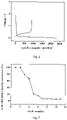
- Fig. 4 was the profile of the first charging and discharging of the coin cell which was based on the lithium-containing negative electrode material S-1 of example 1. As shown in the figure, the lithium-containing negative electrode material S-1 of example 1 had a reversible charging capacity of 3000 mAh/g and an ICE of 86.9%.
- Fig. 5 was the profile of the cycle stability of the coin cell which was based on the lithium-containing negative electrode material S-1 of example 1. As shown in the figure, the lithium-containing negative electrode material S-1 of example 1 had a charging capacity retention of about 92% after 20 charging and discharging cycles at a current rate of 0.2C.
- a coin cell was prepared and subjected to the tests for electrical properties as outlined in example 1 except that the lithium-containing negative electrode material S-1 was replaced with the negative electrode material D-1 obtained in comparative example 1.
- Fig. 6 was the profile of the first charging and discharging of the coin cel which was based on the negative electrode material D-1 of comparative example 1. As shown in the figure, the negative electrode material D-1 of comparative example 1 had a reversible charging capacity of 908 mAh/g and an ICE of 38.9%.
- Fig. 7 was the profile of the cycle stability of the coin cellwhich was based on the negative electrode material of comparative example 1. As shown in the figure, the negative electrode material of comparative example 1 had a charging capacity retention of 6% after 12 charging and discharging cycles at a current rate of 0.2C.
- Example 1 was repeated except that the obtained slurry after ultrasonically stirring was dried in air (at a temperature of 100 °C) for 12h. Obtained was the lithium-containing negative electrode material D-2.
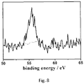
- Fig. 8 was the Li-Is XPS spectrum of the lithium-containing negative electrode material D-2. As shown in Fig. 8 , a signal peak appeared at the binding energy of 56.3 eV. It was attributable to the signal peak for the organic lithium salt (i.e. lithium polyacrylate). There was not the significant signal peak at the binding energy of 64.1 eV, which was corresponding to the complex of LiC 6 . It indicated that no intercalation of lithium ions in the porous carbon film occurred.
- the organic lithium salt i.e. lithium polyacrylate
- a coin cell was prepared and subjected to the tests for electrical properties as outlined in example 1 except that the lithium-containing negative electrode material S-1 was replaced with the material obtained in comparative example 2.
- the test results showed that, the material of comparative example 2 had a reversible charging capacity of 795 mAh/g and an ICE of 36.3%.
- the material had a charging capacity retention of about 30% after 20 charging and discharging cycles at a current rate of 0.2C.
- Example 1 was repeated except that lithium polyacrylate was replaced with lithium carbonate in the same amount. Obtained was the lithium-containing negative electrode material D-3.
- a coin cell was prepared and subjected to the tests for electrical properties as outlined in example 1 except that the lithium-containing negative electrode material S-1 was replaced with the material obtained in comparative example 3.
- the test results showed that, the material of comparative example 3 had a reversible charging capacity of 820 mAh/g and an ICE of 31%.
- the material had a charging capacity retention of about 10% after 10 charging and discharging cycles at a current rate of 0.2C.
- the lithium-containing negative electrode material S-2 had a TEM image, a full XPS spectrum and a Li-1s XPS spectrum that were similar to Fig. 1 to Fig. 3 respectively. It indicated that the obtained lithium-containing negative electrode material S-2 had a core-shell structure, wherein the outer surface of the core was coated with a porous carbon film, and lithium ions were intercalated in the porous carbon film.
- a coin cell was prepared and subjected to the tests for electrical properties as outlined in example 1 except that the lithium-containing negative electrode material S-1 was replaced with the material obtained in example 2.
- the test results showed that, the material of example 2 had a reversible charging capacity of 2812 mAh/g and an ICE of 87.6%.
- the material had a charging capacity retention of about 90% after 15 charging and discharging cycles at a current rate of 0.2C.
- the lithium-containing negative electrode material S-3 had a TEM image, a full XPS spectrum and a Li-1s XPS spectrum that were similar to Fig. 1 to Fig. 3 respectively. It indicated that the obtained lithium-containing negative electrode material S-3 had a core-shell structure, wherein the outer surface of the core was coated with a porous carbon film, and lithium ions were intercalated in the porous carbon film.
- a coin cell was prepared and subjected to the tests for electrical properties as outlined in example 1 except that the lithium-containing negative electrode material S-1 was replaced with the material obtained in example 3.
- the test results showed that, the material of example 3 had a reversible charging capacity of 2760 mAh/g and an ICE of 89.3%.
- the material had a charging capacity retention of about 85% after 15 charging and discharging cycles at a current rate of 0.2C.
- the lithium-containing negative electrode material S-4 had a TEM image, a full XPS spectrum and a Li-1s XPS spectrum that were similar to Fig. 1 to Fig. 3 respectively. It indicated that the obtained lithium-containing negative electrode material S-4 had a core-shell structure, wherein the outer surface of the core was coated with a porous carbon film, and lithium ions were intercalated in the porous carbon film.
- a coin cell was prepared and subjected to the tests for electrical properties as outlined in example 1 except that the lithium-containing negative electrode material S-1 was replaced with the material obtained in example 4.
- the test results showed that, the material of example 4 had a reversible charging capacity of 2720 mAh/g and an ICE of 87.9%.
- the material had a charging capacity retention of about 85% after 15 charging and discharging cycles at a current rate of 0.2C.
- the lithium-containing negative electrode material S-5 had a TEM image, a full XPS spectrum and a Li-1s XPS spectrum that were similar to Fig. 1 to Fig. 3 respectively. It indicated that the obtained lithium-containing negative electrode material S-5 had a core-shell structure, wherein the outer surface of the core was coated with a porous carbon film, and lithium ions were intercalated in the porous carbon film.
- a coin cell was prepared and subjected to the tests for electrical properties as outlined in example 1 except that the lithium-containing negative electrode material S-1 was replaced with the material obtained in example 5.
- the test results showed that, the material of example 5 had a reversible charging capacity of 2870 mAh/g and an ICE of 86.1%.
- the material had a charging capacity retention of about 91% after 18 charging and discharging cycles at a current rate of 0.2C.
- the lithium-containing negative electrode material S-6 had a TEM image, a full XPS spectrum and a Li-1s XPS spectrum that were similar to Fig. 1 to Fig. 3 respectively. It indicated that the obtained lithium-containing negative electrode material S-6 had a core-shell structure, wherein the outer surface of the core was coated with a porous carbon film and graphite, and lithium ions were intercalated in the porous carbon film.
- a coin cell was prepared and subjected to the tests for electrical properties as outlined in example 1 except that the lithium-containing negative electrode material S-1 was replaced with the material obtained in example 6.
- the test results showed that, the material of example 6 had a reversible charging capacity of 912 mAh/g and an ICE of 90.6%.
- the material had a charging capacity retention of about 96% after 100 charging and discharging cycles at a current rate of 0.2C.
- the lithium-containing negative electrode material S-7 had a TEM image, a full XPS spectrum and a Li-1s XPS spectrum that were similar to Fig. 1 to Fig. 3 respectively. It indicated that the obtained lithium-containing negative electrode material S-7 had a core-shell structure, wherein the outer surface of the core was coated with a porous carbon film and graphite, and lithium ions were intercalated in the porous carbon film.
- a coin cell was prepared and subjected to the tests for electrical properties as outlined in example 1 except that the lithium-containing negative electrode material S-1 was replaced with the material obtained in example 7.
- the test results showed that, the material of example 7 had a reversible charging capacity of 752 mAh/g and an ICE of 91.2%.
- the material had a charging capacity retention of about 96% after 150 charging and discharging cycles at a current rate of 0.2C.
- the lithium-containing negative electrode material S-8 had a TEM image, a full XPS spectrum and a Li-1s XPS spectrum that were similar to Fig. 1 to Fig. 3 respectively. It indicated that the obtained lithium-containing negative electrode material S-8 had a core-shell structure, wherein the outer surface of the core was coated with a porous carbon film and graphite, and lithium ions were intercalated in the porous carbon film.
- a coin cell was prepared and subjected to the tests for electrical properties as outlined in example 1 except that the lithium-containing negative electrode material S-1 was replaced with the material obtained in example 8.
- the test results showed that, the material of example 8 had a reversible charging capacity of 1512 mAh/g and an ICE of 88.9%.
- the material had a charging capacity retention of about 90% after 150 charging and discharging cycles at a current rate of 0.2C.
- the lithium-containing silicon monoxide-based negative electrode material of S-9 had a TEM image, a full XPS spectrum and a Li-Is XPS spectrum that were similar to Fig. 1 to Fig. 3 respectively. It indicated that the obtained lithium-containing silicon monoxide-based negative electrode material of S-9 had a core-shell structure, wherein the outer surface of the core was coated with a porous carbon film, and lithium ions were intercalated in the porous carbon film.
- a coin cell was prepared and subjected to the tests for electrical properties as outlined in example 1 except that the lithium-containing negative electrode material S-1 was replaced with the material obtained in example 9.
- the test results showed that, the material of example 9 had a reversible charging capacity of 1632 mAh/g and an ICE of 83.1%.
- the material had a charging capacity retention of about 90% after 200 charging and discharging cycles at a current rate of 0.2C.
- the lithium-containing silicon-aluminum-based negative electrode material S-10 had a TEM image, a full XPS spectrum and a Li-Is XPS spectrum that were similar to Fig. 1 to Fig. 3 respectively. It indicated that the obtained lithium-containing silicon-aluminum-based negative electrode material S-10 had a core-shell structure, wherein the outer surface of the core was coated with a porous carbon film, and lithium ions were intercalated in the porous carbon film.
- a coin cell was prepared and subjected to the tests for electrical properties as outlined in example 1 except that the lithium-containing negative electrode material S-1 was replaced with the material obtained in example 10.
- the test results showed that, the material of example 10 had a reversible charging capacity of 721 mAh/g and an ICE of 84.1%.
- the material had a charging capacity retention of about 90% after 200 charging and discharging cycles at a current rate of 0.2C.
- Example 1 was repeated except that petroleum pitch was replaced with coat tar pitch in the same amount. Obtained was the lithium-containing negative electrode material S-11.
- the median particle size and the content of each component of the lithium-containing negative electrode material S-11 were listed in Table 1.
- the lithium-containing negative electrode material S-11 had a TEM image, a full XPS spectrum and a Li-1s XPS spectrum that were similar to Fig. 1 to Fig. 3 respectively. It indicated that the obtained lithium-containing negative electrode material S-11 had a core-shell structure, wherein the outer surface of the core was coated with a porous carbon film, and lithium ions were intercalated in the porous carbon film.
- a coin cell was prepared and subjected to the tests for electrical properties as outlined in example 1 except that the lithium-containing negative electrode material S-1 was replaced with the material obtained in example 11.
- the test results showed that, the material of example 11 had a reversible charging capacity of 2932 mAh/g and an ICE of 88.7%.
- the material had a charging capacity retention of about 85% after 30 charging and discharging cycles at a current rate of 0.2C.
- Example 1 was repeated except that lithium polyacrylate was replaced with lithium polymethacrylate in the same amount. Obtained was the lithium-containing negative electrode material S-12.
- the median particle size and the content of each component of the lithium-containing negative electrode material S-12 were listed in Table 1.
- the lithium-containing negative electrode material S-12 had a TEM image, a full XPS spectrum and a Li-1s XPS spectrum that were similar to Fig. 1 to Fig. 3 respectively. It indicated that the obtained lithium-containing negative electrode material S-12 had a core-shell structure, wherein the outer surface of the core was coated with a porous carbon film, and lithium ions were intercalated in the porous carbon film.
- a coin cell was prepared and subjected to the tests for electrical properties as outlined in example 1 except that the lithium-containing negative electrode material S-1 was replaced with the material obtained in example 12.
- the test results showed that, the material of example 12 had a reversible charging capacity of 2895 mAh/g and an ICE of 87.1%.
- the material had a charging capacity retention of about 85% after 30 charging and discharging cycles at a current rate of 0.2C.
- Example 1 was repeated except that lithium polyacrylate was replaced with lithium polymaleate in the same amount. Obtained was the lithium-containing negative electrode material S-13.
- the median particle size and the content of each component of the lithium-containing negative electrode material S-13 were listed in Table 1.
- the lithium-containing negative electrode material S-13 had a TEM image, a full XPS spectrum and a Li-1s XPS spectrum that were similar to Fig. 1 to Fig. 3 respectively. It indicated that the obtained lithium-containing negative electrode material S-13 had a core-shell structure, wherein the outer surface of the core was coated with a porous carbon film, and lithium ions were intercalated in the porous carbon film.
- a coin cell was prepared and subjected to the tests for electrical properties as outlined in example 1 except that the lithium-containing negative electrode material S-1 was replaced with the material obtained in example 13.
- the test results showed that, the material of example 13 had a reversible charging capacity of 2925 mAh/g and an ICE of 86.8%.
- the material had a charging capacity retention of about 85% after 30 charging and discharging cycles at a current rate of 0.2C.
- Example 1 was repeated except that lithium polyacrylate was replaced with lithium polyfumarate in the same amount. Obtained was the lithium-containing negative electrode material S-14.
- the median particle size and the content of each component of the lithium-containing negative electrode material S-14 were listed in Table 1.
- the lithium-containing negative electrode material S-14 had a TEM image, a full XPS spectrum and a Li-1s XPS spectrum that were similar to Fig. 1 to Fig. 3 respectively. It indicated that the obtained lithium-containing negative electrode material S-14 had a core-shell structure, wherein the outer surface of the core was coated with a porous carbon film, and lithium ions were intercalated in the porous carbon film.
- a coin cell was prepared and subjected to the tests for electrical properties as outlined in example 1 except that the lithium-containing negative electrode material S-1 was replaced with the material obtained in example 14.
- the test results showed that, the material of example 14 had a reversible charging capacity of 2963 mAh/g and an ICE of 86.5%.
- the material had a charging capacity retention of about 85% after 30 charging and discharging cycles at a current rate of 0.2C.
- a coin cell was prepared and subjected to the tests for electrical properties as outlined in example 1 except that the lithium-containing negative electrode material S-1 was replaced with the material S-15 obtained in example 15.
- the test results showed that, the material of example 15 had a reversible charging capacity of 3480 mAh/g and an ICE of 91.2%.
- the material had a charging capacity retention of 94.8% after 30 charging and discharging cycles at a current rate of 0.2C.
- Example 1 84.39 10.55 5.06 0 0.32 Comparative example 1 94.34 0 5.66 0 0.28 Comparative example 2 84.39 10.59 5.02 0 0.32 Comparative example 3 84.39 10.65 4.96 0 0.46 Example 2 85.47 12.83 1.70 0 0.32 Example 3 74.61 22.44 2.95 0 0.75 Example 4 73.53 23.53 2.94 0 2.3 Example 5 68.50 28.77 2.73 0 5.7 Example 6 84.03 12.61 3.36 80 10.8 Example 7 84.02 12.69 3.29 83.3 13.5 Example 8 84.07 12.64 3.29 50 7.3 Example 9 84.04 12.60 3.27 0 0.42 Example 10 84.14 12.61 3.25 0 0.65 Example 11 84.49 10.6 4.91 0 0.48 Example 12 84.49 10.57 4.95
- the negative electrode materials according to the present disclosure had improved reversible charging capacity. When used in a lithium ion battery, it could improve the energy density of the lithium battery. More important, the negative electrode material of the present disclosure is simultaneously provided with improved initial coulombic efficiency and cycle charging capacity retention, especially cycle charging capacity retention in prolonged term.
Landscapes
- Chemical & Material Sciences (AREA)
- Chemical Kinetics & Catalysis (AREA)
- Electrochemistry (AREA)
- General Chemical & Material Sciences (AREA)
- Engineering & Computer Science (AREA)
- Composite Materials (AREA)
- Materials Engineering (AREA)
- Manufacturing & Machinery (AREA)
- Inorganic Chemistry (AREA)
- Battery Electrode And Active Subsutance (AREA)
- Secondary Cells (AREA)
Abstract
Description
- The present disclosure relates to the field of lithium ion batteries. More particular, the present disclosure relates to a negative electrode material in a core-shell structure, a preparation method therefor and an application thereof, and a lithium-ion battery.
- Silicon has a theoretical specific capacity of 4200 mAh/g, which is the battery negative electrode material with the highest capacity per gram at present. Once successfully applied, it can significantly improve the energy density of a lithium battery, making it possible to achieve a range of 1000 kilometers on one charge. However, silicon has charging/discharging mechanism which is different from graphite. Solid electrolyte interface (SEI) films may continuously form at the interface between Si and Li ions in electrolyte during charging and discharging. The formation of irreversible SEI may consume a lot of Li ions from electrolyte and positive electrode materials. Therefore, the initial cycle coulombic efficiency (also referred as the initial coulombic efficiency, ICE) of silicon-based negative electrode materials is usually only 65-85%, which results in a large capacity loss. In addition, silicon has conductivity and lithium ion diffusion rate that are both lower than those of graphite, which may limit the performance of silicon under high current and high power conditions.
- In order to solve the above problems, it has been proposed by scientific researchers to improve the comprehensive electrical performances of silicon-based negative electrode materials by doping, nanosizing and the like. The Chinese patent
CN101179126B discloses a doped silicon-based negative electrode material for lithium ion batteries. By doping at least one element of boron, aluminum, gallium, antimony and phosphorus, the initial coulombic efficiency of the material is improved.CN101179126B needs high vacuum argon arc fusion welding in the preparation process, which requires high reaction temperature (> 1000 °C), complex reactions (involving fusion welding, low-temperature blowing, rapid cooling, planetary ball milling and other operations), and thereby high cost.CN108172775A discloses a phosphorus doped silicon-based negative electrode material. Its examples show that the phosphorus doped silicon-based negative electrode has an initial coulombic efficiency of 91.7% with a specific capacity of 610.1mAh/g. The preparation process ofCN108172775A requires spray drying and results in low yield but high cost.CN103400971A discloses lithium silicate doped negative electrode materials. When silicon is added in an amount of 50% and Li2SiO3 in an amount of 35%, the resulting material has a specific capacity of 1156.2 mAh/g and an initial coulombic efficiency of 88.2%. There is a margin to further improve the cycle stability and initial coulombic efficiency of the material.CN111653738A discloses a negative electrode material of amorphous carbon coated silicon-carbon in core-shell structure. The material has a reversible charging capacity of 1765.54 mAh/g, an ICE of 84.38%, and a charging capacity retention of 82.24% after 50 cycles, for which there is margin for further improvement. - As mentioned above, although some progress has been made in the modification of silicon-based negative electrode materials, it can usually only improve one performance of silicon-based negative electrode materials, rather than improve their comprehensive electrical properties. However, when used in high energy density lithium ion batteries, it is desired that the negative electrode material simultaneously has excellent reversible charging capacity, initial coulombic efficiency and cycle charging capacity retention, especially excellent initial coulombic efficiency and cycle charging capacity retention at the same time. Therefore, there is still demand for developing silicon-based negative electrode materials with simultaneously improved initial coulombic efficiency, reversible charging capacity, cycle charging capacity retention and conductivity. A simple method for preparing such silicon-based negative electrode materials is also needed.
- The disclosure is to solve the problems of low reversible charging capacity and low initial coulombic efficiency of silicon-based negative electrode materials in the prior art. Provided is a negative electrode material in a core-shell structure, a preparation method for the negative electrode material and the negative electrode material obtained by the preparation method, as well as a lithium ion battery. The negative electrode material of the present disclosure has improved reversible charging capacity (also referred as reversible charging specific capacity) and initial coulombic efficiency, and is particularly suitable for lithium ion batteries.
- In order to achieve the above purpose, provided in the first aspect of the present disclosure is a negative electrode material which has a core-shell structure, wherein the core comprises a silicon-containing material, the shell comprises an organic lithium salt and a porous carbon film, and wherein at least a part of lithium ion is intercalated in the porous carbon film.
- Preferably, the organic lithium salt is at least one selected from the group consisting of lithium polyacrylate, lithium polymethacrylate, lithium polymaleate, lithium polyfumarate, lithium carboxymethylcellulose and lithium alginate.
- Provided in the second aspect of the present disclosure is a method for preparing a negative electrode material, comprising:
- (1) mixing a silicon source and a carbon source, and then calcining the mixture;
- (2) mixing the calcined product obtained in the step (1) with an organic lithium salt; and
- (3) subjecting the materials obtained in the step (2) of mixing to vacuum freeze-drying.
- Preferably, the carbon source is pitch, preferably at least one selected from the group consisting of petroleum pitch, coal tar pitch, natural pitch and modified pitch.
- Provided in the third aspect of the present disclosure is the negative electrode material prepared by the above method.
- Provided in the fourth aspect of the present disclosure is the use of the above negative electrode material in a lithium ion battery.
- Provided in the fifth aspect of the present disclosure is a lithium ion battery comprising the above negative electrode material, a lithium-containing positive electrode material, a separator and an electrolyte.
- Specifically, the present disclosure may be embodied in the following items:
- 1. A negative electrode material of silicon-carbon, characterized in that the negative electrode material of silicon-carbon has a core-shell structure, wherein the core comprises a silicon-containing material, the shell comprises an organic lithium salt and a porous carbon film.
- 2. The negative electrode material of silicon-carbon of
item 1, wherein the porous carbon film coats the outer surface of the core, and the organic lithium salt is present in the porous carbon film. - 3. The negative electrode material of silicon-carbon of
item 1, wherein, based on the total amount of the negative electrode material of silicon-carbon, the organic lithium salt is present in an amount of 5-34 wt%, the silicon-containing material is present in an amount of 65-90 wt%, and the porous carbon film is present in an amount of 1-10 wt%;- preferably, based on the total amount of the negative electrode material of silicon-carbon, the organic lithium salt is present in an amount of 10-30 wt%, the silicon-containing material is present in an amount of 68-86 wt%, and the porous carbon film is present in an amount of 1-6 wt%;
- preferably, the negative electrode material of silicon-carbon further comprises graphite; further preferably, the graphite is present in the core and/or the shell;
- preferably, the mass ratio of the total amount of the silicon-containing material, the organic lithium salt and the porous carbon film to the amount of graphite is 1:1-10, further preferably 1:1-5.
- 4. The negative electrode material of silicon-carbon of
item 1, wherein the negative electrode material of silicon-carbon has a median particle size of 0.1-20 µm. - 5. The negative electrode material of silicon-carbon of any one of items 1-4, wherein the organic lithium salt is at least one selected from the group consisting of lithium polyacrylate, lithium polymethacrylate, lithium polymaleate, lithium polyfumarate, lithium carboxymethylcellulose and lithium alginate;
preferably, the silicon-containing material is at least one selected from the group consisting of elemental silicon, SiOx wherein 0.6 < x < 1.5, and silicon-containing alloy; preferably, the silicon-containing alloy is at least one selected from the group consisting of silicon-aluminum alloy, silicon-magnesium alloy, silicon-zirconium alloy and silicon-boron alloy. - 6. A method for preparing a negative electrode material of silicon-carbon, comprising the steps of:
- (1) mixing a silicon source and a carbon source, and then calcining the mixture;
- (2) mixing the calcined product obtained in the step (1) with an organic lithium salt; and
- (3) subjecting the materials obtained in the step (2) of mixing to vacuum freeze-drying.
- 7. The method of
item 6, wherein the silicon source is at least one selected from the group consisting of elemental silicon, SiOx wherein 0.6 < x < 1.5, and silicon-containing alloy; preferably, the silicon-containing alloy is at least one selected from the group consisting of silicon-aluminum alloy, silicon-magnesium alloy, silicon-zirconium alloy and silicon-boron alloy;- preferably, the carbon source is at least one selected from the group consisting of petroleum pitch, coal tar pitch, natural pitch and modified pitch;
- preferably, the mass ratio of the silicon source to the carbon source is 1: (0.04-0.12).
- 8. The method of
item 6, wherein the step (1) of mixing comprises:- adding the silicon source and the carbon source into an organic solvent, and then stirring ultrasonically, preferably for 10-100min;
- preferably, the organic solvent is at least one selected from the group consisting of N,N-dimethylformamide, N,N-dimethylacetamide and N-methylpyrrolidone;
- preferably, the calcining is operated under an inert atmosphere at a temperature of 600-1000 °C, preferably 700-900 °C, for 10-240 min, preferably 20-60 min.
- 9. The method of any one of items 6-8, wherein the organic lithium salt is at least one selected from the group consisting of lithium polyacrylate, lithium polymethacrylate, lithium polymaleate, lithium polyfumarate, lithium carboxymethylcellulose and lithium alginate;
- preferably, the organic lithium salt is used in an amount of 0.05-0.5 parts by weight, preferably 0.1-0.4 parts by weight in relative to 1 part by weight of the silicon source;
- preferably, the step (2) of mixing includes: adding the calcined product obtained in the step (1) and the organic lithium salt into the solvent and stirring for 4-48 h.
- 10. The method of any one of items 6-9, wherein the vacuum freeze-drying of the step (3) is operated at a temperature of not higher than -65 °C and a vacuum degree of not higher than 120 Pa for a time of 4-48 h.
- 11. The method of any one of items 6-10, further comprises adding graphite in the step (1) and/or the step (2).
- 12. The method of any one of items 6-10, further comprises the step (4) of: mixing the product obtained in the vacuum freeze-drying in the step (3) with graphite;
preferably, graphite is used in an amount of 1-15 parts by weight, preferably 1-5 parts by weight in relative to 1 part by weight of the product obtained in the vacuum freeze-drying in the step (3). - 13. The negative electrode material of silicon-carbon prepared by the method of any one of items 6-12.
- 14. Use of the negative electrode material of silicon-carbon of any one of items 1-5 and 13 in a lithium ion battery.
- 15. A lithium ion battery comprising the negative electrode material of silicon-carbon of any one of items 1-5 and 13, a lithium-containing positive electrode material, a separator and an electrolyte;
preferably, the lithium ion battery is a liquid lithium ion battery, a semi-solid lithium ion battery or a solid lithium ion battery. - The negative electrode material in core-shell structure in accordance with the present disclosure comprises lithium element, and at least a part of the lithium element is intercalated in the porous carbon film in the form of ions. It can not only solve the problems of low reversible charging capacity and low initial coulombic efficiency of the traditional silicon-based negative electrode, but also inhibit the pulverization of the electrode material caused by the "volume effect" during the charging and discharging of the traditional silicon-based negative electrode and the uncontrollable growth of SEI films, and the like. The negative electrode material in accordance with the present disclosure does not need pre-lithiating when used, greatly improves the reversible charging capacity of the negative electrode material, and can significantly improve the energy density of the lithium battery.
-
-
Fig. 1 shows a TEM image of the negative electrode material S-1 prepared in example 1, wherein A is a core of nano silicon and B is a shell; -
Fig. 2 shows a full X-ray photoelectron spectroscopy (XPS) spectrum of the negative electrode material S-1 prepared in example 1; -
Fig. 3 shows a Li-Is XPS spectrum of the negative electrode material S-1 prepared in example 1; -
Fig. 4 shows the profile of the first charging and discharging of the negative electrode material S-1 prepared in example 1; -
Fig. 5 shows the profile of the cycle stability of the negative electrode material S-1 prepared in example 1; -
Fig. 6 shows the profile of the first charging and discharging of the negative electrode material D-1 prepared in comparative example 1; -
Fig. 7 shows the profile of the cycle stability of the negative electrode material D-1 prepared in comparative example 1; and -
Fig. 8 shows a Li-Is XPS spectrum of the negative electrode material D-2 prepared in comparative example 2. - It should be understood that the endpoints and any values in the ranges disclosed herein are not limited to the precise range or value, but to encompass values close to those ranges or values. For ranges of values, it is possible to combine between the endpoints of each of the ranges, between the endpoints of each of the ranges and the individual points, and between the individual points to give one or more new ranges of values as if these ranges of values are specifically disclosed herein. Other than in the examples, all numerical values of parameters in this specification are to be understood as being modified in all instances by the term "about" whether or not "about" actually appears before the numerical value.
- In this specification, the core-shell structure refers to an assembly structure formed by using one material (such as the carbon source and organic lithium salt in the present disclosure) to uniformly coat another material (such as the silicon source in the present disclosure) through chemical bond or other force. Preferably, the negative electrode material in core-shell structure of the present disclosure is in nano size.
- In this specification, the median particle size (or D50) refers to the particle size when the cumulative particle size distribution percentage reaches 50%. The median particle size is often used to represent the average particle size of powders. In the present disclosure, unless otherwise indicated, the median particle size of the negative electrode material may be characterized by dynamic light scattering.
- In the first aspect of the present disclosure, provided is a negative electrode material which has a core-shell structure, wherein the core comprises a silicon-containing material, the shell comprises an organic lithium salt and a porous carbon film, and wherein at least part of lithium ion is intercalated in the porous carbon film.
- Such arrangements can not only improve the transmission rate of lithium ion, but also significantly improve the initial coulombic efficiency of the material. Preferably, the negative electrode material in accordance with the present disclosure may further comprise a phosphorus-containing coating layer. The phosphorus-containing coating layer may be between the core and the shell. The phosphorus-containing coating layer may comprise a polymer having polycyclic aromatic hydrocarbon structural segments. In one variant, the 13C-NMR spectrum of the polymer having polycyclic aromatic hydrocarbon structural segments involves signal peaks at 110 ppm-140 ppm, indicating the presence of the polycyclic aromatic hydrocarbon structural segments. Message relating to the chemical shifts of polycyclic aromatic hydrocarbons in 13C-NMR spectrum is disclosed in: Harris, K. J., Reeve Z. E. M., et al. Electrochemical Changes in Lithium-Battery Electrodes Studied Using 7Li NMR and Enhanced 13C NMR of Graphene and Graphitic Carbons [J]. Chem. Mater. 2015, 27, 9, pp 3299-3305, which is fully incorporated herein by reference. Phosphorus in the phosphorus-containing coating layer and silicon in the silicon-containing material are connected via a chemical bond, preferably P(O)-O-Si. The connecting of phosphorus and silicon via P(O)-O-Si may be characterized by X-ray photoelectron spectroscopy or 29Si-NMR spectrum.
- Preferably, the negative electrode material in accordance with the present disclosure may further comprise graphite. Although the theoretical capacity of carbon is much lower than that of silicon, the introduction of graphite into the negative electrode material can compensate the low conductivity of silicon and simultaneously greatly improve the cycle charging capacity retention. In addition, the use of graphite does not suffer from the problem of volume expansion experienced by silicon negative electrode materials during charging and discharging. There is not any special limitation on the position of graphite in the invention. Due to the difference in the processing conditions in the preparations, graphite may be present in the core, in the shell, or both.
- According to a preferred embodiment of the present disclosure, graphite is present in the core and/or shell.
- Preferably, the silicon-containing material is at least one selected from the group consisting of elemental silicon, SiOx wherein 0.6 < x < 1.5, and silicon-containing alloys. The silicon-containing materials may be commercially available or prepared by known methods.
- Preferably, the silicon-containing alloy is at least one selected from the group consisting of silicon-aluminum alloy, silicon-magnesium alloy, silicon-zirconium alloy and silicon-boron alloy. The content of silicon in the silicon-containing alloys may be selected within a wide range. For example, based on the total amount of the silicon-containing alloy, silicon may be present in an amount of 10-50 wt%. There is not any special limitation on the method for preparing the silicon-containing alloy. Provided herein is a specific method for preparing a silicon-containing alloy. However, the present disclosure is not limited thereto. For example, a method for preparing a silicon-aluminum alloy may comprise the steps of: 1) ball milling aluminum powder and silicon powder for 30 min under an inert protection atmosphere; and 2) treating the mixture obtained in the above step at 900 °C for 10 hours.
- Preferably, the organic lithium salt may be those salts formed from a compound containing an organic acid functional group (preferably carboxyl group) and an alkaline compound containing lithium. Preferably, the organic lithium salt may be at least one selected from the group consisting of lithium polyacrylate, lithium polymethacrylate, lithium polymaleate, lithium polyfumarate, lithium carboxymethylcellulose and lithium alginate. The molecular weight of the organic lithium salt may be selected within a wide range. Preferably, the organic lithium salt may have a weight average molecular weight of 2000-5000000, more preferably 80000-300000.
- The contents of components in the negative electrode material in accordance with the present disclosure may be selected within a wide range. Preferably, based on the total amount of the negative electrode material, the organic lithium salt may be present in an amount of 5-34 wt%, the silicon-containing material may be present in an amount of 65-90 wt%, and the porous carbon film may be present in an amount of 1-10 wt%. More preferably, based on the total amount of the negative electrode material, the organic lithium salt may be present in an amount of 10-30 wt%, the silicon-containing material may be present in an amount of 68-86 wt%, and the porous carbon film may be present in an amount of 1-6 wt%.
- According to a preferred embodiment of the present disclosure, the negative electrode material may further comprise graphite. Further preferably, graphite may be present in the core and/or the shell, more preferably in the shell.
- The content of graphite may be selected within a wide range. Preferably, the mass ratio of the total amount of the silicon-containing material, the organic lithium salt and the porous carbon film to the amount of graphite is 1:1-10, further preferably 1:1-5.
- Preferably, the negative electrode material has a median particle size of 0.1-20 µm, such as 0.1 µm, 0.5 µm, 1 µm, 10 µm, 15 µm, 20 µm, and any value in the range formed by any two of those values.
- In the second aspect of the present disclosure, provided is a method for preparing a negative electrode material, comprising the steps of:
- (1) mixing a silicon source and a carbon source, and then calcining the mixture;
- (2) mixing the calcined product obtained in the step (1) with an organic lithium salt; and
- (3) subjecting the materials obtained in the step (2) of mixing to vacuum freeze-drying.
- Preferably, the silicon source may be the silicon-containing material mentioned above, or a silicon-containing precursor that can be converted into the silicon-containing material by the calcining. Further preferably, the silicon source may be the silicon-containing material mentioned above. The suitable materials may be selected as described above, which is not repeated here.
- Preferably, the carbon source is pitch, preferably at least one selected from the group consisting of petroleum pitch, coal tar pitch, natural pitch and modified pitch. Such preferred arrangements are advantageous to the formation of the porous carbon and thereby can improve the electrochemical performances of the prepared negative electrode material.
- The petroleum pitch, coal tar pitch, natural pitch and modified pitch have the meanings commonly understood by those skilled persons in the art and may be commercially available.
- The amount of the carbon source depends on the amount of the silicon source. Preferably, the mass ratio of the silicon source to the carbon source is 1: (0.04-0.12), such as 1:0.04, 1:0.05, 1:0.06, 1:0.07, 1:0.08, 1:0.09, 1:0.10, 1:0.11, 1:0.12, and any value in the range formed by any two of those values.
- Preferably, the step (1) of mixing includes: adding the silicon source and the carbon source to an organic solvent, and then stirring ultrasonically. Such preferred arrangements are advantageous to the uniform coating of the carbon source on the surface of silicon.
- The time of the ultrasonically stirring may be selected within a wide range. It is judged by whether the silicon source and carbon source can be dispersed in the organic solvent. Preferably, the time of the ultrasonically stirring is 10-100min, further preferably 20-60min.
- The organic solvent may be an organic solvent commonly used in the art, preferably at least one selected from the group consisting of N,N-dimethylformamide, N,N-dimethylacetamide and N-methylpyrrolidone.
- The amount of the organic solvent may be selected within a wide range. For example, the slurry obtained by the mixing may have a solid content of 10-35 wt%.
- According to an embodiment of the present disclosure, the method may further comprise: separating the mixed material after the step (1) of mixing, and calcining the solid obtained by the separating. The separating may be operated by any conventional separation method in the art, such as centrifugal separation. Preferably, the method may further comprise: drying the solid obtained by the separating and then calcining. The conditions for the drying may be selected within a wide range. Preferably, it is operated at temperature of 80-150 °C for a time of 1-10 h.
- Preferably, the calcining may be operated under an inert atmosphere at a temperature of 600-1000 °C, preferably 700-900 °C, for a time of 10-240 min, preferably 20-60 min. The inert atmosphere may be provided by at least one selected from the group consisting of nitrogen, helium, argon and krypton. The examples of the present disclosure use nitrogen for illustrating. However, the present disclosure is not limited thereto.
- There is not any specific limitation on the heating rate during the calcining. For example, it may be 1-10°C/min. The examples of the present disclosure adopt 5°C/min for illustrating. However, the present disclosure is not limited thereto.
- According to an embodiment of the present disclosure, the method may comprise: operating the step (2) after the calcined product obtained in the step (1) is cooled (preferably to 50 °C or below, such as a room temperature of 25 °C). The cooling may be natural cooling.
- The suitable materials for the organic lithium salt may be selected as described above, which is not repeated here.
- Preferably, in relative to 1 part by weight of the silicon source, the organic lithium salt is used in an amount of 0.05-0.5 parts by weight, preferably 0.1-0.4 parts by weight.
- There is not any specific limitation on the operation for the step (2) of mixing the calcined product obtained in the step (1) with the organic lithium salt. Preferably, the step (2) of mixing may include: adding the calcined product obtained in the step (1) and the organic lithium salt into the solvent and stirring for 4-48 hours. The amount of solvent may be selected within a wide range. For example, the slurry obtained by mixing may have a solid content of 10-35 wt%. Preferably, the solvent is water.
- The vacuum freeze-drying in the step (3) can hold the structure of the porous carbon obtained in the calcining in the step (1), and make at least part of lithium ion intercalated in the porous carbon film.
- Theoretically, the lower the temperature and vacuum degree of vacuum freeze-drying, the better. However, as the temperature and vacuum degree decrease, the energy consumption increases. In fact, there is operation limitation for a vacuum freeze-drying equipment. Considering the energy consumption and effect, it is preferable that the vacuum freeze-drying of the step (3) is operated at a temperature of not higher than -65 °C, preferably -80°C to -65°C and a vacuum degree of not higher than 120 Pa, preferably 90-120 Pa.
- The time of the vacuum freeze-drying may be selected within a wide range. Preferably, the vacuum freeze-drying may be operated for 4-48 h, preferably 8-32 h.
- Preferably, the method may further comprise: forming a phosphorus-containing coating layer before the step (1). For example, the forming may be completed by a method comprising the steps of:
- (a) contacting the silicon-containing material, a phosphorus source and a solvent at 30-80 °C to graft the phosphorus source to the surface of the silicon-containing material; and
- (b) subjecting to a temperature programmed calcining to convert the phosphorus source around the silicon-containing material into the phosphorus-containing coating layer comprising the polymer having polycyclic aromatic hydrocarbon structural segments, wherein the temperature programmed calcining comprises:
- heating to a first temperature of 400-500 °C at a first heating rate,
- heating to a second temperature of 600-800 °C at a second heating rate, wherein the second heating rate is lower than the first heating rate, and
- keeping at the second temperature.
- The phosphorus source may be any phosphorus-containing precursor that can be converted into the polymer having polycyclic aromatic hydrocarbon structural segments, for example by polycondensation. The preferred phosphorus source is selected from the group consisting of organic polybasic phosphoric acid and its esters or salts. Preferably, the organic polybasic phosphoric acid is phytic acid. The preferable solvent for the step (a) may be at least one selected from the group consisting of toluene, N,N-dimethylformamide, N,N-dimethylacetamide and N-methylpyrrolidone. Preferably, the solvent may be present in such an amount that the material obtained in the step (a) has a solid content of 5-40 wt%. Preferably, the temperature programmed calcining may include: heating to a first temperature of 450-500 °C, such as 480 °C, at a first heating rate of 1-10 °C/min, preferably 5-10 °C/min; then heating to a second temperature of 600-650 °C, such as 620 °C, at a second heating rate of 1-5 °C/min, preferably 1-3 °C/min; and keeping at the second temperature for 1-8h, preferably 2-4h.
- Preferably, the method may further comprise the step of adding graphite. The graphite may be added in the step (1) and/or the step (2), or be added after the step (3).
- According to a preferred embodiment of the present disclosure, the method may further comprise the step of adding graphite in the step (1) and/or the step (2). In particular, the adding graphite in the step (1) may include, but not limited to: mixing the silicon source, the carbon source and graphite, and then calcining the mixture. In particular, the adding graphite in the step (2) may include, but not limited to: mixing the calcined product obtained in the step (1), the organic lithium salt and graphite.
- According to another preferred embodiment of the present disclosure, the method may further comprise the step (4) of: mixing the product obtained in the vacuum freeze-drying in the step (3) with graphite.
- It is preferable to add graphite in the step (4). Such preferred arrangements are advantageous to easily adjusting the reversible charging capacity of the prepared negative electrode material.
- According to a preferred embodiment of the present disclosure, in relative to 1 part by weight of the product obtained in the vacuum freeze-drying in the step (3), graphite is used in an amount of 1-15 parts by weight, preferably 1-5 parts by weight.
- In the third aspect of the present disclosure, provided is the negative electrode material prepared by the above method. The negative electrode material may have structure and chemical composition as described above, which is not repeated here.
- In the fourth aspect of the present disclosure, provided is use of the above negative electrode material in a lithium ion battery. Compared with the traditional pure graphite negative electrode material, the above negative electrode material contains silicon having higher theoretical capacity, which significantly improves the reversible charging capacity. Therefore, when the above negative electrode material is used in a lithium ion battery, the energy density of the lithium ion battery can be improved.
- In the fifth aspect of the present disclosure, provided is a lithium ion battery, comprising: the negative electrode material in accordance with the present disclosure, a lithium-containing positive electrode material, a separator and an electrolyte.
- The lithium ion battery in accordance with the present disclosure has a structure well known to those skilled persons in the art. In general, the separator is disposed between the positive electrode and the negative electrode. The positive electrode contains a positive electrode material and the negative electrode contains a negative electrode material. There is not any special limitation on the chemical composition of the positive electrode material. It may be a lithium-based positive electrode material commonly used in the art.
- In the lithium ion battery in accordance with the present disclosure, the separator may be selected from various separators commonly used in lithium-ion batteries, such as polypropylene microporous films, polyethylene mat, glass fiber mat or ultra-fine glass fiber paper.
- In the lithium ion battery in accordance with the present disclosure, the electrolyte may be various conventional electrolytes, such as non-aqueous electrolyte. The non-aqueous electrolyte is a solution formed by an electrolyte lithium salt in a non-aqueous solvent. Any traditional non-aqueous electrolyte known to those skilled persons in the art may be used. For example, the electrolyte may be at least one selected from the group consisting of lithium hexafluorophosphate (LiPF6), lithium perchlorate (LiClO4), lithium tetrafluoroborate (LiBF4), lithium hexafluoroarsenate (LiAsF6) and lithium hexafluorosilicate (LiSiF6). The non-aqueous solvents may be selected from the group consisting of linear esters and cyclic esters and mixtures thereof. The linear esters may be at least one selected from the group consisting of dimethyl carbonate (DMC), diethyl carbonate (DEC), methyl ethyl carbonate (EMC), methyl propyl carbonate (MPC) and dipropyl carbonate (DPC). The cyclic esters may be at least one selected from the group consisting of ethylene carbonate (EC), propylene carbonate (PC) and vinylene carbonate (VC).
- The invention will be described in detail below through the following examples. The examples are intended to illustrate and not to limit the invention in any way.
- The morphology of a sample of a negative electrode material was characterized with transmission electron microscope. Specifically, the transmission electron microscope used was JEM-2100 transmission electron microscope from Japan Electronics Co., Ltd., and the test conditions included acceleration voltage of 160KV. The sample was placed on the copper support net and then inserted into the electron microscope for observation. A magnification of 800000 was used for observation.
- The sample of a negative electrode material was characterized with ESCALAB 250Xi X-ray photoelectron spectroscopy tester from ThermoFisher Scientific Company of the United States. The test conditions included: room temperature of 25 °C, vacuum degree of less than 5 × 10⁻¹⁰ mba, working voltage of 15kV, Al Kα as the ray source, a full spectrum passing energy of 100eV and a step length of 1.0ev.
- The sample of a negative electrode material was characterized with ESCALAB 250Xi X-ray photoelectron spectroscopy tester from ThermoFisher Scientific Company of the United States. The test conditions included: room temperature of 25 °C, vacuum degree of less than 5 × 10⁻¹⁰ mba, working voltage of 15kV, Al Kα as the ray source, a narrow spectrum passing energy of 30eV, a step length of 0.05ev and a beam spot of 500 µm.
- The median particle size is characterized by dynamic light scattering according to GB/T 19077-2016.
- The negative electrode materials prepared in the following examples and comparative examples were assembled into lithium ion battery samples. The electrochemical properties of the obtained lithium ion battery samples were tested with Wuhan blue battery test system (CT2001B). The test conditions included voltage range of 0.005V-3V. Each negative electrode material was assembled into 10 samples in a form of coin cell. The battery performances of the samples were tested under the same voltage and current. The average value thereof was used as the measured value.
- At a voltage range of 0.05V-3V and a current rate of 0.1C, the assembled lithium ion battery samples were subjected to the first charging and discharging, and the profile of the first charging and discharging was obtained. The battery test system (CT2001B) gave the first discharge capacity and the first charge capacity of the tested battery sample. The first discharge capacity was the specific capacity of the negative electrode material, and the first charge capacity was the reversible charging capacity of the negative electrode material. The initial coulombic efficiency (also referred to as "ICE") could be calculated from them:
ICE = the reversible charging capacity of the negative electrode material / the specific capacity of the negative electrode material. - At a current rate of 0.2C, the assembled lithium ion battery sample was subjected to charging and discharging for selected cycles, such as 20, 50 or 100 cycles. The reversible charging capacity of the sample at each cycle was measured. The cycle charging capacity retention of each cycle was calculated according to the following:

- The profile of the cycle stability was plotted by taking the cycle numbers as the X-axis and the cycle charging capacity retention as the Y-axis.
- In the following examples and comparative examples, the petroleum pitch used was purchased from TIPCO Company with the brand of PMA. The coal tar pitch was purchased from Longxin material Trade Co., Ltd. with the brand of low-temperature pitch (100-115).
- Lithium polyacrylate was prepared. In particular, 10g of polyacrylic acid with a weight average molecular weight of 240000 was added to 40g deionized water to prepare a polyacrylic acid solution with a concentration of 20 mass %. To the polyacrylic acid solution, 3.4g lithium hydroxide was added. The mixture was heated at 40 °C under stirring until all solids were dissolved, and then dried at 100 °C for 4h to obtain lithium polyacrylate.
- Lithium polymethacrylate was prepared. In particular, 10g of polymethacrylic acid with a weight average molecular weight of 240000 was added to 40g deionized water to prepare a polymethacrylic acid solution with a concentration of 20 mass %. To the polymethacrylic acid solution, 3.4g lithium hydroxide was added. The mixture was heated at 40 °C under stirring until all solids were dissolved, and then dried at 100 °C for 4h to obtain lithium polymethacrylate.
- Lithium polymaleate was prepared. In particular, 10g of polymaleic acid with a weight average molecular weight of 240000 was added to 40g deionized water to prepare a polymaleic acid solution with a concentration of 20 mass %. To the polymaleic acid solution, 3.4g lithium hydroxide was added. The mixture was heated at 40 °C under stirring until all solids were dissolved, and then dried at 100 °C for 4h to obtain lithium polymaleate.
- Lithium polyfumarate was prepared. In particular, 10g of polyfumaric acid with a weight average molecular weight of 240000 was added to 40g deionized water to prepare a polyfumaric acid solution with a concentration of 20 mass %. To the polyfumaric acid solution, 3.4g lithium hydroxide was added. The mixture was heated at 40 °C under stirring until all solids were dissolved, and then dried at 100 °C for 4h to obtain lithium polyfumarate.
- Lithium carboxymethyl cellulose was prepared. In particular, 10g of sodium carboxymethyl cellulose with a weight average molecular weight of 120000 was added to 40g deionized water to prepare a sodium carboxymethyl cellulose solution with a concentration of 20 mass %. To the sodium carboxymethyl cellulose solution, 3.1g lithium hydroxide was added. The mixture was heated at 40 °C under stirring until all solids were dissolved, and then dried at 100 °C for 4h to obtain lithium carboxymethyl cellulose.
- Lithium alginate was prepared. In particular, 10g of sodium alginate with a weight average molecular weight of 80000 was added to 40g deionized water to prepare a sodium alginate solution with a concentration of 20 mass %. To the sodium alginate solution, 1.2g lithium hydroxide was added. The mixture was heated at 40 °C under stirring until all solids were dissolved, and then dried at 100 °C for 4h to obtain lithium alginate.
- Polyacrylic acid, polymethacrylic acid, polymaleic acid, polyfumaric acid, sodium carboxymethylcellulose and sodium alginate used were purchased from Aladdin reagent company.
- In the following examples and comparative examples, the room temperature was referred to 25 °C.
-
- (1) 1g of silicon powder with D50 of 120nm and 0.12g of petroleum pitch were added to 10g of N,N-dimethylformamide, and ultrasonically stirred for 40 minutes.
- (2) The slurry obtained after ultrasonically stirring was transferred to a 50 mL centrifuge tube and centrifuged at 5000 rpm for 5 minutes. The lower solids were collected and dried (at 100 °C for 4h).
- (3) The pitch coated silicon material obtained in the step (2) was treated in a tubular furnace by heating to 800 °C at a rate of 5 °C/min and keeping under nitrogen atmosphere for 30 minutes. After cooling naturally to the room temperature, obtained was a carbon coated silicon material.
- (4) 0.125g of lithium polyacrylate and the carbon coated silicon material obtained in the step (3) were added into 3 mL deionized water and stirred at the room temperature for 12h. Then, the obtained slurry after stirring was placed in a freeze vacuum drying oven with a cold trap temperature of - 80 °C and a cavity vacuum of 100 Pa to be dried for 12 hours. Obtained was the lithium-containing negative electrode material S-1. The median particle size and the content of each component of the lithium-containing negative electrode material S-1 were listed in Table 1.
- The lithium-containing negative electrode material S-1 was sampled and subjected to the test for identifying material as described above.
Fig. 1 was a TEM image of the lithium-containing negative electrode material S-1. As could be seen from the figure, silicon nanoparticles were uniformly coated to form a core-shell structure, wherein the outer surface of the core was covered with a porous carbon film.Fig. 2 was a full XPS spectrum of the lithium-containing negative electrode material S-1. As could be seen from the spectrum, the negative electrode material contained elements of lithium, carbon and silicon.Fig. 3 was the Li-Is XPS spectrum of the lithium-containing negative electrode material S-1. As shown inFig. 3 , a significant signal peak appeared at the binding energy of 64.1 eV. This signal peak corresponded to a complex of LiC6. The formation of the complex LiC6 indicated that Li ions migrated into the porous carbon film and were between layers of carbon atoms. That is, lithium ions were intercalated in the porous carbon film. - A CR2016 coin cell was assembled by using the lithium-containing negative electrode material S-1 obtained in example 1 and a metal lithium sheet as positive electrode and negative electrode respectively, 1 mol/L LiPF6 solution as electrolyte (wherein a mixture of vinyl carbonate and diethyl carbonate in a ratio of 3:7 by volume was used as solvents) and a polypropylene microporous film as separator. The battery was subjected to the tests for detecting electrical properties as described above, to characterize the electrical properties of the lithium-containing negative electrode material S-1 of example 1.
-
Fig. 4 was the profile of the first charging and discharging of the coin cell which was based on the lithium-containing negative electrode material S-1 of example 1. As shown in the figure, the lithium-containing negative electrode material S-1 of example 1 had a reversible charging capacity of 3000 mAh/g and an ICE of 86.9%. -
Fig. 5 was the profile of the cycle stability of the coin cell which was based on the lithium-containing negative electrode material S-1 of example 1. As shown in the figure, the lithium-containing negative electrode material S-1 of example 1 had a charging capacity retention of about 92% after 20 charging and discharging cycles at a current rate of 0.2C. -
- (1) 1g of silicon powder with D50 of 120nm and 0.12g of petroleum pitch were added to 10g of N,N-dimethylformamide, and ultrasonically stirred for 40 minutes.
- (2) The slurry obtained after ultrasonically stirring was transferred to a 50 mL centrifuge tube and centrifuged at 5000 rpm for 5 minutes. The lower solids were collected and dried (at 100 °C for 4h).
- (3) The pitch coated silicon material obtained in the step (2) was treated in a tubular furnace by heating to 800 °C at a rate of 5 °C/min and keeping under nitrogen atmosphere for 30 minutes. After cooling naturally to room temperature, obtained was a carbon coated silicon material, which was regarded as the negative electrode material D-1.
- A coin cell was prepared and subjected to the tests for electrical properties as outlined in example 1 except that the lithium-containing negative electrode material S-1 was replaced with the negative electrode material D-1 obtained in comparative example 1.
-
Fig. 6 was the profile of the first charging and discharging of the coin cel which was based on the negative electrode material D-1 of comparative example 1. As shown in the figure, the negative electrode material D-1 of comparative example 1 had a reversible charging capacity of 908 mAh/g and an ICE of 38.9%. -
Fig. 7 was the profile of the cycle stability of the coin cellwhich was based on the negative electrode material of comparative example 1. As shown in the figure, the negative electrode material of comparative example 1 had a charging capacity retention of 6% after 12 charging and discharging cycles at a current rate of 0.2C. - Example 1 was repeated except that the obtained slurry after ultrasonically stirring was dried in air (at a temperature of 100 °C) for 12h. Obtained was the lithium-containing negative electrode material D-2.
- The lithium-containing negative electrode material D-2 was sampled and subjected to the test for identifying material as described above.
Fig. 8 was the Li-Is XPS spectrum of the lithium-containing negative electrode material D-2. As shown inFig. 8 , a signal peak appeared at the binding energy of 56.3 eV. It was attributable to the signal peak for the organic lithium salt (i.e. lithium polyacrylate). There was not the significant signal peak at the binding energy of 64.1 eV, which was corresponding to the complex of LiC6. It indicated that no intercalation of lithium ions in the porous carbon film occurred. - A coin cell was prepared and subjected to the tests for electrical properties as outlined in example 1 except that the lithium-containing negative electrode material S-1 was replaced with the material obtained in comparative example 2. The test results showed that, the material of comparative example 2 had a reversible charging capacity of 795 mAh/g and an ICE of 36.3%. The material had a charging capacity retention of about 30% after 20 charging and discharging cycles at a current rate of 0.2C.
- Example 1 was repeated except that lithium polyacrylate was replaced with lithium carbonate in the same amount. Obtained was the lithium-containing negative electrode material D-3.
- A coin cell was prepared and subjected to the tests for electrical properties as outlined in example 1 except that the lithium-containing negative electrode material S-1 was replaced with the material obtained in comparative example 3. The test results showed that, the material of comparative example 3 had a reversible charging capacity of 820 mAh/g and an ICE of 31%. The material had a charging capacity retention of about 10% after 10 charging and discharging cycles at a current rate of 0.2C.
-
- (1) 1g of silicon powder with D50 of 120nm and 0.04g of petroleum pitch were added to 10g of N,N-dimethylformamide, and ultrasonically stirred for 40 minutes.
- (2) The slurry obtained after ultrasonically stirring was transferred to a 50 mL centrifuge tube and centrifuged at 5000 rpm for 5 minutes. The lower solids were collected and dried (at 100 °C for 4h).
- (3) The pitch coated silicon material obtained in the step (2) was treated in a tubular furnace by heating to 800 °C at a rate of 5 °C/min and keeping under nitrogen atmosphere for 30 minutes. After cooling naturally to room temperature, obtained was a carbon coated silicon material.
- (4) 0.15g of lithium polyacrylate and the carbon coated silicon material obtained in the step (3) were added into 3 mL deionized water and stirred at room temperature for 12h. Then, the obtained slurry after stirring was placed in a freeze vacuum drying oven with a cold trap temperature of - 80 °C and a cavity vacuum of 100 Pa to be dried for 12 hours. Obtained was the lithium-containing negative electrode material S-2. The median particle size and the content of each component of the lithium-containing negative electrode material S-2 were listed in Table 1.
- The lithium-containing negative electrode material S-2 had a TEM image, a full XPS spectrum and a Li-1s XPS spectrum that were similar to
Fig. 1 to Fig. 3 respectively. It indicated that the obtained lithium-containing negative electrode material S-2 had a core-shell structure, wherein the outer surface of the core was coated with a porous carbon film, and lithium ions were intercalated in the porous carbon film. - A coin cell was prepared and subjected to the tests for electrical properties as outlined in example 1 except that the lithium-containing negative electrode material S-1 was replaced with the material obtained in example 2. The test results showed that, the material of example 2 had a reversible charging capacity of 2812 mAh/g and an ICE of 87.6%. The material had a charging capacity retention of about 90% after 15 charging and discharging cycles at a current rate of 0.2C.
-
- (1) 1g of silicon powder with D50 of 120nm and 0.08g of petroleum pitch were added to 10g of N,N-dimethylformamide, and ultrasonically stirred for 40 minutes.
- (2) The slurry obtained after ultrasonically stirring was transferred to a 50 mL centrifuge tube and centrifuged at 5000 rpm for 5 minutes. The lower solids were collected and dried (at 100 °C for 4h).
- (3) The pitch coated silicon material obtained in the step (2) was treated in a tubular furnace by heating to 700 °C at a rate of 5 °C /min and keeping under nitrogen atmosphere for 30 minutes. After cooling naturally to room temperature, obtained was a carbon coated silicon material.
- (4) 0.3g of lithium polyacrylate and the carbon coated silicon material obtained in the step (3) were added into 3 mL deionized water and stirred at room temperature for 12h. Then, the obtained slurry after stirring was placed in a freeze vacuum drying oven with a cold trap temperature of - 80 °C and a cavity vacuum of 100 Pa to be dried for 12 hours. Obtained was the lithium-containing negative electrode material S-3. The median particle size and the content of each component of the lithium-containing negative electrode material S-3 were listed in Table 1.
- The lithium-containing negative electrode material S-3 had a TEM image, a full XPS spectrum and a Li-1s XPS spectrum that were similar to
Fig. 1 to Fig. 3 respectively. It indicated that the obtained lithium-containing negative electrode material S-3 had a core-shell structure, wherein the outer surface of the core was coated with a porous carbon film, and lithium ions were intercalated in the porous carbon film. - A coin cell was prepared and subjected to the tests for electrical properties as outlined in example 1 except that the lithium-containing negative electrode material S-1 was replaced with the material obtained in example 3. The test results showed that, the material of example 3 had a reversible charging capacity of 2760 mAh/g and an ICE of 89.3%. The material had a charging capacity retention of about 85% after 15 charging and discharging cycles at a current rate of 0.2C.
-
- (1) 1g of silicon powder with D50 of 300nm and 0.08g of petroleum pitch were added to 10g of N,N-dimethylformamide, and ultrasonically stirred for 40 minutes.
- (2) The slurry obtained after ultrasonically stirring was transferred to a 50 mL centrifuge tube and centrifuged at 5000 rpm for 5 minutes. The lower solids were collected and dried (at 100 °C for 4h).
- (3) The pitch coated silicon material obtained in the step (2) was treated in a tubular furnace by heating to 900 °C at a rate of 5 °C/min and keeping under nitrogen atmosphere for 30 minutes. After cooling naturally to room temperature, obtained was a carbon coated silicon material.
- (4) 0.32g of lithium alginate and the carbon coated silicon material obtained in the step (3) were added into 3 mL deionized water and stirred at room temperature for 12h. Then, the obtained slurry after stirring was placed in a freeze vacuum drying oven with a cold trap temperature of - 80 °C and a cavity vacuum of 100 Pa to be dried for 12 hours. Obtained was the lithium-containing negative electrode material S-4. The median particle size and the content of each component of the lithium-containing negative electrode material S-4 were listed in Table 1.
- The lithium-containing negative electrode material S-4 had a TEM image, a full XPS spectrum and a Li-1s XPS spectrum that were similar to
Fig. 1 to Fig. 3 respectively. It indicated that the obtained lithium-containing negative electrode material S-4 had a core-shell structure, wherein the outer surface of the core was coated with a porous carbon film, and lithium ions were intercalated in the porous carbon film. - A coin cell was prepared and subjected to the tests for electrical properties as outlined in example 1 except that the lithium-containing negative electrode material S-1 was replaced with the material obtained in example 4. The test results showed that, the material of example 4 had a reversible charging capacity of 2720 mAh/g and an ICE of 87.9%. The material had a charging capacity retention of about 85% after 15 charging and discharging cycles at a current rate of 0.2C.
-
- (1) 1g of silicon powder with D50 of 300nm and 0.08g of petroleum pitch were added to 10g of N,N-dimethylformamide, and ultrasonically stirred for 40 minutes.
- (2) The slurry obtained after ultrasonically stirring was transferred to a 50 mL centrifuge tube and centrifuged at 5000 rpm for 5 minutes. The lower solids were collected and dried (at 100 °C for 4h).
- (3) The pitch coated silicon material obtained in the step (2) was treated in a tubular furnace by heating to 800 °C at a rate of 5 °C/min and keeping under nitrogen atmosphere for 30 minutes. After cooling naturally to room temperature, obtained was a carbon coated silicon material.
- (4) 0.42g of lithium carboxymethylcellulose and the carbon coated silicon material obtained in the step (3) were added into 3 mL deionized water and stirred at room temperature for 12h. Then, the obtained slurry after stirring was placed in a freeze vacuum drying oven with a cold trap temperature of - 80 °C and a cavity vacuum of 100 Pa to be dried for 12 hours. Obtained was the lithium-containing negative electrode material S-5. The median particle size and the content of each component of the lithium-containing negative electrode material S-5 were listed in Table 1.
- The lithium-containing negative electrode material S-5 had a TEM image, a full XPS spectrum and a Li-1s XPS spectrum that were similar to
Fig. 1 to Fig. 3 respectively. It indicated that the obtained lithium-containing negative electrode material S-5 had a core-shell structure, wherein the outer surface of the core was coated with a porous carbon film, and lithium ions were intercalated in the porous carbon film. - A coin cell was prepared and subjected to the tests for electrical properties as outlined in example 1 except that the lithium-containing negative electrode material S-1 was replaced with the material obtained in example 5. The test results showed that, the material of example 5 had a reversible charging capacity of 2870 mAh/g and an ICE of 86.1%. The material had a charging capacity retention of about 91% after 18 charging and discharging cycles at a current rate of 0.2C.
-
- (1) 1g of silicon powder with D50 of 120nm and 0.08g of petroleum pitch were added to 10g of N,N-dimethylformamide, and ultrasonically stirred for 40 minutes.
- (2) The slurry obtained after ultrasonically stirring was transferred to a 50 mL centrifuge tube and centrifuged at 5000 rpm for 5 minutes. The lower solids were collected and dried (at 100 °C for 4h).
- (3) The pitch coated silicon material obtained in the step (2) was treated in a tubular furnace by heating to 800 °C at a rate of 5 °C/min and keeping under nitrogen atmosphere for 30 minutes. After cooling naturally to room temperature, obtained was a carbon coated silicon material.
- (4) 0.15g of lithium polyacrylate and the carbon coated silicon material obtained in the step (3) were added into 3 mL deionized water and stirred at room temperature for 12h. Then, the obtained slurry after stirring was placed in a freeze vacuum drying oven with a cold trap temperature of - 80 °C and a cavity vacuum of 100 Pa to be dried for 12 hours.
- (5) The product obtained after the drying in the step (4) was blended with artificial graphite in a mass ratio of 1:4. Obtained was the lithium-containing negative electrode material S-6 having a designed capacity of 900 mAH/g. The median particle size and the content of each component of the lithium-containing negative electrode material S-6 were listed in Table 1.
- The lithium-containing negative electrode material S-6 had a TEM image, a full XPS spectrum and a Li-1s XPS spectrum that were similar to
Fig. 1 to Fig. 3 respectively. It indicated that the obtained lithium-containing negative electrode material S-6 had a core-shell structure, wherein the outer surface of the core was coated with a porous carbon film and graphite, and lithium ions were intercalated in the porous carbon film. - A coin cell was prepared and subjected to the tests for electrical properties as outlined in example 1 except that the lithium-containing negative electrode material S-1 was replaced with the material obtained in example 6. The test results showed that, the material of example 6 had a reversible charging capacity of 912 mAh/g and an ICE of 90.6%. The material had a charging capacity retention of about 96% after 100 charging and discharging cycles at a current rate of 0.2C.
-
- (1) 1g of silicon powder with D50 of 120nm and 0.08g of petroleum pitch were added to 10g of N,N-dimethylformamide, and ultrasonically stirred for 40 minutes.
- (2) The slurry obtained after ultrasonically stirring was transferred to a 50 mL centrifuge tube and centrifuged at 5000 rpm for 5 minutes. The lower solids were collected and dried (at 100 °C for 4h).
- (3) The pitch coated silicon material obtained in the step (2) was treated in a tubular furnace by heating to 800 °C at a rate of 5 °C/min and keeping under nitrogen atmosphere for 30 minutes. After cooling naturally to room temperature, obtained was a carbon coated silicon material.
- (4) 0.15g of lithium polyacrylate and the carbon coated silicon material obtained in the step (3) were added into 3 mL deionized water and stirred at room temperature for 12h. Then, the obtained slurry after stirring was placed in a freeze vacuum drying oven with a cold trap temperature of - 80 °C and a cavity vacuum of 100 Pa to be dried for 12 hours.
- (5) The product obtained after the drying in the step (4) was blended with artificial graphite in a mass ratio of 1:5. Obtained was the lithium-containing negative electrode material S-7 having a designed capacity of 700 mAH/g. The median particle size and the content of each component of the lithium-containing negative electrode material S-7 were listed in Table 1.
- The lithium-containing negative electrode material S-7 had a TEM image, a full XPS spectrum and a Li-1s XPS spectrum that were similar to
Fig. 1 to Fig. 3 respectively. It indicated that the obtained lithium-containing negative electrode material S-7 had a core-shell structure, wherein the outer surface of the core was coated with a porous carbon film and graphite, and lithium ions were intercalated in the porous carbon film. - A coin cell was prepared and subjected to the tests for electrical properties as outlined in example 1 except that the lithium-containing negative electrode material S-1 was replaced with the material obtained in example 7. The test results showed that, the material of example 7 had a reversible charging capacity of 752 mAh/g and an ICE of 91.2%. The material had a charging capacity retention of about 96% after 150 charging and discharging cycles at a current rate of 0.2C.
-
- (1) 1g of silicon powder with D50 of 120nm and 0.08g of petroleum pitch were added to 10g of N,N-dimethylformamide, and ultrasonically stirred for 40 minutes.
- (2) The slurry obtained after ultrasonically stirring was transferred to a 50 mL centrifuge tube and centrifuged at 5000 rpm for 5 minutes. The lower solids were collected and dried (at 100 °C for 4h).
- (3) The pitch coated silicon material obtained in the step (2) was treated in a tubular furnace by heating to 800 °C at a rate of 5 °C/min and keeping under nitrogen atmosphere for 30 minutes. After cooling naturally to room temperature, obtained was a carbon coated silicon material.
- (4) 0.15g of lithium polyacrylate and the carbon coated silicon material obtained in the step (3) were added into 3 mL deionized water and stirred at room temperature for 12h. Then, the obtained slurry after stirring was placed in a freeze vacuum drying oven with a cold trap temperature of - 80 °C and a cavity vacuum of 100 Pa to be dried for 12 hours.
- (5) The product obtained after the drying in the step (4) was blended with artificial graphite in a mass ratio of 1:1. Obtained was the lithium-containing negative electrode material S-8 having a designed capacity of 1500 mAH/g. The median particle size and the content of each component of the lithium-containing negative electrode material S-8 were listed in Table 1.
- The lithium-containing negative electrode material S-8 had a TEM image, a full XPS spectrum and a Li-1s XPS spectrum that were similar to
Fig. 1 to Fig. 3 respectively. It indicated that the obtained lithium-containing negative electrode material S-8 had a core-shell structure, wherein the outer surface of the core was coated with a porous carbon film and graphite, and lithium ions were intercalated in the porous carbon film. - A coin cell was prepared and subjected to the tests for electrical properties as outlined in example 1 except that the lithium-containing negative electrode material S-1 was replaced with the material obtained in example 8. The test results showed that, the material of example 8 had a reversible charging capacity of 1512 mAh/g and an ICE of 88.9%. The material had a charging capacity retention of about 90% after 150 charging and discharging cycles at a current rate of 0.2C.
-
- (1) 1g of silicon monoxide (SiOx, x=1) powder with D50 of 120nm and 0.08g of petroleum pitch were added to 10g of N,N-dimethylformamide, and ultrasonically stirred for 40 minutes.
- (2) The slurry obtained after ultrasonically stirring was transferred to a 50 mL centrifuge tube and centrifuged at 5000 rpm for 5 minutes. The lower solids were collected and dried (at 100 °C for 4h).
- (3) The pitch coated silicon monoxide obtained in the step (2) was treated in a tubular furnace by heating to 750 °C at a rate of 5 °C/min and keeping under nitrogen atmosphere for 30 minutes. After cooling naturally to room temperature, obtained was a carbon coated silicon monoxide.
- (4) 0.15g of lithium polyacrylate and the carbon coated silicon monoxide obtained in the step (3) were added into 3 mL deionized water and stirred at room temperature for 12h. Then, the obtained slurry after stirring was placed in a freeze vacuum drying oven with a cold trap temperature of - 80 °C and a cavity vacuum of 100 Pa to be dried for 12 hours. Obtained was the lithium-containing silicon monoxide-based negative electrode material of S-9. The median particle size and the content of each component of the lithium-containing silicon monoxide-based negative electrode material of S-9 were listed in Table 1.
- The lithium-containing silicon monoxide-based negative electrode material of S-9 had a TEM image, a full XPS spectrum and a Li-Is XPS spectrum that were similar to
Fig. 1 to Fig. 3 respectively. It indicated that the obtained lithium-containing silicon monoxide-based negative electrode material of S-9 had a core-shell structure, wherein the outer surface of the core was coated with a porous carbon film, and lithium ions were intercalated in the porous carbon film. - A coin cell was prepared and subjected to the tests for electrical properties as outlined in example 1 except that the lithium-containing negative electrode material S-1 was replaced with the material obtained in example 9. The test results showed that, the material of example 9 had a reversible charging capacity of 1632 mAh/g and an ICE of 83.1%. The material had a charging capacity retention of about 90% after 200 charging and discharging cycles at a current rate of 0.2C.
-
- (1) Aluminum powder with D50 of 100nm and silicon powder with D50 of 120nm in the mass ratio of 4:1 were ball milled for 30min under nitrogen protection atmosphere. The obtained mixture was calcined in nitrogen tubular furnace at 900 °C for 10h. Obtained was silicon-aluminum alloy powder (with D50 of 200nm and silicon content of 20 wt%). 1g of the silicon-aluminum alloy powder and 0.08g of petroleum pitch were added to 10g of N,N-dimethylformamide, and ultrasonically stirred for 40 minutes.
- (2) The slurry obtained after ultrasonically stirring was transferred to a 50 mL centrifuge tube and centrifuged at 5000 rpm for 5 minutes. The lower solids were collected and dried (at 100 °C for 4h).
- (3) The pitch coated silicon-aluminum alloy obtained in the step (2) was treated in a tubular furnace by heating to 750 °C at a rate of 5 °C/min and keeping under nitrogen atmosphere for 30 minutes. After cooling naturally to room temperature, obtained was a carbon coated silicon-aluminum alloy.
- (4) 0.15g of lithium polyacrylate and the carbon coated silicon-aluminum alloy obtained in the step (3) were added into 3 mL deionized water and stirred at room temperature for 12h. Then, the obtained slurry after stirring was placed in a freeze vacuum drying oven with a cold trap temperature of - 80 °C and a cavity vacuum of 100 Pa to be dried for 12 hours. Obtained was the lithium-containing silicon-aluminum-based negative electrode material S-10. The median particle size and the content of each component of the lithium-containing silicon-aluminum-based negative electrode material S-10 were listed in Table 1.
- The lithium-containing silicon-aluminum-based negative electrode material S-10 had a TEM image, a full XPS spectrum and a Li-Is XPS spectrum that were similar to
Fig. 1 to Fig. 3 respectively. It indicated that the obtained lithium-containing silicon-aluminum-based negative electrode material S-10 had a core-shell structure, wherein the outer surface of the core was coated with a porous carbon film, and lithium ions were intercalated in the porous carbon film. - A coin cell was prepared and subjected to the tests for electrical properties as outlined in example 1 except that the lithium-containing negative electrode material S-1 was replaced with the material obtained in example 10. The test results showed that, the material of example 10 had a reversible charging capacity of 721 mAh/g and an ICE of 84.1%. The material had a charging capacity retention of about 90% after 200 charging and discharging cycles at a current rate of 0.2C.
- Example 1 was repeated except that petroleum pitch was replaced with coat tar pitch in the same amount. Obtained was the lithium-containing negative electrode material S-11. The median particle size and the content of each component of the lithium-containing negative electrode material S-11 were listed in Table 1.
- The lithium-containing negative electrode material S-11 had a TEM image, a full XPS spectrum and a Li-1s XPS spectrum that were similar to
Fig. 1 to Fig. 3 respectively. It indicated that the obtained lithium-containing negative electrode material S-11 had a core-shell structure, wherein the outer surface of the core was coated with a porous carbon film, and lithium ions were intercalated in the porous carbon film. - A coin cell was prepared and subjected to the tests for electrical properties as outlined in example 1 except that the lithium-containing negative electrode material S-1 was replaced with the material obtained in example 11. The test results showed that, the material of example 11 had a reversible charging capacity of 2932 mAh/g and an ICE of 88.7%. The material had a charging capacity retention of about 85% after 30 charging and discharging cycles at a current rate of 0.2C.
- Example 1 was repeated except that lithium polyacrylate was replaced with lithium polymethacrylate in the same amount. Obtained was the lithium-containing negative electrode material S-12. The median particle size and the content of each component of the lithium-containing negative electrode material S-12 were listed in Table 1.
- The lithium-containing negative electrode material S-12 had a TEM image, a full XPS spectrum and a Li-1s XPS spectrum that were similar to
Fig. 1 to Fig. 3 respectively. It indicated that the obtained lithium-containing negative electrode material S-12 had a core-shell structure, wherein the outer surface of the core was coated with a porous carbon film, and lithium ions were intercalated in the porous carbon film. - A coin cell was prepared and subjected to the tests for electrical properties as outlined in example 1 except that the lithium-containing negative electrode material S-1 was replaced with the material obtained in example 12. The test results showed that, the material of example 12 had a reversible charging capacity of 2895 mAh/g and an ICE of 87.1%. The material had a charging capacity retention of about 85% after 30 charging and discharging cycles at a current rate of 0.2C.
- Example 1 was repeated except that lithium polyacrylate was replaced with lithium polymaleate in the same amount. Obtained was the lithium-containing negative electrode material S-13. The median particle size and the content of each component of the lithium-containing negative electrode material S-13 were listed in Table 1.
- The lithium-containing negative electrode material S-13 had a TEM image, a full XPS spectrum and a Li-1s XPS spectrum that were similar to
Fig. 1 to Fig. 3 respectively. It indicated that the obtained lithium-containing negative electrode material S-13 had a core-shell structure, wherein the outer surface of the core was coated with a porous carbon film, and lithium ions were intercalated in the porous carbon film. - A coin cell was prepared and subjected to the tests for electrical properties as outlined in example 1 except that the lithium-containing negative electrode material S-1 was replaced with the material obtained in example 13. The test results showed that, the material of example 13 had a reversible charging capacity of 2925 mAh/g and an ICE of 86.8%. The material had a charging capacity retention of about 85% after 30 charging and discharging cycles at a current rate of 0.2C.
- Example 1 was repeated except that lithium polyacrylate was replaced with lithium polyfumarate in the same amount. Obtained was the lithium-containing negative electrode material S-14. The median particle size and the content of each component of the lithium-containing negative electrode material S-14 were listed in Table 1.
- The lithium-containing negative electrode material S-14 had a TEM image, a full XPS spectrum and a Li-1s XPS spectrum that were similar to
Fig. 1 to Fig. 3 respectively. It indicated that the obtained lithium-containing negative electrode material S-14 had a core-shell structure, wherein the outer surface of the core was coated with a porous carbon film, and lithium ions were intercalated in the porous carbon film. - A coin cell was prepared and subjected to the tests for electrical properties as outlined in example 1 except that the lithium-containing negative electrode material S-1 was replaced with the material obtained in example 14. The test results showed that, the material of example 14 had a reversible charging capacity of 2963 mAh/g and an ICE of 86.5%. The material had a charging capacity retention of about 85% after 30 charging and discharging cycles at a current rate of 0.2C.
-
- 1) 10g N,N-dimethylformamide and 0.272g phytic acid were mixed to form a solution. 0.54g silicon powder (D50 = 100 nm) was added to the solution. The mixture was heated to 40 °C under stirring and kept for 60 minutes. After the reaction, the solid powder was vacuum filtered, washed, and dried under vacuum at 80 °C for 4h.
- 2) The solid was treated in a tubular furnace by heating to 480 °C at the first heating rate of 5 °C /min, then heated to 620 °C at the second heating rate of 2 °C /min, and kept at 620 °C for 3 hours. After cooling to room temperature, obtained was the product, named as the phosphorus-coated silicon-containing material S-15-1.
- 3) 1.5 g of the phosphorus-coated silicon-containing material S-15-1 and 0.18g of petroleum pitch were added to 15g of N,N-dimethylformamide, and ultrasonically stirred for 60 minutes. The slurry obtained after ultrasonically stirring was transferred to a centrifuge tube and centrifuged at 5000 rpm for 5 minutes. The lower solids were collected and dried at 100 °C for 4h to obtain pitch-coated S-15-1.
- 4) The pitch-coated S-15-1 was treated in a tubular furnace by heating to 800 °C at a rate of 5 °C/min and keeping under nitrogen atmosphere for 30 minutes. After cooling naturally to room temperature, obtained was a carbon-coated S-15-1.
- 5) 0.188g of lithium polyacrylate and the carbon-coated S-15-1 were added into 5 mL deionized water and stirred at room temperature for 12h.
- A coin cell was prepared and subjected to the tests for electrical properties as outlined in example 1 except that the lithium-containing negative electrode material S-1 was replaced with the material S-15 obtained in example 15. The test results showed that, the material of example 15 had a reversible charging capacity of 3480 mAh/g and an ICE of 91.2%. The material had a charging capacity retention of 94.8% after 30 charging and discharging cycles at a current rate of 0.2C.
Table 1 Example No. silicon -containing material, wt% organic lithium salt, wt% porous carbon film, wt% graphite, wt% median particle size, µm Example 1 84.39 10.55 5.06 0 0.32 Comparative example 1 94.34 0 5.66 0 0.28 Comparative example 2 84.39 10.59 5.02 0 0.32 Comparative example 3 84.39 10.65 4.96 0 0.46 Example 2 85.47 12.83 1.70 0 0.32 Example 3 74.61 22.44 2.95 0 0.75 Example 4 73.53 23.53 2.94 0 2.3 Example 5 68.50 28.77 2.73 0 5.7 Example 6 84.03 12.61 3.36 80 10.8 Example 7 84.02 12.69 3.29 83.3 13.5 Example 8 84.07 12.64 3.29 50 7.3 Example 9 84.04 12.60 3.27 0 0.42 Example 10 84.14 12.61 3.25 0 0.65 Example 11 84.49 10.6 4.91 0 0.48 Example 12 84.49 10.57 4.95 0 0.52 Example 13 84.49 10.62 5.03 0 0.42 Example 14 84.49 10.51 5.05 0 0.45 Example 15 84.39 10.55 5.06 0 0.38 - It could be seen from the above examples and results that, the negative electrode materials according to the present disclosure had improved reversible charging capacity. When used in a lithium ion battery, it could improve the energy density of the lithium battery. More important, the negative electrode material of the present disclosure is simultaneously provided with improved initial coulombic efficiency and cycle charging capacity retention, especially cycle charging capacity retention in prolonged term.
- The preferred embodiments of invention have been described in detail above. However, the present invention is not limited thereto. Various simple modifications may be made to the embodiments of invention within the technical scope of the present invention, including the combinations of various technical features in any other suitable way. Those simple modifications and combinations should also be regarded as the contents disclosed herein and being within the protection scope of the present disclosure.
Claims (15)
- A negative electrode material, characterized in that the negative electrode material has a core-shell structure, wherein the core comprises a silicon-containing material, the shell comprises an organic lithium salt and a porous carbon film, and at least part of lithium ion is intercalated in the porous carbon film.
- The negative electrode material of claim 1, wherein the negative electrode material further comprises a phosphorus-containing coating layer, which is between the core and the shell;preferably, the phosphorus-containing coating layer comprises a polymer having polycyclic aromatic hydrocarbon structural segments;preferably, the phosphorus-containing coating layer is made from phytic acid.
- The negative electrode material of claim 1, wherein, based on the total amount of the negative electrode material, the organic lithium salt is present in an amount of 5-34 wt%, the silicon-containing material is present in an amount of 65-90 wt%, and the porous carbon film is present in an amount of 1-10 wt%;preferably, based on the total amount of the negative electrode material, the organic lithium salt is present in an amount of 10-30 wt%, the silicon-containing material is present in an amount of 68-86 wt%, and the porous carbon film is present in an amount of 1-6 wt%;preferably, the negative electrode material further comprises graphite;preferably, the graphite is present in the core and/or the shell;preferably, the mass ratio of the total amount of the silicon-containing material, the organic lithium salt and the porous carbon film to the amount of graphite is 1:1-10, further preferably 1:1-5.
- The negative electrode material of claim 1, wherein the negative electrode material has a median particle size of 0.1-20 µm.
- The negative electrode material of any one of claims 1-4, wherein the organic lithium salt is at least one selected from the group consisting of lithium polyacrylate, lithium polymethacrylate, lithium polymaleate, lithium polyfumarate, lithium carboxymethylcellulose and lithium alginate;
preferably, the silicon-containing material is at least one selected from the group consisting of elemental silicon, SiOx wherein 0.6 < x < 1.5, and silicon-containing alloy; preferably, the silicon-containing alloy is at least one selected from the group consisting of silicon-aluminum alloy, silicon-magnesium alloy, silicon-zirconium alloy and silicon-boron alloy. - A method for preparing a negative electrode material, comprising:(1) mixing a silicon source and a carbon source, and then calcining the mixture;(2) mixing the calcined product obtained in the step (1) with an organic lithium salt; and(3) subjecting the materials obtained in the step (2) of mixing to vacuum freeze-drying.
- The method of claim 6, wherein the silicon source is at least one selected from the group consisting of elemental silicon, SiOx wherein 0.6 < x < 1.5, and silicon-containing alloy; preferably, the silicon-containing alloy is at least one selected from the group consisting of silicon-aluminum alloy, silicon-magnesium alloy, silicon-zirconium alloy and silicon-boron alloy;preferably, the carbon source is pitch, preferably at least one selected from the group consisting of petroleum pitch, coal tar pitch, natural pitch and modified pitch;preferably, the mass ratio of the silicon source to the carbon source is 1: (0.04-0.12).
- The method of claim 6, wherein the step (1) of mixing comprises:adding the silicon source and the carbon source into an organic solvent, and then stirring ultrasonically, preferably for 10-100min;preferably, the organic solvent is at least one selected from the group consisting of N,N-dimethylformamide, N,N-dimethylacetamide and N-methylpyrrolidone;preferably, the calcining is operated under an inert atmosphere at a temperature of 600-1000 °C, preferably 700-900 °C, for 10-240min, preferably 20-60min.
- The method of any one of claims 6-8, wherein the organic lithium salt is at least one selected from the group consisting of lithium polyacrylate, lithium polymethacrylate, lithium polymaleate, lithium polyfumarate, lithium carboxymethylcellulose and lithium alginate;preferably, the organic lithium salt is used in an amount of 0.05-0.5 parts by weight, preferably 0.1-0.4 parts by weight in relative to 1 part by weight of the silicon source;preferably, the step (2) of mixing includes: adding the calcined product obtained in the step (1) and the organic lithium salt into the solvent and stirring for 4-48 h.
- The method of any one of claims 6-9, wherein the vacuum freeze-drying of the step (3) is operated at a temperature of not higher than -65 °C and a vacuum degree of not higher than 120 Pa for a time of 4-48 h.
- The method of any one of claims 6-10, wherein the method further comprises: adding graphite in the step (1) and/or the step (2);wherein the method further comprises the step (4) of: mixing the product obtained in the vacuum freeze-drying in the step (3) with graphite;preferably, graphite is used in an amount of 1-15 parts by weight, preferably 1-5 parts by weight in relative to 1 part by weigh of the product obtained in the vacuum freeze-drying in the step (3).
- The method of any one of claims 6-10, wherein the method further comprises: forming a phosphorus-containing coating layer before the step (1) by a method comprising the steps of:(a) contacting the silicon-containing material, a phosphorus source and a solvent at 30-80 °C to graft the phosphorus source to the surface of the silicon-containing material; and(b) subjecting to a temperature programmed calcining to convert the phosphorus source around the silicon-containing material into the phosphorus-containing coating layer comprising the polymer having polycyclic aromatic hydrocarbon structural segments, wherein the temperature programmed calcining comprises:heating to a first temperature of 400-500 °C at a first heating rate,heating to a second temperature of 600-800 °C at a second heating rate, wherein the second heating rate is lower than the first heating rate, andkeeping at the second temperature;preferably, the phosphorus source is selected from the group consisting of organic polybasic phosphoric acid and its esters or salts, preferably phytic acid;preferably, the solvent is at least one selected from the group consisting of toluene, N,N-dimethylformamide, N,N-dimethylacetamide and N-methylpyrrolidone;preferably, the temperature programmed calcining includes: heating to a first temperature of 450-500 °C, such as 480 °C, at a first heating rate of 1-10 °C /min, preferably 5-10 °C /min; then heating to a second temperature of 600-650 °C, such as 620 °C, at a second heating rate of 1-5 °C /min, preferably 1-3 °C /min; and keeping at the second temperature for 1-8h, preferably 2-4h.
- The negative electrode material prepared by the method of any one of claims 6-12.
- Use of the negative electrode material of any one of claims 1-5 and 13 in a lithium ion battery.
- A lithium ion battery comprising the negative electrode material of any one of claims 1-5 and 13, a lithium-containing positive electrode material, a separator and an electrolyte;
preferably, the lithium ion battery is a liquid lithium ion battery, a semi-solid lithium ion battery or a solid lithium ion battery.
Applications Claiming Priority (3)
| Application Number | Priority Date | Filing Date | Title |
|---|---|---|---|
| CN201910953279.8A CN112652755B (en) | 2019-10-09 | 2019-10-09 | Silicon-carbon negative electrode material, preparation method and application thereof, and lithium ion battery |
| CN201910953233.6A CN112635719B (en) | 2019-10-09 | 2019-10-09 | Battery cathode material, preparation method and application thereof, and lithium ion battery |
| PCT/CN2020/118720 WO2021068796A1 (en) | 2019-10-09 | 2020-09-29 | Negative electrode material, preparation method therefor and application thereof, and lithium-ion battery |
Publications (2)
| Publication Number | Publication Date |
|---|---|
| EP4044285A1 true EP4044285A1 (en) | 2022-08-17 |
| EP4044285A4 EP4044285A4 (en) | 2024-01-10 |
Family
ID=75437696
Family Applications (2)
| Application Number | Title | Priority Date | Filing Date |
|---|---|---|---|
| EP20874397.1A Pending EP4044285A4 (en) | 2019-10-09 | 2020-09-29 | Negative electrode material, preparation method therefor and application thereof, and lithium-ion battery |
| EP20874623.0A Pending EP4044278A4 (en) | 2019-10-09 | 2020-09-29 | Negative electrode material, preparation method therefor, and application thereof, and lithium ion battery comprising same |
Family Applications After (1)
| Application Number | Title | Priority Date | Filing Date |
|---|---|---|---|
| EP20874623.0A Pending EP4044278A4 (en) | 2019-10-09 | 2020-09-29 | Negative electrode material, preparation method therefor, and application thereof, and lithium ion battery comprising same |
Country Status (9)
| Country | Link |
|---|---|
| US (2) | US12519102B2 (en) |
| EP (2) | EP4044285A4 (en) |
| JP (2) | JP7677956B2 (en) |
| KR (2) | KR20220078682A (en) |
| CN (2) | CN114467195B (en) |
| AU (2) | AU2020363051B2 (en) |
| BR (1) | BR112022005774A2 (en) |
| CA (1) | CA3155666A1 (en) |
| WO (2) | WO2021068793A1 (en) |
Families Citing this family (16)
| Publication number | Priority date | Publication date | Assignee | Title |
|---|---|---|---|---|
| AU2020363051B2 (en) * | 2019-10-09 | 2026-01-08 | China Petroleum & Chemical Corporation | Negative electrode material, preparation method therefor, and application thereof, and lithium ion battery comprising same |
| CN113816384B (en) * | 2021-08-30 | 2023-07-18 | 上海纳米技术及应用国家工程研究中心有限公司 | A preparation method and product of phosphorus-doped porous carbon-coated silicon oxide material |
| CN117916212A (en) * | 2021-09-08 | 2024-04-19 | 考伯斯特拉华有限公司 | Coal tar pitch dispersions for coating graphite materials and their use in the production of lithium-ion battery electrodes |
| CN115911292B (en) * | 2021-09-30 | 2024-11-22 | 贝特瑞新材料集团股份有限公司 | Negative electrode material and preparation method thereof, lithium ion battery |
| CN114373909B (en) * | 2021-12-21 | 2024-12-13 | 广东邦普循环科技有限公司 | A negative electrode material and its preparation method and application |
| CN114784251B (en) * | 2022-05-13 | 2024-06-18 | 中国科学技术大学 | A phosphorus-coated negative electrode material and its preparation method and application |
| KR102952561B1 (en) * | 2022-11-29 | 2026-04-14 | 주식회사 한솔케미칼 | Anode active material, method for preparing the same, and rechargeable lithium battery comprising the same |
| CN115806290B (en) * | 2022-12-06 | 2024-08-13 | 广东凯金新能源科技股份有限公司 | Artificial graphite lithium ion battery negative electrode material and preparation method thereof |
| CN116544413B (en) * | 2023-04-25 | 2026-02-17 | 浙江锂宸新材料科技有限公司 | Preparation method of phosphorus-doped silicon-based composite anode material, and product and application thereof |
| CN119230808A (en) * | 2023-06-30 | 2024-12-31 | 贝特瑞新材料集团股份有限公司 | Negative electrode material and preparation method thereof and lithium ion battery |
| CN119481022A (en) * | 2023-08-09 | 2025-02-18 | 鸿海精密工业股份有限公司 | Silicon-carbon composite negative electrode material containing lithium-rich long-chain composite salt and preparation method thereof |
| KR102623063B1 (en) * | 2023-08-22 | 2024-01-11 | 정경진 | A composite anode for lithium secondary battery and lithium secondary battery including thereof |
| CN117293312B (en) * | 2023-11-24 | 2024-03-12 | 深圳市贝特瑞新能源技术研究院有限公司 | A kind of hard carbon material and its preparation method and application, sodium ion battery |
| CN120727742A (en) * | 2024-03-29 | 2025-09-30 | 宁德时代新能源科技股份有限公司 | Negative electrode sheet, method for preparing negative electrode sheet, battery and electrical equipment |
| CN121964527A (en) * | 2024-10-31 | 2026-05-01 | 宁德时代新能源科技股份有限公司 | A battery cell and its preparation method, a battery device, and an electrical device thereof. |
| CN119059526B (en) * | 2024-11-01 | 2025-03-21 | 甬江实验室 | Amorphous lithium hexafluorosilicate and preparation method thereof, graphite negative electrode sheet and preparation method thereof and application thereof |
Family Cites Families (39)
| Publication number | Priority date | Publication date | Assignee | Title |
|---|---|---|---|---|
| KR100721500B1 (en) | 2003-03-26 | 2007-05-23 | 캐논 가부시끼가이샤 | Electrode material for lithium secondary battery and electrode structure having the electrode material |
| CN1913200B (en) * | 2006-08-22 | 2010-05-26 | 深圳市贝特瑞电子材料有限公司 | Silicon carbone compound negative polar material of lithium ion battery and its preparation method |
| JP5298558B2 (en) * | 2007-08-30 | 2013-09-25 | ソニー株式会社 | Secondary battery negative electrode and method for producing the same, secondary battery and method for producing the same, and electronic device |
| JP5245592B2 (en) * | 2008-07-14 | 2013-07-24 | 信越化学工業株式会社 | Negative electrode material for non-aqueous electrolyte secondary battery, lithium ion secondary battery and electrochemical capacitor |
| JP5381364B2 (en) * | 2009-06-12 | 2014-01-08 | トヨタ自動車株式会社 | Manufacturing method and electrode structure of negative electrode for secondary battery |
| US9362552B2 (en) | 2012-06-01 | 2016-06-07 | GM Global Technology Operations LLC | Lithium ion battery electrode materials and methods of making the same |
| CN102945949A (en) | 2012-11-15 | 2013-02-27 | 中国电子科技集团公司第十八研究所 | Preparation method for silicon-based anode material for lithium ion batteries |
| KR101519979B1 (en) * | 2013-03-25 | 2015-05-20 | 한국세라믹기술원 | Anode materials of lithium secondary ion battery |
| CN103400971B (en) | 2013-07-29 | 2016-07-06 | 宁德新能源科技有限公司 | Silicon based composite material and preparation method thereof and its application |
| EP3108525A4 (en) * | 2014-02-21 | 2017-10-18 | Kratos LLC | Nanosilicon material preparation for functionalized group iva particle frameworks |
| JP6181590B2 (en) * | 2014-04-02 | 2017-08-16 | 信越化学工業株式会社 | Anode for non-aqueous electrolyte secondary battery and non-aqueous electrolyte secondary battery |
| KR20150120795A (en) * | 2014-04-18 | 2015-10-28 | 삼성에스디아이 주식회사 | Negative electrode composition, and negative electrode and lithium battery containing the same |
| US9859554B2 (en) * | 2014-07-03 | 2018-01-02 | GM Global Technology Operations LLC | Negative electrode material for lithium-based batteries |
| US10483525B2 (en) | 2015-03-24 | 2019-11-19 | Sanyo Electric Co., Ltd. | Non-aqueous electrolyte secondary battery |
| KR101726037B1 (en) * | 2015-03-26 | 2017-04-11 | (주)오렌지파워 | Silicon based negative electrode material for rechargeable battery and method of fabricating the same |
| CN105047887B (en) * | 2015-06-19 | 2017-03-15 | 苏州大学 | A kind of method for improving lithium ion battery silicon cathode material |
| CN106898736A (en) * | 2015-12-18 | 2017-06-27 | 比亚迪股份有限公司 | A kind of lithium ion battery electrode active material, electrodes of lithium-ion batteries and preparation method thereof and lithium ion battery |
| CN109952670B (en) * | 2016-04-07 | 2022-09-13 | 存点有限公司 | Lithium ion battery and anode thereof |
| US10818919B2 (en) * | 2016-04-07 | 2020-10-27 | StoreDot Ltd. | Polymer coatings and anode material pre-lithiation |
| US10367191B2 (en) | 2016-04-07 | 2019-07-30 | StoreDot Ltd. | Tin silicon anode active material |
| CN105932284B (en) * | 2016-07-13 | 2019-01-22 | 盐城工学院 | A kind of mesoporous carbon tightly wrapped composite material and its preparation method and application |
| WO2018061536A1 (en) | 2016-09-30 | 2018-04-05 | 信越化学工業株式会社 | Negative electrode active material, mixed negative electrode active material substance, and method for producing negative electrode active material |
| CN106531992B (en) * | 2016-11-09 | 2019-08-20 | 南方科技大学 | A kind of silicon-containing composite material and its preparation method and application |
| US11177471B2 (en) * | 2016-12-16 | 2021-11-16 | Johnson Matthey Public Company Limited | Anode materials for lithium ion batteries and methods of making and using same |
| JP6908058B2 (en) | 2017-02-09 | 2021-07-21 | 株式会社村田製作所 | Rechargeable batteries, battery packs, electric vehicles, power tools and electronics |
| CN108063221A (en) * | 2017-05-11 | 2018-05-22 | 华为技术有限公司 | Prepare method, negative material, cathode pole piece and the lithium ion battery of negative material |
| CN107768625B (en) | 2017-09-30 | 2020-09-29 | 乌兰察布市大盛石墨新材料股份有限公司 | Silicon-carbon composite negative electrode material and preparation method thereof |
| CN108172775A (en) | 2017-11-23 | 2018-06-15 | 合肥国轩高科动力能源有限公司 | A kind of phosphorus-doped silicon-carbon negative electrode material for lithium ion battery and preparation method thereof |
| CN108063216A (en) * | 2017-11-27 | 2018-05-22 | 浙江衡远新能源科技有限公司 | A kind of lithium battery cathode pole piece and preparation method thereof |
| CN108461723B (en) * | 2018-02-11 | 2020-08-18 | 安普瑞斯(南京)有限公司 | Silicon-based composite material for lithium ion battery and preparation method thereof |
| US20200144597A1 (en) * | 2018-11-02 | 2020-05-07 | SiNode Systems, Inc. | Advanced negative electrode architecture for high power applications |
| CN111916686B (en) * | 2019-05-08 | 2022-08-12 | 中国石油化工股份有限公司 | Phosphorus-containing lithium ion battery cathode material and preparation process thereof |
| CN110137485B (en) * | 2019-06-26 | 2021-02-09 | 珠海冠宇电池股份有限公司 | A kind of preparation method of silicon negative electrode material containing surface modification film |
| CN112635745B (en) * | 2019-10-09 | 2022-10-11 | 中国石油化工股份有限公司 | Composite material, preparation method thereof, lithium battery cathode and lithium battery |
| CN112652755B (en) * | 2019-10-09 | 2022-07-12 | 中国石油化工股份有限公司 | Silicon-carbon negative electrode material, preparation method and application thereof, and lithium ion battery |
| AU2020363051B2 (en) * | 2019-10-09 | 2026-01-08 | China Petroleum & Chemical Corporation | Negative electrode material, preparation method therefor, and application thereof, and lithium ion battery comprising same |
| CN111146422B (en) * | 2019-12-26 | 2023-07-07 | 宁德新能源科技有限公司 | Negative electrode material and electrochemical device and electronic device containing same |
| CN111146434A (en) | 2019-12-26 | 2020-05-12 | 宁德新能源科技有限公司 | Negative electrode material, and electrochemical device and electronic device comprising same |
| CN111653738B (en) | 2020-04-20 | 2022-01-07 | 万向一二三股份公司 | Silicon-carbon negative electrode material of lithium ion battery and preparation method thereof |
-
2020
- 2020-09-29 AU AU2020363051A patent/AU2020363051B2/en active Active
- 2020-09-29 JP JP2022521414A patent/JP7677956B2/en active Active
- 2020-09-29 EP EP20874397.1A patent/EP4044285A4/en active Pending
- 2020-09-29 US US17/754,393 patent/US12519102B2/en active Active
- 2020-09-29 JP JP2022521415A patent/JP7579335B2/en active Active
- 2020-09-29 WO PCT/CN2020/118704 patent/WO2021068793A1/en not_active Ceased
- 2020-09-29 CA CA3155666A patent/CA3155666A1/en active Pending
- 2020-09-29 AU AU2020363053A patent/AU2020363053B2/en active Active
- 2020-09-29 CN CN202080070424.9A patent/CN114467195B/en active Active
- 2020-09-29 KR KR1020227015601A patent/KR20220078682A/en not_active Ceased
- 2020-09-29 KR KR1020227015605A patent/KR102928278B1/en active Active
- 2020-09-29 CN CN202080070420.0A patent/CN114467198B/en active Active
- 2020-09-29 WO PCT/CN2020/118720 patent/WO2021068796A1/en not_active Ceased
- 2020-09-29 BR BR112022005774A patent/BR112022005774A2/en unknown
- 2020-09-29 EP EP20874623.0A patent/EP4044278A4/en active Pending
- 2020-09-29 US US17/754,742 patent/US12355070B2/en active Active
Also Published As
| Publication number | Publication date |
|---|---|
| JP7579335B2 (en) | 2024-11-07 |
| EP4044285A4 (en) | 2024-01-10 |
| CN114467195A (en) | 2022-05-10 |
| JP2022552485A (en) | 2022-12-16 |
| CA3157355A1 (en) | 2021-04-15 |
| US12519102B2 (en) | 2026-01-06 |
| WO2021068793A1 (en) | 2021-04-15 |
| JP2022552486A (en) | 2022-12-16 |
| EP4044278A1 (en) | 2022-08-17 |
| AU2020363053A1 (en) | 2022-04-14 |
| AU2020363051B2 (en) | 2026-01-08 |
| US12355070B2 (en) | 2025-07-08 |
| KR20220078683A (en) | 2022-06-10 |
| BR112022005774A2 (en) | 2022-06-21 |
| BR112022005422A2 (en) | 2022-06-21 |
| JP7677956B2 (en) | 2025-05-15 |
| EP4044278A4 (en) | 2024-01-03 |
| KR20220078682A (en) | 2022-06-10 |
| WO2021068796A1 (en) | 2021-04-15 |
| US20230148348A1 (en) | 2023-05-11 |
| CA3155666A1 (en) | 2021-04-15 |
| CN114467198B (en) | 2024-08-30 |
| CN114467198A (en) | 2022-05-10 |
| AU2020363053B2 (en) | 2026-05-07 |
| AU2020363051A1 (en) | 2022-04-14 |
| KR102928278B1 (en) | 2026-02-13 |
| US20220393152A1 (en) | 2022-12-08 |
| CN114467195B (en) | 2024-08-30 |
Similar Documents
| Publication | Publication Date | Title |
|---|---|---|
| US12355070B2 (en) | Negative electrode material, preparation method therefor and application thereof, and lithium-ion battery | |
| US9276257B2 (en) | Method for producing anode for lithium secondary battery and anode composition, and lithium secondary battery | |
| CN112652755B (en) | Silicon-carbon negative electrode material, preparation method and application thereof, and lithium ion battery | |
| CN100474665C (en) | Electrode materials for lithium-ion batteries | |
| EP2400586B1 (en) | Carbon material for lithium ion secondary batteries | |
| KR101983935B1 (en) | Composite powder for use in an anode of a lithium ion battery, method for producing a composite powder, and lithium ion battery | |
| KR101944207B1 (en) | Composite powder for use in an anode of a lithium ion battery, method for producing the composite powder, and method for analyzing the composite powder | |
| CN112687852B (en) | Silica lithium particle, preparation method thereof, negative electrode material, pole piece and battery | |
| JP2976299B2 (en) | Anode material for lithium secondary battery | |
| CN113839014A (en) | Silicon-carbon negative electrode material, preparation method and application thereof, and lithium ion battery | |
| JP2976300B1 (en) | Method for producing negative electrode material for lithium secondary battery | |
| CA3157355C (en) | Negative electrode material comprising a phosphorus-containing coating layer, preparation method therefor, and application thereof, and lithium ion battery comprising same | |
| Yazami et al. | The carbon-lithium negative electrode for lithium-ion batteries in polymer electrolyte | |
| CN112736225A (en) | Silica lithium particle aggregate and preparation method thereof, negative electrode material, pole piece and battery | |
| EP4283708B1 (en) | Silica coated sulfur-carbon composite and lithium-sulfur battery comprising the same | |
| BR112022005422B1 (en) | Negative electrode material, method of preparation thereof and applications thereof, and lithium-ion battery. | |
| WO2026103017A1 (en) | Secondary battery and electric apparatus |
Legal Events
| Date | Code | Title | Description |
|---|---|---|---|
| STAA | Information on the status of an ep patent application or granted ep patent |
Free format text: STATUS: THE INTERNATIONAL PUBLICATION HAS BEEN MADE |
|
| PUAI | Public reference made under article 153(3) epc to a published international application that has entered the european phase |
Free format text: ORIGINAL CODE: 0009012 |
|
| STAA | Information on the status of an ep patent application or granted ep patent |
Free format text: STATUS: REQUEST FOR EXAMINATION WAS MADE |
|
| 17P | Request for examination filed |
Effective date: 20220503 |
|
| AK | Designated contracting states |
Kind code of ref document: A1 Designated state(s): AL AT BE BG CH CY CZ DE DK EE ES FI FR GB GR HR HU IE IS IT LI LT LU LV MC MK MT NL NO PL PT RO RS SE SI SK SM TR |
|
| DAV | Request for validation of the european patent (deleted) | ||
| DAX | Request for extension of the european patent (deleted) | ||
| REG | Reference to a national code |
Ref country code: DE Ref legal event code: R079 Free format text: PREVIOUS MAIN CLASS: H01M0004380000 Ipc: H01M0004139500 |
|
| A4 | Supplementary search report drawn up and despatched |
Effective date: 20231207 |
|
| RIC1 | Information provided on ipc code assigned before grant |
Ipc: H01M 4/1395 20100101AFI20231201BHEP |
|
| RAP3 | Party data changed (applicant data changed or rights of an application transferred) |
Owner name: SHANGHAI RESEARCH INSTITUTE OF PETROCHEMICALTECHNOLOGY, SINOPEC Owner name: CHINA PETROLEUM & CHEMICAL CORPORATION |