EP4044145A1 - Fahrzeugflottenverwaltungsverfahren - Google Patents
Fahrzeugflottenverwaltungsverfahren Download PDFInfo
- Publication number
- EP4044145A1 EP4044145A1 EP21382101.0A EP21382101A EP4044145A1 EP 4044145 A1 EP4044145 A1 EP 4044145A1 EP 21382101 A EP21382101 A EP 21382101A EP 4044145 A1 EP4044145 A1 EP 4044145A1
- Authority
- EP
- European Patent Office
- Prior art keywords
- vehicle
- fleet
- state
- battery
- route
- Prior art date
- Legal status (The legal status is an assumption and is not a legal conclusion. Google has not performed a legal analysis and makes no representation as to the accuracy of the status listed.)
- Withdrawn
Links
Images


Classifications
-
- G—PHYSICS
- G08—SIGNALLING
- G08G—TRAFFIC CONTROL SYSTEMS
- G08G1/00—Traffic control systems for road vehicles
- G08G1/20—Monitoring the location of vehicles belonging to a group, e.g. fleet of vehicles, countable or determined number of vehicles
- G08G1/202—Dispatching vehicles on the basis of a location, e.g. taxi dispatching
-
- B—PERFORMING OPERATIONS; TRANSPORTING
- B60—VEHICLES IN GENERAL
- B60L—PROPULSION OF ELECTRICALLY-PROPELLED VEHICLES; SUPPLYING ELECTRIC POWER FOR AUXILIARY EQUIPMENT OF ELECTRICALLY-PROPELLED VEHICLES; ELECTRODYNAMIC BRAKE SYSTEMS FOR VEHICLES IN GENERAL; MAGNETIC SUSPENSION OR LEVITATION FOR VEHICLES; MONITORING OPERATING VARIABLES OF ELECTRICALLY-PROPELLED VEHICLES; ELECTRIC SAFETY DEVICES FOR ELECTRICALLY-PROPELLED VEHICLES
- B60L15/00—Methods, circuits, or devices for controlling the traction-motor speed of electrically-propelled vehicles
- B60L15/20—Methods, circuits, or devices for controlling the traction-motor speed of electrically-propelled vehicles for control of the vehicle or its driving motor to achieve a desired performance, e.g. speed, torque, programmed variation of speed
- B60L15/2045—Methods, circuits, or devices for controlling the traction-motor speed of electrically-propelled vehicles for control of the vehicle or its driving motor to achieve a desired performance, e.g. speed, torque, programmed variation of speed for optimising the use of energy
-
- B—PERFORMING OPERATIONS; TRANSPORTING
- B60—VEHICLES IN GENERAL
- B60L—PROPULSION OF ELECTRICALLY-PROPELLED VEHICLES; SUPPLYING ELECTRIC POWER FOR AUXILIARY EQUIPMENT OF ELECTRICALLY-PROPELLED VEHICLES; ELECTRODYNAMIC BRAKE SYSTEMS FOR VEHICLES IN GENERAL; MAGNETIC SUSPENSION OR LEVITATION FOR VEHICLES; MONITORING OPERATING VARIABLES OF ELECTRICALLY-PROPELLED VEHICLES; ELECTRIC SAFETY DEVICES FOR ELECTRICALLY-PROPELLED VEHICLES
- B60L50/00—Electric propulsion with power supplied within the vehicle
- B60L50/10—Electric propulsion with power supplied within the vehicle using propulsion power supplied by engine-driven generators, e.g. generators driven by combustion engines
- B60L50/15—Electric propulsion with power supplied within the vehicle using propulsion power supplied by engine-driven generators, e.g. generators driven by combustion engines with additional electric power supply
-
- B—PERFORMING OPERATIONS; TRANSPORTING
- B60—VEHICLES IN GENERAL
- B60L—PROPULSION OF ELECTRICALLY-PROPELLED VEHICLES; SUPPLYING ELECTRIC POWER FOR AUXILIARY EQUIPMENT OF ELECTRICALLY-PROPELLED VEHICLES; ELECTRODYNAMIC BRAKE SYSTEMS FOR VEHICLES IN GENERAL; MAGNETIC SUSPENSION OR LEVITATION FOR VEHICLES; MONITORING OPERATING VARIABLES OF ELECTRICALLY-PROPELLED VEHICLES; ELECTRIC SAFETY DEVICES FOR ELECTRICALLY-PROPELLED VEHICLES
- B60L50/00—Electric propulsion with power supplied within the vehicle
- B60L50/50—Electric propulsion with power supplied within the vehicle using propulsion power supplied by batteries or fuel cells
- B60L50/75—Electric propulsion with power supplied within the vehicle using propulsion power supplied by batteries or fuel cells using propulsion power supplied by both fuel cells and batteries
-
- B—PERFORMING OPERATIONS; TRANSPORTING
- B60—VEHICLES IN GENERAL
- B60L—PROPULSION OF ELECTRICALLY-PROPELLED VEHICLES; SUPPLYING ELECTRIC POWER FOR AUXILIARY EQUIPMENT OF ELECTRICALLY-PROPELLED VEHICLES; ELECTRODYNAMIC BRAKE SYSTEMS FOR VEHICLES IN GENERAL; MAGNETIC SUSPENSION OR LEVITATION FOR VEHICLES; MONITORING OPERATING VARIABLES OF ELECTRICALLY-PROPELLED VEHICLES; ELECTRIC SAFETY DEVICES FOR ELECTRICALLY-PROPELLED VEHICLES
- B60L58/00—Methods or circuit arrangements for monitoring or controlling batteries or fuel cells, specially adapted for electric vehicles
- B60L58/10—Methods or circuit arrangements for monitoring or controlling batteries or fuel cells, specially adapted for electric vehicles for monitoring or controlling batteries
- B60L58/16—Methods or circuit arrangements for monitoring or controlling batteries or fuel cells, specially adapted for electric vehicles for monitoring or controlling batteries responding to battery ageing, e.g. to the number of charging cycles or the state of health [SoH]
-
- B—PERFORMING OPERATIONS; TRANSPORTING
- B60—VEHICLES IN GENERAL
- B60W—CONJOINT CONTROL OF VEHICLE SUB-UNITS OF DIFFERENT TYPE OR DIFFERENT FUNCTION; CONTROL SYSTEMS SPECIALLY ADAPTED FOR HYBRID VEHICLES; ROAD VEHICLE DRIVE CONTROL SYSTEMS FOR PURPOSES NOT RELATED TO THE CONTROL OF A PARTICULAR SUB-UNIT
- B60W20/00—Control systems specially adapted for hybrid vehicles
- B60W20/10—Controlling the power contribution of each of the prime movers to meet required power demand
- B60W20/12—Controlling the power contribution of each of the prime movers to meet required power demand using control strategies taking into account route information
-
- G—PHYSICS
- G01—MEASURING; TESTING
- G01C—MEASURING DISTANCES, LEVELS OR BEARINGS; SURVEYING; NAVIGATION; GYROSCOPIC INSTRUMENTS; PHOTOGRAMMETRY OR VIDEOGRAMMETRY
- G01C21/00—Navigation; Navigational instruments not provided for in groups G01C1/00 - G01C19/00
- G01C21/26—Navigation; Navigational instruments not provided for in groups G01C1/00 - G01C19/00 specially adapted for navigation in a road network
- G01C21/34—Route searching; Route guidance
- G01C21/3453—Special cost functions, i.e. other than distance or default speed limit of road segments
- G01C21/3469—Fuel consumption; Energy use; Emission aspects
-
- G—PHYSICS
- G06—COMPUTING; CALCULATING OR COUNTING
- G06Q—INFORMATION AND COMMUNICATION TECHNOLOGY [ICT] SPECIALLY ADAPTED FOR ADMINISTRATIVE, COMMERCIAL, FINANCIAL, MANAGERIAL OR SUPERVISORY PURPOSES; SYSTEMS OR METHODS SPECIALLY ADAPTED FOR ADMINISTRATIVE, COMMERCIAL, FINANCIAL, MANAGERIAL OR SUPERVISORY PURPOSES, NOT OTHERWISE PROVIDED FOR
- G06Q10/00—Administration; Management
- G06Q10/04—Forecasting or optimisation specially adapted for administrative or management purposes, e.g. linear programming or "cutting stock problem"
- G06Q10/047—Optimisation of routes or paths, e.g. travelling salesman problem
-
- G—PHYSICS
- G06—COMPUTING; CALCULATING OR COUNTING
- G06Q—INFORMATION AND COMMUNICATION TECHNOLOGY [ICT] SPECIALLY ADAPTED FOR ADMINISTRATIVE, COMMERCIAL, FINANCIAL, MANAGERIAL OR SUPERVISORY PURPOSES; SYSTEMS OR METHODS SPECIALLY ADAPTED FOR ADMINISTRATIVE, COMMERCIAL, FINANCIAL, MANAGERIAL OR SUPERVISORY PURPOSES, NOT OTHERWISE PROVIDED FOR
- G06Q10/00—Administration; Management
- G06Q10/06—Resources, workflows, human or project management; Enterprise or organisation planning; Enterprise or organisation modelling
- G06Q10/063—Operations research, analysis or management
- G06Q10/0631—Resource planning, allocation, distributing or scheduling for enterprises or organisations
- G06Q10/06315—Needs-based resource requirements planning or analysis
-
- G—PHYSICS
- G08—SIGNALLING
- G08G—TRAFFIC CONTROL SYSTEMS
- G08G1/00—Traffic control systems for road vehicles
- G08G1/09—Arrangements for giving variable traffic instructions
- G08G1/0962—Arrangements for giving variable traffic instructions having an indicator mounted inside the vehicle, e.g. giving voice messages
- G08G1/0968—Systems involving transmission of navigation instructions to the vehicle
- G08G1/096805—Systems involving transmission of navigation instructions to the vehicle where the transmitted instructions are used to compute a route
- G08G1/096811—Systems involving transmission of navigation instructions to the vehicle where the transmitted instructions are used to compute a route where the route is computed offboard
-
- G—PHYSICS
- G08—SIGNALLING
- G08G—TRAFFIC CONTROL SYSTEMS
- G08G1/00—Traffic control systems for road vehicles
- G08G1/09—Arrangements for giving variable traffic instructions
- G08G1/0962—Arrangements for giving variable traffic instructions having an indicator mounted inside the vehicle, e.g. giving voice messages
- G08G1/0968—Systems involving transmission of navigation instructions to the vehicle
- G08G1/096833—Systems involving transmission of navigation instructions to the vehicle where different aspects are considered when computing the route
- G08G1/096844—Systems involving transmission of navigation instructions to the vehicle where different aspects are considered when computing the route where the complete route is dynamically recomputed based on new data
-
- G—PHYSICS
- G08—SIGNALLING
- G08G—TRAFFIC CONTROL SYSTEMS
- G08G1/00—Traffic control systems for road vehicles
- G08G1/123—Traffic control systems for road vehicles indicating the position of vehicles, e.g. scheduled vehicles; Managing passenger vehicles circulating according to a fixed timetable, e.g. buses, trains, trams
- G08G1/127—Traffic control systems for road vehicles indicating the position of vehicles, e.g. scheduled vehicles; Managing passenger vehicles circulating according to a fixed timetable, e.g. buses, trains, trams to a central station ; Indicators in a central station
-
- B—PERFORMING OPERATIONS; TRANSPORTING
- B60—VEHICLES IN GENERAL
- B60L—PROPULSION OF ELECTRICALLY-PROPELLED VEHICLES; SUPPLYING ELECTRIC POWER FOR AUXILIARY EQUIPMENT OF ELECTRICALLY-PROPELLED VEHICLES; ELECTRODYNAMIC BRAKE SYSTEMS FOR VEHICLES IN GENERAL; MAGNETIC SUSPENSION OR LEVITATION FOR VEHICLES; MONITORING OPERATING VARIABLES OF ELECTRICALLY-PROPELLED VEHICLES; ELECTRIC SAFETY DEVICES FOR ELECTRICALLY-PROPELLED VEHICLES
- B60L2240/00—Control parameters of input or output; Target parameters
- B60L2240/60—Navigation input
-
- B—PERFORMING OPERATIONS; TRANSPORTING
- B60—VEHICLES IN GENERAL
- B60L—PROPULSION OF ELECTRICALLY-PROPELLED VEHICLES; SUPPLYING ELECTRIC POWER FOR AUXILIARY EQUIPMENT OF ELECTRICALLY-PROPELLED VEHICLES; ELECTRODYNAMIC BRAKE SYSTEMS FOR VEHICLES IN GENERAL; MAGNETIC SUSPENSION OR LEVITATION FOR VEHICLES; MONITORING OPERATING VARIABLES OF ELECTRICALLY-PROPELLED VEHICLES; ELECTRIC SAFETY DEVICES FOR ELECTRICALLY-PROPELLED VEHICLES
- B60L2240/00—Control parameters of input or output; Target parameters
- B60L2240/70—Interactions with external data bases, e.g. traffic centres
-
- B—PERFORMING OPERATIONS; TRANSPORTING
- B60—VEHICLES IN GENERAL
- B60L—PROPULSION OF ELECTRICALLY-PROPELLED VEHICLES; SUPPLYING ELECTRIC POWER FOR AUXILIARY EQUIPMENT OF ELECTRICALLY-PROPELLED VEHICLES; ELECTRODYNAMIC BRAKE SYSTEMS FOR VEHICLES IN GENERAL; MAGNETIC SUSPENSION OR LEVITATION FOR VEHICLES; MONITORING OPERATING VARIABLES OF ELECTRICALLY-PROPELLED VEHICLES; ELECTRIC SAFETY DEVICES FOR ELECTRICALLY-PROPELLED VEHICLES
- B60L2260/00—Operating Modes
- B60L2260/40—Control modes
- B60L2260/50—Control modes by future state prediction
- B60L2260/54—Energy consumption estimation
-
- B—PERFORMING OPERATIONS; TRANSPORTING
- B60—VEHICLES IN GENERAL
- B60W—CONJOINT CONTROL OF VEHICLE SUB-UNITS OF DIFFERENT TYPE OR DIFFERENT FUNCTION; CONTROL SYSTEMS SPECIALLY ADAPTED FOR HYBRID VEHICLES; ROAD VEHICLE DRIVE CONTROL SYSTEMS FOR PURPOSES NOT RELATED TO THE CONTROL OF A PARTICULAR SUB-UNIT
- B60W2556/00—Input parameters relating to data
- B60W2556/45—External transmission of data to or from the vehicle
-
- B—PERFORMING OPERATIONS; TRANSPORTING
- B60—VEHICLES IN GENERAL
- B60W—CONJOINT CONTROL OF VEHICLE SUB-UNITS OF DIFFERENT TYPE OR DIFFERENT FUNCTION; CONTROL SYSTEMS SPECIALLY ADAPTED FOR HYBRID VEHICLES; ROAD VEHICLE DRIVE CONTROL SYSTEMS FOR PURPOSES NOT RELATED TO THE CONTROL OF A PARTICULAR SUB-UNIT
- B60W2710/00—Output or target parameters relating to a particular sub-units
- B60W2710/24—Energy storage means
- B60W2710/242—Energy storage means for electrical energy
- B60W2710/248—Current for loading or unloading
Definitions
- the present invention relates to vehicle fleet management methods, and more specifically to vehicle fleets comprising hybrid vehicles and pure electric vehicles.
- the object of the invention is to provide a method of managing a vehicle fleet comprising a plurality of electric vehicles and a route assigned to each vehicle, as defined in the claims.
- Each vehicle comprises at least one battery, with all the batteries forming a battery pack.
- the method comprises a monitoring step in which different parameters or operating variables of the vehicle are monitored while it performs its assigned route, among which variables are at least the state of charge of the battery and the current consumption of said battery; and an analysis step in which the state of health of the corresponding battery is estimated depending on the data monitored in the corresponding monitoring step.
- the method further comprises a decision making step in which it is determined which batteries comprise a state of health above and below a state of health reference value, said reference value being the median of the estimated states of health of all the batteries.
- a reorganization of routes is carried out in the decision making step if at least one of the following conditions is fulfilled:
- a strategy is thereby established at the fleet level to improve route efficiency, furthermore considering the state of each of the vehicles, since as a result of the proposed route exchange each of the batteries included in the fleet can be optimized to a greater extent.
- the method provides control over the batteries of the fleet, and as a result of said control, the vehicles of the fleet are efficiently reorganized for the purpose of improving and controlling with greater efficiency the use of the batteries.
- the calculated state of health reference value which represents a mean estimate of the service lives of the batteries, is used as a reference so with said reorganization of routes, all the batteries ultimately have substantially the same service life, which balances out fleet resources and makes the management thereof easier.
- FIG. 1 schematically depicts an embodiment of the management method of the invention, which is suitable for a vehicle fleet, preferably autobuses, comprising a plurality of electric vehicles 1, each vehicle 1 comprising at least one battery 1.0, and all the batteries 1.0 forming a battery pack.
- the vehicles 1 can be pure electric vehicles, hybrid vehicles, or some can be pure electric vehicles and others hybrid vehicles.
- the fleet has to cover a plurality of routes, such that each route is assigned to a vehicle 1, each vehicle 1 thus having an assigned route.
- the fleet is furthermore previously determined to have a given service life.
- Each hybrid vehicle that may be included in the fleet comprises a first power supply 1.1 (an electric motor, for example) and a second power supply 1.2 (a combustion engine or a fuel cell, for example), by means of which the electrical power required for the hybrid vehicle is supplied, and each pure electric vehicle that may be included in the fleet comprises at least one battery 1.0 to provide the required power.
- the required power includes both the power needed to move the vehicle 1 and the power needed to act on the auxiliaries of said vehicle 1.
- the auxiliaries of a vehicle 1 are elements such as lights, air conditioning, or any other element that requires electrical energy and is not part of the elements generating the movement of said vehicle 1.
- the first power supply 1.1 of a hybrid vehicle generates power from electrical energy stored in at least one battery 1.0 of the hybrid vehicle
- the second power supply 1.2 of said hybrid vehicle generates power from fuels such as diesel, gasoline, or hydrogen, for example.
- the hybrid vehicle is configured for operating with only the first power supply 1.1, with only the second power supply 1.2, or with both power supplies 1.1 and 1.2 simultaneously, depending on a division factor determining which percentage of power supplied to a hybrid vehicle comes from the first power supply 1.1 and which percentage comes from the second power supply 1.2.
- the batteries 1.0 of all the vehicles 1 of the fleet are preferably rechargeable through a plug, the vehicles 1 of the fleet thus being plug-in vehicles.
- the method comprises a monitoring step S2 in which different parameters or operating variables of the vehicle 1 are monitored while it performs its assigned route, among which variables are at least the state of charge of the battery 1.0 (SOC) and the current consumption of said battery 1.0; and an analysis step S3.2 in which the state of health of the corresponding battery 1.0 (SOH) is estimated based on the data monitored in the corresponding monitoring step S2.
- SOC state of charge of the battery 1.0
- SOH state of health of the corresponding battery 1.0
- the information about all the batteries 1.0 of the fleet can thereby be available.
- the state of health of the batteries 1.0 from at least this data can be calculated with conventional methods already known for that purpose, for example based on a Rainflow cycle counting algorithm and on the Wöhler fatigue curve method.
- the method further comprises a decision making step S4 in which a reorganization of routes is performed assigning each vehicle 1 to one of the routes to be covered by the fleet depending on a state of health reference value of the batteries 1.0, said reference value being the median of the estimated states of health of all the batteries 1.0 (said estimation is performed in the different analysis steps S3.2).
- said decision making step S4 it is furthermore determined which batteries 1.0 comprise a state of health above and below the reference value, and a reorganization of routes is carried out if it is detected that at least the state of health of one of the batteries 1.0 is equal to or less than a minimum predetermined value below the reference value, the route previously assigned to said vehicle 1 being exchanged with the route previously assigned to a vehicle 1 the battery 1.0 of which comprises an estimated state of life greater than the reference value; and/or if it is detected that at least the state of health of one of the batteries 1.0 is equal to or greater than a maximum predetermined value above the reference value, the route previously assigned to said vehicle 1 being exchanged with the route previously assigned to a vehicle 1 the battery 1.0 of which comprises an estimated state of life less than the reference value.
- the execution of the decision making step S4 therefore does not necessarily imply the change in route for at least one vehicle 1, it could imply maintaining all the assigned routes at that time, or the change in routes for only some of the vehicles 1 of the fleet.
- the calculation of the median of the state of health is preferably, though not necessarily, performed in the decision making step S4.
- the minimum predetermined value below the reference value is between 15% and 25% less than said reference value, preferably 20%, and the maximum predetermined value above the reference value is between 15% and 25% greater than said reference value, preferably 20%, a sufficient margin being ensured to enable covering more demanding routes without this implying a reduction in mean service life.
- the decision making step S4 is preferably executed at least when it is detected, based on the estimated states of health of the batteries 1.0, that the state of health of at least one of said batteries 1.0 reaches half of a service life established for the batteries 1.0 (when it is detected for the first time that the state of health of one of said batteries 1.0 reaches said value).
- the service life of a battery 1.0 is estimated until that the state of health of said battery 1.0 reaches 80%, after which time degradation thereof is very rapid. Therefore, half of the service life of a battery 1.0 preferably occurs when the state of health of said battery 1.0 reaches 90%, and the decision making step S4 is thereby preferably executed when it is detected that the state of health of a battery reaches 90%.
- the method is furthermore configured for determining how each hybrid vehicle of the fleet operates in order to achieve the highest energy efficiency in each hybrid vehicle in terms of the ratio between fuel consumption and use of the corresponding battery 1.0, fleet energy management being optimized.
- the method comprises additional steps at least at the vehicle level (steps which are implemented in each hybrid vehicle taking into account criteria associated with the hybrid vehicle 1 itself).
- the method further comprises at least one optimization step S1.2, a learning step S1.3, and an implementation step S1.4.
- a power demand curve for said hybrid vehicle along said route assigned and a state of charge curve of the battery 1.0 of said hybrid vehicle during said route assigned (for said power demand curve) are estimated with an optimization technique.
- the velocity curve can be obtained based on prior experiences when covering said route, for example.
- the state of charge of the battery 1.0 is estimated preferably taking into account a predetermined initial charge value at the start of the assigned route (a maximum charge, which can be 90% or 100% of its nominal charge, for example), and an end value of charge predetermined at the end of the route assigned (a minimum charge between 30% and 50% of its nominal charge, for example).
- the optimization technique used is preferably the technique known as dynamic programming.
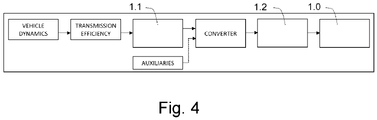
- Figure 4 depicts a characterization of a hybrid vehicle, which includes, among others, the dynamics of said hybrid vehicle.
- the dynamics of a vehicle 1 include variables and parameters such as aerodynamic force F a , gravitational force F g , inertia force F i , friction force F r , and the mass m of the vehicle itself.
- the velocity of each wheel of the vehicle, the angular acceleration, and the required torque, which is what must be provided with the power supplies 1.1 and 1.2 together with what is needed for the auxiliaries (the power demand), are obtained from these variables and equations.
- F T F a + F g + F i + F r , wherein F T is total force.
- F a 0.5 * p * A * cx * v 2 ;
- F g m * g * sin ⁇ ;
- F i m * a ;
- F r crf * m * g * cos ⁇ ;
- w wh v cyc / r wh ;
- dw wh a cyc / r wh ;
- T wh F T * r wh .
- the transmission of a vehicle 1 consists of the elements arranged between the electric motor and the axle of the corresponding wheels, and part of the generated power is lost through said transmission. It is therefore also necessary to include the efficiency of this transmission when evaluating the power demand, since these losses must be added to the power the wheels require to reach the power to be supplied (demanded power). The calculation of the efficiency of a transmission is known and not described.
- a learning technique preferably a technique based on neural networks such as the technique known as neuro-fuzzy technique, having a plurality of levels, preferably five, is applied.
- this learning technique establishes a learning strategy (interconnection pattern) which allows said output to be obtained with said inputs.
- said technique is based on "training", i.e., a set of inputs and a single output are not enough, rather it uses different values for said set of inputs with different output results, such that a learning strategy that is valid for all these iterations is established.
- the learning step S1.3 three variables are used as inputs for the learning technique used: the power demand curve of the hybrid vehicle along its assigned route and estimated in the corresponding optimization step S1.2, the state of charge curve of the battery 1.0 of said hybrid vehicle estimated in the corresponding optimization step S1.2, and a curve of the ratio of its assigned route.
- the assigned route is considered in terms of the distance remaining to complete said route (ratio of the remaining distance, preferably as a percentage).
- a predetermined power curve to be supplied by the second power supply 1.2 along said assigned route is used as the output of said learning technique.
- the second power supply 1.2 is the power supply of the hybrid vehicle not using the electrical energy stored in the battery 1.0 of said hybrid vehicle, such that with said learning technique the use of said second power supply 1.2 and the use of the battery 1.0 are linked to one another (through their state of charge curve), a learning strategy linking the use of both power supplies 1.1 and 1.2 being obtained, which allows a more efficient use to be established.
- the methodology known as backpropagation is preferably applied to obtain the interconnection pattern. This methodology involves starting from the back, i.e., starting from the end state of the input and output curves to be considered.
- an interconnection pattern, or learning strategy is obtained which, on the basis of input variables, makes the use of the power supplies 1.1 and 1.2 more efficient (based on the use of the second power supply 1.2) considering said inputs.
- said inputs take into account the state of charge of the battery 1.0 as well as the route the hybrid vehicle has to travel and the power it has to supply, so the more efficient use of the power supplies 1.1 and 1.2 also considers, for each case in particular, an efficient use of the battery 1.0 associated with the task the hybrid vehicle has to perform.
- step S1.4 of each hybrid vehicle at least the real power demand (the power the hybrid vehicle needs), the real state of charge of the battery 1.0 of said hybrid vehicle, and the remaining distance ratio of its assigned route are monitored, and from this data the real power to be supplied by the second power supply 1.2 is calculated. It therefore starts from the same input variables as those that were used in the learning technique of the learning step S1.3, with the difference that in this case these variables are a reflection of the real state of the hybrid vehicle, and the same output variable as from said learning technique is obtained, with the difference that in this case the real power to be supplied which is obtained as output is the real power to be applied.
- step S1.4 since learning is no longer required as the required learning has already been performed in the prior in the learning step S1.3, a technique is used with the learning strategy obtained in the corresponding learning step S1.3 (preferably the technique known as fuzzy logic technique). Therefore, from the real input variables, after applying said learning strategy the real electrical power to be supplied by means of the second power supply 1.2 is obtained.
- a technique is used with the learning strategy obtained in the corresponding learning step S1.3 (preferably the technique known as fuzzy logic technique). Therefore, from the real input variables, after applying said learning strategy the real electrical power to be supplied by means of the second power supply 1.2 is obtained.
- the power to be supplied by the first power supply 1.1 is calculated to enable supplying the entire power demand required for the hybrid vehicle between both power supplies 1.1 and 1.2, and finally, in said implementation step S1.4 said power supplies 1.1 and 1.2 are acted on so that each of said power supplies 1.1 and 1.2 supplies the respective calculated power.
- the electrical power to be supplied by the first power supply 1.1 is the result of subtracting the detected power demand from the obtained real power to be supplied by the second power supply 1.2.
- a strategy is thereby established which takes into account an efficient use of the battery 1.0 of each hybrid vehicle, depending on the conditions and characteristics of the hybrid vehicle itself (by means of the power to be supplied by each power supply 1.1 and 1.2), and optimal control over the use of the batteries 1.0 which allows more effectively controlling the service life of said batteries 1.0 is obtained.
- the proposed method is thus configured for considering the hybrid vehicles of the fleet individually and the entire fleet as a whole, so a fleet management which improves its efficiency and furthermore improves the total operation cost of said fleet is obtained because in addition to the service life of the batteries 1.0, it takes into account the compromise between the fuel consumption required by hybrid vehicles and said batteries 1.0.
- the following optimization step S1.2 of each hybrid vehicle uses the velocity curve associated with its assigned route (new curve if it is a new route or the same curve from before if it maintains its assigned route) and the power demand curve derived from the new calculated powers to be supplied in said adjustment step S3.4.
- Optimal balance between fuel consumption (power generation through the power supplies 1.2) and the use of the batteries 1.0 (due to the generation of power through the power supplies 1.1) of hybrid vehicles 1, i.e., an optimal balance between fuel consumption and the life of the batteries 1.0, can thus be achieved, which helps to improve total operation cost of the fleet. Therefore, with the proposed method the fleet operator maximizes profits, taking into account not only fuel consumption but also the life of the batteries 1.0 integrated in the vehicles 1 of the fleet, since the use of the batteries 1.0 is optimized at the fleet level.
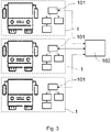
- Each vehicle 1 comprises a local control device 101, depicted in Figures 2 and 3 , where the corresponding steps are implemented (depending on whether they are hybrid vehicles or pure electric vehicles), and these local control devices 101 are thus in charge of controlling the actuation of the respective power supplies 1.1 and 1.2 in the case of hybrid vehicles, thus being communicated with said power supplies 1.1 and 1.2.
- the steps that are executed at the local level i.e., in the local control device 101, are executed dynamically and in real time (every second for example), which allows updating the action on the power supplies 1.1 and 1.2 at all times along the route of the corresponding hybrid vehicle, in the case of hybrid vehicles, according to a the conditions at the moment of said hybrid vehicles 1, and allows having control over the state of health of all the batteries 1.0 at all times.
- the fleet comprises a fleet control device 102 outside of said vehicles 1, integrated in the cloud for example, and the optimization step S1.2, the adjustment step S3.4, the decision making step S4 and the learning step S1.3 are implemented in said fleet control device 102.
- Said fleet control device 102 is communicated with the local control devices 101 of all the vehicles 1, as depicted in Figure 3 , such that an exchange of information or data between said fleet control device 102 and said local control devices 101 when required is enabled.
- the steps of the method implemented in the fleet control device 102 are executed "statically", i.e., these steps are executed only when required or when a pre-established condition is met (as in the case of the decision making step S4 described above). It can thus be periodically implemented with predetermined time periods (every month or every year, for example), or it can be caused to be activated at times when it is required, in a controlled manner.
- Implementing the steps of the local control devices 101 allows the operating conditions of the vehicle 1 to be adjusted in real time, depending on real current measurements of operating variables of said vehicle 1.
- the general conditions of the routes and hybrid vehicles do not constantly change, it is not necessary to implement the steps that are implemented in the fleet control device 102 in real time, and they can be used when required.
- they can be implemented with the change in seasons, where weather conditions vary and, therefore, the conditions hybrid vehicles 1 will have to confront vary; or they can be implemented yearly in order to perform a periodic analysis of the fleet and detect any possible anomaly or possible reassignment.
Landscapes
- Engineering & Computer Science (AREA)
- Business, Economics & Management (AREA)
- Physics & Mathematics (AREA)
- Human Resources & Organizations (AREA)
- General Physics & Mathematics (AREA)
- Radar, Positioning & Navigation (AREA)
- Remote Sensing (AREA)
- Mechanical Engineering (AREA)
- Power Engineering (AREA)
- Transportation (AREA)
- Economics (AREA)
- Strategic Management (AREA)
- Entrepreneurship & Innovation (AREA)
- Sustainable Development (AREA)
- Life Sciences & Earth Sciences (AREA)
- Sustainable Energy (AREA)
- Development Economics (AREA)
- Theoretical Computer Science (AREA)
- General Business, Economics & Management (AREA)
- Tourism & Hospitality (AREA)
- Quality & Reliability (AREA)
- Automation & Control Theory (AREA)
- Operations Research (AREA)
- Marketing (AREA)
- Game Theory and Decision Science (AREA)
- Mathematical Physics (AREA)
- Educational Administration (AREA)
- Electric Propulsion And Braking For Vehicles (AREA)
Priority Applications (1)
| Application Number | Priority Date | Filing Date | Title |
|---|---|---|---|
| EP21382101.0A EP4044145A1 (de) | 2021-02-10 | 2021-02-10 | Fahrzeugflottenverwaltungsverfahren |
Applications Claiming Priority (1)
| Application Number | Priority Date | Filing Date | Title |
|---|---|---|---|
| EP21382101.0A EP4044145A1 (de) | 2021-02-10 | 2021-02-10 | Fahrzeugflottenverwaltungsverfahren |
Publications (1)
| Publication Number | Publication Date |
|---|---|
| EP4044145A1 true EP4044145A1 (de) | 2022-08-17 |
Family
ID=74858383
Family Applications (1)
| Application Number | Title | Priority Date | Filing Date |
|---|---|---|---|
| EP21382101.0A Withdrawn EP4044145A1 (de) | 2021-02-10 | 2021-02-10 | Fahrzeugflottenverwaltungsverfahren |
Country Status (1)
| Country | Link |
|---|---|
| EP (1) | EP4044145A1 (de) |
Citations (3)
| Publication number | Priority date | Publication date | Assignee | Title |
|---|---|---|---|---|
| US20140018985A1 (en) * | 2012-07-12 | 2014-01-16 | Honda Motor Co., Ltd. | Hybrid Vehicle Fuel Efficiency Using Inverse Reinforcement Learning |
| US20150239365A1 (en) * | 2014-02-25 | 2015-08-27 | Elwha Llc | System and method for predictive control of an energy storage system for a vehicle |
| EP3492873A1 (de) * | 2017-11-30 | 2019-06-05 | Einride Ab | Batteriepackoptimierungs-transportplanungsverfahren |
-
2021
- 2021-02-10 EP EP21382101.0A patent/EP4044145A1/de not_active Withdrawn
Patent Citations (3)
| Publication number | Priority date | Publication date | Assignee | Title |
|---|---|---|---|---|
| US20140018985A1 (en) * | 2012-07-12 | 2014-01-16 | Honda Motor Co., Ltd. | Hybrid Vehicle Fuel Efficiency Using Inverse Reinforcement Learning |
| US20150239365A1 (en) * | 2014-02-25 | 2015-08-27 | Elwha Llc | System and method for predictive control of an energy storage system for a vehicle |
| EP3492873A1 (de) * | 2017-11-30 | 2019-06-05 | Einride Ab | Batteriepackoptimierungs-transportplanungsverfahren |
Non-Patent Citations (1)
| Title |
|---|
| JON ANDER LOPEZ-IBARRA ET AL., PLUG-IN HYBRID ELECTRIC BUSES TOTAL COST OF OWNERSHIP OPTIMIZATION AT FLEET LEVEL BASED ON BATTERY AGING, 30 September 2020 (2020-09-30) |
Similar Documents
| Publication | Publication Date | Title |
|---|---|---|
| Oncken et al. | Real-time model predictive powertrain control for a connected plug-in hybrid electric vehicle | |
| CN101086519B (zh) | 用于管理电能存储器件以实现目标寿命目的的方法和设备 | |
| DE102018116826B4 (de) | Fahrzeug mit modellbasierter Streckenenergievorhersage, -korrektur und -optimierung | |
| CN104859660B (zh) | 利用过去能量消耗中的变量预测电动车辆能量消耗 | |
| CN107031414B (zh) | 基于天气预报来预调节电动车辆子系统 | |
| Murphey et al. | Intelligent hybrid vehicle power control—Part II: Online intelligent energy management | |
| Salmasi | Control strategies for hybrid electric vehicles: Evolution, classification, comparison, and future trends | |
| CN100368243C (zh) | 混合动力源分配管理 | |
| CN104842996B (zh) | 一种混合动力汽车换挡方法及系统 | |
| Kazemi et al. | Predictive AECMS by utilization of intelligent transportation systems for hybrid electric vehicle powertrain control | |
| Kessels | Energy management for automotive power nets | |
| CN102991503A (zh) | 用于控制车辆的方法 | |
| Hwang et al. | Design of a range extension strategy for power decentralized fuel cell/battery electric vehicles | |
| US20150203096A1 (en) | System and Method for Controlling Battery Power Based on Predicted Battery Energy Usage | |
| CN103171559A (zh) | 分模式最优化混联式混合动力汽车能量管理方法 | |
| EP3585642B1 (de) | Verfahren und system zum ausgleichen eines batteriepacks | |
| Khodabakhshian et al. | Improving fuel economy and robustness of an improved ECMS method | |
| CN105564250A (zh) | 用于环境友好型车辆的制动控制方法和系统 | |
| Oncken et al. | Integrated predictive powertrain control for a multimode plug-in hybrid electric vehicle | |
| Park et al. | Intelligent energy management and optimization in a hybridized all-terrain vehicle with simple on–off control of the internal combustion engine | |
| CN107627864B (zh) | 一种增程式车辆的功率分配方法和控制系统 | |
| Finesso et al. | Robust equivalent consumption-based controllers for a dual-mode diesel parallel HEV | |
| Opila et al. | Performance comparison of hybrid vehicle energy management controllers on real-world drive cycle data | |
| EP4044145A1 (de) | Fahrzeugflottenverwaltungsverfahren | |
| Park et al. | Optimal supervisory control strategy for a transmission-mounted electric drive hybrid electric vehicle |
Legal Events
| Date | Code | Title | Description |
|---|---|---|---|
| PUAI | Public reference made under article 153(3) epc to a published international application that has entered the european phase |
Free format text: ORIGINAL CODE: 0009012 |
|
| STAA | Information on the status of an ep patent application or granted ep patent |
Free format text: STATUS: THE APPLICATION HAS BEEN PUBLISHED |
|
| AK | Designated contracting states |
Kind code of ref document: A1 Designated state(s): AL AT BE BG CH CY CZ DE DK EE ES FI FR GB GR HR HU IE IS IT LI LT LU LV MC MK MT NL NO PL PT RO RS SE SI SK SM TR |
|
| STAA | Information on the status of an ep patent application or granted ep patent |
Free format text: STATUS: THE APPLICATION IS DEEMED TO BE WITHDRAWN |
|
| 18D | Application deemed to be withdrawn |
Effective date: 20230218 |