EP4043913A1 - Data transmission appparatus, lidar and smart device - Google Patents
Data transmission appparatus, lidar and smart device Download PDFInfo
- Publication number
- EP4043913A1 EP4043913A1 EP20873968.0A EP20873968A EP4043913A1 EP 4043913 A1 EP4043913 A1 EP 4043913A1 EP 20873968 A EP20873968 A EP 20873968A EP 4043913 A1 EP4043913 A1 EP 4043913A1
- Authority
- EP
- European Patent Office
- Prior art keywords
- optical
- optical module
- module
- signal
- digital signal
- Prior art date
- Legal status (The legal status is an assumption and is not a legal conclusion. Google has not performed a legal analysis and makes no representation as to the accuracy of the status listed.)
- Pending
Links
- 230000005540 biological transmission Effects 0.000 title claims abstract description 175
- 230000003287 optical effect Effects 0.000 claims abstract description 827
- 230000008878 coupling Effects 0.000 claims abstract description 85
- 238000010168 coupling process Methods 0.000 claims abstract description 85
- 238000005859 coupling reaction Methods 0.000 claims abstract description 85
- 239000013307 optical fiber Substances 0.000 claims description 76
- 238000004891 communication Methods 0.000 claims description 39
- 238000000265 homogenisation Methods 0.000 claims description 25
- 230000008859 change Effects 0.000 claims description 6
- 230000002093 peripheral effect Effects 0.000 claims description 4
- 238000000034 method Methods 0.000 abstract description 8
- 238000012545 processing Methods 0.000 abstract description 5
- 238000010586 diagram Methods 0.000 description 16
- 230000008054 signal transmission Effects 0.000 description 10
- 230000000694 effects Effects 0.000 description 5
- 230000000903 blocking effect Effects 0.000 description 4
- 238000013461 design Methods 0.000 description 4
- 238000001514 detection method Methods 0.000 description 4
- 230000008569 process Effects 0.000 description 4
- 230000002441 reversible effect Effects 0.000 description 4
- 230000006870 function Effects 0.000 description 3
- 230000003993 interaction Effects 0.000 description 2
- 238000012986 modification Methods 0.000 description 2
- 230000004048 modification Effects 0.000 description 2
- 238000009792 diffusion process Methods 0.000 description 1
- 238000004806 packaging method and process Methods 0.000 description 1
- 230000008447 perception Effects 0.000 description 1
- 238000002310 reflectometry Methods 0.000 description 1
Images





Classifications
-
- G—PHYSICS
- G01—MEASURING; TESTING
- G01S—RADIO DIRECTION-FINDING; RADIO NAVIGATION; DETERMINING DISTANCE OR VELOCITY BY USE OF RADIO WAVES; LOCATING OR PRESENCE-DETECTING BY USE OF THE REFLECTION OR RERADIATION OF RADIO WAVES; ANALOGOUS ARRANGEMENTS USING OTHER WAVES
- G01S7/00—Details of systems according to groups G01S13/00, G01S15/00, G01S17/00
- G01S7/48—Details of systems according to groups G01S13/00, G01S15/00, G01S17/00 of systems according to group G01S17/00
- G01S7/481—Constructional features, e.g. arrangements of optical elements
- G01S7/4817—Constructional features, e.g. arrangements of optical elements relating to scanning
-
- B—PERFORMING OPERATIONS; TRANSPORTING
- B62—LAND VEHICLES FOR TRAVELLING OTHERWISE THAN ON RAILS
- B62D—MOTOR VEHICLES; TRAILERS
- B62D6/00—Arrangements for automatically controlling steering depending on driving conditions sensed and responded to, e.g. control circuits
-
- A—HUMAN NECESSITIES
- A01—AGRICULTURE; FORESTRY; ANIMAL HUSBANDRY; HUNTING; TRAPPING; FISHING
- A01D—HARVESTING; MOWING
- A01D34/00—Mowers; Mowing apparatus of harvesters
- A01D34/006—Control or measuring arrangements
- A01D34/008—Control or measuring arrangements for automated or remotely controlled operation
-
- G—PHYSICS
- G01—MEASURING; TESTING
- G01S—RADIO DIRECTION-FINDING; RADIO NAVIGATION; DETERMINING DISTANCE OR VELOCITY BY USE OF RADIO WAVES; LOCATING OR PRESENCE-DETECTING BY USE OF THE REFLECTION OR RERADIATION OF RADIO WAVES; ANALOGOUS ARRANGEMENTS USING OTHER WAVES
- G01S7/00—Details of systems according to groups G01S13/00, G01S15/00, G01S17/00
- G01S7/48—Details of systems according to groups G01S13/00, G01S15/00, G01S17/00 of systems according to group G01S17/00
- G01S7/481—Constructional features, e.g. arrangements of optical elements
- G01S7/4811—Constructional features, e.g. arrangements of optical elements common to transmitter and receiver
- G01S7/4813—Housing arrangements
-
- B—PERFORMING OPERATIONS; TRANSPORTING
- B62—LAND VEHICLES FOR TRAVELLING OTHERWISE THAN ON RAILS
- B62D—MOTOR VEHICLES; TRAILERS
- B62D5/00—Power-assisted or power-driven steering
- B62D5/04—Power-assisted or power-driven steering electrical, e.g. using an electric servo-motor connected to, or forming part of, the steering gear
- B62D5/0457—Power-assisted or power-driven steering electrical, e.g. using an electric servo-motor connected to, or forming part of, the steering gear characterised by control features of the drive means as such
-
- G—PHYSICS
- G02—OPTICS
- G02B—OPTICAL ELEMENTS, SYSTEMS OR APPARATUS
- G02B6/00—Light guides; Structural details of arrangements comprising light guides and other optical elements, e.g. couplings
- G02B6/24—Coupling light guides
- G02B6/36—Mechanical coupling means
- G02B6/3604—Rotary joints allowing relative rotational movement between opposing fibre or fibre bundle ends
Definitions
- the present invention relates to the technical field of a LiDAR, and particularly to a data transmission apparatus, a LiDAR, and an intelligent device.
- a LiDAR Light Detection and Ranging, LiDAR
- the LiDAR measures a distance from a target and reflectivity of the target by emitting laser pulses to the target and measuring the delay and intensity of a return pulse.
- the LiDAR generally uses a mechanical rotating apparatus to implement 360-degree spatial scanning. Each pair of apparatuses that continuously emit and receive laser pulses with a mechanical rotation is referred to as a scanning "line" of the LiDAR. Because the LiDAR is widely used in technical fields such as automatic driving and intelligent perception, the LiDAR is required to have higher spatial resolution, and hence a larger number of lines.
- a part of the LiDAR that rotates with the mechanical rotating apparatus is referred to as a radar front-end system.
- the detected laser pulses are converted into point cloud data after passing through the radar front-end system.
- a communication apparatus is required for wireless data transmission of the point cloud data.
- the inventor of this application found that the current LiDAR uses a wireless communication apparatus based on electromagnetic coupling to achieve the above-mentioned point cloud data transmission.
- the wireless communication apparatus based on electromagnetic coupling may not meet the requirement of a large number of lines. As a result, data transmission efficiency is relatively low.
- the objective of embodiments of the present invention is to provide a data transmission apparatus, a LiDAR, and an intelligent device, to improve data transmission efficiency by using light as a data transmission medium.
- An embodiment of the present invention proposes a data transmission apparatus.
- the apparatus is located in a LiDAR system, and the LiDAR system includes a rotator and a central shaft;
- the data transmission apparatus includes a first optical module, a coupling optical system, and a second optical module, the first optical module is arranged at the rotator, the second optical module is arranged at the central shaft, and the coupling optical system is arranged between the first optical module and the second optical module;
- the first optical module is configured to receive a first digital signal output by a radar front-end apparatus and convert the first digital signal into an optical signal;
- the coupling optical system includes an annular lens, and the annular lens is arranged around the central shaft and is configured to adjust a propagation direction of the optical signal output by the first optical module and transmit the optical signal to the second optical module;
- the second optical module is configured to convert the optical signal into the first digital signal and output the first digital signal to an upper application apparatus.
- An embodiment of the present invention proposes a data transmission apparatus, where the apparatus is located in a LiDAR system, and the LiDAR system includes a rotator and a central shaft; the apparatus includes: a first optical module and a second optical module; the first optical module is configured to receive a first digital signal output by a radar front-end apparatus, convert the first digital signal into an optical signal, and send the optical signal to a receiving terminal of the second optical module through an emitting terminal of the first optical module; the second optical module receives the optical signal from the first optical module by using the receiving terminal, and converts the optical signal into the first digital signal; and the emitting terminal of the first optical module and the receiving terminal of the second optical module are oppositely arranged at the central shaft.
- An embodiment of the present invention further proposes a LiDAR, including a radar front-end apparatus, an upper application apparatus, and a data transmission apparatus according to the foregoing embodiments;
- the radar front-end apparatus is configured to receive light information reflected by a target object, and convert the light information into a first digital signal;
- the data transmission apparatus is configured to transmit the first digital signal to the upper application apparatus;
- the upper application apparatus is configured to convert control information into a second digital signal; and the data transmission apparatus is further configured to transmit the second digital signal to the radar front-end apparatus.
- An embodiment of the present invention further proposes an intelligent apparatus, including the foregoing LiDAR.
- light is used as a data transmission medium for data transmission. Because of a large communication capacity, great anti-electromagnetic interference performance, and great transmission quality of optical communication, data transmission efficiency may be improved.
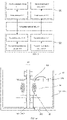
- FIG. 1 shows a schematic structural diagram of a LiDAR system provided by an embodiment of the present invention.
- the LiDAR system 100 includes a data transmission apparatus 10, a radar front-end apparatus 20, and an upper application apparatus 30.
- the radar front-end apparatus 20 is connected to one end of the data transmission apparatus 10, and the other end of the data transmission apparatus 10 is connected to the upper application apparatus 30.
- the radar front-end apparatus 20 is configured to receive light information reflected by a target object and convert the light information into a first digital signal.
- the data transmission apparatus 10 is configured to transmit the first digital signal output by the radar front-end apparatus 20 to the upper application apparatus 30.
- the upper application apparatus 30 is configured to receive the first digital signal and process the first digital signal. In the foregoing manner, detection data of the target object detected by the radar front-end apparatus 20 is transmitted to the upper application apparatus 30 through the data transmission apparatus 10 for processing, thereby obtaining object detection information.
- That the radar front-end apparatus 20 is configured to receive light information reflected by a target object and convert the light information into a first digital signal specifically includes: the radar front-end apparatus receives the light information reflected by the target object, converts the light information reflected by the target object into an electrical signal, and converts the electrical signal into the first digital signal. The radar front-end apparatus 20 transmits the first digital signal to the data transmission apparatus 10.
- the upper application apparatus 30 may be any type of terminal device with a user interaction function and a computing capability, for example, an intelligent car terminal, a drone terminal, or other terminal devices that may be mounted on an intelligent car or a drone.
- the upper application apparatus 30 is further configured to receive control instruction information and convert the received control instruction information into a second digital signal.
- the data transmission apparatus 10 is further configured to transmit the second digital signal output by the upper application apparatus 30 to the radar front-end apparatus 20, and the radar front-end apparatus 20 is further configured to receive the second digital signal and respond to the second digital signal.
- the upper application apparatus 30 transmits a user-input control instruction to the radar front-end apparatus 20 through the data transmission apparatus 10, thereby controlling the radar front-end apparatus 20.
- the data transmission apparatus 10 includes a first optical module and a second optical module.
- the first optical module 11 is communicatively connected to the radar front-end apparatus 20, and the second optical module 12 is communicatively connected to the upper application apparatus 30.
- both the first optical module and the second optical module have a transceiver module. Therefore, an uplink signal and a downlink signal may be transmitted at the same time, that is, radar ranging data and control data may be transmitted simultaneously.
- FIG. 2 shows a schematic structural diagram of a data transmission apparatus provided by an embodiment of the present invention.
- the data transmission apparatus 10 includes: a first optical module 11, a second optical module 12, and a coupling optical system 13.
- the coupling optical system 13 is arranged between the first optical module 11 and the second optical module 12.
- the first optical module 11 is communicatively connected to a radar front-end apparatus 20, and the second optical module 12 is communicatively connected to an upper application apparatus 30.
- the first optical module 11 is configured to receive a first digital signal output by the radar front-end apparatus 20 and convert the first digital signal into an optical signal.
- the coupling optical system 13 is configured to transmit the optical signal output by the first optical module 11 to the second optical module 12.
- the second optical module 12 is configured to convert the optical signal into the first digital signal and output the first digital signal to the upper application apparatus 30 for processing.
- the first optical module 11 includes a first modulation circuit 111 and a first emitter 112. One end of the first modulation circuit 111 is connected to the radar front-end apparatus 20, and the other end of the first modulation circuit 111 is connected to the first emitter 112.
- the second optical module 12 includes a second receiver 121 and a second demodulation circuit 122. One end of the second demodulation circuit 122 is connected to the second receiver 121, and the other end of the second demodulation circuit 122 is connected to the upper application apparatus 30.
- the first modulation circuit 111 is configured to modulate the first digital signal output by the radar front-end apparatus 20 into an optical signal.
- the first emitter 112 is configured to receive the optical signal output by the first modulation circuit 111 and emit the optical signal to the coupling optical system 13.
- the coupling optical system 13 transmits the optical signal to the second receiver 121.
- the second receiver 121 is configured to receive the optical signal transmitted by the coupling optical system 13.
- the second demodulation circuit 122 is configured to demodulate the optical signal output by the second receiver 121 into the first digital signal, and output the first digital signal to the upper application apparatus 30.
- the upper application apparatus 30 processes the received first digital signal to obtain ranging data.
- the apparatus 10 further includes a first communication port 141 and a second communication port 142.
- the first communication port 141 is separately connected to the first optical module 11 and the radar front-end apparatus 20.
- the first communication port 141 is separately connected to the first modulation circuit 111 and a first demodulation circuit 114.
- the second communication port 142 is separately connected to the second demodulation circuit 122 and a second modulation circuit 123.
- the first communication port 141 is configured to transmit data between the first optical module 11 and the radar front-end apparatus 20.
- the second communication port 142 is separately connected to the second optical module 12 and the upper application apparatus 30.
- the second communication port 142 is configured to transmit data between the second optical module 12 and the upper application apparatus 30.
- the data transmission apparatus 10 in the embodiment of the present invention receives the first digital signal output by the radar front-end apparatus 20 through the first optical module 11, and converts the first digital signal into the optical signal, the coupling optical system 13 transmits the optical signal from the first optical module 11 to the second optical module 12, and the second optical module 12 converts the optical signal into the first digital signal and outputs the first digital signal to the upper application apparatus 30 for processing. It may be seen that, in this embodiment, light is used as a data transmission medium for data transmission. Because of a large communication capacity, great anti-electromagnetic interference performance, and great transmission quality of optical communication, data transmission efficiency may be improved.
- the data transmission apparatus 10 is located in the LiDAR system 100.
- the LiDAR system 100 includes a rotor 15, a stator 16, and a housing 17.
- the rotor 15 and the stator 16 are received in the housing 17.
- the rotor 15 includes a rotator 151.
- the stator 16 includes a central shaft 161.
- the rotor 15 rotates around the central shaft 161, and the stator 16 is fixedly connected to the housing 17.
- the first optical module 11 is arranged at the rotor 15, and the second optical module 12 is arranged at the stator 16.
- the first optical module 11 rotates with the rotor 15, and the second optical module 12, the stator 16, and the housing 17 remain relatively stationary.
- the data transmission apparatus 10 may be an out-of-shaft design in which a coupling optical path is not on the central shaft, and relative positions of the first emitter 112 of the first optical module 11 and the second receiver 121 of the second optical module 12 change significantly when the apparatus 10 rotates.
- the first optical module 11 is arranged at the rotator 151, and the second optical module 12 is arranged on the central shaft 161.
- the data transmission apparatus 10 further includes the coupling optical system 13, and the coupling optical system 13 is arranged between the first optical module 11 and the second optical module 12.
- the coupling optical system 13 is configured to form a coupling optical path through an optical device, and transmit the optical signal output by the first optical module 11 to the second optical module 12.
- the coupling optical path may be in a direction parallel to a central shaft, or a direction perpendicular to the central shaft, or may be arranged in sections. This is not limited herein.
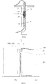
- This specification uses the coupling optical path of the out-of-shaft data transmission apparatus shown in FIG. 4a as an example to describe the following embodiments.
- the data transmission apparatus 10 further includes the first communication port 141 and the second communication port 142.
- the first communication port 141 is separately connected to the first modulation circuit 111 of the first optical module 11 and the radar front-end apparatus 20.
- the second communication port 142 is connected to the second demodulation circuit 122 of the second optical module 12 and the upper application apparatus 30.
- the coupling optical system 13 of the data transmission apparatus 10 may include an annular lens 181.
- the central shaft 161 passes through a hollow part of the annular lens 181, and the annular lens 181 and the second optical module 12 are relatively stationary.
- the rotator 151 rotates, the first optical module 11 rotates around the central shaft 161, and the central shaft 161, the housing 17, the second optical module 12, and the annular lens 181 remain relatively stationary.
- the annular lens 181 is configured to receive the optical signal emitted by the first emitter 112 of the first optical module 11 and adjust the optical signal, so that the optical signal enters the second optical module 12, and the second receiver 121 of the second optical module 12 is configured to receive the adjusted optical signal.
- the annular lens 181 may be arranged in many ways.
- the annular lens 181 is eccentrically arranged at the central shaft 161.
- the first emitter 112 emits the optical signal in a direction parallel to an optical axis A of the annular lens 181 to the annular lens 181.
- the annular lens 181 refracts the optical signal, and converges and emits the optical signal to the second receiver 121 so that the second receiver 121 receives the optical signal emitted by the first emitter 112.
- the first transmitter 112 may be provided with a collimating lens at an emitting terminal, so that the optical signal is emitted in a direction parallel to the optical axis A of the annular lens 181. It may be understood that a receiving terminal of the second receiver 121 may be arranged at an image-side focal plane of the annular lens 181. When the receiving terminal of the second receiver 121 is arranged at an image-side focal point of the annular lens 181, reception efficiency of the second receiver 121 is maximum. During rotation, the optical signal emitted by the first emitter 112 is always focused on the second receiver 121, thereby ensuring energy of a signal beam.
- the annular lens 181 is arranged at the central shaft, and an optical center of the annular lens 181 may be located on the central shaft 161.
- the first emitter 112 emits the optical signal to the annular lens 181, and the annular lens 181 receives the optical signal emitted by the first emitter 112, homogenizes the received optical signal, and then emits the received optical signal to the second receiver 121 to be received by the second receiver 121.
- the annular lens 181 in FIG. 4c may also be replaced by a diffuse uniform optical sheet.
- the first emitter 112 may be arranged on an object-side focal plane of the annular lens 181. When the first emitter 112 is arranged at the object-side focal point of the annular lens 181, the optical signal is emitted through the annular lens 181 in parallel, that is, the annular lens 181 plays a role in homogenizing the optical signal.
- the two first emitters 112 are used as an example.
- the two first emitters 112 are separately and symmetrically arranged on two sides of the central shaft 161.
- the two first emitters 112 are both configured to emit optical signals, and content of the optical signals emitted by the two first emitters 112 is the same, so as to prevent the central shaft 161 from being blocked and hence interrupting the optical signal.
- FIG. 4b and FIG. 4c the two first emitters 112 are used as an example.
- the two first emitters 112 are separately and symmetrically arranged on two sides of the central shaft 161.
- the two first emitters 112 are both configured to emit optical signals, and content of the optical signals emitted by the two first emitters 112 is the same, so as to prevent the central shaft 161 from being blocked and hence interrupting the optical signal.
- the optical signals emitted by the two first emitters 112 are emitted in parallel after passing through the annular lens 181 but are not parallel to each other. Therefore, after the optical signals emitted by the two first emitters 112 pass through the annular lens 181, beam irradiation areas overlap with each other.
- the second receiver 121 may be arranged in an area where beams overlap with each other, so as to ensure energy of a signal beam received by the second receiver 121, and reduce impact of an emitted beam being blocked by the central shaft 161.
- the annular lens 181 may be omitted.
- the coupling optical system 13 of the data transmission apparatus 10 may include a photometric optical fiber 182.
- the photometric optical fiber 182 is connected to the first emitter 112 and arranged around the central shaft 161.
- the photometric optical fiber 182 is configured to homogenize the received optical signal emitted by the first emitter 112 so that the optical signal enters the second receiver.
- an arc-shaped reflector 1821 may be arranged on a side of the photometric optical fiber 182 away from the second receiver 121.
- the arc-shaped reflector 1821 may increase light intensity of the photometric optical fiber in a receiving direction so as to ensure energy of a signal beam received by the second receiver 121.
- at least two first emitters 112 may be set, and the two first emitters 112 are separately and symmetrically arranged on two sides of the central shaft 161, so as to prevent the central shaft 161 from being blocked and hence interrupting the optical signal.
- a plurality of second receivers may alternatively be set, so as to ensure energy of the signal beam received by the second receiver.
- the plurality of first emitters 112 may alternatively be connected to the plurality of photometric optical fibers, and the plurality of photometric optical fibers simultaneously emit to form a uniform optical emitting surface in an annular belt shape.
- the optical coupling system may include 0 to N optical surfaces, where N is a natural number.
- the plurality of first emitters are arranged at equal spacing and emit the same optical signal, thereby achieving a better coverage effect.
- the second receiver may effectively receive the optical signal emitted by the first emitter.
- the optical coupling system may not be arranged.
- the data may be transmitted by directly sending the optical signal from the first optical module to the second optical module, thereby simplifying a structure.
- the data transmission apparatus 10 may also be an on-shaft design in which a coupling optical path is arranged on the central shaft. Relative positions of an emitting surface of the first optical module 11 and a receiving surface of the second optical module 12 do not change significantly when the apparatus 10 rotates.
- the data transmission apparatus 10 proposed by the embodiments of the present invention is located in the LiDAR system 100.
- the LiDAR system 100 includes the rotator 151 and the central shaft 161.
- the data transmission apparatus includes the first optical module 11 and the second optical module 12.
- the first optical module 11 is configured to receive the first digital signal output by the radar front-end apparatus 20, convert the first digital signal into the optical signal, and send the optical signal to a receiving terminal of the second optical module 12 through an emitting terminal of the first optical module 11.
- the second optical module 12 receives the optical signal from the first optical module 11 by using the receiving terminal, and converts the optical signal into the first digital signal.
- the emitting terminal of the first optical module 11 and the receiving terminal of the second optical module 12 are oppositely arranged on the central shaft 161.
- the emitting terminal of the first optical module and the receiving terminal of the second optical module are oppositely arranged on the central shaft so that when the rotator of the LiDAR and the central shaft rotate relative to each other, the emitting terminal of the first optical module and the receiving terminal of the second optical module do not move relative to each other, but only rotate relative to each other, so as to ensure that the optical signal emitted by the emitting terminal of the first optical module may be directly emitted to the receiving terminal of the second optical module, thereby greatly improving the transmission efficiency of the optical signal.
- the structure is very simple.
- the rotor 15 is the rotator.
- the rotator further includes a bearing rotor 152.
- the stator 16 is the central shaft, and the central shaft further includes a bearing stator 162.
- the bearing stator 162 and the bearing rotor 152 are received in the housing 17.
- the rotator is connected to the central shaft through a bearing.
- the rotator is connected to the bearing rotor 152.
- the central shaft is connected to the bearing statorl62.
- the emitting terminal of the first optical module is arranged on the bearing rotor, and the receiving terminal of the second optical module is arranged on the bearing stator.
- the first emitter 112 of the first optical module 11 is connected to a first optical fiber.
- An emitting terminal 1103 of the first optical fiber is fixedly arranged on the bearing rotor 152.
- the second receiver 121 of the second optical module 12 is connected to a second optical fiber.
- a receiving terminal 1203 of the second optical fiber is fixedly arranged on the bearing stator 162.
- the coupling optical system 13 is arranged between the bearing rotor 152 and the bearing stator 162.
- the emitting terminal 1103 of the first optical fiber is used as the emitting terminal of the first optical module for emitting the optical signal of the first optical module 11 to the receiving terminal 1203 of the second optical fiber, so that the optical signal is transmitted from the emitting terminal 1103 of the first optical fiber to the receiving terminal 1203 of the second optical fiber, to be received by the second optical module 12.
- the emitting terminal of the first optical fiber used as the emitting terminal of the first optical module, and the receiving terminal of the second optical fiber used as the receiving terminal of the second optical module may be arranged from the optical modules in an extending mode.
- a first modulation circuit of the first optical module and the first emitter of the first optical module may be arranged on the rotator.
- the first optical fiber used as the emitting terminal of the first optical module is independently arranged in the central shaft.
- a second modulation circuit of the second optical module and the second receiver of the second optical module may be arranged on a distal end of the fixed central shaft or on a base of the fixed central shaft.
- the second optical fiber is arranged on the central shaft, and arranged oppositely to the first optical fiber on the central shaft. In this way, only the first optical fiber and the second optical fiber need to be arranged on the central shaft to implement transmission and reception of the optical signal, and the structure is simple.
- the first optical module includes the first modulation circuit, configured to modulate the first digital signal output by the radar front-end apparatus into the optical signal; and the first emitter, connected to the first modulation circuit, configured to receive the optical signal output by the first modulation circuit, and used as the emitting terminal of the first optical module for emitting the optical signal to the second optical module.
- the second optical module includes the second receiver, used as the receiving terminal of the second optical module for receiving the optical signal, and outputting the optical signal; and the second demodulation circuit, connected to the second receiver, and configured to demodulate the optical signal output by the second receiver into the first digital signal and output the first digital signal to the upper application apparatus.
- the modulation circuit and the emitter may be separated by arranging the first emitter of the first optical module and the second receiver of the second optical module on the central shaft.
- the first modulation circuit may be separated from the first emitter in an extending mode.
- the first modulation circuit is arranged on the rotator.
- the first emitter is arranged on the foregoing bearing rotor 152.
- the second modulation circuit is arranged on the base of the central shaft in an extending mode.
- the second receiver is arranged on the bearing stator 162. This greatly saves a space occupied by the first emitter and the second receiver on the central shaft and simplifies difficulty of arrangement.
- the data transmission apparatus 10 further includes a first communication interface 141 and a second communication interface 142.
- the first communication interface 141 is connected to the first optical module 11 and the radar front-end apparatus 20 for communication between the first optical module 11 and the radar front-end apparatus 20.
- the second communication port is connected to the second optical module and the upper application apparatus 30 for communication between the second optical module 12 and the upper application apparatus 30.
- the emitting terminal 1103 of the first optical fiber is fixed to the bearing rotor 152 through a first optical fiber connector 1104.
- the receiving terminal 1203 of the second optical fiber is fixed to the bearing stator 162 through a second optical fiber connector 1204. After an optical signal emitted by the first optical fiber connector 1104 propagates a distance according to an inherent angle of the optical signal, a part of the optical signal is irradiated on the second optical fiber connector 1204 to be received by the second optical module 12.
- the coupling optical system 13 between the first emitting terminal and the second receiving terminal may include a series of optical surfaces to assist optical coupling between the emitting terminal and the receiving terminal.
- Optical fibers being the emitting terminal and the receiving terminal is used as an example for description below.
- the coupling optical system 13 of the data transmission apparatus 10 may include an optical lens group 191.
- the optical lens group 191 is configured to couple, to the receiving terminal 1203 of the second optical fiber, the optical signal emitted by the emitting terminal 1103 of the first optical fiber.
- the optical surface is arranged between the emitting terminal 1103 of the first optical fiber and the receiving terminal 1203 of the second optical fiber, to increase a receiving rate of the optical signal of the receiving terminal 1203 of the second optical fiber.
- the optical lens group 191 in the coupling optical system 13 may be a collimating lens group 192.
- the collimating lens group 192 is configured to change the optical signal emitted by the emitting terminal 1103 of the first optical fiber into a collimated optical signal, and converge the collimated optical signal to the receiving terminal 1203 of the second optical fiber.
- the collimating lens group 192 includes two collimating lens, and the collimating lens close to the emitting terminal 1103 of the first optical fiber is configured to change a diffused optical signal emitted by the emitting terminal 1103 of the first optical fiber into the collimated optical signal.
- the collimating lens away from the emitting terminal 1103 of the first optical fiber is configured to converge the collimated optical signal to the receiving terminal 1203 of the second optical fiber.
- the optical lens group 191 in the coupling optical system 13 may alternatively be a spherical lens 193.
- the spherical lens 193 is configured to converge the optical signal emitted by the emitting terminal 1103 of the first optical fiber to the receiving terminal 1203 of the second optical fiber.
- first emitters and first optical fibers there may be a plurality of first emitters and first optical fibers, and there may also be a plurality of second receivers and second optical fibers, provided that the receiving terminal 1203 of the second optical fiber may receive the optical signal emitted by the emitting terminal 1103 of the first optical fiber.
- the first emitter of the first optical module 11 is fixed on the bearing rotor
- the second receiver of the optical module 12 is fixed on the bearing stator.
- a series of optical surfaces may be inserted between beam emitting/receiving surfaces of the first optical module and the second optical module to assist optical coupling between the first optical module and the second optical module, and the number of the optical surfaces may be 0 to N. Therefore, the reception of the optical signal by the second optical module is improved.
- the data transmission apparatus may also transmit an uplink signal at the same time.
- the first optical module 11 and the second optical module 12 in an out-of-shaft solution need to transmit uplink data and downlink data at the same time
- the first emitter 112 of the first optical module 11 and a second emitter 124 of the second optical module 12 may be placed in a staggered manner, thereby avoiding interference between optical paths.
- the same coupling optical system may be shared at the same time to transmit the downlink signal and the uplink signal. It may be understood that the coupling optical system is shown in FIG. 4b, FIG. 4c , and FIG. 4d .
- the data transmission apparatus in the on-shaft solution further includes a third optical fiber and a fourth optical fiber.
- the second emitter 124 is connected to the third optical fiber
- the first receiver 113 is connected to the fourth optical fiber.
- An emitting terminal of the third optical fiber is fixed on the bearing stator 162
- a receiving terminal of the fourth optical fiber is fixed on the bearing rotor 152.
- the emitting terminal of the third optical fiber is configured to emit the optical signal of the second optical module 12 to the receiving terminal of the fourth optical fiber, so that the optical signal converted from the uplink data is transmitted from the emitting terminal of the third optical fiber to the receiving terminal of the fourth optical fiber, so as to be received by the first optical module.
- the emitting terminal of the first optical fiber and the emitting terminal of the third optical fiber may be arranged in a staggered manner.
- the coupling optical system 13 may be as shown in FIG. 5b, FIG. 5c , and FIG. 5d .
- the first optical module is fixed on the bearing rotor, and the second optical module is fixed on the bearing stator. It may be understood that to ensure that optical paths are not interfered with, the first emitter of the first optical module and the second emitter of the second optical module may be arranged in a staggered manner.
- the coupling optical system 13 of this embodiment is the same as the coupling optical system of the embodiment of FIG. 5e .
- the data transmission apparatus 10 in the embodiments of the present invention receives, by using the first optical module 11, the first digital signal output by the radar front-end apparatus 20, converts the first digital signal into the optical signal, and sends the optical signal to the receiving terminal of the second optical module through the emitting terminal of the first optical module.
- the second optical module receives the optical signal from the first optical module by using the receiving terminal, and converts the optical signal into a first digital signal.
- the emitting terminal of the first optical module and the receiving terminal of the second optical module are oppositely arranged on the central shaft. It may be seen that in this embodiment, light is used as a data transmission medium for data transmission. Transmission efficiency of the optical signal is greatly improved, and the structure is simplified by coaxially arranging the emitting terminal and the receiving terminal. In addition, because of the large communication capacity, the great anti-electromagnetic interference performance, and the great transmission quality of the optical communication, the data transmission efficiency may be improved.
- only uplink data transmission is used as an example.
- FIG. 2 shows a schematic structural diagram of a data transmission apparatus according to an embodiment of the present invention.
- the data transmission apparatus 10 includes a first optical module 11 and a second optical module 12.
- the second optical module is configured to receive a second digital signal output by an upper application apparatus, convert the second digital signal into an optical signal, and send the optical signal to a receiving terminal of the first optical module through an emitting terminal of the second optical module.
- the first optical module receives the optical signal from the second optical module by using the receiving terminal, and converts the optical signal into the second digital signal.
- the emitting terminal of the second optical module and the receiving terminal of the first optical module are oppositely arranged on a central shaft.
- the first optical module 11 further includes a first receiver 113 and a first demodulation circuit 114.
- One end of the first demodulation circuit 114 is connected to the first receiver 113, and the other end of the first demodulation circuit 114 is connected to a radar front-end apparatus 20.
- the second optical module 12 further includes a second modulation circuit 123 and a second emitter 124.
- One end of the second modulation circuit 123 is connected to the upper application apparatus 30, and the other end of the second modulation circuit 123 is connected to the second emitter 124.
- the second modulation circuit 123 is configured to receive the second digital signal sent by the upper application apparatus 30 and modulate the second digital signal into the optical signal.
- the second emitter 124 is configured to emit, to a coupling optical system 13, the optical signal output by the second modulation circuit 123.
- the coupling optical system 13 transmits the optical signal to the first receiver 113.
- the first receiver 113 is configured to receive the optical signal transmitted by the coupling optical system 13.
- the first demodulation circuit 114 is configured to demodulate the optical signal into the second digital signal and output the second digital signal to the radar front-end apparatus 20.
- the radar front-end apparatus 20 processes the received second digital signal to obtain control instruction information from the upper application apparatus 30.
- the data transmission apparatus is located in a LiDAR system.
- the LiDAR system includes a rotor (15) and a stator (16).
- the first optical module is arranged on the rotor (15), and the second optical module is arranged on the stator (16).
- an implementation of uplink data transmission includes an out-of-shaft type (as shown in FIG.4a ) and an on-shaft type (as shown in FIG.s 5a and 5e ).
- the coupling optical system is arranged the same as the data transmission apparatus for downlink data transmission.
- FIG.4b, FIG.4c , and FIG.4d for the out-of-shaft type.
- FIG.5b, FIG.5c , and FIG.5d for the on-shaft type. Details are not repeated herein.
- the same data transmission apparatus may be selected for the uplink data transmission and the downlink data transmission, as shown in FIG. 6 . It may be understood that alternatively, separate data transmission apparatuses may be used for the uplink data transmission and the downlink data transmission. It may be understood that when separate data transmission apparatuses are used for the uplink data transmission and the downlink data transmission, the two data transmission apparatuses may be the same. For example, the on-shaft solution may be used for both, and the same solution is also selected for coupling optical systems. Optionally, the two data transmission apparatuses may alternatively be different. For example, the out-of-shaft solution is selected for the uplink data transmission, and the on-shaft solution is used for the downlink signal transmission.
- the on-shaft solution is selected for the uplink data transmission
- the out-of-shaft solution is selected for the downlink data transmission.
- the two data transmission apparatuses may both select the out-of-shaft solution, but use different coupling optical systems. It may be understood that when two different data transmission apparatuses are used, interference during simultaneous transmission of uplink data and downlink data may be more effectively avoided.
- the LiDAR includes: a radar front-end apparatus configured to emit an emitted laser and receive a reflected laser, and the reflected laser is a laser, reflected back by an object in a detection area, of the emitted laser; and a rotating system arranged on one side of a laser transceiver system and detachably connected to the laser transceiver system, where the rotating system is configured to drive the radar front-end apparatus to rotate to change a path of the emitted laser.
- the LiDAR includes the radar front-end apparatus 20 and the rotating system 400.
- the radar front-end apparatus 20 is arranged at an upper end of the rotating system 400.
- the radar front-end apparatus 20 includes a laser emitting lens, a laser emitting board, a laser receiving lens and a laser receiving board.
- the rotating system 400 includes a fixing base 41 and a rotator 42.
- the radar front-end apparatus 20 is fixed on an upper part of the rotator 42.
- the rotator 42 drives the radar front-end apparatus 20 to rotate.
- the radar front-end apparatus 20 is configured to receive light information reflected by a target object and convert the light information into a first digital signal.
- a data transmission apparatus is fixed inside the rotating system 400 and configured to transmit the first digital signal to an upper application apparatus.
- the upper application apparatus is configured to convert control information into a second digital signal.
- the data transmission apparatus is further configured to transmit the second digital signal to the radar front-end apparatus 20.
- the rotating system 400 includes the fixing base 41 and the rotator 42.
- the rotator 42 and the fixing base 41 relatively rotate around a central axis of the rotator 42.
- the rotator 42 and the fixing base 41 form a hollow structure at the central axis together.
- a central shaft 411 is arranged on the fixing base41.
- the rotator 42 is rotationally connected to the fixing base 41 and rotates around a central axis of the central shaft 411.
- the rotator 42 and the central shaft 411 define a hollow structure together.
- a first optical module 441 and a second optical module 442 are both arranged in the hollow structure.
- the first optical module 441 is arranged on the rotator 42.
- the second optical module 442 is arranged on the fixing base 41.
- the rotator 42 also includes a rotating shaft 421.
- a central axis of the rotating shaft 421 coincides with the central axis of the central shaft 411.
- the rotating shaft 421 is arranged in the hollow structure and rotationally connected to an inner peripheral wall of the central shaft 411.
- the rotating shaft and the central shaft are arranged on the rotator and the fixing base, respectively, the hollow structure is formed at the central axis of the rotator and the fixing base, and the first optical module, and the second optical module are arranged in the hollow structure, thereby avoiding blocking caused during an optical transmission process, and improving a transmission efficiency of an optical signal.
- a drive apparatus such as a motor 43, is further included.
- the motor is used as an example below for description.
- the motor 43 is arranged in the hollow structure, and the rotator 42 is rotationally connected to the fixing base 41 through the motor 43.
- the motor 43 is also provided with a hollow structure.
- the rotator 42 is connected to the fixing base 41 through the motor 43, the rotator, the fixing base, and the motor also form a hollow structure at the central axis of the rotator 42.
- the motor 43 includes a stator 432, a rotor 431 coupled to the stator, and a bearing 433.
- the motor is an outer rotor motor.
- the rotor 431 is sleeved on the stator 432 so that the rotor 431 wraps the stator 432 and the bearing 433.
- the stator 432 is sleeved on an outer peripheral wall of the central shaft.
- the rotor 431 is arranged around the stator, and the rotor 431 is connected to the rotator 42.
- the bearing 433 is located between the central shaft 411 and the rotating shaft 421 to drive the rotator 42 to rotate relative to the fixing base 41.
- the first optical module and the second optical module are arranged in the hollow structure defined by the rotator and the central shaft, thereby avoiding blocking caused during the optical transmission process, and improving the transmission efficiency of the optical signal.
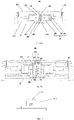
- the rotating system 400 is provided with a first optical module 441, a second optical module 442, a third optical module 443, and a fourth optical module 444 in the hollow structure, to perform uplink data transmission and downlink data transmission simultaneously.
- the first optical module 441 and the fourth optical module 444 are arranged on the rotator 42.
- the second optical module 442 and the third optical module 443 are arranged on the fixing base 41.
- the first optical module 441 and the second optical module 442 are arranged oppositely in the hollow structure.
- the third optical module 443 and the fourth optical module 444 are arranged oppositely in the hollow structure.
- the first optical module 441 is configured to receive the first digital signal output by the LiDAR front-end apparatus 20 and convert the first digital signal into an optical signal.
- the second optical module 442 is configured to convert the optical signal into the first digital signal and output the first digital signal to the upper application apparatus.
- the third optical module 443 is configured to receive the second digital signal output by the upper application apparatus, and convert the second digital signal into an optical signal.
- the fourth optical module 444 is further configured to convert the optical signal into the second digital signal and output the second digital signal to the radar front-end apparatus 20.
- the plurality of optical modules are arranged in the hollow structure formed by the rotator and the fixing base to perform uplink data transmission and downlink data transmission, thereby avoiding mutual interference during simultaneous transmission of the uplink data and the downlink data, and improving transmission reliability of the optical signal.
- the plurality of optical modules are divided into different optical signal transmission channels. It may be understood that to avoid interference between optical signals in different channels, the optical signals with different wavelengths may be transmitted in the different optical signal transmission channels. For example, in the optical signal transmission channel formed by the first optical module and the second optical module, a wavelength of emitted light is ⁇ 1 , and in the optical signal transmission channel formed by the third optical module and the fourth optical module, a wavelength of emitted light is ⁇ 2 .
- the data transmission apparatus further includes a filter structure, as shown in FIG. 8b .
- the filter structure includes: a light blocking structure 460 arranged between the first optical module 441 and the fourth optical module 444 and arranged between a connecting side of a first circuit board 451 and each of the first optical module 441 and the fourth optical module 444, and an optical filter 470 in front of a receiving terminal of the fourth optical module.
- a filter structure may be arranged on any channel to further prevent the problem of crosstalk between the different optical signal transmission channels.
- the filter structure may also be arranged on the second optical module 442 and the third optical module 443. It may be understood that when the filter structure is arranged on the second optical module 442 and the third optical module 443, the light blocking structure 460 is arranged between the second optical module 442 and the third optical module 443, and arranged between a connecting side of a second circuit board and each of the second optical module 442 and the third optical module 443.
- the optical filter 470 is arranged in front of a receiving terminal of the second optical module.
- a coupling optical system is provided in this embodiment of the present invention.
- the coupling optical system is configured to adjust the optical signal output by the first optical module 441 and then send the optical signal to the second optical module 442, and is further configured to adjust the optical signal output by the third optical module 443 and send the optical signal to the fourth optical module 444.
- the coupling optical system consists of an optical device that has 0 to N optical surfaces, and is configured to homogenize or converge the received optical signal. It may be understood that the coupling optical system may be packaged with an optical module (as shown in FIG. 9 ) or may be independently arranged in the hollow structure.
- the coupling optical system may alternatively include a part packaged with an optical module and a part independently arranged in the hollow structure. It may be understood that when the coupling optical system and the optical module are packaged together, the coupling optical system may include a homogenization module or a collimating module.
- the homogenization module may be, for example, a homogenizing sheet, a homogenization lens, or a photometric optical fiber, and the collimating module includes one or more optical lenses.
- first circuit board 451 is arranged on the rotator 42.
- the first optical module 441 and the fourth optical module 444 are arranged at a position on the circuit board 451 opposite to the hollow structure.
- the second circuit board 452 is arranged on the fixing base 41.
- the second optical module 442 and the third optical module 443 are arranged at a position on the second circuit board 452 opposite to the hollow structure.
- a third circuit board 453 is further arranged on the rotator 42.
- the third circuit board 453 is a hardware baseboard.
- the optical module and the circuit board are directly fixed together, so that a layout of an optical communication module is more compact, assembly complexity is reduced, and reliability is improved.
- the first optical module 441 and the third optical module 443 select different transmission wavelengths to send the optical signal.
- an embodiment of the present invention proposes a method for arranging an optical module in a data transmission apparatus to improve transmission reliability of an optical signal of the data transmission apparatus.
- a first optical module 441 and a fourth optical module 444 are separately arranged on two sides of a rotator relative to a central axis of a hollow structure.
- a second optical module 442 and a third optical module 443 are separately arranged on two sides of the fixing base relative to the central axis of the hollow structure.
- the second optical module 442 is located in a light spot formed on the fixing base when the first optical module 441 sends the optical signal.
- the fourth optical module 444 is located in a light spot formed on the rotator when the third optical module 443 sends the optical signal.
- a receiving terminal when the rotator rotates relative to the fixing base, a receiving terminal is always located within a light spot range of an emitting optical module. Due to the hollow structure, no optical signal blind region is generated during rotation, thereby avoiding interruption of a transmitted signal and simplifying a structure of the data transmission apparatus while ensuring data transmission quality.
- the coupling optical system is further provided in this embodiment of the present invention.
- the coupling optical system includes a first homogenization module and a second homogenization module.
- the first optical module and the first homogenization module are packaged together to homogenize the optical signal emitted by the first optical module.
- the third optical module and the second homogenization module are packaged together. Arranging the coupling optical system expands a light spot range of an emitting module, thereby making an emitted optical signal more uniform, and increasing data transmission stability.
- an optical module 4411 and a coupling optical system 4412 are packaged together, thereby increasing compactness of the system and improving reliability of the system.
- the homogenization module may be a homogenizing sheet, a homogenization lens, or a photometric optical fiber.
- a homogenization lens group may include one or more optical lenses.
- first homogenization module and the second homogenization module may use the same structure or different structures.
- first homogenization module may be a homogenizing sheet or the homogenization lens group
- second homogenization module may be a photometric optical fiber.
- the present invention also proposes another method for arranging an optical module in a data transmission apparatus, as shown in FIG. 10 .
- downlink data are ranging data, and an amount of the data is often relatively large
- uplink data are mainly control data, and configured to control a radar front-end apparatus, and an amount of the data is relatively small.
- the coupling optical system is arranged as a first collimating module and a third homogenization module.
- the first collimating module includes one or more optical lenses.
- the third homogenization module may be a homogenizing sheet, a homogenization lens group, or a photometric optical fiber.
- the first collimating module includes one or more optical lenses.
- a first optical module 441 and the first collimating module are packaged together, for example, as shown in FIG. 9 , the optical module 4411 and the coupling optical system 4412 are packaged together for a more compact structure, so as to collimate an optical signal emitted by the first optical module.
- the first optical module 441 is arranged at a position at which a central axis of the hollow structure intersects with a rotator.
- a second optical module 442 is arranged at a position at which the central axis of the hollow structure intersects with the fixing base, so that the first optical module 441 and the second optical module are located on a central axis of the rotator 42.
- the first optical module 441 and the second optical module 442 may directly face to each other without a position shift.
- the first optical module 441 sends parallel light parallel to the central axis of the hollow structure to the second optical module 442 through a collimating system. In this case, transmission efficiency of an optical signal emitted by the first optical module 441 is maximum.
- a third optical module 443 and the third homogenization module are packaged together to homogenize the optical signal emitted by the third optical module 443.
- the third optical module 443 is arranged on the fixing base on a side relative to the central axis of the hollow structure.
- a fourth optical module 444 is arranged on the rotator on a side relative to the central axis of the hollow structure. An optical signal sent by the third optical module 443 is homogenized and then emitted to the fourth optical module 444. The fourth optical module is located in a light spot formed on the rotator when the third optical module 443 sends the optical signal. In this way, transmission efficiency of the downlink data is ensured first. In addition, uplink data transmission is not affected.
- a coupling optical system includes an annular lens.
- the annular lens 460 is arranged in a hollow structure for converging incident light, and the annular lens 460 is arranged on a rotating shaft.
- the coupling optical system further includes a second collimating module and a third collimating module.
- the second and third collimating modules include one or more optical lenses.
- a first optical module 441 and the second collimating module are packaged together.
- the second collimating module is configured to collimate an optical signal emitted by the first optical module.
- a third optical module 443 and the third collimating module are packaged together.
- the third collimating module is configured to collimate an optical signal emitted by the third optical module.
- the first optical module is arranged at a position on the rotator opposite to the annular lens.
- a second optical module is arranged at a focal point of the annular lens on the fixing base.
- the first optical module emits parallel light to the annular lens, and the annular lens receives the parallel light and converges the parallel light to the second optical module.
- a fourth optical module is arranged at a position on the rotator opposite to a focal point of the annular lens.
- the third optical module is arranged at a position on the fixing base opposite to the annular lens.
- the third optical module emits parallel light to the annular lens, and the annular lens receives the parallel light and converges the parallel light to the fourth optical module.
- the first optical module 441 When performing downlink data transmission, the first optical module 441 emits parallel light to the annular lens 460. After converging the parallel light, the annular lens 460 emits the parallel light to the second optical module 442.
- the second optical module 442 is arranged at the focal point of the annular lens 460, thereby ensuring energy of a signal beam received by the second optical module 442, and implementing high-efficiency reception of the optical signal emitted by the first optical module by the second optical module.
- the rotator 42 drives the first optical module 441 to rotate when the rotator rotates relative to the fixing base 41, so that the first optical module 441 rotates relative to the annular lens 460.
- the second optical module 442 may always receive the maximum energy of the optical signal emitted by the first optical module 441.
- the annular lens 460 is arranged on the rotating shaft, the annular lens 460 and the first optical module 441 are relatively stationary, thereby more effectively converging the parallel light emitted by the first optical module 441 to the second optical module 442.
- the third optical module 443 When performing uplink data transmission, the third optical module 443 emits parallel light to the annular lens 460. After converging the parallel light, the annular lens 460 emits the parallel light to the fourth optical module 444. Because the fourth optical module 444 is arranged at the focal point of the annular lens 460, the fourth optical module 460 may receive the maximum energy of an optical signal emitted by the third optical module 443, thereby greatly improving a transmission effect of the optical signal. In addition, when the annular lens 460 is arranged on the rotating shaft, the third optical module 443 and the annular lens 460 rotate relative to each other, and the fourth optical module 444 and the annular lens 460 are relatively stationary.
- the fourth optical module 444 may always receive the maximum energy of the optical signal emitted by the third optical module 443.
- the annular lens is arranged, and the optical modules receiving the uplink data and the downlink data are all located at the focal point of the annular lens. This may ensure transmission efficiency of both uplink data transmission and downlink data transmission.
- an uplink optical signal and a downlink optical signal are transmitted in different optical paths, thereby effectively avoiding mutual interference between the optical signals and achieving an optimal transmission effect of the optical signal.
- An embodiment of the present invention further provides an intelligent sensing device.
- the intelligent sensing apparatus includes a LiDAR system.
- the LiDAR system in this embodiment has the same structure and function as the LiDAR system in the foregoing embodiment.
- the intelligent sensing device is a device that may detect an orientation and a distance of a surrounding object and make a decision based on the orientation and the distance of the surrounding object, for example, an intelligent robot, an intelligent car, or an intelligent airplane.
- the LiDAR system 100 of the intelligent sensing device is used to implement the following: A first optical module 11 receives a first digital signal output by a radar front-end apparatus 20, and converts the first digital signal into an optical signal, a coupling optical system 13 transmits an optical signal output by the first optical module 11 to a second optical module 12, and the second optical module 12 converts the optical signal into the first digital signal and outputs the first digital signal to an upper application apparatus 30 for processing. It may be seen that in this embodiment, light is used as a data transmission medium for data transmission. Because of a large communication capacity, great anti-electromagnetic interference performance, and great transmission quality of optical communication, data transmission efficiency may be improved.
- orientations or position relationships indicated by the technical terms such as “center”, “longitudinal”, “lateral”, “length”, “width”, “thickness”, “above”, “under”, “front”, “rear”, “left”, “right”, “vertical”, “horizontal”, “top”, “bottom”, “inner”, “outer”, “clockwise”, “counterclockwise”, “axial”, “radial”, and “circumferential” are based on the orientations or position relationships shown in the accompanying drawings, and are merely intended to describe the present invention and simplify the descriptions, but are not intended to indicate or imply that the indicated apparatus or element shall have a specific orientation or be formed and operated in a specific orientation, and therefore cannot be understood as a limitation on the embodiments of the present invention.
- a first feature is "above” or "under” a second feature may be that the first feature and the second feature are in direct contact, or the first feature and the second feature are in indirect contact through an intermediate medium.
- a first feature is "above”, “over”, and “on” a second feature may be that the first feature is right above or not right above the second feature, or may merely indicate that a horizontal height of the first feature is greater than that of the second feature
- That a first feature is "below”, “underneath”, and “under” a second feature may be that the first feature is right below or not right below the second feature, or may merely indicate that a horizontal height of the first feature is less than that of the second feature.
Landscapes
- Engineering & Computer Science (AREA)
- Computer Networks & Wireless Communication (AREA)
- Remote Sensing (AREA)
- Radar, Positioning & Navigation (AREA)
- General Physics & Mathematics (AREA)
- Physics & Mathematics (AREA)
- Transportation (AREA)
- Environmental Sciences (AREA)
- Life Sciences & Earth Sciences (AREA)
- Mechanical Engineering (AREA)
- Chemical & Material Sciences (AREA)
- Combustion & Propulsion (AREA)
- Optical Communication System (AREA)
- Optical Radar Systems And Details Thereof (AREA)
Abstract
Description
- The present invention relates to the technical field of a LiDAR, and particularly to a data transmission apparatus, a LiDAR, and an intelligent device.
- A LiDAR (Light Detection and Ranging, LiDAR) is a sensor that uses laser to detect and measure a distance. The LiDAR measures a distance from a target and reflectivity of the target by emitting laser pulses to the target and measuring the delay and intensity of a return pulse. The LiDAR generally uses a mechanical rotating apparatus to implement 360-degree spatial scanning. Each pair of apparatuses that continuously emit and receive laser pulses with a mechanical rotation is referred to as a scanning "line" of the LiDAR. Because the LiDAR is widely used in technical fields such as automatic driving and intelligent perception, the LiDAR is required to have higher spatial resolution, and hence a larger number of lines.
- A part of the LiDAR that rotates with the mechanical rotating apparatus is referred to as a radar front-end system. The detected laser pulses are converted into point cloud data after passing through the radar front-end system. A communication apparatus is required for wireless data transmission of the point cloud data.
- However, during a process of implementing this application, the inventor of this application found that the current LiDAR uses a wireless communication apparatus based on electromagnetic coupling to achieve the above-mentioned point cloud data transmission. However, due to a limitation of a nature of a physical transmission medium, the wireless communication apparatus based on electromagnetic coupling may not meet the requirement of a large number of lines. As a result, data transmission efficiency is relatively low.
- The objective of embodiments of the present invention is to provide a data transmission apparatus, a LiDAR, and an intelligent device, to improve data transmission efficiency by using light as a data transmission medium.
- An embodiment of the present invention proposes a data transmission apparatus. The apparatus is located in a LiDAR system, and the LiDAR system includes a rotator and a central shaft; the data transmission apparatus includes a first optical module, a coupling optical system, and a second optical module, the first optical module is arranged at the rotator, the second optical module is arranged at the central shaft, and the coupling optical system is arranged between the first optical module and the second optical module; the first optical module is configured to receive a first digital signal output by a radar front-end apparatus and convert the first digital signal into an optical signal; the coupling optical system includes an annular lens, and the annular lens is arranged around the central shaft and is configured to adjust a propagation direction of the optical signal output by the first optical module and transmit the optical signal to the second optical module; and the second optical module is configured to convert the optical signal into the first digital signal and output the first digital signal to an upper application apparatus.
- An embodiment of the present invention proposes a data transmission apparatus, where the apparatus is located in a LiDAR system, and the LiDAR system includes a rotator and a central shaft; the apparatus includes: a first optical module and a second optical module; the first optical module is configured to receive a first digital signal output by a radar front-end apparatus, convert the first digital signal into an optical signal, and send the optical signal to a receiving terminal of the second optical module through an emitting terminal of the first optical module; the second optical module receives the optical signal from the first optical module by using the receiving terminal, and converts the optical signal into the first digital signal; and the emitting terminal of the first optical module and the receiving terminal of the second optical module are oppositely arranged at the central shaft.
- An embodiment of the present invention further proposes a LiDAR, including a radar front-end apparatus, an upper application apparatus, and a data transmission apparatus according to the foregoing embodiments; the radar front-end apparatus is configured to receive light information reflected by a target object, and convert the light information into a first digital signal; the data transmission apparatus is configured to transmit the first digital signal to the upper application apparatus; the upper application apparatus is configured to convert control information into a second digital signal; and the data transmission apparatus is further configured to transmit the second digital signal to the radar front-end apparatus.
- An embodiment of the present invention further proposes an intelligent apparatus, including the foregoing LiDAR.
- In this embodiment, light is used as a data transmission medium for data transmission. Because of a large communication capacity, great anti-electromagnetic interference performance, and great transmission quality of optical communication, data transmission efficiency may be improved.
- The foregoing descriptions are only brief descriptions of the technical solutions in the embodiments of the present invention. To understand the technical means in the embodiments of the present invention more clearly so that they may be carried out according to the content of the specification, and to make the foregoing and other objectives, characteristics and advantages of the embodiments of the present invention more apparent and understandable, specific implementations of the present invention will be illustrated particularly below.
- One or more embodiments are described by using examples with reference to diagrams in accompanying drawings corresponding to the embodiments. These example descriptions do not constitute a limitation on the embodiments. Elements with the same reference numerals in the accompanying drawings indicate similar elements. Unless otherwise stated, the diagrams in the accompanying drawings do not constitute a proportional limitation.
-
FIG. 1 shows a schematic structural diagram of a LiDAR system provided by an embodiment of the present invention; -
FIG. 2 shows a schematic structural diagram of a data transmission apparatus provided by an embodiment of the present invention; -
FIG. 3 shows a schematic structural diagram of a first optical module and a second optical module ofFIG. 2 ; -
FIG. 4a to FIG. 4d show schematic structural diagrams of a data transmission apparatus with an out-of-shaft design provided by an embodiment of the present invention; -
FIG. 5a to FIG. 5e show schematic structural diagrams of a data transmission apparatus with an on-shaft design provided by an embodiment of the present invention; -
FIG. 6 shows a schematic structural diagram of a data transmission apparatus provided by another embodiment of the present invention; -
FIG. 7 shows a LiDAR provided by another embodiment of the present invention; -
FIG. 8a shows a schematic structural diagram of a data transmission apparatus provided by another embodiment of the present invention; -
FIG. 8b shows a schematic structural diagram of a data transmission apparatus provided by another embodiment of the present invention; -
FIG. 9 shows a structural diagram of packaging an optical module and a coupling optical system provided by another embodiment of the present invention; -
FIG. 10 shows an optical path diagram of a data transmission apparatus provided by another embodiment of the present invention; and -
FIG. 11 shows another optical path diagram of a data transmission apparatus provided by another embodiment of the present invention. - The following describes example embodiments of the present invention in a more detailed manner with reference to accompanying drawings. Although the accompanying drawings show the example embodiments of the present invention, it should be understood that the present invention may be implemented in various forms and should not be limited to the embodiments described herein. On the contrary, these embodiments are provided for more thoroughly understanding the present invention and entirely transferring the scope of the present invention to a person of ordinary skill in the art.
-
FIG. 1 shows a schematic structural diagram of a LiDAR system provided by an embodiment of the present invention. As shown inFIG. 1 , the LiDARsystem 100 includes adata transmission apparatus 10, a radar front-end apparatus 20, and anupper application apparatus 30. - The radar front-
end apparatus 20 is connected to one end of thedata transmission apparatus 10, and the other end of thedata transmission apparatus 10 is connected to theupper application apparatus 30. The radar front-end apparatus 20 is configured to receive light information reflected by a target object and convert the light information into a first digital signal. Thedata transmission apparatus 10 is configured to transmit the first digital signal output by the radar front-end apparatus 20 to theupper application apparatus 30. Theupper application apparatus 30 is configured to receive the first digital signal and process the first digital signal. In the foregoing manner, detection data of the target object detected by the radar front-end apparatus 20 is transmitted to theupper application apparatus 30 through thedata transmission apparatus 10 for processing, thereby obtaining object detection information. - That the radar front-
end apparatus 20 is configured to receive light information reflected by a target object and convert the light information into a first digital signal specifically includes: the radar front-end apparatus receives the light information reflected by the target object, converts the light information reflected by the target object into an electrical signal, and converts the electrical signal into the first digital signal. The radar front-end apparatus 20 transmits the first digital signal to thedata transmission apparatus 10. - The
upper application apparatus 30 may be any type of terminal device with a user interaction function and a computing capability, for example, an intelligent car terminal, a drone terminal, or other terminal devices that may be mounted on an intelligent car or a drone. - In some embodiments, the
upper application apparatus 30 is further configured to receive control instruction information and convert the received control instruction information into a second digital signal. Thedata transmission apparatus 10 is further configured to transmit the second digital signal output by theupper application apparatus 30 to the radar front-end apparatus 20, and the radar front-end apparatus 20 is further configured to receive the second digital signal and respond to the second digital signal. In the foregoing manner, theupper application apparatus 30 transmits a user-input control instruction to the radar front-end apparatus 20 through thedata transmission apparatus 10, thereby controlling the radar front-end apparatus 20. - As shown in
FIG. 2 , thedata transmission apparatus 10 includes a first optical module and a second optical module. The firstoptical module 11 is communicatively connected to the radar front-end apparatus 20, and the secondoptical module 12 is communicatively connected to theupper application apparatus 30. As shown inFIG. 3 , both the first optical module and the second optical module have a transceiver module. Therefore, an uplink signal and a downlink signal may be transmitted at the same time, that is, radar ranging data and control data may be transmitted simultaneously. - The following embodiments are described by using downlink signal transmission as an example.
-
FIG. 2 shows a schematic structural diagram of a data transmission apparatus provided by an embodiment of the present invention. As shown inFIG. 2 , thedata transmission apparatus 10 includes: a firstoptical module 11, a secondoptical module 12, and a couplingoptical system 13. - The coupling
optical system 13 is arranged between the firstoptical module 11 and the secondoptical module 12. The firstoptical module 11 is communicatively connected to a radar front-end apparatus 20, and the secondoptical module 12 is communicatively connected to anupper application apparatus 30. The firstoptical module 11 is configured to receive a first digital signal output by the radar front-end apparatus 20 and convert the first digital signal into an optical signal. The couplingoptical system 13 is configured to transmit the optical signal output by the firstoptical module 11 to the secondoptical module 12. The secondoptical module 12 is configured to convert the optical signal into the first digital signal and output the first digital signal to theupper application apparatus 30 for processing. - Specifically, referring to
FIG. 3 together, the firstoptical module 11 includes afirst modulation circuit 111 and afirst emitter 112. One end of thefirst modulation circuit 111 is connected to the radar front-end apparatus 20, and the other end of thefirst modulation circuit 111 is connected to thefirst emitter 112. The secondoptical module 12 includes asecond receiver 121 and asecond demodulation circuit 122. One end of thesecond demodulation circuit 122 is connected to thesecond receiver 121, and the other end of thesecond demodulation circuit 122 is connected to theupper application apparatus 30. In this embodiment, thefirst modulation circuit 111 is configured to modulate the first digital signal output by the radar front-end apparatus 20 into an optical signal. Thefirst emitter 112 is configured to receive the optical signal output by thefirst modulation circuit 111 and emit the optical signal to the couplingoptical system 13. The couplingoptical system 13 transmits the optical signal to thesecond receiver 121. Thesecond receiver 121 is configured to receive the optical signal transmitted by the couplingoptical system 13. Thesecond demodulation circuit 122 is configured to demodulate the optical signal output by thesecond receiver 121 into the first digital signal, and output the first digital signal to theupper application apparatus 30. Theupper application apparatus 30 processes the received first digital signal to obtain ranging data. - Referring to
FIG. 2 again, theapparatus 10 further includes afirst communication port 141 and asecond communication port 142. Thefirst communication port 141 is separately connected to the firstoptical module 11 and the radar front-end apparatus 20. Specifically, thefirst communication port 141 is separately connected to thefirst modulation circuit 111 and afirst demodulation circuit 114. Thesecond communication port 142 is separately connected to thesecond demodulation circuit 122 and asecond modulation circuit 123. Thefirst communication port 141 is configured to transmit data between the firstoptical module 11 and the radar front-end apparatus 20. Thesecond communication port 142 is separately connected to the secondoptical module 12 and theupper application apparatus 30. Thesecond communication port 142 is configured to transmit data between the secondoptical module 12 and theupper application apparatus 30. - The
data transmission apparatus 10 in the embodiment of the present invention receives the first digital signal output by the radar front-end apparatus 20 through the firstoptical module 11, and converts the first digital signal into the optical signal, the couplingoptical system 13 transmits the optical signal from the firstoptical module 11 to the secondoptical module 12, and the secondoptical module 12 converts the optical signal into the first digital signal and outputs the first digital signal to theupper application apparatus 30 for processing. It may be seen that, in this embodiment, light is used as a data transmission medium for data transmission. Because of a large communication capacity, great anti-electromagnetic interference performance, and great transmission quality of optical communication, data transmission efficiency may be improved. - Specifically, please refer to
FIG. 4a to FIG. 5e together, thedata transmission apparatus 10 is located in theLiDAR system 100. TheLiDAR system 100 includes arotor 15, astator 16, and ahousing 17. Therotor 15 and thestator 16 are received in thehousing 17. Therotor 15 includes arotator 151. Thestator 16 includes acentral shaft 161. Therotor 15 rotates around thecentral shaft 161, and thestator 16 is fixedly connected to thehousing 17. The firstoptical module 11 is arranged at therotor 15, and the secondoptical module 12 is arranged at thestator 16. The firstoptical module 11 rotates with therotor 15, and the secondoptical module 12, thestator 16, and thehousing 17 remain relatively stationary. - As shown in
FIG. 4a , thedata transmission apparatus 10 may be an out-of-shaft design in which a coupling optical path is not on the central shaft, and relative positions of thefirst emitter 112 of the firstoptical module 11 and thesecond receiver 121 of the secondoptical module 12 change significantly when theapparatus 10 rotates. The firstoptical module 11 is arranged at therotator 151, and the secondoptical module 12 is arranged on thecentral shaft 161. It may be understood that thedata transmission apparatus 10 further includes the couplingoptical system 13, and the couplingoptical system 13 is arranged between the firstoptical module 11 and the secondoptical module 12. The couplingoptical system 13 is configured to form a coupling optical path through an optical device, and transmit the optical signal output by the firstoptical module 11 to the secondoptical module 12. It may be understood that the coupling optical path may be in a direction parallel to a central shaft, or a direction perpendicular to the central shaft, or may be arranged in sections. This is not limited herein. This specification uses the coupling optical path of the out-of-shaft data transmission apparatus shown inFIG. 4a as an example to describe the following embodiments. - It may be understood that the
data transmission apparatus 10 further includes thefirst communication port 141 and thesecond communication port 142. Thefirst communication port 141 is separately connected to thefirst modulation circuit 111 of the firstoptical module 11 and the radar front-end apparatus 20. Thesecond communication port 142 is connected to thesecond demodulation circuit 122 of the secondoptical module 12 and theupper application apparatus 30. - In some other embodiments, the coupling
optical system 13 of thedata transmission apparatus 10 may include anannular lens 181. Thecentral shaft 161 passes through a hollow part of theannular lens 181, and theannular lens 181 and the secondoptical module 12 are relatively stationary. When therotator 151 rotates, the firstoptical module 11 rotates around thecentral shaft 161, and thecentral shaft 161, thehousing 17, the secondoptical module 12, and theannular lens 181 remain relatively stationary. Theannular lens 181 is configured to receive the optical signal emitted by thefirst emitter 112 of the firstoptical module 11 and adjust the optical signal, so that the optical signal enters the secondoptical module 12, and thesecond receiver 121 of the secondoptical module 12 is configured to receive the adjusted optical signal. - The
annular lens 181 may be arranged in many ways. Optionally, in some other embodiments, as shown inFIG. 4b , theannular lens 181 is eccentrically arranged at thecentral shaft 161. Thefirst emitter 112 emits the optical signal in a direction parallel to an optical axis A of theannular lens 181 to theannular lens 181. Theannular lens 181 refracts the optical signal, and converges and emits the optical signal to thesecond receiver 121 so that thesecond receiver 121 receives the optical signal emitted by thefirst emitter 112. It may be understood that thefirst transmitter 112 may be provided with a collimating lens at an emitting terminal, so that the optical signal is emitted in a direction parallel to the optical axis A of theannular lens 181. It may be understood that a receiving terminal of thesecond receiver 121 may be arranged at an image-side focal plane of theannular lens 181. When the receiving terminal of thesecond receiver 121 is arranged at an image-side focal point of theannular lens 181, reception efficiency of thesecond receiver 121 is maximum. During rotation, the optical signal emitted by thefirst emitter 112 is always focused on thesecond receiver 121, thereby ensuring energy of a signal beam. - Optionally, in some embodiments, as shown in
FIG. 4c , theannular lens 181 is arranged at the central shaft, and an optical center of theannular lens 181 may be located on thecentral shaft 161. Thefirst emitter 112 emits the optical signal to theannular lens 181, and theannular lens 181 receives the optical signal emitted by thefirst emitter 112, homogenizes the received optical signal, and then emits the received optical signal to thesecond receiver 121 to be received by thesecond receiver 121. Optionally, theannular lens 181 inFIG. 4c may also be replaced by a diffuse uniform optical sheet. It may be understood that thefirst emitter 112 may be arranged on an object-side focal plane of theannular lens 181. When thefirst emitter 112 is arranged at the object-side focal point of theannular lens 181, the optical signal is emitted through theannular lens 181 in parallel, that is, theannular lens 181 plays a role in homogenizing the optical signal. - It may be understood that to prevent light emitted by the
first emitter 112 from being blocked by thecentral shaft 161, it is optimal that at least twofirst emitters 112 are set, and the at least twofirst emitters 112 are arranged at equal spacing along thecentral shaft 161. InFIG. 4b and FIG. 4c , the twofirst emitters 112 are used as an example. The twofirst emitters 112 are separately and symmetrically arranged on two sides of thecentral shaft 161. The twofirst emitters 112 are both configured to emit optical signals, and content of the optical signals emitted by the twofirst emitters 112 is the same, so as to prevent thecentral shaft 161 from being blocked and hence interrupting the optical signal. InFIG. 4c , the optical signals emitted by the twofirst emitters 112 are emitted in parallel after passing through theannular lens 181 but are not parallel to each other. Therefore, after the optical signals emitted by the twofirst emitters 112 pass through theannular lens 181, beam irradiation areas overlap with each other. It may be understood that in some optional embodiments, thesecond receiver 121 may be arranged in an area where beams overlap with each other, so as to ensure energy of a signal beam received by thesecond receiver 121, and reduce impact of an emitted beam being blocked by thecentral shaft 161. - In some other embodiments, the
annular lens 181 may be omitted. Referring toFIG. 4d , the couplingoptical system 13 of thedata transmission apparatus 10 may include a photometricoptical fiber 182. The photometricoptical fiber 182 is connected to thefirst emitter 112 and arranged around thecentral shaft 161. The photometricoptical fiber 182 is configured to homogenize the received optical signal emitted by thefirst emitter 112 so that the optical signal enters the second receiver. Optionally, in some other embodiments, an arc-shapedreflector 1821 may be arranged on a side of the photometricoptical fiber 182 away from thesecond receiver 121. The arc-shapedreflector 1821 may increase light intensity of the photometric optical fiber in a receiving direction so as to ensure energy of a signal beam received by thesecond receiver 121. Optimally, at least twofirst emitters 112 may be set, and the twofirst emitters 112 are separately and symmetrically arranged on two sides of thecentral shaft 161, so as to prevent thecentral shaft 161 from being blocked and hence interrupting the optical signal. Optionally, in some embodiments, a plurality of second receivers may alternatively be set, so as to ensure energy of the signal beam received by the second receiver. - Optionally, as shown in the solution in
FIG. 4d , the plurality offirst emitters 112 may alternatively be connected to the plurality of photometric optical fibers, and the plurality of photometric optical fibers simultaneously emit to form a uniform optical emitting surface in an annular belt shape. - In the foregoing embodiments, by setting the annular lens or the side-emitting optical fiber in the coupling optical system, transmission quality of the optical signal is greatly improved, and a reception effect of the receiving terminal of the optical signal is improved. The annular lens may effectively converge the optical signal, so that most of the optical signal may be irradiated to the receiving terminal. By setting the side-emitting optical fiber, a diffusion effect of the optical signal is improved, so that the receiving terminal may receive the optical signal in any direction and position, improving a transmission efficiency of the optical signal. Certainly, in some embodiments, the optical coupling system may include 0 to N optical surfaces, where N is a natural number. When the system includes the plurality of first emitters, the plurality of first emitters are arranged at equal spacing and emit the same optical signal, thereby achieving a better coverage effect. The second receiver may effectively receive the optical signal emitted by the first emitter. In this case, the optical coupling system may not be arranged. The data may be transmitted by directly sending the optical signal from the first optical module to the second optical module, thereby simplifying a structure.
- In some other embodiments, the
data transmission apparatus 10 may also be an on-shaft design in which a coupling optical path is arranged on the central shaft. Relative positions of an emitting surface of the firstoptical module 11 and a receiving surface of the secondoptical module 12 do not change significantly when theapparatus 10 rotates. - The
data transmission apparatus 10 proposed by the embodiments of the present invention is located in theLiDAR system 100. TheLiDAR system 100 includes therotator 151 and thecentral shaft 161. The data transmission apparatus includes the firstoptical module 11 and the secondoptical module 12. The firstoptical module 11 is configured to receive the first digital signal output by the radar front-end apparatus 20, convert the first digital signal into the optical signal, and send the optical signal to a receiving terminal of the secondoptical module 12 through an emitting terminal of the firstoptical module 11. The secondoptical module 12 receives the optical signal from the firstoptical module 11 by using the receiving terminal, and converts the optical signal into the first digital signal. The emitting terminal of the firstoptical module 11 and the receiving terminal of the secondoptical module 12 are oppositely arranged on thecentral shaft 161. - In the embodiments of the present invention, the emitting terminal of the first optical module and the receiving terminal of the second optical module are oppositely arranged on the central shaft so that when the rotator of the LiDAR and the central shaft rotate relative to each other, the emitting terminal of the first optical module and the receiving terminal of the second optical module do not move relative to each other, but only rotate relative to each other, so as to ensure that the optical signal emitted by the emitting terminal of the first optical module may be directly emitted to the receiving terminal of the second optical module, thereby greatly improving the transmission efficiency of the optical signal. In addition, the structure is very simple.
- Referring to
FIG. 5a to FIG. 5e , therotor 15 is the rotator. The rotator further includes a bearingrotor 152. Thestator 16 is the central shaft, and the central shaft further includes a bearingstator 162. The bearingstator 162 and the bearingrotor 152 are received in thehousing 17. The rotator is connected to the central shaft through a bearing. The rotator is connected to the bearingrotor 152. The central shaft is connected to the bearing statorl62. The emitting terminal of the first optical module is arranged on the bearing rotor, and the receiving terminal of the second optical module is arranged on the bearing stator. In some optional embodiments, referring to thedata transmission apparatus 10 shown inFIG. 5a , thefirst emitter 112 of the firstoptical module 11 is connected to a first optical fiber. An emittingterminal 1103 of the first optical fiber is fixedly arranged on the bearingrotor 152. Thesecond receiver 121 of the secondoptical module 12 is connected to a second optical fiber. A receivingterminal 1203 of the second optical fiber is fixedly arranged on the bearingstator 162. The couplingoptical system 13 is arranged between the bearingrotor 152 and the bearingstator 162. The emittingterminal 1103 of the first optical fiber is used as the emitting terminal of the first optical module for emitting the optical signal of the firstoptical module 11 to the receivingterminal 1203 of the second optical fiber, so that the optical signal is transmitted from the emittingterminal 1103 of the first optical fiber to the receivingterminal 1203 of the second optical fiber, to be received by the secondoptical module 12. In this embodiment, the emitting terminal of the first optical fiber used as the emitting terminal of the first optical module, and the receiving terminal of the second optical fiber used as the receiving terminal of the second optical module may be arranged from the optical modules in an extending mode. A first modulation circuit of the first optical module and the first emitter of the first optical module may be arranged on the rotator. The first optical fiber used as the emitting terminal of the first optical module is independently arranged in the central shaft. A second modulation circuit of the second optical module and the second receiver of the second optical module may be arranged on a distal end of the fixed central shaft or on a base of the fixed central shaft. The second optical fiber is arranged on the central shaft, and arranged oppositely to the first optical fiber on the central shaft. In this way, only the first optical fiber and the second optical fiber need to be arranged on the central shaft to implement transmission and reception of the optical signal, and the structure is simple. - Similarly, in some other optional embodiments, the first optical module includes the first modulation circuit, configured to modulate the first digital signal output by the radar front-end apparatus into the optical signal; and the first emitter, connected to the first modulation circuit, configured to receive the optical signal output by the first modulation circuit, and used as the emitting terminal of the first optical module for emitting the optical signal to the second optical module. The second optical module includes the second receiver, used as the receiving terminal of the second optical module for receiving the optical signal, and outputting the optical signal; and the second demodulation circuit, connected to the second receiver, and configured to demodulate the optical signal output by the second receiver into the first digital signal and output the first digital signal to the upper application apparatus. In this embodiment, the modulation circuit and the emitter may be separated by arranging the first emitter of the first optical module and the second receiver of the second optical module on the central shaft. For example, the first modulation circuit may be separated from the first emitter in an extending mode. The first modulation circuit is arranged on the rotator. The first emitter is arranged on the foregoing
bearing rotor 152. Similarly, the second modulation circuit is arranged on the base of the central shaft in an extending mode. The second receiver is arranged on the bearingstator 162. This greatly saves a space occupied by the first emitter and the second receiver on the central shaft and simplifies difficulty of arrangement. - It may be understood that the
data transmission apparatus 10 further includes afirst communication interface 141 and asecond communication interface 142. Thefirst communication interface 141 is connected to the firstoptical module 11 and the radar front-end apparatus 20 for communication between the firstoptical module 11 and the radar front-end apparatus 20. The second communication port is connected to the second optical module and theupper application apparatus 30 for communication between the secondoptical module 12 and theupper application apparatus 30. - In some optional embodiments, please refer to the data transmission apparatus shown in
FIG. 5b , the emittingterminal 1103 of the first optical fiber is fixed to the bearingrotor 152 through a firstoptical fiber connector 1104. The receivingterminal 1203 of the second optical fiber is fixed to the bearingstator 162 through a secondoptical fiber connector 1204. After an optical signal emitted by the firstoptical fiber connector 1104 propagates a distance according to an inherent angle of the optical signal, a part of the optical signal is irradiated on the secondoptical fiber connector 1204 to be received by the secondoptical module 12. - In some optional embodiments, the coupling
optical system 13 between the first emitting terminal and the second receiving terminal may include a series of optical surfaces to assist optical coupling between the emitting terminal and the receiving terminal. Optical fibers being the emitting terminal and the receiving terminal is used as an example for description below. - In some embodiments, there may be 0 to N optical surfaces, as shown in
FIG. 5c andFIG. 5d . The couplingoptical system 13 of thedata transmission apparatus 10 may include anoptical lens group 191. Theoptical lens group 191 is configured to couple, to the receivingterminal 1203 of the second optical fiber, the optical signal emitted by the emittingterminal 1103 of the first optical fiber. The optical surface is arranged between the emittingterminal 1103 of the first optical fiber and the receivingterminal 1203 of the second optical fiber, to increase a receiving rate of the optical signal of the receivingterminal 1203 of the second optical fiber. - Optionally, in some embodiments, as shown in
FIG. 5c , theoptical lens group 191 in the couplingoptical system 13 may be acollimating lens group 192. Thecollimating lens group 192 is configured to change the optical signal emitted by the emittingterminal 1103 of the first optical fiber into a collimated optical signal, and converge the collimated optical signal to the receivingterminal 1203 of the second optical fiber. Specifically, thecollimating lens group 192 includes two collimating lens, and the collimating lens close to the emittingterminal 1103 of the first optical fiber is configured to change a diffused optical signal emitted by the emittingterminal 1103 of the first optical fiber into the collimated optical signal. The collimating lens away from the emittingterminal 1103 of the first optical fiber is configured to converge the collimated optical signal to the receivingterminal 1203 of the second optical fiber. - Optionally, in some embodiments, as shown in
FIG. 5d , theoptical lens group 191 in the couplingoptical system 13 may alternatively be aspherical lens 193. Thespherical lens 193 is configured to converge the optical signal emitted by the emittingterminal 1103 of the first optical fiber to the receivingterminal 1203 of the second optical fiber. - It should be noted that there may be a plurality of first emitters and first optical fibers, and there may also be a plurality of second receivers and second optical fibers, provided that the receiving
terminal 1203 of the second optical fiber may receive the optical signal emitted by the emittingterminal 1103 of the first optical fiber. - In other optional embodiments, please refer to the data transmission apparatus shown in
FIG. 5e , the first emitter of the firstoptical module 11 is fixed on the bearing rotor, and the second receiver of theoptical module 12 is fixed on the bearing stator. A series of optical surfaces may be inserted between beam emitting/receiving surfaces of the first optical module and the second optical module to assist optical coupling between the first optical module and the second optical module, and the number of the optical surfaces may be 0 to N. Therefore, the reception of the optical signal by the second optical module is improved. - It should be noted that the data transmission apparatus may also transmit an uplink signal at the same time. In the embodiment of the out-of-shaft data transmission apparatus shown in
FIG. 4a , if the firstoptical module 11 and the secondoptical module 12 in an out-of-shaft solution need to transmit uplink data and downlink data at the same time, thefirst emitter 112 of the firstoptical module 11 and asecond emitter 124 of the secondoptical module 12 may be placed in a staggered manner, thereby avoiding interference between optical paths. In addition, because the optical path is reversible, the same coupling optical system may be shared at the same time to transmit the downlink signal and the uplink signal. It may be understood that the coupling optical system is shown inFIG. 4b, FIG. 4c , andFIG. 4d . - It may be understood that in the embodiment of the on-shaft data transmission apparatus shown in
FIG. 5a , if the firstoptical module 11 and the secondoptical module 12 in an on-shaft solution transmit the uplink data and the downlink data simultaneously, it may be understood that the data transmission apparatus in the on-shaft solution further includes a third optical fiber and a fourth optical fiber. Thesecond emitter 124 is connected to the third optical fiber, and thefirst receiver 113 is connected to the fourth optical fiber. An emitting terminal of the third optical fiber is fixed on the bearingstator 162, and a receiving terminal of the fourth optical fiber is fixed on the bearingrotor 152. The emitting terminal of the third optical fiber is configured to emit the optical signal of the secondoptical module 12 to the receiving terminal of the fourth optical fiber, so that the optical signal converted from the uplink data is transmitted from the emitting terminal of the third optical fiber to the receiving terminal of the fourth optical fiber, so as to be received by the first optical module. It may be understood that, to ensure that optical paths are not interfered with, the emitting terminal of the first optical fiber and the emitting terminal of the third optical fiber may be arranged in a staggered manner. In addition, because the optical path is reversible, the couplingoptical system 13 may be as shown inFIG. 5b, FIG. 5c , andFIG. 5d . - It may be understood that, in the data transmission apparatus shown in
FIG. 5e , the first optical module is fixed on the bearing rotor, and the second optical module is fixed on the bearing stator. It may be understood that to ensure that optical paths are not interfered with, the first emitter of the first optical module and the second emitter of the second optical module may be arranged in a staggered manner. In addition, because the optical path is reversible, the couplingoptical system 13 of this embodiment is the same as the coupling optical system of the embodiment ofFIG. 5e . - The
data transmission apparatus 10 in the embodiments of the present invention receives, by using the firstoptical module 11, the first digital signal output by the radar front-end apparatus 20, converts the first digital signal into the optical signal, and sends the optical signal to the receiving terminal of the second optical module through the emitting terminal of the first optical module. The second optical module receives the optical signal from the first optical module by using the receiving terminal, and converts the optical signal into a first digital signal. The emitting terminal of the first optical module and the receiving terminal of the second optical module are oppositely arranged on the central shaft. It may be seen that in this embodiment, light is used as a data transmission medium for data transmission. Transmission efficiency of the optical signal is greatly improved, and the structure is simplified by coaxially arranging the emitting terminal and the receiving terminal. In addition, because of the large communication capacity, the great anti-electromagnetic interference performance, and the great transmission quality of the optical communication, the data transmission efficiency may be improved. - In some embodiments, only uplink data transmission is used as an example.
- Please refer to
FIG. 2 again,FIG. 2 shows a schematic structural diagram of a data transmission apparatus according to an embodiment of the present invention. As shown inFIG. 2 , thedata transmission apparatus 10 includes a firstoptical module 11 and a secondoptical module 12. - The second optical module is configured to receive a second digital signal output by an upper application apparatus, convert the second digital signal into an optical signal, and send the optical signal to a receiving terminal of the first optical module through an emitting terminal of the second optical module. The first optical module receives the optical signal from the second optical module by using the receiving terminal, and converts the optical signal into the second digital signal. The emitting terminal of the second optical module and the receiving terminal of the first optical module are oppositely arranged on a central shaft.
- Specifically, referring to
FIG. 3 again, the firstoptical module 11 further includes afirst receiver 113 and afirst demodulation circuit 114. One end of thefirst demodulation circuit 114 is connected to thefirst receiver 113, and the other end of thefirst demodulation circuit 114 is connected to a radar front-end apparatus 20. The secondoptical module 12 further includes asecond modulation circuit 123 and asecond emitter 124. One end of thesecond modulation circuit 123 is connected to theupper application apparatus 30, and the other end of thesecond modulation circuit 123 is connected to thesecond emitter 124. In this embodiment, thesecond modulation circuit 123 is configured to receive the second digital signal sent by theupper application apparatus 30 and modulate the second digital signal into the optical signal. Thesecond emitter 124 is configured to emit, to a couplingoptical system 13, the optical signal output by thesecond modulation circuit 123. The couplingoptical system 13 transmits the optical signal to thefirst receiver 113. Thefirst receiver 113 is configured to receive the optical signal transmitted by the couplingoptical system 13. Thefirst demodulation circuit 114 is configured to demodulate the optical signal into the second digital signal and output the second digital signal to the radar front-end apparatus 20. The radar front-end apparatus 20 processes the received second digital signal to obtain control instruction information from theupper application apparatus 30. - It may be understood that the data transmission apparatus is located in a LiDAR system. The LiDAR system includes a rotor (15) and a stator (16). The first optical module is arranged on the rotor (15), and the second optical module is arranged on the stator (16).
- It may be understood that an implementation of uplink data transmission includes an out-of-shaft type (as shown in
FIG.4a ) and an on-shaft type (as shown inFIG.s 5a and5e ). - Because the optical path is reversible, the coupling optical system is arranged the same as the data transmission apparatus for downlink data transmission. Refer to
FIG.4b, FIG.4c , andFIG.4d for the out-of-shaft type. Refer toFIG.5b, FIG.5c , andFIG.5d for the on-shaft type. Details are not repeated herein. - In some optional embodiments, it may be understood that the same data transmission apparatus may be selected for the uplink data transmission and the downlink data transmission, as shown in
FIG. 6 . It may be understood that alternatively, separate data transmission apparatuses may be used for the uplink data transmission and the downlink data transmission. It may be understood that when separate data transmission apparatuses are used for the uplink data transmission and the downlink data transmission, the two data transmission apparatuses may be the same. For example, the on-shaft solution may be used for both, and the same solution is also selected for coupling optical systems. Optionally, the two data transmission apparatuses may alternatively be different. For example, the out-of-shaft solution is selected for the uplink data transmission, and the on-shaft solution is used for the downlink signal transmission. Alternatively, the on-shaft solution is selected for the uplink data transmission, and the out-of-shaft solution is selected for the downlink data transmission. For another example, the two data transmission apparatuses may both select the out-of-shaft solution, but use different coupling optical systems. It may be understood that when two different data transmission apparatuses are used, interference during simultaneous transmission of uplink data and downlink data may be more effectively avoided. - On the basis of the foregoing embodiments of the present invention, another embodiment of the present invention provides a LiDAR. The LiDAR includes: a radar front-end apparatus configured to emit an emitted laser and receive a reflected laser, and the reflected laser is a laser, reflected back by an object in a detection area, of the emitted laser; and a rotating system arranged on one side of a laser transceiver system and detachably connected to the laser transceiver system, where the rotating system is configured to drive the radar front-end apparatus to rotate to change a path of the emitted laser. For example, as shown in
FIG. 7 , the LiDAR includes the radar front-end apparatus 20 and therotating system 400. The radar front-end apparatus 20 is arranged at an upper end of therotating system 400. The radar front-end apparatus 20 includes a laser emitting lens, a laser emitting board, a laser receiving lens and a laser receiving board. Therotating system 400, as shown inFIG. 8 , includes a fixingbase 41 and arotator 42. The radar front-end apparatus 20 is fixed on an upper part of therotator 42. Therotator 42 drives the radar front-end apparatus 20 to rotate. The radar front-end apparatus 20 is configured to receive light information reflected by a target object and convert the light information into a first digital signal. A data transmission apparatus is fixed inside therotating system 400 and configured to transmit the first digital signal to an upper application apparatus. In addition, the upper application apparatus is configured to convert control information into a second digital signal. The data transmission apparatus is further configured to transmit the second digital signal to the radar front-end apparatus 20. - As shown in
FIG. 8 , the data transmission apparatus provided by the embodiment of the present invention. Therotating system 400 includes the fixingbase 41 and therotator 42. Therotator 42 and the fixingbase 41 relatively rotate around a central axis of therotator 42. Therotator 42 and the fixingbase 41 form a hollow structure at the central axis together. - Preferably, a
central shaft 411 is arranged on the fixing base41. Therotator 42 is rotationally connected to the fixingbase 41 and rotates around a central axis of thecentral shaft 411. Therotator 42 and thecentral shaft 411 define a hollow structure together. A firstoptical module 441 and a secondoptical module 442 are both arranged in the hollow structure. The firstoptical module 441 is arranged on therotator 42. The secondoptical module 442 is arranged on the fixingbase 41. Further, therotator 42 also includes arotating shaft 421. A central axis of therotating shaft 421 coincides with the central axis of thecentral shaft 411. Therotating shaft 421 is arranged in the hollow structure and rotationally connected to an inner peripheral wall of thecentral shaft 411. - In the above manner, the rotating shaft and the central shaft are arranged on the rotator and the fixing base, respectively, the hollow structure is formed at the central axis of the rotator and the fixing base, and the first optical module, and the second optical module are arranged in the hollow structure, thereby avoiding blocking caused during an optical transmission process, and improving a transmission efficiency of an optical signal.
- As shown in
FIG. 8 , in this embodiment of this application, a drive apparatus, such as amotor 43, is further included. The motor is used as an example below for description. - The
motor 43 is arranged in the hollow structure, and therotator 42 is rotationally connected to the fixingbase 41 through themotor 43. Themotor 43 is also provided with a hollow structure. When therotator 42 is connected to the fixingbase 41 through themotor 43, the rotator, the fixing base, and the motor also form a hollow structure at the central axis of therotator 42. Themotor 43 includes astator 432, arotor 431 coupled to the stator, and abearing 433. The motor is an outer rotor motor. Therotor 431 is sleeved on thestator 432 so that therotor 431 wraps thestator 432 and thebearing 433. Thestator 432 is sleeved on an outer peripheral wall of the central shaft. Therotor 431 is arranged around the stator, and therotor 431 is connected to therotator 42. Thebearing 433 is located between thecentral shaft 411 and therotating shaft 421 to drive therotator 42 to rotate relative to the fixingbase 41. - It may be seen from the foregoing description that for the data transmission apparatus provided by this embodiment of the present invention, the first optical module and the second optical module are arranged in the hollow structure defined by the rotator and the central shaft, thereby avoiding blocking caused during the optical transmission process, and improving the transmission efficiency of the optical signal.
- To implement data transmission of the LiDAR, the
rotating system 400 provided by this embodiment of the present invention is provided with a firstoptical module 441, a secondoptical module 442, a thirdoptical module 443, and a fourthoptical module 444 in the hollow structure, to perform uplink data transmission and downlink data transmission simultaneously. As shown inFIG. 8 , the firstoptical module 441 and the fourthoptical module 444 are arranged on therotator 42. The secondoptical module 442 and the thirdoptical module 443 are arranged on the fixingbase 41. The firstoptical module 441 and the secondoptical module 442 are arranged oppositely in the hollow structure. The thirdoptical module 443 and the fourthoptical module 444 are arranged oppositely in the hollow structure. The firstoptical module 441 is configured to receive the first digital signal output by the LiDAR front-end apparatus 20 and convert the first digital signal into an optical signal. The secondoptical module 442 is configured to convert the optical signal into the first digital signal and output the first digital signal to the upper application apparatus. The thirdoptical module 443 is configured to receive the second digital signal output by the upper application apparatus, and convert the second digital signal into an optical signal. The fourthoptical module 444 is further configured to convert the optical signal into the second digital signal and output the second digital signal to the radar front-end apparatus 20. - In this embodiment of the present invention, the plurality of optical modules are arranged in the hollow structure formed by the rotator and the fixing base to perform uplink data transmission and downlink data transmission, thereby avoiding mutual interference during simultaneous transmission of the uplink data and the downlink data, and improving transmission reliability of the optical signal.
- Further, to improve the transmission efficiency of the optical signal, in some other embodiments of the present invention, the plurality of optical modules are divided into different optical signal transmission channels. It may be understood that to avoid interference between optical signals in different channels, the optical signals with different wavelengths may be transmitted in the different optical signal transmission channels. For example, in the optical signal transmission channel formed by the first optical module and the second optical module, a wavelength of emitted light is λ1, and in the optical signal transmission channel formed by the third optical module and the fourth optical module, a wavelength of emitted light is λ2.
- Further, to further prevent a problem of crosstalk of the optical signals between the different optical signal transmission channels, in other embodiments of the present invention, the data transmission apparatus further includes a filter structure, as shown in
FIG. 8b . The filter structure includes: alight blocking structure 460 arranged between the firstoptical module 441 and the fourthoptical module 444 and arranged between a connecting side of afirst circuit board 451 and each of the firstoptical module 441 and the fourthoptical module 444, and anoptical filter 470 in front of a receiving terminal of the fourth optical module. - It may be understood that when the data transmission apparatus includes the two optical signal transmission channels, a filter structure may be arranged on any channel to further prevent the problem of crosstalk between the different optical signal transmission channels.
- For example, the filter structure may also be arranged on the second
optical module 442 and the thirdoptical module 443. It may be understood that when the filter structure is arranged on the secondoptical module 442 and the thirdoptical module 443, thelight blocking structure 460 is arranged between the secondoptical module 442 and the thirdoptical module 443, and arranged between a connecting side of a second circuit board and each of the secondoptical module 442 and the thirdoptical module 443. Theoptical filter 470 is arranged in front of a receiving terminal of the second optical module. - Further, to improve the transmission efficiency of the optical signal, a coupling optical system is provided in this embodiment of the present invention. The coupling optical system is configured to adjust the optical signal output by the first
optical module 441 and then send the optical signal to the secondoptical module 442, and is further configured to adjust the optical signal output by the thirdoptical module 443 and send the optical signal to the fourthoptical module 444. The coupling optical system consists of an optical device that has 0 to N optical surfaces, and is configured to homogenize or converge the received optical signal. It may be understood that the coupling optical system may be packaged with an optical module (as shown inFIG. 9 ) or may be independently arranged in the hollow structure. It may be understood that the coupling optical system may alternatively include a part packaged with an optical module and a part independently arranged in the hollow structure. It may be understood that when the coupling optical system and the optical module are packaged together, the coupling optical system may include a homogenization module or a collimating module. The homogenization module may be, for example, a homogenizing sheet, a homogenization lens, or a photometric optical fiber, and the collimating module includes one or more optical lenses. - Further, the
first circuit board 451 is arranged on therotator 42. The firstoptical module 441 and the fourthoptical module 444 are arranged at a position on thecircuit board 451 opposite to the hollow structure. Thesecond circuit board 452 is arranged on the fixingbase 41. The secondoptical module 442 and the thirdoptical module 443 are arranged at a position on thesecond circuit board 452 opposite to the hollow structure. Athird circuit board 453 is further arranged on therotator 42. Thethird circuit board 453 is a hardware baseboard. In this embodiment of the present invention, the optical module and the circuit board are directly fixed together, so that a layout of an optical communication module is more compact, assembly complexity is reduced, and reliability is improved. - In addition, to better implement simultaneous transmission of the uplink data and the downlink data and avoid transmission interference, the first
optical module 441 and the thirdoptical module 443 select different transmission wavelengths to send the optical signal. - Furthermore, an embodiment of the present invention proposes a method for arranging an optical module in a data transmission apparatus to improve transmission reliability of an optical signal of the data transmission apparatus. As shown in
FIG. 8 , in this embodiment of the present invention, a firstoptical module 441 and a fourthoptical module 444 are separately arranged on two sides of a rotator relative to a central axis of a hollow structure. A secondoptical module 442 and a thirdoptical module 443 are separately arranged on two sides of the fixing base relative to the central axis of the hollow structure. The secondoptical module 442 is located in a light spot formed on the fixing base when the firstoptical module 441 sends the optical signal. The fourthoptical module 444 is located in a light spot formed on the rotator when the thirdoptical module 443 sends the optical signal. In this embodiment of the present invention, when the rotator rotates relative to the fixing base, a receiving terminal is always located within a light spot range of an emitting optical module. Due to the hollow structure, no optical signal blind region is generated during rotation, thereby avoiding interruption of a transmitted signal and simplifying a structure of the data transmission apparatus while ensuring data transmission quality. Further, to improve the transmission efficiency of the optical signal, the coupling optical system is further provided in this embodiment of the present invention. The coupling optical system includes a first homogenization module and a second homogenization module. For example, the first optical module and the first homogenization module are packaged together to homogenize the optical signal emitted by the first optical module. The third optical module and the second homogenization module are packaged together. Arranging the coupling optical system expands a light spot range of an emitting module, thereby making an emitted optical signal more uniform, and increasing data transmission stability. In addition, as shown inFIG. 9 , anoptical module 4411 and a couplingoptical system 4412 are packaged together, thereby increasing compactness of the system and improving reliability of the system. The homogenization module may be a homogenizing sheet, a homogenization lens, or a photometric optical fiber. A homogenization lens group may include one or more optical lenses. It may be understood that the first homogenization module and the second homogenization module may use the same structure or different structures. For example, the first homogenization module may be a homogenizing sheet or the homogenization lens group, and the second homogenization module may be a photometric optical fiber. - In another optional embodiment, the present invention also proposes another method for arranging an optical module in a data transmission apparatus, as shown in
FIG. 10 . Because in an actual application of a LiDAR, downlink data are ranging data, and an amount of the data is often relatively large, while uplink data are mainly control data, and configured to control a radar front-end apparatus, and an amount of the data is relatively small. To improve a transmission efficiency of the downlink data, the coupling optical system is arranged as a first collimating module and a third homogenization module. The first collimating module includes one or more optical lenses. The third homogenization module may be a homogenizing sheet, a homogenization lens group, or a photometric optical fiber. The first collimating module includes one or more optical lenses. In this embodiment of this application, a firstoptical module 441 and the first collimating module are packaged together, for example, as shown inFIG. 9 , theoptical module 4411 and the couplingoptical system 4412 are packaged together for a more compact structure, so as to collimate an optical signal emitted by the first optical module. In addition, the firstoptical module 441 is arranged at a position at which a central axis of the hollow structure intersects with a rotator. A secondoptical module 442 is arranged at a position at which the central axis of the hollow structure intersects with the fixing base, so that the firstoptical module 441 and the second optical module are located on a central axis of therotator 42. When therotator 42 and the fixingshaft 41 rotate relative to each other, the firstoptical module 441 and the secondoptical module 442 may directly face to each other without a position shift. In addition, the firstoptical module 441 sends parallel light parallel to the central axis of the hollow structure to the secondoptical module 442 through a collimating system. In this case, transmission efficiency of an optical signal emitted by the firstoptical module 441 is maximum. In addition, to ensure uplink signal transmission, a thirdoptical module 443 and the third homogenization module are packaged together to homogenize the optical signal emitted by the thirdoptical module 443. The thirdoptical module 443 is arranged on the fixing base on a side relative to the central axis of the hollow structure. A fourthoptical module 444 is arranged on the rotator on a side relative to the central axis of the hollow structure. An optical signal sent by the thirdoptical module 443 is homogenized and then emitted to the fourthoptical module 444. The fourth optical module is located in a light spot formed on the rotator when the thirdoptical module 443 sends the optical signal. In this way, transmission efficiency of the downlink data is ensured first. In addition, uplink data transmission is not affected. - In another optional embodiment, the present invention further proposes a method for arranging a third optical module in a data transmission apparatus. As shown in
FIG. 11 , a coupling optical system includes an annular lens. Theannular lens 460 is arranged in a hollow structure for converging incident light, and theannular lens 460 is arranged on a rotating shaft. In this embodiment of the present invention, the coupling optical system further includes a second collimating module and a third collimating module. The second and third collimating modules include one or more optical lenses. A firstoptical module 441 and the second collimating module are packaged together. The second collimating module is configured to collimate an optical signal emitted by the first optical module. A thirdoptical module 443 and the third collimating module are packaged together. The third collimating module is configured to collimate an optical signal emitted by the third optical module. The first optical module is arranged at a position on the rotator opposite to the annular lens. A second optical module is arranged at a focal point of the annular lens on the fixing base. The first optical module emits parallel light to the annular lens, and the annular lens receives the parallel light and converges the parallel light to the second optical module. A fourth optical module is arranged at a position on the rotator opposite to a focal point of the annular lens. The third optical module is arranged at a position on the fixing base opposite to the annular lens. The third optical module emits parallel light to the annular lens, and the annular lens receives the parallel light and converges the parallel light to the fourth optical module. - When performing downlink data transmission, the first
optical module 441 emits parallel light to theannular lens 460. After converging the parallel light, theannular lens 460 emits the parallel light to the secondoptical module 442. The secondoptical module 442 is arranged at the focal point of theannular lens 460, thereby ensuring energy of a signal beam received by the secondoptical module 442, and implementing high-efficiency reception of the optical signal emitted by the first optical module by the second optical module. In addition, when theannular lens 460 is arranged on the central shaft, therotator 42 drives the firstoptical module 441 to rotate when the rotator rotates relative to the fixingbase 41, so that the firstoptical module 441 rotates relative to theannular lens 460. Because the firstoptical module 441 emits the parallel light to theannular lens 460, and the secondoptical module 442 is located at the focal point of theannular lens 460, the secondoptical module 442 may always receive the maximum energy of the optical signal emitted by the firstoptical module 441. When theannular lens 460 is arranged on the rotating shaft, theannular lens 460 and the firstoptical module 441 are relatively stationary, thereby more effectively converging the parallel light emitted by the firstoptical module 441 to the secondoptical module 442. - When performing uplink data transmission, the third
optical module 443 emits parallel light to theannular lens 460. After converging the parallel light, theannular lens 460 emits the parallel light to the fourthoptical module 444. Because the fourthoptical module 444 is arranged at the focal point of theannular lens 460, the fourthoptical module 460 may receive the maximum energy of an optical signal emitted by the thirdoptical module 443, thereby greatly improving a transmission effect of the optical signal. In addition, when theannular lens 460 is arranged on the rotating shaft, the thirdoptical module 443 and theannular lens 460 rotate relative to each other, and the fourthoptical module 444 and theannular lens 460 are relatively stationary. Because the thirdoptical module 443 emits the parallel light to theannular lens 460, and the fourthoptical module 444 is located at the focal point of theannular lens 460, the fourthoptical module 444 may always receive the maximum energy of the optical signal emitted by the thirdoptical module 443. - It may be seen from the foregoing embodiments that the annular lens is arranged, and the optical modules receiving the uplink data and the downlink data are all located at the focal point of the annular lens. This may ensure transmission efficiency of both uplink data transmission and downlink data transmission. In addition, an uplink optical signal and a downlink optical signal are transmitted in different optical paths, thereby effectively avoiding mutual interference between the optical signals and achieving an optimal transmission effect of the optical signal.
- An embodiment of the present invention further provides an intelligent sensing device. The intelligent sensing apparatus includes a LiDAR system. The LiDAR system in this embodiment has the same structure and function as the LiDAR system in the foregoing embodiment. For the specific structure and function of the LiDAR system, please refer to the foregoing embodiment. Details are not repeated herein.
- The intelligent sensing device is a device that may detect an orientation and a distance of a surrounding object and make a decision based on the orientation and the distance of the surrounding object, for example, an intelligent robot, an intelligent car, or an intelligent airplane.
- It should be noted that unless otherwise specified, the technical or scientific terms used in the embodiments of the present invention should have general meanings understood by a person of ordinary skill in the art to which the embodiments of the present invention belong.
- In this embodiment of the present invention, the
LiDAR system 100 of the intelligent sensing device is used to implement the following: A firstoptical module 11 receives a first digital signal output by a radar front-end apparatus 20, and converts the first digital signal into an optical signal, a couplingoptical system 13 transmits an optical signal output by the firstoptical module 11 to a secondoptical module 12, and the secondoptical module 12 converts the optical signal into the first digital signal and outputs the first digital signal to anupper application apparatus 30 for processing. It may be seen that in this embodiment, light is used as a data transmission medium for data transmission. Because of a large communication capacity, great anti-electromagnetic interference performance, and great transmission quality of optical communication, data transmission efficiency may be improved. - In the description of a novel embodiment of this implementation, orientations or position relationships indicated by the technical terms such as "center", "longitudinal", "lateral", "length", "width", "thickness", "above", "under", "front", "rear", "left", "right", "vertical", "horizontal", "top", "bottom", "inner", "outer", "clockwise", "counterclockwise", "axial", "radial", and "circumferential" are based on the orientations or position relationships shown in the accompanying drawings, and are merely intended to describe the present invention and simplify the descriptions, but are not intended to indicate or imply that the indicated apparatus or element shall have a specific orientation or be formed and operated in a specific orientation, and therefore cannot be understood as a limitation on the embodiments of the present invention.
- In addition, the technical terms such as "first" and "second are merely intended for a purpose of description, and shall not be understood as an indication or implication of relative importance or implicit indication of a quantity of indicated technical features. In the description of the embodiments of the present invention, "a plurality of" means two or more, unless otherwise specifically defined.
- In the description of the novel embodiment of this implementation, unless otherwise clearly specified and limited, the technical terms such as "mounting", "connected", "connection", and "fixing" shall be understood in a general sense. For example, these technical terms may be a fixed connection, a detachable connection, or an integrated connection; or may be a mechanical connection or an electrical connection; or may be a direct connection, an indirect connection by using an intermediate medium, or an internal communication of two elements or an interaction of two elements. A person of ordinary skill in the art may understand specific meanings of the foregoing terms in the embodiments of the present invention according to a specific situation.
- In the description of the embodiments of the present invention, unless otherwise clearly specified and defined, that a first feature is "above" or "under" a second feature may be that the first feature and the second feature are in direct contact, or the first feature and the second feature are in indirect contact through an intermediate medium. Moreover, that a first feature is "above", "over", and "on" a second feature may be that the first feature is right above or not right above the second feature, or may merely indicate that a horizontal height of the first feature is greater than that of the second feature That a first feature is "below", "underneath", and "under" a second feature may be that the first feature is right below or not right below the second feature, or may merely indicate that a horizontal height of the first feature is less than that of the second feature.
- Finally, it should be noted that the foregoing embodiments are intended for describing instead of limiting the technical solutions of the present invention. Although the present invention is described in detail with reference to the foregoing embodiments, persons of ordinary skill in the art should understand that they may still make modifications to the technical solutions described in the foregoing embodiments or make equivalent replacements to some or all technical features thereof, without departing from the scope of the technical solutions. All these modifications or replacements shall fall within the scope of the claims and specification of the present invention. Particularly, the technical features mentioned in all embodiments may be combined in any manner, provided that no structural conflict occurs. The present invention is not limited to the specific embodiments disclosed in this specification, but includes all technical solutions that fall within the scope of the claims.
Claims (42)
- A data transmission apparatus, wherein the apparatus is located in a LiDAR system, and the LiDAR system comprises a rotator and a central shaft;the data transmission apparatus comprises a first optical module, a coupling optical system, and a second optical module, the first optical module is arranged on the rotator, the second optical module is arranged on the central shaft, and the coupling optical system is arranged between the first optical module and the second optical module;the first optical module is configured to receive a first digital signal output by a radar front-end apparatus, and convert the first digital signal into an optical signal;the coupling optical system comprises an annular lens, and the annular lens is arranged around the central shaft, and configured to adjust a propagation direction of the optical signal output by the first optical module, and transmit the optical signal to the second optical module; andthe second optical module is configured to convert the optical signal into the first digital signal and output the first digital signal to an upper application apparatus.
- The apparatus according to claim 1, whereinthe first optical module comprises:a first modulation circuit, configured to modulate the first digital signal output by the radar front-end apparatus into the optical signal, anda first emitter, connected to the first modulation circuit, and configured to receive the optical signal output by the first modulation circuit, and emit the optical signal to the coupling optical system; andthe second optical module comprises:a second receiver, configured to receive the optical signal transmitted by the coupling optical system, anda second demodulation circuit, connected to the second receiver, and configured to demodulate the optical signal output by the second receiver into the first digital signal and output the first digital signal to the upper application apparatus.
- The apparatus according to claim 2, wherein the annular lens is eccentrically arranged on the central shaft; and
the annular lens is configured to receive a parallel optical signal emitted by the first emitter, and converge and emit the received optical signal to the second receiver. - The apparatus according to claim 2, wherein the annular lens is arranged on the central shaft, and an optical center of the annular lens is located on the central shaft; and
the annular lens is configured to receive the optical signal emitted by the first emitter, and homogenize and emit the received optical signal to the second receiver. - The apparatus according to claim 2, wherein there are at least two first emitters, and the at least two first emitters are arranged at equal spacing along the central shaft.
- The apparatus according to any one of claims 2 to 5, wherein the apparatus further comprises a first communication port and a second communication port, the first communication port is separately connected to the first modulation circuit and the radar front-end apparatus, and the second communication port is connected to the second demodulation circuit and the upper application apparatus.
- The apparatus according to any one of claims 1 to 5, wherein the second optical module is further configured to receive a second digital signal output by the upper application apparatus, and convert the second digital signal into an optical signal; the coupling optical system is further configured to adjust the optical signal output by the second optical module, and transmit the adjusted optical signal to the first optical module; and the first optical module is further configured to convert the optical signal transmitted by the coupling optical system into the second digital signal and output the second digital signal.
- A data transmission apparatus, wherein the apparatus is located in a LiDAR system, and the LiDAR system comprises a rotator and a central shaft;the data transmission apparatus comprises a first optical module, a coupling optical system, and a second optical module, the first optical module is arranged on the central shaft, the second optical module is arranged on the rotator, and the coupling optical system is arranged between the first optical module and the second optical module;the second optical module is configured to receive a second digital signal output by an upper application apparatus, and convert the second digital signal into an optical signal;the coupling optical system comprises an annular lens, and the annular lens is arranged around the central shaft, and configured to adjust a propagation direction of the optical signal output by the second optical module, and transmit the optical signal to the first optical module; andthe first optical module is configured to convert the optical signal into the second digital signal and output the second digital signal.
- The apparatus according to claim 8, whereinthe second optical module comprises:a second modulation circuit, configured to modulate the second digital signal output by the upper application apparatus into the optical signal, anda second emitter, connected to the second modulation circuit, and configured to receive the optical signal output by the second modulation circuit and emit the optical signal to the coupling optical system; andthe first optical module comprises:a first receiver, configured to receive the optical signal transmitted by the coupling optical system, anda first demodulation circuit, connected to the first receiver, and configured to demodulate the optical signal output by the first receiver into the second digital signal and output the second digital signal to a radar front-end apparatus.
- A data transmission apparatus, wherein the apparatus is located in a LiDAR system, and the LiDAR system comprises a rotator and a central shaft;the apparatus comprises a first optical module and a second optical module;the first optical module is configured to receive a first digital signal output by a radar front-end apparatus, convert the first digital signal into an optical signal, and send the optical signal to a receiving terminal of the second optical module through an emitting terminal of the first optical module;the second optical module receives the optical signal from the first optical module by using the receiving terminal, and converts the optical signal into the first digital signal; andthe emitting terminal of the first optical module and the receiving terminal of the second optical module are oppositely arranged on the central shaft.
- The apparatus according to claim 10, whereinthe first optical module comprises a first modulation circuit, configured to modulate the first digital signal output by the radar front-end apparatus into the optical signal, anda first emitter, connected to the first modulation circuit, configured to receive the optical signal output by the first modulation circuit, and used as the emitting terminal of the first optical module for emitting the optical signal to the second optical module; andthe second optical module comprises a second receiver, used as the receiving terminal of the second optical module for receiving the optical signal and output the optical signal, anda second demodulation circuit, connected to the second receiver, and configured to demodulate the optical signal output by the second receiver into the first digital signal and output the first digital signal to an upper application apparatus.
- The apparatus according to claim 10, wherein the apparatus further comprises a first optical fiber and a second optical fiber;the first optical fiber is connected to the first optical module, and an emitting terminal of the first optical fiber is used as the emitting terminal of the first optical module for sending the optical signal of the first optical module to the second optical module; andthe second optical fiber is connected to the second optical module, and a receiving terminal of the second optical fiber is used as the receiving terminal of the second optical module for receiving the optical signal.
- The apparatus according to any one of claims 10 to 12, wherein the rotator is connected to the central shaft through a bearing, the rotator is connected to a bearing rotor, the central shaft is connected to a bearing stator, the emitting terminal of the first optical module is arranged on the bearing rotor, and the receiving terminal of the second optical module is arranged on the bearing stator.
- The apparatus according to claim 13, wherein the apparatus further comprises a coupling optical system, the coupling optical system is arranged between the emitting terminal of the first optical module and the receiving terminal of the second optical module, an optical lens group is provided on the coupling optical system, and the optical lens group is configured to couple the optical signal emitted by the emitting terminal of the first optical module to the receiving terminal of the second optical module.
- The apparatus according to claim 14, wherein the optical lens group is a collimating lens group, and the collimating lens group is configured to change the optical signal emitted by the emitting terminal of the first optical module into a collimated optical signal, and converge the collimated optical signal to the receiving terminal of the second optical module.
- The apparatus according to claim 14, wherein the optical lens group is a spherical lens, and the spherical lens is configured to converge the optical signal emitted by the emitting terminal of the first optical module to the receiving terminal of the second optical module.
- The apparatus according to claim 11, wherein the apparatus further comprises a first communication port and a second communication port, the first communication port is separately connected to the first modulation circuit and the radar front-end apparatus, and the second communication port is connected to the second demodulation circuit and the upper application apparatus.
- The apparatus according to claim 10, wherein the second optical module is further configured to receive a second digital signal output by the upper application apparatus, convert the second digital signal into an optical signal, and emit the optical signal through the emitting terminal of the second optical module; and the first optical module is further configured to receive the optical signal through the receiving terminal of the first optical module, convert the optical signal into the second digital signal, and output the second digital signal.
- A data transmission apparatus, wherein the apparatus is located in a LiDAR system, and the LiDAR system comprises a rotator and a central shaft;the apparatus comprises a first optical module and a second optical module;the second optical module is configured to receive a second digital signal output by an upper application apparatus, convert the second digital signal into an optical signal, and send the optical signal to a receiving terminal of the first optical module through an emitting terminal of the second optical module;the first optical module receives the optical signal from the second optical module by using the receiving terminal, and converts the optical signal into the second digital signal; andthe emitting terminal of the second optical module and the receiving terminal of the first optical module are oppositely arranged on the central shaft.
- The apparatus according to claim 19, whereinthe second optical module comprises a second modulation circuit configured to modulate the second digital signal output by the upper application apparatus into the optical signal, anda second emitter, connected to the second modulation circuit, configured to receive the optical signal output by the second modulation circuit, and used as the emitting terminal of the second optical module for emitting the optical signal to the first optical module; andthe first optical module comprises: a first receiver, used as the receiving terminal of the first optical module for receiving the optical signal, and output the optical signal, anda first demodulation circuit, connected to the first receiver, and configured to demodulate the optical signal output by the first receiver into the second digital signal and output the second digital signal to a radar front-end apparatus.
- The apparatus according to claim 19, wherein the apparatus further comprises a third optical fiber and a fourth optical fiber;the third optical fiber is connected to the second optical module, and an emitting terminal of the third optical fiber is used as the emitting terminal of the second optical module for sending the optical signal of the second optical module to the first optical module; andthe fourth optical fiber is connected to the first optical module, and a receiving terminal of the fourth optical fiber is used as the receiving terminal of the first optical module for receiving the optical signal.
- The apparatus according to any one of claims 19 to 21, wherein the rotator is connected to the central shaft through a bearing, the rotator is connected to a bearing rotor, the central shaft is connected to a bearing stator, the receiving terminal of the first optical module is arranged on the bearing rotor, and the emitting terminal of the second optical module is arranged on the bearing stator.
- A data transmission apparatus, wherein the apparatus is applied to a LiDAR system;the LiDAR system comprises a rotator and a central shaft;the apparatus comprises a first optical module and a second optical module;the first optical module is configured to receive a first digital signal output by a radar front-end apparatus, convert the first digital signal into an optical signal, and send the optical signal to a receiving terminal of the optical module through an emitting terminal of the first optical module;the second optical module receives the optical signal from the first optical module by using the receiving terminal, and converts the optical signal into the first digital signal; andthe emitting terminal of the first optical module and the receiving terminal of the second optical module are oppositely arranged on the central shaft.
- The data transmission apparatus according to claim 23, wherein the LiDAR system comprises a fixing base, and the central shaft is arranged on the fixing base;the rotator is rotationally connected to the fixing base and is capable of rotating around a central axis of the central shaft, and the rotator and the central shaft jointly define a hollow structure; andthe first optical module and the second optical module are both arranged in the hollow structure, the first optical module is arranged on the rotator, and the second optical module is arranged on the fixing base.
- The data transmission apparatus according to claim 24, wherein the rotator comprises a rotating shaft, a central axis of the rotating shaft coincides with the central axis of the central shaft, and the rotating shaft is arranged inside the hollow structure and rotationally connected to an inner peripheral wall of the central shaft.
- The data transmission apparatus according to claim 25, wherein the rotating shaft is a hollow shaft, and the first optical module is arranged inside the rotating shaft; and the second optical module is arranged inside the central shaft.
- The data transmission apparatus according to claim 26, wherein the rotator and the fixing base are rotationally connected by a drive apparatus; and the drive apparatus comprises a stator and a rotor coupled to the stator, the stator is sleeved on an outer peripheral wall of the central shaft, the rotor is arranged around the stator, and the rotor is connected to the rotator.
- The data transmission apparatus according to claim 24, wherein the data transmission apparatus further comprises a third optical module and a fourth optical module;the third optical module is configured to receive a second digital signal output by an upper application apparatus, convert the second digital signal into an optical signal, and send the optical signal to a receiving terminal of the fourth optical module through an emitting terminal of the third optical module;the fourth optical module receives the optical signal from the third optical module by using the receiving terminal, and converts the optical signal into the second digital signal; andthe emitting terminal of the third optical module and the receiving terminal of the fourth optical module are oppositely arranged on the central shaft.
- The data transmission apparatus according to claim 28, wherein the third optical module and the fourth optical module are both arranged in the hollow structure, and the fourth optical module is arranged on the rotator, and the third optical module is arranged on the fixing base.
- The data transmission apparatus according to claim 29, wherein the data transmission apparatus further comprises a coupling optical system; and the coupling optical system is configured to send the optical signal output by the first optical module to the second optical module, and further configured to send the optical signal output by the third optical module to the fourth optical module.
- The data transmission apparatus according to claim 30, wherein the coupling optical system consists of an optical device that has 0 to N optical surfaces, and is configured to homogenize and converge the received optical signal.
- The data transmission apparatus according to claim 31, wherein the coupling optical system comprises a first homogenization module and a second homogenization module;the first homogenization module is packaged together with the first optical module, and configured to homogenize the optical signal emitted by the first optical module; andthe second homogenization module is packaged together with the third optical module, and configured to homogenize the optical signal emitted by the third optical module.
- The data transmission apparatus according to claim 32, wherein the first optical module and the fourth optical module are separately arranged on two sides of the rotator relative to a central axis of the hollow structure;the second optical module and the third optical module are separately arranged on two sides of the fixing base relative to the central axis of the hollow structure;the second optical module is located in a light spot formed on the fixing base when the first optical module sends the optical signal; andthe fourth optical module is located in a light spot formed on the rotator when the third optical module sends the optical signal.
- The data transmission apparatus according to claim 31, wherein the coupling optical system comprises a first collimating module and a third homogenization module;the first collimating module is packaged together with the first optical module, and configured to collimate the optical signal emitted by the first optical module; andthe third homogenization module is packaged together with the third optical module, and configured to homogenize the optical signal emitted by the third optical module.
- The data transmission apparatus according to claim 34, wherein the first optical module is arranged at a position at which a central axis of the hollow structure intersects with the rotator, and the second optical module is arranged at a position at which the central axis of the hollow structure intersects with the fixing base;the first optical module sends parallel light parallel to the central axis of the hollow structure to the second optical module;the third optical module and the fourth optical module are disposed on one side of the central axis of the hollow structure, and the fourth optical module is located in a light spot formed on the rotator when the third optical module sends the optical signal; andthe optical signal sent by the third optical module is emitted to the fourth optical module after being homogenized.
- The data transmission apparatus according to claim 30, wherein the coupling optical system comprises a second collimating module and a third collimating module;the second collimating module is arranged together with the first optical module, and configured to collimate the optical signal emitted by the optical module; andthe third collimating module is arranged together with the third optical module, and configured to collimate the optical signal emitted by the optical module.
- The data transmission apparatus according to claim 36, wherein the coupling optical system further comprises an annular lens, and the annular lens is arranged around the central axis of the hollow structure;the first optical module is arranged at a position on the rotator opposite to the annular lens;the second optical module is arranged at a focal point of the annular lens on the fixing base;the first optical module emits parallel light to the annular lens, and the annular lens receives the parallel light and converges the parallel light to the second optical module.
- The data transmission apparatus according to claim 37, wherein the fourth optical module is arranged at a position on the rotator opposite to a focal point of the annular lens;the third optical module is arranged at a position on the fixing base opposite to the annular lens; andthe third optical module emits parallel light to the annular lens, and the annular lens receives the parallel light and converges the parallel light to the fourth optical module.
- The data transmission apparatus according to claim 28, wherein wavelengths of the optical signals emitted by the first optical module and the third optical module are different.
- The data transmission apparatus LiDAR according to claim 28, wherein a first circuit board is provided on the rotator, and the first optical module and the fourth optical module are separately provided on the first circuit board; and
a second circuit board is arranged on the fixing base, and the second optical module and the third optical module are separately arranged on the second circuit board. - A LiDAR, comprising a radar front-end apparatus, an upper application apparatus, and the data transmission apparatus according to any one of claims 1 to 40, whereinthe radar front-end apparatus is configured to receive light information reflected by a target object, and convert the light information into a first digital signal;the data transmission apparatus is configured to transmit the first digital signal to the upper application apparatus;the upper application apparatus is configured to convert control information into a second digital signal; andthe data transmission apparatus is further configured to transmit the second digital signal to the radar front-end apparatus.
- An intelligent apparatus, comprising the LiDAR according to claim 41.
Applications Claiming Priority (4)
| Application Number | Priority Date | Filing Date | Title |
|---|---|---|---|
| CN201910956298.6A CN110441756B (en) | 2019-10-10 | 2019-10-10 | Data transmission device and laser radar system |
| CN201910956308.6A CN110441757B (en) | 2019-10-10 | 2019-10-10 | Data transmission device and laser radar system |
| PCT/CN2020/083357 WO2021051784A1 (en) | 2019-10-10 | 2020-04-03 | Data transmission apparatus, lidar, and smart device |
| PCT/CN2020/115989 WO2021068724A1 (en) | 2019-10-10 | 2020-09-17 | Data transmission appparatus, lidar and smart device |
Publications (2)
| Publication Number | Publication Date |
|---|---|
| EP4043913A1 true EP4043913A1 (en) | 2022-08-17 |
| EP4043913A4 EP4043913A4 (en) | 2022-11-09 |
Family
ID=75436983
Family Applications (1)
| Application Number | Title | Priority Date | Filing Date |
|---|---|---|---|
| EP20873968.0A Pending EP4043913A4 (en) | 2019-10-10 | 2020-09-17 | DATA TRANSMITTER, LIDAR AND INTELLIGENT DEVICE |
Country Status (4)
| Country | Link |
|---|---|
| US (2) | US11679803B2 (en) |
| EP (1) | EP4043913A4 (en) |
| CN (1) | CN112840230B (en) |
| WO (1) | WO2021068724A1 (en) |
Families Citing this family (1)
| Publication number | Priority date | Publication date | Assignee | Title |
|---|---|---|---|---|
| CN113904722A (en) * | 2021-11-02 | 2022-01-07 | 上海联影医疗科技股份有限公司 | Scanning device, mobile device and scanning system |
Family Cites Families (36)
| Publication number | Priority date | Publication date | Assignee | Title |
|---|---|---|---|---|
| US5016961A (en) * | 1989-12-14 | 1991-05-21 | Ampex Corporation | Optical apparatus for electrically inter-coupling rotating and stationary devices |
| EP1890168A1 (en) * | 2006-08-18 | 2008-02-20 | Leica Geosystems AG | Laserscanner |
| JP2014190831A (en) * | 2013-03-27 | 2014-10-06 | Denso Wave Inc | Laser radar device |
| CN103954834A (en) | 2014-05-13 | 2014-07-30 | 江苏理工学院 | LED flicker frequency and waveform test system and method |
| WO2017009939A1 (en) * | 2015-07-13 | 2017-01-19 | 三菱電機株式会社 | Laser radar device |
| CN205861895U (en) | 2016-06-20 | 2017-01-04 | 上海擎朗智能科技有限公司 | Rotary laser range radar |
| CN109844593A (en) | 2016-10-24 | 2019-06-04 | 索尼半导体解决方案公司 | Optical coupling devices and optical communication systems |
| DE102016120389B3 (en) * | 2016-10-26 | 2017-09-07 | Sick Ag | Optoelectronic sensor and method for detecting objects in a surveillance area |
| GB201619748D0 (en) | 2016-11-22 | 2017-01-04 | Ocado Innovation Ltd | Optical communications system |
| CN108107442A (en) | 2016-11-24 | 2018-06-01 | 武汉万集信息技术有限公司 | A kind of 360 ° of scanning laser range-measurement systems and distance measuring method |
| CN206400103U (en) * | 2016-12-22 | 2017-08-11 | 深圳市镭神智能系统有限公司 | The laser radar of 360 degree of scannings based on optic communication |
| CN106597466A (en) | 2016-12-22 | 2017-04-26 | 深圳市镭神智能系统有限公司 | 360-DEG scanning laser radar based on optical communication |
| CN110226276B (en) | 2016-12-30 | 2024-05-14 | 祖克斯有限公司 | Interface for transmitting power and data between non-rotating body and rotating body |
| CN106842221A (en) | 2017-03-16 | 2017-06-13 | 西安交通大学 | A kind of multi-thread 360 ° of scanning type laser radars and its implementation |
| CN106842170B (en) | 2017-03-16 | 2023-04-07 | 西安交通大学 | Novel multi-line 360-degree scanning type laser radar and implementation method thereof |
| US10365351B2 (en) | 2017-03-17 | 2019-07-30 | Waymo Llc | Variable beam spacing, timing, and power for vehicle sensors |
| CN207339856U (en) | 2017-11-15 | 2018-05-08 | 成都储翰科技股份有限公司 | Free-space communication optical module between plate |
| US10969490B2 (en) * | 2017-12-07 | 2021-04-06 | Ouster, Inc. | Light ranging system with opposing circuit boards |
| WO2019113368A1 (en) * | 2017-12-07 | 2019-06-13 | Ouster, Inc. | Rotating compact light ranging system |
| CN109932703A (en) | 2017-12-18 | 2019-06-25 | 保定市天河电子技术有限公司 | A kind of full duplex signaling transmitting device based on optic communication |
| CN108270486B (en) | 2017-12-22 | 2020-05-12 | 西安空间无线电技术研究所 | A Novel Optical Communication System and Method Suitable for Rotary Joints |
| KR102334432B1 (en) | 2018-01-03 | 2021-12-03 | 주식회사 라이드로 | Lidar optical system |
| CN108267751B (en) * | 2018-03-13 | 2024-11-26 | 北京骋怀科技有限公司 | Integrated multi-line laser radar |
| CN208314203U (en) * | 2018-04-12 | 2019-01-01 | 北醒(北京)光子科技有限公司 | A kind of transmitting camera lens, face battle array laser radar and mobile platform |
| CN208421218U (en) * | 2018-06-08 | 2019-01-22 | 上海禾赛光电科技有限公司 | A kind of reception system for laser radar |
| CN208239615U (en) * | 2018-06-08 | 2018-12-14 | 上海禾赛光电科技有限公司 | A kind of laser radar apparatus |
| CN108809424A (en) | 2018-06-21 | 2018-11-13 | 安徽光纤光缆传输技术研究所(中国电子科技集团公司第八研究所) | A kind of method and device for realizing open-core type optical signal rotary transfer |
| CN109254286B (en) * | 2018-11-13 | 2024-05-28 | 武汉海达数云技术有限公司 | Airborne laser radar optical scanning device |
| CN209170376U (en) | 2018-11-16 | 2019-07-26 | 浙江舜宇智能光学技术有限公司 | Optical communication apparatus and laser radar |
| CN109839647B (en) * | 2019-03-08 | 2020-09-18 | 上海禾赛光电科技有限公司 | Laser radar |
| CN109828286B (en) * | 2019-03-08 | 2021-07-30 | 上海禾赛科技有限公司 | Laser radar |
| CN109946678B (en) | 2019-03-15 | 2024-11-29 | 深圳市速腾聚创科技有限公司 | Laser radar transmitting system and method |
| CN110018462B (en) | 2019-04-12 | 2020-05-19 | 上海禾赛光电科技有限公司 | Lidar |
| CN110018463B (en) | 2019-04-12 | 2020-05-19 | 上海禾赛光电科技有限公司 | Laser radar |
| CN110441757B (en) * | 2019-10-10 | 2020-10-02 | 深圳市速腾聚创科技有限公司 | Data transmission device and laser radar system |
| CN110441756B (en) * | 2019-10-10 | 2020-05-08 | 深圳市速腾聚创科技有限公司 | Data transmission device and laser radar system |
-
2020
- 2020-09-17 EP EP20873968.0A patent/EP4043913A4/en active Pending
- 2020-09-17 CN CN202080005501.2A patent/CN112840230B/en active Active
- 2020-09-17 WO PCT/CN2020/115989 patent/WO2021068724A1/en not_active Ceased
-
2022
- 2022-04-07 US US17/715,907 patent/US11679803B2/en active Active
-
2023
- 2023-05-08 US US18/144,830 patent/US12145671B2/en active Active
Also Published As
| Publication number | Publication date |
|---|---|
| US20220229151A1 (en) | 2022-07-21 |
| CN112840230B (en) | 2024-04-09 |
| US12145671B2 (en) | 2024-11-19 |
| CN112840230A (en) | 2021-05-25 |
| US20230271646A1 (en) | 2023-08-31 |
| EP4043913A4 (en) | 2022-11-09 |
| US11679803B2 (en) | 2023-06-20 |
| WO2021068724A1 (en) | 2021-04-15 |
Similar Documents
| Publication | Publication Date | Title |
|---|---|---|
| CN114041065B (en) | Data transmission device, laser radar and intelligent equipment | |
| CN108594206B (en) | Light transmission module, laser emission module, laser radar system and vehicle | |
| US10545223B2 (en) | Optical scanning object detection device detecting object that invades detection area | |
| US20230119371A1 (en) | Lidar and ranging method | |
| CN117741679A (en) | Laser radar and ranging method | |
| CN110231606B (en) | Laser scanning device and laser radar device including the same | |
| KR20190073381A (en) | Optical communication-based laser radar | |
| CN108267751A (en) | Integrated multi-line laser radar | |
| CN108318874A (en) | A kind of face battle array laser radar and mobile platform | |
| CN109765542B (en) | Multi-line laser radar | |
| CN110830116B (en) | A wireless optical communication receiving/transmitting terminal and relay, time division receiving/transmitting method | |
| CN109031242B (en) | Transmit-receive integrated telecentric optical system applied to three-dimensional scanning fiber laser radar | |
| CN109975783A (en) | Laser radar | |
| CN207074262U (en) | Laser radar and its two dimensional phased battle array laser emission element | |
| US12145671B2 (en) | Data transmission apparatus, LiDAR, and intelligent device | |
| CN117310654A (en) | Laser transmitting device and lidar | |
| KR20230150331A (en) | Solid-state laser radar and detection method using the same | |
| KR20220080350A (en) | Optical system for lidar sensor | |
| CN112639514A (en) | Laser receiving device, laser radar and intelligent sensing equipment | |
| CN111665485A (en) | Laser radar | |
| CN217766922U (en) | Optical communication device | |
| CN110441756B (en) | Data transmission device and laser radar system | |
| KR20220022417A (en) | Free space optical communication apparatus and method with multiple input and multiple output | |
| WO2024130644A1 (en) | Transmitting apparatus, detection apparatus and terminal | |
| CN108828559B (en) | Lidar device and Lidar system |
Legal Events
| Date | Code | Title | Description |
|---|---|---|---|
| STAA | Information on the status of an ep patent application or granted ep patent |
Free format text: STATUS: THE INTERNATIONAL PUBLICATION HAS BEEN MADE |
|
| PUAI | Public reference made under article 153(3) epc to a published international application that has entered the european phase |
Free format text: ORIGINAL CODE: 0009012 |
|
| STAA | Information on the status of an ep patent application or granted ep patent |
Free format text: STATUS: REQUEST FOR EXAMINATION WAS MADE |
|
| 17P | Request for examination filed |
Effective date: 20220505 |
|
| AK | Designated contracting states |
Kind code of ref document: A1 Designated state(s): AL AT BE BG CH CY CZ DE DK EE ES FI FR GB GR HR HU IE IS IT LI LT LU LV MC MK MT NL NO PL PT RO RS SE SI SK SM TR |
|
| A4 | Supplementary search report drawn up and despatched |
Effective date: 20221011 |
|
| RIC1 | Information provided on ipc code assigned before grant |
Ipc: G01S 7/481 20060101AFI20221005BHEP |
|
| DAV | Request for validation of the european patent (deleted) | ||
| DAX | Request for extension of the european patent (deleted) | ||
| REG | Reference to a national code |
Ref country code: DE Ref legal event code: R079 Free format text: PREVIOUS MAIN CLASS: G01S0007481000 Ipc: G02B0006360000 |
|
| STAA | Information on the status of an ep patent application or granted ep patent |
Free format text: STATUS: EXAMINATION IS IN PROGRESS |
|
| RIC1 | Information provided on ipc code assigned before grant |
Ipc: G01S 7/481 20060101ALI20240313BHEP Ipc: G02B 6/36 20060101AFI20240313BHEP |
|
| 17Q | First examination report despatched |
Effective date: 20240411 |