EP4043839B1 - Inline transducer housing assembly - Google Patents
Inline transducer housing assembly Download PDFInfo
- Publication number
- EP4043839B1 EP4043839B1 EP22153492.8A EP22153492A EP4043839B1 EP 4043839 B1 EP4043839 B1 EP 4043839B1 EP 22153492 A EP22153492 A EP 22153492A EP 4043839 B1 EP4043839 B1 EP 4043839B1
- Authority
- EP
- European Patent Office
- Prior art keywords
- transducer
- inline
- assembly
- square
- meter body
- Prior art date
- Legal status (The legal status is an assumption and is not a legal conclusion. Google has not performed a legal analysis and makes no representation as to the accuracy of the status listed.)
- Active
Links
Images

Classifications
-
- G—PHYSICS
- G01—MEASURING; TESTING
- G01F—MEASURING VOLUME, VOLUME FLOW, MASS FLOW OR LIQUID LEVEL; METERING BY VOLUME
- G01F15/00—Details of, or accessories for, apparatus of groups G01F1/00 - G01F13/00 insofar as such details or appliances are not adapted to particular types of such apparatus
- G01F15/18—Supports or connecting means for meters
-
- G—PHYSICS
- G01—MEASURING; TESTING
- G01F—MEASURING VOLUME, VOLUME FLOW, MASS FLOW OR LIQUID LEVEL; METERING BY VOLUME
- G01F1/00—Measuring the volume flow or mass flow of fluid or fluent solid material wherein the fluid passes through a meter in a continuous flow
- G01F1/66—Measuring the volume flow or mass flow of fluid or fluent solid material wherein the fluid passes through a meter in a continuous flow by measuring frequency, phase shift or propagation time of electromagnetic or other waves, e.g. using ultrasonic flowmeters
- G01F1/662—Constructional details
Definitions
- Embodiments are related to fluid flow meters. More particularly, embodiments are related to a flow meter adapted to securely place and hold an inline transducer housing assembly within fluid flowing through a conduit. Embodiments are also related to use of an injection mould tool utilizing 3D printed inserts to render an inline transducer housing assembly body.
- Flow meters are sophisticated measuring devices that employ a range of technologies designed to quantify the rate or volume of a moving fluid, either liquid or gas, in an open or closed conduit.
- the type of flow meter used will vary by application, but coriolis, differential pressure, magmeter, electromagnetic, oval gear, thermal, paddlewheel, positive displacement and ultrasonic are the most commonly used technologies.
- Ultrasonic flow meters use sound waves as a reliable, accurate and maintenance free method to measure the velocity of a fluid from which the volumetric flow rate can be calculated. They feature no moving parts making them more reliable and accurate while providing maintenance-free operation. Since ultrasonic signals can also penetrate solid materials, the transducers can be mounted onto the outside of the pipe offering completely non-invasive measurement eliminating chemical compatibility issues, pressure restrictions, and pressure loss. Inline mounting of transducers, however, can provide the most accurate measurement of fluid flow.
- FR3035513A1 discloses a device for measuring the flow velocity of a fluid comprising a body, at least one ultrasonic transducer comprising a first end called the proximal end, assembled by a connection of embedded in said body and extending projecting from said body, in a longitudinal direction, as far as a second end, called distal end, of the transducer, characterized in that said distal end is assembled to the body by an assembly rigidly fixing the distal end relative to the body in at least one direction orthogonal to said longitudinal direction.
- Embodiments are presented to achieve accurate inline fluid flow measurement over a long period while minimizing degradation of measurement data quality.
- Embodiments presented are also to achieve accurate inline fluid flow measurement over a long period while minimizing degradation of quality by using ultrasonic flow-rate sensing technology.
- a flow tube to support an inline transducer housing assembly can be fabricated by using a liquid cooled tool that can include a channel that can accept a core that can enable formation of a port to then accept a sensor assembly, and can also enable formation of a notch to help stabilize the sensor assembly in alignment with fluid flow.
- a resulting assembly from fabrication can include a circular shelf formed on the housing assembly adapted to receive a transducer assembly that interfaces in a complimentary manner with a circular ledge of a circular head section of the transducer assembly, a portal formed between the circular shelf and an inner surface of the housing adapted to interface in a complimentary manner with an alignment section of the transducer, and a notch formed in the inner surface of the flow tube opposite the portal to interface with a positioner formed on and extending from a transducer holder operating to secure the transducer holder flow alignment.
- an inline transducer meter assembly having an inlet and an outlet for fluid flowing through the inline transducer meter assembly from the inlet to the outlet
- a circular shelf integrated in an inline transducer meter body adapted to receive a transducer assembly that interfaces in a complimentary manner with a circular ledge of a circular head section of the transducer assembly
- a square or rectangular portal formed between the circular shelf and an inner surface of the inline transducer meter body adapted to interface in a complimentary manner with an alignment section of the transducer assembly having a reduced surface area to reduce upshot force on the alignment section by fluid flowing through the inline transducer housing assembly body and past the square or rectangular portal
- a method for fabricating an inline transducer meter body with 3D moulding includes steps of providing a fabrication tool that can be mounted to a 3D moulding machine, said fabrication tool having a moving section formed by a 3D printer and including at least one cooling channel therein for accepting fluid coolant to keep the surface cool during fabrication of the inline transducer meter body, wherein the fabrication tool has at least one channel formed through the surface that is configured to receive a square or rectangular core therein to prevent material from being placed in the channel during fabrication, adding material onto the surface using moulding while cooling the surface via coolant circulating through the at least one tool channel, removing the core from the fabrication tool, and removing the fabrication tool from the material added onto the surface of the fabrication tool.
- an inline transducer meter body having an inner surface formed by the surface of the fabrication tool, an inlet and an outlet, a circular shelf integrated in an inline transducer meter body adapted to receive a transducer assembly that interfaces in a complimentary manner with a circular ledge of a circular head section of the transducer assembly a square or rectangular portal formed between the circular shelf and an inner surface of the inline transducer meter body adapted to interface in a complimentary manner with an alignment section of the transducer assembly having a reduced surface area to reduce upshot force on the alignment section by fluid flowing through the inline transducer meter body and past the square or rectangular portal, and a notch formed in the inner surface of the flow tube opposite the square or rectangular portal and adapted to interface with a positioner formed on and extending from a transducer holder as part of the transducer assembly, said transducer holder positioned near a center of the inline transducer meter body between
- flow meters used in industrial process can measure fluid moving through conduit. More effective measurements can be obtained when transducers are placed inline with the flowing fluid.
- the disclosed embodiments can offer a solution for providing a housing that can accommodate placing transducers inline with fluid flow.
- meter assemblies embodiments are not limited to meters used to monitor fluid flow and can more broadly apply to "housings" that can accommodate various transducers for measurement purposes.
- the embodiments can be used in bi-directional operation conditions.
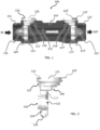
- an inline transducer meter assembly 100 is illustrated in accordance with an embodiment.
- the inline transducer meter assembly 100 can also be referred to generally in industry and within this description as a "flow tube assembly".
- the inline transducer meter assembly 100 includes an inline transducer meter body 110 with an inlet 111 where fluid can flow into the inline transducer meter assembly 100 and an outlet 112 where fluid can flow out of the inline transducer meter assembly 100.
- the inline transducer meter assembly 100 can be adapted to hold at least one transducer 121 between the inlet 111 and the outlet 112 and in-line with fluid flowing through an inline transducer meter body 110.
- FIG. 1 illustrates two transducers 121/121' mounted into the inline transducer meter body 110 between the inlet 111 and the outlet 112.
- the two transducers 121/121' shown in FIG. 1 can be, for example, two ultrasonic transducers facing each other within the inline transducer meter body 110.
- the configuration illustrated I FIG. 1 is not meant to limit the scope of the embodiments.
- the first transducer assembly 121 located near the inlet 111 can include a circular head section 123 having a circular ledge 127 adapted to interface in a complimentary manner with circular shelf 116 integrated in a flow tube.
- a square or rectangular alignment section 126 can be provided on the first transducer assembly 121 that extends from the circular head section 123 past the circular shelf 116 and can be formed and adapted to interface in a complimentary manner with a square or rectangular portal 117 formed between the circular shelf 116 and an inner surface 115 forming an interior of the inline transducer meter body 110.
- the square or rectangular alignment section 126 can have a reduced surface area to reduce upshot force on the square or rectangular alignment section 126 by fluid flowing through the inline transducer meter body 110 and past the square or rectangular portal 117.
- a transducer holding area 122 can be provided that extends from the square or rectangular alignment section 126 into a center inner area of the inline transducer meter body 110 wherein fluid flows through the inline transducer meter body 110.
- the transducer holder 122 can be adapted to retain a first transducer therein while in alignment within the inline transducer meter body 110 with a second transducer located in a transducer holder of a second transducer assembly 121' held within the inline transducer meter body 110 downline from the first transducer assembly 121 near the outlet 112.
- the first transducer holder 122 can be formed in a fluid flow enhancing profile and configured to retain a flow conditioner 131 in front of the fluid flowing through the inline transducer meter body 110.
- a fluid flow enhancing profile can also be accomplished by utilizing a first narrow support 128 formed between the first transducer holder 122 and the square or rectangular alignment section 126, and a second narrow support 129 formed between the first transducer holder 122 and a positioner formed on and extending from the narrow support 129 opposite the first transducer holder, wherein the positioner 124 can interface with a notch 113 that can be formed in the inner surface 115 of the inline transducer meter body 110 opposite the square or rectangular portal 117.
- the notch 113 can function as a location feature for the positioner 124.
- the positioner 124 can be further configured with its placement in the notch 113 to secure the first transducer assembly 121 and any transducer held within the first transducer holder 122 in alignment with fluid flowing through the inline transducer meter body 110.
- a second transducer assembly 121' located downline from the first transducer assembly 121 near the outlet 112 can also include a circular head section 123' having a circular ledge 127, a transducer holding area 122 that extends from a square or rectangular alignment section 126, a fluid flow enhancing profile with a transducer holding area 122 that can be configured to retain a flow conditioner 131', but behind fluid flowing through the inline transducer meter body 110.
- the fluid flow enhancing profile for the second transducer assembly 121' can also be accomplished by utilizing a first narrow support 128 formed between the transducer holder 122 and the square or rectangular alignment section 126 formed and adapted to interface with a square or rectangular portal 117' formed between circular shelf 116' and an inner surface 115, and a second narrow support 129 formed between the first transducer holder 122 and a positioner 124' formed on and extending from the narrow support 129 opposite the transducer holder 122, wherein positioner 124' can interface with a second notch 113' formed in the inner surface 115 of the inline transducer meter body 110 opposite a second square or rectangular portal 117'.
- positioner 124' can be configured given its secured interface with the notch 113' to further secure the second transducer assembly 121' and any transducer held within the first transducer holder 122 in alignment with fluid flowing through the inline transducer housing assembly body 110 near the outlet 112.
- the circular ledge 127 of the second transducer assembly 121' will be adapted to interface in a complimentary manner with circular shelf 116' integrated in the inline transducer meter body 110.
- a square or rectangular alignment section 126 can be provided on the second transducer assembly 121' that extends from the circular head section 123 past circular shelf 116' and can be formed and adapted to interface a complimentary manner with square or rectangular portal 117' formed between the circular shelf 116' and the inner surface 115 forming an interior of the inline transducer meter body 110.
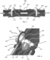
- an inline transducer housing assembly 200 is illustrated in accordance with another embodiment.
- the inline transducer housing assembly 200 shown here can also be referred to generally in industry as a "flow tube".
- the inline transducer meter assembly 200 can also include an inline transducer meter body 210 with an inlet 211 where fluid can flow into the inline transducer meter assembly 200 and an outlet 212 where fluid can flow out of the inline transducer meter assembly 200.
- the inline transducer meter assembly 200 can also be adapted to hold at least one transducer 121/121' between the inlet 211 and the outlet 212 and in-line with fluid flowing through an inline transducer meter body 210.
- the inline transducer meter assembly 200 can also have at least one circular shelf 116, at least one square or rectangular portal 117, and at least one notch 113 formed in the inline transducer meter body 210 of the inline transducer meter assembly 200.
- locking interfaces 217 and 218 can be formed with the inline transducer meter body 210 to connect the inline transducer meter assembly 200 with conduit 219/220 so that fluid if flowing through and into the inline transducer housing assembly 200 can be effectively spliced into the conduit for metering purposes.
- FIG. 4 illustrated is a close up perspective of a transducer 121 mounted in an inline transducer meter body 210.
- a rubber seal 150 in the form of an O-ring is shown mounted onto the circular ledge 127 of the circular head section 123.
- the rubber seal 150 can be used to create a tight seal between the circular ledge 127 where it can interface in a complimentary manner with circular shelf 216 formed on the inline transducer meter body 210.
- the conditioner 131 is also shown with fluid-flow enhancing arms 132/133 that can cover the first and second narrow supports 128/129 of the transducer holder 122.
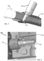
- a fabrication tool 300 that can be utilized to fabricate the inline transducer meter body 110 for the inline transducer meter assembly 100, hereinbefore described, that is formed using 3D printing techniques.
- the fabrication tool 300 can be utilized to 3D fabricate the inline transducer meter body 110.
- Additive manufacturing eliminates various design limitations imposed by existing production methods. Highly complex components that could not be produced in the past are now possible using additive manufacturing.
- the inline transducer meter body 110 can be formed on the surface of the fabrication tool 300, which can be made of metal.
- cooling channels 431/432 to introduce a fluid coolant into the tool to keep its surface cool as material is formed on the outer surface of the tool using additive manufacturing techniques, which are known to produce heat.
- Fluid can be introduced into channel 431 where it moves through coiled tubing 430/330, and then the fluid can be returned (i.e., exit from) channel 432. Fluid can flow continuously through the coiled tubing 430/330 during fabrication of the inline transducer assembly body 110.
- Cooled cores represented by fabrication tool 300 allow for the use of complex cooling channels, which help achieve dimensional stability and straightness for parts, such as the inline transducer meter body 110, during manufacturing.
- the fabrication tool 300 can be provided in two sections 310/410, which can be connected together 370 during processing of the inline transducer meter body 110.
- section 310 can be separated from section 410. What remains after section 310 and 410 are separated is the central core of a fabricated inline transducer meter body 110 as illustrated in FIGS 1 and 3 .
- the fabrication tool can include a channel 320/420 wherein a core 325 can be slid into the channel 320/420.
- the core 325 an prevent material from being placed/deposited where the core 325 is situated within the fabrication tool 300 during moulding/processing.
- FIG. 8 illustrated is an exemplary block diagram of components of an injection mould tool 500 including a core 325 and moving section 310 securely mounted for part moulding.
- Section 310 can be held within block 520 by brass threaded ends 219/220, while core 325 is inserted into section 310. Material can then flow over Section 310 to form the inline transducer meter body.
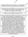
- a fabrication tool can be provided that can be mounted to a 3D moulding machine and liquid-cooled during fabrication.
- the fabrication tool can have moving sections created by a 3D printer and can include at least one cooling channel therein for accepting fluid coolant to keep the surface cool during fabrication of the inline transducer meter body.
- the fabrication tool can have at least one channel formed through the surface that is configured to receive a square or rectangular core therein to prevent material from being placed in the channel during fabrication.
- material can be added onto the surface of the fabrication tool while cooling the surface via coolant circulating through the at least one cooling channel.
- the core can be removed from the fabrication tool.
- the fabrication tool can be removed from the material that was added onto the surface of the fabrication tool resulting in an inline transducer meter body having an inner surface formed by the surface of the fabrication tool, an inlet and an outlet, a circular shelf integrated in an inline transducer meter body adapted to receive a transducer assembly that interfaces in a complimentary manner with a circular ledge of a circular head section of the transducer assembly, a square or rectangular portal formed between the circular shelf and an inner surface of the inline transducer meter body adapted to interface in a complimentary manner with an alignment section of the transducer assembly having a reduced surface area to reduce upshot force on the alignment section by fluid flowing through the inline transducer meter body and past the square or rectangular portal, and a notch formed in the inner surface of the
- the transducer holder can be positioned near a center of the inline transducer meter body between the square or rectangular portal and the notch.
- the positioner can be further configured to operate with the square or rectangular portal to secure the transducer holder in alignment with the fluid as it flows through the inline transducer meter body.
- Coolant fluid can be introduced into a first channel where it moves through coiled tubing within the fabrication tool and then the coolant fluid is returned from the fabrication tool from a second channel. Coolant fluid can flow continuously through the coiled tubing during fabrication of the inline transducer assembly body.
- the fabrication tool can also include a tapered surface. Two fabrication tools can be connected together to create a tapered inlet and a tapered outlet within the inline transducer assembly body. The two fabrication tools can then be separated after fabrication leaving an inline transducer assembly body that includes a tapered inlet and tapered outlet.
Landscapes
- Physics & Mathematics (AREA)
- Fluid Mechanics (AREA)
- General Physics & Mathematics (AREA)
- Electromagnetism (AREA)
- Measuring Volume Flow (AREA)
- Measurement Of Velocity Or Position Using Acoustic Or Ultrasonic Waves (AREA)
- Measuring Fluid Pressure (AREA)
Description
- Embodiments are related to fluid flow meters. More particularly, embodiments are related to a flow meter adapted to securely place and hold an inline transducer housing assembly within fluid flowing through a conduit. Embodiments are also related to use of an injection mould tool utilizing 3D printed inserts to render an inline transducer housing assembly body.
- Flow meters are sophisticated measuring devices that employ a range of technologies designed to quantify the rate or volume of a moving fluid, either liquid or gas, in an open or closed conduit. The type of flow meter used will vary by application, but coriolis, differential pressure, magmeter, electromagnetic, oval gear, thermal, paddlewheel, positive displacement and ultrasonic are the most commonly used technologies.
- Ultrasonic flow meters use sound waves as a reliable, accurate and maintenance free method to measure the velocity of a fluid from which the volumetric flow rate can be calculated. They feature no moving parts making them more reliable and accurate while providing maintenance-free operation. Since ultrasonic signals can also penetrate solid materials, the transducers can be mounted onto the outside of the pipe offering completely non-invasive measurement eliminating chemical compatibility issues, pressure restrictions, and pressure loss. Inline mounting of transducers, however, can provide the most accurate measurement of fluid flow.
- Despite improvements in technology, it can still be a challenge to achieve accurate fluid flow measurement over a long period of time without degradation of quality or sensor integrity given challenges that can be experienced when transducers are placed within (i.e., in-line with) the flow of fluid to be measured. What is needed are improvements in the placement of transducers within a conduit wherein fluid is flowing through the conduit.
- An example of a currently used system can be found in
FR3035513A1 - Embodiments are presented to achieve accurate inline fluid flow measurement over a long period while minimizing degradation of measurement data quality.
- The following summary is provided to facilitate an understanding of some of the features of the disclosed embodiments and is not intended to be a full description. A full appreciation of the various aspects of the embodiments disclosed herein can be gained by taking the specification, claims, drawings, and abstract as a whole.
- Embodiments presented are also to achieve accurate inline fluid flow measurement over a long period while minimizing degradation of quality by using ultrasonic flow-rate sensing technology.
- In accordance with the embodiments, a flow tube to support an inline transducer housing assembly can be fabricated by using a liquid cooled tool that can include a channel that can accept a core that can enable formation of a port to then accept a sensor assembly, and can also enable formation of a notch to help stabilize the sensor assembly in alignment with fluid flow.
- In accordance with another feature of the embodiment, a resulting assembly from fabrication can include a circular shelf formed on the housing assembly adapted to receive a transducer assembly that interfaces in a complimentary manner with a circular ledge of a circular head section of the transducer assembly, a portal formed between the circular shelf and an inner surface of the housing adapted to interface in a complimentary manner with an alignment section of the transducer, and a notch formed in the inner surface of the flow tube opposite the portal to interface with a positioner formed on and extending from a transducer holder operating to secure the transducer holder flow alignment.
- In accordance with yet another embodiment, an inline transducer meter assembly having an inlet and an outlet for fluid flowing through the inline transducer meter assembly from the inlet to the outlet is presented that includes a circular shelf integrated in an inline transducer meter body adapted to receive a transducer assembly that interfaces in a complimentary manner with a circular ledge of a circular head section of the transducer assembly, a square or rectangular portal formed between the circular shelf and an inner surface of the inline transducer meter body adapted to interface in a complimentary manner with an alignment section of the transducer assembly having a reduced surface area to reduce upshot force on the alignment section by fluid flowing through the inline transducer housing assembly body and past the square or rectangular portal, and a notch formed in the inner surface of the flow tube opposite the square or rectangular portal and adapted to interface with a positioner formed on and extending from a transducer holder as part of the transducer assembly, said transducer holder positioned near a center of the inline transducer meter body between the square or rectangular portal and the notch, said positioner further configured to operate with the square or rectangular portal to secure the transducer holder in alignment with the fluid as it flows through the inline transducer meter body.
- In accordance with another embodiment, a method for fabricating an inline transducer meter body with 3D moulding is described that includes steps of providing a fabrication tool that can be mounted to a 3D moulding machine, said fabrication tool having a moving section formed by a 3D printer and including at least one cooling channel therein for accepting fluid coolant to keep the surface cool during fabrication of the inline transducer meter body, wherein the fabrication tool has at least one channel formed through the surface that is configured to receive a square or rectangular core therein to prevent material from being placed in the channel during fabrication, adding material onto the surface using moulding while cooling the surface via coolant circulating through the at least one tool channel, removing the core from the fabrication tool, and removing the fabrication tool from the material added onto the surface of the fabrication tool. Removal of the core from the fabrication tool and then removal of the fabrication tool from material can result in an inline transducer meter body having an inner surface formed by the surface of the fabrication tool, an inlet and an outlet, a circular shelf integrated in an inline transducer meter body adapted to receive a transducer assembly that interfaces in a complimentary manner with a circular ledge of a circular head section of the transducer assembly a square or rectangular portal formed between the circular shelf and an inner surface of the inline transducer meter body adapted to interface in a complimentary manner with an alignment section of the transducer assembly having a reduced surface area to reduce upshot force on the alignment section by fluid flowing through the inline transducer meter body and past the square or rectangular portal, and a notch formed in the inner surface of the flow tube opposite the square or rectangular portal and adapted to interface with a positioner formed on and extending from a transducer holder as part of the transducer assembly, said transducer holder positioned near a center of the inline transducer meter body between the square or rectangular portal and the notch, said positioner further configured to operate with the square or rectangular portal to secure the transducer holder in alignment with the fluid as it flows through the inline transducer meter body.
- The accompanying figures, in which like reference numerals refer to identical or functionally-similar elements throughout the separate views and which are incorporated in and form a part of the specification, further illustrate the present invention and, together with the detailed description of the invention, serve to explain the principles of the present invention.
-
FIG. 1 illustrates a diagram of an inline transducer meter assembly, in accordance with the embodiments. -
FIG. 2 illustrates a diagram of transducer assembly, in accordance with the embodiments. -
FIG. 3 illustrates a diagram of another inline transducer meter assembly, in accordance with the embodiments. -
FIG. 4 illustrates a close up perspective of an inline transducer meter assembly with a transducer assembly installed therein, in accordance with the embodiments. -
FIG. 5 illustrates a diagram of a fabrication tool that can be utilized to fabricate an inline transducer housing assembly body for an inline transducer housing assembly, in accordance with the embodiments. -
FIG. 6 illustrates a diagram of an inline transducer housing assembly body formed around a fabrication tool and including a channel formed by a core when removed from the fabrication tool after fabrication, in accordance with the embodiments. -
FIG. 7 illustrates another diagram and perspective of an inline transducer housing assembly body formed around a fabrication tool and including a channel formed by a core while the core is installed in the fabrication tool during fabrication, in accordance with the embodiments. -
FIG. 8 illustrates an exemplary block diagram of components of an injection mould tool including a core and moving sections securely mounted to the system for moulding an inline transducer housing assembly body, in accordance with the embodiments. -
FIG. 9 illustrated a block diagram of a method for fabricating an inline transducer housing assembly body, in accordance with the embodiments. - The particular values and configurations discussed in these nonlimiting examples can be varied and are cited merely to illustrate one or more embodiments and are not intended to limit the scope thereof.
- Subject matter will now be described more fully hereinafter with reference to the accompanying drawings, which form a part hereof, and which show, by way of illustration, specific example embodiments. Subject matter may, however, be embodied in a variety of different forms and, therefore, covered or claimed subject matter is intended to be construed as not being limited to any example embodiments set forth herein; example embodiments are provided merely to be illustrative. Likewise, a reasonably broad scope for claimed or covered subject matter is intended. Among other issues, subject matter may be embodied as methods, devices, components, or systems. Accordingly, embodiments may, for example, take the form of hardware, software, firmware, or a combination thereof. The following detailed description is, therefore, not intended to be interpreted in a limiting sense.
- It is intended, for example, that claimed subject matter include combinations of example embodiments in whole or in part.
- In general, terminology may be understood, at least in part, from usage in context. For example, terms such as "and," "or," or "and/or" as used herein may include a variety of meanings that may depend, at least in part, upon the context in which such terms are used. Generally, "or" if used to associate a list, such as A, B, or C, is intended to mean A, B, and C, here used in the inclusive sense, as well as A, B, or C, here used in the exclusive sense. In addition, the term "one or more" as used herein, depending at least in part upon context, may be used to describe any feature, structure, or characteristic in a singular sense or may be used to describe combinations of features, structures, or characteristics in a plural sense. Similarly, terms such as "a," "an," or "the", again, may be understood to convey a singular usage or to convey a plural usage, depending at least in part upon context. In addition, the term "based on" may be understood as not necessarily intended to convey an exclusive set of factors and may, instead, allow for existence of additional factors not necessarily expressly described, again, depending at least in part on context.
- As discussed earlier flow meters used in industrial process can measure fluid moving through conduit. More effective measurements can be obtained when transducers are placed inline with the flowing fluid. The disclosed embodiments can offer a solution for providing a housing that can accommodate placing transducers inline with fluid flow. Although reference may be made to meter assemblies, embodiments are not limited to meters used to monitor fluid flow and can more broadly apply to "housings" that can accommodate various transducers for measurement purposes. The embodiments can be used in bi-directional operation conditions.
- Referring to
FIG. 1 , an inlinetransducer meter assembly 100 is illustrated in accordance with an embodiment. The inlinetransducer meter assembly 100 can also be referred to generally in industry and within this description as a "flow tube assembly". The inlinetransducer meter assembly 100 includes an inlinetransducer meter body 110 with aninlet 111 where fluid can flow into the inlinetransducer meter assembly 100 and anoutlet 112 where fluid can flow out of the inlinetransducer meter assembly 100. The inlinetransducer meter assembly 100 can be adapted to hold at least onetransducer 121 between theinlet 111 and theoutlet 112 and in-line with fluid flowing through an inlinetransducer meter body 110. - The embodiment shown in
FIG. 1 illustrates twotransducers 121/121' mounted into the inlinetransducer meter body 110 between theinlet 111 and theoutlet 112. Although it should be appreciated that a single transducer can be mounted into the inlinetransducer meter body 110 for some applications, the twotransducers 121/121' shown inFIG. 1 can be, for example, two ultrasonic transducers facing each other within the inlinetransducer meter body 110. The configuration illustrated IFIG. 1 is not meant to limit the scope of the embodiments. - Now referring to both
FIG. 1 and FIG. 2 , thefirst transducer assembly 121 located near theinlet 111 can include acircular head section 123 having acircular ledge 127 adapted to interface in a complimentary manner withcircular shelf 116 integrated in a flow tube. A square orrectangular alignment section 126 can be provided on thefirst transducer assembly 121 that extends from thecircular head section 123 past thecircular shelf 116 and can be formed and adapted to interface in a complimentary manner with a square orrectangular portal 117 formed between thecircular shelf 116 and aninner surface 115 forming an interior of the inlinetransducer meter body 110. The square orrectangular alignment section 126 can have a reduced surface area to reduce upshot force on the square orrectangular alignment section 126 by fluid flowing through the inlinetransducer meter body 110 and past the square orrectangular portal 117. Atransducer holding area 122 can be provided that extends from the square orrectangular alignment section 126 into a center inner area of the inlinetransducer meter body 110 wherein fluid flows through the inlinetransducer meter body 110. - Where two transducers are utilized, the
transducer holder 122 can be adapted to retain a first transducer therein while in alignment within the inlinetransducer meter body 110 with a second transducer located in a transducer holder of a second transducer assembly 121' held within the inlinetransducer meter body 110 downline from thefirst transducer assembly 121 near theoutlet 112. - The
first transducer holder 122 can be formed in a fluid flow enhancing profile and configured to retain aflow conditioner 131 in front of the fluid flowing through the inlinetransducer meter body 110. A fluid flow enhancing profile can also be accomplished by utilizing a firstnarrow support 128 formed between thefirst transducer holder 122 and the square orrectangular alignment section 126, and a secondnarrow support 129 formed between thefirst transducer holder 122 and a positioner formed on and extending from thenarrow support 129 opposite the first transducer holder, wherein thepositioner 124 can interface with anotch 113 that can be formed in theinner surface 115 of the inlinetransducer meter body 110 opposite the square orrectangular portal 117. Thenotch 113 can function as a location feature for thepositioner 124. Thepositioner 124 can be further configured with its placement in thenotch 113 to secure thefirst transducer assembly 121 and any transducer held within thefirst transducer holder 122 in alignment with fluid flowing through the inlinetransducer meter body 110. - Referring to
FIG. 1 again, where twocomplimentary transducers 121/121' are mounted in an inlinetransducer meter body 110, as can be the case where ultrasonic transducer are utilized, a second transducer assembly 121' located downline from thefirst transducer assembly 121 near theoutlet 112 can also include a circular head section 123' having acircular ledge 127, atransducer holding area 122 that extends from a square orrectangular alignment section 126, a fluid flow enhancing profile with atransducer holding area 122 that can be configured to retain a flow conditioner 131', but behind fluid flowing through the inlinetransducer meter body 110. The fluid flow enhancing profile for the second transducer assembly 121' can also be accomplished by utilizing a firstnarrow support 128 formed between thetransducer holder 122 and the square orrectangular alignment section 126 formed and adapted to interface with a square or rectangular portal 117' formed between circular shelf 116' and aninner surface 115, and a secondnarrow support 129 formed between thefirst transducer holder 122 and a positioner 124' formed on and extending from thenarrow support 129 opposite thetransducer holder 122, wherein positioner 124' can interface with a second notch 113' formed in theinner surface 115 of the inlinetransducer meter body 110 opposite a second square or rectangular portal 117'. As withpositioner 124, positioner 124' can be configured given its secured interface with the notch 113' to further secure the second transducer assembly 121' and any transducer held within thefirst transducer holder 122 in alignment with fluid flowing through the inline transducerhousing assembly body 110 near theoutlet 112. - The
circular ledge 127 of the second transducer assembly 121' will be adapted to interface in a complimentary manner with circular shelf 116' integrated in the inlinetransducer meter body 110. A square orrectangular alignment section 126 can be provided on the second transducer assembly 121' that extends from thecircular head section 123 past circular shelf 116' and can be formed and adapted to interface a complimentary manner with square or rectangular portal 117' formed between the circular shelf 116' and theinner surface 115 forming an interior of the inlinetransducer meter body 110. - Referring to
FIG. 3 , an inlinetransducer housing assembly 200 is illustrated in accordance with another embodiment. The inlinetransducer housing assembly 200 shown here can also be referred to generally in industry as a "flow tube". The inlinetransducer meter assembly 200 can also include an inlinetransducer meter body 210 with an inlet 211 where fluid can flow into the inlinetransducer meter assembly 200 and an outlet 212 where fluid can flow out of the inlinetransducer meter assembly 200. The inlinetransducer meter assembly 200 can also be adapted to hold at least onetransducer 121/121' between the inlet 211 and the outlet 212 and in-line with fluid flowing through an inlinetransducer meter body 210. The inlinetransducer meter assembly 200 can also have at least onecircular shelf 116, at least one square orrectangular portal 117, and at least onenotch 113 formed in the inlinetransducer meter body 210 of the inlinetransducer meter assembly 200. What is further shown inFIG. 3 is that lockinginterfaces transducer meter body 210 to connect the inlinetransducer meter assembly 200 withconduit 219/220 so that fluid if flowing through and into the inlinetransducer housing assembly 200 can be effectively spliced into the conduit for metering purposes. - Referring to
FIG. 4 , illustrated is a close up perspective of atransducer 121 mounted in an inlinetransducer meter body 210. Arubber seal 150 in the form of an O-ring is shown mounted onto thecircular ledge 127 of thecircular head section 123. Therubber seal 150 can be used to create a tight seal between thecircular ledge 127 where it can interface in a complimentary manner withcircular shelf 216 formed on the inlinetransducer meter body 210. Also shown in a conical shape of theconditioner 131. Theconditioner 131 is also shown with fluid-flow enhancing arms 132/133 that can cover the first and secondnarrow supports 128/129 of thetransducer holder 122. - Referring to
FIG. 5 , illustrated is afabrication tool 300 that can be utilized to fabricate the inlinetransducer meter body 110 for the inlinetransducer meter assembly 100, hereinbefore described, that is formed using 3D printing techniques. Thefabrication tool 300 can be utilized to 3D fabricate the inlinetransducer meter body 110. Additive manufacturing eliminates various design limitations imposed by existing production methods. Highly complex components that could not be produced in the past are now possible using additive manufacturing. The inlinetransducer meter body 110 can be formed on the surface of thefabrication tool 300, which can be made of metal. - As shown in
section 410 of thefabrication tool 300, incorporated therein can be coolingchannels 431/432 to introduce a fluid coolant into the tool to keep its surface cool as material is formed on the outer surface of the tool using additive manufacturing techniques, which are known to produce heat. Fluid can be introduced intochannel 431 where it moves through coiledtubing 430/330, and then the fluid can be returned (i.e., exit from)channel 432. Fluid can flow continuously through the coiledtubing 430/330 during fabrication of the inlinetransducer assembly body 110. Cooled cores represented byfabrication tool 300 allow for the use of complex cooling channels, which help achieve dimensional stability and straightness for parts, such as the inlinetransducer meter body 110, during manufacturing. - To achieve tapered shape of the
inner surface 115 of the inline transducerhousing assembly body 110, thefabrication tool 300 can be provided in twosections 310/410, which can be connected together 370 during processing of the inlinetransducer meter body 110. When fabrication of the inlinetransducer meter body 110 is completed,section 310 can be separated fromsection 410. What remains aftersection transducer meter body 110 as illustrated inFIGS 1 and3 . - Now referring to
FIGS. 5, 6 and7 , in order to accomplish formation of the square orrectangular portal 117 and thenotch 113 in the inlinetransducer meter body 110 during the moulding process, the fabrication tool can include achannel 320/420 wherein acore 325 can be slid into thechannel 320/420. The core 325 an prevent material from being placed/deposited where thecore 325 is situated within thefabrication tool 300 during moulding/processing. Once thecore 325 is removed (after moulding of the flow tube is completed), thenotch 113 will remain formed in the inner surface and square orrectangular portal 117 will remain formed through the inlinetransducer meter body 110. - Referring to
FIG. 8 , illustrated is an exemplary block diagram of components of aninjection mould tool 500 including acore 325 and movingsection 310 securely mounted for part moulding.Section 310 can be held withinblock 520 by brass threaded ends 219/220, whilecore 325 is inserted intosection 310. Material can then flow overSection 310 to form the inline transducer meter body. - Referring to
FIG. 9 , illustrated is a block diagram 600 of method steps for fabricating an inline transducer assembly body via 3D printing, in accordance with the embodiments. Referring toBlock 610, a fabrication tool can be provided that can be mounted to a 3D moulding machine and liquid-cooled during fabrication. The fabrication tool can have moving sections created by a 3D printer and can include at least one cooling channel therein for accepting fluid coolant to keep the surface cool during fabrication of the inline transducer meter body. The fabrication tool can have at least one channel formed through the surface that is configured to receive a square or rectangular core therein to prevent material from being placed in the channel during fabrication. Referring toBlock 620, material can be added onto the surface of the fabrication tool while cooling the surface via coolant circulating through the at least one cooling channel. Referring toBlock 630, the core can be removed from the fabrication tool. Then as shown inBlock 640 the fabrication tool can be removed from the material that was added onto the surface of the fabrication tool resulting in an inline transducer meter body having an inner surface formed by the surface of the fabrication tool, an inlet and an outlet, a circular shelf integrated in an inline transducer meter body adapted to receive a transducer assembly that interfaces in a complimentary manner with a circular ledge of a circular head section of the transducer assembly, a square or rectangular portal formed between the circular shelf and an inner surface of the inline transducer meter body adapted to interface in a complimentary manner with an alignment section of the transducer assembly having a reduced surface area to reduce upshot force on the alignment section by fluid flowing through the inline transducer meter body and past the square or rectangular portal, and a notch formed in the inner surface of the flow tube opposite the square or rectangular portal and adapted to interface with a positioner formed on and extending from a transducer holder as part of the transducer assembly. - The transducer holder can be positioned near a center of the inline transducer meter body between the square or rectangular portal and the notch. The positioner can be further configured to operate with the square or rectangular portal to secure the transducer holder in alignment with the fluid as it flows through the inline transducer meter body. Coolant fluid can be introduced into a first channel where it moves through coiled tubing within the fabrication tool and then the coolant fluid is returned from the fabrication tool from a second channel. Coolant fluid can flow continuously through the coiled tubing during fabrication of the inline transducer assembly body. The fabrication tool can also include a tapered surface. Two fabrication tools can be connected together to create a tapered inlet and a tapered outlet within the inline transducer assembly body. The two fabrication tools can then be separated after fabrication leaving an inline transducer assembly body that includes a tapered inlet and tapered outlet.
- It will be appreciated that variations of the above-disclosed embodiments and examples and other features and functions, or alternatives thereof, may be desirably combined into many other different systems or applications. It will also be appreciated that various presently unforeseen or unanticipated alternatives, modifications, variations or improvements therein may be subsequently made by those skilled in the art which are also intended to be encompassed by the following claims.
Claims (10)
- An inline transducer meter assembly (100) having an inlet (111) and an outlet (112) for fluid flowing through the inline transducer meter assembly from the inlet to the outlet, the inline transducer meter assembly comprising:a circular shelf (116') integrated in an inline transducer meter body (110) adapted to receive a transducer assembly (121, 121') that interfaces in a complimentary manner with a circular ledge (127) of a circular head section (123) of the transducer assembly;a square or rectangular portal (117) formed between the circular shelf and an inner surface (115) of the inline transducer meter body adapted to interface in a complimentary manner with an alignment section of the transducer assembly having a reduced surface area to reduce upshot force on the alignment section by fluid flowing through the inline transducer housing assembly body and past the square or rectangular portal; anda notch (113) formed in the inner surface of the flow tube opposite the square or rectangular portal and adapted to interface with a positioner (124) formed on and extending from a transducer holder (122) as part of the transducer assembly, said transducer holder positioned near a center of the inline transducer meter body between the square or rectangular portal and the notch, said positioner further configured to operate with the square or rectangular portal to secure the transducer holder in alignment with the fluid as it flows through the inline transducer meter body.
- The inline transducer meter assembly of claim 1, wherein the transducer holders of the transducer assembly and the second transducer assembly include piezoelectric element therein and in communication with each other.
- The inline transducer meter assembly of claim 2, wherein the piezoelectric element is connected by a wire that is accessible from the circular head section.
- The inline transducer meter assembly of claim 1, further comprising at least one flow conditioner (131, 131') coupled to a surface of at least one of the transducer holders to enhance flow of fluid passing through the inline transducer assembly body.
- The inline transducer meter assembly of claim 1, further comprising:a second circular shelf (116') integrated in the inline transducer meter body between the circular shelf and the outlet, said second circular shelf adapted to receive a second transducer assembly (121') and interface in a complimentary manner with the circular ledge of the circular head section of the second transducer assembly;a second square or rectangular portal (117') formed between the second circular shelf and the inner surface of the inline transducer meter body, said second square or rectangular portal adapted to interface in a complimentary manner with an alignment section of the second transducer assembly having a reduced surface area to reduce upshot force on the alignment section by fluid flowing through the inline transducer meter body and past the second square or rectangular portal; anda second notch (113') formed in the inner surface of the inline transducer meter body opposite the second square or rectangular portal and adapted to interface with a positioner (124") formed on and extending from a transducer holder (122') as part of the second transducer assembly (122'), said transducer holder positioned near a center of the inline transducer meter body between the second square or rectangular portal and the second notch, said positioner further configured to operate with the second square or rectangular portal to secure the transducer holder in alignment with fluid flowing through the inline transducer meter body.
- The inline transducer meter assembly of claim 5, wherein the transducer assembly is positioned with its transducer holder in the inline transducer meter body near the inlet and the second transducer assembly is positioned near the outlet with its transducer holder in the inline transducer meter body and in alignment with the transducer assembly's transducer holder.
- The inline transducer meter assembly of claim 5, wherein the transducer holders of the transducer assembly and the second transducer assembly include piezoelectric element therein and in communication with each other.
- The inline transducer meter assembly of claim 1, comprising:the circular head section having the circular ledge adapted to interface with circular shelf integrated in the flow tube;a square or rectangular alignment section extending from the circular head section within the circular shelf and adapted to interface with the square or rectangular portal formed between the shelf and an inner surface of the flow tube, said square or rectangular alignment section having a reduced surface area to reduce upshot force on the square or rectangular alignment section by fluid flowing through the flow tube; andthe transducer holder extending from the square or rectangular alignment section into an inner area of the flow tube wherein fluid flows through the flow tube, said transducer holder adapted to retain a first transducer in alignment with a second transducer located in the flow tube downline from the transducer, said transducer holder formed in a fluid flow enhancing profile and configured to retain a flow conditioner in front of the fluid flowing through the flow tube.
- The inline transducer meter assembly of claim 8, further comprising:a second circular shelf integrated in the inline transducer meter body between the circular shelf and the outlet, said second circular shelf adapted to receive a second transducer assembly and interface in a complimentary manner with a circular ledge of a circular head section of the second transducer assembly;a second square or rectangular portal formed between the second circular shelf and the inner surface of the inline transducer meter body, said second square or rectangular portal adapted to interface in a complimentary manner with an alignment section of the second transducer assembly having a reduced surface area to reduce upshot force on the alignment section by fluid flowing through the inline transducer meter body and past the second square or rectangular portal; anda second notch formed in the inner surface of the inline transducer meter body opposite the second square or rectangular portal and adapted to interface with a positioner formed on and extending from a transducer holder as part of the second transducer assembly, said transducer holder positioned near a center of the inline transducer meter body between the second square or rectangular portal and the second notch, said positioner further configured to operate with the second square or rectangular portal to secure the transducer holder in alignment with fluid flowing through the inline transducer meter body.
- A method for fabricating an inline transducer meter body with 3D moulding, comprising the steps of:provide a fabrication tool that can be mounted to a 3D moulding machine, said fabrication tool having a moving section formed by a 3D printer and including at least one cooling channel therein for accepting fluid coolant to keep the surface cool during fabrication of the inline transducer meter body, wherein the fabrication tool has at least one channel formed through the surface that is configured to receive a square or rectangular core therein to prevent material from being placed in the channel during fabrication;add material onto the surface using moulding while cooling the surface via coolant circulating through the at least one tool channel;remove the core from the fabrication tool; andremove the fabrication tool from the material added onto the surface of the fabrication tool;wherein removal of the core from the fabrication tool and then removal of the fabrication tool from material results in an inline transducer meter body having: an inner surface formed by the surface of the fabrication tool; an inlet and an outlet; a circular shelf integrated in an inline transducer meter body adapted to receive a transducer assembly that interfaces in a complimentary manner with a circular ledge of a circular head section of the transducer assembly; a square or rectangular portal formed between the circular shelf and an inner surface of the inline transducer meter body adapted to interface in a complimentary manner with an alignment section of the transducer assembly having a reduced surface area to reduce upshot force on the alignment section by fluid flowing through the inline transducer meter body and past the square or rectangular portal; and a notch formed in the inner surface of the flow tube opposite the square or rectangular portal and adapted to interface with a positioner formed on and extending from a transducer holder as part of the transducer assembly, said transducer holder positioned near a center of the inline transducer meter body between the square or rectangular portal and the notch, said positioner further configured to operate with the square or rectangular portal to secure the transducer holder in alignment with the fluid as it flows through the inline transducer meter body.
Applications Claiming Priority (1)
| Application Number | Priority Date | Filing Date | Title |
|---|---|---|---|
| US17/176,168 US11906337B2 (en) | 2021-02-15 | 2021-02-15 | Inline transducer housing assembly |
Publications (2)
| Publication Number | Publication Date |
|---|---|
| EP4043839A1 EP4043839A1 (en) | 2022-08-17 |
| EP4043839B1 true EP4043839B1 (en) | 2024-07-24 |
Family
ID=80034975
Family Applications (1)
| Application Number | Title | Priority Date | Filing Date |
|---|---|---|---|
| EP22153492.8A Active EP4043839B1 (en) | 2021-02-15 | 2022-01-26 | Inline transducer housing assembly |
Country Status (3)
| Country | Link |
|---|---|
| US (1) | US11906337B2 (en) |
| EP (1) | EP4043839B1 (en) |
| AU (1) | AU2022200336B2 (en) |
Family Cites Families (6)
| Publication number | Priority date | Publication date | Assignee | Title |
|---|---|---|---|---|
| JPH10142017A (en) * | 1996-11-11 | 1998-05-29 | Saginomiya Seisakusho Inc | Karman vortex flowmeter |
| CA2617287C (en) * | 1997-06-17 | 2011-11-15 | Fisher & Paykel Healthcare Limited | Respiratory humidification system |
| FR3032524B1 (en) * | 2015-02-10 | 2017-03-24 | Yzatec | ULTRASOUND TRANSDUCER, ITS MOUNTING METHOD AND FLOWMETER COMPRISING AT LEAST ONE SUCH TRANSDUCER |
| FR3035513B1 (en) * | 2015-04-23 | 2018-09-07 | Integra Metering Sas | DEVICE FOR MEASURING FLOW RATE OF ULTRASONIC TRANSDUCER (S) FLUID (S) |
| FR3047068B1 (en) * | 2016-01-25 | 2019-07-19 | Integra Metering Sas | DEVICE FOR MOUNTING AN ULTRASOUND TRANSDUCER AND FLOW METER EQUIPPED WITH SUCH A DEVICE |
| US10823597B2 (en) * | 2017-12-14 | 2020-11-03 | Arad Ltd. | Ultrasonic water meter including a metallic outer body and polymeric inner lining sleeve |
-
2021
- 2021-02-15 US US17/176,168 patent/US11906337B2/en active Active
-
2022
- 2022-01-19 AU AU2022200336A patent/AU2022200336B2/en active Active
- 2022-01-26 EP EP22153492.8A patent/EP4043839B1/en active Active
Also Published As
| Publication number | Publication date |
|---|---|
| AU2022200336B2 (en) | 2022-12-15 |
| US20220260401A1 (en) | 2022-08-18 |
| AU2022200336A1 (en) | 2022-09-01 |
| US11906337B2 (en) | 2024-02-20 |
| EP4043839A1 (en) | 2022-08-17 |
Similar Documents
| Publication | Publication Date | Title |
|---|---|---|
| US8181534B2 (en) | Ultrasonic flow meter with transducer assembly, and method of manufacturing the same while maintaining the radial position of the piezoelectric element | |
| EP2920556B1 (en) | System and method for ultrasonic metering using an orifice meter fitting | |
| US9372106B2 (en) | Non-circular flowmeter | |
| CN211205407U (en) | Ultrasonic flow meter and transducer assembly | |
| EP2893300B1 (en) | Differential pressure flow meter with angled pressure ports | |
| JP6408553B2 (en) | Magnetic flow meter with adhesive PTFE electrode | |
| US9297679B2 (en) | Flowmeter with a flow conditioner formed by a protrusion having restriction provided upstream of the measurement section | |
| CN103733031A (en) | Sensor module for measuring and/or monitoring parameters of media flowing in pipelines and measuring system formed therewith | |
| AU2022200336B2 (en) | Inline transducer housing assembly | |
| JP4455000B2 (en) | Gas meter | |
| EP3798582B1 (en) | Ultrasonic flowmeter and fluid pipeline | |
| US11846531B2 (en) | Ultrasonic flow meter with inner and outer flow channels | |
| CN112577557B (en) | Ultrasonic flowmeter and fluid pipeline | |
| JP5434308B2 (en) | Ultrasonic flow meter | |
| US20230012765A1 (en) | Method for producing a measurement tube assembly for a coriolis flow meter | |
| CN119836562A (en) | Combined enclosure for ultrasonic flow meter | |
| JP4789435B2 (en) | Ultrasonic flow meter | |
| JP4443980B2 (en) | Flow rate detector | |
| Monji et al. | Characteristics of Ultrasonic Flowmeter Located Downstream of Elbow | |
| KR20080005041U (en) | Flow Meter with Orifice |
Legal Events
| Date | Code | Title | Description |
|---|---|---|---|
| PUAI | Public reference made under article 153(3) epc to a published international application that has entered the european phase |
Free format text: ORIGINAL CODE: 0009012 |
|
| STAA | Information on the status of an ep patent application or granted ep patent |
Free format text: STATUS: REQUEST FOR EXAMINATION WAS MADE |
|
| 17P | Request for examination filed |
Effective date: 20220126 |
|
| AK | Designated contracting states |
Kind code of ref document: A1 Designated state(s): AL AT BE BG CH CY CZ DE DK EE ES FI FR GB GR HR HU IE IS IT LI LT LU LV MC MK MT NL NO PL PT RO RS SE SI SK SM TR |
|
| P01 | Opt-out of the competence of the unified patent court (upc) registered |
Effective date: 20230414 |
|
| GRAP | Despatch of communication of intention to grant a patent |
Free format text: ORIGINAL CODE: EPIDOSNIGR1 |
|
| STAA | Information on the status of an ep patent application or granted ep patent |
Free format text: STATUS: GRANT OF PATENT IS INTENDED |
|
| RIC1 | Information provided on ipc code assigned before grant |
Ipc: G01F 15/18 20060101ALI20240220BHEP Ipc: G01D 11/30 20060101ALI20240220BHEP Ipc: G01F 1/66 20220101AFI20240220BHEP |
|
| INTG | Intention to grant announced |
Effective date: 20240311 |
|
| GRAS | Grant fee paid |
Free format text: ORIGINAL CODE: EPIDOSNIGR3 |
|
| GRAA | (expected) grant |
Free format text: ORIGINAL CODE: 0009210 |
|
| STAA | Information on the status of an ep patent application or granted ep patent |
Free format text: STATUS: THE PATENT HAS BEEN GRANTED |
|
| AK | Designated contracting states |
Kind code of ref document: B1 Designated state(s): AL AT BE BG CH CY CZ DE DK EE ES FI FR GB GR HR HU IE IS IT LI LT LU LV MC MK MT NL NO PL PT RO RS SE SI SK SM TR |
|
| REG | Reference to a national code |
Ref country code: GB Ref legal event code: FG4D |
|
| REG | Reference to a national code |
Ref country code: CH Ref legal event code: EP |
|
| REG | Reference to a national code |
Ref country code: IE Ref legal event code: FG4D Ref country code: DE Ref legal event code: R096 Ref document number: 602022004679 Country of ref document: DE |
|
| REG | Reference to a national code |
Ref country code: LT Ref legal event code: MG9D |
|
| REG | Reference to a national code |
Ref country code: NL Ref legal event code: MP Effective date: 20240724 |
|
| PG25 | Lapsed in a contracting state [announced via postgrant information from national office to epo] |
Ref country code: PT Free format text: LAPSE BECAUSE OF FAILURE TO SUBMIT A TRANSLATION OF THE DESCRIPTION OR TO PAY THE FEE WITHIN THE PRESCRIBED TIME-LIMIT Effective date: 20241125 |
|
| REG | Reference to a national code |
Ref country code: AT Ref legal event code: MK05 Ref document number: 1706685 Country of ref document: AT Kind code of ref document: T Effective date: 20240724 |
|
| PG25 | Lapsed in a contracting state [announced via postgrant information from national office to epo] |
Ref country code: NL Free format text: LAPSE BECAUSE OF FAILURE TO SUBMIT A TRANSLATION OF THE DESCRIPTION OR TO PAY THE FEE WITHIN THE PRESCRIBED TIME-LIMIT Effective date: 20240724 |
|
| PG25 | Lapsed in a contracting state [announced via postgrant information from national office to epo] |
Ref country code: PT Free format text: LAPSE BECAUSE OF FAILURE TO SUBMIT A TRANSLATION OF THE DESCRIPTION OR TO PAY THE FEE WITHIN THE PRESCRIBED TIME-LIMIT Effective date: 20241125 Ref country code: NL Free format text: LAPSE BECAUSE OF FAILURE TO SUBMIT A TRANSLATION OF THE DESCRIPTION OR TO PAY THE FEE WITHIN THE PRESCRIBED TIME-LIMIT Effective date: 20240724 |
|
| PG25 | Lapsed in a contracting state [announced via postgrant information from national office to epo] |
Ref country code: NO Free format text: LAPSE BECAUSE OF FAILURE TO SUBMIT A TRANSLATION OF THE DESCRIPTION OR TO PAY THE FEE WITHIN THE PRESCRIBED TIME-LIMIT Effective date: 20241024 |
|
| PG25 | Lapsed in a contracting state [announced via postgrant information from national office to epo] |
Ref country code: PL Free format text: LAPSE BECAUSE OF FAILURE TO SUBMIT A TRANSLATION OF THE DESCRIPTION OR TO PAY THE FEE WITHIN THE PRESCRIBED TIME-LIMIT Effective date: 20240724 Ref country code: GR Free format text: LAPSE BECAUSE OF FAILURE TO SUBMIT A TRANSLATION OF THE DESCRIPTION OR TO PAY THE FEE WITHIN THE PRESCRIBED TIME-LIMIT Effective date: 20241025 Ref country code: FI Free format text: LAPSE BECAUSE OF FAILURE TO SUBMIT A TRANSLATION OF THE DESCRIPTION OR TO PAY THE FEE WITHIN THE PRESCRIBED TIME-LIMIT Effective date: 20240724 |
|
| PG25 | Lapsed in a contracting state [announced via postgrant information from national office to epo] |
Ref country code: BG Free format text: LAPSE BECAUSE OF FAILURE TO SUBMIT A TRANSLATION OF THE DESCRIPTION OR TO PAY THE FEE WITHIN THE PRESCRIBED TIME-LIMIT Effective date: 20240724 |
|
| PG25 | Lapsed in a contracting state [announced via postgrant information from national office to epo] |
Ref country code: LV Free format text: LAPSE BECAUSE OF FAILURE TO SUBMIT A TRANSLATION OF THE DESCRIPTION OR TO PAY THE FEE WITHIN THE PRESCRIBED TIME-LIMIT Effective date: 20240724 |
|
| PG25 | Lapsed in a contracting state [announced via postgrant information from national office to epo] |
Ref country code: AT Free format text: LAPSE BECAUSE OF FAILURE TO SUBMIT A TRANSLATION OF THE DESCRIPTION OR TO PAY THE FEE WITHIN THE PRESCRIBED TIME-LIMIT Effective date: 20240724 Ref country code: IS Free format text: LAPSE BECAUSE OF FAILURE TO SUBMIT A TRANSLATION OF THE DESCRIPTION OR TO PAY THE FEE WITHIN THE PRESCRIBED TIME-LIMIT Effective date: 20241124 |
|
| PG25 | Lapsed in a contracting state [announced via postgrant information from national office to epo] |
Ref country code: HR Free format text: LAPSE BECAUSE OF FAILURE TO SUBMIT A TRANSLATION OF THE DESCRIPTION OR TO PAY THE FEE WITHIN THE PRESCRIBED TIME-LIMIT Effective date: 20240724 |
|
| PG25 | Lapsed in a contracting state [announced via postgrant information from national office to epo] |
Ref country code: RS Free format text: LAPSE BECAUSE OF FAILURE TO SUBMIT A TRANSLATION OF THE DESCRIPTION OR TO PAY THE FEE WITHIN THE PRESCRIBED TIME-LIMIT Effective date: 20241024 Ref country code: ES Free format text: LAPSE BECAUSE OF FAILURE TO SUBMIT A TRANSLATION OF THE DESCRIPTION OR TO PAY THE FEE WITHIN THE PRESCRIBED TIME-LIMIT Effective date: 20240724 |
|
| PG25 | Lapsed in a contracting state [announced via postgrant information from national office to epo] |
Ref country code: RS Free format text: LAPSE BECAUSE OF FAILURE TO SUBMIT A TRANSLATION OF THE DESCRIPTION OR TO PAY THE FEE WITHIN THE PRESCRIBED TIME-LIMIT Effective date: 20241024 Ref country code: PL Free format text: LAPSE BECAUSE OF FAILURE TO SUBMIT A TRANSLATION OF THE DESCRIPTION OR TO PAY THE FEE WITHIN THE PRESCRIBED TIME-LIMIT Effective date: 20240724 Ref country code: NO Free format text: LAPSE BECAUSE OF FAILURE TO SUBMIT A TRANSLATION OF THE DESCRIPTION OR TO PAY THE FEE WITHIN THE PRESCRIBED TIME-LIMIT Effective date: 20241024 Ref country code: LV Free format text: LAPSE BECAUSE OF FAILURE TO SUBMIT A TRANSLATION OF THE DESCRIPTION OR TO PAY THE FEE WITHIN THE PRESCRIBED TIME-LIMIT Effective date: 20240724 Ref country code: IS Free format text: LAPSE BECAUSE OF FAILURE TO SUBMIT A TRANSLATION OF THE DESCRIPTION OR TO PAY THE FEE WITHIN THE PRESCRIBED TIME-LIMIT Effective date: 20241124 Ref country code: HR Free format text: LAPSE BECAUSE OF FAILURE TO SUBMIT A TRANSLATION OF THE DESCRIPTION OR TO PAY THE FEE WITHIN THE PRESCRIBED TIME-LIMIT Effective date: 20240724 Ref country code: GR Free format text: LAPSE BECAUSE OF FAILURE TO SUBMIT A TRANSLATION OF THE DESCRIPTION OR TO PAY THE FEE WITHIN THE PRESCRIBED TIME-LIMIT Effective date: 20241025 Ref country code: FI Free format text: LAPSE BECAUSE OF FAILURE TO SUBMIT A TRANSLATION OF THE DESCRIPTION OR TO PAY THE FEE WITHIN THE PRESCRIBED TIME-LIMIT Effective date: 20240724 Ref country code: ES Free format text: LAPSE BECAUSE OF FAILURE TO SUBMIT A TRANSLATION OF THE DESCRIPTION OR TO PAY THE FEE WITHIN THE PRESCRIBED TIME-LIMIT Effective date: 20240724 Ref country code: BG Free format text: LAPSE BECAUSE OF FAILURE TO SUBMIT A TRANSLATION OF THE DESCRIPTION OR TO PAY THE FEE WITHIN THE PRESCRIBED TIME-LIMIT Effective date: 20240724 Ref country code: AT Free format text: LAPSE BECAUSE OF FAILURE TO SUBMIT A TRANSLATION OF THE DESCRIPTION OR TO PAY THE FEE WITHIN THE PRESCRIBED TIME-LIMIT Effective date: 20240724 |
|
| PG25 | Lapsed in a contracting state [announced via postgrant information from national office to epo] |
Ref country code: RO Free format text: LAPSE BECAUSE OF FAILURE TO SUBMIT A TRANSLATION OF THE DESCRIPTION OR TO PAY THE FEE WITHIN THE PRESCRIBED TIME-LIMIT Effective date: 20240724 Ref country code: DK Free format text: LAPSE BECAUSE OF FAILURE TO SUBMIT A TRANSLATION OF THE DESCRIPTION OR TO PAY THE FEE WITHIN THE PRESCRIBED TIME-LIMIT Effective date: 20240724 Ref country code: SM Free format text: LAPSE BECAUSE OF FAILURE TO SUBMIT A TRANSLATION OF THE DESCRIPTION OR TO PAY THE FEE WITHIN THE PRESCRIBED TIME-LIMIT Effective date: 20240724 |
|
| PG25 | Lapsed in a contracting state [announced via postgrant information from national office to epo] |
Ref country code: EE Free format text: LAPSE BECAUSE OF FAILURE TO SUBMIT A TRANSLATION OF THE DESCRIPTION OR TO PAY THE FEE WITHIN THE PRESCRIBED TIME-LIMIT Effective date: 20240724 |
|
| PG25 | Lapsed in a contracting state [announced via postgrant information from national office to epo] |
Ref country code: CZ Free format text: LAPSE BECAUSE OF FAILURE TO SUBMIT A TRANSLATION OF THE DESCRIPTION OR TO PAY THE FEE WITHIN THE PRESCRIBED TIME-LIMIT Effective date: 20240724 |
|
| REG | Reference to a national code |
Ref country code: DE Ref legal event code: R097 Ref document number: 602022004679 Country of ref document: DE |
|
| PG25 | Lapsed in a contracting state [announced via postgrant information from national office to epo] |
Ref country code: SK Free format text: LAPSE BECAUSE OF FAILURE TO SUBMIT A TRANSLATION OF THE DESCRIPTION OR TO PAY THE FEE WITHIN THE PRESCRIBED TIME-LIMIT Effective date: 20240724 Ref country code: IT Free format text: LAPSE BECAUSE OF FAILURE TO SUBMIT A TRANSLATION OF THE DESCRIPTION OR TO PAY THE FEE WITHIN THE PRESCRIBED TIME-LIMIT Effective date: 20240724 |
|
| PLBE | No opposition filed within time limit |
Free format text: ORIGINAL CODE: 0009261 |
|
| STAA | Information on the status of an ep patent application or granted ep patent |
Free format text: STATUS: NO OPPOSITION FILED WITHIN TIME LIMIT |
|
| 26N | No opposition filed |
Effective date: 20250425 |
|
| REG | Reference to a national code |
Ref country code: DE Ref legal event code: R119 Ref document number: 602022004679 Country of ref document: DE |
|
| REG | Reference to a national code |
Ref country code: CH Ref legal event code: PL |
|
| PG25 | Lapsed in a contracting state [announced via postgrant information from national office to epo] |
Ref country code: SE Free format text: LAPSE BECAUSE OF FAILURE TO SUBMIT A TRANSLATION OF THE DESCRIPTION OR TO PAY THE FEE WITHIN THE PRESCRIBED TIME-LIMIT Effective date: 20240724 |
|
| PG25 | Lapsed in a contracting state [announced via postgrant information from national office to epo] |
Ref country code: LU Free format text: LAPSE BECAUSE OF NON-PAYMENT OF DUE FEES Effective date: 20250126 Ref country code: MC Free format text: LAPSE BECAUSE OF FAILURE TO SUBMIT A TRANSLATION OF THE DESCRIPTION OR TO PAY THE FEE WITHIN THE PRESCRIBED TIME-LIMIT Effective date: 20240724 |
|
| PG25 | Lapsed in a contracting state [announced via postgrant information from national office to epo] |
Ref country code: DE Free format text: LAPSE BECAUSE OF NON-PAYMENT OF DUE FEES Effective date: 20250801 |
|
| PG25 | Lapsed in a contracting state [announced via postgrant information from national office to epo] |
Ref country code: BE Free format text: LAPSE BECAUSE OF NON-PAYMENT OF DUE FEES Effective date: 20250131 |
|
| PG25 | Lapsed in a contracting state [announced via postgrant information from national office to epo] |
Ref country code: FR Free format text: LAPSE BECAUSE OF NON-PAYMENT OF DUE FEES Effective date: 20250131 |
|
| PG25 | Lapsed in a contracting state [announced via postgrant information from national office to epo] |
Ref country code: CH Free format text: LAPSE BECAUSE OF NON-PAYMENT OF DUE FEES Effective date: 20250131 |
|
| REG | Reference to a national code |
Ref country code: BE Ref legal event code: MM Effective date: 20250131 |
|
| PG25 | Lapsed in a contracting state [announced via postgrant information from national office to epo] |
Ref country code: IE Free format text: LAPSE BECAUSE OF NON-PAYMENT OF DUE FEES Effective date: 20250126 |