EP4043820A1 - Safety buffered multi-fluid heat exchanger and safety buffered multi-fluid heat exchange process - Google Patents
Safety buffered multi-fluid heat exchanger and safety buffered multi-fluid heat exchange process Download PDFInfo
- Publication number
- EP4043820A1 EP4043820A1 EP20870147.4A EP20870147A EP4043820A1 EP 4043820 A1 EP4043820 A1 EP 4043820A1 EP 20870147 A EP20870147 A EP 20870147A EP 4043820 A1 EP4043820 A1 EP 4043820A1
- Authority
- EP
- European Patent Office
- Prior art keywords
- fluid
- tubing
- hot
- cold
- heat exchanger
- Prior art date
- Legal status (The legal status is an assumption and is not a legal conclusion. Google has not performed a legal analysis and makes no representation as to the accuracy of the status listed.)
- Withdrawn
Links
- 239000012530 fluid Substances 0.000 title claims abstract description 248
- 238000000034 method Methods 0.000 title claims abstract description 90
- 238000010438 heat treatment Methods 0.000 claims description 8
- 238000010276 construction Methods 0.000 claims description 7
- 239000000126 substance Substances 0.000 claims description 6
- 239000012809 cooling fluid Substances 0.000 claims description 5
- 239000007788 liquid Substances 0.000 claims description 4
- 239000007791 liquid phase Substances 0.000 claims description 4
- 230000001174 ascending effect Effects 0.000 claims description 2
- 230000008016 vaporization Effects 0.000 claims description 2
- QAOWNCQODCNURD-UHFFFAOYSA-N Sulfuric acid Chemical compound OS(O)(=O)=O QAOWNCQODCNURD-UHFFFAOYSA-N 0.000 description 16
- 238000009835 boiling Methods 0.000 description 10
- XLYOFNOQVPJJNP-UHFFFAOYSA-N water Substances O XLYOFNOQVPJJNP-UHFFFAOYSA-N 0.000 description 8
- 238000001816 cooling Methods 0.000 description 5
- 238000000354 decomposition reaction Methods 0.000 description 4
- 230000007257 malfunction Effects 0.000 description 4
- 238000004519 manufacturing process Methods 0.000 description 4
- 239000000047 product Substances 0.000 description 4
- 230000008901 benefit Effects 0.000 description 3
- 230000015572 biosynthetic process Effects 0.000 description 3
- 238000006243 chemical reaction Methods 0.000 description 3
- NBIIXXVUZAFLBC-UHFFFAOYSA-N Phosphoric acid Chemical compound OP(O)(O)=O NBIIXXVUZAFLBC-UHFFFAOYSA-N 0.000 description 2
- 150000001412 amines Chemical class 0.000 description 2
- 239000006227 byproduct Substances 0.000 description 2
- 238000009833 condensation Methods 0.000 description 2
- 230000005494 condensation Effects 0.000 description 2
- 238000011109 contamination Methods 0.000 description 2
- 238000001704 evaporation Methods 0.000 description 2
- 230000008020 evaporation Effects 0.000 description 2
- 238000004880 explosion Methods 0.000 description 2
- 238000005755 formation reaction Methods 0.000 description 2
- 238000012423 maintenance Methods 0.000 description 2
- 239000000463 material Substances 0.000 description 2
- 229910000147 aluminium phosphate Inorganic materials 0.000 description 1
- 230000015556 catabolic process Effects 0.000 description 1
- 238000012512 characterization method Methods 0.000 description 1
- 238000001311 chemical methods and process Methods 0.000 description 1
- 230000007797 corrosion Effects 0.000 description 1
- 238000005260 corrosion Methods 0.000 description 1
- 238000006731 degradation reaction Methods 0.000 description 1
- 230000006866 deterioration Effects 0.000 description 1
- 230000000694 effects Effects 0.000 description 1
- 238000005516 engineering process Methods 0.000 description 1
- 150000002334 glycols Chemical class 0.000 description 1
- 229930195733 hydrocarbon Natural products 0.000 description 1
- 150000002430 hydrocarbons Chemical class 0.000 description 1
- 229910052739 hydrogen Inorganic materials 0.000 description 1
- 239000001257 hydrogen Substances 0.000 description 1
- 125000004435 hydrogen atom Chemical class [H]* 0.000 description 1
- 230000001771 impaired effect Effects 0.000 description 1
- 239000000203 mixture Substances 0.000 description 1
- 238000005979 thermal decomposition reaction Methods 0.000 description 1
Images






Classifications
-
- F—MECHANICAL ENGINEERING; LIGHTING; HEATING; WEAPONS; BLASTING
- F28—HEAT EXCHANGE IN GENERAL
- F28D—HEAT-EXCHANGE APPARATUS, NOT PROVIDED FOR IN ANOTHER SUBCLASS, IN WHICH THE HEAT-EXCHANGE MEDIA DO NOT COME INTO DIRECT CONTACT
- F28D15/00—Heat-exchange apparatus with the intermediate heat-transfer medium in closed tubes passing into or through the conduit walls ; Heat-exchange apparatus employing intermediate heat-transfer medium or bodies
-
- F—MECHANICAL ENGINEERING; LIGHTING; HEATING; WEAPONS; BLASTING
- F28—HEAT EXCHANGE IN GENERAL
- F28D—HEAT-EXCHANGE APPARATUS, NOT PROVIDED FOR IN ANOTHER SUBCLASS, IN WHICH THE HEAT-EXCHANGE MEDIA DO NOT COME INTO DIRECT CONTACT
- F28D7/00—Heat-exchange apparatus having stationary tubular conduit assemblies for both heat-exchange media, the media being in contact with different sides of a conduit wall
- F28D7/0066—Multi-circuit heat-exchangers, e.g. integrating different heat exchange sections in the same unit or heat-exchangers for more than two fluids
-
- F—MECHANICAL ENGINEERING; LIGHTING; HEATING; WEAPONS; BLASTING
- F28—HEAT EXCHANGE IN GENERAL
- F28D—HEAT-EXCHANGE APPARATUS, NOT PROVIDED FOR IN ANOTHER SUBCLASS, IN WHICH THE HEAT-EXCHANGE MEDIA DO NOT COME INTO DIRECT CONTACT
- F28D1/00—Heat-exchange apparatus having stationary conduit assemblies for one heat-exchange medium only, the media being in contact with different sides of the conduit wall, in which the other heat-exchange medium is a large body of fluid, e.g. domestic or motor car radiators
- F28D1/02—Heat-exchange apparatus having stationary conduit assemblies for one heat-exchange medium only, the media being in contact with different sides of the conduit wall, in which the other heat-exchange medium is a large body of fluid, e.g. domestic or motor car radiators with heat-exchange conduits immersed in the body of fluid
- F28D1/0226—Heat-exchange apparatus having stationary conduit assemblies for one heat-exchange medium only, the media being in contact with different sides of the conduit wall, in which the other heat-exchange medium is a large body of fluid, e.g. domestic or motor car radiators with heat-exchange conduits immersed in the body of fluid with an intermediate heat-transfer medium, e.g. thermosiphon radiators
-
- F—MECHANICAL ENGINEERING; LIGHTING; HEATING; WEAPONS; BLASTING
- F28—HEAT EXCHANGE IN GENERAL
- F28D—HEAT-EXCHANGE APPARATUS, NOT PROVIDED FOR IN ANOTHER SUBCLASS, IN WHICH THE HEAT-EXCHANGE MEDIA DO NOT COME INTO DIRECT CONTACT
- F28D21/00—Heat-exchange apparatus not covered by any of the groups F28D1/00 - F28D20/00
-
- F—MECHANICAL ENGINEERING; LIGHTING; HEATING; WEAPONS; BLASTING
- F28—HEAT EXCHANGE IN GENERAL
- F28D—HEAT-EXCHANGE APPARATUS, NOT PROVIDED FOR IN ANOTHER SUBCLASS, IN WHICH THE HEAT-EXCHANGE MEDIA DO NOT COME INTO DIRECT CONTACT
- F28D7/00—Heat-exchange apparatus having stationary tubular conduit assemblies for both heat-exchange media, the media being in contact with different sides of a conduit wall
- F28D7/06—Heat-exchange apparatus having stationary tubular conduit assemblies for both heat-exchange media, the media being in contact with different sides of a conduit wall the conduits having a single U-bend
-
- F—MECHANICAL ENGINEERING; LIGHTING; HEATING; WEAPONS; BLASTING
- F28—HEAT EXCHANGE IN GENERAL
- F28D—HEAT-EXCHANGE APPARATUS, NOT PROVIDED FOR IN ANOTHER SUBCLASS, IN WHICH THE HEAT-EXCHANGE MEDIA DO NOT COME INTO DIRECT CONTACT
- F28D7/00—Heat-exchange apparatus having stationary tubular conduit assemblies for both heat-exchange media, the media being in contact with different sides of a conduit wall
- F28D7/16—Heat-exchange apparatus having stationary tubular conduit assemblies for both heat-exchange media, the media being in contact with different sides of a conduit wall the conduits being arranged in parallel spaced relation
-
- F—MECHANICAL ENGINEERING; LIGHTING; HEATING; WEAPONS; BLASTING
- F28—HEAT EXCHANGE IN GENERAL
- F28D—HEAT-EXCHANGE APPARATUS, NOT PROVIDED FOR IN ANOTHER SUBCLASS, IN WHICH THE HEAT-EXCHANGE MEDIA DO NOT COME INTO DIRECT CONTACT
- F28D7/00—Heat-exchange apparatus having stationary tubular conduit assemblies for both heat-exchange media, the media being in contact with different sides of a conduit wall
- F28D7/16—Heat-exchange apparatus having stationary tubular conduit assemblies for both heat-exchange media, the media being in contact with different sides of a conduit wall the conduits being arranged in parallel spaced relation
- F28D7/163—Heat-exchange apparatus having stationary tubular conduit assemblies for both heat-exchange media, the media being in contact with different sides of a conduit wall the conduits being arranged in parallel spaced relation with conduit assemblies having a particular shape, e.g. square or annular; with assemblies of conduits having different geometrical features; with multiple groups of conduits connected in series or parallel and arranged inside common casing
-
- F—MECHANICAL ENGINEERING; LIGHTING; HEATING; WEAPONS; BLASTING
- F28—HEAT EXCHANGE IN GENERAL
- F28D—HEAT-EXCHANGE APPARATUS, NOT PROVIDED FOR IN ANOTHER SUBCLASS, IN WHICH THE HEAT-EXCHANGE MEDIA DO NOT COME INTO DIRECT CONTACT
- F28D21/00—Heat-exchange apparatus not covered by any of the groups F28D1/00 - F28D20/00
- F28D2021/0019—Other heat exchangers for particular applications; Heat exchange systems not otherwise provided for
- F28D2021/0022—Other heat exchangers for particular applications; Heat exchange systems not otherwise provided for for chemical reactors
-
- F—MECHANICAL ENGINEERING; LIGHTING; HEATING; WEAPONS; BLASTING
- F28—HEAT EXCHANGE IN GENERAL
- F28D—HEAT-EXCHANGE APPARATUS, NOT PROVIDED FOR IN ANOTHER SUBCLASS, IN WHICH THE HEAT-EXCHANGE MEDIA DO NOT COME INTO DIRECT CONTACT
- F28D7/00—Heat-exchange apparatus having stationary tubular conduit assemblies for both heat-exchange media, the media being in contact with different sides of a conduit wall
Definitions
- the present disclosure relates to a patent application for a buffered multi-fluid heat exchanger, and a multi-fluid heat exchange process, pertaining to the field of thermal exchange equipment and processes, which have been developed to provide increased safety, greater simplicity and lower cost over the conventional equipment and processes.
- heat exchangers In the chemical process industry, it is often necessary to heat or cool fluids in heat exchangers. These devices consist of vessels where two or more fluids indirectly contact with each other, and transfer heat from the hot fluid to the cold fluid.
- these devices may be employed to chemically process incompatible fluids, whose contact can lead to exothermic chemical reactions, explosions, formation of by-products, unwanted products or even the loss of the products being heated or cooled.
- Typical examples of this type of situation is cooling sulfuric or phosphoric acid with water, substances which, when in direct contact react thoroughly and generate heat and an extremely corrosive dilute solution. Cooling hydrocarbons that are soluble between them may lead, in case they are mixed, to the production of hard-to-separate mixtures, and also loss of products and other similar situations.
- the cold fluid does not reach high temperatures in order to avoid its thermal decomposition.
- a typical example of this system are the reboilers of amines and glycols in the petrochemical industry.
- the cooling process is usually carried out through systems featuring multiple heat exchangers in order to prevent contact of the fluids, in case of a malfunction, thus minimizing the damage that could be caused and preventing the cold fluid from being subjected to high temperatures that can cause their decomposition.
- the reboiler surface temperatures should be kept below 165 °C.
- An object of the present invention is to provide a new modeling for a heat exchange device (heat exchanger), which eliminates the need for systems featuring multiple heat exchangers (“trim coolers”), said heat exchanger using an intermediate fluid, called "buffer fluid.”
- Another object of the invention is to provide a heat exchanger that carries out a reliable heat exchange between two or more incompatible process fluids, using a buffer fluid with suitable physicochemical characteristics with respect to the process fluids such that the operation safety is increased.
- Another object is to provide a heat exchanger that minimizes the cold fluid decomposition, using a buffer fluid with suitable physicochemical characteristics with respect to the process fluids such that a certain film temperature for the cold fluid is secured.
- Another object is to provide a heat exchanger that is relatively simple to build and manufacture.
- Another object is to provide a heat exchanger with low manufacturing, acquisition, operation and maintenance costs.
- Another object is to provide a thermal exchange process carried out by the heat exchanger.
- Another object is to provide a thermal exchange process that offers less cost, greater safety and operational simplifications than those using one or more heat exchangers that work with incompatible fluids.
- the heat exchanger of the present patent application has been developed, whose novel characteristic resides in that it utilizes three or more fluids, wherein two or more fluids are heating/cooling process fluids, and one fluid is a "buffer fluid" that conveys heat between the two or more process fluids; said buffer fluid being selected or formulated based on its characteristics of chemical compatibility with the other fluids, boiling temperature, viscosity, density, and chemical compatibility with the materials of the process equipment under operating conditions.
- the safety buffered multi-fluid heat exchanger of the invention consists essentially of the following: a pressure vessel; two tube bundles through which the cold fluid and the hot fluid flow, parallel to and located inside the vessel; a space inside the vessel in which the tube bundles are arranged, and a buffer fluid portion that partially fills the inner space, and covers the tube bundle through which the heated process fluid flows, such that a heat exchange process substantially comprising the following steps is carried out: heat exchange of the hot process fluid with the buffer fluid; evaporation of the buffer fluid; heat exchange between the buffer fluid vapor and the cold process fluid; condensation of the buffer fluid; heat exchange between the condensed buffer fluid and the hot process fluid, and the start of a new cycle.
- the heat exchanger so constructed and the heat exchange process carried out by it overcome the above-mentioned shortcomings of the state of the art. Therefore, the heat exchanger so constructed and the heat exchange process carried out by it requires no systems with multiple heat exchangers, such as those used, for example, in the sulfuric acid industry for heating boiler water, as it prevents the direct contact of the process fluids, i.e. sulfuric acid and deionized boiler water, in case of malfunction of a heat exchanger, which could cause boiler water contamination, accelerated corrosion, and risk to safety due to hydrogen formation, and at the same time said heat exchanger and process have a relatively simpler construction, thus meeting the object of the invention.
- multiple heat exchangers such as those used, for example, in the sulfuric acid industry for heating boiler water
- the heat exchanger so constructed and the heat exchange process carried out by it prevents the cold fluid from being subjected to high temperatures that could cause its decomposition, since, regardless of the temperature of the hot fluid, the cold fluid will only be subject to the boiling temperature of the buffer fluid, which will be selected to ensure this performance.
- the present heat exchanger and process is an alternative to the system described in PCT BR 2016050287 , in the name of the same applicant, as it simplifies the construction thereof, in which the process fluids, i.e. the one to be heated and the one to be cooled, circulate in respective heat exchangers, and a fluid that is inert to the process fluids circulates in a third intermediate heat exchanger, providing the heat exchange, since the entire construction is simplified by the present heat exchanger formed by a tube bundle for the heated process fluid, a tube bundle for the cooled process fluid, and simply by a buffer fluid portion that performs heat exchange between the process fluids, thus meeting another object of the invention.
- the present heat exchanger and process carried out by it have less manufacturing, acquisition, operation, and maintenance costs when compared to the state of the art, thus meeting other objects of the invention.
- the buffered multi-fluid heat exchanger 1 object of the present invention, is intended for heat exchange between a hot process fluid to be cooled and a cold process fluid to be heated, particularly when these fluids are chemically incompatible with each other, and which, when in contact, could generate exothermic chemical reactions, explosions, formation of undesirable by-products or the loss of the products being heated and cooled or, in case it is interesting or required to ensure a maximum film temperature for the cold fluid to preserve its quality or other characteristics.
- said buffered multi-fluid heat exchanger 1 comprises ( Fig. 1 ): a lower tubing 2 through which a hot process fluid "Q" to be cooled circulates; a tubing 3, through which a cold process fluid “F” to be heated circulates, superior, parallel and spaced relative to the lower tubing 2; a vessel 4 containing said tubing 2 and 3 having inlet 2' and outlet 2" nozzles communicating with respective ends of the tubing 2 through which a hot process fluid "Q" to be cooled circulates, inlet 3' and outlet 3" nozzles communicating with respective ends of the tubing 3, through which a cold process fluid "F” to be heated circulates; said nozzles 2', 2", 3', 3" connected to tubing connected to devices 100, 101 ( Fig.
- buffered multi-fluid heat exchanger 1 being further comprised by a buffer fluid "T” portion, which fills part of the vessel 4, and covers the lower tubing 2 through which a hot process fluid "Q" to be cooled circulates.
- tubing 2 and 3 may consist of smooth, finned tubular bundles with longitudinal fins, circumferential fins, helical fins, twisted tubes, or any other type of tube or device suitable and adequate to promote and maximize the thermal exchange between the hot "Q” and cold “F” fluids circulating in tubing 2 and 3 respectively, and the buffer fluid "T".
- the equipment is provided with inlet 2', 3' and outlet 2", 3" nozzles of the hot "Q” and cold “F” process fluids, feeding 5 and draining 6 nozzles for the buffer fluid "T”, nozzles for instruments, pressure relief valves and the like (not shown) in accordance with all of the good industrial practices and technical standards of the various countries.
- Buffer fluid "T” is selected because of its chemical compatibility and boiling temperature in connection with the process fluids "Q" and “F” and its physicochemical characteristics.
- the principle of operation of the buffered multi-fluid heat exchanger 1 is extremely simple and benefits from the high heat transfer coefficients obtained during boiling and condensation processes, when compared to the heat transfer coefficients obtained from convection systems.
- Buffer fluid "T” which has been chosen because of its chemical compatibility and boiling temperature relative to the process fluids "Q” and “F”, and its physicochemical characteristics, boils and forms part of the buffer fluid "VT”, removing heat from the hot fluid "Q”, which is thus cooled and constitutes the cooled fluid "R”, which leaves the tube bundle 2 through the outlet nozzles 2", and is fed into the equipment 100 using the cooled fluid "R”, at the end of which the fluid turns back into hot process fluid "Q”, which is fed back, through inlet nozzles 2', into the buffered multi-fluid heat exchanger 1 and the cycle restarts.
- cold fluid "F” is received through its inlet nozzles 3' and passes through tube bundle 3; as this occurs, such fluid receives heat from the buffer fluid vapor "VT", which condenses, forming the buffer fluid "CT” condensate, that is, the buffer fluid "T” returns to the liquid phase, during which heat is transferred to the cold fluid "F”, which is thus heated and becomes hot fluid "A”, which leaves the tube bundle 3 through outlet nozzle 3", and is fed into the device 101 using hot fluid "A”, at the end of which the fluid turns back into cold process fluid "F", which is fed back through inlet nozzle 3' in the buffered multi-fluid heat exchanger 1, and the cycle restarts.
- VT buffer fluid vapor
- CT buffer fluid
- buffer fluid vapor "VT” Upon reaching this tube bundle 3, where the cold fluid "F” passes, the buffer fluid vapor "VT” is condensed forming buffer fluid "CT” condensate, (buffer fluid "T” in liquid phase) which returns to the buffer fluid body "T” where it is evaporated again by the hot process fluid "Q". The process continues indefinitely.
- the buffer fluid vapors "VT” rise from boiling in the hot fluid bundle 2, contact the buffer fluid "CT” condensate coming from the cold fluid bundle 3 (upper).
- this device 7 can be provided to reduce the loss of efficiency in the region of contact between the vapor and buffer fluid "T” condensate.
- this device 7 can consist of the upper tube bundles 3, through which the cold fluid "F" to be heated flows, which may be tilted ( Fig. 3 ) or provided with baffles 8 ( Fig. 4 ) to accelerate and direct draining and the condensate.
- this device 7 for reducing the loss of efficiency in the region of contact between the vapor and buffer fluid "T" condensate can consist of gas-liquid separating devices, such as fins, Chevron type separators 9 ( Fig. 5 ) or baffle fins 10 ( Fig. 6 ) or others set up in the region between the lower 2 and the top 3 tube bundles, where hot “Q” and cold “F” fluids circulate, respectively.
- gas-liquid separating devices such as fins, Chevron type separators 9 ( Fig. 5 ) or baffle fins 10 ( Fig. 6 ) or others set up in the region between the lower 2 and the top 3 tube bundles, where hot “Q" and cold “F” fluids circulate, respectively.
- the buffered multi-fluid heat exchanger 1 object of the present invention may be subject to changes in materials, dimensions, constructive details and/or functional and configuration without departing from the scope of the protection claimed.
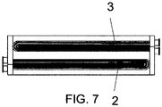
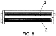
- tube bundles 2 and 3 may have a different shape and nature, such as conventional plain tubes, extended surface tubes, conventional longitudinal horizontal beams, as illustrated in Fig. 1 , U-type bundles (U-Bundle) ( Fig. 7 ) or a combination thereof mounted horizontally or vertically ( Fig. 8 , 9 ).
- buffered multi-fluid heat exchanger 1 with buffer fluid "T” is that boiling this fluid limits the temperature at which the hot "Q” or cold “F” fluids are subject to indirect contact; that is, the cold fluid conveying tubes or plates “F” will never “see” a temperature greater than the boiling temperature of the buffer fluid "T”; likewise, the hot fluid "Q” conveying tubes or plates will also not “see” temperatures below that of the buffer fluid "T” and evaporation.
- This feature allows this buffered multi-fluid heat exchanger 1 to process sensitive fluids or which may undergo decomposition or deterioration due to exposure to high or low temperatures.
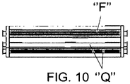
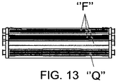
- the exchanger may utilize more than two process fluids: for example, two heating fluids "Q” and a cooling fluid "F” ( Fig. 10 ) or two cooling fluids “F” and one heating fluid ( Fig. 11 ), or two of each ( Fig. 12 ) or, in theory, provided that the mechanical construction of the equipment is feasible, as many fluids as desired ( Fig. 13 ).
- the technology described here can be used in any system where heating and cooling fluids is necessary, and where, for whatever reason, it is not desirable to have these fluids come into contact in case of a failure, or to limit the film temperature of one of the fluids.
- the buffered multi-fluid heat exchanger 1 performs a safety buffered multi-fluid heat exchange process, comprised essentially of:
Landscapes
- Engineering & Computer Science (AREA)
- Physics & Mathematics (AREA)
- Thermal Sciences (AREA)
- Mechanical Engineering (AREA)
- General Engineering & Computer Science (AREA)
- Geometry (AREA)
- Heat-Exchange Devices With Radiators And Conduit Assemblies (AREA)
Abstract
Description
- The present disclosure relates to a patent application for a buffered multi-fluid heat exchanger, and a multi-fluid heat exchange process, pertaining to the field of thermal exchange equipment and processes, which have been developed to provide increased safety, greater simplicity and lower cost over the conventional equipment and processes.
- In the chemical process industry, it is often necessary to heat or cool fluids in heat exchangers. These devices consist of vessels where two or more fluids indirectly contact with each other, and transfer heat from the hot fluid to the cold fluid.
- In various situations, these devices may be employed to chemically process incompatible fluids, whose contact can lead to exothermic chemical reactions, explosions, formation of by-products, unwanted products or even the loss of the products being heated or cooled.
- Typical examples of this type of situation is cooling sulfuric or phosphoric acid with water, substances which, when in direct contact react thoroughly and generate heat and an extremely corrosive dilute solution. Cooling hydrocarbons that are soluble between them may lead, in case they are mixed, to the production of hard-to-separate mixtures, and also loss of products and other similar situations.
- In some situations, it is a requirement that the cold fluid does not reach high temperatures in order to avoid its thermal decomposition. A typical example of this system are the reboilers of amines and glycols in the petrochemical industry.
- In order to avoid this kind of problem, the cooling process is usually carried out through systems featuring multiple heat exchangers in order to prevent contact of the fluids, in case of a malfunction, thus minimizing the damage that could be caused and preventing the cold fluid from being subjected to high temperatures that can cause their decomposition.
- This is the typical case of so-called "trim coolers" that are used, for example, in the sulfuric acid industry for heating boiler water (
Fig. 15 ). According to this arrangement, in case a heat exchanger shows a malfunction, the process fluids, i.e. sulfuric acid and deionized boiler water will not come into direct contact preventing boiler water contamination. - Another system that attempts to avoid this contact is disclosed in
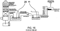
PCT BR 2016 050287 Fig. 16 ), and wherein, unlike conventional systems, the unit can be kept in operation or shutdown under normal regime. - For example, in the sulfuric acid industry, hot sulfuric acid at temperatures greater than 180° C is cooled in water boilers; the contact of these fluids under operating conditions resulted in important exothermic reactions with substantial damage to the equipment, and industrial assets, and compromising the safety of the operators.
- To avoid amine degradation in oil processing industry, the reboiler surface temperatures should be kept below 165 °C.
- An object of the present invention is to provide a new modeling for a heat exchange device (heat exchanger), which eliminates the need for systems featuring multiple heat exchangers ("trim coolers"), said heat exchanger using an intermediate fluid, called "buffer fluid."
- Another object of the invention is to provide a heat exchanger that carries out a reliable heat exchange between two or more incompatible process fluids, using a buffer fluid with suitable physicochemical characteristics with respect to the process fluids such that the operation safety is increased.
- Another object is to provide a heat exchanger that minimizes the cold fluid decomposition, using a buffer fluid with suitable physicochemical characteristics with respect to the process fluids such that a certain film temperature for the cold fluid is secured.
- Another object is to provide a heat exchanger that is relatively simple to build and manufacture.
- Another object is to provide a heat exchanger with low manufacturing, acquisition, operation and maintenance costs.
- Another object is to provide a thermal exchange process carried out by the heat exchanger.
- Another object is to provide a thermal exchange process that offers less cost, greater safety and operational simplifications than those using one or more heat exchangers that work with incompatible fluids.
- Therefore, in view of the shortcomings of the prior art, and in order to overcoming them and accomplishing the related objects of the invention, the heat exchanger of the present patent application has been developed, whose novel characteristic resides in that it utilizes three or more fluids, wherein two or more fluids are heating/cooling process fluids, and one fluid is a "buffer fluid" that conveys heat between the two or more process fluids; said buffer fluid being selected or formulated based on its characteristics of chemical compatibility with the other fluids, boiling temperature, viscosity, density, and chemical compatibility with the materials of the process equipment under operating conditions.
- In a system with three fluids, for example: a hot process fluid to be cooled, a cold process fluid to be heated and the buffer fluid, the safety buffered multi-fluid heat exchanger of the invention consists essentially of the following: a pressure vessel; two tube bundles through which the cold fluid and the hot fluid flow, parallel to and located inside the vessel; a space inside the vessel in which the tube bundles are arranged, and a buffer fluid portion that partially fills the inner space, and covers the tube bundle through which the heated process fluid flows, such that a heat exchange process substantially comprising the following steps is carried out: heat exchange of the hot process fluid with the buffer fluid; evaporation of the buffer fluid; heat exchange between the buffer fluid vapor and the cold process fluid; condensation of the buffer fluid; heat exchange between the condensed buffer fluid and the hot process fluid, and the start of a new cycle.
- The heat exchanger so constructed and the heat exchange process carried out by it overcome the above-mentioned shortcomings of the state of the art. Therefore, the heat exchanger so constructed and the heat exchange process carried out by it requires no systems with multiple heat exchangers, such as those used, for example, in the sulfuric acid industry for heating boiler water, as it prevents the direct contact of the process fluids, i.e. sulfuric acid and deionized boiler water, in case of malfunction of a heat exchanger, which could cause boiler water contamination, accelerated corrosion, and risk to safety due to hydrogen formation, and at the same time said heat exchanger and process have a relatively simpler construction, thus meeting the object of the invention.
- The heat exchanger so constructed and the heat exchange process carried out by it prevents the cold fluid from being subjected to high temperatures that could cause its decomposition, since, regardless of the temperature of the hot fluid, the cold fluid will only be subject to the boiling temperature of the buffer fluid, which will be selected to ensure this performance.
- The present heat exchanger and process is an alternative to the system described in
PCT BR 2016050287 - In addition to the above advantages, the present heat exchanger and process carried out by it have less manufacturing, acquisition, operation, and maintenance costs when compared to the state of the art, thus meeting other objects of the invention.
- The accompanying drawings relate to the safety buffered multi-fluid heat exchanger, and safety buffered multi-fluid heat exchange process, objects of the present patent, in which:
-
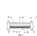
Fig. 1 shows a schematic view of the safety bufferedmulti-fluid heat exchanger 1; -
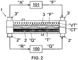
Fig. 2 shows the samefigure 1 illustrating the operation of theheat exchanger 1; -
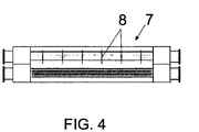
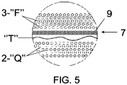
Figs. 3-6 show various embodiments of adevice 7 for reducing the loss of efficiency in the region of contact between the vapor and buffer fluid "T" condensate; -
Figs. 7-9 showvarious tubing constructions 2 for the hot fluid "Q" to be cooled andtubing 3 for the cold fluid "F" to be heated, which form part ofheat exchanger 1; -
Figs. 10-13 show variations of the amounts of process fluids that may be provided in theheat exchanger 1; -
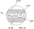
Fig. 14 shows a schematic view of the heat exchange process carried out by theheat exchanger 1 of the previous figures; -
Fig. 15 shows a schematic view of the "trim coolers" process of the art; and -
Fig. 16 shows a schematic view of one of the possibilities of the equipment disclosed in the co-pendingPCT BR 2016/050287 - As illustrated in the above figures, the buffered
multi-fluid heat exchanger 1, object of the present invention, is intended for heat exchange between a hot process fluid to be cooled and a cold process fluid to be heated, particularly when these fluids are chemically incompatible with each other, and which, when in contact, could generate exothermic chemical reactions, explosions, formation of undesirable by-products or the loss of the products being heated and cooled or, in case it is interesting or required to ensure a maximum film temperature for the cold fluid to preserve its quality or other characteristics. - Thus, said buffered
multi-fluid heat exchanger 1 comprises (Fig. 1 ): alower tubing 2 through which a hot process fluid "Q" to be cooled circulates; atubing 3, through which a cold process fluid "F" to be heated circulates, superior, parallel and spaced relative to thelower tubing 2; avessel 4 containing saidtubing outlet 2" nozzles communicating with respective ends of thetubing 2 through which a hot process fluid "Q" to be cooled circulates, inlet 3' andoutlet 3" nozzles communicating with respective ends of thetubing 3, through which a cold process fluid "F" to be heated circulates; saidnozzles 2', 2", 3', 3" connected to tubing connected todevices 100, 101 (Fig. 2 ) using the cold process fluid "R" from the hot process fluid "Q", and the hot process fluid "A" from the cold process fluid "F"; said bufferedmulti-fluid heat exchanger 1 being further comprised by a buffer fluid "T" portion, which fills part of thevessel 4, and covers thelower tubing 2 through which a hot process fluid "Q" to be cooled circulates. - In detail,
tubing tubing - The equipment is provided with inlet 2', 3' and
outlet 2", 3" nozzles of the hot "Q" and cold "F" process fluids, feeding 5 and draining 6 nozzles for the buffer fluid "T", nozzles for instruments, pressure relief valves and the like (not shown) in accordance with all of the good industrial practices and technical standards of the various countries. - Buffer fluid "T" is selected because of its chemical compatibility and boiling temperature in connection with the process fluids "Q" and "F" and its physicochemical characteristics.
- The principle of operation of the buffered
multi-fluid heat exchanger 1 is extremely simple and benefits from the high heat transfer coefficients obtained during boiling and condensation processes, when compared to the heat transfer coefficients obtained from convection systems. - Thus, (
Fig. 2 ) hot fluid "Q" is received by its inlet nozzle 2' and passes through thetube bundle 2; as this occurs, such fluid transfers heat to the buffer fluid "T", which occupies part of the chamber formed byvessel 4 of theheat exchanger 1. Buffer fluid "T", which has been chosen because of its chemical compatibility and boiling temperature relative to the process fluids "Q" and "F", and its physicochemical characteristics, boils and forms part of the buffer fluid "VT", removing heat from the hot fluid "Q", which is thus cooled and constitutes the cooled fluid "R", which leaves thetube bundle 2 through theoutlet nozzles 2", and is fed into theequipment 100 using the cooled fluid "R", at the end of which the fluid turns back into hot process fluid "Q", which is fed back, through inlet nozzles 2', into the bufferedmulti-fluid heat exchanger 1 and the cycle restarts. - The same occurs substantially with respect to cold fluid "F". Thus, cold fluid "F" is received through its inlet nozzles 3' and passes through
tube bundle 3; as this occurs, such fluid receives heat from the buffer fluid vapor "VT", which condenses, forming the buffer fluid "CT" condensate, that is, the buffer fluid "T" returns to the liquid phase, during which heat is transferred to the cold fluid "F", which is thus heated and becomes hot fluid "A", which leaves thetube bundle 3 throughoutlet nozzle 3", and is fed into thedevice 101 using hot fluid "A", at the end of which the fluid turns back into cold process fluid "F", which is fed back through inlet nozzle 3' in the bufferedmulti-fluid heat exchanger 1, and the cycle restarts. - Vapors "VT" resulting from buffer fluid "T" boiling in contact with
pipe 2, in which hot fluid "Q" circulates, rise and reach thetube bundle 3 where cold fluid "F" is transported. - Upon reaching this
tube bundle 3, where the cold fluid "F" passes, the buffer fluid vapor "VT" is condensed forming buffer fluid "CT" condensate, (buffer fluid "T" in liquid phase) which returns to the buffer fluid body "T" where it is evaporated again by the hot process fluid "Q". The process continues indefinitely. - During this operation, the buffer fluid vapors "VT" rise from boiling in the
hot fluid bundle 2, contact the buffer fluid "CT" condensate coming from the cold fluid bundle 3 (upper). - In this movement, some heat exchange may occur between the vapors and buffer fluid "T" droplets, although small, since vapors and liquid are at the same temperature, and therefore the heat transfer driving force is impaired. To eliminate or minimize this effect, a
device 7 can be provided to reduce the loss of efficiency in the region of contact between the vapor and buffer fluid "T" condensate. According to one embodiment, thisdevice 7 can consist of theupper tube bundles 3, through which the cold fluid "F" to be heated flows, which may be tilted (Fig. 3 ) or provided with baffles 8 (Fig. 4 ) to accelerate and direct draining and the condensate. - In another embodiment, this
device 7 for reducing the loss of efficiency in the region of contact between the vapor and buffer fluid "T" condensate can consist of gas-liquid separating devices, such as fins, Chevron type separators 9 (Fig. 5 ) or baffle fins 10 (Fig. 6 ) or others set up in the region between the lower 2 and the top 3 tube bundles, where hot "Q" and cold "F" fluids circulate, respectively. - According to the basic construction described above, the buffered
multi-fluid heat exchanger 1 object of the present invention may be subject to changes in materials, dimensions, constructive details and/or functional and configuration without departing from the scope of the protection claimed. - In addition, the
tube bundles Fig. 1 , U-type bundles (U-Bundle) (Fig. 7 ) or a combination thereof mounted horizontally or vertically (Fig. 8 ,9 ). - An important change with respect to conventional exchangers is that in the present buffer
fluid heat exchanger 1 with buffer fluid "T", there is no characterization of competing flow, counter-current, cross flow, and other arrangements. The buffer fluid "T" inside the equipment is at its boiling temperature in the process condition, so that the totality of the fluid along the entire length oftubular bundles outlet nozzles 2", 3" of the equipment andtubular bundles - Another important advantage that can be achieved with a buffered
multi-fluid heat exchanger 1 with buffer fluid "T" is that boiling this fluid limits the temperature at which the hot "Q" or cold "F" fluids are subject to indirect contact; that is, the cold fluid conveying tubes or plates "F" will never "see" a temperature greater than the boiling temperature of the buffer fluid "T"; likewise, the hot fluid "Q" conveying tubes or plates will also not "see" temperatures below that of the buffer fluid "T" and evaporation. This feature allows this bufferedmulti-fluid heat exchanger 1 to process sensitive fluids or which may undergo decomposition or deterioration due to exposure to high or low temperatures. - The exchanger may utilize more than two process fluids: for example, two heating fluids "Q" and a cooling fluid "F" (
Fig. 10 ) or two cooling fluids "F" and one heating fluid (Fig. 11 ), or two of each (Fig. 12 ) or, in theory, provided that the mechanical construction of the equipment is feasible, as many fluids as desired (Fig. 13 ). - The proposed devices have been originally conceived to reduce the volume of inert fluid/buffer in indirect sulfuric acid cooling systems as disclosed in the patent application (US Patent Application No.
PCT BR 2016 050287 - However, the technology described here can be used in any system where heating and cooling fluids is necessary, and where, for whatever reason, it is not desirable to have these fluids come into contact in case of a failure, or to limit the film temperature of one of the fluids.
- The buffered
multi-fluid heat exchanger 1, as described above, performs a safety buffered multi-fluid heat exchange process, comprised essentially of: - providing a
lower tube 2 through which a hot process fluid "Q" to be cooled flows; - providing an
upper tube 3 through which a cool process fluid "F" to be heated flows, parallel, and which keeps a space with respect to thelower tube 2; - providing an
airtight vessel 4 inside which tube bodies (2), (3) are housed and connected to inlet nozzles 2', 3' andoutlet nozzles 2", 3", respectively; - providing a portion of the heat transferring buffer fluid "T", inert in relation to hot "Q" and cold "F" fluids, which partially fills
vessel 4 and which covers thelower tube 2, through which hot fluid "Q" to be cooled circulates; - providing the steps of (
Fig. 2 ,14 ): - Circulation of the hot fluid "Q" to be cooled in the
lower tube 2 and circulation of the cold fluid "F" to be heated in theupper tube 3; - Heat exchange between the buffer fluid "T" and the hot fluid "Q" to be cooled flowing in the
lower tubing 2 and vaporizing the buffer fluid "T", forming cooled fluid "R" and fluid vapor "VT"; - Upward movement of the buffer fluid vapor "VT" until reaching and contacting the
upper tube 3 through which the cold fluid "F" to be heated flows; - Heat exchange between the buffer fluid vapor "VT" and the cool fluid "F" to be heated flowing in the
upper tube 3, and condensing the buffer fluid vapor "VT", forming heated fluid "A" and buffered fluid "CT" condensate; - Downward movement of the buffer fluid "CT" condensate until it joins the buffer fluid "T" body in the liquid phase and restarting the cycle.
- Step of reducing efficiency loss in the contact region between the ascending vapor "VT" and the descending condensate "CT" of fluid buffer "T", taken in the space between
tubing 2 through which the hot process fluid "Q" circulates, andtubing 3 through which the cold process fluid "F" circulates.
Claims (8)
- "SAFETY BUFFERED MULTI-FLUID HEAT EXCHANGER", comprising tubing (2) through which the hot process fluid "Q" to be cooled flows, tubing (3) through which the cold process fluid "F" to be heated flows, characterized by a lower tubing (2) through which the hot process flow "Q" to be cooled circulates; tubing (3) through which the cold process fluid "F" to be heated flows, superior, parallel and spaced relative to the lower tubing (2); a vessel (4) containing tubing (2) and (3) having opposite inlet (2'), and outlet (2") nozzles communicating with the respective ends of the tubing (2), opposite inlet (3') and outlet (3") nozzles communicating with the respective ends of the tubing (3); said nozzles (2)', (2)", (3)',(3)" connected to tubing connected to the equipment (100), (101) which use the cold process fluid "R" coming from the hot process fluid "Q" and the hot process fluid "A" coming from the cold process fluid "F"; said buffered multi-fluid heat exchanger (1) further comprising a buffer fluid "T" portion that fills part of the vessel (4), and covers the lower tubing (2) through which the hot process fluid "Q" to be cooled circulates.
- "SAFETY BUFFERED MULTI-FLUID HEAT EXCHANGER", according to claim 1, characterized in that tubing (2) and (3) comprise smooth, finned tubular bundles with longitudinal fins, circumferential fins, helical fins, twisted tubes suitable to promote and maximize the thermal exchange between the hot "Q" and cold "F" fluids circulating in tubing (2) and (3) respectively, and the buffer fluid "T".
- "SAFETY BUFFERED MULTI-FLUID HEAT EXCHANGER", according to claim 1, characterized in that the buffered fluid "T" is selected based on its chemical compatibility with the process fluids "Q" and "F" and their physicochemical characteristics.
- "SAFETY BUFFERED MULTI-FLUID HEAT EXCHANGER", according to claim 1, characterized in that the device (7) to reduce loss of efficiency in the contact region between the vapor and the buffer fluid "T" condensate, comprising upper tube bundles (3) through which the cold fluid "F" to be heated flows, is tilted or provided with baffles (8) or said device (7) to reduce loss of efficiency in the contact region between the vapor and the buffer fluid "T" condensate may comprise gas-liquid separating devices, such as fins, Chevron separators (9) or baffle fins (10) set up in the region between the lower (2) and upper (3) tube bundles, where the hot "Q" and cold ""F" fluids circulate, respectively.
- "SAFETY BUFFERED MULTI-FLUID HEAT EXCHANGER", according to claim 1 or 2, characterized in that tubing (2) and (3) are horizontal, longitudinal, transversal tube bundles (2) and (3), U bundles (U-Bundle) or a combination thereof mounted horizontally or vertically
- "SAFETY BUFFERED MULTI-FLUID HEAT EXCHANGER", according to claim 1, characterized in that it may utilize more than two process fluids, such as: two heating fluids "Q" and a cooling fluid "F" or two cooling fluids "F" and a heating fluid or two of each or as many fluids as desired and that the mechanical construction of the equipment allows.
- "SAFETY BUFFERED MULTI-FLUID HEAT EXCHANGE PROCESS", carried out by the heat exchanger (1) as claimed in claims 1-6, characterized by:- providing a lower tubing (2) through which a hot process fluid "Q" to be cooled flows;- providing an upper tubing (3) through which a cool process fluid "F" to be heated flows, parallel, and which keeps a space with respect to the lower tubing (2);- providing an airtight vessel (4) inside which tube bodies (2), (3) are housed and connected to inlet (2'), (3') and outlet (2"), (3") nozzles, respectively;- providing a portion of the heat transferring buffer fluid "T", inert in relation to hot "Q" and cold "F" fluids, which partially fills vessel (4) and which covers the lower tubing (2), through which hot fluid "Q" to be cooled circulates;- providing the steps of:- Circulation of the hot fluid "Q" to be cooled in the lower tubing (2) and circulation of the cold fluid "F" to be heated in the upper tubing (3);- Heat exchange between the buffer fluid "T" and the hot fluid "Q" to be cooled flowing in the lower tubing (2) and vaporizing the buffer fluid "T", forming cooled fluid "R" and buffer fluid vapor "T";- Upward movement of the buffer fluid vapor "VT" until reaching and contacting the upper tubing (3) through which the cold fluid "F" to be heated flows;- Heat exchange between the buffer fluid vapor "VT" and the cool fluid "F" to be heated flowing in the upper tubing (3), and condensing the buffer fluid vapor "VT", forming heated fluid "A" and buffered fluid condensate "CT";- Downward movement of the buffer fluid condensate "CT" until it joins the buffer fluid "T" body in the liquid phase and restarting the cycle.
- "SAFETY BUFFERED MULTI-FLUID HEAT EXCHANGE PROCESS", according to claim 7, characterized in that it comprises a step to reduce loss of efficiency in the contact region between the ascending vapor "VT" and the descending condensate "CT" of the buffer fluid "T" performed in the space between tubing (2) through which the hot process fluid "Q" circulates, and tubing (3) through which the cold process fluid "F" circulates, performed by the upper, longitudinal, transversal, flat or tilted tubing (3), and/or featuring baffles (8) or gas-liquid separating devices, such as fins, Chevron separators (9) or baffle fins (10) mounted in the region between the lower (2) and upper (3) tube bundles, where the hot "Q" and cold ""F" fluids circulate, respectively.
Applications Claiming Priority (2)
| Application Number | Priority Date | Filing Date | Title |
|---|---|---|---|
| BR102019020293-9A BR102019020293B1 (en) | 2019-09-27 | SAFETY BUFFRED MULTIFLUID HEAT EXCHANGER AND SAFETY BUFFRED MULTIFLUID THERMAL EXCHANGE PROCESS | |
| PCT/BR2020/050380 WO2021056089A1 (en) | 2019-09-27 | 2020-09-25 | Safety buffered multi-fluid heat exchanger and safety buffered multi-fluid heat exchange process |
Publications (2)
| Publication Number | Publication Date |
|---|---|
| EP4043820A1 true EP4043820A1 (en) | 2022-08-17 |
| EP4043820A4 EP4043820A4 (en) | 2023-10-25 |
Family
ID=72241957
Family Applications (1)
| Application Number | Title | Priority Date | Filing Date |
|---|---|---|---|
| EP20870147.4A Withdrawn EP4043820A4 (en) | 2019-09-27 | 2020-09-25 | SAFETY BUFFERED MULTI-LUID HEAT EXCHANGER AND SAFETY BUFFERED MULTI-LUID HEAT EXCHANGE METHOD |
Country Status (3)
| Country | Link |
|---|---|
| US (1) | US11604031B2 (en) |
| EP (1) | EP4043820A4 (en) |
| WO (1) | WO2021056089A1 (en) |
Families Citing this family (1)
| Publication number | Priority date | Publication date | Assignee | Title |
|---|---|---|---|---|
| CN114383442A (en) * | 2021-12-14 | 2022-04-22 | 浙江银轮新能源热管理系统有限公司 | Heat exchanger and motor vehicle air conditioning system |
Family Cites Families (8)
| Publication number | Priority date | Publication date | Assignee | Title |
|---|---|---|---|---|
| DE2753483A1 (en) * | 1977-12-01 | 1979-06-07 | Linde Ag | Heat exchanger using heat transmitting fluid - in which evaporated part of heat transmitting fluid is brought into heat exchange with second fluid |
| US5103899A (en) * | 1990-08-31 | 1992-04-14 | Kalina Alexander Ifaevich | Multi-flow tubular heat exchanger |
| FR2704939B1 (en) * | 1993-05-06 | 1995-06-23 | Valeo Thermique Habitacle | Refrigerant circuit with improved efficiency. |
| CA2186557A1 (en) | 1995-09-29 | 1997-03-30 | Brian M. Burmaster | Double-segmental shell and tube heat exchanger |
| EP2213367A4 (en) * | 2007-10-19 | 2014-05-07 | Lou Ren | A composite reaction apparatus and the chemical production method using the same |
| DE102010006541B4 (en) | 2010-02-01 | 2016-03-17 | Outotec Oyj | Method and apparatus for cooling acid |
| CN204142047U (en) | 2014-09-19 | 2015-02-04 | 东晨阳光(北京)太阳能科技有限公司 | Tubular type gas-liquid heat-exchange |
| BR102016003690B1 (en) * | 2016-02-22 | 2022-08-30 | Nc Engenharia, Industria E Comercio Ltda | METHOD AND EQUIPMENT FOR COOLING SULFURIC ACID |
-
2020
- 2020-09-25 WO PCT/BR2020/050380 patent/WO2021056089A1/en not_active Ceased
- 2020-09-25 EP EP20870147.4A patent/EP4043820A4/en not_active Withdrawn
- 2020-09-25 US US17/636,442 patent/US11604031B2/en active Active
Also Published As
| Publication number | Publication date |
|---|---|
| EP4043820A4 (en) | 2023-10-25 |
| BR102019020293A2 (en) | 2020-08-11 |
| US20220290923A1 (en) | 2022-09-15 |
| WO2021056089A1 (en) | 2021-04-01 |
| US11604031B2 (en) | 2023-03-14 |
Similar Documents
| Publication | Publication Date | Title |
|---|---|---|
| US5452758A (en) | Heat exchanger | |
| US5027891A (en) | Method for transferring heat between process liquor streams | |
| WO2016047185A1 (en) | Evaporator and refrigerator | |
| US11604031B2 (en) | Safety buffered multi-fluid heat exchanger and safety buffered multi-fluid heat exchange process | |
| US20130075064A1 (en) | Heat Exchanger | |
| US6178293B1 (en) | Method and an apparatus for improving heat transfer | |
| RU2676167C2 (en) | Heat exchanger, including heat exchanger reactor system and method for thermostating reactor | |
| BR112020004786A2 (en) | heat exchanger and process to transfer heat | |
| EP4542112A1 (en) | Method for preparing steam or hot water using waste heat of cooling water | |
| CN111375220B (en) | Gas-liquid separation and recovery device | |
| KR101700753B1 (en) | Steam generator and nuclear power plant having the same | |
| CN121220191A (en) | Cooling systems for liquid immersion cooling of electronic components | |
| US1846955A (en) | Heat exchange apparatus | |
| BR102019020293B1 (en) | SAFETY BUFFRED MULTIFLUID HEAT EXCHANGER AND SAFETY BUFFRED MULTIFLUID THERMAL EXCHANGE PROCESS | |
| RU2594449C1 (en) | Vertical shell and tube heat exchanger with condensation of vapours in annular space | |
| KR102305400B1 (en) | Vapor and liquid drums for shell-and-tube heat exchangers | |
| JP4644631B2 (en) | Absorption heat pump | |
| KR20210108922A (en) | Heat exchanger | |
| KR20040074263A (en) | Heat exchanger having multiful heat pipe | |
| KR200349474Y1 (en) | Thermosiphon Heat Pipe Type Heat Exchanger | |
| Bhoyar et al. | Tube Failure Prevention of Heat Exchanger | |
| KR102307564B1 (en) | Containment cooling system having improved cooling performance | |
| NO348914B1 (en) | Heat Pump | |
| US20140048237A1 (en) | Shell and tube heat exchanger | |
| Taborek | Selected problems in heat exchanger design |
Legal Events
| Date | Code | Title | Description |
|---|---|---|---|
| STAA | Information on the status of an ep patent application or granted ep patent |
Free format text: STATUS: THE INTERNATIONAL PUBLICATION HAS BEEN MADE |
|
| PUAI | Public reference made under article 153(3) epc to a published international application that has entered the european phase |
Free format text: ORIGINAL CODE: 0009012 |
|
| STAA | Information on the status of an ep patent application or granted ep patent |
Free format text: STATUS: REQUEST FOR EXAMINATION WAS MADE |
|
| 17P | Request for examination filed |
Effective date: 20220221 |
|
| AK | Designated contracting states |
Kind code of ref document: A1 Designated state(s): AL AT BE BG CH CY CZ DE DK EE ES FI FR GB GR HR HU IE IS IT LI LT LU LV MC MK MT NL NO PL PT RO RS SE SI SK SM TR |
|
| DAV | Request for validation of the european patent (deleted) | ||
| DAX | Request for extension of the european patent (deleted) | ||
| A4 | Supplementary search report drawn up and despatched |
Effective date: 20230922 |
|
| RIC1 | Information provided on ipc code assigned before grant |
Ipc: F28D 7/16 20060101ALI20230918BHEP Ipc: F28D 7/06 20060101ALI20230918BHEP Ipc: F28D 20/02 20060101ALI20230918BHEP Ipc: F28D 7/00 20060101ALI20230918BHEP Ipc: F28D 15/02 20060101AFI20230918BHEP |
|
| STAA | Information on the status of an ep patent application or granted ep patent |
Free format text: STATUS: THE APPLICATION IS DEEMED TO BE WITHDRAWN |
|
| 18D | Application deemed to be withdrawn |
Effective date: 20240423 |