EP4043778B1 - Anzeigevorrichtung - Google Patents
Anzeigevorrichtung Download PDFInfo
- Publication number
- EP4043778B1 EP4043778B1 EP19948222.5A EP19948222A EP4043778B1 EP 4043778 B1 EP4043778 B1 EP 4043778B1 EP 19948222 A EP19948222 A EP 19948222A EP 4043778 B1 EP4043778 B1 EP 4043778B1
- Authority
- EP
- European Patent Office
- Prior art keywords
- link
- display device
- spacer
- frame
- display module
- Prior art date
- Legal status (The legal status is an assumption and is not a legal conclusion. Google has not performed a legal analysis and makes no representation as to the accuracy of the status listed.)
- Active
Links
Images









Classifications
-
- G—PHYSICS
- G06—COMPUTING OR CALCULATING; COUNTING
- G06F—ELECTRIC DIGITAL DATA PROCESSING
- G06F1/00—Details not covered by groups G06F3/00 - G06F13/00 and G06F21/00
- G06F1/16—Constructional details or arrangements
- G06F1/1601—Constructional details related to the housing of computer displays, e.g. of CRT monitors, of flat displays
- G06F1/1607—Arrangements to support accessories mechanically attached to the display housing
-
- F—MECHANICAL ENGINEERING; LIGHTING; HEATING; WEAPONS; BLASTING
- F16—ENGINEERING ELEMENTS AND UNITS; GENERAL MEASURES FOR PRODUCING AND MAINTAINING EFFECTIVE FUNCTIONING OF MACHINES OR INSTALLATIONS; THERMAL INSULATION IN GENERAL
- F16M—FRAMES, CASINGS OR BEDS OF ENGINES, MACHINES OR APPARATUS, NOT SPECIFIC TO ENGINES, MACHINES OR APPARATUS PROVIDED FOR ELSEWHERE; STANDS; SUPPORTS
- F16M11/00—Stands or trestles as supports for apparatus or articles placed thereon ; Stands for scientific apparatus such as gravitational force meters
- F16M11/02—Heads
- F16M11/04—Means for attachment of apparatus; Means allowing adjustment of the apparatus relatively to the stand
- F16M11/041—Allowing quick release of the apparatus
-
- F—MECHANICAL ENGINEERING; LIGHTING; HEATING; WEAPONS; BLASTING
- F16—ENGINEERING ELEMENTS AND UNITS; GENERAL MEASURES FOR PRODUCING AND MAINTAINING EFFECTIVE FUNCTIONING OF MACHINES OR INSTALLATIONS; THERMAL INSULATION IN GENERAL
- F16M—FRAMES, CASINGS OR BEDS OF ENGINES, MACHINES OR APPARATUS, NOT SPECIFIC TO ENGINES, MACHINES OR APPARATUS PROVIDED FOR ELSEWHERE; STANDS; SUPPORTS
- F16M11/00—Stands or trestles as supports for apparatus or articles placed thereon ; Stands for scientific apparatus such as gravitational force meters
- F16M11/02—Heads
- F16M11/04—Means for attachment of apparatus; Means allowing adjustment of the apparatus relatively to the stand
- F16M11/06—Means for attachment of apparatus; Means allowing adjustment of the apparatus relatively to the stand allowing pivoting
- F16M11/10—Means for attachment of apparatus; Means allowing adjustment of the apparatus relatively to the stand allowing pivoting around a horizontal axis
- F16M11/105—Means for attachment of apparatus; Means allowing adjustment of the apparatus relatively to the stand allowing pivoting around a horizontal axis the horizontal axis being the roll axis, e.g. for creating a landscape-portrait rotation
-
- F—MECHANICAL ENGINEERING; LIGHTING; HEATING; WEAPONS; BLASTING
- F16—ENGINEERING ELEMENTS AND UNITS; GENERAL MEASURES FOR PRODUCING AND MAINTAINING EFFECTIVE FUNCTIONING OF MACHINES OR INSTALLATIONS; THERMAL INSULATION IN GENERAL
- F16M—FRAMES, CASINGS OR BEDS OF ENGINES, MACHINES OR APPARATUS, NOT SPECIFIC TO ENGINES, MACHINES OR APPARATUS PROVIDED FOR ELSEWHERE; STANDS; SUPPORTS
- F16M11/00—Stands or trestles as supports for apparatus or articles placed thereon ; Stands for scientific apparatus such as gravitational force meters
- F16M11/02—Heads
- F16M11/04—Means for attachment of apparatus; Means allowing adjustment of the apparatus relatively to the stand
- F16M11/06—Means for attachment of apparatus; Means allowing adjustment of the apparatus relatively to the stand allowing pivoting
- F16M11/12—Means for attachment of apparatus; Means allowing adjustment of the apparatus relatively to the stand allowing pivoting in more than one direction
- F16M11/126—Means for attachment of apparatus; Means allowing adjustment of the apparatus relatively to the stand allowing pivoting in more than one direction for tilting and panning
-
- F—MECHANICAL ENGINEERING; LIGHTING; HEATING; WEAPONS; BLASTING
- F16—ENGINEERING ELEMENTS AND UNITS; GENERAL MEASURES FOR PRODUCING AND MAINTAINING EFFECTIVE FUNCTIONING OF MACHINES OR INSTALLATIONS; THERMAL INSULATION IN GENERAL
- F16M—FRAMES, CASINGS OR BEDS OF ENGINES, MACHINES OR APPARATUS, NOT SPECIFIC TO ENGINES, MACHINES OR APPARATUS PROVIDED FOR ELSEWHERE; STANDS; SUPPORTS
- F16M11/00—Stands or trestles as supports for apparatus or articles placed thereon ; Stands for scientific apparatus such as gravitational force meters
- F16M11/02—Heads
- F16M11/18—Heads with mechanism for moving the apparatus relatively to the stand
-
- F—MECHANICAL ENGINEERING; LIGHTING; HEATING; WEAPONS; BLASTING
- F16—ENGINEERING ELEMENTS AND UNITS; GENERAL MEASURES FOR PRODUCING AND MAINTAINING EFFECTIVE FUNCTIONING OF MACHINES OR INSTALLATIONS; THERMAL INSULATION IN GENERAL
- F16M—FRAMES, CASINGS OR BEDS OF ENGINES, MACHINES OR APPARATUS, NOT SPECIFIC TO ENGINES, MACHINES OR APPARATUS PROVIDED FOR ELSEWHERE; STANDS; SUPPORTS
- F16M11/00—Stands or trestles as supports for apparatus or articles placed thereon ; Stands for scientific apparatus such as gravitational force meters
- F16M11/20—Undercarriages with or without wheels
- F16M11/2007—Undercarriages with or without wheels comprising means allowing pivoting adjustment
- F16M11/2014—Undercarriages with or without wheels comprising means allowing pivoting adjustment around a vertical axis
-
- F—MECHANICAL ENGINEERING; LIGHTING; HEATING; WEAPONS; BLASTING
- F16—ENGINEERING ELEMENTS AND UNITS; GENERAL MEASURES FOR PRODUCING AND MAINTAINING EFFECTIVE FUNCTIONING OF MACHINES OR INSTALLATIONS; THERMAL INSULATION IN GENERAL
- F16M—FRAMES, CASINGS OR BEDS OF ENGINES, MACHINES OR APPARATUS, NOT SPECIFIC TO ENGINES, MACHINES OR APPARATUS PROVIDED FOR ELSEWHERE; STANDS; SUPPORTS
- F16M11/00—Stands or trestles as supports for apparatus or articles placed thereon ; Stands for scientific apparatus such as gravitational force meters
- F16M11/20—Undercarriages with or without wheels
- F16M11/2007—Undercarriages with or without wheels comprising means allowing pivoting adjustment
- F16M11/2035—Undercarriages with or without wheels comprising means allowing pivoting adjustment in more than one direction
-
- F—MECHANICAL ENGINEERING; LIGHTING; HEATING; WEAPONS; BLASTING
- F16—ENGINEERING ELEMENTS AND UNITS; GENERAL MEASURES FOR PRODUCING AND MAINTAINING EFFECTIVE FUNCTIONING OF MACHINES OR INSTALLATIONS; THERMAL INSULATION IN GENERAL
- F16M—FRAMES, CASINGS OR BEDS OF ENGINES, MACHINES OR APPARATUS, NOT SPECIFIC TO ENGINES, MACHINES OR APPARATUS PROVIDED FOR ELSEWHERE; STANDS; SUPPORTS
- F16M11/00—Stands or trestles as supports for apparatus or articles placed thereon ; Stands for scientific apparatus such as gravitational force meters
- F16M11/20—Undercarriages with or without wheels
- F16M11/2092—Undercarriages with or without wheels comprising means allowing depth adjustment, i.e. forward-backward translation of the head relatively to the undercarriage
-
- F—MECHANICAL ENGINEERING; LIGHTING; HEATING; WEAPONS; BLASTING
- F16—ENGINEERING ELEMENTS AND UNITS; GENERAL MEASURES FOR PRODUCING AND MAINTAINING EFFECTIVE FUNCTIONING OF MACHINES OR INSTALLATIONS; THERMAL INSULATION IN GENERAL
- F16M—FRAMES, CASINGS OR BEDS OF ENGINES, MACHINES OR APPARATUS, NOT SPECIFIC TO ENGINES, MACHINES OR APPARATUS PROVIDED FOR ELSEWHERE; STANDS; SUPPORTS
- F16M13/00—Other supports for positioning apparatus or articles; Means for steadying hand-held apparatus or articles
- F16M13/02—Other supports for positioning apparatus or articles; Means for steadying hand-held apparatus or articles for supporting on, or attaching to, an object, e.g. tree, gate, window-frame, cycle
-
- G—PHYSICS
- G02—OPTICS
- G02F—OPTICAL DEVICES OR ARRANGEMENTS FOR THE CONTROL OF LIGHT BY MODIFICATION OF THE OPTICAL PROPERTIES OF THE MEDIA OF THE ELEMENTS INVOLVED THEREIN; NON-LINEAR OPTICS; FREQUENCY-CHANGING OF LIGHT; OPTICAL LOGIC ELEMENTS; OPTICAL ANALOGUE/DIGITAL CONVERTERS
- G02F1/00—Devices or arrangements for the control of the intensity, colour, phase, polarisation or direction of light arriving from an independent light source, e.g. switching, gating or modulating; Non-linear optics
- G02F1/01—Devices or arrangements for the control of the intensity, colour, phase, polarisation or direction of light arriving from an independent light source, e.g. switching, gating or modulating; Non-linear optics for the control of the intensity, phase, polarisation or colour
- G02F1/13—Devices or arrangements for the control of the intensity, colour, phase, polarisation or direction of light arriving from an independent light source, e.g. switching, gating or modulating; Non-linear optics for the control of the intensity, phase, polarisation or colour based on liquid crystals, e.g. single liquid crystal display cells
- G02F1/133—Constructional arrangements; Operation of liquid crystal cells; Circuit arrangements
- G02F1/1333—Constructional arrangements; Manufacturing methods
- G02F1/133308—Support structures for LCD panels, e.g. frames or bezels
-
- F—MECHANICAL ENGINEERING; LIGHTING; HEATING; WEAPONS; BLASTING
- F16—ENGINEERING ELEMENTS AND UNITS; GENERAL MEASURES FOR PRODUCING AND MAINTAINING EFFECTIVE FUNCTIONING OF MACHINES OR INSTALLATIONS; THERMAL INSULATION IN GENERAL
- F16B—DEVICES FOR FASTENING OR SECURING CONSTRUCTIONAL ELEMENTS OR MACHINE PARTS TOGETHER, e.g. NAILS, BOLTS, CIRCLIPS, CLAMPS, CLIPS OR WEDGES; JOINTS OR JOINTING
- F16B21/00—Means for preventing relative axial movement of a pin, spigot, shaft or the like and a member surrounding it; Stud-and-socket releasable fastenings
- F16B21/09—Releasable fastening devices with a stud engaging a keyhole slot
-
- F—MECHANICAL ENGINEERING; LIGHTING; HEATING; WEAPONS; BLASTING
- F16—ENGINEERING ELEMENTS AND UNITS; GENERAL MEASURES FOR PRODUCING AND MAINTAINING EFFECTIVE FUNCTIONING OF MACHINES OR INSTALLATIONS; THERMAL INSULATION IN GENERAL
- F16M—FRAMES, CASINGS OR BEDS OF ENGINES, MACHINES OR APPARATUS, NOT SPECIFIC TO ENGINES, MACHINES OR APPARATUS PROVIDED FOR ELSEWHERE; STANDS; SUPPORTS
- F16M2200/00—Details of stands or supports
- F16M2200/06—Arms
-
- G—PHYSICS
- G02—OPTICS
- G02F—OPTICAL DEVICES OR ARRANGEMENTS FOR THE CONTROL OF LIGHT BY MODIFICATION OF THE OPTICAL PROPERTIES OF THE MEDIA OF THE ELEMENTS INVOLVED THEREIN; NON-LINEAR OPTICS; FREQUENCY-CHANGING OF LIGHT; OPTICAL LOGIC ELEMENTS; OPTICAL ANALOGUE/DIGITAL CONVERTERS
- G02F1/00—Devices or arrangements for the control of the intensity, colour, phase, polarisation or direction of light arriving from an independent light source, e.g. switching, gating or modulating; Non-linear optics
- G02F1/01—Devices or arrangements for the control of the intensity, colour, phase, polarisation or direction of light arriving from an independent light source, e.g. switching, gating or modulating; Non-linear optics for the control of the intensity, phase, polarisation or colour
- G02F1/13—Devices or arrangements for the control of the intensity, colour, phase, polarisation or direction of light arriving from an independent light source, e.g. switching, gating or modulating; Non-linear optics for the control of the intensity, phase, polarisation or colour based on liquid crystals, e.g. single liquid crystal display cells
- G02F1/133—Constructional arrangements; Operation of liquid crystal cells; Circuit arrangements
- G02F1/1333—Constructional arrangements; Manufacturing methods
- G02F1/133308—Support structures for LCD panels, e.g. frames or bezels
- G02F1/133314—Back frames
Definitions
- the present disclosure relates to a display device.
- LCD liquid crystal display
- PDP plasma display panel
- ELD electroluminescent display
- VFD vacuum fluorescent display
- a display device may include a display module that displays an input image.
- the display module may be provided by combining a display panel and a case member for fixing the display panel.
- the display module can be used by being hung on a fixed object such as a wall or by being supported on a stand and placed on a floor. In order to hang the display module on a fixed object, a wall mount assembly is required.
- KR 100 962 008 B1 , US 2013/168519 A1 and US 2018/324961 A1 represent prior art useful for understanding the invention.
- a display device includes: a display module including a display panel: at least one pair of first and second spacers disposed at the rear of the display module and fixed to the display module; and a wall mount assembly disposed at the rear of a back cover and fastened to the first and second spacers while allowing tilting movements of the display module and the first and second spacers, wherein, in a tilting movement, one lateral side of the display module moves up or down from an initial state while the opposite lateral side of the display module moves in the opposite direction, wherein the wall mount assembly includes: a fixing part fixed to a fixed object; a frame having a pair of first and second tilting holes into which the first and second spacers are respectively inserted, and which guides moving paths of the first and second spacers such that the display module can be tilted in response to the shape of the tilting holes, and a locking part for selectively restricting the moving paths of the first and second spacers inserted into the first and second tilting holes; and
- Each of the first and second tilting holes may include an inlet portion provided to allow the first and second spacers to be inserted into and released from the inlet portion, and a guide portion disposed under the inlet portion, in which the first and second spacers inserted through the inlet portion is seated, and the locking part may include a blocking part rotatably fastened to the frame and disposed between the inlet portion and the guide portion.
- One end and the other end of the locking part may be rotatably fastened to the frame.
- Each of the first and second spacers may include a spacer head having a first diameter, and a spacer neck extending from the spacer head and having a second diameter less than the first diameter, the inlet portion may have a hole area greater than the first diameter, and the guide portion may have a hole area less than the first diameter and greater than the second diameter.
- the guide portion may include a seating part, and first and second extension parts extending from the seating part in one direction, wherein the first and second extension parts extend in a reverse direction from the seating part.
- An extension line extending in the extension direction of the guide portion and a horizontal line extending in a horizontal direction may intersect each other, and an angle formed by the extension line and the horizontal line may be a tilt angle.
- the guide portions of the first and second tilting holes may extend in a straight line form in a tangent direction of a virtual arc passing through centers of the guide portions of the first and second tilting holes or extend in a curved form in an extension direction of the virtual arc.
- the virtual arc may be convexly curved upward or convexly curved downward.
- the virtual arc may be a part of the circumference of a circle having a virtual center point, wherein the virtual center point may be positioned on a reference line crossing the center of the frame in the vertical direction.
- the first and second tilting holes may be symmetrical with respect to a reference line crossing the center of the frame in the vertical direction.
- the display device may further include an auxiliary locking part fixed to the fixing part through one end and having predetermined elasticity, wherein the other end of the auxiliary locking part may extend downward from one end of the auxiliary locking part and may be disposed to overlap at least a part of the frame in a back-and-forth direction.
- the display module may include a module cover disposed at the rear of the display panel, the back cover disposed at the rear of the module cover and having first and second open holes disposed to correspond to the first and second spacers, and a wall mount plate disposed between the module cover and the back cover and fixed to the module cover, wherein the first and second spacers may be fixed to the wall mount plate through the first and second open holes, respectively, at the rear of the back cover.
- the back cover may include a forming part overlapping the wall mount plate, and at least a part of the wall mount assembly may be inserted into the forming part.
- the link may include a first link and a second link rotatably coupled to each other based on a virtual first axis extending in the vertical direction, wherein one end of the first link may be rotatably coupled to the fixing part based on a virtual second axis extending in the vertical direction, and one end of the second link may be rotatably coupled to the frame based on a virtual third axis extending in the vertical direction.
- the first link may include an accommodating recess capable of accommodating at least a part of the second link.
- the display device includes the tilting hole and the spacer for a tilting motion of the display module, and further includes the locking part for selectively restricting a moving path of the spacer inserted into the tilting hole. Accordingly, it is possible to prevent the spacer from being unintentionally separated from the tilting hole.
- the display device may be implemented as a liquid crystal display (LCD), a field emission display (FED), a plasma display panel (PDP), and an organic light emitting diode display (OLED), an electrophoresis display device (EPD), a quantum dot display device (QDD), or the like.
- LCD liquid crystal display
- FED field emission display
- PDP plasma display panel
- OLED organic light emitting diode display
- EPD electrophoresis display device
- QDD quantum dot display device
- FIG. 1 is a perspective view schematically illustrating a display device according to an embodiment of the present disclosure.
- FIG. 2 is a perspective view schematically illustrating a display module according to an embodiment of the present disclosure.
- FIG. 3a to FIG. 3c are diagrams for describing an example of changing the position of the display module according to an embodiment of the present disclosure.
- FIG. 4 is an exploded perspective view illustrating the display device according to an embodiment of the present disclosure.
- FIG. 5 is a diagram schematically illustrating a wall mount plate and a spacer.
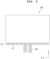
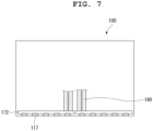
- FIG. 6 and FIG. 7 are diagrams illustrating a rear surface of a display panel according to an embodiment of the present disclosure.
- the display device includes a display module 10 and a wall mount assembly 50.
- the display module 10 includes a display panel and possibly a case member coupled to the display panel.
- the display module 10 may include a first long side LS1, a second long side LS2 opposite to the first long side LS1, a first short side SS1 adjacent to the first long side LS1 and the second long side LS2, and a second short side SS2 opposite to the first short side SS1.
- the first short side area SS1 may be referred to as a first side area
- the second short side area SS2 may be referred to as a second side area opposite to the first side area
- the first long side area LS1 may be referred to as a third side area adjacent to the first side area and the second side area and located between the first side area and the second side area
- the second long side area LS2 may be referred to as a fourth side area adjacent to the first side area and the second side area, located between the first side area and the second side area, and opposite to the third side area.
- first and second long sides LS1 and LS2 are illustrated and described as being longer than the first and second short sides SS1 and SS2 for convenience of description, the lengths of the first and second long sides LS1 and LS2 may be approximately equal to the lengths of the first and second short sides SS1 and SS2.
- a first direction DR1 may be is a direction parallel to the long sides LS1 and LS2 of the display module 10
- a second direction DR2 may be a direction parallel to the short sides SS1 and SS2 of the display module 10.
- the first direction DR1 may be parallel to a horizontal axis.
- the first direction DR1 may be referred to as a first horizontal axis.
- the second direction DR2 may be parallel to a vertical axis.
- the second direction DR2 may be referred to as a vertical axis.
- a third direction DR3 may be parallel to the horizontal axis.
- the third direction DR3 may be referred to as a second horizontal axis.
- a side on which the display module 10 displays an image may be referred to as a front side or a front surface.
- a side from which the image cannot be observed may be referred to as a rear side or a rear surface.
- the third direction DR3 may be a back-and-forth direction.
- a lateral side of the display module 10 means one of the right side and the left side of the display module 10.
- first long side LS1, the second long side LS2, the first short side SS1, and the second short side SS2 may be referred to as edges of the display module 10. Further, points where the first long side LS1, the second long side LS2, the first short side SS1, and the second short side SS2 meet may be referred to as corners.
- the point where the first long side LS1 and the first short side SS1 meet may be a first corner C1
- the point where the first long side LS1 and the second short side SS2 meet may be a second corner C2
- the point where the second short side SS2 and the second long side LS2 meet may be a third corner C3
- the point where the second long side LS2 and the first short side SS1 meet may be a fourth corner C4.
- a direction from the first short side SS1 to the second short side SS1 or a direction from the second short side SS2 to the first short side SS1 may be referred to as a left-right direction LR.
- a direction from the first long side LS1 to the second long side LS2 or a direction from the second long side LS2 to the first long side LS1 may be referred to as an up-down direction UD.
- the wall mount assembly 50 is fixed to a fixed object 1000 such as a wall. That is, the wall mount assembly 50 may be fixed to an arbitrary predetermined position such as a wall such that the movement thereof can be restricted.
- the wall mount assembly 50 may be fixed to an attachment surface of the fixed object 1000 through a fixing member such as a screw.
- the attachment surface may refer to one surface of the fixed object 1000 to which the wall mount assembly 50 is fixed.
- the wall mount assembly 50 may fix the display module 10 to the fixed object 1000.
- the wall mount assembly 50 may serve to change the position of the display module 10 in response to the position of a user according to user demand. That is, the wall mount assembly 50 may fix the display module 10 to the fixed object 1000 such that the position of the display module 10 can be changed within a preset range.
- the movement of the display module 10 and the wall mount assembly 50 may be caused by a physical external force directly provided by a user. For example, when the user applies a force to the display module 10 after gripping the display module 10, the position of the display module 10 may be changed within a range allowed by the wall mount assembly 50.
- the movement of the wall mount assembly 50 may be controlled through a control unit in response to a predetermined specific signal. That is, a state change of the wall mount assembly 50 may be controlled by a selected driving device, driving circuit, and the like.
- the wall mount assembly 50 may allow translational motion of the display module 10.
- the wall mount assembly 50 may separate the display module 10 forward by a predetermined distance from the fixed object 1000 or may allow the display module 10 to come close to or contact the fixed object 1000. That is, the wall mount assembly 50 may allow the display module 10 to be moved forward and backward within a preset range.
- the wall mount assembly 50 may allow a swivel motion of the display module 10.
- the wall mount assembly 50 may allow the other side of the display module 10 to move.
- the wall mount assembly 50 may allow the right side of the display module 10 to move forward or backward while movement of the left side of the display module 10 is limited to a preset position.
- the wall mount assembly 50 allows a tilting motion of the display module 10.
- the wall mount assembly 50 moves at least one side of the display module 10 up and down in an initial state (or a reference state) such that the display module 10 tilts in one direction from the initial state.
- the display device includes the display module 10 and the wall mount assembly 50.
- the display module 10 includes a display panel and possibly a case member.
- the display panel 100 is provided on the front side of the display device and can display images.
- the display panel 100 may output an image by dividing the image into a plurality of pixels and matching color, brightness, and saturation for each pixel.
- the display panel 100 may be divided into an active area in which an image is displayed and an inactive area in which an image is not displayed.
- the display panel 100 may include an organic display panel (OLED panel).
- OLED panel organic display panel
- the display panel 100 can spontaneously emit light.
- the display panel 100 may be very thin.
- the case member may include an inner plate 200, a module cover 300, a back cover 400, and a wall mount plate 600.
- the inner plate 200 may be located at the rear of the display panel 100.
- the inner plate 200 may be attached to the rear surface of the display panel 100.
- the inner plate 200 may be coupled to the rear surface of the display panel 100 through one or more adhesive members.
- the module cover 300 may be located at the rear of the inner plate 200.
- the module cover 300 may form an inner space in the front thereof.
- the display panel 100 and the inner plate 200 may be accommodated in the inner space provided in front of the module cover 300.
- the module cover 300 may cover at least parts of the sides of the inner plate 200 and the display panel 100.
- the inner space provided in front of the module cover 300 may be referred to as a front accommodating part.
- the module cover 300 may form an inner space at the rear thereof.
- Electronic components may be accommodated in the inner space provided at the rear of the module cover 300.
- the electronic components may include a timing controller board 501, a power supply 503, a main board 504, a speaker 505, and the like.
- the electronic components may be fixed to the rear of the module cover 300.
- the inner space provided at the rear of the module cover 300 may be referred to as a rear accommodating part.
- the electronic components may be seated in the rear accommodating part.
- the rear accommodating part may be divided into a plurality of parts to provide a plurality of spaces, the electronic components may be respectively accommodated in the divided spaces.
- the module cover 300 may be made of a polymer material.
- the module cover 300 may be formed of a plastic material. That is, the module cover 300 may be formed of a plastic-based material that can be molded.
- the module cover 300 may be formed of polycarbonate but is not limited thereto.
- the module cover 300 and the inner plate 200 may be fixed to each other through at least one fixing member.
- the fixing member may be a screw but is not limited thereto.
- the back cover 400 may be located at the rear of the module cover 300.
- the back cover 400 may cover at least a part of the rear surface of the module cover 300.
- the back cover 400 may be positioned to cover the rear accommodating part of the module cover 300.
- the back cover 400 may protect the electronic components accommodated in the rear accommodating part of the module cover 300.
- the back cover 400 may be made of a material different from that of the module cover 300.
- the back cover 400 may include a metal material.
- the back cover 400 may be formed through processing through a press process.
- the back cover 400 and the module cover 300 may be fixed to each other through at least one fixing member.
- the fixing member may be a screw.
- the fixing member may be a latch. As the back cover 400 and the module cover 300 are fastened using a plurality of latches, they may be free from space constraints with respect to surrounding members or parts. Accordingly, a degree of freedom in design can be improved.
- the rear surface of the back cover 400 may include a forming part 401.
- the forming part 401 may have a shape that is recessed toward the front from the rear surface of the back cover 400.
- the forming part 401 may be a part into which at least a part of the wall mount assembly 50 is inserted.
- the wall mount plate 600 may be positioned between the module cover 300 and the back cover 400.
- the wall mount plate 600 may be fixed to the module cover 300.
- the wall mount plate 600 may be fixed to the upper central portion of the module cover 300.
- the wall mount plate 600 may be positioned to overlap the forming part 401.
- the wall mount plate 600 may be a part to which the spacer 610 is fixed. Although not shown, a wall mount bracket for reinforcing the rigidity of the wall mount plate 600 may be further provided. However, in order to realize a slim display device, it may be desirable that the wall mount bracket be omitted.
- the spacer 610 may include at least a pair of a first spacer 610a and a second spacer 610b.
- the first spacer 610a and the second spacer 610b may be positioned at the rear of the back cover 400.
- the first spacer 610a and the second spacer 610b may be positioned at symmetrical positions with respect to a virtual axis crossing the center of the wall mount plate 600 in the vertical direction.
- the first spacer 610a and the second spacer 610b may be respectively located at symmetrical positions with respect to a virtual axis crossing the center of the display module 10 in the vertical direction.
- the first spacer 610a and the second spacer 610b may be fixed to the wall mount plate 600 through a first open hole 403a and a second open hole 403b that penetrate the back cover 400, respectively.
- a first nut 601a and a second nut 601b may be fixed to the wall mount plate 600, and a first bolt 610a1 and a second bolt 601b1 may be respectively fixed to the first spacer 610a and the second spacer 610b.
- the first bolt 610a1 may penetrate the first open hole 403a and be fixed to the first nut 601a
- the second bolt 610b1 may penetrate the second open hole 403b and be fixed to the second nut 601b.
- the wall mount assembly 50 may be located at the rear of the back cover 400.
- the wall mount assembly 50 may be movably fastened to at least a pair of the first spacer 610a and the second spacer 610b. The specific configuration of the wall mount assembly 50 will be described later.
- a member layer 117 may extend from one side of the display panel 100.
- the member layer 117 may have a shape extending from the second long side LS2 of the display panel 100.
- a plurality of member layers 117 may be provided.
- the member layer 117 may be electrically connected to the display panel 100.
- the member layer 117 may include at least one of a chip-on-film (COF), a chip-on-glass (COG), a flexible printed circuit board (FPCB), and a tape carrier package (TCP).
- COF chip-on-film
- COG chip-on-glass
- FPCB flexible printed circuit board
- TCP tape carrier package
- a source PCB 172 may have a shape extending from the member layer 117.
- the source PCB 172 may be electrically connected to the member layer 117.
- a plurality of source PCBs 172 may be provided.
- a cable 190 may have a shape extending from the source PCB 172.
- the cable 190 may be electrically connected to the source PCB 172.
- a plurality of cables 190 may be provided.
- Power and/or signals provided to the cable 190 may be delivered to the source PCB 172. Power and/or signals provided to the source PCB 172 may be distributed to the member layer 117. Power and/or signals distributed to the member layer 117 may be supplied to the display panel 110.
- the member layer 117 may be flexible.
- the member layer 117 may be bent toward the rear surface of the display panel 100.
- the member layer 117 may be positioned at the rear of the display panel 100.
- the source PCB 172 connected to the member layer 117 may be located at the rear of the display panel 100.
- the cable 190 connected to the source PCB 172 may be located at the rear of the display panel 100.
- the inner plate 200 may include a first slot 201.
- the first slot 201 may be formed penetrating the inner plate 200.
- the first slot 201 may be formed adjacent to the lower surface of the inner plate 200.
- the number of first slots 201 may correspond to the number of cables 190, and the cables 190 may extend toward the rear of the inner plate 200 through the first slots 201 corresponding thereto.
- the present disclosure is not limited thereto, and a plurality of cables 190 may penetrate one first slot 201.
- the module cover 300 may include a second slot 301.
- the second slot 301 may be formed penetrating the module cover 300.
- the second slot 301 may be formed adjacent to the lower surface of the module cover 300.
- the number of second slots 301 may be the same as the number of cables 190, and the cables 190 may extend toward the rear of the module cover 300 through the second slots 301 corresponding thereto.
- the present invention is not limited thereto, and a plurality of cables 190 may penetrate one second slot 301.
- the second slots 301 may overlap the first slots 201.
- the number of second slots 301 may be the same as the number of first slots 201.
- the cables 190 may penetrate the first slots 201 and the second slots 301 to be electrically connected to electronic components positioned at the rear of the module cover 300.
- the cables 190 may be electrically connected to the timing controller board 501 to receive power and/or signals.
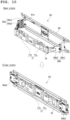
- FIG. 8 and FIG. 9 are perspective views showing a wall mount assembly according to an embodiment of the present disclosure.
- FIG. 10 is a diagram for describing an operating state (a folded state or an unfolded state) of a link according to an embodiment of the present disclosure.
- the wall mount assembly 50 includes a fixing part 60, a frame 70, and a link 80 that connects the fixing part 60 and the frame 70.
- the fixing part 60 is a part fixed to the fixed object 1000 such as a wall. That is, the fixing part 60 may be fixed to an arbitrary predetermined position such as a wall such that the movement thereof can be restricted.
- the wall mount assembly 50 may be fixed to the attachment surface of the fixed object 1000 through a fixing member such as a screw.
- the fixing part 60 may have a shape of a plurality of bars extending in one direction, and adjacent bars may be spaced apart from each other by a predetermined distance.
- the present disclosure is not limited thereto.
- the frame 70 is a part fastened to the spacer 610 fixed to the display module 10.
- the frame 70 may be in contact with the rear surface of the display module 10.
- the frame 70 may be provided to have a plate shape having a preset area and may support the display module 10 behind the display module 10. A detailed configuration of the frame 70 will be described later.
- the first link part 80a may include a (1-1)-th link 80a1 and a (1-2)-th link 80a2.
- the (1-1)-th link 80a1 and the (1-2)-th link 80a2 may be hinge-coupled. That is, one end of the (1-1)-th link 80a1 and one end of the (1-2)-th link 80a2 may be rotatably coupled to each other.
- one end of the (1-1)-th link 80a1 and one end of the (1-2)-th link 80a2 may be provided in a shape to match each other in male and female forms and may be coupled to each other.
- the (1-1)-th link 80a1 and the (1-2)-th link 80a2 may be rotatably provided with respect to each other based on a virtual axis extending in the vertical direction, and one surface of the (1-1)-th link 80a1 and one surface of the (1-2)-th link 80a2 may be located in contact with each other (e.g., in a folded state) or spaced apart from each other at a predetermined angle (e.g., in an unfolded state) in response to rotation.
- a friction member for providing a predetermined frictional force during rotation may be provided between fixing structures of one end of the (1-1)-th link 80a1 and one end of the (1-2)-th link 80a2.
- the (1-1)-th link 80a1 and the (1-2)-th link 80a2 do not rotate with respect to each other and may maintain a previous state as long as the user does not provide a force greater than or equal to a preset level.
- a first accommodating recess 81a in which the (1-2)-th link 80a2 can be accommodated may be provided on one surface of the (1-1)-th link 80a1. At least a part of the (1-2)-th link 80a2 may be accommodated in the first accommodating recess 81a of the (1-1)-th link 80a1. Accordingly, the overall thickness of the wall mount assembly 50 can be reduced in a state in which the (1-1)-th link 80a1 and the (1-2)-th link 80a2 are folded.
- a friction member for providing a predetermined frictional force during rotation may be provided between fixing structures of the other end of the (1-1)-th link 80a1 and one end of the fixing part 60. Due to the friction member, the (1-1)-th link 80a1 may maintain the previous state thereof without rotating with respect to the fixing part 60 as long as the user does not provide a force equal to or greater than a preset level.
- the (1-2)-th link 80a2 may be hinge-connected to one end of the frame 70. That is, the other end of the (1-2)-th link 80a2 may be rotatably coupled to one end of the frame 70.
- the other end of the (1-2)-th link 80a2 and one end of the frame 70 may be provided in a shape to match each other in male and female forms and may be coupled to each other.
- the (1-2)-th link 80a2 may be rotatably provided with respect to the frame 70 based on a virtual axis extending in the vertical direction and may be positioned in parallel to the frame 70 or may be positioned to have a predetermined angle with respect to the frame 70 in response to rotation.
- a friction member for providing a predetermined frictional force during rotation may be provided between fixing structures of the other end of the (1-2)-th link 80a2 and one end of the frame 70. Due to the friction member, the (1-2)-th link 80a2 may maintain the previous state thereof without rotating with respect to the frame 70 as long as the user does not provide a force equal to or greater than a preset level.
- the (2-1)-th link 80b1 and the (2-2)-th link 80b2 may be hinge-coupled. That is, one end of the (2-1)-th link 80b1 and one end of the (2-2)-th link 80b2 may be rotatably coupled to each other.
- one end of the (2-1)-th link 80b1 and one end of the (2-2)-th link 80b2 may be provided in a shape to match each other in male and female forms and may be coupled to each other.
- the (2-1)-th link 80b1 and the (2-2)-th link 80b2 may be rotatably provided with respect to each other based on a virtual axis extending in the vertical direction, and one surface of the (2-1)-th link 80b1 and one surface of the (2-2)-th link 80b2 may be located in contact with each other (e.g., in a folded state) or spaced apart from each other at a predetermined angle (e.g., in an unfolded state) in response to rotation.
- a friction member for providing a predetermined frictional force during rotation may be provided between fixing structures of one end of the (2-1)-th link 80b1 and one end of the (2-2)-th link 80b2.
- the (2-1)-th link 80b1 and the (2-2)-th link 80b2 do not rotate with respect to each other and may maintain a previous state as long as the user does not provide a force equal to or greater than a preset level.
- a friction member for providing a predetermined frictional force during rotation may be provided between fixing structures of the other end of the (2-1)-th link 80b1 and the other end of the fixing part 60. Due to the friction member, the (2-1)-th link 80b1 may maintain the previous state thereof without rotating with respect to the fixing part 60 as long as the user does not provide a force equal to or greater than a preset level.
- the (2-2)-th link 80b2 may be hinge-connected to the other end of the frame 70. That is, the other end of the (2-2)-th link 80b2 may be rotatably coupled to the other end of the frame 70.
- the other end of the (2-2)-th link 80b2 and the other end of the frame 70 may be provided in a shape to match each other in male and female forms and may be coupled to each other.
- the (2-2)-th link 80b2 may be rotatably provided with respect to the frame 70 based on a virtual axis extending in the vertical direction and may be positioned in parallel to the frame 70 or may be positioned to have a predetermined angle with respect to the frame 70 in response to rotation.
- a friction member for providing a predetermined frictional force during rotation may be provided between fixing structures of the other end of the (2-2)-th link 80b2 and the other end of the frame 70. Due to the friction member, the (2-2)-th link 80b2 may maintain the previous state thereof without rotating with respect to the frame 70 as long as the user does not provide a force equal to or greater than a preset level.
- the frame 70 fixed to the display module 10 can allow the translational motion and swivel motion of the display module 10 as described above according to the structures of the first link part 80a and the second link part 80b.
- FIG. 11 is a diagram for describing the structure of the frame and the relationship between the frame and the spacer according to an embodiment of the present disclosure.
- the display device includes spacers 610 and tilting holes 71 provided to allow a tilting motion of the display module 10.
- the display module 10 includes at least a pair of a first spacer 610a and a second spacer 610b.
- the first spacer 610a and the second spacer 610b are positioned at the rear of the display module 10 and may be disposed at an upper central portion.
- the first spacer 610a and the second spacer 610b may be respectively positioned on one side and the other side to be symmetrical with respect to a virtual axis crossing the center of the display module 10 in the vertical direction.
- the frame 70 of the wall mount assembly 50 includes at least a pair of a first tilting hole 71a and a second tilting hole 71b.
- the first tilting hole 71a is formed at a position corresponding to the first spacer 610a in the frame 70 and the second tilting hole 71b is formed at a position corresponding to the second space 610b in the frame 70.
- the first tilting hole 71a and the second tilting hole 71b may be respectively located on one side and the other side to be symmetrical with respect to a virtual axis crossing the center of the frame part 70 in the vertical direction.
- the first spacer 610a and the second spacer 610b fixed to the display module 10 are fastened to the first tilting hole 71a and the second tilting hole 71b, respectively.
- the first tilting hole 71a and the second tilting hole 71b restrict movement of the first spacer 610a and the second spacer 610b fixed to the display module 10. This means that movement of the display module 10 in at least one direction may be restricted in response to the shape of the tilting hole 71.
- the first tilting hole 71a and the second tilting hole 71b guide moving paths of the first spacer 610a and the second spacer 610b fixed to the display module 10. This means that the display module 10 is tilted or shifted in a preset direction in response to the shape of the tilting hole 71.
- FIG. 12 is a diagram for describing the shape of the spacer according to an embodiment of the present disclosure.
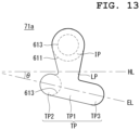
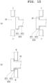
- FIG. 13 to FIG. 15 are diagrams for describing the structures of the spacer and the tilting hole according to an embodiment of the present disclosure.
- the spacer 610 includes a spacer head 611 and a spacer neck 613.
- the spacer head 611 and the spacer neck 613 may have different cross-sectional areas in a plan view.
- the spacer head 611 and the spacer neck 613 may have cylindrical shapes having different diameters. That is, the spacer head 611 has a cylindrical shape having a first diameter FRD, and the spacer neck 613 may have a cylindrical shape extending from the spacer head 611 and having a second diameter SRD less than the first diameter FRD. Since the spacer 610 includes the spacer head 611 and the spacer neck 613 having different diameters, the spacer 610 may be easily fastened to at least one side of the tilting hole 71 which will be described later.
- the inlet portion IP may be a portion into/from which the spacer 610 is inserted/released. That is, the inlet portion IP may have a sufficient hole area through which both the spacer head 611 and the spacer neck 613 can be inserted into the inlet portion IP and released therefrom. In other words, the inlet portion IP may have a larger hole area than the first diameter FRD of the spacer head 611. In other words, in the inlet portion IP, forward and backward movements of the spacer head 611 and the spacer neck 613 are not constrained.
- the inlet portion IP has a substantially circular shape in the figure, the present disclosure is not limited thereto.
- the inlet portion IP may have various planar figure shapes such as a rectangle, a square, and an oval.
- the guide portion TP may include a seating part TP1 and first and second extension parts TP2 and TP3 extending from the seating part TP1 in one direction.
- the first extension part TP2 and the second extension part TP3 may extend in a reverse direction with respect to the seating part TP1.
- An extension line EL in the extension direction of the first and second extension parts TP2 and TP3 and a horizontal line HL in the horizontal direction intersect each other, and the angle ⁇ therebetween is a tilting angle (dutch angle).
- the tilting angle means an inclined angle that is not vertical or horizontal. It may be desirable that an acute angle between the extension line EL and the horizontal line HL be 5° ⁇ 30°.
- the guide portion TP may be a part to which the spacer 610 is fixed in the tilting hole 71.
- the seating part TP1 may be a part where the spacer 610 moving along the shape of the tilting hole 71 in response to the movement of the display module 10 is first seated in the guide portion TP.
- the display module 10 When a predetermined external force is provided, the display module 10 may be tilted in one direction and the spacer 610 may move along the shape of the guide portion TP in response thereto. The moving direction of the spacer 610 may be guided along the shape of the guide portion TP.
- the guide portion TP has a hole area through which the spacer head 611 cannot be inserted into the guide portion TP and released therefrom. That is, the guide portion TP may have a smaller hole area than the first diameter FRD of the spacer head 611. Accordingly, forward movement of the spacer head 611 inserted toward the rear of the frame 70 through the inlet portion IP is restricted by the guide portion TP. Accordingly, the spacer 610 is not separated from the guide portion TP.
- the guide portion TP has a hole area through which the spacer neck 613 can pass. That is, the guide portion TP may have a larger hole area than the second diameter SRD of the spacer neck 613.
- the tilting hole 71 may further include a link portion LP connecting the inlet portion IP and the guide portion TP.
- the link portion LP may serve as a moving path of the spacer 610 moving between the inlet portion IP and the guide portion TP.
- the link portion LP may serve a moving path through which the spacer 610 inserted through the inlet portion IP moves to the guide portion TP such that the spacer 610 can be seated in the tilting hole 71.
- the link portion LP may serve as a moving path through which the spacer 610 seated on the guide portion TP moves to the inlet portion IP such that the spacer 610 can be separated from the tilting hole 71.
- the tilting hole 71 includes the link portion LP, a sufficient moving path of the spacer 610 may be secured. Accordingly, it is possible to prevent the spacer 610 seated on the guide portion TP from moving to the inlet portion IP by an unintentionally provided external force and thus being separated from the tilting hole 71.
- the link portion LP has a hole area through which the spacer head 611 cannot be inserted into the link portion LP and released therefrom. That is, the link portion LP may have a smaller hole area than the first diameter FRD of the spacer head 611. Accordingly, forward movement of the spacer head 611 inserted toward the rear of the frame part 70 through the inlet portion IP is restricted by the link portion LP. Accordingly, the spacer 610 is not separated from the link portion LP.
- the link portion LP may have a hole area through which the spacer neck 613 can pass. That is, the guide portion TP may have a larger hole area than the second diameter SRD of the spacer neck 613.
- the hole area of the link portion LP may be different from the hole area of the guide portion TP
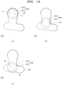
- FIG. 16 to FIG. 18 are diagrams for describing the positional relationship and shape of a pair of spacers according to the present disclosure.
- the display module 10 includes at least a pair of the first spacer 610a and the second spacer 610b. At least a pair of the first tilting hole 71a and the second tilting hole 71b are provided in the frame 70 of the wall mount assembly 50.
- the first spacer 610a is provided at a position corresponding to the first tilting hole 71a and movably inserted into the first tilting hole 71a.
- the second spacer 610b is provided at a position corresponding to the second tilting hole 71b and movably inserted into the second tilting hole 71b.
- the display module 10 fastened to the frame 70 of the wall mount assembly 50 may be tilted in a preset direction. However, the current state (or fixed state) of the display module 10 coupled to the wall mount assembly 50 may be maintained until a predetermined external force is provided.
- the preset direction may be determined according to the positions and shapes of the first tilting hole 71a and the second tilting hole 71b. In particular, the preset direction may be determined according to the positions and shapes of the guide portion TP of the first tilting hole 71a (hereinafter referred to as a "first guide portion TPa") and the guide portion TP of the second tilting hole 71b (hereinafter referred to as a "second guide portion TPb").
- the first guide portion TPa and the second guide portion TPb may be positioned on the line of a virtual arc ARC.
- the virtual arc ARC may mean a virtual curve connecting the center of the first guide portion TPa and the center of the second guide portion TPb.
- the virtual arc ARC may have a shape that is convexly curved downward ( FIG. 16(a) ) or convexly curved upward ( FIG. 16(b) ).
- the center of the first guide portion TPa and the center of the second guide portion TPb may be located on the line of the virtual arc ARC in areas corresponding to the left and right sides of the frame 70, respectively.
- the virtual arc ARC may be an arc that is a part of the circumference of a circle having a virtual center point.
- the virtual center point may be located on a reference line RL crossing the center of the frame 70 in the vertical direction.
- the curvature of the virtual arc ARC may vary depending on the position of the center point on the reference line RL.
- the center of the first guide portion TPa positioned on the line of the virtual arc ARC may correspond to the center of the first spacer 610a fixed to the display module 10.
- the center of the first guide portion TPa positioned on the line of the virtual arc ARC may correspond to the center of the spacer neck 613 of the first spacer 610a.
- the center of the first spacer 610a may be the center of a circle.
- the center of the second guide portion TPb positioned on the line of the virtual arc ARC may correspond to the center of the second spacer 610b fixed to the display module 10.
- the center of the second guide portion TPb positioned on the line of the virtual arc ARC may correspond to the center of the spacer neck 613 of the second spacer 610b.
- the center of the second spacer 610b may be the center of a circle.
- the extension direction of the first guide portion TPa may be a direction in which the tangent line TL of the virtual arc ARC passing through the centers of the first and second guide portions TPa and TPb extends.
- the extension direction of the second guide portion TPb forming a pair with the first guide portion TPa may be a direction in which the tangent line TL of the virtual arc ARC passing through the centers of the first and second guide portions TPa and TPb extends.
- the extension direction of the first guide portion TPa may be a direction in which the virtual arc ARC passing through the centers of the first and second guide portions TPa and TPb extends.
- the extension direction of the second guide portion TPb forming a pair with the first guide portion TPa may be a direction in which the virtual arc ARC passing through the centers of the first and second guide portions TPa and TPb extends.
- the first guide portion TPa and the second guide portion TPb have a curved shape.
- the first tilting hole 71a and the second tilting hole 71b may have symmetrical shapes.
- the first tilting hole 71a and the second tilting hole 71b may be respectively located in areas corresponding to one side and the other side of the frame 70 such that they are line-symmetrical with respect to a virtual reference line RL.
- the virtual reference line RL may be a virtual straight line crossing the center of the frame 70 in the vertical direction.
- a first angle ⁇ 1 formed between a first extension line EL1 extending in the extension direction of the first guide portion TPa and a horizontal line HL extending in the horizontal direction may be the same as a second angle ⁇ 2 formed between a second extension line EL2 extending in the extension direction of the second guide portion TPb and the horizontal line HL extending in the horizontal direction.
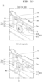
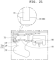
- FIG. 19 to FIG. 21 are diagrams for describing a locking part according to an embodiment of the present disclosure.
- the frame 70 according to the claimed invention includes a locking part 90.
- the locking part 90 is fastened to the frame 70 and serves to selectively limit the moving path of the spacer 610 inserted into the tilting hole 71. That is, the locking part 90 may serve to selectively open and close the moving path of the spacer 610 inserted into the tilting hole 71 according to user demand.
- the locking part 90 is hinged to the frame 70 and may be provided rotatably with respect to the frame 70.
- the locking part 90 may be located at the rear of the frame 70. At least a portion of the locking part 90 may be positioned to overlap the tilting hole 71.
- At least a portion of the locking part 90 may be positioned to correspond to the area between the inlet portion IP and the guide portion TP of the tilting hole 71 and may selectively restrict a moving path of the spacer 610 moving between the inlet portion IP and the guide portion TP.
- at least a portion of the locking part 90 may be positioned to correspond to the link portion LP of the tilting hole 71 and may selectively restrict the moving path of the spacer 610 moving from the guide portion TP to the inlet portion IP, but the present disclosure is not limited thereto.
- At least a portion of the locking part 90 blocking the moving path of the spacer 610 may be referred to as a blocking part 91.
- the locking part 90 may have a rod shape elongated to have an approximately U-shape.
- the locking part 90 may have an open loop shape in which a part is opened.
- the locking part 90 may include at least one bent part or bending part but is not limited thereto.
- the frame 70 may include a first through-hole 75a and a second through-hole 75b that penetrate in the vertical direction.
- One end of the locking part 90 may be rotatably coupled to the first through-hole 75a with respect to a virtual axis extending in the vertical direction, and the other end of the locking part 90 may be rotatably coupled to the second through-hole 75b with respect to the virtual axis extending in the vertical direction.
- the through-hole 75 may be formed in a protrusion 72 protruding backward from the frame 70.
- At least a portion of the locking part 90 may extend to cross the inlet portion IP to block the movement of the spacer 610 inserted into the guide portion TP to the inlet portion IP.
- the locking mode it is possible to prevent the spacer 610 inserted into the guide portion TP from being unintentionally moving to the inlet portion IP and being released from the tilting hole 71.
- At least a portion of the locking part 90 may be spaced apart from the frame 70 backward such that the movement of the spacer 610 inserted into the guide portion TP is not blocked. That is, since the moving path of the spacer 610 is not limited by the locking part 90 in the unlocking mode, the spacer 610 inserted into the guide portion TP can move to the inlet portion IP and be released from the tilting hole 71.
- the frame 70 may further include a stopper 73 for limiting the movement of the locking part 90 in the locking mode.
- the stopper 73 may have a shape protruding backward from the frame 70.
- the stopper 73 may be positioned around the tilting hole 71.
- the stopper 73 may be positioned around the inlet portion IP.
- the stopper 73 may extend from the periphery of the inlet portion IP along the shape of the inlet portion IP but is not limited thereto.
- the lower surface 73a of the stopper 73 may be positioned to contact the blocking part 91. That is, in the locking mode, the blocking part 91 of the locking part 90 may be in contact with the lower surface 73a of the stopper 73 and the upward movement thereof may be restricted by the stopper 73. Accordingly, the movement of the spacer 610 can be restricted by the stopper 73 more effectively. That is, it is possible to effectively block the movement of the spacer 610 in the locking mode by further including the stopper 73.
- At least a portion of the locking part 90 may be positioned to surround the outer periphery of the stopper 73.
- the lower surface 73a of the stopper 73 may further include a trench 74.
- the trench 74 may have a shape partially recessed from the lower surface 73a of the stopper 73 upward.
- the lower surface 73a of the stopper 73 on which the trench 74 is formed may have an inclined shape ((a) of FIG. 20 ) or a rounded shape ((b) of FIG. 20 ), but is not limited thereto.
- the blocking part 91 of the locking part 90 may be positioned to overlap one end of the stopper 73 corresponding to the lower surface 73a of the stopper 73. Accordingly, in the locking mode, at least a portion of the blocking part 91 of the locking part 90 can be accommodated in the internal space of the trench 74 and the backward movement thereof can be limited. That is, in the locking mode, the blocking part 91 of the locking part 90 may maintain a state in which it is accommodated in the internal space of the trench 74 unless an external force equal to or greater than a predetermined value is provided. Accordingly, it is possible to prevent the lock part 90 from being unintentionally released in the locking mode.
- the user can release the blocking part 91 of the locking part 90 from the trench 74 by providing a predetermined force to the locking part 90.
- the user since the user can recognize whether the locking part 90 is seated in the trench 74 or released from the trench 74 by a click sound or fingertip sense and thus can easily ascertain locking or unlocking.
- FIG. 22 and FIG. 23 are diagrams for describing an auxiliary locking part according to an embodiment of the present disclosure.
- the wall mount assembly may further include an auxiliary locking part 95.
- the auxiliary locking part 95 is fixed to the fixing part 60 and may serve to selectively limit the movement of the frame 70.
- the auxiliary locking part 95 may be an elastic member having predetermined elasticity.
- the auxiliary locking part 95 may be a leaf spring, but is not limited thereto.
- auxiliary locking part 95 may be fixed to the fixing part 60.
- the other end of the auxiliary locking part 95 may extend downward from one end of the auxiliary locking part 95 and may be positioned to overlap at least a part of the frame 70 in the back-and-forth direction.
- the other end of the auxiliary locking part 95 may be positioned in front of the frame 70 such that the forward movement of the frame 70 is restricted.
- the state in which the display module 10 is in a position close to the fixed object 1000 may mean a state in which one surface of the (1-1)-th link 80a1 and the (1-2)-th link 80a2 constituting the first link part 80a are in contact with each other, one surface of the (2-1)-th link 80b1 and one surface of the (2-2)-th link 80b2 constituting the second link part 80b are in contact with each other.
- the state in which the display module 10 is in a position close to the fixed object 1000 may mean a state in which the translational motion and the swivel motion of the display module 10 are restricted.
- the other end of the auxiliary locking part 95 may be located at the rear of the frame 70 such that the forward movement of the frame 70 is not restricted.
- the state in which the display module 10 is spaced apart from the fixed object 1000 may mean a state in which one surface of the (1-1)-th link 80a1 and the (1-2)-th link 80a2 constituting the first link part 80a are spaced apart by a predetermined angle, and one surface of the (2-1)-th link 80b1 and one surface of the (2-2)-th link 80b2 constituting the second link portion 80b are spaced apart by a predetermined angle.
- the state in which the display module 10 is spaced apart from the fixed object 1000 may mean a state in which the translational motion and the swivel motion of the display module 10 are permitted.
Landscapes
- Engineering & Computer Science (AREA)
- General Engineering & Computer Science (AREA)
- Mechanical Engineering (AREA)
- Physics & Mathematics (AREA)
- Nonlinear Science (AREA)
- General Physics & Mathematics (AREA)
- Theoretical Computer Science (AREA)
- Crystallography & Structural Chemistry (AREA)
- Chemical & Material Sciences (AREA)
- Optics & Photonics (AREA)
- Mathematical Physics (AREA)
- Computer Hardware Design (AREA)
- Human Computer Interaction (AREA)
- Devices For Indicating Variable Information By Combining Individual Elements (AREA)
Claims (15)
- Anzeigevorrichtung, umfassend:ein Anzeigemodul (10) mit einem Anzeigefeld (100);mindestens ein Paar von ersten und zweiten Abstandshaltern (610a, 610b), die an der Rückseite des Anzeigemoduls (10) angeordnet und an dem Anzeigemodul (10) befestigt sind; undeine Wandbefestigungsbaugruppe (50), die an der Rückseite einer hinteren Abdeckung (400) angeordnet ist und an den ersten und zweiten Abstandshaltern (610a, 610b) befestigt ist, während sie Kippbewegungen des Anzeigemoduls (10) und der ersten und zweiten Abstandshalter (610a, 610b) ermöglicht,wobei sich bei einer Kippbewegung eine seitliche Seite des Anzeigemoduls von einem Ausgangszustand nach oben oder unten bewegt, während sich die gegenüberliegende seitliche Seite des Anzeigemoduls in die entgegengesetzte Richtung bewegt,wobei die Wandbefestigungsbaugruppe (50) umfasst:ein Befestigungsteil (60), das an einem festen Gegenstand (1000) befestigt ist;einen Rahmen (70) mit einem Paar von ersten und zweiten Kipplöchern (71a, 71b), in die die ersten und zweiten Abstandshalter (610a, 610b) jeweils eingesetzt sind, und die Bewegungswege der ersten und zweiten Abstandshalter (610a, 610b) so führt, dass das Anzeigemodul (10) in Abhängigkeit von der Form der Kipplöcher (71a, 71b) gekippt werden kann, undein Verriegelungsteil (90) zum selektiven Einschränken der Bewegungswege der ersten und zweiten Abstandshalter (610a, 610b), die in das erste und zweite Kipploch (71a, 71b) eingesetzt sind; undein Verbindungsglied (80), das das Befestigungsteil (60) und den Rahmen (70) miteinander verbindet.
- Anzeigevorrichtung nach Anspruch 1, wobei jedes der ersten und zweiten Kipplöcher (71a, 71b) umfasst:einen Einlassabschnitt (IP), der vorgesehen ist, um zu ermöglichen, dass die ersten und zweiten Abstandshalter (610a, 610b) in den Einlassabschnitt (IP) eingeführt und aus diesem freigegeben werden können; undeinen Führungsabschnitt (TP), der unter dem Einlassabschnitt (IP) angeordnet ist, in dem die ersten und zweiten Abstandshalter (610a, 610b), die durch den Einlassabschnitt (IP) eingeführt werden, sitzen, undwobei das Verriegelungsteil (90) ein Blockierteil (91) umfasst, das drehbar am Rahmen (70) befestigt und zwischen dem Einlassabschnitt (IP) und dem Führungsabschnitt (TP) angeordnet ist.
- Anzeigevorrichtung nach Anspruch 2, wobei jedes der ersten und zweiten Kipplöcher (71a, 71b) einen Verbindungsabschnitt (LP) aufweist, der den Einlassabschnitt (IP) und den Führungsabschnitt (TP) verbindet, und der Blockierteil (91) so angeordnet ist, dass er dem Verbindungsabschnitt (LP) entspricht.
- Anzeigevorrichtung nach einem der vorhergehenden Ansprüche, wobei ein Ende und ein anderes Ende des Verriegelungsteils (90) drehbar an dem Rahmen (70) befestigt sind.
- Anzeigevorrichtung nach Anspruch 2, wobei jeder der ersten und zweiten Abstandshalter (610a, 610b) umfasst:einem Abstandshalterkopf (611) mit einem ersten Durchmesser (FRD); undeinen Abstandshalterhals (613), der sich von dem Abstandshalterkopf (611) aus erstreckt und einen zweiten Durchmesser (SRD) aufweist, der kleiner ist als der erste Durchmesser (FRD),wobei der Einlassabschnitt (IP) eine Lochfläche aufweist, die größer ist als der erste Durchmesser (FRD), undwobei der Führungsabschnitt (TP) eine Lochfläche aufweist, die kleiner als der erste Durchmesser (FRD) und größer als der zweite Durchmesser (SRD) ist.
- Anzeigevorrichtung nach Anspruch 5, wobei der Führungsabschnitt (TP) umfasst:einem Sitzteil (TP1); underste und zweite Verlängerungsteile (TP2, TP3), die sich von dem Sitzteil (TP1) in eine Richtung erstrecken,wobei sich der erste und der zweite Verlängerungsteil (TP2, TP3) in umgekehrter Richtung von dem Sitzteil (TP1) aus erstrecken.
- Anzeigevorrichtung nach Anspruch 6, wobei eine Verlängerungslinie (EL), die sich in der Verlängerungsrichtung des Führungsabschnitts (TP) erstreckt, und eine horizontale Linie (HL), die sich in einer horizontalen Richtung erstreckt, einander schneiden, und ein Winkel (θ), der durch die Verlängerungslinie (EL) und die horizontale Linie (HL) gebildet wird, ein Neigungswinkel ist.
- Anzeigevorrichtung nach Anspruch 6, wobei sich die Führungsabschnitte (TP) der ersten und zweiten Kipplöcher (71a, 71b) in einer geradlinigen Form in einer Tangentenrichtung eines virtuellen Bogens (ARC) erstrecken, der durch die Mittelpunkte der Führungsabschnitte (TP) der ersten und zweiten Kipplöcher (71a, 71b) verläuft, oder sich in einer gekrümmten Form in einer Verlängerungsrichtung des virtuellen Bogens (ARC) erstrecken.
- Anzeigevorrichtung nach Anspruch 8, wobei der virtuelle Bogen (ARC) ein Teil des Umfangs eines Kreises mit einem virtuellen Mittelpunkt ist,wobei der virtuelle Bogen (ARC) konvex nach oben oder konvex nach unten gekrümmt ist, undwobei der virtuelle Mittelpunkt auf einer Referenzlinie (RL) positioniert ist, die den Mittelpunkt des Rahmens in vertikaler Richtung kreuzt.
- Anzeigevorrichtung nach einem der vorhergehenden Ansprüche, wobei das erste und das zweite Kipploch (71a, 71b) symmetrisch in Bezug auf eine Referenzlinie (RL) sind, die die Mitte des Rahmens (70) in vertikaler Richtung kreuzt.
- Anzeigevorrichtung nach einem der vorhergehenden Ansprüche, die ferner ein Hilfsverriegelungsteil (95) umfasst, das mit einem Ende an dem Befestigungsteil (60) befestigt ist und eine vorbestimmte Elastizität aufweist,
wobei sich das andere Ende des Hilfsverriegelungsteils (95) von einem Ende des Hilfsverriegelungsteils (95) nach unten erstreckt und so angeordnet ist, dass es zumindest einen Teil des Rahmens (70) in einer Hin- und Herrichtung überlappt. - Anzeigevorrichtung nach einem der vorhergehenden Ansprüche, wobei das Anzeigemodul (10) umfasst:eine Modulabdeckung (300), die auf der Rückseite des Anzeigefelds (100) angeordnet ist;die hintere Abdeckung (400), die an der Rückseite der Modulabdeckung (300) angeordnet ist und erste und zweite offene Löcher (403a, 403b) aufweist, die so angeordnet sind, dass sie den ersten und zweiten Abstandshaltern (610a, 610b) entsprechen; undeine Wandmontageplatte (600), die zwischen der Modulabdeckung (300) und der hinteren Abdeckung (400) angeordnet und an der Modulabdeckung (300) befestigt ist,wobei der erste und der zweite Abstandshalter (610a, 610b) an der Wandmontageplatte (600) durch das erste bzw. zweite offene Loch (403a, 403b) an der Rückseite der hinteren Abdeckung (400) befestigt sind.
- Anzeigevorrichtung nach Anspruch 12, wobei die hintere Abdeckung (400) ein Formteil (401) umfasst, das die Wandmontageplatte (600) überlappt, und mindestens ein Teil der Wandmontageanordnung (50) in das Formteil (401) eingesetzt ist.
- Anzeigevorrichtung nach einem der vorhergehenden Ansprüche, wobei das Verbindungsglied (80) ein erstes Verbindungsglied (80a1) und ein zweites Verbindungsglied (80a2) umfasst, die drehbar miteinander verbunden sind, basierend auf einer virtuellen ersten Achse, die sich in der vertikalen Richtung erstreckt,
wobei ein Ende des ersten Glieds (80a1) drehbar mit dem Befestigungsteil (60) auf der Grundlage einer virtuellen zweiten Achse gekoppelt ist, die sich in der vertikalen Richtung erstreckt, und ein Ende des zweiten Glieds (80a2) drehbar mit dem Rahmen (70) auf der Grundlage einer virtuellen dritten Achse gekoppelt ist, die sich in der vertikalen Richtung erstreckt. - Anzeigevorrichtung nach Anspruch 14, wobei das erste Glied (80a1) eine Aufnahmeaussparung (81a) aufweist, die in der Lage ist, zumindest einen Teil des zweiten Glieds (80a2) aufzunehmen.
Applications Claiming Priority (2)
| Application Number | Priority Date | Filing Date | Title |
|---|---|---|---|
| KR1020190123636A KR102805858B1 (ko) | 2019-10-07 | 2019-10-07 | 디스플레이 장치 |
| PCT/KR2019/014470 WO2021071009A1 (ko) | 2019-10-07 | 2019-10-30 | 디스플레이 장치 |
Publications (3)
| Publication Number | Publication Date |
|---|---|
| EP4043778A1 EP4043778A1 (de) | 2022-08-17 |
| EP4043778A4 EP4043778A4 (de) | 2023-10-04 |
| EP4043778B1 true EP4043778B1 (de) | 2024-12-25 |
Family
ID=75438259
Family Applications (1)
| Application Number | Title | Priority Date | Filing Date |
|---|---|---|---|
| EP19948222.5A Active EP4043778B1 (de) | 2019-10-07 | 2019-10-30 | Anzeigevorrichtung |
Country Status (4)
| Country | Link |
|---|---|
| US (2) | US12019469B2 (de) |
| EP (1) | EP4043778B1 (de) |
| KR (1) | KR102805858B1 (de) |
| WO (1) | WO2021071009A1 (de) |
Families Citing this family (2)
| Publication number | Priority date | Publication date | Assignee | Title |
|---|---|---|---|---|
| KR102805858B1 (ko) * | 2019-10-07 | 2025-05-12 | 엘지전자 주식회사 | 디스플레이 장치 |
| EP4299967A4 (de) * | 2021-07-21 | 2025-02-12 | LG Electronics Inc. | Anzeigevorrichtung |
Family Cites Families (15)
| Publication number | Priority date | Publication date | Assignee | Title |
|---|---|---|---|---|
| KR100867108B1 (ko) * | 2002-09-19 | 2008-11-06 | 삼성전자주식회사 | 디스플레이 설치장치 및 설치장치용 지그 |
| US20040232298A1 (en) * | 2003-04-11 | 2004-11-25 | Jeff Bremmon | Flat panel display mounting system |
| KR100968455B1 (ko) | 2004-01-09 | 2010-07-07 | 삼성전자주식회사 | 디스플레이장치 |
| KR101339055B1 (ko) * | 2006-03-27 | 2014-01-02 | 사우스코 인코포레이티드 | 디스플레이 마운팅 장치 |
| KR20090040752A (ko) * | 2007-10-22 | 2009-04-27 | 삼성전자주식회사 | 평판 패널 디스플레이장치의 벽걸이용 지지장치 |
| JP5303739B2 (ja) * | 2008-07-28 | 2013-10-02 | ティーピー ビジョン ホールディング ビー ヴィ | パネルディスプレイ懸架システム及びパネルディスプレイ懸架システムを備えたパネルディスプレイ |
| KR100962008B1 (ko) * | 2009-04-21 | 2010-06-08 | 동오정밀 주식회사 | 평면 티비용 벽걸이 거치대 |
| WO2011088622A1 (en) | 2010-01-22 | 2011-07-28 | Ningbo Cinemount Design And Manufacturing Co., Ltd. | A tiltable flat panel display mount |
| KR101550598B1 (ko) | 2011-07-29 | 2015-09-18 | 현대자동차 주식회사 | 자동차용 스태빌라이저 바의 마운트 부시 |
| KR101868847B1 (ko) * | 2011-12-30 | 2018-06-21 | 삼성전자주식회사 | 디스플레이장치용 지지장치 |
| KR102560611B1 (ko) * | 2016-08-25 | 2023-07-27 | 엘지전자 주식회사 | 디스플레이 디바이스 |
| KR101949477B1 (ko) | 2017-11-10 | 2019-02-18 | (주)세아메카닉스 | 평면 디스플레이용 벽걸이 장치 |
| DE102018101210B4 (de) * | 2018-01-19 | 2019-08-22 | Fujitsu Client Computing Limited | Wandbefestigung für eine elektronische Anzeige, Computeranordnung und Verfahren zur Montage einer elektronischen Anzeige und eines Computersystems an einer Wand |
| KR102805858B1 (ko) * | 2019-10-07 | 2025-05-12 | 엘지전자 주식회사 | 디스플레이 장치 |
| EP4092313A4 (de) * | 2020-01-17 | 2023-10-18 | LG Electronics Inc. | Anzeigevorrichtung |
-
2019
- 2019-10-07 KR KR1020190123636A patent/KR102805858B1/ko active Active
- 2019-10-30 US US17/763,312 patent/US12019469B2/en active Active
- 2019-10-30 EP EP19948222.5A patent/EP4043778B1/de active Active
- 2019-10-30 WO PCT/KR2019/014470 patent/WO2021071009A1/ko not_active Ceased
-
2024
- 2024-05-23 US US18/672,780 patent/US20240310872A1/en active Pending
Also Published As
| Publication number | Publication date |
|---|---|
| EP4043778A4 (de) | 2023-10-04 |
| WO2021071009A1 (ko) | 2021-04-15 |
| US20240310872A1 (en) | 2024-09-19 |
| US20220374042A1 (en) | 2022-11-24 |
| KR102805858B1 (ko) | 2025-05-12 |
| KR20210041230A (ko) | 2021-04-15 |
| US12019469B2 (en) | 2024-06-25 |
| EP4043778A1 (de) | 2022-08-17 |
Similar Documents
| Publication | Publication Date | Title |
|---|---|---|
| US20240310872A1 (en) | Display device | |
| US9608231B2 (en) | Display apparatus | |
| US10476011B2 (en) | Display device | |
| KR102237598B1 (ko) | 디스플레이 장치 | |
| EP3179281A1 (de) | Anzeigevorrichtung | |
| US20200357311A1 (en) | Display apparatus and hinge assembly of display module | |
| EP3136714B1 (de) | Anzeigevorrichtung | |
| EP4425032B1 (de) | Anzeigevorrichtung | |
| US9541779B2 (en) | Display device including a curvature maintaining bar | |
| US11889646B2 (en) | Display device | |
| EP3435146B1 (de) | Anzeigevorrichtung | |
| US12216490B2 (en) | Display device | |
| EP3321727B1 (de) | Anzeigevorrichtung | |
| US7570314B2 (en) | Display device including a bottom chassis having coupling areas and support areas | |
| EP3504872B1 (de) | Anzeigevorrichtung | |
| KR102847145B1 (ko) | 디스플레이 디바이스 | |
| KR20220049022A (ko) | 디스플레이 장치 | |
| US20070139872A1 (en) | Display device assembly | |
| KR102560315B1 (ko) | 디스플레이 디바이스 | |
| KR20220009260A (ko) | 가변형 곡면 표시 장치 | |
| KR102465071B1 (ko) | 디스플레이 디바이스 | |
| US11714305B2 (en) | Display apparatus | |
| US11042060B2 (en) | Display device | |
| KR20060077631A (ko) | 디스플레이 패널 및 이를 포함하는 휴대용 디스플레이 장치 | |
| US20240284612A1 (en) | Display device |
Legal Events
| Date | Code | Title | Description |
|---|---|---|---|
| STAA | Information on the status of an ep patent application or granted ep patent |
Free format text: STATUS: THE INTERNATIONAL PUBLICATION HAS BEEN MADE |
|
| PUAI | Public reference made under article 153(3) epc to a published international application that has entered the european phase |
Free format text: ORIGINAL CODE: 0009012 |
|
| STAA | Information on the status of an ep patent application or granted ep patent |
Free format text: STATUS: REQUEST FOR EXAMINATION WAS MADE |
|
| 17P | Request for examination filed |
Effective date: 20220323 |
|
| AK | Designated contracting states |
Kind code of ref document: A1 Designated state(s): AL AT BE BG CH CY CZ DE DK EE ES FI FR GB GR HR HU IE IS IT LI LT LU LV MC MK MT NL NO PL PT RO RS SE SI SK SM TR |
|
| DAV | Request for validation of the european patent (deleted) | ||
| DAX | Request for extension of the european patent (deleted) | ||
| A4 | Supplementary search report drawn up and despatched |
Effective date: 20230906 |
|
| RIC1 | Information provided on ipc code assigned before grant |
Ipc: F16M 11/18 20060101ALI20230831BHEP Ipc: F16M 11/10 20060101ALI20230831BHEP Ipc: F16M 11/04 20060101ALI20230831BHEP Ipc: F16B 21/09 20060101ALI20230831BHEP Ipc: G02F 1/1333 20060101ALI20230831BHEP Ipc: F16M 11/20 20060101ALI20230831BHEP Ipc: F16M 13/02 20060101AFI20230831BHEP |
|
| GRAP | Despatch of communication of intention to grant a patent |
Free format text: ORIGINAL CODE: EPIDOSNIGR1 |
|
| STAA | Information on the status of an ep patent application or granted ep patent |
Free format text: STATUS: GRANT OF PATENT IS INTENDED |
|
| INTG | Intention to grant announced |
Effective date: 20240722 |
|
| GRAS | Grant fee paid |
Free format text: ORIGINAL CODE: EPIDOSNIGR3 |
|
| GRAA | (expected) grant |
Free format text: ORIGINAL CODE: 0009210 |
|
| STAA | Information on the status of an ep patent application or granted ep patent |
Free format text: STATUS: THE PATENT HAS BEEN GRANTED |
|
| AK | Designated contracting states |
Kind code of ref document: B1 Designated state(s): AL AT BE BG CH CY CZ DE DK EE ES FI FR GB GR HR HU IE IS IT LI LT LU LV MC MK MT NL NO PL PT RO RS SE SI SK SM TR |
|
| REG | Reference to a national code |
Ref country code: GB Ref legal event code: FG4D |
|
| REG | Reference to a national code |
Ref country code: CH Ref legal event code: EP |
|
| REG | Reference to a national code |
Ref country code: DE Ref legal event code: R096 Ref document number: 602019064122 Country of ref document: DE |
|
| REG | Reference to a national code |
Ref country code: IE Ref legal event code: FG4D |
|
| REG | Reference to a national code |
Ref country code: LT Ref legal event code: MG9D |
|
| PG25 | Lapsed in a contracting state [announced via postgrant information from national office to epo] |
Ref country code: HR Free format text: LAPSE BECAUSE OF FAILURE TO SUBMIT A TRANSLATION OF THE DESCRIPTION OR TO PAY THE FEE WITHIN THE PRESCRIBED TIME-LIMIT Effective date: 20241225 |
|
| PG25 | Lapsed in a contracting state [announced via postgrant information from national office to epo] |
Ref country code: FI Free format text: LAPSE BECAUSE OF FAILURE TO SUBMIT A TRANSLATION OF THE DESCRIPTION OR TO PAY THE FEE WITHIN THE PRESCRIBED TIME-LIMIT Effective date: 20241225 |
|
| PG25 | Lapsed in a contracting state [announced via postgrant information from national office to epo] |
Ref country code: BG Free format text: LAPSE BECAUSE OF FAILURE TO SUBMIT A TRANSLATION OF THE DESCRIPTION OR TO PAY THE FEE WITHIN THE PRESCRIBED TIME-LIMIT Effective date: 20241225 |
|
| PG25 | Lapsed in a contracting state [announced via postgrant information from national office to epo] |
Ref country code: NO Free format text: LAPSE BECAUSE OF FAILURE TO SUBMIT A TRANSLATION OF THE DESCRIPTION OR TO PAY THE FEE WITHIN THE PRESCRIBED TIME-LIMIT Effective date: 20250325 |
|
| PG25 | Lapsed in a contracting state [announced via postgrant information from national office to epo] |
Ref country code: LV Free format text: LAPSE BECAUSE OF FAILURE TO SUBMIT A TRANSLATION OF THE DESCRIPTION OR TO PAY THE FEE WITHIN THE PRESCRIBED TIME-LIMIT Effective date: 20241225 Ref country code: GR Free format text: LAPSE BECAUSE OF FAILURE TO SUBMIT A TRANSLATION OF THE DESCRIPTION OR TO PAY THE FEE WITHIN THE PRESCRIBED TIME-LIMIT Effective date: 20250326 |
|
| PG25 | Lapsed in a contracting state [announced via postgrant information from national office to epo] |
Ref country code: RS Free format text: LAPSE BECAUSE OF FAILURE TO SUBMIT A TRANSLATION OF THE DESCRIPTION OR TO PAY THE FEE WITHIN THE PRESCRIBED TIME-LIMIT Effective date: 20250325 |
|
| REG | Reference to a national code |
Ref country code: NL Ref legal event code: MP Effective date: 20241225 |
|
| PG25 | Lapsed in a contracting state [announced via postgrant information from national office to epo] |
Ref country code: NL Free format text: LAPSE BECAUSE OF FAILURE TO SUBMIT A TRANSLATION OF THE DESCRIPTION OR TO PAY THE FEE WITHIN THE PRESCRIBED TIME-LIMIT Effective date: 20241225 |
|
| REG | Reference to a national code |
Ref country code: AT Ref legal event code: MK05 Ref document number: 1754423 Country of ref document: AT Kind code of ref document: T Effective date: 20241225 |
|
| PG25 | Lapsed in a contracting state [announced via postgrant information from national office to epo] |
Ref country code: SM Free format text: LAPSE BECAUSE OF FAILURE TO SUBMIT A TRANSLATION OF THE DESCRIPTION OR TO PAY THE FEE WITHIN THE PRESCRIBED TIME-LIMIT Effective date: 20241225 |
|
| PG25 | Lapsed in a contracting state [announced via postgrant information from national office to epo] |
Ref country code: PL Free format text: LAPSE BECAUSE OF FAILURE TO SUBMIT A TRANSLATION OF THE DESCRIPTION OR TO PAY THE FEE WITHIN THE PRESCRIBED TIME-LIMIT Effective date: 20241225 |
|
| PG25 | Lapsed in a contracting state [announced via postgrant information from national office to epo] |
Ref country code: ES Free format text: LAPSE BECAUSE OF FAILURE TO SUBMIT A TRANSLATION OF THE DESCRIPTION OR TO PAY THE FEE WITHIN THE PRESCRIBED TIME-LIMIT Effective date: 20241225 |
|
| PG25 | Lapsed in a contracting state [announced via postgrant information from national office to epo] |
Ref country code: IS Free format text: LAPSE BECAUSE OF FAILURE TO SUBMIT A TRANSLATION OF THE DESCRIPTION OR TO PAY THE FEE WITHIN THE PRESCRIBED TIME-LIMIT Effective date: 20250425 |
|
| PG25 | Lapsed in a contracting state [announced via postgrant information from national office to epo] |
Ref country code: PT Free format text: LAPSE BECAUSE OF FAILURE TO SUBMIT A TRANSLATION OF THE DESCRIPTION OR TO PAY THE FEE WITHIN THE PRESCRIBED TIME-LIMIT Effective date: 20250428 |
|
| PG25 | Lapsed in a contracting state [announced via postgrant information from national office to epo] |
Ref country code: EE Free format text: LAPSE BECAUSE OF FAILURE TO SUBMIT A TRANSLATION OF THE DESCRIPTION OR TO PAY THE FEE WITHIN THE PRESCRIBED TIME-LIMIT Effective date: 20241225 |
|
| PG25 | Lapsed in a contracting state [announced via postgrant information from national office to epo] |
Ref country code: RO Free format text: LAPSE BECAUSE OF FAILURE TO SUBMIT A TRANSLATION OF THE DESCRIPTION OR TO PAY THE FEE WITHIN THE PRESCRIBED TIME-LIMIT Effective date: 20241225 Ref country code: AT Free format text: LAPSE BECAUSE OF FAILURE TO SUBMIT A TRANSLATION OF THE DESCRIPTION OR TO PAY THE FEE WITHIN THE PRESCRIBED TIME-LIMIT Effective date: 20241225 |
|
| PG25 | Lapsed in a contracting state [announced via postgrant information from national office to epo] |
Ref country code: SK Free format text: LAPSE BECAUSE OF FAILURE TO SUBMIT A TRANSLATION OF THE DESCRIPTION OR TO PAY THE FEE WITHIN THE PRESCRIBED TIME-LIMIT Effective date: 20241225 |
|
| PG25 | Lapsed in a contracting state [announced via postgrant information from national office to epo] |
Ref country code: CZ Free format text: LAPSE BECAUSE OF FAILURE TO SUBMIT A TRANSLATION OF THE DESCRIPTION OR TO PAY THE FEE WITHIN THE PRESCRIBED TIME-LIMIT Effective date: 20241225 |
|
| PG25 | Lapsed in a contracting state [announced via postgrant information from national office to epo] |
Ref country code: IT Free format text: LAPSE BECAUSE OF FAILURE TO SUBMIT A TRANSLATION OF THE DESCRIPTION OR TO PAY THE FEE WITHIN THE PRESCRIBED TIME-LIMIT Effective date: 20241225 |
|
| PG25 | Lapsed in a contracting state [announced via postgrant information from national office to epo] |
Ref country code: SE Free format text: LAPSE BECAUSE OF FAILURE TO SUBMIT A TRANSLATION OF THE DESCRIPTION OR TO PAY THE FEE WITHIN THE PRESCRIBED TIME-LIMIT Effective date: 20241225 |
|
| REG | Reference to a national code |
Ref country code: DE Ref legal event code: R097 Ref document number: 602019064122 Country of ref document: DE |
|
| PG25 | Lapsed in a contracting state [announced via postgrant information from national office to epo] |
Ref country code: DK Free format text: LAPSE BECAUSE OF FAILURE TO SUBMIT A TRANSLATION OF THE DESCRIPTION OR TO PAY THE FEE WITHIN THE PRESCRIBED TIME-LIMIT Effective date: 20241225 |
|
| PGFP | Annual fee paid to national office [announced via postgrant information from national office to epo] |
Ref country code: FR Payment date: 20250909 Year of fee payment: 7 |
|
| PLBE | No opposition filed within time limit |
Free format text: ORIGINAL CODE: 0009261 |
|
| STAA | Information on the status of an ep patent application or granted ep patent |
Free format text: STATUS: NO OPPOSITION FILED WITHIN TIME LIMIT |
|
| 26N | No opposition filed |
Effective date: 20250926 |
|
| PGFP | Annual fee paid to national office [announced via postgrant information from national office to epo] |
Ref country code: DE Payment date: 20250908 Year of fee payment: 7 |