EP4043704A1 - Vehicle - Google Patents
Vehicle Download PDFInfo
- Publication number
- EP4043704A1 EP4043704A1 EP21156597.3A EP21156597A EP4043704A1 EP 4043704 A1 EP4043704 A1 EP 4043704A1 EP 21156597 A EP21156597 A EP 21156597A EP 4043704 A1 EP4043704 A1 EP 4043704A1
- Authority
- EP
- European Patent Office
- Prior art keywords
- vehicle
- component
- cooling device
- thermoacoustic
- cooling
- Prior art date
- Legal status (The legal status is an assumption and is not a legal conclusion. Google has not performed a legal analysis and makes no representation as to the accuracy of the status listed.)
- Withdrawn
Links
Images
Classifications
-
- F—MECHANICAL ENGINEERING; LIGHTING; HEATING; WEAPONS; BLASTING
- F01—MACHINES OR ENGINES IN GENERAL; ENGINE PLANTS IN GENERAL; STEAM ENGINES
- F01N—GAS-FLOW SILENCERS OR EXHAUST APPARATUS FOR MACHINES OR ENGINES IN GENERAL; GAS-FLOW SILENCERS OR EXHAUST APPARATUS FOR INTERNAL-COMBUSTION ENGINES
- F01N3/00—Exhaust or silencing apparatus having means for purifying, rendering innocuous, or otherwise treating exhaust
- F01N3/02—Exhaust or silencing apparatus having means for purifying, rendering innocuous, or otherwise treating exhaust for cooling, or for removing solid constituents of, exhaust
- F01N3/0205—Exhaust or silencing apparatus having means for purifying, rendering innocuous, or otherwise treating exhaust for cooling, or for removing solid constituents of, exhaust using heat exchangers
-
- F—MECHANICAL ENGINEERING; LIGHTING; HEATING; WEAPONS; BLASTING
- F01—MACHINES OR ENGINES IN GENERAL; ENGINE PLANTS IN GENERAL; STEAM ENGINES
- F01N—GAS-FLOW SILENCERS OR EXHAUST APPARATUS FOR MACHINES OR ENGINES IN GENERAL; GAS-FLOW SILENCERS OR EXHAUST APPARATUS FOR INTERNAL-COMBUSTION ENGINES
- F01N5/00—Exhaust or silencing apparatus combined or associated with devices profiting by exhaust energy
- F01N5/02—Exhaust or silencing apparatus combined or associated with devices profiting by exhaust energy the devices using heat
-
- F—MECHANICAL ENGINEERING; LIGHTING; HEATING; WEAPONS; BLASTING
- F02—COMBUSTION ENGINES; HOT-GAS OR COMBUSTION-PRODUCT ENGINE PLANTS
- F02G—HOT GAS OR COMBUSTION-PRODUCT POSITIVE-DISPLACEMENT ENGINE PLANTS; USE OF WASTE HEAT OF COMBUSTION ENGINES; NOT OTHERWISE PROVIDED FOR
- F02G5/00—Profiting from waste heat of combustion engines, not otherwise provided for
- F02G5/02—Profiting from waste heat of exhaust gases
- F02G5/04—Profiting from waste heat of exhaust gases in combination with other waste heat from combustion engines
-
- F—MECHANICAL ENGINEERING; LIGHTING; HEATING; WEAPONS; BLASTING
- F01—MACHINES OR ENGINES IN GENERAL; ENGINE PLANTS IN GENERAL; STEAM ENGINES
- F01N—GAS-FLOW SILENCERS OR EXHAUST APPARATUS FOR MACHINES OR ENGINES IN GENERAL; GAS-FLOW SILENCERS OR EXHAUST APPARATUS FOR INTERNAL-COMBUSTION ENGINES
- F01N2240/00—Combination or association of two or more different exhaust treating devices, or of at least one such device with an auxiliary device, not covered by indexing codes F01N2230/00 or F01N2250/00, one of the devices being
- F01N2240/02—Combination or association of two or more different exhaust treating devices, or of at least one such device with an auxiliary device, not covered by indexing codes F01N2230/00 or F01N2250/00, one of the devices being a heat exchanger
-
- F—MECHANICAL ENGINEERING; LIGHTING; HEATING; WEAPONS; BLASTING
- F02—COMBUSTION ENGINES; HOT-GAS OR COMBUSTION-PRODUCT ENGINE PLANTS
- F02G—HOT GAS OR COMBUSTION-PRODUCT POSITIVE-DISPLACEMENT ENGINE PLANTS; USE OF WASTE HEAT OF COMBUSTION ENGINES; NOT OTHERWISE PROVIDED FOR
- F02G2243/00—Stirling type engines having closed regenerative thermodynamic cycles with flow controlled by volume changes
- F02G2243/30—Stirling type engines having closed regenerative thermodynamic cycles with flow controlled by volume changes having their pistons and displacers each in separate cylinders
- F02G2243/50—Stirling type engines having closed regenerative thermodynamic cycles with flow controlled by volume changes having their pistons and displacers each in separate cylinders having resonance tubes
- F02G2243/54—Stirling type engines having closed regenerative thermodynamic cycles with flow controlled by volume changes having their pistons and displacers each in separate cylinders having resonance tubes thermo-acoustic
Definitions
- the invention relates to a cooling device for a vehicle, in particular a motor vehicle.
- the invention also relates to a vehicle, in particular a motor vehicle.
- EP 1 201 906 A2 shows an exhaust heat energy recovery system for an internal combustion engine, wherein in a stack of a sound wave generating portion provided at one end portion of a resonance pipe is disposed adjacently to an exhaust gas clarification catalytic converter intermediately disposed in an exhaust system of the internal combustion engine.
- JP 2010 286 203 A shows a thermoacoustic engine.
- JP 2011 002 152 A shows a loop tube-type thermoacoustic engine.
- a first aspect of the present invention relates to a cooling device for a vehicle, in particular a motor vehicle.
- the vehicle is configured as a passenger vehicle.
- the vehicle comprises the cooling device.
- the cooling device comprises at least one thermoacoustic converter which is also referred to as a thermoacoustic transducer or a first thermoacoustic engine.
- the thermoacoustic converter is configured to convert waste heat from at least one first component of the vehicle into acoustic waves.
- the acoustic waves are also referred to as sound waves.
- the vehicle comprises the first component.
- the first component is configured to provide said waste heat.
- the first component provides said waste heat.
- the thermoacoustic converter is configured to receive the waste heat.
- the waste heat is transferred from the first component to the thermoacoustic converter by a transfer medium which may be configured as a fluid or a gas.
- the transfer medium may at least comprise water.
- the waste heat provided by the first component may be transferred, in particular via a transfer heat exchanger, from the first component to the transfer medium which may flow through the transfer heat exchange.
- the transfer medium is heated.
- the heated transfer medium is guided, in particular by at least one duct, to the thermoacoustic converter.
- the transfer medium can flow through said duct.
- the thermoacoustic converter may receive the transfer medium and thus said waste heat transported by the transfer medium to the thermoacoustic converter.
- the thermoacoustic converter is configured to use the waste heat, in particular from the transfer medium, to generate said acoustic waves.
- the thermoacoustic converter is configured to provide the acoustic waves.
- the first component provides the waste heat which, for example, is transferred to the thermoacoustic converter.
- the thermoacoustic converter converts the waste heat provided by the first component into acoustic waves which are provided by the thermoacoustic converter during said operation of the cooling device.
- the cooling device comprises at least one thermoacoustic heat pump which is also referred to as a second thermoacoustic engine.
- the thermoacoustic heat pump is configured to receive the acoustic waves provided by the thermoacoustic converter.
- the acoustic waves provided by the thermoacoustic converter may be guided, in particular from the thermoacoustic converter, to the thermoacoustic heat pump by at least one duct element in which, for example, the acoustic waves may propagate.
- a working fluid such as, for example, a working gas may be received or arranged in said duct element, wherein, for example, the acoustic waves provided by the thermoacoustic converter are guided to the thermoacoustic heat pump by said working fluid.
- the thermoacoustic heat pump is configured to use the received acoustic waves (i.e. the acoustic waves provided by the thermoacoustic converter and received by the thermoacoustic heat pump) to cool at least one cooling fluid for cooling at least one second component of the vehicle.
- the vehicle also comprises the second component which may be arranged at a distance from the first component.
- the components are configured as separately manufactured components which are spaced away from each other.
- the cooling fluid cooled by the thermoacoustic heat pump is guided to the second component.
- heat may be transferred from the second component to the cooling fluid, in particular via a cooling heat exchanger, thereby cooling the second component.
- the thermoacoustic heat pump receives the acoustic waves provided by the thermoacoustic converter such that the thermoacoustic heat pump is driven or operated by the acoustic waves.
- the cooling device By driving or operating the thermoacoustic heat pump by the acoustic waves, the cooling fluid is cooled such that the cooling fluid is cooled by the thermoacoustic heat pump.
- the cooling device may efficiently use the waste heat to cool the cooling fluid and thus the second component such that, for example, the second component may be operated in a particularly efficient and effective way. Alternatively or additionally, excessive wear and/or excessive load of the second component may be avoided.
- the waste heat which, in conventional solutions, is lost unused may be used such that a particularly energy-efficient operation of the cooling device and the vehicle may be realized. Thus, excessive energy consumption and thus excessive CO2 emissions of the vehicle may be avoided.
- thermoacoustic converter and the thermoacoustic heat pump are spaced away from each other.
- the thermoacoustic converter and the thermoacoustic heat pump are configured as separately manufactured, in particular single, components which are spaced away from each other. This means the thermoacoustic converter and the thermoacoustic heat pump are not the same component. Thus, a particularly efficient and effective operation of the cooling device may be realized.
- the cooling device comprises the first component.
- the first component comprises an internal combustion engine configured to drive the vehicle.
- the vehicle comprises the internal combustion engine which is configured to drive the vehicle.
- the internal combustion engine In order to drive the vehicle by the internal combustion engine, for example, the internal combustion engine is operated in its fired operation. In said fired operation, combustion processes occur or take place in the internal combustion engine, in particular in at least one combustion chamber of the internal combustion engine. In the respective combustion process, a mixture comprising at least fuel and air is burned in the internal combustion engine thereby producing exhaust gas of the internal combustion engine.
- the internal combustion engine is hot and/or heated and may provide said waste heat.
- said waste heat may be contained in the exhaust gas.
- the cooling device according to the present invention may efficiently and effectively use the waste heat, in particular in the exhaust gas, to cool the second component such that a particularly energy-efficient operation of the vehicle may be realized.
- the vehicle may be configured as a hybrid vehicle, in particular as a hybrid electric vehicle (HEV).
- HEV hybrid electric vehicle
- the hybrid vehicle may be configured as a plug-in hybrid electric vehicle (PHEV), a strong HEV or a mild HEV.
- PHEV plug-in hybrid electric vehicle
- the vehicle comprises the internal combustion engine and at least one electric machine which is configured to drive the vehicle.
- the vehicle may be driven by the electric machine without the help of the internal combustion engine (i.e. whilst the combustion engine is switched off).
- a purely electric drive of the vehicle may be realized, in particular by driving the vehicle by the electric machine.
- the vehicle may be driven simultaneously by the combustion engine and by the electric machine.
- the combustion engine provides at least one first torque and, in particular simultaneously, the electric machine provides at least one second torque such that the vehicle is driven by the first and second torques.
- the electric machine is operated in a motor mode and thus as an electric motor.
- the electric machine is also referred to as an electric motor.
- the electric motor may assist an operation of the internal combustion engine.
- the electric motor may support or assist the internal combustion engine in driving the vehicle such that, for example, the vehicle is simultaneously driven by the electric machine and the internal combustion engine.
- an energy consumption and thus CO2 emissions of the vehicle may be kept particularly low.
- the electric machine may be configured as a high voltage component having an electric voltage, in particular an electric nominal voltage or an electric operating voltage, wherein, for example, the electric voltage is higher than 50 volts, in particular higher than 60 volts.
- the electric voltage of the electric machine is several hundred volts such that particularly high electric power for driving the vehicle may be realized.
- the electric machine In order to operate the electric machine in its motor mode, the electric machine is supplied with electrical energy, in particular electrical current.
- the vehicle in its completely assembled state, comprises at least one energy storage configured to store and provide electrical energy, in particular electrical current, for operating the electric machine for driving the vehicle (i.e. for operating the electric machine in said motor mode).
- the energy storage is configured as a high voltage component having an electric voltage, in particular an electrical operating voltage or an electrical nominal voltage, wherein, preferably, the electric voltage of the energy storage is higher than 50 volts, in particular higher than 60 volts.
- the electric voltage of the energy storage is several hundred volts such that a particularly high electric power for, in particular electrically, driving the vehicle may be realized.
- the energy storage may be configured as a battery such as, for example, a lithium-ion battery (LIB).
- the energy storage is configured to store the electrical energy electrochemically.
- the first component comprises said energy storage configured to store and provide the electrical energy for operating the electric machine for driving the vehicle.
- the waste heat is provided by the energy storage. Whilst, in conventional solutions, the waste heat provided by the energy storage is lost unused, by the invention, the waste heat provided by the energy storage may be used to cool the second component.
- the cooling device comprises the second component.
- the second component comprises the energy storage.
- the cooling fluid may be used to cool the energy storage.
- the waste heat provided by the first component, in particular by the internal combustion engine may be used to cool the energy storage such that a particularly energy-efficient operation may be realized.
- a particularly advantageous thermal management of the energy storage may be realized.
- the invention is based on the following considerations and insights: hybrid vehicles, in particular hybrid electric vehicles, comprise an internal combustion engine and at least one electric machine which may assist the internal combustion engine in driving the vehicle.
- the hybrid vehicle may be purely electrically driven by the electric machine which may be supplied with electrical energy by an energy storage such as a battery.
- an energy storage such as a battery.
- lithium-ion batteries have been widely employed.
- a thermal management of the vehicle is provided to keep the energy storage in an advantageous temperature range.
- the thermal management is configured to keep a temperature of the energy storage in an advantageous range.
- a long life with a high performance of the energy storage may be realized as the performance of the energy storage may degrade significantly when the energy storage is exposed to excessively high or low temperatures.
- measures of the thermal management use electrical energy which results in a reduction of an electric driving range over which the vehicle can be driven electrically.
- the invention which may use the waste heat to cool the second component such as said energy storage.
- the waste heat may be avoided without using an excessive amount of the electrical energy stored in the energy storage for cooling the second component, in particular the energy storage.
- thermoacoustic engine may produce acoustic waves or sound waves from a difference in temperature. Moreover, a temperature difference may be created by acoustic waves by using the thermoacoustic effect.
- the invention uses the thermoacoustic effect in such a way that the thermoacoustic converter converts the waste heat provided by the first component into the acoustic waves.
- the thermoacoustic heat pump is operated or driven by the acoustic waves such that the thermoacoustic heat pump uses the acoustic waves to cool the cooling fluid and thus the second component.
- waste heat from the internal combustion engine may be used to cool the cooling fluid and thus the second component such as the energy storage.
- a temperature of the energy storage may be controlled without consuming an excessive amount of electrical energy stored in the energy storage.
- the cooling device according to the present invention uses the thermoacoustic effect to drive the thermoacoustic heat pump and to cool the cooling fluid
- the cooling device according to the present invention is also referred to as a thermoacoustic cooler.
- the thermoacoustic heat pump in particular the cooling device according to the present invention, has no moving parts (i.e. may be completely free of moving parts).
- the thermoacoustic heat pump or the thermoacoustic cooler respectively may be particularly robust against mechanical failures such that the cooling device may have a particularly high reliability and a particularly low maintenance frequency.
- the cooling device according to the present invention may be realized without any gas which may be disadvantageous for the climate such that a particularly high environmental friendliness of the cooling device according to the present invention may be realized.
- the energy storage is configured to electrochemically storing the electric energy.
- the energy storage may comprise an electrolyte for providing the electric energy stored in the energy storage.
- said electrolyte is at least used to provide the electrical energy stored in the energy storage.
- the electrolyte is used to transport charge carriers between electrodes of the energy storage which may be configured as an accumulator.
- the electrolyte is a solid, in particular all-solid, electrolyte such that, preferably, the energy storage may be completely free of a liquid electrolyte for providing the electrical energy (i.e. for transporting charge carriers between the electrodes of the energy storage).
- the solid electrolyte may be configured as an organic solid electrolyte such as, for example, a polymer electrolyte, a gel electrolyte with organic solvents.
- the solid electrolyte may be configured as an inorganic solid electrolyte such as, for example, an oxide electrolyte, s sulfide electrolyte, a hydride electrolyte.
- sulfide electrolytes are most preferable. However, as they may be chemically unstable in ambient air, oxide electrolytes are also preferable, though the ionic conductivity is lower than that of sulfide electrolytes.
- the second component comprises the interior of the vehicle.
- the vehicle in a completely assembled state of the vehicle, the vehicle comprises a structure which may be configured as a self-supporting body which is also referred to as self-supporting bodywork.
- the interior of the vehicle is bound by said structure, wherein persons may be, in particular, sit in the vehicle while the vehicle is in motion.
- the waste heat is used to cool the interior such that a particularly efficient operation of the vehicle may be realized.
- the cooling fluid cooled by the thermoacoustic heat pump may be introduced into the interior (i.e. may flow into the interior) such that the interior may be efficiently cooled by the cooling fluid.
- the second component comprises at least one heat exchanger, in particular of an air conditioning device of the vehicle.
- the heat exchanger is configured to transfer heat from air to the cooling fluid thereby cooling the air.
- the air conditioning device is configured to introduce the cooled air into the interior of the vehicle thereby cooling the interior of the vehicle.
- both the air and the cooling fluid may flow through the heat exchanger such that the air may be cooled via the heat exchanger by the cooling fluid. Subsequently, the cooled air may flow into the interior (i.e. may be introduced into the interior).
- a particularly energy-efficient cooling of the interior may be realized.
- the second component may comprise said electric machine configured to drive the vehicle.
- the electric machine may be cooled and thus operated particularly efficiently. Since, during an operation of the electric machine driving the vehicle, the electric machine may become warm. Thus, in order to avoid excessive temperatures of the electrical machine and in order to realize a particularly high performance of the electric machine, cooling the electric machine is advantageous.
- the second component may comprise an electronic control unit which is also referred to as a battery management unit (BMU) or a battery management system (BMS).
- the electronic control unit is configured to control a charging procedure for charging the energy storage. During the charging procedure (i.e. during charging the energy storage) electrical energy stored in the energy storage. By cooling the BMU, excessive temperatures of the BMU may be avoided and thus a particularly high performance of the BMU may be realized.
- the second component may comprise a charging device, in particular an onboard charging device which is also referred to as an onboard charger (OBC).
- OBC onboard charger
- the vehicle in its completely assembled state, comprises the charging device which is a component of the vehicle.
- the charging device is used to charge the energy storage such as, for example, the energy storage is charged via the charging device (OBC) during said charging procedure.
- OBC charging device
- the cooling fluid is a gas which is also referred to as a cooling gas.
- the gas may comprise at least air such that the cooled cooling fluid may be cooled air.
- the cooling fluid may be a liquid which may comprise at least water.
- the second component may be cooled in a particularly efficient way.
- the cooling gas is a gas different from the exhaust gas of the engine.
- the cooling gas is not the exhaust gas of the engine such that the second component may be cooled in a particularly advantageous way.
- a high energy density of the energy storage is advantageous to realize a high driving range over which the vehicle may be driven by the electric machine.
- another effective strategy to realize a particularly high driving range is to keep the consumption of the electrical energy stored in the energy storage particularly low.
- the latter may be realized by the invention.
- energy storages such as lithium-ion batteries comprise a liquid electrolyte.
- the energy storage is configured as an all-solid battery, in particular as an all-solid lithium-ion battery which is free of a liquid electrolyte used to transport charge carriers between electrodes of the energy storage.
- the electrolyte of the energy storage is solid. It has been found that a solid electrolyte has a much higher thermal stability than a liquid electrolyte, and an all-solid energy storage may have a better performance at high temperatures for a long time without degradation in comparison with an energy storage having a liquid electrolyte. Therefore, measures of the thermal management for the energy storage can be simplified, resulting in more energy-efficient operation of the vehicle.
- the cooling device according to the present invention is an energy-saving cooling system such that a particularly high driving range may be realized.
- the first component with low temperature waste heat may be used to drive the cooling device.
- Said measure may comprise that air, in particular humid air, is used as said working fluid.
- said working fluid may be configured as a working gas which may be configured as air, in particular humid air.
- the measure may comprise introducing a resonant tube to a main loop pipe in which, for example, the acoustic waves may propagate.
- the thermoacoustic converter and the thermoacoustic heat pump may be arranged in said main loop pipe which may comprise said duct element.
- the measure may comprise introducing a reduced diameter area in the main loop pipe such that, for example, at least one first length area of the main loop pipe may have a first diameter which may be smaller than second diameters of second length areas of the main loop pipe, wherein the first length area is arranged between the second length areas.
- a second aspect of the present invention relates to a vehicle which may be configured as a motor vehicle.
- the vehicle is configured as a passenger vehicle.
- the vehicle comprises a cooling device according to the first aspect of the present invention.
- the vehicle according to the second aspect of the present invention comprises a cooling device which comprises at least one thermoacoustic converter configured to convert waste heat from at least one first component of the vehicle into acoustic waves and to provide the acoustic waves.
- the cooling device comprises at least one thermoacoustic heat pump configured to receive the acoustic waves and to use the received acoustic waves to cool at least one cooling fluid for cooling at least one second component of the vehicle.
- FIG. 1 a schematic view of a cooling device according to the present invention.
- Fig. 1 shows, in a schematic view, a cooling device 1 for a vehicle.
- the vehicle comprises the cooling device 1.
- the vehicle is configured as a motor vehicle.
- the vehicle is configured as a passenger vehicle.
- the vehicle comprises at least one first component 2 which may be a part of the cooling device 1.
- the first component 2 comprises an internal combustion engine 3 which is particularly schematically shown in Fig. 1 .
- the internal combustion engine 3 (ICE) is configured to drive the vehicle in a fired mode or a fired operation of the internal combustion engine 3. During the fired operation, combustion processes take place in combustion chambers 4 of the internal combustion engine 3.
- the respective combustion chamber 4 may be bound by a respective cylinder of the internal combustion engine 3.
- a mixture of air and fuel is burned thereby producing exhaust gas of the internal combustion engine 3.
- the exhaust gas comprises heat which is also referred to as waste heat of the internal combustion engine 3.
- the exhaust gas is guided out of the respective combustion chamber 4 such that the internal combustion engine 3 and thus the first component 2 provide the exhaust gas and thus said waste heat.
- the vehicle is configured as a hybrid vehicle.
- the vehicle also comprises at least one electric machine 5 which is particularly schematically shown in Fig. 1 .
- the electric machine 5 may be operated in a motor mode and thus as an electric motor by which the vehicle may be electrically driven.
- the vehicle further comprises at least one second component 6 which comprises at least one energy storage 7.
- the energy storage 7 is a battery, in particular a high voltage battery.
- the energy storage 7 is configured to electrochemically store electrical energy (i.e. electric current).
- the energy storage 7 is configured to provide the electrical energy stored in the energy storage 7.
- the electric machine 5 is configured to receive the electrical energy provided by the energy storage 7.
- the electric machine 5 may be supplied with the electrical energy stored in the energy storage 7.
- the electric machine 5 may be or is operated in said motor mode.
- the cooling device 1 comprises at least one thermoacoustic converter 8 configured to convert the waste heat provided by the first component 2 into acoustic waves illustrated by an arrow 9.
- the thermoacoustic converter 8 is also configured to provide the acoustic waves generated, from the waste heat, by the thermoacoustic converter 8.
- the waste heat is provided by the first component 2.
- the thermoacoustic converter 8 is configured to receive the waste heat.
- the cooling device 1 comprises at least one thermoacoustic heat pump 11 which is configured to receive the acoustic waves provided by the thermoacoustic converter 8. Moreover, the thermoacoustic heat pump 11 is configured to use the received acoustic waves to cool at least one cooling fluid for cooling the second component 6 and thus the energy storage 7.
- the cooling fluid is also referred to as a refrigerant.
- the cooling fluid in particular the cooled cooling fluid, is illustrated by an arrow 12.
- the thermoacoustic heat pump 11 is configured to provide the cooled cooling fluid.
- the second component 6 is configured to receive the cooled cooling fluid such that the second component 6 may be cooled by the cooled cooling fluid.
- the cooling device 1 may comprise a loop pipe 13 which is also referred to as a main loop pipe.
- the thermoacoustic converter 8 and the thermoacoustic heat pump 11 are arranged in the loop pipe 13 through or in which the acoustic waves provided by the thermoacoustic converter 8 may propagate.
- the loop pipe 13 comprises at least one duct element 14 by which the acoustic waves provided by the thermoacoustic converter 8 are guided, in particular from the thermoacoustic converter 8, to the thermoacoustic heat pump 11.
- a working medium is received or arranged.
- the working medium is a working fluid which may be configured as a working gas.
- thermoacoustic waves provided by the thermoacoustic converter 8 are guided, transferred or transported by the working medium inside the duct element 14, in particular the loop pipe 13, to the thermoacoustic heat pump 11.
- the working medium is air, in particular humid air.
- the acoustic waves may be guided in a circle by the loop pipe 13 and inside the loop pipe 13.
- the thermoacoustic converter 8 may comprise a first heat exchanger 16 through which the waste heat or the exhaust gas and thus the waste heat can flow.
- a transfer medium in particular a transfer fluid, for transporting the waste heat can flow through the heat exchanger 16.
- the transfer medium is the exhaust gas of the internal combustion engine 3.
- the waste heat is contained in the transfer medium.
- the heat contained in the transfer medium may be transferred to the working medium received in the loop pipe 13 thereby heating the working medium or generating temperature differences of the working medium arranged in the loop pipe 13 and thus generating the acoustic waves.
- the thermoacoustic heat pump 11 may comprise a second heat exchanger 17 through which the cooling fluid can flow. Via the heat exchanger 17 or by the heat exchanger 17 the cooling fluid is cooled by using the acoustic waves and the thermoacoustic effect.
- the thermoacoustic heat pump 11 uses the acoustic waves provided by the thermoacoustic converter 8 to cool the cooling fluid flowing through the thermoacoustic heat pump 11, in particular the heat exchanger 17.
- the thermoacoustic heat pump 11 may provide the cooled cooling fluid by which the second component 6, in particular the energy storage 7, may be cooled.
- an excessive use of electrical energy stored in the energy storage 7 for cooling the second component 6 may be avoided such that a particularly high range over which the vehicle may be electrically driven by the electric machine 5 may be realized.
Landscapes
- Engineering & Computer Science (AREA)
- Chemical & Material Sciences (AREA)
- Combustion & Propulsion (AREA)
- Mechanical Engineering (AREA)
- General Engineering & Computer Science (AREA)
- Cooling, Air Intake And Gas Exhaust, And Fuel Tank Arrangements In Propulsion Units (AREA)
Abstract
The invention relates to a cooling device (1) for a vehicle, the cooling device (1) comprising at least one thermoacoustic converter (8) configured to convert waste heat (10) from at least one first component (2) of the vehicle into at least one acoustic waves (9) and to provide the acoustic waves (9). The cooling device (1) further comprises at least one thermoacoustic heat pump (11) configured to receive the acoustic waves (9) and to use the received acoustic waves (9) to cool at least one cooling fluid (12) for cooling at least one second component (6) of the vehicle.
Description
- The invention relates to a cooling device for a vehicle, in particular a motor vehicle. The invention also relates to a vehicle, in particular a motor vehicle.
-
EP 1 201 906 A2 shows an exhaust heat energy recovery system for an internal combustion engine, wherein in a stack of a sound wave generating portion provided at one end portion of a resonance pipe is disposed adjacently to an exhaust gas clarification catalytic converter intermediately disposed in an exhaust system of the internal combustion engine.JP 2010 286 203 A JP 2011 002 152 A - It is an object of the present invention to provide a cooling device for a vehicle as well as a vehicle such that a particularly efficient operation of the vehicle may be realized.
- This object is solved by a cooling device having the features of
patent claim 1 and a vehicle having the features ofpatent claim 11. Advantageous embodiments with expedient developments of the invention are indicated in the other patent claims. - A first aspect of the present invention relates to a cooling device for a vehicle, in particular a motor vehicle. Preferably, the vehicle is configured as a passenger vehicle. Thus, in a completely assembled state of the vehicle, the vehicle comprises the cooling device. The cooling device comprises at least one thermoacoustic converter which is also referred to as a thermoacoustic transducer or a first thermoacoustic engine. The thermoacoustic converter is configured to convert waste heat from at least one first component of the vehicle into acoustic waves. The acoustic waves are also referred to as sound waves. Thus, in the completely assembled state of the vehicle, the vehicle comprises the first component. The first component is configured to provide said waste heat. In other words, in particular during an operation of the first component, the first component provides said waste heat. For example, the thermoacoustic converter is configured to receive the waste heat. For example, the waste heat is transferred from the first component to the thermoacoustic converter by a transfer medium which may be configured as a fluid or a gas. For example, the transfer medium may at least comprise water. For example, the waste heat provided by the first component may be transferred, in particular via a transfer heat exchanger, from the first component to the transfer medium which may flow through the transfer heat exchange. Thus, the transfer medium is heated. For example, the heated transfer medium is guided, in particular by at least one duct, to the thermoacoustic converter. Thus, the transfer medium can flow through said duct. For example, the thermoacoustic converter may receive the transfer medium and thus said waste heat transported by the transfer medium to the thermoacoustic converter. The thermoacoustic converter is configured to use the waste heat, in particular from the transfer medium, to generate said acoustic waves. Moreover, the thermoacoustic converter is configured to provide the acoustic waves. In other words, during an operation of the cooling device, the first component provides the waste heat which, for example, is transferred to the thermoacoustic converter. During said operation of the cooling device, the thermoacoustic converter converts the waste heat provided by the first component into acoustic waves which are provided by the thermoacoustic converter during said operation of the cooling device.
- Moreover, the cooling device according to the present invention comprises at least one thermoacoustic heat pump which is also referred to as a second thermoacoustic engine. The thermoacoustic heat pump is configured to receive the acoustic waves provided by the thermoacoustic converter. For example, the acoustic waves provided by the thermoacoustic converter may be guided, in particular from the thermoacoustic converter, to the thermoacoustic heat pump by at least one duct element in which, for example, the acoustic waves may propagate. Moreover, for example, a working fluid such as, for example, a working gas may be received or arranged in said duct element, wherein, for example, the acoustic waves provided by the thermoacoustic converter are guided to the thermoacoustic heat pump by said working fluid. Furthermore, the thermoacoustic heat pump is configured to use the received acoustic waves (i.e. the acoustic waves provided by the thermoacoustic converter and received by the thermoacoustic heat pump) to cool at least one cooling fluid for cooling at least one second component of the vehicle. Thus, for example, in the completely assembled state of the vehicle, the vehicle also comprises the second component which may be arranged at a distance from the first component. Thus, for example, the components are configured as separately manufactured components which are spaced away from each other. For example, during said operation of the cooling device, the cooling fluid cooled by the thermoacoustic heat pump is guided to the second component. Moreover, for example, heat may be transferred from the second component to the cooling fluid, in particular via a cooling heat exchanger, thereby cooling the second component. In other words, in particular during said operation of the cooling device, the thermoacoustic heat pump receives the acoustic waves provided by the thermoacoustic converter such that the thermoacoustic heat pump is driven or operated by the acoustic waves. By driving or operating the thermoacoustic heat pump by the acoustic waves, the cooling fluid is cooled such that the cooling fluid is cooled by the thermoacoustic heat pump. Thus, the cooling device according to the present invention may efficiently use the waste heat to cool the cooling fluid and thus the second component such that, for example, the second component may be operated in a particularly efficient and effective way. Alternatively or additionally, excessive wear and/or excessive load of the second component may be avoided. Thus, by the invention, the waste heat which, in conventional solutions, is lost unused may be used such that a particularly energy-efficient operation of the cooling device and the vehicle may be realized. Thus, excessive energy consumption and thus excessive CO2 emissions of the vehicle may be avoided.
- In an advantageous embodiment of the invention, the thermoacoustic converter and the thermoacoustic heat pump are spaced away from each other. In other words, the thermoacoustic converter and the thermoacoustic heat pump are configured as separately manufactured, in particular single, components which are spaced away from each other. This means the thermoacoustic converter and the thermoacoustic heat pump are not the same component. Thus, a particularly efficient and effective operation of the cooling device may be realized.
- Preferably, the cooling device comprises the first component.
- In a further particularly advantageous embodiment of the invention, the first component comprises an internal combustion engine configured to drive the vehicle. This means, in the completely assembled state of the vehicle, the vehicle comprises the internal combustion engine which is configured to drive the vehicle. In order to drive the vehicle by the internal combustion engine, for example, the internal combustion engine is operated in its fired operation. In said fired operation, combustion processes occur or take place in the internal combustion engine, in particular in at least one combustion chamber of the internal combustion engine. In the respective combustion process, a mixture comprising at least fuel and air is burned in the internal combustion engine thereby producing exhaust gas of the internal combustion engine. Thus, in particular during the fired operation which is also referred to as a fired mode, the internal combustion engine is hot and/or heated and may provide said waste heat. In particular, said waste heat may be contained in the exhaust gas. In this regard, the cooling device according to the present invention may efficiently and effectively use the waste heat, in particular in the exhaust gas, to cool the second component such that a particularly energy-efficient operation of the vehicle may be realized.
- Preferably, the vehicle may be configured as a hybrid vehicle, in particular as a hybrid electric vehicle (HEV). For example, the hybrid vehicle may be configured as a plug-in hybrid electric vehicle (PHEV), a strong HEV or a mild HEV. Thus, in the completely assembled state of the vehicle, the vehicle comprises the internal combustion engine and at least one electric machine which is configured to drive the vehicle. For example, the vehicle may be driven by the electric machine without the help of the internal combustion engine (i.e. whilst the combustion engine is switched off). Thus, for example, a purely electric drive of the vehicle may be realized, in particular by driving the vehicle by the electric machine. Alternatively or additionally, the vehicle may be driven simultaneously by the combustion engine and by the electric machine. This means that the combustion engine provides at least one first torque and, in particular simultaneously, the electric machine provides at least one second torque such that the vehicle is driven by the first and second torques. In order to drive the vehicle by the electric machine, the electric machine is operated in a motor mode and thus as an electric motor. Thus, for example, the electric machine is also referred to as an electric motor. The electric motor may assist an operation of the internal combustion engine. In other words, the electric motor may support or assist the internal combustion engine in driving the vehicle such that, for example, the vehicle is simultaneously driven by the electric machine and the internal combustion engine. Thus, an energy consumption and thus CO2 emissions of the vehicle may be kept particularly low.
- Preferably, the electric machine may be configured as a high voltage component having an electric voltage, in particular an electric nominal voltage or an electric operating voltage, wherein, for example, the electric voltage is higher than 50 volts, in particular higher than 60 volts. Preferably, the electric voltage of the electric machine is several hundred volts such that particularly high electric power for driving the vehicle may be realized.
- In order to operate the electric machine in its motor mode, the electric machine is supplied with electrical energy, in particular electrical current. For this purpose, preferably, the vehicle, in its completely assembled state, comprises at least one energy storage configured to store and provide electrical energy, in particular electrical current, for operating the electric machine for driving the vehicle (i.e. for operating the electric machine in said motor mode). Preferably, the energy storage is configured as a high voltage component having an electric voltage, in particular an electrical operating voltage or an electrical nominal voltage, wherein, preferably, the electric voltage of the energy storage is higher than 50 volts, in particular higher than 60 volts. Preferably, the electric voltage of the energy storage is several hundred volts such that a particularly high electric power for, in particular electrically, driving the vehicle may be realized. For example, the energy storage may be configured as a battery such as, for example, a lithium-ion battery (LIB). Moreover, preferably, the energy storage is configured to store the electrical energy electrochemically.
- In a particularly advantageous embodiment of the invention, the first component comprises said energy storage configured to store and provide the electrical energy for operating the electric machine for driving the vehicle. Thus, a particularly efficient operation of the cooling device and thus the vehicle may be realized. Thus, in said embodiment, the waste heat is provided by the energy storage. Whilst, in conventional solutions, the waste heat provided by the energy storage is lost unused, by the invention, the waste heat provided by the energy storage may be used to cool the second component.
- In a further advantageous embodiment of the invention, the cooling device comprises the second component.
- In order to realize a particularly efficient operation of the cooling device and the vehicle, in a further embodiment of the invention, the second component comprises the energy storage. Thus, the cooling fluid may be used to cool the energy storage. In other words, for example, the waste heat provided by the first component, in particular by the internal combustion engine, may be used to cool the energy storage such that a particularly energy-efficient operation may be realized. Thus, by the invention, a particularly advantageous thermal management of the energy storage may be realized. Particularly, the invention is based on the following considerations and insights: hybrid vehicles, in particular hybrid electric vehicles, comprise an internal combustion engine and at least one electric machine which may assist the internal combustion engine in driving the vehicle. For example, the hybrid vehicle may be purely electrically driven by the electric machine which may be supplied with electrical energy by an energy storage such as a battery. As such batteries, lithium-ion batteries have been widely employed. Conventionally, a thermal management of the vehicle is provided to keep the energy storage in an advantageous temperature range. In other words, the thermal management is configured to keep a temperature of the energy storage in an advantageous range. Thus, a long life with a high performance of the energy storage may be realized as the performance of the energy storage may degrade significantly when the energy storage is exposed to excessively high or low temperatures. Conventionally, measures of the thermal management use electrical energy which results in a reduction of an electric driving range over which the vehicle can be driven electrically. The above-mentioned problems and disadvantages may be avoided by the invention which may use the waste heat to cool the second component such as said energy storage. Thus, excessive high temperatures of the energy storage may be avoided without using an excessive amount of the electrical energy stored in the energy storage for cooling the second component, in particular the energy storage.
- A thermoacoustic engine may produce acoustic waves or sound waves from a difference in temperature. Moreover, a temperature difference may be created by acoustic waves by using the thermoacoustic effect. The invention uses the thermoacoustic effect in such a way that the thermoacoustic converter converts the waste heat provided by the first component into the acoustic waves. The thermoacoustic heat pump is operated or driven by the acoustic waves such that the thermoacoustic heat pump uses the acoustic waves to cool the cooling fluid and thus the second component. By introducing the cooling device according to the present invention to a vehicle such as a hybrid vehicle, waste heat from the internal combustion engine may be used to cool the cooling fluid and thus the second component such as the energy storage. Thus, a temperature of the energy storage may be controlled without consuming an excessive amount of electrical energy stored in the energy storage.
- Since the cooling device according to the present invention uses the thermoacoustic effect to drive the thermoacoustic heat pump and to cool the cooling fluid, the cooling device according to the present invention is also referred to as a thermoacoustic cooler. Compared with traditional energy conversion systems, at least the thermoacoustic heat pump, in particular the cooling device according to the present invention, has no moving parts (i.e. may be completely free of moving parts). Thus, the thermoacoustic heat pump or the thermoacoustic cooler respectively may be particularly robust against mechanical failures such that the cooling device may have a particularly high reliability and a particularly low maintenance frequency. Moreover, the cooling device according to the present invention may be realized without any gas which may be disadvantageous for the climate such that a particularly high environmental friendliness of the cooling device according to the present invention may be realized.
In order to realize a particularly efficient operation of the cooling device and thus the vehicle, in a further embodiment of the invention, the energy storage is configured to electrochemically storing the electric energy. Moreover, preferably, the energy storage may comprise an electrolyte for providing the electric energy stored in the energy storage. In other words, said electrolyte is at least used to provide the electrical energy stored in the energy storage. Particularly, the electrolyte is used to transport charge carriers between electrodes of the energy storage which may be configured as an accumulator. - In this regard, preferably, the electrolyte is a solid, in particular all-solid, electrolyte such that, preferably, the energy storage may be completely free of a liquid electrolyte for providing the electrical energy (i.e. for transporting charge carriers between the electrodes of the energy storage). For example, the solid electrolyte may be configured as an organic solid electrolyte such as, for example, a polymer electrolyte, a gel electrolyte with organic solvents. Moreover, for example, the solid electrolyte may be configured as an inorganic solid electrolyte such as, for example, an oxide electrolyte, s sulfide electrolyte, a hydride electrolyte. From viewpoints of the performance (ionic conductivity) and processability, sulfide electrolytes are most preferable. However, as they may be chemically unstable in ambient air, oxide electrolytes are also preferable, though the ionic conductivity is lower than that of sulfide electrolytes.
- In a particularly advantageous embodiment of the invention, the second component comprises the interior of the vehicle. Thus, for example, in a completely assembled state of the vehicle, the vehicle comprises a structure which may be configured as a self-supporting body which is also referred to as self-supporting bodywork. The interior of the vehicle is bound by said structure, wherein persons may be, in particular, sit in the vehicle while the vehicle is in motion. Thus, preferably, the waste heat is used to cool the interior such that a particularly efficient operation of the vehicle may be realized. For example, the cooling fluid cooled by the thermoacoustic heat pump may be introduced into the interior (i.e. may flow into the interior) such that the interior may be efficiently cooled by the cooling fluid.
- Alternatively or additionally, the second component comprises at least one heat exchanger, in particular of an air conditioning device of the vehicle. The heat exchanger is configured to transfer heat from air to the cooling fluid thereby cooling the air. In this regard, the air conditioning device is configured to introduce the cooled air into the interior of the vehicle thereby cooling the interior of the vehicle. For example, both the air and the cooling fluid may flow through the heat exchanger such that the air may be cooled via the heat exchanger by the cooling fluid. Subsequently, the cooled air may flow into the interior (i.e. may be introduced into the interior). Thus, a particularly energy-efficient cooling of the interior may be realized.
- Alternatively or additionally the second component may comprise said electric machine configured to drive the vehicle. Thus, the electric machine may be cooled and thus operated particularly efficiently. Since, during an operation of the electric machine driving the vehicle, the electric machine may become warm. Thus, in order to avoid excessive temperatures of the electrical machine and in order to realize a particularly high performance of the electric machine, cooling the electric machine is advantageous.
- Alternatively or additionally, the second component may comprise an electronic control unit which is also referred to as a battery management unit (BMU) or a battery management system (BMS). The electronic control unit is configured to control a charging procedure for charging the energy storage. During the charging procedure (i.e. during charging the energy storage) electrical energy stored in the energy storage. By cooling the BMU, excessive temperatures of the BMU may be avoided and thus a particularly high performance of the BMU may be realized.
- Alternatively or additionally, the second component may comprise a charging device, in particular an onboard charging device which is also referred to as an onboard charger (OBC). This means the vehicle, in its completely assembled state, comprises the charging device which is a component of the vehicle. The charging device is used to charge the energy storage such as, for example, the energy storage is charged via the charging device (OBC) during said charging procedure. By cooling the OBC, excessive temperatures of the OBC may be avoided and thus a particularly high performance of the OBC may be realized.
- In a further advantageous embodiment of the invention, the cooling fluid is a gas which is also referred to as a cooling gas. For example, the gas may comprise at least air such that the cooled cooling fluid may be cooled air. Thus, a particularly efficient operation can be realized in a particularly cost-effective way.
- Alternatively, the cooling fluid may be a liquid which may comprise at least water. Thus, the second component may be cooled in a particularly efficient way.
- Preferably, the cooling gas is a gas different from the exhaust gas of the engine. In other words, the cooling gas is not the exhaust gas of the engine such that the second component may be cooled in a particularly advantageous way.
Further thoughts and insights on which the invention is based are that a high energy density of the energy storage is advantageous to realize a high driving range over which the vehicle may be driven by the electric machine. However, another effective strategy to realize a particularly high driving range is to keep the consumption of the electrical energy stored in the energy storage particularly low. In particular, the latter may be realized by the invention. Moreover, conventionally, energy storages such as lithium-ion batteries comprise a liquid electrolyte. Preferably, according to the present invention, the energy storage is configured as an all-solid battery, in particular as an all-solid lithium-ion battery which is free of a liquid electrolyte used to transport charge carriers between electrodes of the energy storage. Preferably, the electrolyte of the energy storage is solid. It has been found that a solid electrolyte has a much higher thermal stability than a liquid electrolyte, and an all-solid energy storage may have a better performance at high temperatures for a long time without degradation in comparison with an energy storage having a liquid electrolyte. Therefore, measures of the thermal management for the energy storage can be simplified, resulting in more energy-efficient operation of the vehicle. Furthermore, the cooling device according to the present invention is an energy-saving cooling system such that a particularly high driving range may be realized. - Preferably, excessive oscillating temperature differences of the cooling device may be avoided by at least one measure. In other words, the first component with low temperature waste heat may be used to drive the cooling device. Said measure may comprise that air, in particular humid air, is used as said working fluid. In other words, preferably, said working fluid may be configured as a working gas which may be configured as air, in particular humid air. Alternatively or additionally, the measure may comprise introducing a resonant tube to a main loop pipe in which, for example, the acoustic waves may propagate. Thus, for example, the thermoacoustic converter and the thermoacoustic heat pump may be arranged in said main loop pipe which may comprise said duct element. Alternatively or additionally, the measure may comprise introducing a reduced diameter area in the main loop pipe such that, for example, at least one first length area of the main loop pipe may have a first diameter which may be smaller than second diameters of second length areas of the main loop pipe, wherein the first length area is arranged between the second length areas.
- A second aspect of the present invention relates to a vehicle which may be configured as a motor vehicle. Preferably, the vehicle is configured as a passenger vehicle. According to the second aspect of the present invention, the vehicle comprises a cooling device according to the first aspect of the present invention. In other words, the vehicle according to the second aspect of the present invention comprises a cooling device which comprises at least one thermoacoustic converter configured to convert waste heat from at least one first component of the vehicle into acoustic waves and to provide the acoustic waves. Moreover, the cooling device comprises at least one thermoacoustic heat pump configured to receive the acoustic waves and to use the received acoustic waves to cool at least one cooling fluid for cooling at least one second component of the vehicle. Advantages and advantageous embodiments of the first aspect of the present invention are to be regarded as advantages and advantageous embodiments of the second aspect of the present invention and vice versa.
- Further details of the invention will be apparent from the following description of a preferred embodiment with the accompanying drawing. The drawing shows in
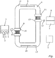
Fig. 1 a schematic view of a cooling device according to the present invention. -
Fig. 1 shows, in a schematic view, acooling device 1 for a vehicle. Thus, in a completely assembled state of the vehicle, the vehicle comprises thecooling device 1. In the embodiment shown inFig. 1 , the vehicle is configured as a motor vehicle. Preferably, the vehicle is configured as a passenger vehicle. In its completely assembled state, the vehicle comprises at least onefirst component 2 which may be a part of thecooling device 1. Thefirst component 2 comprises aninternal combustion engine 3 which is particularly schematically shown inFig. 1 . The internal combustion engine 3 (ICE) is configured to drive the vehicle in a fired mode or a fired operation of theinternal combustion engine 3. During the fired operation, combustion processes take place incombustion chambers 4 of theinternal combustion engine 3. Therespective combustion chamber 4 may be bound by a respective cylinder of theinternal combustion engine 3. In the respective combustion process, a mixture of air and fuel is burned thereby producing exhaust gas of theinternal combustion engine 3. The exhaust gas comprises heat which is also referred to as waste heat of theinternal combustion engine 3. The exhaust gas is guided out of therespective combustion chamber 4 such that theinternal combustion engine 3 and thus thefirst component 2 provide the exhaust gas and thus said waste heat. - In the embodiment shown in
Fig. 1 , the vehicle is configured as a hybrid vehicle. This means the vehicle also comprises at least oneelectric machine 5 which is particularly schematically shown inFig. 1 . Theelectric machine 5 may be operated in a motor mode and thus as an electric motor by which the vehicle may be electrically driven. Moreover, the vehicle further comprises at least onesecond component 6 which comprises at least oneenergy storage 7. For example, theenergy storage 7 is a battery, in particular a high voltage battery. Theenergy storage 7 is configured to electrochemically store electrical energy (i.e. electric current). Moreover, theenergy storage 7 is configured to provide the electrical energy stored in theenergy storage 7. Moreover, theelectric machine 5 is configured to receive the electrical energy provided by theenergy storage 7. Thus, theelectric machine 5 may be supplied with the electrical energy stored in theenergy storage 7. By supplying theelectric machine 5 with the electrical energy stored in and provided by theenergy storage 7, theelectric machine 5 may be or is operated in said motor mode. - In order to realize a particularly energy-efficient operation of the vehicle, the
cooling device 1 comprises at least onethermoacoustic converter 8 configured to convert the waste heat provided by thefirst component 2 into acoustic waves illustrated by anarrow 9. As illustrated by thearrow 9, thethermoacoustic converter 8 is also configured to provide the acoustic waves generated, from the waste heat, by thethermoacoustic converter 8. As illustrated by anarrow 10, the waste heat is provided by thefirst component 2. Moreover, for example, thethermoacoustic converter 8 is configured to receive the waste heat. - Moreover, the
cooling device 1 comprises at least onethermoacoustic heat pump 11 which is configured to receive the acoustic waves provided by thethermoacoustic converter 8. Moreover, thethermoacoustic heat pump 11 is configured to use the received acoustic waves to cool at least one cooling fluid for cooling thesecond component 6 and thus theenergy storage 7. The cooling fluid is also referred to as a refrigerant. For example, the cooling fluid, in particular the cooled cooling fluid, is illustrated by anarrow 12. Thus, for example thethermoacoustic heat pump 11 is configured to provide the cooled cooling fluid. For example, thesecond component 6 is configured to receive the cooled cooling fluid such that thesecond component 6 may be cooled by the cooled cooling fluid. - As shown in
Fig. 1 , thecooling device 1 may comprise aloop pipe 13 which is also referred to as a main loop pipe. Thethermoacoustic converter 8 and thethermoacoustic heat pump 11 are arranged in theloop pipe 13 through or in which the acoustic waves provided by thethermoacoustic converter 8 may propagate. For example, theloop pipe 13 comprises at least oneduct element 14 by which the acoustic waves provided by thethermoacoustic converter 8 are guided, in particular from thethermoacoustic converter 8, to thethermoacoustic heat pump 11. Preferably, in theduct element 14, in particular in theloop pipe 13, a working medium is received or arranged. Preferably, the working medium is a working fluid which may be configured as a working gas. The acoustic waves provided by thethermoacoustic converter 8 are guided, transferred or transported by the working medium inside theduct element 14, in particular theloop pipe 13, to thethermoacoustic heat pump 11. Preferably, the working medium is air, in particular humid air. As shown inFig. 1 and illustrated by thearrow 9 and afurther arrow 15, the acoustic waves may be guided in a circle by theloop pipe 13 and inside theloop pipe 13. Thus, a particularly efficient operation of thecooling device 1 may be realized. - For example, the
thermoacoustic converter 8 may comprise afirst heat exchanger 16 through which the waste heat or the exhaust gas and thus the waste heat can flow. In other words, a transfer medium, in particular a transfer fluid, for transporting the waste heat can flow through theheat exchanger 16. For example, the transfer medium is the exhaust gas of theinternal combustion engine 3. Thus, for example, the waste heat is contained in the transfer medium. Via theheat exchanger 16, the heat contained in the transfer medium may be transferred to the working medium received in theloop pipe 13 thereby heating the working medium or generating temperature differences of the working medium arranged in theloop pipe 13 and thus generating the acoustic waves. - Alternatively or additionally, the
thermoacoustic heat pump 11 may comprise asecond heat exchanger 17 through which the cooling fluid can flow. Via theheat exchanger 17 or by theheat exchanger 17 the cooling fluid is cooled by using the acoustic waves and the thermoacoustic effect. In other words, thethermoacoustic heat pump 11 uses the acoustic waves provided by thethermoacoustic converter 8 to cool the cooling fluid flowing through thethermoacoustic heat pump 11, in particular theheat exchanger 17. Thus, thethermoacoustic heat pump 11 may provide the cooled cooling fluid by which thesecond component 6, in particular theenergy storage 7, may be cooled. Thus, an excessive use of electrical energy stored in theenergy storage 7 for cooling thesecond component 6 may be avoided such that a particularly high range over which the vehicle may be electrically driven by theelectric machine 5 may be realized. -
- 1
- cooling device
- 2
- first component
- 3
- internal combustion engine
- 4
- combustion chamber
- 5
- electric machine
- 6
- second component
- 7
- energy storage
- 8
- thermoacoustic converter
- 9
- arrow
- 10
- arrow
- 11
- thermoacoustic heat pump
- 12
- arrow
- 13
- loop pipe
- 14
- duct element
- 15
- arrow
- 16
- first heat exchanger
- 17
- second heat exchanger
Claims (11)
- A cooling device (1) for a vehicle, the cooling device (1) comprising:- at least one thermoacoustic converter (8) configured to convert waste heat (10) from at least one first component (2) of the vehicle into at least one acoustic waves (9) and to provide the acoustic waves (9), and- at least one thermoacoustic heat pump (11) configured to receive the acoustic waves (9) and to use the received acoustic waves (9) to cool at least one cooling fluid (12) for cooling at least one second component (6) of the vehicle.
- The cooling device (1) according to claim 1,
wherein the thermoacoustic converter (8) and the thermoacoustic heat pump (11) are spaced away from each other. - The cooling device (1) according to claim 1 or 2,
wherein the cooling device (1) comprises the first component (2). - The cooling device (1) according to claim 3,
wherein the first component (2) comprises an internal combustion engine (3) configured to drive the vehicle. - The cooling device (1) according to claim 3,
wherein the first component (2) comprises an energy storage (7) configured to store and provide electrical energy for operating an electric machine (7) for driving the vehicle. - The cooling device (1) according to any one of the preceding claims,
wherein the cooling device (1) comprises the second component (6). - The cooling device (1) according to claim 6,
wherein the second component (6) comprises an energy storage (7) configured to store and provide electrical energy for operating an electric machine (5) for driving the vehicle. - The cooling device (1) according to claim 5 or 7,
wherein the energy storage (7) is configured to electrochemically storing the electrical energy and comprises a solid electrolyte for providing the electrical energy. - The cooling device (1) according to any one of claims 6 to 8,
wherein the second component (6) comprises:- the interior of the vehicle, and/or- at least one heat exchanger of an air conditioning device of the vehicle, the heat exchanger being configured to transfer heat from air to the cooling fluid (12) thereby cooling the air, wherein the air conditioning device is configured to introduce the cooled air into the interior of the vehicle, and/or- at least one electric machine (5) configured to drive the vehicle, and/or- an electronic control unit configured to control a charging procedure for charging an energy storage (7) configured to store and provide electrical energy for operating an electric machine (5) for driving the vehicle, and/or- a charging device for charging an energy storage (7) configured to store and provide electrical energy for operating an electric machine (5) for driving the vehicle - The cooling device (1) according to any one of the preceding claims,
wherein the cooling fluid (12) is a gas or a liquid. - A vehicle comprising a cooling device (1) which comprises:- at least one thermoacoustic converter (8) configured to convert waste heat (10) from at least one first component (2) of the vehicle into acoustic waves (9) and to provide the acoustic waves (9), and- at least one thermoacoustic heat pump (11) configured to receive the acoustic waves (9) and to use the received acoustic waves (9) to cool at least one cooling fluid (12) for cooling at least one second component (6) of the vehicle.
Priority Applications (1)
| Application Number | Priority Date | Filing Date | Title |
|---|---|---|---|
| EP21156597.3A EP4043704A1 (en) | 2021-02-11 | 2021-02-11 | Vehicle |
Applications Claiming Priority (1)
| Application Number | Priority Date | Filing Date | Title |
|---|---|---|---|
| EP21156597.3A EP4043704A1 (en) | 2021-02-11 | 2021-02-11 | Vehicle |
Publications (1)
| Publication Number | Publication Date |
|---|---|
| EP4043704A1 true EP4043704A1 (en) | 2022-08-17 |
Family
ID=74591881
Family Applications (1)
| Application Number | Title | Priority Date | Filing Date |
|---|---|---|---|
| EP21156597.3A Withdrawn EP4043704A1 (en) | 2021-02-11 | 2021-02-11 | Vehicle |
Country Status (1)
| Country | Link |
|---|---|
| EP (1) | EP4043704A1 (en) |
Citations (12)
| Publication number | Priority date | Publication date | Assignee | Title |
|---|---|---|---|---|
| EP0447134A2 (en) * | 1990-03-14 | 1991-09-18 | MacroSonix Corp. | Standing wave compressor |
| US6032464A (en) * | 1999-01-20 | 2000-03-07 | Regents Of The University Of California | Traveling-wave device with mass flux suppression |
| EP1201906A2 (en) | 2000-10-16 | 2002-05-02 | Honda Giken Kogyo Kabushiki Kaisha | Exhaust heat energy recovery system for internal combustion engine |
| US6588224B1 (en) * | 2002-07-10 | 2003-07-08 | Praxair Technology, Inc. | Integrated absorption heat pump thermoacoustic engine refrigeration system |
| WO2003079042A2 (en) * | 2002-03-13 | 2003-09-25 | Georgia Tech Research Corporation | Travelling-wave thermoacoustic engines with internal combustion and associated methods |
| US20030192324A1 (en) * | 2002-04-10 | 2003-10-16 | Smith Robert W. M. | Thermoacoustic device |
| US20040093865A1 (en) * | 2002-03-13 | 2004-05-20 | Weiland Nathan Thomas | Traveling-wave thermoacoustic engines with internal combustion |
| JP2010286203A (en) | 2009-06-12 | 2010-12-24 | Isuzu Motors Ltd | Thermoacoustic engine |
| JP2011002152A (en) | 2009-06-18 | 2011-01-06 | Isuzu Motors Ltd | Thermoacoustic engine |
| US20160177802A1 (en) * | 2014-12-17 | 2016-06-23 | Sdmo Industries | Acoustic Energy Cooling Source |
| WO2017048116A1 (en) * | 2015-09-17 | 2017-03-23 | Soundenergy B.V. | Thermoacoustic energy conversion system |
| US20190226381A1 (en) * | 2016-10-06 | 2019-07-25 | Denso Corporation | Energy conversion device |
-
2021
- 2021-02-11 EP EP21156597.3A patent/EP4043704A1/en not_active Withdrawn
Patent Citations (12)
| Publication number | Priority date | Publication date | Assignee | Title |
|---|---|---|---|---|
| EP0447134A2 (en) * | 1990-03-14 | 1991-09-18 | MacroSonix Corp. | Standing wave compressor |
| US6032464A (en) * | 1999-01-20 | 2000-03-07 | Regents Of The University Of California | Traveling-wave device with mass flux suppression |
| EP1201906A2 (en) | 2000-10-16 | 2002-05-02 | Honda Giken Kogyo Kabushiki Kaisha | Exhaust heat energy recovery system for internal combustion engine |
| WO2003079042A2 (en) * | 2002-03-13 | 2003-09-25 | Georgia Tech Research Corporation | Travelling-wave thermoacoustic engines with internal combustion and associated methods |
| US20040093865A1 (en) * | 2002-03-13 | 2004-05-20 | Weiland Nathan Thomas | Traveling-wave thermoacoustic engines with internal combustion |
| US20030192324A1 (en) * | 2002-04-10 | 2003-10-16 | Smith Robert W. M. | Thermoacoustic device |
| US6588224B1 (en) * | 2002-07-10 | 2003-07-08 | Praxair Technology, Inc. | Integrated absorption heat pump thermoacoustic engine refrigeration system |
| JP2010286203A (en) | 2009-06-12 | 2010-12-24 | Isuzu Motors Ltd | Thermoacoustic engine |
| JP2011002152A (en) | 2009-06-18 | 2011-01-06 | Isuzu Motors Ltd | Thermoacoustic engine |
| US20160177802A1 (en) * | 2014-12-17 | 2016-06-23 | Sdmo Industries | Acoustic Energy Cooling Source |
| WO2017048116A1 (en) * | 2015-09-17 | 2017-03-23 | Soundenergy B.V. | Thermoacoustic energy conversion system |
| US20190226381A1 (en) * | 2016-10-06 | 2019-07-25 | Denso Corporation | Energy conversion device |
Similar Documents
| Publication | Publication Date | Title |
|---|---|---|
| CN113119688B (en) | Whole vehicle thermal management system of plug-in hybrid electric vehicle and control method thereof | |
| US11878606B2 (en) | Battery thermal management system for vehicle | |
| US8895172B2 (en) | Apparatus and method for controlling the temperature of a battery in a hybrid electric vehicle | |
| CN107017440B (en) | Battery thermal management system including thermoelectric device | |
| CN109070758B (en) | Battery temperature and charge regulation system and method | |
| CN103963605B (en) | Vehicle heat pump system and the method utilizing accumulation of heat | |
| US7550949B2 (en) | Process for controlling temperature of battery pack | |
| JPH07304338A (en) | Battery cooling device for electric vehicles | |
| KR101751673B1 (en) | Battery pack cooling system with preheating fuction | |
| CN109638386B (en) | Automobile and heating and power battery heating system and method | |
| JP2019055649A (en) | Battery temperature control system | |
| US20170324126A1 (en) | Effectively cooled battery assemblies | |
| CN1489535A (en) | Cooling system for fuel cell modules as part of on-board power supply | |
| JP2019064566A (en) | Battery heating system | |
| US9975438B2 (en) | Operating device and system for operating a motor vehicle | |
| EP4043704A1 (en) | Vehicle | |
| CN112550003B (en) | Range extender of electric vehicle | |
| CN118589079A (en) | Battery assembly, vehicle and method having gas manifold liner and battery tray seal | |
| KR102710200B1 (en) | System to applicate recovery of waste heat for fuel cell electric vehicle | |
| JP2014150055A (en) | Combined battery system and electrically propelled vehicle | |
| JP6249347B2 (en) | Battery system | |
| US20040000441A1 (en) | Motor vehicle with a drive assembly and with an operating medium reservoir | |
| EP1832465A2 (en) | Motor vehicle comprising an internal combustion engine and an auxiliary fuel cell power plant and method for operating the same | |
| CN116476599B (en) | Vehicle thermal management system and vehicle | |
| JP2007302123A (en) | Car |
Legal Events
| Date | Code | Title | Description |
|---|---|---|---|
| PUAI | Public reference made under article 153(3) epc to a published international application that has entered the european phase |
Free format text: ORIGINAL CODE: 0009012 |
|
| STAA | Information on the status of an ep patent application or granted ep patent |
Free format text: STATUS: THE APPLICATION HAS BEEN PUBLISHED |
|
| AK | Designated contracting states |
Kind code of ref document: A1 Designated state(s): AL AT BE BG CH CY CZ DE DK EE ES FI FR GB GR HR HU IE IS IT LI LT LU LV MC MK MT NL NO PL PT RO RS SE SI SK SM TR |
|
| STAA | Information on the status of an ep patent application or granted ep patent |
Free format text: STATUS: THE APPLICATION IS DEEMED TO BE WITHDRAWN |
|
| P01 | Opt-out of the competence of the unified patent court (upc) registered |
Effective date: 20230523 |
|
| 18D | Application deemed to be withdrawn |
Effective date: 20230218 |