EP4043674B1 - Brush for automatic pool cleaners - Google Patents
Brush for automatic pool cleaners Download PDFInfo
- Publication number
- EP4043674B1 EP4043674B1 EP22165827.1A EP22165827A EP4043674B1 EP 4043674 B1 EP4043674 B1 EP 4043674B1 EP 22165827 A EP22165827 A EP 22165827A EP 4043674 B1 EP4043674 B1 EP 4043674B1
- Authority
- EP
- European Patent Office
- Prior art keywords
- pool
- brush
- cleaning brush
- scrubber
- shaft
- Prior art date
- Legal status (The legal status is an assumption and is not a legal conclusion. Google has not performed a legal analysis and makes no representation as to the accuracy of the status listed.)
- Active
Links
Images


Classifications
-
- E—FIXED CONSTRUCTIONS
- E04—BUILDING
- E04H—BUILDINGS OR LIKE STRUCTURES FOR PARTICULAR PURPOSES; SWIMMING OR SPLASH BATHS OR POOLS; MASTS; FENCING; TENTS OR CANOPIES, IN GENERAL
- E04H4/00—Swimming or splash baths or pools
- E04H4/14—Parts, details or accessories not otherwise provided for
- E04H4/16—Parts, details or accessories not otherwise provided for specially adapted for cleaning
- E04H4/1654—Self-propelled cleaners
-
- A—HUMAN NECESSITIES
- A46—BRUSHWARE
- A46B—BRUSHES
- A46B13/00—Brushes with driven brush bodies or carriers
- A46B13/008—Disc-shaped brush bodies
-
- A—HUMAN NECESSITIES
- A46—BRUSHWARE
- A46B—BRUSHES
- A46B13/00—Brushes with driven brush bodies or carriers
- A46B13/02—Brushes with driven brush bodies or carriers power-driven carriers
-
- A—HUMAN NECESSITIES
- A46—BRUSHWARE
- A46B—BRUSHES
- A46B7/00—Bristle carriers arranged in the brush body
- A46B7/04—Bristle carriers arranged in the brush body interchangeably removable bristle carriers
- A46B7/042—Clip or snap connection for bristle carriers
-
- A—HUMAN NECESSITIES
- A46—BRUSHWARE
- A46B—BRUSHES
- A46B7/00—Bristle carriers arranged in the brush body
- A46B7/04—Bristle carriers arranged in the brush body interchangeably removable bristle carriers
- A46B7/044—Sliding connections for bristle carriers
-
- A—HUMAN NECESSITIES
- A46—BRUSHWARE
- A46B—BRUSHES
- A46B9/00—Arrangements of the bristles in the brush body
- A46B9/02—Position or arrangement of bristles in relation to surface of the brush body, e.g. inclined, in rows, in groups
-
- E—FIXED CONSTRUCTIONS
- E04—BUILDING
- E04H—BUILDINGS OR LIKE STRUCTURES FOR PARTICULAR PURPOSES; SWIMMING OR SPLASH BATHS OR POOLS; MASTS; FENCING; TENTS OR CANOPIES, IN GENERAL
- E04H4/00—Swimming or splash baths or pools
- E04H4/14—Parts, details or accessories not otherwise provided for
- E04H4/16—Parts, details or accessories not otherwise provided for specially adapted for cleaning
- E04H4/1654—Self-propelled cleaners
- E04H4/1663—Self-propelled cleaners the propulsion resulting from an intermittent interruption of the waterflow through the cleaner
-
- A—HUMAN NECESSITIES
- A46—BRUSHWARE
- A46B—BRUSHES
- A46B2200/00—Brushes characterized by their functions, uses or applications
- A46B2200/30—Brushes for cleaning or polishing
-
- E—FIXED CONSTRUCTIONS
- E04—BUILDING
- E04H—BUILDINGS OR LIKE STRUCTURES FOR PARTICULAR PURPOSES; SWIMMING OR SPLASH BATHS OR POOLS; MASTS; FENCING; TENTS OR CANOPIES, IN GENERAL
- E04H4/00—Swimming or splash baths or pools
- E04H4/14—Parts, details or accessories not otherwise provided for
- E04H4/16—Parts, details or accessories not otherwise provided for specially adapted for cleaning
- E04H4/1618—Hand-held powered cleaners
- E04H4/1636—Suction cleaners
Definitions
- This invention relates to automatic pool cleaners (APCs) configured to move autonomously within liquid-containing bodies such as swimming pools and spas and more particularly, although not necessarily exclusively, to components of APCs that frictionally contact surfaces of the pools and spas.
- APCs automatic pool cleaners
- a pool-cleaning brush of such an APC is known from EP2706170 A2 .
- an exemplary scrubber may include blades, a shaft, and optionally a gear.
- [the] scrubber desirably rotates about [the] shaft so as to move water ... toward [an] inlet of [a] body of [an] automatic pool cleaner.
- Such rotation may be caused by interaction of [the] gear with a corresponding gear or other device typically located within [the] body.
- a wear surface Also described in the van der Meijden application as another optional part of a scrubber is a "wear surface.” If present, the wear surface may be located centrally among the blades of the scrubber and coaxial with the shaft. At least at times in use, the wear surface may contact a surface to be cleaned. See id. , p. 2, ⁇ 0028.
- the present invention provides these types of brushes useful especially (although not necessarily exclusively) with the scrubbers and APCs of the types identified in the van der Meijden application.
- Brushes of the invention may clip to a hub of a scrubber so as to attach to, and detach from, the scrubber easily.
- the brushes also preferably flex when a scrubber rotates.
- the brushes include fingers having bristles protruding outward on both opposed sides of the fingers. Prior to rotation of the scrubbers, the fingers nominally are generally perpendicular to the surface on which the associated APC rests. As scrubbers rotate, however, the fingers flex ( e.g. lay over) and become more parallel to the surface. Flexing of the fingers in this manner in turn causes bristles on one side of fingers to become more perpendicular to the surface, thus readily frictionally contacting it.
- Brushes may be attached as desired to a scrubber.
- a scrubber Presently preferred is that at least two brushes be used with a scrubber and positioned symmetrically about the shaft. Fewer or more than two brushes may be used in connection with any particular scrubber, however, and conceivably more than one brush may be attached in a particular location.
- FIGS. 1A-B Depicted in FIGS. 1A-B is exemplary scrubber 10.
- Scrubber 10 which is generally similar to scrubbers of the van der Meijden application, may include blades 14 and shaft 18. Also illustrated in FIGS. 1A-B is hub 20 interconnecting blades 14 and shaft 18.
- scrubber 10 desirably rotates about shaft 18 so as to move water toward an inlet 21 of a cleaner such as APC 22 ( see FIG. 5 ).
- APC 22 When the APC 22 is upright on a bottom surface of a pool, shaft 18 will be generally perpendicular to the plane of the bottom surface and thus scrubber 10 will rotate about an axis perpendicular (or generally so) to the bottom surface.
- blades 14 preferably are "semi-rigid” in nature, meaning that they have sufficient flexibility to accommodate passage into inlet 21 of APC 22, without blockage, of at least some larger types of debris often found in outdoor swimming pools.
- the term "semi-rigid” also means that blades 14 nevertheless have sufficient rigidity to move volumes of water toward the inlet 21 of the cleaner as they rotate about shaft 18.
- a presently-preferred material from which blades 14 is made remains molded thermoplastic polyurethane, although other materials may be used instead.
- Scrubber 10 advantageously may include six blades 14 extending radially from shaft 18. Fewer or greater numbers of blades 14 may be employed as appropriate, however. As illustrated in FIG. 5 , two scrubbers 10 preferably are employed as part of APC 22, with each scrubber 10 being positioned at least partly to a side of inlet 21 of the APC 22. Again, though, fewer or greater numbers of scrubbers 10 may be utilized, and each or any scrubber 10 may be positioned in any suitable location.
- FIG. 1A many of the six blades 14 are circumferentially spaced approximately forty-five degrees, rather than approximately sixty degrees, from adjacent blades 14. This is because attachment assemblies 26 of hub 20 have, in effect, replaced the seventh and eighth blades.
- the two attachment assemblies 26 are at least partially visible in FIG. 1A spaced circumferentially about shaft 18 by approximately one hundred eighty degrees. Symmetrical positioning of attachment assemblies 26 about shaft 18 presently is preferred, although situations may arise in which an odd number of assemblies 26, or asymmetrical positioning of an even number of assemblies 26, is desired.
- the exemplary attachment assembly 26 of FIG. 1A may comprise at least one recess 30A.
- recess 30A is formed by a pair of spaced walls 34A-B connected to hub 20.
- FIGS. 2A-C Shown especially in FIGS. 2A-C is exemplary brush 42.
- member 46 which is sized and shaped to be frictionally fitted into recesses 30A and 30B.
- clips 50 of brush 42 frictionally slide along walls 34A-B and 38A-B.
- Manipulating brush 42 in this manner connects the brush 42 to scrubber 10 for use--as shown in FIGS. 3-5 .
- brush 42 is likely to wear through use, it preferably may be detached from scrubber 42 (as through manual force, for example) for replacement.
- brush body 54 Also included as parts of brush 42 are brush body 54, fingers 58, and bristles 62.
- Fingers 58 depend from body 54, with each finger 58 comprising opposed major sides 66A-B. Bristles 52 protrude outward from these major sides 66A-B.
- FIGS. 2A-5 illustrate three fingers 58 depending from each body 54, more or fewer fingers 58 may be present instead if appropriate or desired.
- Fingers 58 beneficially are flexible. Accordingly, as shown in FIG. 4 , fingers 58 may flex as blades 14 rotate about shaft 18. Whereas major sides 66A-B are nominally vertical when APC is upright (e.g. FIG. 5 ) and blades 14 are not rotating, flexing of fingers 58 causes major sides 66A-B to become more closely parallel to the surface to be cleaned. Consequently, because bristles 52 protrude outward from major sides 66A-B, these bristles 52 become more closely perpendicular to the to-be-cleaned surface as the fingers 58 flex.
- Bristles 52 thus in use may contact the to-be-cleaned surface so as to "scrub" the surface and suspend bottom-dwelling debris into the water of the pool for evacuation into inlet 21 of APC 22.
- APC 22 also may include body 70 through which the evacuated water may flow to outlet 74 and then into a hose, all under influence of a pump.
- bristles 52 need necessarily be present only on whichever of major sides 66A or 66B is the "leading" side for purpose of the rotation (as the other, "trailing" major side will flex away from the to-be-cleaned surface). It nevertheless may be advantageous to include bristles 52 on the trailing major side 66B or 66A of brush 42 so that, when bristles 52 on the leading side wear, brush 42 may be switched to a circumferentially opposite location on scrubber 10 so that the previously-trailing side becomes the leading side and presents unworn bristles 52 to the to-be-cleaned surface. This switch effectively can double the useful life of a brush 42. (And of course, if scrubber 10 ever is configured to rotate both clockwise and counterclockwise, including bristles 52 on both major sides 66A-B may be valuable.)
- any reference to “pool” herein may include a spa, hot tub, or other vessel in which water is placed for swimming, bathing, therapy, or recreation.
Landscapes
- Engineering & Computer Science (AREA)
- Architecture (AREA)
- Civil Engineering (AREA)
- Structural Engineering (AREA)
- Cleaning In General (AREA)
- Brushes (AREA)
- Nozzles For Electric Vacuum Cleaners (AREA)
Description
- This invention relates to automatic pool cleaners (APCs) configured to move autonomously within liquid-containing bodies such as swimming pools and spas and more particularly, although not necessarily exclusively, to components of APCs that frictionally contact surfaces of the pools and spas.
- A pool-cleaning brush of such an APC is known from
EP2706170 A2 . - Commonly-owned
U.S. Patent Application Publication No. 2011/0314617 of van der Meijden, et al. , discloses various components of APCs. Among components illustrated in the van der Meijden application are devices referenced as "scrubbers." As detailed in the van der Meijden application, an exemplary scrubber may include blades, a shaft, and optionally a gear. - In use, [the] scrubber desirably rotates about [the] shaft so as to move water ... toward [an] inlet of [a] body of [an] automatic pool cleaner. Such rotation may be caused by interaction of [the] gear with a corresponding gear or other device typically located within [the] body.
- See van der Meijden, pp. 1-2, ¶ 0026 (numerals omitted). The rotation and evacuation of water entering the inlet additionally produces "down force" tending to enhance traction of the APC as it moves along a surface within a pool.
- Also described in the van der Meijden application as another optional part of a scrubber is a "wear surface." If present, the wear surface may be located centrally among the blades of the scrubber and coaxial with the shaft. At least at times in use, the wear surface may contact a surface to be cleaned. See id., p. 2, ¶ 0028.
- Even though the van der Meijden application contemplates frictional contact between the wear surface and surfaces of a pool or spa, additional scrubbing action may be desirable--at least at times--for cleaning purposes. Including brushes spaced from (i.e. not coaxial with) the shaft of a scrubber also may be advantageous, as may be utilizing bristles which contact a surface as the scrubber rotates about the shaft. Removably attaching the brushes to a scrubber further may be beneficial, as in such cases the brushes may be removed from the scrubber when not needed.
- The present invention provides these types of brushes useful especially (although not necessarily exclusively) with the scrubbers and APCs of the types identified in the van der Meijden application. Brushes of the invention may clip to a hub of a scrubber so as to attach to, and detach from, the scrubber easily. The brushes also preferably flex when a scrubber rotates.
- The brushes include fingers having bristles protruding outward on both opposed sides of the fingers. Prior to rotation of the scrubbers, the fingers nominally are generally perpendicular to the surface on which the associated APC rests. As scrubbers rotate, however, the fingers flex (e.g. lay over) and become more parallel to the surface. Flexing of the fingers in this manner in turn causes bristles on one side of fingers to become more perpendicular to the surface, thus readily frictionally contacting it.
- Because in use scrubbers of the present invention rotate about an axis generally perpendicular to the pool surface, their brush speeds relative to the surface are faster than those of passive devices (which typically are dragged along the surface) or rollers (which typically rotate about an axis parallel to the surface and in the same direction as the wheels of the cleaner). Such rotation also requires less surface-area contact between the brushes and pool surface to scrub an equivalent width of pool surface than would a roller, whose length must span that entire width. This decreased surface-area contact of the brushes produces less resistance on the drive system of the APC than would rollers, potentially enhancing the longevity and robustness of the drive system.
- Brushes may be attached as desired to a scrubber. Presently preferred is that at least two brushes be used with a scrubber and positioned symmetrically about the shaft. Fewer or more than two brushes may be used in connection with any particular scrubber, however, and conceivably more than one brush may be attached in a particular location.
- It thus is an optional, non-exclusive object of the present invention to provide components for APCs.
- It also is an optional, non-exclusive object of the present invention to provide improvements to scrubbers of the type identified in the van der Meijden application.
- It is another optional, non-exclusive object of the present invention to provide brushes configured to contact to-be-cleaned surfaces.
- It is an additional optional, non-exclusive object of the present invention to provide brushes that may clip to scrubbers so as to rotate as the blades rotate.
- It is, moreover, an optional, non-exclusive object of the present invention to provide brushes that include flexible fingers with bristles protruding therefrom.
- It is a further optional, non-exclusive object of the present invention to provide brushes whose fingers flex as their associated blades rotate, thus causing contact between their bristles and a to-be-cleaned surface of a pool or spa.
- It is yet another optional, non-exclusive object of the present invention to provide brushes which rotate about an axis perpendicular to the to-be-cleaned surface so as to produce faster speeds and less load on drive systems than do certain passive devices and rollers.
- Other objects, features, and advantages of the present invention will be apparent to those skilled in relevant fields with reference to the remaining text and the drawings of this application.
-
-
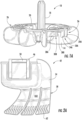
FIGS. 1A is an elevational view of an exemplary scrubber similar to that of those of the van der Meijden application. -
FIG. 1B is a perspective view of the scrubber ofFIG. 1A . -
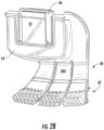
FIGS. 2A-C are various views of an exemplary brush configured to attach to the scrubber ofFIG. 1A . -
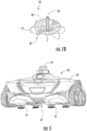
FIG. 3 is an elevational view of the scrubber ofFIG. 1A to which two brushes ofFIGS. 2A-C have been attached. -
FIG. 4 is a perspective view of the scrubber ofFIG. 1A to which one brush ofFIGS. 2A-C has been attached for purposes of showing its flexibility. -
FIG. 5 is a perspective view of an APC including two scrubbers, to each of which brushes have been attached in a manner similar toFIG. 3 . - Depicted in
FIGS. 1A-B isexemplary scrubber 10.Scrubber 10, which is generally similar to scrubbers of the van der Meijden application, may includeblades 14 andshaft 18. Also illustrated inFIGS. 1A-B ishub 20 interconnectingblades 14 andshaft 18. In use, scrubber 10 desirably rotates aboutshaft 18 so as to move water toward aninlet 21 of a cleaner such as APC 22 (seeFIG. 5 ). When theAPC 22 is upright on a bottom surface of a pool,shaft 18 will be generally perpendicular to the plane of the bottom surface and thusscrubber 10 will rotate about an axis perpendicular (or generally so) to the bottom surface. - Consistent with the discussion in the van der Meijden application,
blades 14 preferably are "semi-rigid" in nature, meaning that they have sufficient flexibility to accommodate passage intoinlet 21 ofAPC 22, without blockage, of at least some larger types of debris often found in outdoor swimming pools. The term "semi-rigid" also means thatblades 14 nevertheless have sufficient rigidity to move volumes of water toward theinlet 21 of the cleaner as they rotate aboutshaft 18. A presently-preferred material from whichblades 14 is made remains molded thermoplastic polyurethane, although other materials may be used instead. -
Scrubber 10 advantageously may include sixblades 14 extending radially fromshaft 18. Fewer or greater numbers ofblades 14 may be employed as appropriate, however. As illustrated inFIG. 5 , twoscrubbers 10 preferably are employed as part ofAPC 22, with eachscrubber 10 being positioned at least partly to a side ofinlet 21 of theAPC 22. Again, though, fewer or greater numbers ofscrubbers 10 may be utilized, and each or anyscrubber 10 may be positioned in any suitable location. - As shown in
FIG. 1A , many of the sixblades 14 are circumferentially spaced approximately forty-five degrees, rather than approximately sixty degrees, fromadjacent blades 14. This is becauseattachment assemblies 26 ofhub 20 have, in effect, replaced the seventh and eighth blades. The twoattachment assemblies 26 are at least partially visible inFIG. 1A spaced circumferentially aboutshaft 18 by approximately one hundred eighty degrees. Symmetrical positioning ofattachment assemblies 26 aboutshaft 18 presently is preferred, although situations may arise in which an odd number ofassemblies 26, or asymmetrical positioning of an even number ofassemblies 26, is desired. - The
exemplary attachment assembly 26 ofFIG. 1A may comprise at least onerecess 30A. In the version ofscrubber 10 depicted inFIG. 1A ,recess 30A is formed by a pair of spacedwalls 34A-B connected tohub 20. Asecond recess 30B, formed by a pair of spacedwalls 38A-B connected tohub 20, also appears inFIG. 1A . - Shown especially in
FIGS. 2A-C isexemplary brush 42. Included as part ofbrush 42 ismember 46, which is sized and shaped to be frictionally fitted intorecesses brush 42 frictionally slide alongwalls 34A-B and 38A-B. Manipulating brush 42 in this manner connects thebrush 42 to scrubber 10 for use--as shown inFIGS. 3-5 . Becausebrush 42 is likely to wear through use, it preferably may be detached from scrubber 42 (as through manual force, for example) for replacement. - Also included as parts of
brush 42 arebrush body 54,fingers 58, and bristles 62.Fingers 58 depend frombody 54, with eachfinger 58 comprising opposedmajor sides 66A-B. Bristles 52 protrude outward from thesemajor sides 66A-B. AlthoughFIGS. 2A-5 illustrate threefingers 58 depending from eachbody 54, more orfewer fingers 58 may be present instead if appropriate or desired. -
Fingers 58 beneficially are flexible. Accordingly, as shown inFIG. 4 ,fingers 58 may flex asblades 14 rotate aboutshaft 18. Whereasmajor sides 66A-B are nominally vertical when APC is upright (e.g.FIG. 5 ) andblades 14 are not rotating, flexing offingers 58 causesmajor sides 66A-B to become more closely parallel to the surface to be cleaned. Consequently, because bristles 52 protrude outward frommajor sides 66A-B, these bristles 52 become more closely perpendicular to the to-be-cleaned surface as thefingers 58 flex. Bristles 52 thus in use may contact the to-be-cleaned surface so as to "scrub" the surface and suspend bottom-dwelling debris into the water of the pool for evacuation intoinlet 21 ofAPC 22. Consistent with other suction-type APCs,APC 22 also may includebody 70 through which the evacuated water may flow tooutlet 74 and then into a hose, all under influence of a pump. - Moreover, because
scrubber 10 rotates about an axis perpendicular to the to-be-cleaned surface, the speed of movement of brushes 42 (and hence of bristles 52) relative to the surface may be faster than that of passive devices which merely are dragged along the surface. This relative speed of movement likewise may be faster than that of rollers, which typically rotate about axes parallel to the surface and in the same direction as the wheels or tracks of an associated cleaner. Rotation ofscrubber 10 about the perpendicular axis also requires approximately fifty percent less surface-area contact betweenbrushes 42 and the pool surface to scrub an equivalent width of pool surface than would a roller, whose length must span that entire width. This decreased surface-area contact ofbrushes 42 produces less resistance on the drive system ofAPC 22 than would rollers, potentially enhancing the longevity and robustness of the drive system. - If
scrubber 10 is configured to rotate only in one direction, bristles 52 need necessarily be present only on whichever ofmajor sides major side brush 42 so that, when bristles 52 on the leading side wear,brush 42 may be switched to a circumferentially opposite location onscrubber 10 so that the previously-trailing side becomes the leading side and presents unworn bristles 52 to the to-be-cleaned surface. This switch effectively can double the useful life of abrush 42. (And of course, ifscrubber 10 ever is configured to rotate both clockwise and counterclockwise, including bristles 52 on bothmajor sides 66A-B may be valuable.) - The foregoing is provided for purposes of illustrating, explaining, and describing embodiments of the present invention. Modifications and adaptations to these embodiments will be apparent to those skilled in the art and may be made without departing from the scope of the invention as defined by the appended claims. Also, although "pool" and "spa" are sometimes used separately, any reference to "pool" herein may include a spa, hot tub, or other vessel in which water is placed for swimming, bathing, therapy, or recreation.
Claims (10)
- A pool-cleaning brush (42) suitable for an automatic pool cleaner (22) comprising:a. a brush body (54);b. a first flexible finger (58) (i) depending from the brush body (54) and (ii) comprising opposed first and second major sides (66A, 66B);c. bristles (62) protruding outward from the first and second major sides,characterized in that the pool-cleaning brush (42) comprises clips (50) for connecting the brush body (54) to another component of an automatic pool cleaner (22).
- A pool-cleaning brush (42) according to claim 1 further comprising a friction fit member (46).
- A pool-cleaning brush (42) according to claim 2 wherein the friction fit member (46) is configured, in size and shape, to be frictionally fitted into recesses (30A, 30B) of an other component of the automatic pool cleaner.
- A pool-cleaning brush (42) according to claim 2 wherein the friction fit member (46) is part of connecting means.
- A pool-cleaning brush (42) according to claim 2 in which the clips (50) are two clips (50) which are positioned on opposite sides of the friction fit member (46).
- A pool-cleaning brush (42) according to claim 1 further comprising a second finger (58) depending from the brush body (54).
- A pool-cleaning brush (42) according to claim 1 further comprising second and third fingers (58) depending from the brush body (54).
- An automatic pool cleaner (22) comprising:a. a body (70) configured to travel along a surface to be cleaned;b. a shaft (18) positioned at least partially within the body (70) so as to be generally perpendicular to the surface as the body (70) travels therealong; andc. a pool-cleaning brush (42) according to claim 1, (i) displaced radially from the shaft (18), (ii) configured to rotate about the shaft (18), and (iii) configured to contact the surface as the body (70) travels therealong.
- An automatic pool cleaner (22) according to claim 6 in which the shaft (18) and a blade (14) are parts of a scrubber (10) also comprising a hub (20) interconnecting the shaft (18) and the blade (14), the hub (20) comprising an attachment assembly (26) configured to receive the pool-cleaning brush (42).
- An automatic pool cleaner (22) according to claim 6 in which the attachment assembly (26) comprises a recess (30A), and in which the friction fit member (46) of the pool-cleaning brush (42) is frictionally fitted into the recess (30A) to attach the pool-cleaning brush (42) to the hub (20).
Applications Claiming Priority (3)
| Application Number | Priority Date | Filing Date | Title |
|---|---|---|---|
| US14/711,499 US9920546B2 (en) | 2015-05-13 | 2015-05-13 | Components of automatic pool cleaners |
| EP16724825.1A EP3294970B1 (en) | 2015-05-13 | 2016-05-13 | Automatic pool cleaner |
| PCT/US2016/032302 WO2016183415A1 (en) | 2015-05-13 | 2016-05-13 | Components of automatic pool cleaners |
Related Parent Applications (2)
| Application Number | Title | Priority Date | Filing Date |
|---|---|---|---|
| EP16724825.1A Division EP3294970B1 (en) | 2015-05-13 | 2016-05-13 | Automatic pool cleaner |
| EP16724825.1A Division-Into EP3294970B1 (en) | 2015-05-13 | 2016-05-13 | Automatic pool cleaner |
Publications (2)
| Publication Number | Publication Date |
|---|---|
| EP4043674A1 EP4043674A1 (en) | 2022-08-17 |
| EP4043674B1 true EP4043674B1 (en) | 2024-09-11 |
Family
ID=56072471
Family Applications (2)
| Application Number | Title | Priority Date | Filing Date |
|---|---|---|---|
| EP22165827.1A Active EP4043674B1 (en) | 2015-05-13 | 2016-05-13 | Brush for automatic pool cleaners |
| EP16724825.1A Active EP3294970B1 (en) | 2015-05-13 | 2016-05-13 | Automatic pool cleaner |
Family Applications After (1)
| Application Number | Title | Priority Date | Filing Date |
|---|---|---|---|
| EP16724825.1A Active EP3294970B1 (en) | 2015-05-13 | 2016-05-13 | Automatic pool cleaner |
Country Status (6)
| Country | Link |
|---|---|
| US (3) | US9920546B2 (en) |
| EP (2) | EP4043674B1 (en) |
| AU (1) | AU2016260334B2 (en) |
| ES (2) | ES2992184T3 (en) |
| WO (1) | WO2016183415A1 (en) |
| ZA (1) | ZA201707219B (en) |
Families Citing this family (14)
| Publication number | Priority date | Publication date | Assignee | Title |
|---|---|---|---|---|
| US9920546B2 (en) | 2015-05-13 | 2018-03-20 | Zodiac Pool Systems Llc | Components of automatic pool cleaners |
| USD796758S1 (en) * | 2016-01-08 | 2017-09-05 | Zodiac Pool Systems, Inc. | Brush for pool cleaner |
| AU2017324272B2 (en) | 2016-09-06 | 2022-12-01 | Zodiac Pool Systems Llc | Buoyant automatic cleaners |
| US10301837B2 (en) * | 2016-11-04 | 2019-05-28 | Aqua Products, Inc. | Drive module for submersible autonomous vehicle |
| US10858853B2 (en) * | 2018-07-03 | 2020-12-08 | Zodiac Pool Systems Llc | Autonomous active waterline scrubbing device principally for swimming pools and spas |
| EP3599311B1 (en) | 2018-07-25 | 2026-03-11 | Techtronic Outdoor Products Technology Limited | Outdoor surface treating apparatus and associated accessory tool assembly |
| US11441326B2 (en) * | 2019-09-12 | 2022-09-13 | Upward Sales Limited | Pool cleaning vehicle |
| CN110670918B (en) * | 2019-09-24 | 2021-08-24 | 浙江斯普泳池有限公司 | A swimming pool cleaning device |
| CN215254937U (en) * | 2021-01-26 | 2021-12-21 | 佛山市顺德区一拓电气有限公司 | Transmission mechanism and cleaning device |
| USD962567S1 (en) * | 2021-12-16 | 2022-08-30 | Qianbing Tang | Swimming pool cleaner robot |
| US12286808B2 (en) * | 2022-10-12 | 2025-04-29 | Ningbo Poolstar Pool Products Co., Ltd. | Underwater cleaning robot |
| US20240401357A1 (en) | 2023-06-02 | 2024-12-05 | Zodiac Pool Systems Llc | Automatic swimming pool cleaner for swimming pools and spas |
| WO2025253348A1 (en) * | 2024-06-07 | 2025-12-11 | Zodiac Pool Care Europe | Automatic swimming pool cleaner system having removable with brushes |
| WO2026050133A1 (en) * | 2024-08-29 | 2026-03-05 | Zodiac Pool Systems Llc | Turbine brush clip for swimming pool cleaners |
Family Cites Families (56)
| Publication number | Priority date | Publication date | Assignee | Title |
|---|---|---|---|---|
| US3324492A (en) | 1965-08-05 | 1967-06-13 | Robert R Myers | Swimming pool cleaning means |
| US3398422A (en) * | 1968-01-25 | 1968-08-27 | Multi Clean Products Inc | Rotary brush for carpet scrubbing machine |
| JPS51130074A (en) * | 1975-05-06 | 1976-11-12 | Kiichi Hirata | Apparatus for cleaning off substances adhering to vessels or construct ions below the water surface |
| US4137590A (en) * | 1977-08-02 | 1979-02-06 | Milliken Research Corporation | Device for scrubbing carpet |
| USD271816S (en) | 1980-11-10 | 1983-12-13 | Price Kenneth E | Vacuum head for cleaning underwater surfaces |
| CA1200955A (en) * | 1983-03-22 | 1986-02-25 | Heinz W. Braukmann | Vacuum head for cleaning underwater surfaces |
| GB2154433B (en) | 1984-02-27 | 1988-06-08 | West Tsusho Co Ltd | Underwater cleaning apparatus |
| GB2166342B (en) | 1984-10-06 | 1988-02-10 | Gerritt Broersz | Underwater scouring apparatus |
| ES2040353T3 (en) * | 1987-10-23 | 1993-10-16 | Matsushita Electric Industrial Co., Ltd. | FLOOR SUCTION CUP FOR USE WITH A VACUUM CLEANER. |
| WO1995008459A1 (en) * | 1993-09-24 | 1995-03-30 | Clean Screen Wipers Pty. Ltd. | Windscreen wiper blade clip and backing strip |
| USD358235S (en) | 1993-11-03 | 1995-05-09 | Sta-Rite Industries, Inc. | Automatic swimming pool cleaner |
| USD373230S (en) | 1994-07-08 | 1996-08-27 | Pavel Sebor | Submersible self-propelled pool cleaner |
| US5487397A (en) | 1994-11-29 | 1996-01-30 | Bean; Richard A. | Pool brush hydrofoil |
| US5634232A (en) | 1996-03-21 | 1997-06-03 | Brenneman; Ronald L. | Swimming pool tile brush |
| USD408104S (en) | 1997-01-30 | 1999-04-13 | Sweepy International S.A. | Automatic swimming pool cleaner |
| US5947051A (en) | 1997-06-04 | 1999-09-07 | Geiger; Michael B. | Underwater self-propelled surface adhering robotically operated vehicle |
| AT5118U1 (en) | 2001-02-22 | 2002-03-25 | Ludwig Praher Kunststofftechni | VACUUM CLEANER FOR CLEANING LIQUID-FILLED POOLS, IN PARTICULAR SWIMMING POOLS |
| US7051396B2 (en) * | 2002-07-16 | 2006-05-30 | Levesque Gary H | Vehicle cleaning element |
| CZ12706U1 (en) | 2002-07-25 | 2002-10-23 | Oldřich Navrátil | Exhauster for cleaning tanks |
| USD580260S1 (en) | 2004-05-14 | 2008-11-11 | Pacc Systems I.P., Llc | Masonry tie for cavity wall construction |
| USD529669S1 (en) | 2005-03-21 | 2006-10-03 | Zodiac Pool Care Europe Sas | Swimming pool cleaner robot |
| US20060265820A1 (en) * | 2005-05-26 | 2006-11-30 | Water Tech Llc. | Adaptable nozzle attachment for pool cleaner |
| ZA200801330B (en) | 2007-02-07 | 2009-01-28 | Aquavac Pool Technologies Prop | Pool cleaner device |
| USD585166S1 (en) | 2007-06-29 | 2009-01-20 | Black & Decker Inc. | Rake attachment for a blower vacuum |
| FR2925557B1 (en) | 2007-12-21 | 2013-09-20 | Zodiac Pool Care Europe | IMMERSE SURFACE CLEANING APPARATUS WITH DISENSIBLE SALT CIRCUIT |
| AU322459S (en) | 2008-03-18 | 2008-12-05 | Pool Systems Pty Ltd | A pool cleaner |
| USD630810S1 (en) | 2009-05-11 | 2011-01-11 | Jean Julien Bruneel | Swimming pool cleaner |
| USD644799S1 (en) | 2009-07-01 | 2011-09-06 | Jean Julien Bruneel | Pressure-side automatic pool cleaner |
| USD625588S1 (en) | 2009-12-03 | 2010-10-19 | OMCO Holdings, Inc. | Structural component of clip for holding thin film solar panels |
| USD659309S1 (en) | 2010-01-28 | 2012-05-08 | Bissell Homecare, Inc. | Deep injection portable deep cleaner |
| AU332115S (en) | 2010-03-16 | 2010-08-06 | Babybjorn Ab | Leg joint for furniture |
| USD637779S1 (en) | 2010-05-13 | 2011-05-10 | Jean Julien Bruneel | Pool vacuum |
| WO2012009082A2 (en) | 2010-06-28 | 2012-01-19 | Zodiac Pool Care Europe | Automatic pool cleaners and components thereof |
| US8707503B2 (en) * | 2012-04-27 | 2014-04-29 | Asia Connection LLC | Swimming pool brush |
| IL221877A (en) | 2012-09-11 | 2017-06-29 | Mageny Yohanan | Greeting cleaning robot |
| USD691336S1 (en) | 2012-09-14 | 2013-10-08 | Shop Vac Corporation | Blower |
| US20140165307A1 (en) | 2012-12-17 | 2014-06-19 | Wing-kin HUI | Pool cleaning vehicle with rotating and stationary scrubbing elements |
| USD728737S1 (en) | 2013-01-11 | 2015-05-05 | Kaercher Futuretech Gmbh | Cleaning nozzle |
| WO2014162552A1 (en) | 2013-04-04 | 2014-10-09 | 三菱電機株式会社 | Propeller fan, blower device, and outdoor equipment |
| US10808543B2 (en) | 2013-04-16 | 2020-10-20 | Raytheon Technologies Corporation | Rotors with modulus mistuned airfoils |
| WO2014172420A2 (en) | 2013-04-17 | 2014-10-23 | Zodiac Pool Systems, Inc. | Omnidirectional automatic swimming pool cleaners |
| USD759476S1 (en) | 2013-06-18 | 2016-06-21 | Daiwa Kasei Kogyo Kabushiki Kaisha | Clip |
| US10094130B2 (en) * | 2013-11-08 | 2018-10-09 | Water Technology, Llc | Submersible electric-powered leaf vacuum cleaner |
| USD746522S1 (en) | 2013-11-08 | 2015-12-29 | Water Technology, Llc | Submersible electric-powered leaf vacuum cleaner |
| USD738713S1 (en) | 2013-12-12 | 2015-09-15 | Dee Volin | Panel-wire clip |
| USD758835S1 (en) | 2014-06-28 | 2016-06-14 | Kingspan Insulated Panels, Inc. | Building panel connector |
| USD762031S1 (en) | 2014-08-08 | 2016-07-19 | Sharkninja Operating Llc | Nozzle |
| US10125790B2 (en) | 2014-07-24 | 2018-11-13 | Mahle International Gmbh | Centrifugal fan with reduced motor cooling noise |
| US20160032729A1 (en) | 2014-08-04 | 2016-02-04 | United Technologies Corporation | Composite Fan Blade |
| EP4234848A3 (en) | 2014-09-03 | 2023-09-20 | Maytronics Ltd. | Pool cleaning robot |
| USD757533S1 (en) | 2015-01-05 | 2016-05-31 | Nite Ize, Inc. | Clip |
| USD756208S1 (en) | 2015-01-28 | 2016-05-17 | HDI Railing Systems | Glass mount support |
| USD756211S1 (en) | 2015-01-28 | 2016-05-17 | HDI Railing Systems | Glass mount |
| USD760977S1 (en) | 2015-05-13 | 2016-07-05 | Zodiac Pool Systems, Inc. | Brush for pool cleaner |
| USD760978S1 (en) | 2015-05-13 | 2016-07-05 | Zodiac Pool Systems, Inc. | Blade for pool cleaner |
| US9920546B2 (en) | 2015-05-13 | 2018-03-20 | Zodiac Pool Systems Llc | Components of automatic pool cleaners |
-
2015
- 2015-05-13 US US14/711,499 patent/US9920546B2/en active Active
-
2016
- 2016-05-13 WO PCT/US2016/032302 patent/WO2016183415A1/en not_active Ceased
- 2016-05-13 ES ES22165827T patent/ES2992184T3/en active Active
- 2016-05-13 EP EP22165827.1A patent/EP4043674B1/en active Active
- 2016-05-13 EP EP16724825.1A patent/EP3294970B1/en active Active
- 2016-05-13 AU AU2016260334A patent/AU2016260334B2/en active Active
- 2016-05-13 ES ES16724825T patent/ES2931459T3/en active Active
-
2017
- 2017-05-10 US US15/591,250 patent/US10480205B2/en active Active
- 2017-05-10 US US15/591,207 patent/US10428546B2/en active Active
- 2017-10-24 ZA ZA2017/07219A patent/ZA201707219B/en unknown
Also Published As
| Publication number | Publication date |
|---|---|
| EP3294970A1 (en) | 2018-03-21 |
| US10480205B2 (en) | 2019-11-19 |
| ZA201707219B (en) | 2022-04-28 |
| US20160333600A1 (en) | 2016-11-17 |
| AU2016260334A1 (en) | 2018-01-04 |
| AU2016260334B2 (en) | 2020-07-23 |
| US20170241149A1 (en) | 2017-08-24 |
| ES2931459T3 (en) | 2022-12-29 |
| EP3294970B1 (en) | 2022-10-26 |
| ES2992184T3 (en) | 2024-12-10 |
| EP4043674A1 (en) | 2022-08-17 |
| US10428546B2 (en) | 2019-10-01 |
| WO2016183415A1 (en) | 2016-11-17 |
| US9920546B2 (en) | 2018-03-20 |
| US20170241150A1 (en) | 2017-08-24 |
Similar Documents
| Publication | Publication Date | Title |
|---|---|---|
| EP3294970B1 (en) | Automatic pool cleaner | |
| US10092153B2 (en) | Agitator and robot cleaner including the same | |
| US9506263B1 (en) | Swimming pool cleaner appendages | |
| US20170114561A1 (en) | Swimming pool cleaning device with obstacle clearing system | |
| CN106419766B (en) | Self-moving cleaning robot | |
| CN209391862U (en) | Absorption type self-movement robot and certainly mobile clean robot | |
| JP2015171518A (en) | Rotating cleaning body, vacuum cleaner suction tool, vacuum cleaner and air conditioner | |
| CN111035332A (en) | Water washing cleaning device | |
| EP3223673B1 (en) | Floor cleaning device | |
| US11280101B2 (en) | Rotating tail brush for pool cleaner | |
| JP6092316B2 (en) | Rotary cleaning and dust suction device | |
| GB2640141A (en) | Floor cleaning roller | |
| AU2020284603B2 (en) | Brush assemblies principally for automatic swimming pool cleaners | |
| GB2640139A (en) | Floor cleaning roller | |
| CN212853358U (en) | Floor cleaning equipment | |
| GB2640137A (en) | Floor cleaning roller | |
| WO2025210494A1 (en) | Floor cleaning roller | |
| GB2640138A (en) | Floor cleaning roller | |
| WO2025210496A1 (en) | Floor cleaning roller | |
| TWM681816U (en) | Self-cleaning mechanism and docking station |
Legal Events
| Date | Code | Title | Description |
|---|---|---|---|
| PUAI | Public reference made under article 153(3) epc to a published international application that has entered the european phase |
Free format text: ORIGINAL CODE: 0009012 |
|
| STAA | Information on the status of an ep patent application or granted ep patent |
Free format text: STATUS: THE APPLICATION HAS BEEN PUBLISHED |
|
| AC | Divisional application: reference to earlier application |
Ref document number: 3294970 Country of ref document: EP Kind code of ref document: P |
|
| AK | Designated contracting states |
Kind code of ref document: A1 Designated state(s): AL AT BE BG CH CY CZ DE DK EE ES FI FR GB GR HR HU IE IS IT LI LT LU LV MC MK MT NL NO PL PT RO RS SE SI SK SM TR |
|
| STAA | Information on the status of an ep patent application or granted ep patent |
Free format text: STATUS: REQUEST FOR EXAMINATION WAS MADE |
|
| 17P | Request for examination filed |
Effective date: 20230216 |
|
| RBV | Designated contracting states (corrected) |
Designated state(s): AL AT BE BG CH CY CZ DE DK EE ES FI FR GB GR HR HU IE IS IT LI LT LU LV MC MK MT NL NO PL PT RO RS SE SI SK SM TR |
|
| GRAP | Despatch of communication of intention to grant a patent |
Free format text: ORIGINAL CODE: EPIDOSNIGR1 |
|
| STAA | Information on the status of an ep patent application or granted ep patent |
Free format text: STATUS: GRANT OF PATENT IS INTENDED |
|
| RIC1 | Information provided on ipc code assigned before grant |
Ipc: E04H 4/16 20060101AFI20240311BHEP |
|
| INTG | Intention to grant announced |
Effective date: 20240408 |
|
| GRAS | Grant fee paid |
Free format text: ORIGINAL CODE: EPIDOSNIGR3 |
|
| GRAA | (expected) grant |
Free format text: ORIGINAL CODE: 0009210 |
|
| STAA | Information on the status of an ep patent application or granted ep patent |
Free format text: STATUS: THE PATENT HAS BEEN GRANTED |
|
| AC | Divisional application: reference to earlier application |
Ref document number: 3294970 Country of ref document: EP Kind code of ref document: P |
|
| AK | Designated contracting states |
Kind code of ref document: B1 Designated state(s): AL AT BE BG CH CY CZ DE DK EE ES FI FR GB GR HR HU IE IS IT LI LT LU LV MC MK MT NL NO PL PT RO RS SE SI SK SM TR |
|
| REG | Reference to a national code |
Ref country code: GB Ref legal event code: FG4D |
|
| REG | Reference to a national code |
Ref country code: CH Ref legal event code: EP |
|
| REG | Reference to a national code |
Ref country code: DE Ref legal event code: R096 Ref document number: 602016089416 Country of ref document: DE |
|
| P01 | Opt-out of the competence of the unified patent court (upc) registered |
Free format text: CASE NUMBER: APP_48254/2024 Effective date: 20240822 |
|
| REG | Reference to a national code |
Ref country code: IE Ref legal event code: FG4D |
|
| REG | Reference to a national code |
Ref country code: ES Ref legal event code: FG2A Ref document number: 2992184 Country of ref document: ES Kind code of ref document: T3 Effective date: 20241210 |
|
| REG | Reference to a national code |
Ref country code: LT Ref legal event code: MG9D |
|
| PG25 | Lapsed in a contracting state [announced via postgrant information from national office to epo] |
Ref country code: NO Free format text: LAPSE BECAUSE OF FAILURE TO SUBMIT A TRANSLATION OF THE DESCRIPTION OR TO PAY THE FEE WITHIN THE PRESCRIBED TIME-LIMIT Effective date: 20241211 |
|
| REG | Reference to a national code |
Ref country code: NL Ref legal event code: MP Effective date: 20240911 |
|
| PG25 | Lapsed in a contracting state [announced via postgrant information from national office to epo] |
Ref country code: GR Free format text: LAPSE BECAUSE OF FAILURE TO SUBMIT A TRANSLATION OF THE DESCRIPTION OR TO PAY THE FEE WITHIN THE PRESCRIBED TIME-LIMIT Effective date: 20241212 Ref country code: FI Free format text: LAPSE BECAUSE OF FAILURE TO SUBMIT A TRANSLATION OF THE DESCRIPTION OR TO PAY THE FEE WITHIN THE PRESCRIBED TIME-LIMIT Effective date: 20240911 |
|
| PG25 | Lapsed in a contracting state [announced via postgrant information from national office to epo] |
Ref country code: BG Free format text: LAPSE BECAUSE OF FAILURE TO SUBMIT A TRANSLATION OF THE DESCRIPTION OR TO PAY THE FEE WITHIN THE PRESCRIBED TIME-LIMIT Effective date: 20240911 |
|
| PG25 | Lapsed in a contracting state [announced via postgrant information from national office to epo] |
Ref country code: LV Free format text: LAPSE BECAUSE OF FAILURE TO SUBMIT A TRANSLATION OF THE DESCRIPTION OR TO PAY THE FEE WITHIN THE PRESCRIBED TIME-LIMIT Effective date: 20240911 |
|
| PG25 | Lapsed in a contracting state [announced via postgrant information from national office to epo] |
Ref country code: HR Free format text: LAPSE BECAUSE OF FAILURE TO SUBMIT A TRANSLATION OF THE DESCRIPTION OR TO PAY THE FEE WITHIN THE PRESCRIBED TIME-LIMIT Effective date: 20240911 |
|
| PG25 | Lapsed in a contracting state [announced via postgrant information from national office to epo] |
Ref country code: RS Free format text: LAPSE BECAUSE OF FAILURE TO SUBMIT A TRANSLATION OF THE DESCRIPTION OR TO PAY THE FEE WITHIN THE PRESCRIBED TIME-LIMIT Effective date: 20241211 |
|
| PG25 | Lapsed in a contracting state [announced via postgrant information from national office to epo] |
Ref country code: RS Free format text: LAPSE BECAUSE OF FAILURE TO SUBMIT A TRANSLATION OF THE DESCRIPTION OR TO PAY THE FEE WITHIN THE PRESCRIBED TIME-LIMIT Effective date: 20241211 Ref country code: NO Free format text: LAPSE BECAUSE OF FAILURE TO SUBMIT A TRANSLATION OF THE DESCRIPTION OR TO PAY THE FEE WITHIN THE PRESCRIBED TIME-LIMIT Effective date: 20241211 Ref country code: LV Free format text: LAPSE BECAUSE OF FAILURE TO SUBMIT A TRANSLATION OF THE DESCRIPTION OR TO PAY THE FEE WITHIN THE PRESCRIBED TIME-LIMIT Effective date: 20240911 Ref country code: HR Free format text: LAPSE BECAUSE OF FAILURE TO SUBMIT A TRANSLATION OF THE DESCRIPTION OR TO PAY THE FEE WITHIN THE PRESCRIBED TIME-LIMIT Effective date: 20240911 Ref country code: GR Free format text: LAPSE BECAUSE OF FAILURE TO SUBMIT A TRANSLATION OF THE DESCRIPTION OR TO PAY THE FEE WITHIN THE PRESCRIBED TIME-LIMIT Effective date: 20241212 Ref country code: FI Free format text: LAPSE BECAUSE OF FAILURE TO SUBMIT A TRANSLATION OF THE DESCRIPTION OR TO PAY THE FEE WITHIN THE PRESCRIBED TIME-LIMIT Effective date: 20240911 Ref country code: BG Free format text: LAPSE BECAUSE OF FAILURE TO SUBMIT A TRANSLATION OF THE DESCRIPTION OR TO PAY THE FEE WITHIN THE PRESCRIBED TIME-LIMIT Effective date: 20240911 |
|
| REG | Reference to a national code |
Ref country code: AT Ref legal event code: MK05 Ref document number: 1722798 Country of ref document: AT Kind code of ref document: T Effective date: 20240911 |
|
| PG25 | Lapsed in a contracting state [announced via postgrant information from national office to epo] |
Ref country code: NL Free format text: LAPSE BECAUSE OF FAILURE TO SUBMIT A TRANSLATION OF THE DESCRIPTION OR TO PAY THE FEE WITHIN THE PRESCRIBED TIME-LIMIT Effective date: 20240911 |
|
| PG25 | Lapsed in a contracting state [announced via postgrant information from national office to epo] |
Ref country code: IS Free format text: LAPSE BECAUSE OF FAILURE TO SUBMIT A TRANSLATION OF THE DESCRIPTION OR TO PAY THE FEE WITHIN THE PRESCRIBED TIME-LIMIT Effective date: 20250111 Ref country code: PT Free format text: LAPSE BECAUSE OF FAILURE TO SUBMIT A TRANSLATION OF THE DESCRIPTION OR TO PAY THE FEE WITHIN THE PRESCRIBED TIME-LIMIT Effective date: 20250113 |
|
| PG25 | Lapsed in a contracting state [announced via postgrant information from national office to epo] |
Ref country code: RO Free format text: LAPSE BECAUSE OF FAILURE TO SUBMIT A TRANSLATION OF THE DESCRIPTION OR TO PAY THE FEE WITHIN THE PRESCRIBED TIME-LIMIT Effective date: 20240911 Ref country code: SM Free format text: LAPSE BECAUSE OF FAILURE TO SUBMIT A TRANSLATION OF THE DESCRIPTION OR TO PAY THE FEE WITHIN THE PRESCRIBED TIME-LIMIT Effective date: 20240911 |
|
| PG25 | Lapsed in a contracting state [announced via postgrant information from national office to epo] |
Ref country code: AT Free format text: LAPSE BECAUSE OF FAILURE TO SUBMIT A TRANSLATION OF THE DESCRIPTION OR TO PAY THE FEE WITHIN THE PRESCRIBED TIME-LIMIT Effective date: 20240911 Ref country code: EE Free format text: LAPSE BECAUSE OF FAILURE TO SUBMIT A TRANSLATION OF THE DESCRIPTION OR TO PAY THE FEE WITHIN THE PRESCRIBED TIME-LIMIT Effective date: 20240911 |
|
| PG25 | Lapsed in a contracting state [announced via postgrant information from national office to epo] |
Ref country code: PL Free format text: LAPSE BECAUSE OF FAILURE TO SUBMIT A TRANSLATION OF THE DESCRIPTION OR TO PAY THE FEE WITHIN THE PRESCRIBED TIME-LIMIT Effective date: 20240911 Ref country code: CZ Free format text: LAPSE BECAUSE OF FAILURE TO SUBMIT A TRANSLATION OF THE DESCRIPTION OR TO PAY THE FEE WITHIN THE PRESCRIBED TIME-LIMIT Effective date: 20240911 |
|
| PG25 | Lapsed in a contracting state [announced via postgrant information from national office to epo] |
Ref country code: SK Free format text: LAPSE BECAUSE OF FAILURE TO SUBMIT A TRANSLATION OF THE DESCRIPTION OR TO PAY THE FEE WITHIN THE PRESCRIBED TIME-LIMIT Effective date: 20240911 Ref country code: IT Free format text: LAPSE BECAUSE OF FAILURE TO SUBMIT A TRANSLATION OF THE DESCRIPTION OR TO PAY THE FEE WITHIN THE PRESCRIBED TIME-LIMIT Effective date: 20240911 |
|
| REG | Reference to a national code |
Ref country code: DE Ref legal event code: R097 Ref document number: 602016089416 Country of ref document: DE |
|
| PGFP | Annual fee paid to national office [announced via postgrant information from national office to epo] |
Ref country code: DE Payment date: 20250529 Year of fee payment: 10 |
|
| PG25 | Lapsed in a contracting state [announced via postgrant information from national office to epo] |
Ref country code: DK Free format text: LAPSE BECAUSE OF FAILURE TO SUBMIT A TRANSLATION OF THE DESCRIPTION OR TO PAY THE FEE WITHIN THE PRESCRIBED TIME-LIMIT Effective date: 20240911 |
|
| PGFP | Annual fee paid to national office [announced via postgrant information from national office to epo] |
Ref country code: ES Payment date: 20250602 Year of fee payment: 10 |
|
| PGFP | Annual fee paid to national office [announced via postgrant information from national office to epo] |
Ref country code: FR Payment date: 20250526 Year of fee payment: 10 |
|
| PLBE | No opposition filed within time limit |
Free format text: ORIGINAL CODE: 0009261 |
|
| STAA | Information on the status of an ep patent application or granted ep patent |
Free format text: STATUS: NO OPPOSITION FILED WITHIN TIME LIMIT |
|
| 26N | No opposition filed |
Effective date: 20250612 |
|
| PG25 | Lapsed in a contracting state [announced via postgrant information from national office to epo] |
Ref country code: SE Free format text: LAPSE BECAUSE OF FAILURE TO SUBMIT A TRANSLATION OF THE DESCRIPTION OR TO PAY THE FEE WITHIN THE PRESCRIBED TIME-LIMIT Effective date: 20240911 |
|
| REG | Reference to a national code |
Ref country code: CH Ref legal event code: H13 Free format text: ST27 STATUS EVENT CODE: U-0-0-H10-H13 (AS PROVIDED BY THE NATIONAL OFFICE) Effective date: 20251223 |
|
| PG25 | Lapsed in a contracting state [announced via postgrant information from national office to epo] |
Ref country code: LU Free format text: LAPSE BECAUSE OF NON-PAYMENT OF DUE FEES Effective date: 20250513 |
|
| PG25 | Lapsed in a contracting state [announced via postgrant information from national office to epo] |
Ref country code: CH Free format text: LAPSE BECAUSE OF NON-PAYMENT OF DUE FEES Effective date: 20250531 |
|
| GBPC | Gb: european patent ceased through non-payment of renewal fee |
Effective date: 20250513 |
|
| REG | Reference to a national code |
Ref country code: BE Ref legal event code: MM Effective date: 20250531 |
|
| PG25 | Lapsed in a contracting state [announced via postgrant information from national office to epo] |
Ref country code: MC Free format text: LAPSE BECAUSE OF FAILURE TO SUBMIT A TRANSLATION OF THE DESCRIPTION OR TO PAY THE FEE WITHIN THE PRESCRIBED TIME-LIMIT Effective date: 20240911 |
|
| PG25 | Lapsed in a contracting state [announced via postgrant information from national office to epo] |
Ref country code: GB Free format text: LAPSE BECAUSE OF NON-PAYMENT OF DUE FEES Effective date: 20250513 |
|
| PG25 | Lapsed in a contracting state [announced via postgrant information from national office to epo] |
Ref country code: IE Free format text: LAPSE BECAUSE OF NON-PAYMENT OF DUE FEES Effective date: 20250513 |
|
| PG25 | Lapsed in a contracting state [announced via postgrant information from national office to epo] |
Ref country code: BE Free format text: LAPSE BECAUSE OF NON-PAYMENT OF DUE FEES Effective date: 20250531 |