EP4043589B1 - Stave protection system - Google Patents
Stave protection system Download PDFInfo
- Publication number
- EP4043589B1 EP4043589B1 EP22157392.6A EP22157392A EP4043589B1 EP 4043589 B1 EP4043589 B1 EP 4043589B1 EP 22157392 A EP22157392 A EP 22157392A EP 4043589 B1 EP4043589 B1 EP 4043589B1
- Authority
- EP
- European Patent Office
- Prior art keywords
- segments
- stave
- recess
- retainer
- front face
- Prior art date
- Legal status (The legal status is an assumption and is not a legal conclusion. Google has not performed a legal analysis and makes no representation as to the accuracy of the status listed.)
- Active
Links
- 239000000463 material Substances 0.000 claims description 70
- RYGMFSIKBFXOCR-UHFFFAOYSA-N Copper Chemical compound [Cu] RYGMFSIKBFXOCR-UHFFFAOYSA-N 0.000 claims description 13
- 229910052802 copper Inorganic materials 0.000 claims description 13
- 239000010949 copper Substances 0.000 claims description 13
- 230000003628 erosive effect Effects 0.000 claims description 9
- 239000011241 protective layer Substances 0.000 claims description 9
- 239000010959 steel Substances 0.000 claims description 9
- 229910000831 Steel Inorganic materials 0.000 claims description 8
- HBMJWWWQQXIZIP-UHFFFAOYSA-N silicon carbide Chemical compound [Si+]#[C-] HBMJWWWQQXIZIP-UHFFFAOYSA-N 0.000 claims description 8
- 229910010271 silicon carbide Inorganic materials 0.000 claims description 8
- 229910001018 Cast iron Inorganic materials 0.000 claims description 7
- 230000000295 complement effect Effects 0.000 claims description 7
- 229910000881 Cu alloy Inorganic materials 0.000 claims description 6
- 238000001816 cooling Methods 0.000 claims description 6
- 238000005299 abrasion Methods 0.000 claims description 4
- 239000007769 metal material Substances 0.000 claims description 4
- 239000011819 refractory material Substances 0.000 claims description 4
- 238000005452 bending Methods 0.000 claims description 3
- PNEYBMLMFCGWSK-UHFFFAOYSA-N aluminium oxide Inorganic materials [O-2].[O-2].[O-2].[Al+3].[Al+3] PNEYBMLMFCGWSK-UHFFFAOYSA-N 0.000 claims description 2
- 230000000717 retained effect Effects 0.000 claims description 2
- 230000002093 peripheral effect Effects 0.000 description 17
- 238000009434 installation Methods 0.000 description 14
- 238000005253 cladding Methods 0.000 description 6
- 230000000694 effects Effects 0.000 description 5
- 239000002184 metal Substances 0.000 description 5
- 229910052751 metal Inorganic materials 0.000 description 5
- XEEYBQQBJWHFJM-UHFFFAOYSA-N Iron Chemical group [Fe] XEEYBQQBJWHFJM-UHFFFAOYSA-N 0.000 description 4
- 230000001681 protective effect Effects 0.000 description 4
- 230000002829 reductive effect Effects 0.000 description 4
- 239000002893 slag Substances 0.000 description 4
- 239000011449 brick Substances 0.000 description 3
- LIKBJVNGSGBSGK-UHFFFAOYSA-N iron(3+);oxygen(2-) Chemical compound [O-2].[O-2].[O-2].[Fe+3].[Fe+3] LIKBJVNGSGBSGK-UHFFFAOYSA-N 0.000 description 3
- 239000010410 layer Substances 0.000 description 3
- 238000003754 machining Methods 0.000 description 3
- OKTJSMMVPCPJKN-UHFFFAOYSA-N Carbon Chemical compound [C] OKTJSMMVPCPJKN-UHFFFAOYSA-N 0.000 description 2
- 238000005266 casting Methods 0.000 description 2
- 238000006243 chemical reaction Methods 0.000 description 2
- 239000000571 coke Substances 0.000 description 2
- 238000007710 freezing Methods 0.000 description 2
- 230000008014 freezing Effects 0.000 description 2
- 239000010439 graphite Substances 0.000 description 2
- 229910002804 graphite Inorganic materials 0.000 description 2
- 229910052742 iron Inorganic materials 0.000 description 2
- 239000007788 liquid Substances 0.000 description 2
- 230000013011 mating Effects 0.000 description 2
- 238000000034 method Methods 0.000 description 2
- 239000008188 pellet Substances 0.000 description 2
- 238000003825 pressing Methods 0.000 description 2
- 230000002441 reversible effect Effects 0.000 description 2
- 239000007787 solid Substances 0.000 description 2
- 238000005382 thermal cycling Methods 0.000 description 2
- 229910001208 Crucible steel Inorganic materials 0.000 description 1
- 235000019738 Limestone Nutrition 0.000 description 1
- 210000001015 abdomen Anatomy 0.000 description 1
- 238000004873 anchoring Methods 0.000 description 1
- 238000005219 brazing Methods 0.000 description 1
- 239000000919 ceramic Substances 0.000 description 1
- 239000004020 conductor Substances 0.000 description 1
- 230000006378 damage Effects 0.000 description 1
- 238000006073 displacement reaction Methods 0.000 description 1
- 239000010459 dolomite Substances 0.000 description 1
- 229910000514 dolomite Inorganic materials 0.000 description 1
- 239000000428 dust Substances 0.000 description 1
- 238000005516 engineering process Methods 0.000 description 1
- 230000004907 flux Effects 0.000 description 1
- 230000005484 gravity Effects 0.000 description 1
- 239000006028 limestone Substances 0.000 description 1
- 239000012528 membrane Substances 0.000 description 1
- 238000013021 overheating Methods 0.000 description 1
- 230000036961 partial effect Effects 0.000 description 1
- 239000002245 particle Substances 0.000 description 1
- 230000008569 process Effects 0.000 description 1
- 239000002994 raw material Substances 0.000 description 1
- 230000009467 reduction Effects 0.000 description 1
- 238000011946 reduction process Methods 0.000 description 1
- 230000008646 thermal stress Effects 0.000 description 1
- XLYOFNOQVPJJNP-UHFFFAOYSA-N water Substances O XLYOFNOQVPJJNP-UHFFFAOYSA-N 0.000 description 1
- 238000003466 welding Methods 0.000 description 1
Images


Classifications
-
- C—CHEMISTRY; METALLURGY
- C21—METALLURGY OF IRON
- C21B—MANUFACTURE OF IRON OR STEEL
- C21B7/00—Blast furnaces
- C21B7/10—Cooling; Devices therefor
-
- C—CHEMISTRY; METALLURGY
- C21—METALLURGY OF IRON
- C21B—MANUFACTURE OF IRON OR STEEL
- C21B7/00—Blast furnaces
- C21B7/02—Internal forms
-
- F—MECHANICAL ENGINEERING; LIGHTING; HEATING; WEAPONS; BLASTING
- F27—FURNACES; KILNS; OVENS; RETORTS
- F27B—FURNACES, KILNS, OVENS, OR RETORTS IN GENERAL; OPEN SINTERING OR LIKE APPARATUS
- F27B1/00—Shaft or like vertical or substantially vertical furnaces
- F27B1/10—Details, accessories, or equipment peculiar to furnaces of these types
- F27B1/24—Cooling arrangements
-
- F—MECHANICAL ENGINEERING; LIGHTING; HEATING; WEAPONS; BLASTING
- F27—FURNACES; KILNS; OVENS; RETORTS
- F27B—FURNACES, KILNS, OVENS, OR RETORTS IN GENERAL; OPEN SINTERING OR LIKE APPARATUS
- F27B3/00—Hearth-type furnaces, e.g. of reverberatory type; Tank furnaces
- F27B3/10—Details, accessories, or equipment peculiar to hearth-type furnaces
- F27B3/24—Cooling arrangements
-
- F—MECHANICAL ENGINEERING; LIGHTING; HEATING; WEAPONS; BLASTING
- F27—FURNACES; KILNS; OVENS; RETORTS
- F27D—DETAILS OR ACCESSORIES OF FURNACES, KILNS, OVENS, OR RETORTS, IN SO FAR AS THEY ARE OF KINDS OCCURRING IN MORE THAN ONE KIND OF FURNACE
- F27D1/00—Casings; Linings; Walls; Roofs
- F27D1/0003—Linings or walls
- F27D1/0033—Linings or walls comprising heat shields, e.g. heat shieldsd
-
- F—MECHANICAL ENGINEERING; LIGHTING; HEATING; WEAPONS; BLASTING
- F27—FURNACES; KILNS; OVENS; RETORTS
- F27D—DETAILS OR ACCESSORIES OF FURNACES, KILNS, OVENS, OR RETORTS, IN SO FAR AS THEY ARE OF KINDS OCCURRING IN MORE THAN ONE KIND OF FURNACE
- F27D1/00—Casings; Linings; Walls; Roofs
- F27D1/12—Casings; Linings; Walls; Roofs incorporating cooling arrangements
-
- F—MECHANICAL ENGINEERING; LIGHTING; HEATING; WEAPONS; BLASTING
- F27—FURNACES; KILNS; OVENS; RETORTS
- F27D—DETAILS OR ACCESSORIES OF FURNACES, KILNS, OVENS, OR RETORTS, IN SO FAR AS THEY ARE OF KINDS OCCURRING IN MORE THAN ONE KIND OF FURNACE
- F27D9/00—Cooling of furnaces or of charges therein
-
- C—CHEMISTRY; METALLURGY
- C21—METALLURGY OF IRON
- C21C—PROCESSING OF PIG-IRON, e.g. REFINING, MANUFACTURE OF WROUGHT-IRON OR STEEL; TREATMENT IN MOLTEN STATE OF FERROUS ALLOYS
- C21C5/00—Manufacture of carbon-steel, e.g. plain mild steel, medium carbon steel or cast steel or stainless steel
- C21C5/28—Manufacture of steel in the converter
- C21C5/42—Constructional features of converters
- C21C5/46—Details or accessories
- C21C5/4646—Cooling arrangements
-
- F—MECHANICAL ENGINEERING; LIGHTING; HEATING; WEAPONS; BLASTING
- F27—FURNACES; KILNS; OVENS; RETORTS
- F27D—DETAILS OR ACCESSORIES OF FURNACES, KILNS, OVENS, OR RETORTS, IN SO FAR AS THEY ARE OF KINDS OCCURRING IN MORE THAN ONE KIND OF FURNACE
- F27D9/00—Cooling of furnaces or of charges therein
- F27D2009/0002—Cooling of furnaces
- F27D2009/0018—Cooling of furnaces the cooling medium passing through a pattern of tubes
- F27D2009/0032—Cooling of furnaces the cooling medium passing through a pattern of tubes integrated with refractories in a panel
-
- F—MECHANICAL ENGINEERING; LIGHTING; HEATING; WEAPONS; BLASTING
- F27—FURNACES; KILNS; OVENS; RETORTS
- F27D—DETAILS OR ACCESSORIES OF FURNACES, KILNS, OVENS, OR RETORTS, IN SO FAR AS THEY ARE OF KINDS OCCURRING IN MORE THAN ONE KIND OF FURNACE
- F27D9/00—Cooling of furnaces or of charges therein
- F27D2009/0002—Cooling of furnaces
- F27D2009/0045—Cooling of furnaces the cooling medium passing a block, e.g. metallic
Definitions
- the present invention relates to a stave protection system for a metallurgical furnace, for example a blast furnace.
- a conventional blast furnace comprises several sections and components including a stack, belly, bosh, tuyere, hearth and taphole.
- the internal shell of the blast furnace may be protected with water-cooled cooling plates, called staves, which protect the shell from overheating during the reduction process taking place within the furnace.
- staves are typically constructed from copper or copper alloy although other materials may be used, for example steel or cast iron.
- the staves can be susceptible to abrasive wear from the solid raw materials charged into the furnace as they make their descent through the furnace. Coke in particular is very abrasive. In some circumstances the severity of the wear has resulted in the requirement to replace the staves before their planned service life has completed. This is costly due to furnace downtime. It is therefore important to design staves to resist wear so as to prolong service life.
- a refinement of this concept has been the addition of a front-face protective material or cladding, which is harder than the copper base material but which still allows a protective accretion layer to form by freezing on the face.
- This has been achieved using a combination of silicon carbide and graphite bricks, as illustrated in Figure 2 which shows a copper stave and a cross-section thereof.
- WO2009/147192 describes a stave having a front face comprising ribs and grooves which form anchorage means for anchoring a refractory brick lining, a refractory guniting or a process generated accretion layer to the face.
- Metal inserts are provided in the grooves, as is illustrated schematically in Figure 3 .
- the metal inserts cover the sidewalls of the ribs to protect the ribs from erosion. Possible problems with this solution however are that the metal inserts may be prone to distortion and/or buckling, and by using a less conductive material than that of the stave body (when copper) there is a reduced thermal performance of the stave which can impact the freezing of a protective accretion layer.
- US 4 528 672 A discloses a protected stave with refractory elements.
- a stave protection system for a metallurgical furnace comprising: a stave comprising a plurality of recesses arranged on a front face of the stave; and a plurality of inserts each being received by a respective one of the recesses, the inserts so received projecting from the front face of the stave such that, in use, furnace burden material is trapped by the inserts so as to provide a protective layer of the burden material on the front face of the stave, wherein each insert comprises a set of segments and a retainer which forces the segments against a surface of the respective recess, such that the segments are secured in the recess by frictional contact with the surface of the recess.
- the inserts provide a cladding for the front face (or hot face) of the stave which encourages a protective layer of furnace burden material to form on the front face.
- the inserts are attached to the recesses by means of friction only, thereby avoiding any need to modify the surface of the front face in order to attach the inserts.
- blast material refers to one or both of (i) iron-bearing materials in the blast furnace, for example iron-ore or iron-ore pellets, and (ii) blast furnace slag, i.e. slag which is formed when iron-ore or iron pellets, coke and a flux (e.g. limestone or dolomite) are melted together in the blast furnace and then solidified.
- iron-bearing materials in the blast furnace for example iron-ore or iron-ore pellets
- blast furnace slag i.e. slag which is formed when iron-ore or iron pellets, coke and a flux (e.g. limestone or dolomite) are melted together in the blast furnace and then solidified.
- the retainer may comprise an inner part and an outer part; at least one of the segments, defining a first subset of the set of segments, is secured in the recess by the inner part; at least one of the segments, defining a second subset of the set of segments, is secured in the recess by only the outer part, so that in use: removal of the outer part of the retainer, by an erosive effect of the burden material thereon, releases the second subset such that burden material may occupy that portion of the recess which is vacated by the second subset; and removal of the inner part of the retainer, by an erosive effect of the burden material thereon, releases the first subset such that burden material may occupy that portion of the recess which is vacated by the first subset.
- the stave protection system may comprise a locator element which is configured to locate the first subset of the set of segments in the recess.
- the locator element may be configured to support the inner and outer parts of the retainer.
- Each one of the recesses may have a hexagonal shape and the set of segments may comprise six segments which are arranged in a hexagon to complement the respective recess.
- the first subset of the set of segments may comprise four segments and the second subset of the set of segments may comprise two segments.
- the segments and/or the retainer of each insert may comprise an abrasion resistant refractory material.
- the abrasion resistant refractory material may comprise silicon carbide or alumina.
- the segments and/or the retainer of each insert may comprise a metallic material.
- the metallic material may comprise copper, copper alloy, steel, or cast iron.
- Each one of the segments may be separated from an adjacent segment by a gap.
- a metallurgical furnace stave body comprising: a front face, a rear face, and edges which connect the front and rear faces; at least one cooling passage which extends through the body; and a plurality of discrete recesses arranged on the front face, at least one of the recesses being surrounded by a portion of the front face, so that in use furnace burden material is received and retained by the recesses to provide a protective layer of the burden material on the front face, wherein each recess comprises a floor and a wall and an opening of the recess at the front face, wherein the wall of each recess has a taper such as to be convergent between the floor and the opening of the recess at the front face.
- the recesses may be formed by machining the front face.
- the stave body may be a casting.
- the stave body may be constructed from copper, copper alloy, steel, or cast iron.
- the recesses may have a hexagonal shape.
- One or more of the recesses may be configured to receive a protruding insert for trapping furnace burden material.
- the recesses may be arranged in a uniform pattern.
- the uniform pattern may comprise an array having rows and columns.
- the stave body may have the same bending stiffness in a first direction and a second direction which is perpendicular to the first direction.
- the recesses have a hexagonal shape and are arranged in an array having rows and columns, thereby providing a honeycomb pattern of the recesses.
- the honeycomb pattern endows the stave body with an inherent stiffness and the stave body will tend to have more uniform stiffness than a conventional grooved stave of the kind shown in Figure 1 .
- a rectangular cooling plate or stave 100 comprises a front face (or hot face) 102, a rear face 104, and edges 106a-d.
- the stave 100 is intended to be one of a plurality of similar staves for use in a blast furnace.
- the stave 100 is constructed from copper alloy.
- Alternative materials include, but are not limited to, copper, steel, and cast iron.
- the stave has a length of about 1.5 m, a width of about 1.0 m, and a thickness of about 120 mm.
- the interior of the stave 100 comprises water-cooling passages (not shown).
- the stave 100 body is otherwise generally solid.
- a plurality of recesses 110 is formed in the front face 102 of the stave 100.
- the recesses 110 are formed by machining. Alternatively the recesses 110 may be formed by casting.
- Each one of the recesses 110 comprises a base or floor 110a and a wall 110b.
- the floor 110a is flat such as to be parallel with the front face 102 of the stave 100.
- each of the recesses 110 has a width of about 165 mm at the opening and a depth (from the opening to the floor 110a) of about 45 mm. In other embodiments the depth may be about 35 to 55 mm.
- each recess 110 has a taper such as to be convergent between the floor 110a and the opening of the recess 110 at the front face 102. Accordingly the cross-sectional area of the recess 110 is greater at the floor 110a than at the opening.
- the recesses 110 are discrete recesses. That is, each one of the recesses 110 is separated from all of the other recesses 110 by the material of the body of the stave 100. Thus the recesses 110 may be regarded as pockets in the stave 100, each of the pockets being isolated from the rest of the pockets.
- a majority of the recesses 110 are entirely surrounded at their openings by a portion of the front face 102 (the few exceptions being those recesses 110 which are located at the edges of the stave 100). In other words, the majority of the recesses 110 are each bounded and defined by an endless perimeter.
- each of the recesses 110 extends across only a small portion or fraction of the front face 102 of the stave 100; none of the recesses 110 extends across the entirety of the length or width of the front face 102.
- the recesses 110 are arranged in a pattern, more particularly a uniform pattern, more particularly still an array.
- the rectangular stave has the same bending stiffness in the longitudinal (lengthwise Y) direction as the transverse (widthwise X) direction.
- the array of recesses 110 comprises 15 (horizontal) rows and four (vertical) columns.
- the array may comprise a different number of rows and columns, for example as many as 20 rows and 5 columns.
- the recesses are hexagonal (in frontal view) such as to form a honeycomb pattern.
- one or more of the recesses 110 may take other shapes, including but not limited to a circle, a triangle, a rectangle including a square, a pentagon, a heptagon, or an octagon.
- inserts 200 are installed in the recesses 110 of the stave 100.
- the stave 100 and the inserts 200 comprise a stave protection system.
- Each of the inserts 200 comprises a plurality of component pieces or segments, there being six segments 202a-f per insert 200 in this embodiment.
- the segments 202a-f are arranged around a central axis Z of the respective recess 110, the central axis Z being perpendicular to the front face 102 of the stave 100.
- each of the segments 202a-f comprises silicon carbide.
- the segments 202a-f may comprise cast iron or steel.
- Each insert 200 further comprises a retainer which in this embodiment includes an inner part 204 and an outer part 206.
- each of the inner part 204 and the outer part 206 of the retainer comprises steel.
- the inner part 204 and the outer part 206 may comprise silicon carbide.
- the insert 200 also comprises a locator piece 208.
- the locator piece 208 comprises steel.
- the locator piece 208 may comprise silicon carbide.
- each of the inserts comprises a number of component parts and may be regarded as an assembly of those parts.
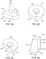
- the parts of the insert 200 will now be described in more detail with particular reference to Figures 6a-d .
- the locator piece 208 comprises generally flat upper and lower surfaces 208a, 208b which are parallel with each other and are connected by a peripheral wall 208c.
- the wall 208c is convex and furthermore is divergently tapered from the upper surface 208a to the lower surface 208b.
- the wall 208c is perpendicular to the upper and lower surfaces 208a, 208b such that the side parts 208e are flat.
- the locator piece 208 also comprises an upstanding stem 208f.
- the outer part 206 of the retainer comprises a circular body having generally flat upper and lower surfaces 206a, 206b, which are parallel with each other and are connected by a peripheral wall 206c which is convergently tapered from the upper surface 206a to the lower surface 206b.
- the outer part 206 of the retainer is a (shallow) frustrum of a cone.
- the outer part 206 also comprises a central through-hole 206d which is sized to snugly receive the upstanding stem 208f of the locator piece 208.
- the inner part 204 of the retainer comprises a body which is shaped similarly to a portion of the outer part 206, such that the inner part 204 comprises generally flat upper and lower surfaces 204a, 204b which are parallel with each other and are connected by a peripheral wall 204c which is convergently tapered from the upper surface 204a to the lower surface 204b.
- the inner part 204 differs from the outer part 206 however in that a segment of the circle (i.e. of the outer part 206) is absent such that the inner part 204 forms a D shape.
- the inner part 204 includes a flat edge 204d which is perpendicular to the upper and lower surfaces 204a, 204b.
- the inner part 204 also comprises a central through-hole 204e which is sized to snugly receive the upstanding 208f stem of the locator piece 208.
- an exemplary segment 202a comprises generally flat upper and lower surfaces 202a1, 202a2 which are connected by a peripheral wall.
- the peripheral wall comprises inner and outer faces 202a3, 202a4 which are connected by two side faces 202a5.
- the outer face 202a4 is shaped to complement the tapered wall 110b of the recess 110 of the stave 100.
- the side faces 202a5 are generally flat and are configured to abut similar side faces of adjacent segments.
- the inner face 202a3 comprises a radius which corresponds to the radii of the peripheral walls 204c, 206c of each of the inner and outer parts 204, 206 of the retainer.
- a lower portion of the inner face 202a3 is provided with a shallow undercut 202a6 which extends to the lower surface 202a2.
- the undercut 202a6 is concavely shaped to complement the convex wall 208c of one of the end parts 208d of the locator piece 208.
- Another portion of the inner face 202a3, which extends between the undercut 202a6 and the upper surface 202a1, is shaped to complement the sloping peripheral walls 204c, 206c of each of the inner and outer parts 204, 206 of the retainer.
- An apex 202a7 separates the lower portion of the inner face 202a3 (which is provided with a shallow undercut 202a6 which extends to the lower surface 202a2) from the other portion of the inner face 202a3 (which extends between the undercut 202a6 and the upper surface 202a1).
- the stave 100 is most conveniently first arranged in a horizontal position for the purpose of installation of the insert 200. That is, the front face 102 will lie in the horizontal plane. It will be understood that in this position the central axis Z of the recess 110 will extend vertically from the front face 102.
- the locator piece 208 is placed upright in the recess 110, such that the lower surface 208b of the locator piece 208 rests on the floor 110a of the recess 110. Initially the locator piece 208 is laterally offset from the four segments 202c-f.
- the locator piece 208 is then slid over the floor 110a of the recess 110, through an opening between the exposed side faces of the endmost segments 202c, 202f, and is rotated into position between the two endmost segments 202c, 202f such that the convex peripheral wall 208c of each one of the end parts 208d of the locator piece 208 is brought into contact with a respective one of the complementary concave undercuts 202c6, 202f6 of the two endmost segments 202c, 202f. In this position the stem 208f of the locator piece 208 is coincident with the central axis Z of the recess 110.
- the locator piece 208 exerts an outward radial force on the two endmost segments 202c, 202f to hold those segments 202c, 202f - and thereby also the two innermost segments 202d, 202e - snugly in place against the wall 110b of the recess 110.
- the inner part 204 of the retainer is briefly positioned over a central (partial) hole which is formed by the four segments 202c-f.
- the inner part 204 is oriented with its upper surface 204a uppermost, the through-hole 204e being coincident with the axis Z of the recess 110.
- the curved, sloping peripheral wall 204c of the inner part 204 overlies the inner faces 202c3-202f3 of the four segments 202c-f and the flat edge 204d of the D-shaped inner part 204 overlies one of the flat side parts 208e of the locator piece 208.
- the inner part 204 of the retainer is then lowered so that the through-hole 204e is passed over the upstanding stem 208f of the locator piece 208.
- the stem 208f serves as a guide for the inner part 204 during its descent between the segments 202c-f.
- the inner part 204 is pressed downwardly (e.g. by hand or with the use of a suitable pressing tool) until the lower surface 204b of the inner part 204 comes into contact with the upper surface 208a of the locator piece 208. In this position a radial force is transmitted from the curved, sloping peripheral wall 204c of the inner part 204 to the curved, sloping inner face 202c3-202f3 of each one of the four segments 202c-f. This causes the four segments 202c-f to be displaced outwardly of the central axis Z so that the outer faces 202c4-202f4 of the four segments 202c-f are pressed against the wall 110b of the recess 110.
- the four segments 202c-f are driven against the wall 110b of the recess 110 and are effectively squeezed between the inner part 204 of the retainer and the wall 110b. In this way the four segments 202c-f are fully secured in the recess 110 by the inner part 204 of the retainer.
- the four segments 202c-f which are secured in the recess 110 by the inner part 204 of the retainer, form a first subset S1 of the set of six segments 202a-f of the insert 200, as will be further explained later herein.
- the two segments 202a, 202b are positioned such that one side face 202a5, 202b5 of each of the two segments 202a, 202b is adjacent to a side face 202a5, 202b5 of the other of the two segments 202a, 202b, while the other side face 202a5, 202b5 is adjacent to a side face 202c5, 202f5 of one of the adjacent segments 202c, 202f.
- the outer face 202a4, 202b4 of the peripheral wall of each of the two segments 202a, 202b is in abutment with the wall 110b of the recess 110.
- the six segments 202a-f fully surround the central axis Z of the recess 110 so as to form a hexagon.
- the outer part 206 of the retainer is briefly positioned over the central hole which is formed by the six segments 202a-f.
- the outer part 206 is oriented with its upper surface 206a uppermost, the through-hole 206d being coincident with the axis Z of the recess 110.
- the curved, sloping peripheral wall 206c of the outer part 206 overlies the inner faces 202a3-202f3 of the six segments 202a-f.
- the outer part 206 of the retainer is then lowered so that the through-hole 206d is passed over the upstanding stem 208f of the locator piece 208.
- the stem 208f serves as a guide for the outer part 206 during its descent between the segments 202a-f.
- the outer part 206 is pressed downwardly (e.g. by hand or with the use of a suitable pressing tool) such that the curved, sloping peripheral wall 206c of the outer part 206 is brought into contact with the curved, sloping inner face 202a3-202f3 of each one of the six segments 202a-f. In this position there exists a small gap (not visible in Figure 7e ) between the lower surface 206b of the outer part 206 and the upper surface 204a of the inner part 204 of the retainer.
- the two segments 202a, 202b are driven against the wall 110b of the recess 110 and are effectively squeezed between the outer part 206 of the retainer and the wall 110b.
- the four segments 202c-f of the first subset S1 of segments are also secured in the recess 110 by the outer part 204 in the same manner. In this way the six segments 202a-f are fully secured in the recess 110 by the outer part 206 of the retainer.
- the two segments 202a, 202b which are secured in the recess 110 by only the outer part 206 of the retainer (i.e. not also by the inner part 204) form a second subset S2 of the set of six segments 202a-f of the insert 200, as will be further explained later herein.
- the wall 110b is convergently tapered between the floor 110a of the recess 110 and the opening of the recess 110 at the front face 102.
- the taper has a wedging effect on the six segments 202a-f which enhances the tightness of the fit of the segments 202a-f in the recess 110.
- the taper in combination with the complementary shaped outer face 202a4-202f4 of each one of the segments 202a-f, provides a strong "dovetail" joint which resists displacement of the segments 202a-f out of the recess 110 in a direction away from the front face 102.
- the mating surfaces that is the respective peripheral walls 204c, 206c of the inner and outer parts 204, 206 of the retainer and the inner faces 202a3-202f3 of the segments 202a-f, are arranged to provide a sufficient degree of friction to prevent slippage between them.
- the required amount of friction may be achieved, for example, by the careful selection of materials and/or treatment of the mating surfaces.
- one or both of the inner and outer parts 204, 206 of the retainer may be secured in position by a suitable fixing, such as a wedge lock washer, for example a Nord-Lock (RTM) washer.
- each one of the six segments 202a-f of the set of inserts is fully secured in the recess 110. More particularly still:
- the segments 202a-f are secured in the recess 110 by friction between the outer surfaces 202a4-202f4 of the segments 202a-f and the surface of the wall 110b of the recess 110.
- This friction arises because the inner and outer parts, 204, 206 of the retainer apply outward radial forces which push the segments 202a-f firmly against the wall 110b.
- the insert 200 may be regarded as a reverse clamp or spreader.
- each of the inner part 204 and the outer part 206 of the retainer may be regarded as a fixing plug.
- connection between the installed insert 200 and the recess 110 is essentially an interference fit (also known as a press fit or a friction fit). That is, the insert 200 is attached to the wall 110b of the recess 110 by friction rather than by any other means of fastening. Accordingly the insert does not rely upon conventional fasteners such as screws, bolts or rivets, which would require threads or holes to be provided in the material of the stave 100. This is highly advantageous, since it is undesirable to provide threads or holes because this can leave a weak section of the stave material in the vicinity of the water-cooling passage which could lead to structural failure and thereby a catastrophic water leak in service.
- conventional fasteners such as screws, bolts or rivets
- insert 200 is attached to the recess 110 in such a way that there is no need for the surface material of the stave 100 to be modified in any way in order to accept the insert 200.
- Each of the inner and outer parts 204, 206 of the retainer can be separated and removed from the inner faces 202a3-202f3 of the segments 202a-f, preferably without destruction of the inner and outer parts 204, 206, so that the insert 200 can be removed in an uninstallation procedure which is essentially the reverse of the installation procedure described herein above. It will therefore be understood that, once installed, the insert 200 is removably attached in the recess 110.
- the installed inserts 200 project or protrude from the front face 102 of the stave 100 and together the inserts 200 form a protective cladding for the front face 102.
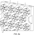
- the use of the cladding with a stave 100 installed in a blast furnace will now be described with particular reference to Figures 8a-d .
- the panel-like stave 100 is installed at an interior wall of the furnace in an upright fashion. It will be understood that only a portion of the stave 100 is shown in the figure.
- the front face 102 faces into the interior of the furnace such that the inserts 200 project from the front face 102 in a substantially horizontal direction.
- burden material While the furnace is being used, burden material will pass downwardly through the interior of the furnace under gravity.
- the burden material may include, for example, condensed vapours, solidified slag, and metal.
- the mass flow rate of the bulk burden material through the furnace is typically around 240 to 1,100 tonnes per hour.
- An outer portion of the burden material will flow over the front face 102 of the stave 100 and between the inserts 200. Some of this burden material will become trapped by the inserts 200. The trapped burden material will be held in contact with the cooled surface of the front face 102 of the stave 100 (as well as with the surfaces of the insert 200) and will adhere to the surface so as to form a protective layer when the burden material is in a reduced, liquid or semi-liquid state.
- the capability of the inserts 200 to trap the burden material is optimised by the specific form of the inserts 200 and their arrangement on the front face 102 of the stave 100, as follows.
- the hexagonal inserts 200 are arranged so as to define channels C between the inserts 200. That is, the exposed portions of the outer faces 202a4-202f4 of the protruding segments 202a-f define walls of the channels C while the front face 102 of the stave 100 forms the bases of the channels C.
- exemplary first and second channels C1, C2 are defined between a first hexagonal insert 200 and two adjacent hexagonal inserts 200, each of these inserts 200 belonging to a first (and uppermost) row of inserts 200 on the stave 100.
- exemplary third and fourth channels C3, C4 are defined between the first hexagonal insert 200 and two other adjacent hexagonal inserts 200, each of these other inserts 200 belonging to a second row of inserts 200 which is below the first row of inserts 200.
- Each one of the first and second channels C1, C2 is bifurcated, one of the branches of the first channel C1 leading into the third channel C3 and one of the branches of the second channel C2 leading into the fourth channel C4.
- the third and fourth channels C3, C4 converge.
- a flow stream F of burden material (not itself shown) will flow through each one of the first and second channels C1, C2 and will emerge at the bifurcation point of each of the channels C1, C2.
- a flow stream F of burden material (not itself shown) will flow through each one of the first and second channels C1, C2 and will emerge at the bifurcation point of each of the channels C1, C2.
- the two streams of the burden material will meet at the point where the third and fourth channels C3, C4 converge.
- the distance between any two of the three points P is about 55 mm, since that is the size of a typical particle contained in the burden material. It will be understood that this spacing can be made to suit any size of burden material specification.
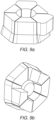
- FIG 8c a set of six segments 202a-f of an insert 200 is newly fitted in a recess 110 of the stave 100 in accordance with the installation procedure described herein above.
- the stave 100 comprises a plurality of similar recesses 110 and inserts 200, as shown in Figure 8a for example).
- the insert 200 shown in Figure 8c represents a new insert 200 at the commencement of the service of the stave 100 in the furnace.
- each one of the segments 202a-f of the inserts 200 comprises silicon carbide.
- this is a very hard-wearing material, the harsh conditions in the furnace are such that the segments 202a-f can be expected to be gradually eroded by the abrasive burden material which passes over and around them. Thus over time the segments 202a-f will be worn down by the burden material.
- the uppermost segments 202a, 202b will be eroded at a faster rate than the other segments 202c-f, since it is the uppermost segments 202a, 202b which will take the brunt of the force of the burden material as it descends through the furnace and down over the stave 100.
- the two uppermost segments 202a, 202b form a second subset S2 of the set of six segments 202a-f which is secured in the recess 110 by only the outer part 206 of the retainer.
- the outer part 206 has been destroyed by the erosive effect of the burden material, there is nothing to hold (what remains of) the two uppermost segments 202a, 202b in the recess 110 and they will therefore be released from the recess 110.
- the two segments 202a, 202b will become entrained in the flowing burden material and will thus be carried away from the recess 110. In time they will be carried some considerable distance from the front face 102 of the stave 100.
- Figure 8d shows the insert 200 in the partly worn condition, at the stage that the outer part 206 has been destroyed and the two uppermost segments 202a, 202b have been released and carried away from the recess 110.
- a portion of the recess 110 is left empty by the vacated segments 202a, 202b. Burden material will tend to flow into the empty portion of the recess 110 and adhere to the floor 110a and wall 110b thereof. In this way the burden material provides a protective layer for the stave 100, even after a portion of the insert 200 has been lost.
- the four segments 202c-f form a first subset S1 of the set of six segments 202a-f which is secured in the recess by the inner part 204 of the retainer (as well as by the outer part 206 at the point of installation of the insert 200).
- a portion of the recess 110 will be left empty by the vacated segments 202c-f. Burden material will tend to flow into the empty portion of the recess 110 and adhere to the floor 110a and wall 110b thereof. In this way the burden material provides a protective layer for the stave 100, even after the entire insert 200 has been lost.
- the invention provides inserts which trap burden material so that the burden material will adhere to the front face of the stave so as to form a protective layer thereon.
- the uppermost segments of each insert which are most prone to wear by the erosive action of the flowing bulk of the burden material, are configured to be released from the recess at a certain stage of wear, so that burden material may take their place in the recess to become adhered to the front face.
- the remaining segments of the insert are also configured to be released from the recess, at a later time, once they too have reached a certain stage of wear.
- the part of the recess that was occupied by those remaining segments then becomes occupied by the burden material which adheres to the front face.
- the recess, when occupied by the burden material is a "stonebox" which protects the stave even after all of the segments of the insert have been worn down and lost.
- the insert provides for a staged release of the segments.
- the stages of wear, at which the segments are released, are predetermined by the relative position (i.e. the distance from the front face of the stave) of the parts of the retainer and the end faces of the segments. In other words, the degree to which the parts of the retainer are recessed between the segments from the end faces of the segments. As the segments are worn down the depth of the recess is reduced, until the parts of the retainer are exposed to the flow of the abrasive burden and are thereby eroded away.
- each of the inserts can accept thermal cycling without releasing from the recess prematurely. This is because the insert is made up of a plurality of segments that can flex independently under thermal stress yet be fixed as a whole for ease of assembly. It will be recalled that there exists a small gap between each pair of the adjacent side faces of the secured segments. It is these gaps which enable the segments to flex independently. Furthermore the gaps encourage material ingress in the form of dust to act as an elastic dividing membrane, thus adding resilience to the effects of thermal cycling. In another embodiment, which is less preferred, the gaps are omitted such that the segments abut one another.
- the inner part 204 of the retainer secures four segments 202c-f (the first subset S1) and the outer part 206 secures six segments 202a-f, such that two segments 202a, 202b (the second subset S2) are secured by only the outer part 206. Accordingly the two segments 202a, 202b are released when the outer part 206 is destroyed, followed by the four segments 202c-f when the inner part 204 is destroyed.
- subsets S1, S2 of the set of segments 202 of the insert 200 may be differently comprised, provided that at least one of the segments 202 which defines the first subset S1 is secured in the recess 110 by the inner part 204 and at least one of the segments 202 which defines the second subset S2 is secured in the recess 110 by only the outer part 206.
- the insert may alternatively be secured using only one retainer part.
- the sole retainer part will then secure all of the segments of the insert.
- an embodiment comprising only one retainer part is not configured to provide a staged release of segments in the manner described herein above. Rather, once the sole retainer part has been destroyed all of the segments will be released from the recess at substantially the same time.
- an insert may comprise more than two retainer parts.
- segments may be released in multiple stages over time according to the number of retainer parts.
- each insert may comprise any number of segments and these may be arranged in any shape.
- an insert may comprise two segments, which may be arranged in a circle.
- the insert may comprise three segments, which may be arranged in a triangle.
- the insert may comprise four segments, which may be arranged in a rectangle, for example a square.
- the insert may comprise five segments, which may be arranged in a pentagon.
- the insert may comprise seven segments, which may be arranged in a heptagon.
- the insert may comprise eight segments, which may be arranged in an octagon. And so on.
- the plurality of inserts may include inserts of dissimilar shape and/or size. Furthermore a set of segments of an insert may include segments of dissimilar shape and/or size.
- the locator piece 208 is omitted. It will be understood that the locator piece 208 is not essential for securing the insert 200 in the recess 110 since it does not serve to fully secure the segments 200a-f to the wall 110b of the recess 110; rather that is the function of the inner and outer parts 204, 206 of the retainer. In this embodiment the undercut (at the lower portion of the inner face of the segment) is also omitted, since the undercut serves only to interface with the locator piece 208.
- the inner and/or outer parts of the retainer are additionally secured by means other than frictional contact with the inner faces of the segments, for example by a screw, bolt or other kind of fastener, or by a weld.
- the upstanding stem of the locator piece includes a thread and one or both of the inner and/or outer parts of the retainer is secured by a nut which engages the thread.
- the wall 110b of the recess 110 is parallel with the central axis Z of the recess 110 and so does not include a taper. This can make machining the recess more straightforward. On the other hand, this embodiment is less preferred because, while the outer faces of the segments 202a-f will be secured against the wall of the recess 110 by the radial forces applied to them, the advantageous wedge effect and strong dovetail joint will be absent.
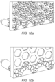
- one or more of the segments of each insert is enlarged (compared to the other segments of the insert), and comprises an outer surface for contact with a similar outer surface of a similarly enlarged segment of another insert when the inserts are installed in a stave.
- This enables the inserts of two adjacent rows in the stave to contact each other to form a continuous ledge which can prevent the passage of burden material between the inserts.
- This may be particularly useful at the bottom of the stave, as shown in Figure 10b , since it is desirable to try to retain as much burden material as possible on the stave before the burden material descends through the furnace below the stave.
Description
- The present invention relates to a stave protection system for a metallurgical furnace, for example a blast furnace.
- A conventional blast furnace comprises several sections and components including a stack, belly, bosh, tuyere, hearth and taphole. The internal shell of the blast furnace may be protected with water-cooled cooling plates, called staves, which protect the shell from overheating during the reduction process taking place within the furnace. Modern staves are typically constructed from copper or copper alloy although other materials may be used, for example steel or cast iron.
- The staves can be susceptible to abrasive wear from the solid raw materials charged into the furnace as they make their descent through the furnace. Coke in particular is very abrasive. In some circumstances the severity of the wear has resulted in the requirement to replace the staves before their planned service life has completed. This is costly due to furnace downtime. It is therefore important to design staves to resist wear so as to prolong service life.
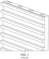
- It is known that wear of the staves is reduced by forming a frozen slag accretion on the front face of the stave during operation. To this end the stave has a machined front face, or hot face, comprising ribs and grooves which hold the accretion onto the stave. A portion of an exemplary copper stave of this type is shown in
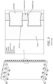
Figure 1 . - A refinement of this concept has been the addition of a front-face protective material or cladding, which is harder than the copper base material but which still allows a protective accretion layer to form by freezing on the face. This has been achieved using a combination of silicon carbide and graphite bricks, as illustrated in
Figure 2 which shows a copper stave and a cross-section thereof. -
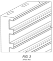
WO2009/147192 describes a stave having a front face comprising ribs and grooves which form anchorage means for anchoring a refractory brick lining, a refractory guniting or a process generated accretion layer to the face. Metal inserts are provided in the grooves, as is illustrated schematically inFigure 3 . The metal inserts cover the sidewalls of the ribs to protect the ribs from erosion. Possible problems with this solution however are that the metal inserts may be prone to distortion and/or buckling, and by using a less conductive material than that of the stave body (when copper) there is a reduced thermal performance of the stave which can impact the freezing of a protective accretion layer. Furthermore,US 4 528 672 A discloses a protected stave with refractory elements. - Thus the existing solutions for reducing the rate of stave wear include:
- i) installing a refractory/ceramic wear lining in or in front of the stave;
- ii) installing ledges at the front face of the stave to promote thicker accretion build-up; and
- iii) installing cladding within the machined shapes at the front face.
- According to an aspect of the invention, there is provided a stave protection system for a metallurgical furnace, comprising: a stave comprising a plurality of recesses arranged on a front face of the stave; and a plurality of inserts each being received by a respective one of the recesses, the inserts so received projecting from the front face of the stave such that, in use, furnace burden material is trapped by the inserts so as to provide a protective layer of the burden material on the front face of the stave, wherein each insert comprises a set of segments and a retainer which forces the segments against a surface of the respective recess, such that the segments are secured in the recess by frictional contact with the surface of the recess.
- As will be described in more detail later herein, the inserts provide a cladding for the front face (or hot face) of the stave which encourages a protective layer of furnace burden material to form on the front face. The inserts are attached to the recesses by means of friction only, thereby avoiding any need to modify the surface of the front face in order to attach the inserts.
- As used herein, "burden material" refers to one or both of (i) iron-bearing materials in the blast furnace, for example iron-ore or iron-ore pellets, and (ii) blast furnace slag, i.e. slag which is formed when iron-ore or iron pellets, coke and a flux (e.g. limestone or dolomite) are melted together in the blast furnace and then solidified.
- The retainer may comprise an inner part and an outer part; at least one of the segments, defining a first subset of the set of segments, is secured in the recess by the inner part; at least one of the segments, defining a second subset of the set of segments, is secured in the recess by only the outer part, so that in use: removal of the outer part of the retainer, by an erosive effect of the burden material thereon, releases the second subset such that burden material may occupy that portion of the recess which is vacated by the second subset; and removal of the inner part of the retainer, by an erosive effect of the burden material thereon, releases the first subset such that burden material may occupy that portion of the recess which is vacated by the first subset.
- The stave protection system may comprise a locator element which is configured to locate the first subset of the set of segments in the recess. The locator element may be configured to support the inner and outer parts of the retainer.
- Each one of the recesses may have a hexagonal shape and the set of segments may comprise six segments which are arranged in a hexagon to complement the respective recess. The first subset of the set of segments may comprise four segments and the second subset of the set of segments may comprise two segments.
- The segments and/or the retainer of each insert may comprise an abrasion resistant refractory material. The abrasion resistant refractory material may comprise silicon carbide or alumina.
- The segments and/or the retainer of each insert may comprise a metallic material. The metallic material may comprise copper, copper alloy, steel, or cast iron.
- Each one of the segments may be separated from an adjacent segment by a gap.
- According to another aspect of the invention, there is provided a metallurgical furnace stave body, comprising: a front face, a rear face, and edges which connect the front and rear faces; at least one cooling passage which extends through the body; and a plurality of discrete recesses arranged on the front face, at least one of the recesses being surrounded by a portion of the front face, so that in use furnace burden material is received and retained by the recesses to provide a protective layer of the burden material on the front face,
wherein each recess comprises a floor and a wall and an opening of the recess at the front face, wherein the wall of each recess has a taper such as to be convergent between the floor and the opening of the recess at the front face. - The recesses may be formed by machining the front face. The stave body may be a casting.
- The stave body may be constructed from copper, copper alloy, steel, or cast iron.
- The recesses may have a hexagonal shape.
- One or more of the recesses may be configured to receive a protruding insert for trapping furnace burden material.
- The recesses may be arranged in a uniform pattern. The uniform pattern may comprise an array having rows and columns. The stave body may have the same bending stiffness in a first direction and a second direction which is perpendicular to the first direction.
- Preferably the recesses have a hexagonal shape and are arranged in an array having rows and columns, thereby providing a honeycomb pattern of the recesses. The honeycomb pattern endows the stave body with an inherent stiffness and the stave body will tend to have more uniform stiffness than a conventional grooved stave of the kind shown in
Figure 1 . - Embodiments will now be described, by way of example, with reference to the accompanying figures in which:
-
Figure 1 shows a portion of a conventional copper stave for a furnace; -
Figure 2 shows a conventional copper stave comprising silicon carbide and graphite bricks; -
Figure 3 shows a portion of a conventional copper stave comprising metal inserts; -
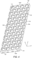
Figure 4 shows a stave according to an embodiment of the invention; -
Figure 5a shows a set of inserts installed in the stave ofFigure 4 andFigure 5b shows a cutaway view of one of the installed inserts; -
Figures 6a-d show parts of the inserts; -
Figures 7a-e show the installation of the inserts in the stave; -
Figures 8a-d relate to use of the stave with the inserts installed; and -
Figures 9a-10b show staves and sets of inserts according to other embodiments of the invention. - Referring to
Figure 4 , a rectangular cooling plate orstave 100 comprises a front face (or hot face) 102, arear face 104, andedges 106a-d. The stave 100 is intended to be one of a plurality of similar staves for use in a blast furnace. - In this exemplary embodiment the stave 100 is constructed from copper alloy. Alternative materials include, but are not limited to, copper, steel, and cast iron.
- In this embodiment the stave has a length of about 1.5 m, a width of about 1.0 m, and a thickness of about 120 mm.
- The interior of the stave 100 comprises water-cooling passages (not shown). The stave 100 body is otherwise generally solid.
- A plurality of
recesses 110 is formed in thefront face 102 of the stave 100. Therecesses 110 are formed by machining. Alternatively therecesses 110 may be formed by casting. - Each one of the
recesses 110 comprises a base orfloor 110a and awall 110b. Thefloor 110a is flat such as to be parallel with thefront face 102 of the stave 100. In this embodiment each of therecesses 110 has a width of about 165 mm at the opening and a depth (from the opening to thefloor 110a) of about 45 mm. In other embodiments the depth may be about 35 to 55 mm. - The
wall 110b of eachrecess 110 has a taper such as to be convergent between thefloor 110a and the opening of therecess 110 at thefront face 102. Accordingly the cross-sectional area of therecess 110 is greater at thefloor 110a than at the opening. - The
recesses 110 are discrete recesses. That is, each one of therecesses 110 is separated from all of theother recesses 110 by the material of the body of the stave 100. Thus therecesses 110 may be regarded as pockets in the stave 100, each of the pockets being isolated from the rest of the pockets. - Also a majority of the
recesses 110 are entirely surrounded at their openings by a portion of the front face 102 (the few exceptions being thoserecesses 110 which are located at the edges of the stave 100). In other words, the majority of therecesses 110 are each bounded and defined by an endless perimeter. - Furthermore each of the
recesses 110 extends across only a small portion or fraction of thefront face 102 of the stave 100; none of therecesses 110 extends across the entirety of the length or width of thefront face 102. - In this embodiment the
recesses 110 are arranged in a pattern, more particularly a uniform pattern, more particularly still an array. As a result of the uniform spacing of therecesses 110 the rectangular stave has the same bending stiffness in the longitudinal (lengthwise Y) direction as the transverse (widthwise X) direction. - The array of
recesses 110 comprises 15 (horizontal) rows and four (vertical) columns. Alternatively the array may comprise a different number of rows and columns, for example as many as 20 rows and 5 columns. - In this embodiment the recesses are hexagonal (in frontal view) such as to form a honeycomb pattern. As will be understood from the following description, one or more of the
recesses 110 may take other shapes, including but not limited to a circle, a triangle, a rectangle including a square, a pentagon, a heptagon, or an octagon. - Turning now to
Figures 5a and5b , inserts 200 are installed in therecesses 110 of the stave 100. In combination the stave 100 and theinserts 200 comprise a stave protection system. - Each of the
inserts 200 comprises a plurality of component pieces or segments, there being sixsegments 202a-f perinsert 200 in this embodiment. Thesegments 202a-f are arranged around a central axis Z of therespective recess 110, the central axis Z being perpendicular to thefront face 102 of the stave 100. In this embodiment each of thesegments 202a-f comprises silicon carbide. Alternatively thesegments 202a-f may comprise cast iron or steel. - Each
insert 200 further comprises a retainer which in this embodiment includes aninner part 204 and anouter part 206. In this embodiment each of theinner part 204 and theouter part 206 of the retainer comprises steel. Alternatively theinner part 204 and theouter part 206 may comprise silicon carbide. - In this embodiment the
insert 200 also comprises alocator piece 208. Thelocator piece 208 comprises steel. Alternatively thelocator piece 208 may comprise silicon carbide. - Thus each of the inserts comprises a number of component parts and may be regarded as an assembly of those parts. The parts of the
insert 200 will now be described in more detail with particular reference toFigures 6a-d . - Referring firstly to
Figure 6a , thelocator piece 208 comprises generally flat upper andlower surfaces peripheral wall 208c. Atend parts 208d of thelocator piece 208 thewall 208c is convex and furthermore is divergently tapered from theupper surface 208a to thelower surface 208b. Atside parts 208e of thelocator piece 208 thewall 208c is perpendicular to the upper andlower surfaces side parts 208e are flat. Thelocator piece 208 also comprises anupstanding stem 208f. - Referring now to
Figure 6b , theouter part 206 of the retainer comprises a circular body having generally flat upper andlower surfaces peripheral wall 206c which is convergently tapered from theupper surface 206a to thelower surface 206b. In other words, theouter part 206 of the retainer is a (shallow) frustrum of a cone. Theouter part 206 also comprises a central through-hole 206d which is sized to snugly receive theupstanding stem 208f of thelocator piece 208. - Referring now to
Figure 6c , theinner part 204 of the retainer comprises a body which is shaped similarly to a portion of theouter part 206, such that theinner part 204 comprises generally flat upper andlower surfaces peripheral wall 204c which is convergently tapered from theupper surface 204a to thelower surface 204b. Theinner part 204 differs from theouter part 206 however in that a segment of the circle (i.e. of the outer part 206) is absent such that theinner part 204 forms a D shape. Accordingly theinner part 204 includes aflat edge 204d which is perpendicular to the upper andlower surfaces inner part 204 also comprises a central through-hole 204e which is sized to snugly receive the upstanding 208f stem of thelocator piece 208. - Referring now to
Figure 6d , anexemplary segment 202a comprises generally flat upper and lower surfaces 202a1, 202a2 which are connected by a peripheral wall. The peripheral wall comprises inner and outer faces 202a3, 202a4 which are connected by two side faces 202a5. The outer face 202a4 is shaped to complement thetapered wall 110b of therecess 110 of the stave 100. The side faces 202a5 are generally flat and are configured to abut similar side faces of adjacent segments. The inner face 202a3 comprises a radius which corresponds to the radii of theperipheral walls outer parts - A lower portion of the inner face 202a3 is provided with a shallow undercut 202a6 which extends to the lower surface 202a2. The undercut 202a6 is concavely shaped to complement the
convex wall 208c of one of theend parts 208d of thelocator piece 208. Another portion of the inner face 202a3, which extends between the undercut 202a6 and the upper surface 202a1, is shaped to complement the slopingperipheral walls outer parts - The installation of the sets of
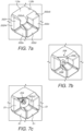
inserts 200 in therespective recesses 110 will now be explained with particular reference toFigures 7a-e . For brevity, the operation will be presented in terms of only one of theinserts 200 in one of therecesses 110; however it will be understood that the principle of installation will be the same for all of theinserts 200. - The stave 100 is most conveniently first arranged in a horizontal position for the purpose of installation of the
insert 200. That is, thefront face 102 will lie in the horizontal plane. It will be understood that in this position the central axis Z of therecess 110 will extend vertically from thefront face 102. - Referring firstly to
Figure 7a , in a first stage of the installation procedure foursegments 202c-f of the set of sixsegments 202a-f of theinsert 200 are placed upright in therecess 110 of the stave 100, such that the lower surface 202c2-202f2) of each of thesegments 202c-f rests on thefloor 110a of therecess 110. Thesegments 202c-f are brought together such that their side faces 202c5-202f5 are adjacent to one another. The outer face 202c4-202f4 of the peripheral wall of each of the foursegments 202c-f is in abutment with thewall 110b of therecess 110. The foursegments 202c-f partially surround the central axis Z of therecess 110. - Referring now to
Figure 7b , in a second stage of the installation procedure thelocator piece 208 is placed upright in therecess 110, such that thelower surface 208b of thelocator piece 208 rests on thefloor 110a of therecess 110. Initially thelocator piece 208 is laterally offset from the foursegments 202c-f. Thelocator piece 208 is then slid over thefloor 110a of therecess 110, through an opening between the exposed side faces of theendmost segments endmost segments peripheral wall 208c of each one of theend parts 208d of thelocator piece 208 is brought into contact with a respective one of the complementary concave undercuts 202c6, 202f6 of the twoendmost segments stem 208f of thelocator piece 208 is coincident with the central axis Z of therecess 110. - Once rotated into position, the
locator piece 208 exerts an outward radial force on the twoendmost segments segments innermost segments wall 110b of therecess 110. - At this stage the four
segments 202c-f are sufficiently secured that they are prevented from moving laterally within therecess 110. - Referring now to
Figure 7c , in a third stage of the installation procedure theinner part 204 of the retainer is briefly positioned over a central (partial) hole which is formed by the foursegments 202c-f. In this initial position theinner part 204 is oriented with itsupper surface 204a uppermost, the through-hole 204e being coincident with the axis Z of therecess 110. The curved, slopingperipheral wall 204c of theinner part 204 overlies the inner faces 202c3-202f3 of the foursegments 202c-f and theflat edge 204d of the D-shapedinner part 204 overlies one of theflat side parts 208e of thelocator piece 208. Theinner part 204 of the retainer is then lowered so that the through-hole 204e is passed over theupstanding stem 208f of thelocator piece 208. Thestem 208f serves as a guide for theinner part 204 during its descent between thesegments 202c-f. - The
inner part 204 is pressed downwardly (e.g. by hand or with the use of a suitable pressing tool) until thelower surface 204b of theinner part 204 comes into contact with theupper surface 208a of thelocator piece 208. In this position a radial force is transmitted from the curved, slopingperipheral wall 204c of theinner part 204 to the curved, sloping inner face 202c3-202f3 of each one of the foursegments 202c-f. This causes the foursegments 202c-f to be displaced outwardly of the central axis Z so that the outer faces 202c4-202f4 of the foursegments 202c-f are pressed against thewall 110b of therecess 110. That is, the foursegments 202c-f are driven against thewall 110b of therecess 110 and are effectively squeezed between theinner part 204 of the retainer and thewall 110b. In this way the foursegments 202c-f are fully secured in therecess 110 by theinner part 204 of the retainer. - The four
segments 202c-f, which are secured in therecess 110 by theinner part 204 of the retainer, form a first subset S1 of the set of sixsegments 202a-f of theinsert 200, as will be further explained later herein. - Referring now to
Figure 7d , in a fourth stage of the installation procedure the remaining twosegments segments 202a-f are placed upright in therecess 110, such that the lower surface 202a2, 202b2 of each of thesegments floor 110a of therecess 110. The twosegments segments segments adjacent segments segments wall 110b of therecess 110. The sixsegments 202a-f fully surround the central axis Z of therecess 110 so as to form a hexagon. - Referring now to
Figure 7e , in a fifth stage of the installation procedure theouter part 206 of the retainer is briefly positioned over the central hole which is formed by the sixsegments 202a-f. In this initial position theouter part 206 is oriented with itsupper surface 206a uppermost, the through-hole 206d being coincident with the axis Z of therecess 110. The curved, slopingperipheral wall 206c of theouter part 206 overlies the inner faces 202a3-202f3 of the sixsegments 202a-f. Theouter part 206 of the retainer is then lowered so that the through-hole 206d is passed over theupstanding stem 208f of thelocator piece 208. Thestem 208f serves as a guide for theouter part 206 during its descent between thesegments 202a-f. - The
outer part 206 is pressed downwardly (e.g. by hand or with the use of a suitable pressing tool) such that the curved, slopingperipheral wall 206c of theouter part 206 is brought into contact with the curved, sloping inner face 202a3-202f3 of each one of the sixsegments 202a-f. In this position there exists a small gap (not visible inFigure 7e ) between thelower surface 206b of theouter part 206 and theupper surface 204a of theinner part 204 of the retainer. - Also in this position a radial force is transmitted from the curved, sloping
peripheral wall 206c of theouter part 206 to the curved, sloping inner face 202a3-202f3 of each one of the sixsegments 202a-f. This causes the twosegments segments 202c-f of the first subset S1 of segments, are not secured in therecess 110 by the inner part 204) to be displaced outwardly of the central axis Z so that the outer faces 202a4, 202b4 of the twosegments wall 110b of therecess 110. That is, the twosegments wall 110b of therecess 110 and are effectively squeezed between theouter part 206 of the retainer and thewall 110b. It will be understood that the foursegments 202c-f of the first subset S1 of segments are also secured in therecess 110 by theouter part 204 in the same manner. In this way the sixsegments 202a-f are fully secured in therecess 110 by theouter part 206 of the retainer. - The two
segments recess 110 by only theouter part 206 of the retainer (i.e. not also by the inner part 204) form a second subset S2 of the set of sixsegments 202a-f of theinsert 200, as will be further explained later herein. - As will be further explained later herein, in this embodiment there exists a small gap between each pair of the adjacent side faces 202a5-202f5 of the secured
segments 202a-f. - It will be recalled that the
wall 110b is convergently tapered between thefloor 110a of therecess 110 and the opening of therecess 110 at thefront face 102. The taper has a wedging effect on the sixsegments 202a-f which enhances the tightness of the fit of thesegments 202a-f in therecess 110. Also the taper, in combination with the complementary shaped outer face 202a4-202f4 of each one of thesegments 202a-f, provides a strong "dovetail" joint which resists displacement of thesegments 202a-f out of therecess 110 in a direction away from thefront face 102. - The radial forces, which are applied by the inner and
outer parts segments 202a-f from thewall 110b of therecess 110. It is important that the reaction forces do not cause the slopingperipheral walls outer parts segments 202a-f, since this would tend to relax the outer faces 202a4-202f4 of thesegments 202a-f away from thewall 110b and thereby compromise the security of thesegments 202a-f in therecess 110. - For this reason the mating surfaces, that is the respective
peripheral walls outer parts segments 202a-f, are arranged to provide a sufficient degree of friction to prevent slippage between them. The required amount of friction may be achieved, for example, by the careful selection of materials and/or treatment of the mating surfaces. Alternatively one or both of the inner andouter parts - Thus at the completion of the installation procedure the
insert 200 is fully secured in therecess 110 of the stave 100. More particularly, each one of the sixsegments 202a-f of the set of inserts is fully secured in therecess 110. More particularly still: - i) all six
segments 202a-f of the set of segments are secured by theouter part 206 of the retainer; - ii) four
segments 202c-f, which form a first subset S1 of the set of segments, are additionally secured by theinner part 204 of the retainer; and - iii) two
segments outer part 206 of the retainer. - The
segments 202a-f are secured in therecess 110 by friction between the outer surfaces 202a4-202f4 of thesegments 202a-f and the surface of thewall 110b of therecess 110. This friction arises because the inner and outer parts, 204, 206 of the retainer apply outward radial forces which push thesegments 202a-f firmly against thewall 110b. Thus theinsert 200 may be regarded as a reverse clamp or spreader. In view of the manner in which theinner part 204 and theouter part 206 of the retainer are pushed into the central hole which is formed by the sixsegments 202a-f, each of theinner part 204 and theouter part 206 may be regarded as a fixing plug. - The connection between the installed
insert 200 and therecess 110 is essentially an interference fit (also known as a press fit or a friction fit). That is, theinsert 200 is attached to thewall 110b of therecess 110 by friction rather than by any other means of fastening. Accordingly the insert does not rely upon conventional fasteners such as screws, bolts or rivets, which would require threads or holes to be provided in the material of the stave 100. This is highly advantageous, since it is undesirable to provide threads or holes because this can leave a weak section of the stave material in the vicinity of the water-cooling passage which could lead to structural failure and thereby a catastrophic water leak in service. - Neither does installation of the
insert 200 involve welding or brazing. Thus it will be understood that theinsert 200 is attached to therecess 110 in such a way that there is no need for the surface material of the stave 100 to be modified in any way in order to accept theinsert 200. - Each of the inner and
outer parts segments 202a-f, preferably without destruction of the inner andouter parts insert 200 can be removed in an uninstallation procedure which is essentially the reverse of the installation procedure described herein above. It will therefore be understood that, once installed, theinsert 200 is removably attached in therecess 110. - The installed inserts 200 project or protrude from the
front face 102 of the stave 100 and together theinserts 200 form a protective cladding for thefront face 102. The use of the cladding with a stave 100 installed in a blast furnace will now be described with particular reference toFigures 8a-d . - Referring firstly to
Figure 8a , the panel-like stave 100 is installed at an interior wall of the furnace in an upright fashion. It will be understood that only a portion of the stave 100 is shown in the figure. Thefront face 102 faces into the interior of the furnace such that theinserts 200 project from thefront face 102 in a substantially horizontal direction. - While the furnace is being used, burden material will pass downwardly through the interior of the furnace under gravity. The burden material may include, for example, condensed vapours, solidified slag, and metal. The mass flow rate of the bulk burden material through the furnace is typically around 240 to 1,100 tonnes per hour.
- An outer portion of the burden material will flow over the
front face 102 of the stave 100 and between theinserts 200. Some of this burden material will become trapped by theinserts 200. The trapped burden material will be held in contact with the cooled surface of thefront face 102 of the stave 100 (as well as with the surfaces of the insert 200) and will adhere to the surface so as to form a protective layer when the burden material is in a reduced, liquid or semi-liquid state. - In the described embodiment, the capability of the
inserts 200 to trap the burden material is optimised by the specific form of theinserts 200 and their arrangement on thefront face 102 of the stave 100, as follows. - Referring again to
Figure 8a , thehexagonal inserts 200 are arranged so as to define channels C between theinserts 200. That is, the exposed portions of the outer faces 202a4-202f4 of the protrudingsegments 202a-f define walls of the channels C while thefront face 102 of the stave 100 forms the bases of the channels C. - Referring also now to
Figure 8b , exemplary first and second channels C1, C2 are defined between a firsthexagonal insert 200 and two adjacenthexagonal inserts 200, each of theseinserts 200 belonging to a first (and uppermost) row ofinserts 200 on the stave 100. Furthermore exemplary third and fourth channels C3, C4 are defined between the firsthexagonal insert 200 and two other adjacenthexagonal inserts 200, each of theseother inserts 200 belonging to a second row ofinserts 200 which is below the first row ofinserts 200. Each one of the first and second channels C1, C2 is bifurcated, one of the branches of the first channel C1 leading into the third channel C3 and one of the branches of the second channel C2 leading into the fourth channel C4. Furthermore the third and fourth channels C3, C4 converge. - As is indicated by the arrows in
Figure 8b , a flow stream F of burden material (not itself shown) will flow through each one of the first and second channels C1, C2 and will emerge at the bifurcation point of each of the channels C1, C2. Around half of the burden material from the first channel C1 will flow into the third channel C3 and around half of the burden material from the second channel C1 will flow into the fourth channel C4. The two streams of the burden material will meet at the point where the third and fourth channels C3, C4 converge. - It will be seen that at this point of convergence there is defined a zone T of the
front face 102 of the stave 100 which is bounded by three proximate points P of the hexagonal inserts 200. It will be understood that the points P are two-dimensional representations of vertices of the hexagonal inserts 200. The zone T is effectively a "bottleneck" for the flow of burden material, which tends to be trapped in the zone T between the three points P of the hexagonal inserts 200. Thus the arrangement of thehexagonal inserts 200 provides a highly effective "three-point anchor" for retaining the burden material which is directed into the zone T by the channels C1-C4. - In this exemplary embodiment, the distance between any two of the three points P is about 55 mm, since that is the size of a typical particle contained in the burden material. It will be understood that this spacing can be made to suit any size of burden material specification.
- The use of the cladding will now be further described with particular reference to
Figures 8c and 8d . - Referring firstly to
Figure 8c , a set of sixsegments 202a-f of aninsert 200 is newly fitted in arecess 110 of the stave 100 in accordance with the installation procedure described herein above. (While only onerecess 110 and oneinsert 200 is shown, it will be understood that the stave 100 comprises a plurality ofsimilar recesses 110 and inserts 200, as shown inFigure 8a for example). Thus theinsert 200 shown inFigure 8c represents anew insert 200 at the commencement of the service of the stave 100 in the furnace. - It will be recalled that, in the described embodiment, each one of the
segments 202a-f of theinserts 200 comprises silicon carbide. Although this is a very hard-wearing material, the harsh conditions in the furnace are such that thesegments 202a-f can be expected to be gradually eroded by the abrasive burden material which passes over and around them. Thus over time thesegments 202a-f will be worn down by the burden material. Furthermore it is likely that theuppermost segments other segments 202c-f, since it is theuppermost segments - Eventually the
segments 202a-f - especially theuppermost segments outer part 206 of the retainer. At this stage theouter part 206 will also be exposed to the abrasive effect of the flowing burden material. Over time, theouter part 206 will inevitably also be worn away. - It will be recalled that the two
uppermost segments segments 202a-f which is secured in therecess 110 by only theouter part 206 of the retainer. Once theouter part 206 has been destroyed by the erosive effect of the burden material, there is nothing to hold (what remains of) the twouppermost segments recess 110 and they will therefore be released from therecess 110. The twosegments recess 110. In time they will be carried some considerable distance from thefront face 102 of the stave 100. -
Figure 8d shows theinsert 200 in the partly worn condition, at the stage that theouter part 206 has been destroyed and the twouppermost segments recess 110. As can be seen, a portion of therecess 110 is left empty by the vacatedsegments recess 110 and adhere to thefloor 110a andwall 110b thereof. In this way the burden material provides a protective layer for the stave 100, even after a portion of theinsert 200 has been lost. - Still referring to
Figure 8d , the remaining foursegments 202c-f will continue to be exposed to the erosive effect of the burden material and will eventually be worn down to the level of theinner part 204 of the retainer. At this stage theinner part 204 will also be exposed to the abrasive effect of the flowing burden material. Over time, theinner part 204 will inevitably also be worn away. - It will be recalled that the four
segments 202c-f form a first subset S1 of the set of sixsegments 202a-f which is secured in the recess by theinner part 204 of the retainer (as well as by theouter part 206 at the point of installation of the insert 200). Once theinner part 204 has been destroyed by the erosive effect of the burden material (theouter part 206 of the retainer already having been destroyed), there is nothing to hold (what remains of) the foursegments 202c-f in therecess 110 and they will therefore be released from therecess 110 along with thelocator piece 208. The foursegments 202c-f and thelocator piece 208 will become entrained in the flowing burden material and will thus be carried away from therecess 110. In time they will be carried some considerable distance from thefront face 102 of the stave 100. - A portion of the
recess 110 will be left empty by the vacatedsegments 202c-f. Burden material will tend to flow into the empty portion of therecess 110 and adhere to thefloor 110a andwall 110b thereof. In this way the burden material provides a protective layer for the stave 100, even after theentire insert 200 has been lost. - Thus the invention according to the described embodiment provides inserts which trap burden material so that the burden material will adhere to the front face of the stave so as to form a protective layer thereon. The uppermost segments of each insert, which are most prone to wear by the erosive action of the flowing bulk of the burden material, are configured to be released from the recess at a certain stage of wear, so that burden material may take their place in the recess to become adhered to the front face. The remaining segments of the insert are also configured to be released from the recess, at a later time, once they too have reached a certain stage of wear. The part of the recess that was occupied by those remaining segments then becomes occupied by the burden material which adheres to the front face. The recess, when occupied by the burden material, is a "stonebox" which protects the stave even after all of the segments of the insert have been worn down and lost.
- The insert provides for a staged release of the segments. The stages of wear, at which the segments are released, are predetermined by the relative position (i.e. the distance from the front face of the stave) of the parts of the retainer and the end faces of the segments. In other words, the degree to which the parts of the retainer are recessed between the segments from the end faces of the segments. As the segments are worn down the depth of the recess is reduced, until the parts of the retainer are exposed to the flow of the abrasive burden and are thereby eroded away.
- Each of the inserts can accept thermal cycling without releasing from the recess prematurely. This is because the insert is made up of a plurality of segments that can flex independently under thermal stress yet be fixed as a whole for ease of assembly. It will be recalled that there exists a small gap between each pair of the adjacent side faces of the secured segments. It is these gaps which enable the segments to flex independently. Furthermore the gaps encourage material ingress in the form of dust to act as an elastic dividing membrane, thus adding resilience to the effects of thermal cycling. In another embodiment, which is less preferred, the gaps are omitted such that the segments abut one another.
- In the described embodiment, the
inner part 204 of the retainer secures foursegments 202c-f (the first subset S1) and theouter part 206 secures sixsegments 202a-f, such that twosegments outer part 206. Accordingly the twosegments outer part 206 is destroyed, followed by the foursegments 202c-f when theinner part 204 is destroyed. However it will be understood that the subsets S1, S2 of the set of segments 202 of theinsert 200 may be differently comprised, provided that at least one of the segments 202 which defines the first subset S1 is secured in therecess 110 by theinner part 204 and at least one of the segments 202 which defines the second subset S2 is secured in therecess 110 by only theouter part 206. - On the other hand, while the described embodiment comprises both an inner part and an outer part of the retainer, it will be understood that the insert may alternatively be secured using only one retainer part. The sole retainer part will then secure all of the segments of the insert. Of course an embodiment comprising only one retainer part is not configured to provide a staged release of segments in the manner described herein above. Rather, once the sole retainer part has been destroyed all of the segments will be released from the recess at substantially the same time.
- Alternatively an insert may comprise more than two retainer parts. In such an embodiment, segments may be released in multiple stages over time according to the number of retainer parts.
- While the described embodiment relates to inserts each comprising six segments which are arranged in a hexagon, it will be understood that each insert may comprise any number of segments and these may be arranged in any shape. For example, an insert may comprise two segments, which may be arranged in a circle. Alternatively the insert may comprise three segments, which may be arranged in a triangle. Alternatively the insert may comprise four segments, which may be arranged in a rectangle, for example a square. Alternatively the insert may comprise five segments, which may be arranged in a pentagon. Alternatively the insert may comprise seven segments, which may be arranged in a heptagon. Alternatively the insert may comprise eight segments, which may be arranged in an octagon. And so on. It will be apparent to the skilled person that the number of segments may be varied and the segments may be arranged in a polygon of any form. All of these shapes and arrangements are within the scope of the claimed invention. Of course the recesses in the front face of the stave may be shaped to correspond to the shape of the inserts.
- The plurality of inserts may include inserts of dissimilar shape and/or size. Furthermore a set of segments of an insert may include segments of dissimilar shape and/or size.
- In an embodiment, the
locator piece 208 is omitted. It will be understood that thelocator piece 208 is not essential for securing theinsert 200 in therecess 110 since it does not serve to fully secure the segments 200a-f to thewall 110b of therecess 110; rather that is the function of the inner andouter parts locator piece 208. - In an embodiment, the inner and/or outer parts of the retainer are additionally secured by means other than frictional contact with the inner faces of the segments, for example by a screw, bolt or other kind of fastener, or by a weld. In one such embodiment, the upstanding stem of the locator piece includes a thread and one or both of the inner and/or outer parts of the retainer is secured by a nut which engages the thread.
- In an embodiment, the
wall 110b of therecess 110 is parallel with the central axis Z of therecess 110 and so does not include a taper. This can make machining the recess more straightforward. On the other hand, this embodiment is less preferred because, while the outer faces of thesegments 202a-f will be secured against the wall of therecess 110 by the radial forces applied to them, the advantageous wedge effect and strong dovetail joint will be absent. - Referring to
Figures 9a-10b , in an embodiment one or more of the segments of each insert is enlarged (compared to the other segments of the insert), and comprises an outer surface for contact with a similar outer surface of a similarly enlarged segment of another insert when the inserts are installed in a stave. This enables the inserts of two adjacent rows in the stave to contact each other to form a continuous ledge which can prevent the passage of burden material between the inserts. This may be particularly useful at the bottom of the stave, as shown inFigure 10b , since it is desirable to try to retain as much burden material as possible on the stave before the burden material descends through the furnace below the stave.
Claims (15)
- A stave protection system for a metallurgical furnace, comprising:a stave (100) comprising a plurality of recesses (110) arranged on a front face (102) of the stave (100); anda plurality of inserts (200) each being received by a respective one of the recesses (110), the inserts (200) so received projecting from the front face (102) of the stave (100) such that, in use, furnace burden material is trapped by the inserts (200) so as to provide a protective layer of the burden material on the front face (102) of the stave (100),wherein each insert (200) comprises a set of segments and a retainer which forces the segments against a surface of the respective recess (110), such that the segments are secured in the recess (110) by frictional contact with the surface of the recess (110).
- A stave protection system according to claim 1, wherein:the retainer comprises an inner part (204) and an outer part (206);at least one of the segments, defining a first subset (S1) of the set of segments, is secured in the recess (110) by the inner part (204);at least one of the segments, defining a second subset (S2) of the set of segments, is secured in the recess (110) by only the outer part (206),so that in use:removal of the outer part (206) of the retainer, by an erosive effect of the burden material thereon, releases the second subset (S2) such that burden material may occupy that portion of the recess which is vacated by the second subset (S2); andremoval of the inner part (204) of the retainer, by an erosive effect of the burden material thereon, releases the first subset (S1) such that burden material may occupy that portion of the recess (110) which is vacated by the first subset (S1).
- A stave protection system according to claim 2, comprising a locator element (208) which is configured to locate the first subset (S1) of the set of segments in the recess (110).
- A stave protection system according to claim 3, wherein the locator element (208) is configured to support the inner and outer parts (204,206) of the retainer.
- A stave protection system according to any preceding claim, wherein each one of the recesses (110) has a hexagonal shape and the set of segments comprises six segments (202a-f) which are arranged in a hexagon to complement the respective recess (110).
- A stave protection system according to claim 5, wherein the first subset (S1) of the set of segments comprises four segments (202c-f) and the second subset (S2) of the set of segments comprises two segments (202a-b).
- A stave protection system according to any preceding claim, wherein the segments and/or the retainer of each insert (200) comprise an abrasion resistant refractory material.
- A stave protection system according to claim 7, wherein the abrasion resistant refractory material comprises silicon carbide or alumina.
- A stave protection system according to any one of claims 1 to 6, wherein the segments and/or the retainer of each insert (200) comprises a metallic material.
- A stave protection system according to claim 9, wherein the metallic material comprises copper, copper alloy, steel, or cast iron.
- A stave protection system according to any preceding claim, wherein each one of the segments is separated from an adjacent segment by a gap.
- A metallurgical furnace stave body (100), comprising:a front face (102), a rear face (104), and edges (106a-d) which connect the front and rear faces (102, 104);at least one cooling passage which extends through the body (100); anda plurality of discrete recesses (110) arranged on the front face (102), at least one of the recesses (110) being surrounded by a portion of the front face (102), so that in use furnace burden material is received and retained by the recesses (110) to provide a protective layer of the burden material on the front face (102),each recess (110) comprising a floor (110a) and a wall (110b) and an opening of the recess (110) at the front face (102), wherein the wall (110b) of each recess (110) has a taper such as to be convergent between the floor (110a) and the opening of the recess (110) at the front face (102).
- A metallurgical furnace stave body according to claim 12, wherein the stave body (100) is constructed from copper, copper alloy, steel, or cast iron.
- A metallurgical furnace stave body according to claim 12 or 13, wherein the recesses (110) have a hexagonal shape.
- A metallurgical furnace stave body (100) according to any one of claims 12 to 14, wherein the recesses (110) are arranged in a uniform pattern such that the stave body (100) has the same bending stiffness in a first direction and a second direction which is perpendicular to the first direction.
Priority Applications (1)
| Application Number | Priority Date | Filing Date | Title |
|---|---|---|---|
| EP22157392.6A EP4043589B1 (en) | 2018-03-15 | 2018-03-15 | Stave protection system |
Applications Claiming Priority (2)
| Application Number | Priority Date | Filing Date | Title |
|---|---|---|---|
| EP18161931.3A EP3540081B1 (en) | 2018-03-15 | 2018-03-15 | Stave protection system |
| EP22157392.6A EP4043589B1 (en) | 2018-03-15 | 2018-03-15 | Stave protection system |
Related Parent Applications (2)
| Application Number | Title | Priority Date | Filing Date |
|---|---|---|---|
| EP18161931.3A Division-Into EP3540081B1 (en) | 2018-03-15 | 2018-03-15 | Stave protection system |
| EP18161931.3A Division EP3540081B1 (en) | 2018-03-15 | 2018-03-15 | Stave protection system |
Publications (2)
| Publication Number | Publication Date |
|---|---|
| EP4043589A1 EP4043589A1 (en) | 2022-08-17 |
| EP4043589B1 true EP4043589B1 (en) | 2023-08-30 |
Family
ID=61683626
Family Applications (2)
| Application Number | Title | Priority Date | Filing Date |
|---|---|---|---|
| EP22157392.6A Active EP4043589B1 (en) | 2018-03-15 | 2018-03-15 | Stave protection system |
| EP18161931.3A Active EP3540081B1 (en) | 2018-03-15 | 2018-03-15 | Stave protection system |
Family Applications After (1)
| Application Number | Title | Priority Date | Filing Date |
|---|---|---|---|
| EP18161931.3A Active EP3540081B1 (en) | 2018-03-15 | 2018-03-15 | Stave protection system |
Country Status (5)
| Country | Link |
|---|---|
| EP (2) | EP4043589B1 (en) |
| JP (1) | JP7237977B2 (en) |
| KR (1) | KR20200132867A (en) |
| CN (2) | CN110273034B (en) |
| WO (1) | WO2019175245A1 (en) |
Families Citing this family (4)
| Publication number | Priority date | Publication date | Assignee | Title |
|---|---|---|---|---|
| EP4043589B1 (en) * | 2018-03-15 | 2023-08-30 | Primetals Technologies Limited | Stave protection system |
| WO2022016094A1 (en) * | 2020-07-17 | 2022-01-20 | Berry Metal Company | Structural matrix for stave |
| CN116034171A (en) * | 2020-09-15 | 2023-04-28 | 安赛乐米塔尔公司 | Blast furnace for iron-making production |
| EP4279616A1 (en) * | 2022-05-16 | 2023-11-22 | Primetals Technologies Limited | Stave protection system |
Family Cites Families (20)
| Publication number | Priority date | Publication date | Assignee | Title |
|---|---|---|---|---|
| DE2907511C2 (en) | 1979-02-26 | 1986-03-20 | Kabel- und Metallwerke Gutehoffnungshütte AG, 3000 Hannover | Cooling plate for shaft furnaces, in particular blast furnaces, and method for producing the same |
| FR2552105B1 (en) * | 1983-09-21 | 1988-10-28 | Usinor | IMPROVEMENT IN COOLING PLATES FOR BLAST FURNACES |
| US4528672A (en) * | 1984-02-16 | 1985-07-09 | Bloom Engineering Company, Inc. | Weld insert and refractory anchor |
| JPH0663011B2 (en) | 1989-09-05 | 1994-08-17 | 住友金属工業株式会社 | Stave cooler for new blast furnace |
| LU90328B1 (en) * | 1998-12-16 | 2003-06-26 | Paul Wutrh S A | Cooling plate for a furnace for iron or steel production |
| JP3862896B2 (en) | 1999-09-01 | 2006-12-27 | Jfe環境ソリューションズ株式会社 | Furnace stave |
| LU90649B1 (en) | 2000-10-04 | 2002-04-05 | Wurth Paul Sa | Shock crown for a blast furnace |
| SE521123C2 (en) * | 2001-10-02 | 2003-09-30 | Metso Minerals Trelleborg Ab | Wear liner element and a wear liner formed therefrom |
| US6887551B2 (en) * | 2003-05-16 | 2005-05-03 | Exxonmobil Research & Engineering Co. | Anchoring system and snap-fit methodology for erosion resistant linings |
| LU91454B1 (en) | 2008-06-06 | 2009-12-07 | Wurth Paul Sa | Cooling plate for a metallurgical furnace |
| LU91551B1 (en) | 2009-04-14 | 2010-10-15 | Wurth Paul Sa | Cooling plate for a metallurgical furnace |
| KR101417547B1 (en) * | 2009-11-19 | 2014-07-08 | 신닛테츠스미킨 카부시키카이샤 | Stave, blast furnace, and blast furnace operation method |
| JP2011157565A (en) * | 2010-01-29 | 2011-08-18 | Jfe Steel Corp | Stave for cooling furnace body of shaft furnace type metallurgical furnace |
| CN203256287U (en) * | 2013-05-30 | 2013-10-30 | 河北天宇高科冶金铸造有限公司 | Lattice brick-inserted cooling wall |
| JP2014234536A (en) * | 2013-06-03 | 2014-12-15 | 株式会社Ihi | Stave cooler, method of producing stave cooler and blast furnace provided with the stave cooler |
| LU92346B1 (en) * | 2013-12-27 | 2015-06-29 | Wurth Paul Sa | Stave cooler for a metallurgical furnace and method for protecting a stave cooler |
| KR101585810B1 (en) * | 2014-12-22 | 2016-01-15 | 주식회사 포스코 | Apparatus for cooling furnace |
| JP2016194131A (en) | 2015-04-01 | 2016-11-17 | 日新製鋼株式会社 | Stave cooler |
| CN205115510U (en) * | 2015-09-28 | 2016-03-30 | 宝山钢铁股份有限公司 | Can make heterotypic cooler of lining by oneself |
| EP4043589B1 (en) * | 2018-03-15 | 2023-08-30 | Primetals Technologies Limited | Stave protection system |
-
2018
- 2018-03-15 EP EP22157392.6A patent/EP4043589B1/en active Active
- 2018-03-15 EP EP18161931.3A patent/EP3540081B1/en active Active
-
2019
- 2019-03-13 KR KR1020207026129A patent/KR20200132867A/en not_active Application Discontinuation
- 2019-03-13 JP JP2020549025A patent/JP7237977B2/en active Active
- 2019-03-13 WO PCT/EP2019/056290 patent/WO2019175245A1/en active Application Filing
- 2019-03-15 CN CN201910197902.1A patent/CN110273034B/en active Active
- 2019-03-15 CN CN201920329994.XU patent/CN210826223U/en active Active
Also Published As
| Publication number | Publication date |
|---|---|
| CN110273034A (en) | 2019-09-24 |
| CN210826223U (en) | 2020-06-23 |
| JP7237977B2 (en) | 2023-03-13 |
| EP3540081B1 (en) | 2022-09-21 |
| JP2021518522A (en) | 2021-08-02 |
| WO2019175245A1 (en) | 2019-09-19 |
| CN110273034B (en) | 2023-04-28 |
| EP4043589A1 (en) | 2022-08-17 |
| EP3540081A1 (en) | 2019-09-18 |
| KR20200132867A (en) | 2020-11-25 |
Similar Documents
| Publication | Publication Date | Title |
|---|---|---|
| EP4043589B1 (en) | Stave protection system | |
| EP2419542B1 (en) | Cooling plate for a metallurgical furnace | |
| EP3765641B1 (en) | Stave protection system | |
| CN214470084U (en) | Wall plate protection system for metallurgical furnace and metallurgical furnace wall plate body | |
| TWI773812B (en) | Wear resistant transfer or distribution chutes and methods for manufacturing and repairing the same | |
| CN214496367U (en) | Wall plate protection system for metallurgical furnace and metallurgical furnace wall plate body | |
| EP4279616A1 (en) | Stave protection system | |
| JP7196753B2 (en) | Liner and manufacturing method thereof | |
| AU2018446161B2 (en) | Liquid-cooled cantilever support shelf for upper tiers of refractory brick walls | |
| US10393438B2 (en) | Cantilevered cooler shelf for refractory brick furnaces | |
| US20220018600A1 (en) | Structural matrix for stave | |
| JP2006104520A (en) | Dip tube for vacuum degassing treatment | |
| KR20190058153A (en) | Processing apparatus |
Legal Events
| Date | Code | Title | Description |
|---|---|---|---|
| PUAI | Public reference made under article 153(3) epc to a published international application that has entered the european phase |
Free format text: ORIGINAL CODE: 0009012 |
|
| STAA | Information on the status of an ep patent application or granted ep patent |
Free format text: STATUS: THE APPLICATION HAS BEEN PUBLISHED |
|
| AC | Divisional application: reference to earlier application |
Ref document number: 3540081 Country of ref document: EP Kind code of ref document: P |
|
| AK | Designated contracting states |
Kind code of ref document: A1 Designated state(s): AL AT BE BG CH CY CZ DE DK EE ES FI FR GB GR HR HU IE IS IT LI LT LU LV MC MK MT NL NO PL PT RO RS SE SI SK SM TR |
|
| STAA | Information on the status of an ep patent application or granted ep patent |
Free format text: STATUS: REQUEST FOR EXAMINATION WAS MADE |
|
| 17P | Request for examination filed |
Effective date: 20230217 |
|
| RBV | Designated contracting states (corrected) |
Designated state(s): AL AT BE BG CH CY CZ DE DK EE ES FI FR GB GR HR HU IE IS IT LI LT LU LV MC MK MT NL NO PL PT RO RS SE SI SK SM TR |
|
| GRAP | Despatch of communication of intention to grant a patent |
Free format text: ORIGINAL CODE: EPIDOSNIGR1 |
|
| STAA | Information on the status of an ep patent application or granted ep patent |
Free format text: STATUS: GRANT OF PATENT IS INTENDED |
|
| RIC1 | Information provided on ipc code assigned before grant |
Ipc: F27D 9/00 20060101ALI20230315BHEP Ipc: F27D 1/12 20060101ALI20230315BHEP Ipc: F27B 3/24 20060101ALI20230315BHEP Ipc: F27B 1/24 20060101ALI20230315BHEP Ipc: C21C 5/46 20060101ALI20230315BHEP Ipc: C21B 7/10 20060101AFI20230315BHEP |
|
| INTG | Intention to grant announced |
Effective date: 20230413 |
|
| GRAS | Grant fee paid |
Free format text: ORIGINAL CODE: EPIDOSNIGR3 |
|
| GRAA | (expected) grant |
Free format text: ORIGINAL CODE: 0009210 |
|
| STAA | Information on the status of an ep patent application or granted ep patent |
Free format text: STATUS: THE PATENT HAS BEEN GRANTED |
|
| P01 | Opt-out of the competence of the unified patent court (upc) registered |
Effective date: 20230627 |
|
| AC | Divisional application: reference to earlier application |
Ref document number: 3540081 Country of ref document: EP Kind code of ref document: P |
|
| AK | Designated contracting states |
Kind code of ref document: B1 Designated state(s): AL AT BE BG CH CY CZ DE DK EE ES FI FR GB GR HR HU IE IS IT LI LT LU LV MC MK MT NL NO PL PT RO RS SE SI SK SM TR |
|
| REG | Reference to a national code |
Ref country code: GB Ref legal event code: FG4D |
|
| REG | Reference to a national code |
Ref country code: CH Ref legal event code: EP |
|
| REG | Reference to a national code |
Ref country code: DE Ref legal event code: R096 Ref document number: 602018056816 Country of ref document: DE |
|
| REG | Reference to a national code |
Ref country code: IE Ref legal event code: FG4D |
|
| REG | Reference to a national code |
Ref country code: NL Ref legal event code: FP |
|
| REG | Reference to a national code |
Ref country code: LT Ref legal event code: MG9D |
|
| REG | Reference to a national code |
Ref country code: AT Ref legal event code: MK05 Ref document number: 1605523 Country of ref document: AT Kind code of ref document: T Effective date: 20230830 |
|
| PG25 | Lapsed in a contracting state [announced via postgrant information from national office to epo] |
Ref country code: GR Free format text: LAPSE BECAUSE OF FAILURE TO SUBMIT A TRANSLATION OF THE DESCRIPTION OR TO PAY THE FEE WITHIN THE PRESCRIBED TIME-LIMIT Effective date: 20231201 |
|
| PG25 | Lapsed in a contracting state [announced via postgrant information from national office to epo] |
Ref country code: IS Free format text: LAPSE BECAUSE OF FAILURE TO SUBMIT A TRANSLATION OF THE DESCRIPTION OR TO PAY THE FEE WITHIN THE PRESCRIBED TIME-LIMIT Effective date: 20231230 |
|
| PG25 | Lapsed in a contracting state [announced via postgrant information from national office to epo] |
Ref country code: SE Free format text: LAPSE BECAUSE OF FAILURE TO SUBMIT A TRANSLATION OF THE DESCRIPTION OR TO PAY THE FEE WITHIN THE PRESCRIBED TIME-LIMIT Effective date: 20230830 Ref country code: RS Free format text: LAPSE BECAUSE OF FAILURE TO SUBMIT A TRANSLATION OF THE DESCRIPTION OR TO PAY THE FEE WITHIN THE PRESCRIBED TIME-LIMIT Effective date: 20230830 Ref country code: NO Free format text: LAPSE BECAUSE OF FAILURE TO SUBMIT A TRANSLATION OF THE DESCRIPTION OR TO PAY THE FEE WITHIN THE PRESCRIBED TIME-LIMIT Effective date: 20231130 Ref country code: LV Free format text: LAPSE BECAUSE OF FAILURE TO SUBMIT A TRANSLATION OF THE DESCRIPTION OR TO PAY THE FEE WITHIN THE PRESCRIBED TIME-LIMIT Effective date: 20230830 Ref country code: LT Free format text: LAPSE BECAUSE OF FAILURE TO SUBMIT A TRANSLATION OF THE DESCRIPTION OR TO PAY THE FEE WITHIN THE PRESCRIBED TIME-LIMIT Effective date: 20230830 Ref country code: IS Free format text: LAPSE BECAUSE OF FAILURE TO SUBMIT A TRANSLATION OF THE DESCRIPTION OR TO PAY THE FEE WITHIN THE PRESCRIBED TIME-LIMIT Effective date: 20231230 Ref country code: HR Free format text: LAPSE BECAUSE OF FAILURE TO SUBMIT A TRANSLATION OF THE DESCRIPTION OR TO PAY THE FEE WITHIN THE PRESCRIBED TIME-LIMIT Effective date: 20230830 Ref country code: GR Free format text: LAPSE BECAUSE OF FAILURE TO SUBMIT A TRANSLATION OF THE DESCRIPTION OR TO PAY THE FEE WITHIN THE PRESCRIBED TIME-LIMIT Effective date: 20231201 Ref country code: FI Free format text: LAPSE BECAUSE OF FAILURE TO SUBMIT A TRANSLATION OF THE DESCRIPTION OR TO PAY THE FEE WITHIN THE PRESCRIBED TIME-LIMIT Effective date: 20230830 Ref country code: AT Free format text: LAPSE BECAUSE OF FAILURE TO SUBMIT A TRANSLATION OF THE DESCRIPTION OR TO PAY THE FEE WITHIN THE PRESCRIBED TIME-LIMIT Effective date: 20230830 |
|
| PG25 | Lapsed in a contracting state [announced via postgrant information from national office to epo] |
Ref country code: PL Free format text: LAPSE BECAUSE OF FAILURE TO SUBMIT A TRANSLATION OF THE DESCRIPTION OR TO PAY THE FEE WITHIN THE PRESCRIBED TIME-LIMIT Effective date: 20230830 |
|
| PGFP | Annual fee paid to national office [announced via postgrant information from national office to epo] |
Ref country code: NL Payment date: 20240320 Year of fee payment: 7 Ref country code: LU Payment date: 20240320 Year of fee payment: 7 |
|
| PG25 | Lapsed in a contracting state [announced via postgrant information from national office to epo] |
Ref country code: ES Free format text: LAPSE BECAUSE OF FAILURE TO SUBMIT A TRANSLATION OF THE DESCRIPTION OR TO PAY THE FEE WITHIN THE PRESCRIBED TIME-LIMIT Effective date: 20230830 |
|
| PG25 | Lapsed in a contracting state [announced via postgrant information from national office to epo] |
Ref country code: SM Free format text: LAPSE BECAUSE OF FAILURE TO SUBMIT A TRANSLATION OF THE DESCRIPTION OR TO PAY THE FEE WITHIN THE PRESCRIBED TIME-LIMIT Effective date: 20230830 Ref country code: RO Free format text: LAPSE BECAUSE OF FAILURE TO SUBMIT A TRANSLATION OF THE DESCRIPTION OR TO PAY THE FEE WITHIN THE PRESCRIBED TIME-LIMIT Effective date: 20230830 Ref country code: ES Free format text: LAPSE BECAUSE OF FAILURE TO SUBMIT A TRANSLATION OF THE DESCRIPTION OR TO PAY THE FEE WITHIN THE PRESCRIBED TIME-LIMIT Effective date: 20230830 Ref country code: EE Free format text: LAPSE BECAUSE OF FAILURE TO SUBMIT A TRANSLATION OF THE DESCRIPTION OR TO PAY THE FEE WITHIN THE PRESCRIBED TIME-LIMIT Effective date: 20230830 Ref country code: DK Free format text: LAPSE BECAUSE OF FAILURE TO SUBMIT A TRANSLATION OF THE DESCRIPTION OR TO PAY THE FEE WITHIN THE PRESCRIBED TIME-LIMIT Effective date: 20230830 Ref country code: CZ Free format text: LAPSE BECAUSE OF FAILURE TO SUBMIT A TRANSLATION OF THE DESCRIPTION OR TO PAY THE FEE WITHIN THE PRESCRIBED TIME-LIMIT Effective date: 20230830 Ref country code: SK Free format text: LAPSE BECAUSE OF FAILURE TO SUBMIT A TRANSLATION OF THE DESCRIPTION OR TO PAY THE FEE WITHIN THE PRESCRIBED TIME-LIMIT Effective date: 20230830 Ref country code: PT Free format text: LAPSE BECAUSE OF FAILURE TO SUBMIT A TRANSLATION OF THE DESCRIPTION OR TO PAY THE FEE WITHIN THE PRESCRIBED TIME-LIMIT Effective date: 20240102 |
|
| PGFP | Annual fee paid to national office [announced via postgrant information from national office to epo] |
Ref country code: DE Payment date: 20240320 Year of fee payment: 7 Ref country code: GB Payment date: 20240321 Year of fee payment: 7 |