EP4043336B1 - Aircraft empennage with a horizontal stabilizer interfacing at the vertical stabilizer root - Google Patents
Aircraft empennage with a horizontal stabilizer interfacing at the vertical stabilizer root Download PDFInfo
- Publication number
- EP4043336B1 EP4043336B1 EP21382102.8A EP21382102A EP4043336B1 EP 4043336 B1 EP4043336 B1 EP 4043336B1 EP 21382102 A EP21382102 A EP 21382102A EP 4043336 B1 EP4043336 B1 EP 4043336B1
- Authority
- EP
- European Patent Office
- Prior art keywords
- tail plane
- framework
- htp
- horizontal tail
- attachment
- Prior art date
- Legal status (The legal status is an assumption and is not a legal conclusion. Google has not performed a legal analysis and makes no representation as to the accuracy of the status listed.)
- Active
Links
- 239000003381 stabilizer Substances 0.000 title description 10
- 230000003014 reinforcing effect Effects 0.000 claims description 11
- 239000002131 composite material Substances 0.000 claims description 2
- 230000002787 reinforcement Effects 0.000 description 8
- 238000004519 manufacturing process Methods 0.000 description 5
- 238000009966 trimming Methods 0.000 description 5
- 230000000712 assembly Effects 0.000 description 2
- 238000000429 assembly Methods 0.000 description 2
- 239000012761 high-performance material Substances 0.000 description 2
- 238000012423 maintenance Methods 0.000 description 2
- 238000005452 bending Methods 0.000 description 1
- 230000003247 decreasing effect Effects 0.000 description 1
- 230000000694 effects Effects 0.000 description 1
- 230000003116 impacting effect Effects 0.000 description 1
- 238000009434 installation Methods 0.000 description 1
- 239000000463 material Substances 0.000 description 1
- 229910052751 metal Inorganic materials 0.000 description 1
- 239000002184 metal Substances 0.000 description 1
- 150000002739 metals Chemical class 0.000 description 1
- 238000000034 method Methods 0.000 description 1
- 230000000116 mitigating effect Effects 0.000 description 1
- 238000005457 optimization Methods 0.000 description 1
- 244000045947 parasite Species 0.000 description 1
Images


Classifications
-
- B—PERFORMING OPERATIONS; TRANSPORTING
- B64—AIRCRAFT; AVIATION; COSMONAUTICS
- B64C—AEROPLANES; HELICOPTERS
- B64C5/00—Stabilising surfaces
- B64C5/06—Fins
-
- B—PERFORMING OPERATIONS; TRANSPORTING
- B64—AIRCRAFT; AVIATION; COSMONAUTICS
- B64C—AEROPLANES; HELICOPTERS
- B64C1/00—Fuselages; Constructional features common to fuselages, wings, stabilising surfaces or the like
- B64C1/06—Frames; Stringers; Longerons ; Fuselage sections
- B64C1/065—Spars
-
- B—PERFORMING OPERATIONS; TRANSPORTING
- B64—AIRCRAFT; AVIATION; COSMONAUTICS
- B64C—AEROPLANES; HELICOPTERS
- B64C1/00—Fuselages; Constructional features common to fuselages, wings, stabilising surfaces or the like
- B64C1/26—Attaching the wing or tail units or stabilising surfaces
-
- B—PERFORMING OPERATIONS; TRANSPORTING
- B64—AIRCRAFT; AVIATION; COSMONAUTICS
- B64C—AEROPLANES; HELICOPTERS
- B64C13/00—Control systems or transmitting systems for actuating flying-control surfaces, lift-increasing flaps, air brakes, or spoilers
- B64C13/24—Transmitting means
-
- B—PERFORMING OPERATIONS; TRANSPORTING
- B64—AIRCRAFT; AVIATION; COSMONAUTICS
- B64C—AEROPLANES; HELICOPTERS
- B64C5/00—Stabilising surfaces
- B64C5/02—Tailplanes
-
- B—PERFORMING OPERATIONS; TRANSPORTING
- B64—AIRCRAFT; AVIATION; COSMONAUTICS
- B64C—AEROPLANES; HELICOPTERS
- B64C5/00—Stabilising surfaces
- B64C5/10—Stabilising surfaces adjustable
-
- B—PERFORMING OPERATIONS; TRANSPORTING
- B64—AIRCRAFT; AVIATION; COSMONAUTICS
- B64C—AEROPLANES; HELICOPTERS
- B64C5/00—Stabilising surfaces
- B64C5/10—Stabilising surfaces adjustable
- B64C5/16—Stabilising surfaces adjustable about spanwise axes
-
- B—PERFORMING OPERATIONS; TRANSPORTING
- B64—AIRCRAFT; AVIATION; COSMONAUTICS
- B64C—AEROPLANES; HELICOPTERS
- B64C9/00—Adjustable control surfaces or members, e.g. rudders
-
- B—PERFORMING OPERATIONS; TRANSPORTING
- B64—AIRCRAFT; AVIATION; COSMONAUTICS
- B64C—AEROPLANES; HELICOPTERS
- B64C1/00—Fuselages; Constructional features common to fuselages, wings, stabilising surfaces or the like
- B64C2001/0054—Fuselage structures substantially made from particular materials
- B64C2001/0072—Fuselage structures substantially made from particular materials from composite materials
-
- B—PERFORMING OPERATIONS; TRANSPORTING
- B64—AIRCRAFT; AVIATION; COSMONAUTICS
- B64C—AEROPLANES; HELICOPTERS
- B64C1/00—Fuselages; Constructional features common to fuselages, wings, stabilising surfaces or the like
- B64C2001/0054—Fuselage structures substantially made from particular materials
- B64C2001/0081—Fuselage structures substantially made from particular materials from metallic materials
Definitions
- the present invention relates to an aircraft empennage or tail configuration.
- the aircraft empennage comprises the horizontal tail plane (HTP) located at the vertical tail plane (VTP) root area.
- HTP horizontal tail plane
- VTP vertical tail plane
- the empennage also known as tail, tail assembly or tail configuration, is a structure at the rear of an aircraft that provides stability during take-off and flight.
- the empennage is the whole tail structure and comprises the rear fuselage, the vertical stabilizer or vertical tail plane (VTP) and the horizontal stabilizer or horizontal tail plane (HTP). It also includes the rudder and elevators.
- the optimization of the wet surfaces along with the weight and size of the horizontal tail plane (HTP) and the vertical tail plane (VTP) is relevant to improve aircraft performance.
- tail assemblies can be found in the literature for commercial and defence aircrafts. The three most relevant tail assemblies are explained below: Conventional, T-Tail and Cross-Tail.
- VTP vertical tail plane
- HTP horizontal tail plane
- the Conventional tail is the most common configuration of the empennage in commercial aircrafts.
- This kind of tail comprises the vertical tail plane (VTP) joined to the upper area of the rear fuselage.
- the horizontal tail plane (HTP) is attached to the internal structure of the rear fuselage.
- the attachment of the horizontal tail plane (HTP) to the middle section of the rear fuselage is performed by several fittings and structural bars connected to the inner frame of the rear fuselage.
- T-Tail configuration is used in cases where the engines are placed in the tail cone or the wings are placed high or the space inside the rear fuselage is needed.
- the horizontal tail plane (HTP) is attached to the vertical tail plane (VTP) at its upper part, which generates the T shape that gives the name to this configuration.
- HTP horizontal tail plane
- VTP vertical tail plane
- the object of this present invention is to provide a configuration of the aircraft empennage that improves the horizontal tail plane (HTP) efficiency without penalizing the surrounding components, mainly the vertical tail plane (VTP) and rear fuselage section.
- HTP horizontal tail plane
- VTP vertical tail plane
- the aircraft empennage object of the invention is an empennage with a horizontal stabilizer interfacing at the vertical stabilizer root.
- the aircraft empennage object of the invention comprises:
- the aircraft empennage comprises an attachment assembly attaching the framework to the rear fuselage section.
- the attachment assembly extends between the internal reinforcing members of the rear fuselage section and the framework and, therefore, the attachment assembly crosses the skin of the rear fuselage section.
- the attachment assembly may be attached to a frame of the rear fuselage section.
- the attachment assembly attaching the framework to the rear fuselage section comprises:
- HTP horizontal tail plane
- VTP vertical tail plane
- the root area is the part of the vertical tail plane (VTP) that is closest to the rear fuselage section.
- the opposite end of the vertical tail plane (VTP) from the root is the tip.
- the vertical tail plane root area covers up to the 10% or 15% of the spanwise length of the vertical tail plane (VTP) measured from the skin of the rear fuselage section.
- the framework of the horizontal tail plane is located adjacent to the skin of the rear fuselage section with respect to the vertical direction of the aircraft empennage. Adjacent means that it is located not distant to the skin. The distance may vary between both elements from being in contact to having a clearance between them.
- the interfaces of the horizontal tail plane (HTP) and of the vertical tail plane (VTP) with the rear fuselage section are performed by means of the framework to avoid any clash between both components.
- the attachments of the horizontal tail plane (HTP) and of the vertical tail plane (VTP) to the rear fuselage section are located in a single area, minimizing the reinforcements required for the structure, decreasing the overall weight and cost.
- HTP horizontal tail plane
- VTP vertical tail plane
- HTP Horizontal tail plane
- the horizontal tail plane (HTP) structure comprises two lateral torsion boxes joined to the framework located between both lateral torsion boxes. This framework is connected to the rear fuselage section through an attachment assembly.
- the horizontal tail plane may be trimmable.
- the connection between the rear attachment of the attachment assembly and the framework is configured to be a pivot of the trimmable horizontal tail plane and the front attachment is configured to move the trimmable horizontal tail plane around the pivot to control the angle of rotation of the horizontal tail plane.
- the front attachment is an endless screw.
- the rear attachment comprises two lugs.
- the endless screw is connected to a trimmable horizontal stabilizer actuator (THSA) to control the angle of rotation.
- THSA trimmable horizontal stabilizer actuator
- HTP Horizontal tail plane
- VTP vertical tail plane
- the vertical tail plane (VTP) is placed inside the framework.
- the vertical tailplane (VTP) keeps the same interface design solution to be attached to the rear fuselage section known in the state of the art.
- the distance between the horizontal tail plane (HTP) in a straight position and the skin of the rear fuselage section is determined by the maximum trimming angle of the horizontal tail plane (HTP). This maximum angle defines the necessary distance from the skin according to the fixing points and the size of the horizontal tail plane (HTP).
- HTP Horizontal tail plane
- the horizontal tail plane (HTP) framework comprises two spars, front and rear, and two ribs, left and right.
- the front spars of the lateral boxes and the front spar of the framework are connected and the rear spars of the lateral boxes and the rear spar of the framework are connected.
- the invention achieves several advantages with respect to the solutions known from the state of the art. The most important are savings in terms of drag, weight and industrial costs, also including some configuration opportunities, as detailed below:
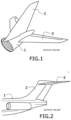
- FIG 1 discloses a Conventional tail known in the state of the art.
- This kind of tail comprises the vertical tail plane (VTP) (2) joined to the upper area of the rear fuselage section (1) and the horizontal tail plane (HTP) (3) crosses and is attached to the internal structure of the rear fuselage section (1).
- VTP vertical tail plane
- HTP horizontal tail plane
- FIG. 2 discloses a T-Tail configuration known in the state of the art.
- the horizontal tail plane (HTP) (3) is attached to the vertical tail plane (VTP) (2) at its upper part.
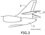
- Figure 3 discloses a Cross-Tail configuration known in the state of the art.
- the horizontal tail plane (HTP) (3) crosses the vertical tail plane (VTP) (2) near its middle part.
- FIG 4 discloses an upper shell of the rear fuselage section (1) showing the structural attachment of the vertical tail plane (VTP) (2).
- the rear fuselage section (1) comprises a skin (1.1) and internal reinforcing members, specifically, frames (1.3).
- the attachment of the vertical tail plane (VTP) (2) comprises vertical tail plane attachments (1.2) that are joined to the frames (1.3) and that crosses the skin (1.1) protruding from it (1.1) towards the vertical tail plane (VTP) (2).
- the shown attachment comprises pairs of lugs, each pair of lugs located between two consecutives frames (1.3).
- Figure 4 also discloses an embodiment of the attachment assembly attaching the framework (33) to the rear fuselage section (1).
- the attachment assembly crosses the skin (1.1) and extends between the frames (1.3) of the rear fuselage section (1) and the framework (33).
- the attachment assembly shown in figure 4 comprises:
- Figure 4 also illustrates the attachment assembly further comprising a fitting (4.2) configured for bearing the lateral loads of the horizontal tail plane (HTP) (3).
- Said fitting (4.2) for bearing lateral loads extends between the two lugs of the rear attachment (4) and is aligned with the pivot (4.1).
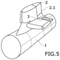
- Figure 5 discloses a perspective view of an embodiment of the invention. An aircraft empennage is shown in which are depicted:
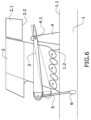
- Figure 6 discloses a rear fuselage section (1) comprising vertical tail plane attachments (1.2) protruding from the skin (1.1) and being attached to the vertical tail plane (VTP) (2).
- the shown vertical tail plane attachments (1.2) comprises three lugs.
- a continuous fitting can be implemented.
- the horizontal tail plane (HTP) (3) is located at the lower part of the vertical tail plane (VTP) (2), i.e., it is located adjacent to the skin (1.1) of the rear fuselage section (1) at the root area of the vertical tail plane (VTP) (2).
- the horizontal tail plane (HTP) (3) is trimmable.
- FIG. 7 discloses an embodiment of the invention showing a trimmable horizonal tail plane (HTP) (3) comprising:
- the rear attachment (4) is attached to the rear spar (35) of the framework (33).
- the rear attachment (4) is also attached to the rear fuselage section (1), as it is shown in figure 6 .
- the joint of the rear attachment (4) with the rear spar (35) is configured to be a pivot (4.1) of the trimmable horizontal tail plane (HTP) (3) as shown in figure 6 .
- Figure 7 also discloses a plan view of the fitting (4.2) for bearing the lateral loads of the horizontal tail plane (HTP) (3) that extends between the two lugs of the rear attachment (4) and is aligned with the pivot (4.1).
- HTP horizontal tail plane
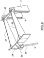
- figure 8 does not show the aforementioned fitting (4.2) to better show the rear spar (35).
- the front attachment (5) is connected to the front spar (34) of the framework (33).
- the front attachment (5) is also connected to the rear fuselage section (1), as it is shown in figure 6 .
- the front attachment (5) is configured to move the trimmable horizontal tail plane (HTP) (3) around the pivot (4.1) to control the angle of rotation of the horizontal tail plane (HTP) (3).
- the front attachment (5) comprises an endless screw. Additionally, the front attachment (5) comprises an actuator (6), a trimmable horizontal stabilizers actuator (THSA), which is configured to control the angle of rotation of the horizontal tail plane (HTP) (3).
- the actuator (6) is connected to the endless screw.
- the endless screw is attached to the front attachment (5).
- the actuator (6) is placed inside the rear fuselage section (1), i.e., located on the side of the skin towards the median plane of the fuselage section.
- the skin (1.1) of the rear fuselage section (1) comprises an opening to allow the endless screw to pass through it.
- the vertical tail plane (VTP) (2) design is not penalized by the horizontal tail plane (HTP) (3) trimming actuation like in the case of the T-Tail and Cross-Tail configurations in which the vertical tail plane (VTP) (2) inner structure is impacted.
- the rear attachment (4) comprises a lug, specifically two lugs. Each lug is joined to the rear spar (35). Moreover, the two lugs are located aligned with the longitudinal direction of the framework ribs (36, 37) to minimize the effect of the loads on the rear spar (35).
- the attachment of these lugs to the framework (33) is implemented through bolts.
- the front attachment (5) is placed near the longitudinal center of the front spar (34), to minimize the momentum by reducing the distance to the endless screw. More specifically, the front attachment (5) comprises two fittings (55) as it is shown in figure 8 .
- the framework (33) comprises two spars, front (34) and rear (35), and two ribs, left (36) and right (37).
- the horizontal tail plane (HTP) (3) lateral boxes to the framework (33)
- the front spars (31.1, 32.1) and rear spars (31.2, 32.2) of the horizontal tail plane (HTP) (2) lateral boxes (31, 32) are joined respectively to the front spar (34) and rear spar (35) of the framework (33).
- single lap-shear joints are used.
- VTP vertical tail plane
- HTP horizontal tail plane
- lateral box covers they may be connected to the framework (33) by means of different structural solutions, like a single shear joint or a tension joint.
- FIG. 5 and 6 shows the horizontal tail plane (HTP) (3) located in the root area of the vertical tail plane (VTP) (2).
- the vertical tail plane (VTP) (2) comprises a rudder (2.1).
- the rudder (2.1) comprises a lower edge (2.2) located adjacent to the rear attachment (4) of the horizontal tail plane (HTP) (3) with respect to the vertical direction of the aircraft empennage.
- the horizontal tail plane (HTP) (3) may be located in an upper position of the vertical tail plane (VTP) (2).
- the framework (33) Since the inner area of the framework (33) is used in order to allocate the vertical tail plane (VTP) (2), the framework (33) is reinforced by means of corner fittings, ensuring there is no clash with the vertical tail plane (VTP) (2) surrounding structure.
- the framework (33) can be made in one piece. Another possibility is to have composite spars (34, 35) and ribs (36, 37) and metallic corner fittings to joint these elements among themselves.
- the framework (33) may be manufactured together with one of the lateral torsion boxes (31, 32) or even the lateral torsion boxes (31, 32) and the framework (33) may be manufactured as one part.
- the framework (33) may be covered by a fairing.
- the front and rear fairings of the vertical tail plane (VTP) (2) must have cut-outs where the framework (33) crosses their surface. These cut-outs must be big enough to grant rotation of the horizontal tail plane (HTP) (3), for example, +1o upwards and +15° downwards.
- the empennage comprises a dorsal fin (60) as shown in figure 9 .
- the dorsal fin (60) closes the gap between the framework (33) and the vertical tail plane (VTP) (2) to minimize the aerodynamic drag.
- the surface of the dorsal fin (60) comprises at least two flat portions, one on each of its port and starboard sides, where the horizontal tail plane (HTP) (3) fairing is in contact with the dorsal fin (60), so as to let the HTP (3) move upward and downward.
Landscapes
- Engineering & Computer Science (AREA)
- Aviation & Aerospace Engineering (AREA)
- Mechanical Engineering (AREA)
- Automation & Control Theory (AREA)
- Body Structure For Vehicles (AREA)
Description
- The present invention relates to an aircraft empennage or tail configuration. The aircraft empennage comprises the horizontal tail plane (HTP) located at the vertical tail plane (VTP) root area.
- The empennage, also known as tail, tail assembly or tail configuration, is a structure at the rear of an aircraft that provides stability during take-off and flight.
- The empennage is the whole tail structure and comprises the rear fuselage, the vertical stabilizer or vertical tail plane (VTP) and the horizontal stabilizer or horizontal tail plane (HTP). It also includes the rudder and elevators.
- The optimization of the wet surfaces along with the weight and size of the horizontal tail plane (HTP) and the vertical tail plane (VTP) is relevant to improve aircraft performance.
- Various configurations of tail assemblies can be found in the literature for commercial and defence aircrafts. The three most relevant tail assemblies are explained below: Conventional, T-Tail and Cross-Tail.
- While the position of the vertical tail plane (VTP) is the same in all three configurations mentioned, the position of the horizontal tail plane (HTP) varies from the top of the vertical tail plane (VTP) structure to the middle section of the rear fuselage.
- These positions not only modify the aerodynamics of the whole aircraft, but also affect the rear fuselage and vertical tail plane (VTP) structures. The area where the horizontal tail plane (HTP) is attached must be reinforced, which increases the weight and cost of the aircraft.
- The Conventional tail is the most common configuration of the empennage in commercial aircrafts. This kind of tail comprises the vertical tail plane (VTP) joined to the upper area of the rear fuselage. The horizontal tail plane (HTP) is attached to the internal structure of the rear fuselage.
- The attachment of the horizontal tail plane (HTP) to the middle section of the rear fuselage is performed by several fittings and structural bars connected to the inner frame of the rear fuselage.
- Since the horizontal tail plane (HTP) is typically trimmable, it is necessary to modify the rear fuselage at the interface with the horizontal tail plane (HTP) to allow its movement as follows:
- A significant cut-out in the rear fuselage is required to locate the horizontal tail plane (HTP) and to provide sufficient clearance to avoid any clash during its trimming movement. Several reinforcements are performed as beams and high loaded frames to reinforce this cut-out and redistribute the loads.
- The last frame of the rear fuselage is left open to introduce the horizontal tail plane (HTP) into the rear fuselage during final assembly operations of the aircraft. It penalizes the structural efficiency of the rear fuselage. The last frame is closed by a lattice structure to fulfil interchangeability requirements to replace the horizontal tail plane (HTP) if needed.
- The rear fuselage aerodynamic contour is modified around the cut-outs. A double curvature area is performed to make it compatible with the trimming movement of the horizontal tail plane (HTP). The double curvature area also minimizes parasite aerodynamic drag, thanks to the local installation of a fairing.
- The main disadvantages of the Conventional tail, with respect to the structure, use and aerodynamics of the aircraft are:
- Since the connection between the horizontal tail plane (HTP) and the rear fuselage is performed inside the fuselage, a significant part of the horizontal tail plane (HTP) is hidden inside the rear fuselage. This hidden part is not useful for aircraft control. Therefore, the total size of the horizontal tail plane (HTP) is increased to compensate for this non-wetted area, penalizing the component drag, weight and cost.
- As the horizontal tail plane (HTP) is partially located inside the rear fuselage, this fuselage section is highly penalized in terms of weight and cost, due to the additional structural reinforcement needed to redistribute the loads around the cut-out area. Additionally, a strut structure in the closing frame is used due to the horizontal tail plane (HTP) interchangeability requirements, which is not the optimal solution in terms of weight.
- The manufacturing and assembly of the rear fuselage is penalized due to the high complexity involved in the production process of the double curvature shape around the cut-out area.
- In addition, the use of the fuselage interior to accommodate the horizonal tail plane (HTP) junction eliminates the possibility of using that space for other purposes, such us the location of the auxiliary power unit (APU), passenger boarding, systems allocation, etc. It reduces the effective capacity of the aircraft and make it necessary to enlarge the fuselage to locate them impacting on drag, weight and cost.
- Due to the low position of the horizontal tail plane (HTP), the possibility of impact from different objects projected from the runway and of accidents during ground operations is higher than in other empennage configurations.
- T-Tail configuration is used in cases where the engines are placed in the tail cone or the wings are placed high or the space inside the rear fuselage is needed.
- In this configuration, the horizontal tail plane (HTP) is attached to the vertical tail plane (VTP) at its upper part, which generates the T shape that gives the name to this configuration.
- The main disadvantages of the T-Tail configuration are:
- The location of the horizontal tail plane (HTP) at the top of the vertical tail plane (VTP) represents an increase in the loads that the vertical tail plane (VTP) must bear. Firstly, because the weight and loads of the horizontal tail plane (HTP) must be carried by the vertical tail plane (VTP) structure. Secondly, because the pivot point's distance in a trimmable horizontal tail plane (HTP) is much lower as its attachment is located in the narrowest area of the vertical tail plane (VTP), which increases the bending and twisting loads. Consequently, the vertical tail plane (VTP) structure is penalized in terms of weight and cost.
- Since the attachment of the horizontal tail plane (HTP) is performed at the top of the vertical tail plane (VTP), the horizontal tail plane (HTP) lateral loads cannot be adequately supported. Therefore, the fittings must bear higher lateral loads at the same point. This fact increases the complexity of the structure and makes high performance materials necessary, which penalizes the weight and cost of the structure.
- Furthermore, the maintenance of the horizontal tail plane (HTP) is complicated due to its higher position.
- An intermediate solution between the Conventional and the T-Tail is found in the Cross-Tail. The horizontal tail plane (HTP) crosses the vertical tail plane (VTP) near its middle part. It represents a compromise between the two before explained configurations.
- In this configuration, the loads from the horizontal tail plane (HTP) are transmitted to the vertical tail plane (VTP). To reinforce the lower section of the vertical tail plane (VTP) is required.
- When installing the horizontal tail plane (HTP), the load path of spars, stringers, and skins of the vertical tail plane (VTP) is interrupted. After installing the horizontal tail plane (HTP), this load path is restored by means of several reinforcements.
- The main disadvantages of the Cross-Tail empennage are:
- The structure of the lower portion of the vertical tail plane (VTP) must be designed stiffer and stronger due to the high loads it bears. This increases its weight and cost.
- Since the attachment of the horizontal tail plane (HTP) is performed at the middle part of the vertical tail plane (VTP), the horizontal tail plane (HTP) lateral loads cannot be adequately supported. Consequently, the fittings must bear higher lateral loads at the same point. This fact increases the complexity of the structure and makes high performance materials necessary, which penalizes the weight and cost of the structure.
- The vertical tail plane (VTP) is cut into two different parts by the horizontal tail plane (HTP). Several reinforcements are required to ensure the load transfer from the tip to the root of the vertical tail plane (VTP). Therefore, the overall vertical tail plane (VTP) weight and cost increases.
- In case of a trimmable horizontal tail plane (HTP), the external surface and the internal structure of the vertical tail plane (VTP) must be modified to locate the trimming actuator. Big holes in the vertical tail plane (VTP) ribs are performed to avoid any clash with the screw jack connection. This fact penalizes the overall vertical tail plane (VTP) weight and increases the complexity of the vertical tail plane (VTP) design and maintenance.
- It is known document
DE102005003297 disclosing horizontal and vertical tails connecting barrel shaped fuselage rear section having a horizontal tail section with end frames connected with each other by torsion boxes and longitudinally reinforced braces. - It is also known document
EP3090939 disclosing systems and methods provided for the mitigation of vibrational forces acting on a horizontal stabilizer of an aircraft. - The object of this present invention is to provide a configuration of the aircraft empennage that improves the horizontal tail plane (HTP) efficiency without penalizing the surrounding components, mainly the vertical tail plane (VTP) and rear fuselage section.
- The aircraft empennage object of the invention is an empennage with a horizontal stabilizer interfacing at the vertical stabilizer root.
The aircraft empennage object of the invention comprises: - A vertical tail plane (VTP).
- A rear fuselage section. This rear fuselage section comprises skin and internal reinforcing members, i.e., reinforcing members located on the side of the skin towards the median plane of the fuselage section. For instance, frames and stringers. The vertical tail plane is attached to the rear fuselage section by means of an attachment assembly extending from the internal reinforcing members to the vertical tail plane (VTP). Thus, part of the attachment assembly crosses the skin of the rear fuselage section.
- A horizontal tail plane (HTP). The horizontal tail plane (HTP) may be trimmable or fixed.
- Two lateral torsion boxes.
- A framework located between the two lateral torsion boxes; the framework being connected to the two lateral torsion boxes. The framework comprises a front spar, a rear spar and two ribs extending or spanning between the front spar and the rear spar. Each rib is adjacent, i.e., not distant or not situated at a great distance, to a lateral torsion box. Thus, the framework is a parallelogram, i.e., it comprises four sides. The framework is hollow and encloses a portion of the vertical tail plane (VTP) along the spanwise direction of the vertical tail plane (VTP). Therefore, the framework of the horizontal tail plane (HTP) surrounds a longitudinal section of the vertical tail plane (VTP). A cross-section of the vertical tail plane (VTP) is surrounded or enclosed by the parallelogram formed by the two spars and the two ribs. In this way, the vertical tail plane (VTP) crosses the horizontal tail plane (HTP), specifically through the opening formed by the framework.
- As known, in a horizontal tail plane (HTP) spars run spanwise to the horizontal plane (HTP) and ribs run chordwise. Therefore, the front and rear spar of the framework are located spanwise to the horizontal tail plane (HTP) and the two ribs are located chordwise to the horizontal tail plane (HTP).
The aircraft empennage comprises an attachment assembly attaching the framework to the rear fuselage section. The attachment assembly extends between the internal reinforcing members of the rear fuselage section and the framework and, therefore, the attachment assembly crosses the skin of the rear fuselage section. In an embodiment, the attachment assembly may be attached to a frame of the rear fuselage section.
In an embodiment, the attachment assembly attaching the framework to the rear fuselage section comprises: - A rear attachment extending between the internal reinforcing members of the rear fuselage section and the rear spar of the framework and crossing the skin. For instance, the rear attachment may protrude from the skin towards the framework of the rear fuselage section.
- A front attachment extending between the internal reinforcing members of the rear fuselage section and the front spar of the framework and also crossing the skin.
- One of the advantages of the invention is that, in an embodiment, it allows the horizontal tail plane (HTP) to be positioned at the vertical tail plane (VTP) root area to allow both:
- to have the horizontal tail plane (HTP) entirely outside of the rear fuselage section,
- to avoid the impact of the horizontal tail plane (HTP) structure and loads on the vertical tail plane (VTP).
- The root area is the part of the vertical tail plane (VTP) that is closest to the rear fuselage section. The opposite end of the vertical tail plane (VTP) from the root is the tip.
- The vertical tail plane root area covers up to the 10% or 15% of the spanwise length of the vertical tail plane (VTP) measured from the skin of the rear fuselage section.
- In an embodiment, the framework of the horizontal tail plane is located adjacent to the skin of the rear fuselage section with respect to the vertical direction of the aircraft empennage. Adjacent means that it is located not distant to the skin. The distance may vary between both elements from being in contact to having a clearance between them.
- The interfaces of the horizontal tail plane (HTP) and of the vertical tail plane (VTP) with the rear fuselage section are performed by means of the framework to avoid any clash between both components.
- In addition, the attachments of the horizontal tail plane (HTP) and of the vertical tail plane (VTP) to the rear fuselage section are located in a single area, minimizing the reinforcements required for the structure, decreasing the overall weight and cost.
- More particularly, the above-mentioned technical features stablish the horizontal tail plane (HTP)-vertical tail plane (VTP)-rear fuselage section interfaces as follows.
- The horizontal tail plane (HTP) structure comprises two lateral torsion boxes joined to the framework located between both lateral torsion boxes. This framework is connected to the rear fuselage section through an attachment assembly.
- In an embodiment, the horizontal tail plane (HTP) may be trimmable. The connection between the rear attachment of the attachment assembly and the framework is configured to be a pivot of the trimmable horizontal tail plane and the front attachment is configured to move the trimmable horizontal tail plane around the pivot to control the angle of rotation of the horizontal tail plane.
- In an embodiment, the front attachment is an endless screw. In an embodiment, the rear attachment comprises two lugs. The endless screw is connected to a trimmable horizontal stabilizer actuator (THSA) to control the angle of rotation.
- Once the horizontal tail plane (HTP) is attached to the rear fuselage section, the vertical tail plane (VTP) is placed inside the framework. The vertical tailplane (VTP) keeps the same interface design solution to be attached to the rear fuselage section known in the state of the art.
- In case of a trimmable horizontal tail plane (HTP), since the horizontal tail plane (HTP) moves with respect to the vertical tail plane (VTP) and the rear fuselage, a standard clearance is left between the framework and the other two structures to avoid any clash.
- In the embodiment where the horizontal tail plane (HTP) is trimmable and it is located in the root area of the vertical tail plane (VTP), the distance between the horizontal tail plane (HTP) in a straight position and the skin of the rear fuselage section is determined by the maximum trimming angle of the horizontal tail plane (HTP). This maximum angle defines the necessary distance from the skin according to the fixing points and the size of the horizontal tail plane (HTP).
- The horizontal tail plane (HTP) framework comprises two spars, front and rear, and two ribs, left and right.
- In an embodiment, in order to attach the horizontal tail plane (HTP) lateral boxes to the framework, the front spars of the lateral boxes and the front spar of the framework are connected and the rear spars of the lateral boxes and the rear spar of the framework are connected.
- The invention achieves several advantages with respect to the solutions known from the state of the art. The most important are savings in terms of drag, weight and industrial costs, also including some configuration opportunities, as detailed below:
- As the horizontal tail plane (HTP) is located outside of rear fuselage section, the entire surface of the horizontal tail plane (HTP) is wet. This makes it possible to have a smaller horizontal tail plane (HTP) with the same handling qualities, reducing drag, weight, and cost.
- The claimed configuration has a better structural efficiency than Cross-Tail and T-Tail. The horizontal tail plane (HTP) structure and loads do not impact on the vertical tail plane (VTP). It is not necessary to make the vertical tail plane (VTP) stiffer to support the loads from the horizontal tail plane (FTP). It is not necessary to interrupt the vertical tail plane (VTP) loads path.
- As the horizontal tail plane (HTP) is located outside the rear fuselage section, the fuselage weight and cost is optimized due to the structural efficiency improvement (standard closing frame, no cut-out, ...), and due to the removal of the cut-out structural reinforcements. Besides of this, the rear fuselage contour is not penalized by the cut-out and its local double curvature. It is therefore less complicated to manufacture and assembly the rear fuselage structure. Thus, it is feasible to reduce labour hours and materials needed in the production line.
- As the structural attachments for both the vertical tail plane (VTP) and the horizontal tail plane (HTP) are defined in the same place, it is only necessary to reinforce the upper shell of the rear fuselage. Therefore, it optimizes the structural efficiency and achieves savings compared with other configurations in which several local reinforcements are required throughout the rear fuselage section due to the different load introduction locations.
- Maintainability is similar to the Conventional and Cross-Tail configuration and better than the T-Tail due to the horizontal tail plane (HTP) location in the root area of the vertical tail plane (VTP). This location is less prone to suffer accidental damages than in the Conventional configuration thanks to its higher distance to the ground.
- As there is more space available inside the rear fuselage section, it could be used for different purposes, for instance, auxiliary power unit (APU) location, passenger boarding, systems allocation, etc. It is possible to reduce the overall fuselage length and, consequently, the weight, cost and drag.
- There is a weight increase associated to the horizontal tail plane (HTP) framework due to the high stiffness requested and to the use of a framework instead of a single center joint. Despite this, this weight penalty is fully compensated or counterbalanced by the weight savings achieved thanks to the removal of the rear fuselage cut-out reinforcements and the overall reduction of the horizontal tail plane (HTP) size, achieving an overall weight saving.
- To complete the description and to provide for a better understanding of the invention, a set of drawings is provided. Said drawings form an integral part of the description and illustrate preferred embodiments of the invention. The drawings comprise the following figures.
-
Figure 1 shows a perspective view of an aircraft empennage known in the state of the art as Conventional tail. -
Figure 2 shows a lateral view of an aircraft empennage known in the state of the art as T-tail. -
Figure 3 shows a lateral view of an aircraft empennage known in the state of the art as Cross-tail. -
Figure 4 shows a perspective view of an upper shell of the rear fuselage section showing the structural attachment of the vertical tail plane (VTP) and of the horizontal tail plane (HTP). -
Figure 5 shows a perspective view of an aircraft empennage according to an embodiment of the invention. -
Figure 6 shows a schematic lateral view of an embodiment of the invention showing the interfaces between the rear fuselage section, the vertical tail plane (VTP) and the horizontal tail plane (HTP). -
Figure 7 shows a schematic plan view of the horizontal tail plane (HTP) and the vertical tail plane (VTP). -
Figure 8 shows a perspective view of an embodiment of the framework and of the front and the rear attachments to the rear fuselage section. -
Figure 9 shows a schematic plan view of an embodiment of the front spar of the framework and a dorsal fin covering the gap between the framework and the vertical tail plane (VTP). -
Figure 1 discloses a Conventional tail known in the state of the art. This kind of tail comprises the vertical tail plane (VTP) (2) joined to the upper area of the rear fuselage section (1) and the horizontal tail plane (HTP) (3) crosses and is attached to the internal structure of the rear fuselage section (1). -
Figure 2 discloses a T-Tail configuration known in the state of the art. In this configuration, the horizontal tail plane (HTP) (3) is attached to the vertical tail plane (VTP) (2) at its upper part. -
Figure 3 discloses a Cross-Tail configuration known in the state of the art. In this configuration, the horizontal tail plane (HTP) (3) crosses the vertical tail plane (VTP) (2) near its middle part. -
Figure 4 discloses an upper shell of the rear fuselage section (1) showing the structural attachment of the vertical tail plane (VTP) (2). The rear fuselage section (1) comprises a skin (1.1) and internal reinforcing members, specifically, frames (1.3). The attachment of the vertical tail plane (VTP) (2) comprises vertical tail plane attachments (1.2) that are joined to the frames (1.3) and that crosses the skin (1.1) protruding from it (1.1) towards the vertical tail plane (VTP) (2). The shown attachment comprises pairs of lugs, each pair of lugs located between two consecutives frames (1.3). -
Figure 4 also discloses an embodiment of the attachment assembly attaching the framework (33) to the rear fuselage section (1). The attachment assembly crosses the skin (1.1) and extends between the frames (1.3) of the rear fuselage section (1) and the framework (33). - The attachment assembly shown in
figure 4 comprises: - the rear attachment (4), specifically two lugs, extending between the frames (1.3) of the rear fuselage section (1) and the framework (33),
- the front attachment (5) extending between the frames (1.3) of the rear fuselage section (1) and the framework (33).
-
Figure 4 also illustrates the attachment assembly further comprising a fitting (4.2) configured for bearing the lateral loads of the horizontal tail plane (HTP) (3). Said fitting (4.2) for bearing lateral loads extends between the two lugs of the rear attachment (4) and is aligned with the pivot (4.1). -
Figure 5 discloses a perspective view of an embodiment of the invention. An aircraft empennage is shown in which are depicted: - the rear fuselage section (1),
- the vertical tail plane (VTP) (2) attached to the rear fuselage section (1), and
- the horizontal tail plane (HTP) (3) located at the root area of the vertical tail plane (2).
-
Figure 6 discloses a rear fuselage section (1) comprising vertical tail plane attachments (1.2) protruding from the skin (1.1) and being attached to the vertical tail plane (VTP) (2). - The shown vertical tail plane attachments (1.2) comprises three lugs. Alternatively, instead of having several independent lugs, a continuous fitting can be implemented.
- It also shows that the horizontal tail plane (HTP) (3) is located at the lower part of the vertical tail plane (VTP) (2), i.e., it is located adjacent to the skin (1.1) of the rear fuselage section (1) at the root area of the vertical tail plane (VTP) (2). The horizontal tail plane (HTP) (3) is trimmable.
-
Figure 6 also shows: - the rear attachment (4), and
- the front attachment (5).
-
Figure 7 discloses an embodiment of the invention showing a trimmable horizonal tail plane (HTP) (3) comprising: - The two lateral torsion boxes (31, 32).
- The framework (33) which is located between the two lateral torsion boxes (31, 32). The framework (33) is connected to the two lateral torsion boxes (31, 32). The framework (33) comprises a front spar (34), a rear spar (35) and two ribs (36, 37). Each rib (36, 37) is located adjacent to a lateral torsion box (31, 32). Moreover, the framework (33) encloses a cross-section of the vertical tail plane (VTP) (2) such that a longitudinal portion of the vertical tail plane (VTP) (2) is surrounded by the framework (33).
- The rear attachment (4) is attached to the rear spar (35) of the framework (33). The rear attachment (4) is also attached to the rear fuselage section (1), as it is shown in
figure 6 . The joint of the rear attachment (4) with the rear spar (35) is configured to be a pivot (4.1) of the trimmable horizontal tail plane (HTP) (3) as shown infigure 6 . -
Figure 7 also discloses a plan view of the fitting (4.2) for bearing the lateral loads of the horizontal tail plane (HTP) (3) that extends between the two lugs of the rear attachment (4) and is aligned with the pivot (4.1). For the sake of clarity,figure 8 does not show the aforementioned fitting (4.2) to better show the rear spar (35). - The front attachment (5) is connected to the front spar (34) of the framework (33). The front attachment (5) is also connected to the rear fuselage section (1), as it is shown in
figure 6 . The front attachment (5) is configured to move the trimmable horizontal tail plane (HTP) (3) around the pivot (4.1) to control the angle of rotation of the horizontal tail plane (HTP) (3). - In the embodiment shown in
figure 6 , the front attachment (5) comprises an endless screw. Additionally, the front attachment (5) comprises an actuator (6), a trimmable horizontal stabilizers actuator (THSA), which is configured to control the angle of rotation of the horizontal tail plane (HTP) (3). The actuator (6) is connected to the endless screw. The endless screw is attached to the front attachment (5). - In the shown embodiment, the actuator (6) is placed inside the rear fuselage section (1), i.e., located on the side of the skin towards the median plane of the fuselage section. For that reason, the skin (1.1) of the rear fuselage section (1) comprises an opening to allow the endless screw to pass through it.
- Furthermore, as the trimmable horizontal stabilizers actuator (THSA) (6) is kept inside the rear fuselage section (1), the vertical tail plane (VTP) (2) design is not penalized by the horizontal tail plane (HTP) (3) trimming actuation like in the case of the T-Tail and Cross-Tail configurations in which the vertical tail plane (VTP) (2) inner structure is impacted.
- In the shown embodiment, the rear attachment (4) comprises a lug, specifically two lugs. Each lug is joined to the rear spar (35). Moreover, the two lugs are located aligned with the longitudinal direction of the framework ribs (36, 37) to minimize the effect of the loads on the rear spar (35). The attachment of these lugs to the framework (33) is implemented through bolts.
- The front attachment (5) is placed near the longitudinal center of the front spar (34), to minimize the momentum by reducing the distance to the endless screw. More specifically, the front attachment (5) comprises two fittings (55) as it is shown in
figure 8 . - In a trimmable horizontal tail plane (HTP) (3), since the horizontal tail plane (HTP) (3) moves with respect to the vertical tail plane (VTP) (2) and the rear fuselage section (1), a standard clearance is left between the framework (33) and the other two structures in order to avoid any clash, as it is shown in
figures 6 and7 . - As previously stated, the framework (33) comprises two spars, front (34) and rear (35), and two ribs, left (36) and right (37). In order to attach the horizontal tail plane (HTP) (3) lateral boxes to the framework (33), the front spars (31.1, 32.1) and rear spars (31.2, 32.2) of the horizontal tail plane (HTP) (2) lateral boxes (31, 32) are joined respectively to the front spar (34) and rear spar (35) of the framework (33). Specifically, single lap-shear joints are used.
- In addition, on top of the high loaded frames (1.3) defined in the rear fuselage section (1) to attach the vertical tail plane (VTP) (2), one additional high loaded frame will be needed in order to bear the loads coming from the rear support fittings. This additional high-loaded frame may be an intermediate one, or the rear fuselage closing frame like in the conventional empennage configuration.
- In the case of the horizontal tail plane (HTP) (2) lateral box covers, they may be connected to the framework (33) by means of different structural solutions, like a single shear joint or a tension joint.
-
Figures 5 and6 shows the horizontal tail plane (HTP) (3) located in the root area of the vertical tail plane (VTP) (2). The vertical tail plane (VTP) (2) comprises a rudder (2.1). In the shown embodiment, the rudder (2.1) comprises a lower edge (2.2) located adjacent to the rear attachment (4) of the horizontal tail plane (HTP) (3) with respect to the vertical direction of the aircraft empennage. - In an alternative embodiment, the horizontal tail plane (HTP) (3) may be located in an upper position of the vertical tail plane (VTP) (2).
- Since the shape of the horizontal tail plane (HTP) (3) framework (33) is rectangular and the loading points from the horizontal tail plane (HTP) (3) are placed at the edges of the framework (33), it is necessary to stiffen the framework (33) in order to bear the momentum generated by these loads.
- Since the inner area of the framework (33) is used in order to allocate the vertical tail plane (VTP) (2), the framework (33) is reinforced by means of corner fittings, ensuring there is no clash with the vertical tail plane (VTP) (2) surrounding structure.
- The corner fittings and the lugs are so that the same bolts are used to attach these elements to the frame rear spar (35).
- To manufacture the framework (33), two possibilities are depicted. To mechanize the full framework (33) using high performance metals. The framework (33) can be made in one piece. Another possibility is to have composite spars (34, 35) and ribs (36, 37) and metallic corner fittings to joint these elements among themselves. In an embodiment, the framework (33) may be manufactured together with one of the lateral torsion boxes (31, 32) or even the lateral torsion boxes (31, 32) and the framework (33) may be manufactured as one part.
- The framework (33) may be covered by a fairing.
- In order to allow the placement of the horizontal tail plane (HTP) (3) and the framework (33), the front and rear fairings of the vertical tail plane (VTP) (2) must have cut-outs where the framework (33) crosses their surface. These cut-outs must be big enough to grant rotation of the horizontal tail plane (HTP) (3), for example, +1º upwards and +15° downwards.
- In addition, the empennage comprises a dorsal fin (60) as shown in
figure 9 . The dorsal fin (60) closes the gap between the framework (33) and the vertical tail plane (VTP) (2) to minimize the aerodynamic drag. The surface of the dorsal fin (60) comprises at least two flat portions, one on each of its port and starboard sides, where the horizontal tail plane (HTP) (3) fairing is in contact with the dorsal fin (60), so as to let the HTP (3) move upward and downward.
Claims (15)
- Aircraft empennage, comprising:- a vertical tail plane (2),- a rear fuselage section (1) comprising a skin (1.1) and internal reinforcing members, the vertical tail plane (2) being attached to the rear fuselage section (1),- a horizontal tail plane (3) comprising two lateral torsion boxes (31, 32), characterized in that the horizontal tail plane (3) further comprises:- a framework (33) located between the two lateral torsion boxes (31, 32) and in connection with them (31, 32), the framework (33) comprising a front spar (34), a rear spar (35) and two ribs (36, 37) extending between the front spar (34) and the rear spar (35), each rib (36, 37) adjacent to a lateral torsion box (31, 32), the framework (33) enclosing a portion of the vertical tail plane (2) along its spanwise direction,and the aircraft empennage comprising an attachment assembly attaching the framework (33) to the rear fuselage section (1), the attachment assembly crossing the skin (1.1) and extending between the internal reinforcing members of the rear fuselage section (1) and the framework (33).
- Aircraft empennage, according to claim 1, wherein the attachment assembly attaching the framework (33) to the rear fuselage section (1) comprises:- a rear attachment (4) extending between the internal reinforcing members of the rear fuselage section (1) and the rear spar (35) of the framework (33),- a front attachment (5) extending between the internal reinforcing members of the rear fuselage section (1) and the front spar (34) of the framework (33).
- Aircraft empennage, according to claim 2, wherein the horizontal tail plane (3) is trimmable, the connection between the rear attachment (4) and the framework (33) being configured to be a pivot (4.1) of the trimmable horizontal tail plane (3) and the front attachment (5) being configured to move the trimmable horizontal tail plane (3) around the pivot (4.1) to control an angle of rotation of the horizontal tail plane (3).
- Aircraft empennage, according to claim 3, wherein the front attachment (5) comprises an endless screw.
- Aircraft empennage, according to claim 4, wherein the front attachment (5) comprises an actuator (6) connected to the endless screw and configured to move the trimmable horizontal tail plane (3) around the pivot (4.1) to control the angle of rotation of the horizontal tail plane (3).
- Aircraft empennage, according to claim 5, wherein the actuator (6) is placed inside the rear fuselage section (1).
- Aircraft empennage, according to claim 6, wherein the skin (1.1) of the rear fuselage section (1) comprises an opening that allows the passage of the endless screw.
- Aircraft empennage, according to any preceding claim, wherein the framework (33) is located at the root area of the vertical tail plane (2).
- Aircraft empennage, according to claim 8, wherein the framework (33) of the horizontal tail plane (3) is located adjacent to the skin (1.1) of the rear fuselage section (1) with respect to a spanwise direction of the vertical tail plane (2).
- Aircraft empennage, according to any preceding claim, wherein the vertical tail plane (2) comprises a rudder (2.1), the rudder (2.1) comprising a lower edge (2.2) located adjacent to the rear attachment (4) of the horizontal tail plane (3) with respect to a spanwise direction of the vertical tail plane (2).
- Aircraft empennage, according to any preceding claim, wherein the two lateral torsion boxes (31, 32) comprise a front spar (31.1, 32.1) and a rear spar (31.2, 32.2) and the front spar (34) of the framework (33) being joined to the front spars (31.1, 32.1) of the lateral torsion boxes (31, 32) and the rear spar (35) of the framework (33) being joined to the rear spars (31.2, 32.2) of the lateral torsion boxes (31, 32).
- Aircraft empennage, according to any preceding claim 2 to 11, wherein the front attachment (5) is joined to the framework (33) near the longitudinal center of the front spar (34).
- Aircraft empennage, according to any preceding claim 2 to 12, wherein the rear attachment (4) comprises two lugs, each lug joined to the rear spar (35) of the framework (33) aligned with the longitudinal direction of each rib (36, 37).
- Aircraft empennage, according to any preceding claim, wherein the spars (34, 35) and the ribs (36, 37) of the framework (33) are metallic.
- Aircraft empennage, according to any preceding claim 1 to 13, wherein the spars (34, 35) and the ribs (36, 37) are made in composite materials.
Priority Applications (4)
| Application Number | Priority Date | Filing Date | Title |
|---|---|---|---|
| EP21382102.8A EP4043336B1 (en) | 2021-02-10 | 2021-02-10 | Aircraft empennage with a horizontal stabilizer interfacing at the vertical stabilizer root |
| US17/526,394 US11987343B2 (en) | 2021-02-10 | 2021-11-15 | Aircraft empennage with a horizontal stabilizer interfacing at the vertical stabilizer root |
| CA3140310A CA3140310A1 (en) | 2021-02-10 | 2021-11-24 | Aircraft empennage with a horizontal stabilizer interfacing at the vertical stabilizer root |
| CN202111422059.6A CN114940258A (en) | 2021-02-10 | 2021-11-26 | Empennage section of an aircraft with horizontal stabilizers joined at the root of the vertical stabilizer |
Applications Claiming Priority (1)
| Application Number | Priority Date | Filing Date | Title |
|---|---|---|---|
| EP21382102.8A EP4043336B1 (en) | 2021-02-10 | 2021-02-10 | Aircraft empennage with a horizontal stabilizer interfacing at the vertical stabilizer root |
Publications (2)
| Publication Number | Publication Date |
|---|---|
| EP4043336A1 EP4043336A1 (en) | 2022-08-17 |
| EP4043336B1 true EP4043336B1 (en) | 2024-04-03 |
Family
ID=74732833
Family Applications (1)
| Application Number | Title | Priority Date | Filing Date |
|---|---|---|---|
| EP21382102.8A Active EP4043336B1 (en) | 2021-02-10 | 2021-02-10 | Aircraft empennage with a horizontal stabilizer interfacing at the vertical stabilizer root |
Country Status (4)
| Country | Link |
|---|---|
| US (1) | US11987343B2 (en) |
| EP (1) | EP4043336B1 (en) |
| CN (1) | CN114940258A (en) |
| CA (1) | CA3140310A1 (en) |
Family Cites Families (2)
| Publication number | Priority date | Publication date | Assignee | Title |
|---|---|---|---|---|
| DE102005003297B4 (en) * | 2005-01-24 | 2007-03-29 | Eads Deutschland Gmbh | Aircraft with a fuselage tail section for the connection of vertical and vertical stabilizers |
| US9828084B2 (en) * | 2015-05-06 | 2017-11-28 | The Boeing Company | Vibration dampening for horizontal stabilizers |
-
2021
- 2021-02-10 EP EP21382102.8A patent/EP4043336B1/en active Active
- 2021-11-15 US US17/526,394 patent/US11987343B2/en active Active
- 2021-11-24 CA CA3140310A patent/CA3140310A1/en active Pending
- 2021-11-26 CN CN202111422059.6A patent/CN114940258A/en active Pending
Also Published As
| Publication number | Publication date |
|---|---|
| EP4043336A1 (en) | 2022-08-17 |
| US20220250735A1 (en) | 2022-08-11 |
| CN114940258A (en) | 2022-08-26 |
| US11987343B2 (en) | 2024-05-21 |
| CA3140310A1 (en) | 2022-08-10 |
Similar Documents
| Publication | Publication Date | Title |
|---|---|---|
| US6929219B2 (en) | Derivative aircraft and methods for their manufacture | |
| EP2148812B1 (en) | Wing-fuselage section of an aircraft | |
| CA2857813C (en) | Rear fuselage section of an aircraft | |
| EP2727824B1 (en) | Reinforced aircraft fuselage | |
| US7316372B2 (en) | Fuselage spar for aircraft and central sparbox provided with such a spar | |
| US20090146007A1 (en) | Methods and Systems for Attaching Aircraft Wings to Fuselages | |
| EP2311728A2 (en) | Structure of an aircraft aerofoil | |
| EP2602183B1 (en) | Aircraft rib assembly | |
| CN112977798B (en) | Wing assembly and hovercar | |
| EP3330174B1 (en) | Aircraft stabilizer leading edge integration with torsion box and fuselage | |
| EP3025954B1 (en) | Aircraft fuselage section | |
| WO2007099297A1 (en) | Aircraft wings and their assembly | |
| US20170066518A1 (en) | Aircraft rear portion comprising a vertical stabilizer having a box-section structure including a lower portion accommodated in the fuselage | |
| EP4043336B1 (en) | Aircraft empennage with a horizontal stabilizer interfacing at the vertical stabilizer root | |
| CN112533824A (en) | Method for improving the concept of a closed-wing aircraft and corresponding aircraft construction | |
| EP2540618B1 (en) | Filler panel for bulkhead to skin joint in integral tanks | |
| EP3501971B1 (en) | Aircraft rear fuselage section and manufacturing method thereof | |
| EP2889216B1 (en) | Aircraft with a trimmable horizontal stabilizer having the pivot elements in its forward side | |
| CN110510104A (en) | A kind of girder construction of aircraft wing | |
| CN112960111B (en) | Cabin door assembly of main landing gear cabin of airplane | |
| US20180162514A1 (en) | Aircraft comprising a common structure for supporting a power plant and a landing gear element | |
| US11401024B2 (en) | Fuselage sections having tapered wing rib interfaces | |
| EP4151521B1 (en) | An aircraft with a forward-swept wing in shoulder-wing configuration | |
| CN116424546A (en) | High-performance tail fin made of large-size full composite material |
Legal Events
| Date | Code | Title | Description |
|---|---|---|---|
| PUAI | Public reference made under article 153(3) epc to a published international application that has entered the european phase |
Free format text: ORIGINAL CODE: 0009012 |
|
| STAA | Information on the status of an ep patent application or granted ep patent |
Free format text: STATUS: THE APPLICATION HAS BEEN PUBLISHED |
|
| AK | Designated contracting states |
Kind code of ref document: A1 Designated state(s): AL AT BE BG CH CY CZ DE DK EE ES FI FR GB GR HR HU IE IS IT LI LT LU LV MC MK MT NL NO PL PT RO RS SE SI SK SM TR |
|
| STAA | Information on the status of an ep patent application or granted ep patent |
Free format text: STATUS: REQUEST FOR EXAMINATION WAS MADE |
|
| 17P | Request for examination filed |
Effective date: 20230209 |
|
| RBV | Designated contracting states (corrected) |
Designated state(s): AL AT BE BG CH CY CZ DE DK EE ES FI FR GB GR HR HU IE IS IT LI LT LU LV MC MK MT NL NO PL PT RO RS SE SI SK SM TR |
|
| GRAP | Despatch of communication of intention to grant a patent |
Free format text: ORIGINAL CODE: EPIDOSNIGR1 |
|
| STAA | Information on the status of an ep patent application or granted ep patent |
Free format text: STATUS: GRANT OF PATENT IS INTENDED |
|
| INTG | Intention to grant announced |
Effective date: 20231201 |
|
| GRAS | Grant fee paid |
Free format text: ORIGINAL CODE: EPIDOSNIGR3 |
|
| GRAA | (expected) grant |
Free format text: ORIGINAL CODE: 0009210 |
|
| STAA | Information on the status of an ep patent application or granted ep patent |
Free format text: STATUS: THE PATENT HAS BEEN GRANTED |
|
| AK | Designated contracting states |
Kind code of ref document: B1 Designated state(s): AL AT BE BG CH CY CZ DE DK EE ES FI FR GB GR HR HU IE IS IT LI LT LU LV MC MK MT NL NO PL PT RO RS SE SI SK SM TR |
|
| REG | Reference to a national code |
Ref country code: CH Ref legal event code: EP |
|
| REG | Reference to a national code |
Ref country code: DE Ref legal event code: R096 Ref document number: 602021011241 Country of ref document: DE |
|
| REG | Reference to a national code |
Ref country code: IE Ref legal event code: FG4D |
|
| REG | Reference to a national code |
Ref country code: LT Ref legal event code: MG9D |
|
| REG | Reference to a national code |
Ref country code: NL Ref legal event code: MP Effective date: 20240403 |
|
| REG | Reference to a national code |
Ref country code: AT Ref legal event code: MK05 Ref document number: 1672020 Country of ref document: AT Kind code of ref document: T Effective date: 20240403 |