EP4043305A1 - A pneumatic braking system for an axle of a vehicle - Google Patents
A pneumatic braking system for an axle of a vehicle Download PDFInfo
- Publication number
- EP4043305A1 EP4043305A1 EP21156432.3A EP21156432A EP4043305A1 EP 4043305 A1 EP4043305 A1 EP 4043305A1 EP 21156432 A EP21156432 A EP 21156432A EP 4043305 A1 EP4043305 A1 EP 4043305A1
- Authority
- EP
- European Patent Office
- Prior art keywords
- pressure
- pneumatic
- port
- braking system
- outlet port
- Prior art date
- Legal status (The legal status is an assumption and is not a legal conclusion. Google has not performed a legal analysis and makes no representation as to the accuracy of the status listed.)
- Granted
Links
- 238000002955 isolation Methods 0.000 claims abstract description 135
- 230000009471 action Effects 0.000 claims description 10
- 238000013329 compounding Methods 0.000 description 20
- 230000000694 effects Effects 0.000 description 6
- 230000008901 benefit Effects 0.000 description 3
- 238000011144 upstream manufacturing Methods 0.000 description 3
- 238000011217 control strategy Methods 0.000 description 2
- 230000010354 integration Effects 0.000 description 2
- 230000007246 mechanism Effects 0.000 description 2
- 230000004044 response Effects 0.000 description 2
- 230000001052 transient effect Effects 0.000 description 2
- 230000007704 transition Effects 0.000 description 2
- 238000002485 combustion reaction Methods 0.000 description 1
- 150000001875 compounds Chemical class 0.000 description 1
- 238000010276 construction Methods 0.000 description 1
- 238000007726 management method Methods 0.000 description 1
- 239000012528 membrane Substances 0.000 description 1
- 230000002265 prevention Effects 0.000 description 1
- 238000005096 rolling process Methods 0.000 description 1
- 238000007789 sealing Methods 0.000 description 1
Images


Classifications
-
- B—PERFORMING OPERATIONS; TRANSPORTING
- B60—VEHICLES IN GENERAL
- B60T—VEHICLE BRAKE CONTROL SYSTEMS OR PARTS THEREOF; BRAKE CONTROL SYSTEMS OR PARTS THEREOF, IN GENERAL; ARRANGEMENT OF BRAKING ELEMENTS ON VEHICLES IN GENERAL; PORTABLE DEVICES FOR PREVENTING UNWANTED MOVEMENT OF VEHICLES; VEHICLE MODIFICATIONS TO FACILITATE COOLING OF BRAKES
- B60T13/00—Transmitting braking action from initiating means to ultimate brake actuator with power assistance or drive; Brake systems incorporating such transmitting means, e.g. air-pressure brake systems
- B60T13/10—Transmitting braking action from initiating means to ultimate brake actuator with power assistance or drive; Brake systems incorporating such transmitting means, e.g. air-pressure brake systems with fluid assistance, drive, or release
- B60T13/66—Electrical control in fluid-pressure brake systems
- B60T13/68—Electrical control in fluid-pressure brake systems by electrically-controlled valves
- B60T13/683—Electrical control in fluid-pressure brake systems by electrically-controlled valves in pneumatic systems or parts thereof
-
- B—PERFORMING OPERATIONS; TRANSPORTING
- B60—VEHICLES IN GENERAL
- B60T—VEHICLE BRAKE CONTROL SYSTEMS OR PARTS THEREOF; BRAKE CONTROL SYSTEMS OR PARTS THEREOF, IN GENERAL; ARRANGEMENT OF BRAKING ELEMENTS ON VEHICLES IN GENERAL; PORTABLE DEVICES FOR PREVENTING UNWANTED MOVEMENT OF VEHICLES; VEHICLE MODIFICATIONS TO FACILITATE COOLING OF BRAKES
- B60T13/00—Transmitting braking action from initiating means to ultimate brake actuator with power assistance or drive; Brake systems incorporating such transmitting means, e.g. air-pressure brake systems
- B60T13/10—Transmitting braking action from initiating means to ultimate brake actuator with power assistance or drive; Brake systems incorporating such transmitting means, e.g. air-pressure brake systems with fluid assistance, drive, or release
- B60T13/24—Transmitting braking action from initiating means to ultimate brake actuator with power assistance or drive; Brake systems incorporating such transmitting means, e.g. air-pressure brake systems with fluid assistance, drive, or release the fluid being gaseous
- B60T13/26—Compressed-air systems
- B60T13/261—Compressed-air systems systems with both indirect application and application by springs or weights and released by compressed air
-
- B—PERFORMING OPERATIONS; TRANSPORTING
- B60—VEHICLES IN GENERAL
- B60T—VEHICLE BRAKE CONTROL SYSTEMS OR PARTS THEREOF; BRAKE CONTROL SYSTEMS OR PARTS THEREOF, IN GENERAL; ARRANGEMENT OF BRAKING ELEMENTS ON VEHICLES IN GENERAL; PORTABLE DEVICES FOR PREVENTING UNWANTED MOVEMENT OF VEHICLES; VEHICLE MODIFICATIONS TO FACILITATE COOLING OF BRAKES
- B60T17/00—Component parts, details, or accessories of power brake systems not covered by groups B60T8/00, B60T13/00 or B60T15/00, or presenting other characteristic features
- B60T17/08—Brake cylinders other than ultimate actuators
- B60T17/083—Combination of service brake actuators with spring loaded brake actuators
-
- B—PERFORMING OPERATIONS; TRANSPORTING
- B60—VEHICLES IN GENERAL
- B60T—VEHICLE BRAKE CONTROL SYSTEMS OR PARTS THEREOF; BRAKE CONTROL SYSTEMS OR PARTS THEREOF, IN GENERAL; ARRANGEMENT OF BRAKING ELEMENTS ON VEHICLES IN GENERAL; PORTABLE DEVICES FOR PREVENTING UNWANTED MOVEMENT OF VEHICLES; VEHICLE MODIFICATIONS TO FACILITATE COOLING OF BRAKES
- B60T7/00—Brake-action initiating means
- B60T7/02—Brake-action initiating means for personal initiation
- B60T7/04—Brake-action initiating means for personal initiation foot actuated
- B60T7/042—Brake-action initiating means for personal initiation foot actuated by electrical means, e.g. using travel or force sensors
Definitions
- This disclosure relates to vehicle braking systems with a compound management function. It relates in particular to electronically control pneumatic braking systems for heavy duty vehicles like trucks, buses, off-highway vehicles.
- Electronic anti-compounding function operates when vehicle is operated in regular conditions, which means when all electronic systems are electrically powered-up, and without any electrical fault present in the braking system.
- anti-compounding function When electrical systems are switched-off, or not electrically powered, electronic anti-compounding function is not active. In such a case, anti-compounding function has to be provided in a different way.
- a goal of the present invention is to provide a solution in which anti-compounding function is performed throughout the use cases of the vehicle.
- anti-compounding should be available even when electronic systems are not powered-up.
- Proposed solution is based on a new concept of isolation valve provided on the pneumatic back-up line of the braking system.
- a pneumatic braking system for an axle of a vehicle comprising:
- the first air control pressure is delivered to the regulation unit only when the pressure in the parking brake chamber is high enough, i.e higher than a first predetermined threshold.
- This high pressure in the parking brake chamber can exist only if the parking brake is released.
- service brakes can be activated only if parking brake is released.
- Anti-compounding function is achieved without any need to have the electronic systems energized. This gives the advantage that even in particular use cases during which some electronic systems of the truck are disconnected, like for example during vehicle servicing in a workshop, service brakes can only be applied by a mechanic while parking brake is already released. Reliability issues associated with brake compounding are avoided.
- the electro pneumatic modulator unit when the isolation device is electrically energized, is configured for delivering a first modulated air pressure to the service brake chamber, the first modulated air pressure being controlled only by the regulation unit in response to electrical control signals.
- the electrical control signals are sent by an ecu braking system.
- the isolation device comprises an on-off solenoid valve, the on-off solenoid valve comprising :
- the isolation device comprises a select low valve and an electromagnetic isolation valve
- the isolation device comprises a pneumatic isolation valve and an electromagnetic isolation valve
- the isolation device is included in the electro pneumatic modulator unit.
- the isolation device is included in a foot brake modulator, the foot brake modulator being configured for delivering the first air control pressure and being a separated unit from the electro pneumatic modulator unit.
- the isolation device is separated from electro pneumatic modulator unit and separated from the foot brake modulator.
- the parking brake chamber pressure first threshold for allowing or preventing the delivery of the first air control pressure to the regulation unit is comprised between 3,5 Bar and 4,5 Bar.
- the second predetermined threshold is comprised between 3 and 4 Bar
- the third predetermined threshold is comprised between 2 and 2,8 Bar.
- the parking brake unit comprises an electronic control unit configured for delivering the second modulated air pressure to the parking brake pneumatic chamber.
- the pneumatic braking system further comprises:
- the isolation device is included in the electro pneumatic modulator unit.
- the invention also relates to a braking system assembly, comprising :
- the invention relates as well to a commercial vehicle comprising a pneumatic braking system as previously described or comprising a braking system assembly as previously described.
- Figure 14 illustrates in a non-limiting manner a truck 150 with three axles, a front steering axle 61 and two rear axles 62 and 63.
- the truck 150 comprises a pneumatic braking system 100.
- the truck considered here can be the tractor unit in a tractor/trailer configuration. It can also be a utility 'carrier' truck.
- the proposed configuration is also valid for any kind of heavy-duty vehicles, including buses and construction vehicles.
- Figure 1 is a schematic of the layout of the braking system 100. Only the most relevant components have been represented. Plain lines represent pneumatic lines supplying delivery pressure to the various air brakes actuators. Dotted lines represent pneumatic lines supplying control pressure to the devices that control the operation of the brake actuators.
- Braking system 100 comprises a central braking electronic control unit 20.
- This central braking unit manages the operation of the braking system 100. It includes an electro pneumatic modulator 2, a foot brake modulator 9, a parking brake unit 7, one or several service brake actuators 1, one or several parking brake actuators 4.
- the braking system 100 of the truck comprises a service brake and a parking brake.
- the service brake is configured to apply a braking effort on an axle of the vehicle when the vehicle is rolling.
- the service brake is controlled by the driver by his foot pressure on a brake pedal.
- the parking brake is configured to apply a braking effort on an axle of the vehicle when the vehicle is parked.
- Foot brake modulator 9 delivers a first air control pressure P1 that increases when the drivers increases his effort on the brake pedal of the vehicle.
- the electro pneumatic modulator 2 receives an air supply pressure P_R and delivers a modulated air pressure P_s to the service brake actuators 1.
- Electro pneumatic modulator unit 2 is configured to control wheel speed deceleration. It therefore ensures wheels anti-lock function and is part of the stability control function of the vehicle.
- Electro pneumatic modulator unit 2 is configured to receive braking requests from the central electronic control unit 20.
- electro pneumatic modulator unit 2 is configured to communicate with central electronic control unit 20 by digital communication protocol. CAN protocol can for example be implemented.
- the various electronic systems are connected to an electrical harness. Electrical power is provided by a battery which is charged by an alternator for trucks with internal combustion engines.
- the air supply pressure P_R is provided by a service brake reservoir 26.
- Service brake reservoir 26 is supplied in compressed air by an air compressor 28 which compresses atmospheric air and increases its pressure above atmospheric pressure. Pressure in the service brake reservoir 26 is controlled by a regulation unit which has not been represented, so called governor. Nominal reservoir pressure is for example 8 bar.
- the parking brake unit 7 is configured for receiving a second supply air pressure P_R2. Second supply air pressure is delivered by a second air reservoir which is parking brake reservoir 27.
- Driver's service braking requests are interpreted by the system from the position of the brake pedal in the foot brake modulator 2. Brake pedal position is monitored by redundant position sensors. The pedal position information is used by the central braking ecu to control the various actuators in order to achieve the driver request. Other systems like anti-locking or stability control may override driver's request.
- a first air control pressure P1 representative of a vehicle driver's braking request, is delivered by a foot brake modulator 9.
- First air control pressure P1 increases when a depression applied by the vehicle driver on the brake pedal increases.
- the parking brake is configured to have only two stable operation modes: a first mode in which the parking brake is released, a second mode in which the parking brake is activated with nominal braking force.
- the parking brake can be activated or released by the driver by pulling a lever, or knob.
- Figure 10 describes schematically the electro pneumatic modulator 2.
- the modulated air pressure P_s is obtained by modulation of the air supply pressure P_R and atmospheric pressure.
- modulated air pressure P_s is inferior or equal to air supply pressure P_R.
- the electro pneumatic modulator 2 comprises a relay valve 37 and two electrovalves 35, 36.
- the detailed operation of the regulation unit is known and will not be extensively described.
- the two electrovalves 35 and 36 can adjust the outlet pressure P_s which is supplied to the service brake chambers 3. This pressure can be continuously adjusted between the supply pressure P_R and the atmospheric pressure Patm. Pulse width modulation control of the two electrovalves 35, 36 achieves a closed loop control of the pressure delivered to the service brake.
- Relay valve 37 receives the first air control pressure P1.
- P1 pressure may control the relay valve so that the supply pressure P_R is delivered to the service brake chamber 3.
- Figure 9 describes a brake actuator integrated in the pneumatic brake system 100.
- the actuator has the general shape of a cylinder having an axis X1. This cylinder forms an enclosure having two chambers 3, 6 separated by a wall and a sealing member. An actuation rod 25 protudes from the housing. One chamber 3 is dedicated to the service brake and the second chamber 6 is dedicated to the parking brake.
- the service brake chamber 3 has a first mobile piston 3a that can reciprocate in a first sealed cavity.
- the first piston 3a and the actuation rod 25 are rigidly connected together. Pressure applied in the service brake chamber 3 moves the first mobile piston 3a and the actuation rod 25 in a first direction.
- the actuation rod 25 in turn activates a mechanism, not represented, that pushes the brake shoes against the brake drums, or that pushes brake pads against brake disk. Braking force is thus generated on the axle.
- the parking brake chamber 6 has a second mobile piston 6a that can reciprocate in a second cavity sealed by a second mobile membrane.
- the first 3a and second 6a pistons are coaxial.
- An internal rod 6b is rigidly connected to the second piston 6a.
- a preloaded spring 5 is compressed between the housing and the second mobile piston 6a. Preloaded spring 5 tends to push the second piston 6a in the first direction, against the first piston 3a. Pressure applied in the parking brake chamber 6 pushes back the second piston 6a in the opposite direction. This pressure tends to compress the spring 5 and to move the second piston 6a apart from the first piston 3a and therefore to release the effort on the actuation rod 25.
- the main goal of the current disclosure is to propose a solution that can provide anti-compounding function in particular use cases that were not properly addressd by the prior art.
- an electrical component or subsystem is said to be energized when it is supplied with electrical power.
- the pneumatic braking system 100 for an axle of a vehicle comprises:
- the braking force of the service brake is applied by the service brake actuator 1.
- the level of braking force delivered by the service brake is controlled by the pressure un service brake chamber 3.
- the rod 25 acts on the brake calipers to generate braking force on the related wheel of the axle.
- the first air control pressure is delivered to the regulation unit 40 only when the pressure P_p in the parking brake chamber 6 is high enough, i.e higher than a first predetermined threshold Th_1.
- This high pressure in the parking brake chamber 6 can exist only if the parking brake is released.
- service brakes can be activated only if parking brake is released.
- Anti-compounding function is achieved without any need to have the electronic systems energized. This gives the advantage that even in particular use cases during which some electronic systems of the truck are disconnected, like for example during vehicle servicing in a workshop. Service brakes service brakes can only be applied by a mechanic while parking brake is in the released state. Reliability issues associated with brake compounding are avoided.
- Allowing the delivery of the first air control pressure P1 to the regulation unit 40 means that the first air control pressure P1 is received by a fluidic port of the regulation unit 40.
- the electro pneumatic modulator unit 2 When the isolation device 8 is electrically energized, the electro pneumatic modulator unit 2 is configured for delivering a first modulated air pressure P_s to the service brake chamber 3, the first modulated air pressure P_s being controlled only by the regulation unit 40 in response to electrical control signals.
- the electrical control signals are sent by ecu braking system.
- the isolation device 8 In the first operation mode in which the isolation device 8 is electrically energized, the delivery of the first air control pressure P1 to the regulation unit 40 is prevented. In other words, in this first mode, the first air control pressure P1 is isolated from the service brake chamber 3. First air control pressure P1 has thus no effect on the regulation unit 40, and therefore has no effect either on the service brake actuator 1.
- This mode is the normal mode when all electronic systems are operating in a nominal way, i.e a fully functional state in which there's no electrical fault found by the on-board diagnostic system.
- the anti-compounding function is performed by the electronic anti-compounding control strategy.
- Pressure in the service brake chamber 3 is managed by the pressure regulation device 40.
- the regulation unit 40 receives in this case an air pressure supply coming directly from the service brake reservoir 26.
- Regulation unit 40 comprises two electrovalves 35, 36 and a relay valve 37. Each valve can be selectively opened or closed, so that the pressure P_s delivered by the regulation unit 40 to the service brake chamber 3 can be adjusted to a set-point value.
- the pressure set-point value is provided by the central braking ecu. Set-point value depends on driver's request and actual wheel deceleration, so that wheel anti-lock function is active.
- Figures 2 and 3 are a schematic representation of a first embodiment.
- the isolation device 8 comprises an on-off solenoid valve 17, the on-off solenoid valve 17 comprises :
- the on-off solenoid valve 17 comprises an inlet port 11, an outlet port 12, a control port 13, a return spring 14, an electromagnet 15, a first internal control port 13a, and a second internal control port 13b.
- the plunger 16 can slide in a housing between a first extreme position and a second extreme position. In the first extreme position, figure 2 , the plunger 16 prevents fluidic communication between inlet port 11 and outlet port 12. Both inlet port 11 and outlet 12 are sealed, because they are facing a wall of the plunger 16. In the second extreme position, figure 3 , the plunger 16 allows fluidic communication between the inlet port 11 and the outlet port 12, because both inlet port 11 and outlet port 12 are facing an internal duct 30 of the plunger. Only the first extreme position and the second extreme position are steady state positions. Intermediate positions between the first extreme position and the second extreme position are only transient positions that the plunger 16 can go through during the transitions between the first and the second extreme positions.
- First internal control port 13a in in permanent fluidic communication with inlet port 11. Therefore, pressure in the first internal control port 13a is equal to P1 pressure.
- Second internal control port 13b is in permanent fluidic communication with the outlet port 12.
- Outlet port 12 is fluidically connected to regulation unit 40.
- Plunger 16 can slide in the housing under the combined forces applied on it by the electromagnet 15, by the return spring 14, by the pressure in the control port 13, by the pressure in the first internal control port 13a, and by the pressure in the second external control port 13b. Return spring 14 and pressure in the control port 13 both tend to push the plunger 16 in a first direction, towards second extreme position.
- the electromagnet 15 when the electromagnet 15 is energized, it pushes the plunger 16 so that the plunger 16 is in the first extreme position, which is the position represented on figure 2 .
- the position of the plunger 16 is the result of the balance of the forces of return spring 14, the pressure in the control port 13, and the pressure in the two internal control ports 13a, 13b.
- the pressure in the inlet port 11 is high enough, ie higher than a second predetermined threshold Th_2 and at the same time the pressure in the control port 13 is low enough, i.e lower than a third predetermined threshold Th_3, the plunger 16 is pushed in the first extreme position as on figure 2 , in which the inlet port 11 and outlet port 12 are blanked-off. This means that service brakes can't be applied when parking brakes are applied. Anti-compounding function is provided.
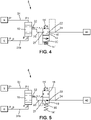
- Figures 4 and 5 are a schematic representation of a second embodiment.
- the isolation device 8 comprises a select low valv e 18 and an electromagnetic isolation valve 19 ,
- the select low valve 18 is upstream from the isolation valve 19.
- the select low valve 18 and the isolation valve 19 are in this embodiment separated components. Each component has its own housing.
- the select low valve 18 has two inlet ports 31, 31b and one outlet port 32.
- the first inlet port 31 permanently receives the first air control pressure P1.
- the second inlet port 31b permanently receives the second air pressure P_p, i.e the parking brake chamber 6 pressure.
- An internal plunger can slide an housing of the select low valve 18, under the opposite effects of the pressure in the first internal port 31 and the pressure in the second internal port 31b. Resulting outlet pressure in port 32 is the lowest of the two pressures P1, P_p.
- the electromagnetic isolation valve 19 comprises an inlet port 21, an outlet port 22, a return spring 14, an electromagnet 15, a first internal control port 23, and a second internal control port 24.
- the plunger 16 can slide in a housing between a first extreme position and a second extreme position. In the first extreme position, figure 4 , the plunger 16 prevents fluidic communication between inlet port 21 and outlet port 22 because both inlet port 21 and outlet 22 are sealed, because they are facing a wall of the plunger 16. In the second extreme position, figure 5 , the plunger 16 allows fluidic communication between the inlet port 21 and the outlet port 22, because both inlet port 21 and outlet port 22 are facing an internal duct 30 of the plunger. Only the first extreme position and the second extreme position are steady state positions.
- first internal control port 23 is in permanent fluidic communication with the inlet port 21. Therefore, pressure in the first internal control port 23 is equal to the pressure at the outlet of the select low valve 18, therefore the minimum between P1 and P_p.
- Second internal control port 24 is in permanent fluidic communication with outlet port 22. Outlet port 22 connected to regulation unit 40. Plunger 16 can slide in the housing under the combined forces applied by the electromagnet 15, the return spring 14, the pressure in the first internal control port 23, and the pressure in the second external control port 24.
- the magnetic properties of the electromagnet 15, the mechanical properties of the return spring 14 and the surfaces acting of the plunger 16 are chosen so that when the electromagnet 15 is energized, the force applied by the electromagnet 15 is always higher that the combined forces applied by the return spring 14 and the various pressure in the internal control ports 23 and 24.
- P1 pressure is not transmitted to the regulation unit 40, therefore anti-compounding function is provided.
- pressure P_p in parking brake chamber 6 is close to 8 bar, which is higher than P1 pressure. Therefore, when driver requires brakes application, the output pressure of the select low valve is P1 pressure.
- the internal control port 23 receives P1 pressure and moves the plunger 16 in the second extreme position in which outlet port 22 communicates with inlet port 21, as represented on figure 5 . In this case, P1 pressure is transmitted to regulation unit 40, therefore service brakes are applied as expected. Vehicle braking is provided by the pneumatic back-up line.
- Figures 6, 7 and 8 are a schematic representation of a third embodiment.
- the isolation device 8 comprises a pneumatic isolation valve 20 and an electromagnetic isolation valve 19,
- the electromagnetic isolation valve 19 operates in the same way as the second embodiment and will not be described again.
- the pneumatic isolation valve 20 is upstream from the electromagnetic isolation valve 19.
- the pneumatic isolation valve 20 comprises an inlet port 41, an outlet port 42, a return spring 14, an internal control port 43, an auxiliary port 44 and a mobile plunger 16'.
- the plunger 16' can slide in a housing between a first extreme position and a second extreme position. In the second extreme position, represented on figure 8 , the plunger 16 allows fluidic communication between inlet port 41 and outlet port 42 because both inlet port 41 and outlet port 42 are aligned with an internal duct 30' of the plunger 16'. In the first extreme position, represented on figures 6 and 7 , the plunger 16' prevents fluidic communication between the inlet port 41 and the outlet port 42. Outlet port 42 is in communication with auxiliary port 44 which is connected to the atmospheric pressure Patm.
- Inlet port 41 is facing an internal duct of the plunger 16' and is sealed. Plunger 16' can slide in its housing under combined actions of return spring and of the pressure applied in the control port 43. Return spring and pressure in the control port 43 have opposite effects. Control port 43 receives pressure P_p from the parking brake chamber 6. When the pressure in the control port 43 is high enough, i.e higher than a threshold, the action of this pressure on a surface of the plunger overcomes the force embodied by the return spring and the plunger can move to the position in which inlet port 41 and outlet port 42 are in fluidic communication. Therefore, air control pressure P1 is transmitted to the electromagnetic isolation valve 19, as represented on figure 8 .
- Isolation device 8 can be disposed in the layout of the pneumatic braking system 100 in different locations, while still operating in the same way.
- the isolation device 8 is included in the electro pneumatic modulator unit 2. It should be understood that the isolation device 8 and the electro pneumatic modulator unit 2 are in such a case contained in a common housing.
- the isolation device 8 is included in a foot brake modulator 9, the foot brake modulator 9 being configured for delivering the first air control pressure P1 and being a separated unit from the electro pneumatic modulator unit 2.
- the operation remains identical, only the mechanical integration of the isolation device 8 is different.
- the isolation device 8 is separated from electro pneumatic modulator unit 2 and separated from the foot brake modulator 9.
- the operation of the isolation device remains identical and only its mechanical integration in the vehicle differs.
- the isolation device 8 is disposed upstream from the electro pneumatic modulator unit 2.
- Outlet port of the isolation device 8 is in fluidic communication with one inlet port of electro pneumatic modulator unit 2.
- the parking brake chamber 6 pressure first threshold Th_1 for allowing or preventing the delivery of the first air control pressure P1 to the regulation unit 40 is comprised between 3,5 Bar and 4,5 Bar.
- the second predetermined threshold Th_2 is comprised between 3 and 4 Bar, and the third predetermined threshold Th_3 is comprised between 2 and 2,8 Bar.
- the parking brake unit 7 comprises an electronic control unit configured for delivering the second modulated air pressure P_p to the parking brake pneumatic chamber 6.
- Figure 11 illustrates another embodiment, with a pneumatic braking system compatible with two separate axles.
- the pneumatic braking system 100 further comprises:
- the same isolation device 8 can control the delivery and the prevention of the delivery of the first air control pressure P1 to both the first regulation unit 40 and the second regulation unit 40'.
- a single isolation device 8 can be used for both axles, which simplifies the braking system.
- isolation unit 8 can be connected either to the parking brake chamber 6 of the first axle or to the parking brake chamber 6' of the second axle.
- isolation unit 8 is connected to the parking brake chamber 6 of the first axle. To simplify figure 11 , parking brake supply lines have not been represented.
- the isolation device 8 is included in the electro pneumatic modulator unit 2.
- Figure 12 represents another embodiment compatible with three separate axles.
- a braking assembly system 120 is represented on figure 12 .
- the so called 'first pneumatic braking system' is the pneumatic braking system as described above.
- the braking system assembly 120 comprises :
- the first pneumatic braking system 100 mentioned above is a pneumatic braking system as described earlier in the specification.
- the second pneumatic braking system 100' is a pneumatic braking system as described earlier in the specification.
- second pneumatic braking system 100' deals with two axles. Each axle is equipped in a similar way; with respectively isolation device 40', 40", service brake actuator 1',1", parking brake 4', 4", service brake chamber 3', 3", parking brake chamber 6', 6".
- the second stage 52 of the foot brake modulator 9 delivers the first air control pressure P1 representative of a vehicle driver's braking request to the isolation device 8'.
- the isolation device 8' cooperates with both isolation device 40' and isolation device 40".
Abstract
Description
- This disclosure relates to vehicle braking systems with a compound management function. It relates in particular to electronically control pneumatic braking systems for heavy duty vehicles like trucks, buses, off-highway vehicles.
- It is known to provide electronic anti-compounding function. Such function is disclosed for example in application
WO 2020/228963 Electronic anti-compounding function operates when vehicle is operated in regular conditions, which means when all electronic systems are electrically powered-up, and without any electrical fault present in the braking system. - When electrical systems are switched-off, or not electrically powered, electronic anti-compounding function is not active. In such a case, anti-compounding function has to be provided in a different way.
- A goal of the present invention is to provide a solution in which anti-compounding function is performed throughout the use cases of the vehicle. In particular, anti-compounding should be available even when electronic systems are not powered-up.
- At the same time, proposed solution should allow electronic anti-compounding function to still be active when electronic systems are used in nominal mode, which is powered-up and with no fault present.
- Proposed solution is based on a new concept of isolation valve provided on the pneumatic back-up line of the braking system.
- It is proposed a pneumatic braking system for an axle of a vehicle, comprising:
- a. a service brake actuator configured for applying a braking force to an axle of the vehicle,
- b. an electro pneumatic modulator unit configured for:
- i. Receiving a first air control pressure representative of a vehicle driver's braking request,
- ii. Receiving an air supply pressure, and
- iii. Delivering a first modulated air pressure to a service brake chamber to control the braking force applied by the service brake actuator, the first modulated air pressure being delivered by a regulation unit,
- c. a parking brake actuator, configured for applying a braking force under the action of an elastic spring and of a pneumatic chamber, the pneumatic chamber being configured for applying a force opposed to the force applied by the spring,
- d. a parking brake unit, configured for delivering a second air pressure to the parking brake pneumatic chamber to control the braking force applied by the parking brake actuator,
- e. an isolation device configured for:
- i. in a first mode in which the isolation device is electrically energized, preventing the delivery of the first air control pressure to the regulation unit, and
- ii. in a second mode in which the isolation device is not electrically energized:
- 1. allowing the delivery of the first air control pressure to the regulation unit so that a braking force is applied by the service brake actuator when the pressure in the parking brake chamber is higher than a first predetermined threshold, and
- 2. preventing the delivery of the first air control pressure to the regulation unit when the pressure in the parking brake chamber is lower than or equal to the first predetermined threshold.
- Thanks to the features of the isolation device, the first air control pressure is delivered to the regulation unit only when the pressure in the parking brake chamber is high enough, i.e higher than a first predetermined threshold. This high pressure in the parking brake chamber can exist only if the parking brake is released. In other words, service brakes can be activated only if parking brake is released. Anti-compounding function is achieved without any need to have the electronic systems energized. This gives the advantage that even in particular use cases during which some electronic systems of the truck are disconnected, like for example during vehicle servicing in a workshop, service brakes can only be applied by a mechanic while parking brake is already released. Reliability issues associated with brake compounding are avoided.
- According to one aspect of the disclosure, when the isolation device is electrically energized, the electro pneumatic modulator unit is configured for delivering a first modulated air pressure to the service brake chamber, the first modulated air pressure being controlled only by the regulation unit in response to electrical control signals.
- According to one aspect, the electrical control signals are sent by an ecu braking system.
- The following features, can be optionally implemented, separately or in combination one with the others:
- According to an embodiment of the pneumatic braking system, the isolation device comprises an on-off solenoid valve, the on-off solenoid valve comprising :
- a. - an inlet port ,
- b. - an outlet port,
- c - a control port,
- d - a return spring,
- e - an electromagnet,
- f - a plunger, configured for moving under the joined action of the electromagnet, of the return spring and of a pressure in the control port, to selectively allow or prevent fluidic communication between the inlet port and the outlet port,
- i. allowing fluidic communication between the inlet port and the outlet port when the electromagnet is not electrically energized and the pressure in the control port is higher than the first predetermined threshold, and
- ii. preventing fluidic communication between inlet port and outlet port:
- 1. when the electromagnet is electrically energized or
- 2. when the electromagnet is not electrically energized and the pressure in the inlet port is higher than a second predetermined threshold and the pressure in the control port is lower than a third predetermined threshold,
in which the first air control pressure is fluidically connected to the inlet port of the on-off solenoid valve, in which the outlet port of the on-off solenoid valve is fluidically connected to the regulation unit, and in which the control port is fluidically connected to the parking brake pneumatic chamber.
- According to another embodiment of the pneumatic braking system, the isolation device comprises a select low valve and an electromagnetic isolation valve,
- a. the electromagnetic isolation valve comprising an inlet port and an outlet port, and being configured for allowing fluidic communication between the inlet port and the outlet port when the electromagnetic isolation valve is not electrically energized and for preventing fluidic communication between the inlet port and the outlet port when the electromagnetic isolation valve is electrically energized,
- b. the select low valve comprising a first inlet port connected to the first air control pressure, a second inlet port connected to the parking brake pneumatic chamber having a second air pressure, and an outlet port,
the select low valve being configured so that an outlet port pressure is equal to the lowest of the first pressure and second air pressure,
the outlet port of the select low valve is connected to the inlet port of the electromagnetic isolation valve,
and the outlet port of the electromagnetic isolation valve is configured for being in fluidic communication with the regulation unit. - According to another embodiment of the pneumatic braking system, the isolation device comprises a pneumatic isolation valve and an electromagnetic isolation valve,
- a. the pneumatic isolation valve comprising a control port, an inlet port, an outlet port, the first air control pressure being fluidically connected to the inlet port, the control port being fluidically connected to the parking brake pneumatic chamber,
the pneumatic isolation valve being configured for:- i. allowing fluidic communication between the inlet port and the outlet port if pressure in the control port is higher than the first predetermined threshold, and
- ii. preventing fluidic communication between the inlet port and the outlet port if pressure in the control port is lower than or equal to the first predetermined threshold, and
- iii. allowing fluidic communication between the outlet port and atmosphere if pressure in the control port is lower than or equal to the first predetermined threshold,
- b. the electromagnetic isolation valve comprising an inlet port and an outlet port, and being configured for:
- i. allowing fluidic communication between the inlet port and the outlet port when the electromagnetic isolation valve is not electrically energized and,
- ii. preventing fluidic communication between inlet port and outlet port when the electromagnetic isolation valve is electrically energized,
in which the outlet port of the electromagnetic isolation valve is configured for being in fluidic communication with the regulation unit. - According to one embodiment, the isolation device is included in the electro pneumatic modulator unit.
- According to another embodiment, the isolation device is included in a foot brake modulator, the foot brake modulator being configured for delivering the first air control pressure and being a separated unit from the electro pneumatic modulator unit.
- According to yet another embodiment, the isolation device is separated from electro pneumatic modulator unit and separated from the foot brake modulator.
- According to one aspect of the pneumatic braking system, the parking brake chamber pressure first threshold for allowing or preventing the delivery of the first air control pressure to the regulation unit is comprised between 3,5 Bar and 4,5 Bar.
- According to one aspect, the second predetermined threshold is comprised between 3 and 4 Bar, and the third predetermined threshold is comprised between 2 and 2,8 Bar.
- According of one example of implementation of the pneumatic braking system, the parking brake unit comprises an electronic control unit configured for delivering the second modulated air pressure to the parking brake pneumatic chamber.
- According of one example of implementation, the pneumatic braking system further comprises:
- a.- a second service brake actuator configured for applying a braking force to a second axle of the vehicle,
- b.- a second electro pneumatic modulator unit configured for:
- i. Receiving the first air control pressure representative of a vehicle driver's braking request,
- ...ii. Receiving the air supply pressure, and
- ...iii. Delivering a second modulated air pressure to a second service brake chamber to control the braking force applied by the second service brake actuator, the second modulated air pressure being delivered by a second regulation unit,
- in a first mode in which the isolation device is electrically energized, preventing the delivery of the first air control pressure to the second regulation unit,
- in a second mode in which the isolation device is not electrically energized:
- -- allowing the delivery of the first air control pressure to the second regulation unit when the pressure in the parking brake chamber is higher than a first predetermined threshold, and
- -- preventing the delivery of the first air control pressure to the second regulation unit when the pressure in the parking brake chamber is lower than or equal to the first predetermined threshold.
- According to an embodiment, the isolation device is included in the electro pneumatic modulator unit.
- The invention also relates to a braking system assembly, comprising :
- a. a first pneumatic braking system as previously described, the first pneumatic braking system cooperating with a first axle of the vehicle, and comprising
- b. a second pneumatic braking system as previously described, the second pneumatic braking system cooperating with a second axle of the vehicle,
- The invention relates as well to a commercial vehicle comprising a pneumatic braking system as previously described or comprising a braking system assembly as previously described.
- Other features, details and advantages of the invention will appear from the following detailed description of three of its embodiments, given by way of non-limiting example, and with reference to the accompanying drawings, in which:
-
Fig. 1 is a schematic view of the general architecture of a pneumatic braking system according to an embodiment of the invention, -
Fig. 2 is a schematic view of a first embodiment of an isolation device, in a first operating mode, -
Fig. 3 is a schematic view of the first embodiment of the isolation device, in a different operating mode, -
Fig. 4 is a schematic view of a second embodiment of the isolation device, in a first operating mode, -
Fig. 5 is a schematic view of the second embodiment of the isolation device, in a different operating mode, -
Fig. 6 is a schematic view of a third embodiment of the isolation device, in a first operating mode, -
Fig. 7 is a schematic view of the third embodiment of the isolation device, in a different operating mode, -
Fig. 8 is a schematic view of the third embodiment of the isolation device, in a second different operating mode, -
Fig. 9 is a schematic view of a braking actuator used by the pneumatic braking system, -
Fig. 10 is another schematic view of a detail of the pneumatic braking system, -
Fig. 11 is a schematic view of another embodiment of the pneumatic braking system. -
Fig. 12 is a schematic view of another embodiment of the pneumatic braking system. -
Fig. 13 is a schematic view of yet another embodiment of the pneumatic braking system. -
Fig. 14 is a general view of a truck with a pneumatic braking system according to the disclosure. -
Figure 14 illustrates in a non-limiting manner atruck 150 with three axles, afront steering axle 61 and tworear axles truck 150 comprises apneumatic braking system 100. - The truck considered here can be the tractor unit in a tractor/trailer configuration. It can also be a utility 'carrier' truck. The proposed configuration is also valid for any kind of heavy-duty vehicles, including buses and construction vehicles.
-
Figure 1 is a schematic of the layout of thebraking system 100. Only the most relevant components have been represented. Plain lines represent pneumatic lines supplying delivery pressure to the various air brakes actuators. Dotted lines represent pneumatic lines supplying control pressure to the devices that control the operation of the brake actuators. -
Braking system 100 comprises a central brakingelectronic control unit 20. This central braking unit manages the operation of thebraking system 100. It includes anelectro pneumatic modulator 2, afoot brake modulator 9, aparking brake unit 7, one or severalservice brake actuators 1, one or severalparking brake actuators 4. Thebraking system 100 of the truck comprises a service brake and a parking brake. - The service brake is configured to apply a braking effort on an axle of the vehicle when the vehicle is rolling. The service brake is controlled by the driver by his foot pressure on a brake pedal. The parking brake is configured to apply a braking effort on an axle of the vehicle when the vehicle is parked.
- Vehicle driver's braking request is delivered by a
foot brake modulator 9.Foot brake modulator 9 delivers a first air control pressure P1 that increases when the drivers increases his effort on the brake pedal of the vehicle. - The
electro pneumatic modulator 2 receives an air supply pressure P_R and delivers a modulated air pressure P_s to theservice brake actuators 1. Electropneumatic modulator unit 2 is configured to control wheel speed deceleration. It therefore ensures wheels anti-lock function and is part of the stability control function of the vehicle. Electropneumatic modulator unit 2 is configured to receive braking requests from the centralelectronic control unit 20. In this example, electropneumatic modulator unit 2 is configured to communicate with centralelectronic control unit 20 by digital communication protocol. CAN protocol can for example be implemented. The various electronic systems are connected to an electrical harness. Electrical power is provided by a battery which is charged by an alternator for trucks with internal combustion engines. - The air supply pressure P_R is provided by a
service brake reservoir 26.Service brake reservoir 26 is supplied in compressed air by anair compressor 28 which compresses atmospheric air and increases its pressure above atmospheric pressure. Pressure in theservice brake reservoir 26 is controlled by a regulation unit which has not been represented, so called governor. Nominal reservoir pressure is for example 8 bar. - In the illustrated example, the
parking brake unit 7 is configured for receiving a second supply air pressure P_R2. Second supply air pressure is delivered by a second air reservoir which isparking brake reservoir 27. - Driver's service braking requests are interpreted by the system from the position of the brake pedal in the
foot brake modulator 2. Brake pedal position is monitored by redundant position sensors. The pedal position information is used by the central braking ecu to control the various actuators in order to achieve the driver request. Other systems like anti-locking or stability control may override driver's request. - In parallel of the electrical signal, a first air control pressure P1, representative of a vehicle driver's braking request, is delivered by a
foot brake modulator 9. First air control pressure P1 increases when a depression applied by the vehicle driver on the brake pedal increases. - The parking brake is configured to have only two stable operation modes: a first mode in which the parking brake is released, a second mode in which the parking brake is activated with nominal braking force. The parking brake can be activated or released by the driver by pulling a lever, or knob.
-
Figure 10 describes schematically theelectro pneumatic modulator 2. - The modulated air pressure P_s is obtained by modulation of the air supply pressure P_R and atmospheric pressure. In other words, modulated air pressure P_s is inferior or equal to air supply pressure P_R. For this, the
electro pneumatic modulator 2 comprises arelay valve 37 and twoelectrovalves service brake chambers 3. This pressure can be continuously adjusted between the supply pressure P_R and the atmospheric pressure Patm. Pulse width modulation control of the twoelectrovalves - In case electronic control is not active, either because of a fault in the system or because not all the elements of the system have been assembled, electrovalves 35 and 36 are not electrically powered-up and remain in shut-off position.
Relay valve 37 receives the first air control pressure P1. P1 pressure may control the relay valve so that the supply pressure P_R is delivered to theservice brake chamber 3. -
Figure 9 describes a brake actuator integrated in thepneumatic brake system 100. - The actuator has the general shape of a cylinder having an axis X1. This cylinder forms an enclosure having two
chambers actuation rod 25 protudes from the housing. Onechamber 3 is dedicated to the service brake and thesecond chamber 6 is dedicated to the parking brake. - The
service brake chamber 3 has a firstmobile piston 3a that can reciprocate in a first sealed cavity. Thefirst piston 3a and theactuation rod 25 are rigidly connected together. Pressure applied in theservice brake chamber 3 moves the firstmobile piston 3a and theactuation rod 25 in a first direction. Theactuation rod 25 in turn activates a mechanism, not represented, that pushes the brake shoes against the brake drums, or that pushes brake pads against brake disk. Braking force is thus generated on the axle. - The
parking brake chamber 6 has a secondmobile piston 6a that can reciprocate in a second cavity sealed by a second mobile membrane. The first 3a and second 6a pistons are coaxial. Aninternal rod 6b is rigidly connected to thesecond piston 6a. Apreloaded spring 5 is compressed between the housing and the secondmobile piston 6a.Preloaded spring 5 tends to push thesecond piston 6a in the first direction, against thefirst piston 3a. Pressure applied in theparking brake chamber 6 pushes back thesecond piston 6a in the opposite direction. This pressure tends to compress thespring 5 and to move thesecond piston 6a apart from thefirst piston 3a and therefore to release the effort on theactuation rod 25. - When no pressure is applied in the
parking brake chamber 6, thesecond piston 6a is pushed by thepreloaded spring 5 and theinternal rod 6b against thefirst piston 3a and push it. Consequently, theactuation rod 25 is pushed and braking effort is applied. - When pressure is applied in the
parking brake chamber 6, the second piston is retracted and leaves thefirst piston 3a and theactuation rod 25 free to move under the action of the pressure in theservice brake chamber 6. - In case pressure in the
service brake chamber 3 is applied while parking brake is already activated, the efforts of the twomobile pistons rod 25 can become excessive for the brake shoe mechanism. This sequence is called brake compounding and is well known to be an issue for the reliability of the brakes. The main goal of the current disclosure is to propose a solution that can provide anti-compounding function in particular use cases that were not properly adressed by the prior art. - In the present disclosure, an electrical component or subsystem is said to be energized when it is supplied with electrical power.
- The
pneumatic braking system 100 for an axle of a vehicle, comprises: - a. a
service brake actuator 1 configured for applying a braking force to an axle of the vehicle, - b. an electro
pneumatic modulator unit 2 configured for:- i. Receiving a first air control pressure P1 representative of a vehicle driver's braking request,
- ii. Receiving an air supply pressure P_R, and
- iii. Delivering a first modulated air pressure P_s to a
service brake chamber 3 to control the braking force applied by theservice brake actuator 1, the first modulated air pressure P_s being delivered by aregulation unit 40,
- c. a
parking brake actuator 4, configured for applying a braking force under the action of anelastic spring 5 and of apneumatic chamber 6, the pneumatic chamber being configured for applying a force opposed to the force applied by thespring 5, - d. a
parking brake unit 7, configured for delivering a second air pressure P_p to the parking brakepneumatic chamber 6 to control the braking force applied by theparking brake actuator 4, - e. an
isolation device 8 configured for:- i. in a first mode in which the
isolation device 8 is electrically energized, preventing the delivery of the first air control pressure P1 to theregulation unit 40, and - ii. in a second mode in which the
isolation device 8 is not electrically energized:- 1. allowing the delivery of the first air control pressure P1 to the
regulation unit 40 so that a braking force is applied by the service brake actuator when the pressure in theparking brake chamber 6 is higher than a first predetermined threshold Th_1, and - 2. preventing the delivery of the first air control pressure P1 to the
regulation unit 40 when the pressure in theparking brake chamber 6 is lower than or equal to the first predetermined threshold Th_1.
- 1. allowing the delivery of the first air control pressure P1 to the
- i. in a first mode in which the
- The braking force of the service brake is applied by the
service brake actuator 1. The level of braking force delivered by the service brake is controlled by the pressure unservice brake chamber 3. As illustrated onfigure 9 , therod 25 acts on the brake calipers to generate braking force on the related wheel of the axle. - Thanks to the features of the
isolation device 8, the first air control pressure is delivered to theregulation unit 40 only when the pressure P_p in theparking brake chamber 6 is high enough, i.e higher than a first predetermined threshold Th_1. This high pressure in theparking brake chamber 6 can exist only if the parking brake is released. In other words, service brakes can be activated only if parking brake is released. Anti-compounding function is achieved without any need to have the electronic systems energized. This gives the advantage that even in particular use cases during which some electronic systems of the truck are disconnected, like for example during vehicle servicing in a workshop. Service brakes service brakes can only be applied by a mechanic while parking brake is in the released state. Reliability issues associated with brake compounding are avoided. - Allowing the delivery of the first air control pressure P1 to the
regulation unit 40 means that the first air control pressure P1 is received by a fluidic port of theregulation unit 40. - When the
isolation device 8 is electrically energized, the electropneumatic modulator unit 2 is configured for delivering a first modulated air pressure P_s to theservice brake chamber 3, the first modulated air pressure P_s being controlled only by theregulation unit 40 in response to electrical control signals. The electrical control signals are sent by ecu braking system. - In the first operation mode in which the
isolation device 8 is electrically energized, the delivery of the first air control pressure P1 to theregulation unit 40 is prevented. In other words, in this first mode, the first air control pressure P1 is isolated from theservice brake chamber 3. First air control pressure P1 has thus no effect on theregulation unit 40, and therefore has no effect either on theservice brake actuator 1. This mode is the normal mode when all electronic systems are operating in a nominal way, i.e a fully functional state in which there's no electrical fault found by the on-board diagnostic system. - In this first operation mode, the anti-compounding function is performed by the electronic anti-compounding control strategy. Pressure in the
service brake chamber 3 is managed by thepressure regulation device 40. Theregulation unit 40 receives in this case an air pressure supply coming directly from theservice brake reservoir 26.Regulation unit 40 comprises twoelectrovalves relay valve 37. Each valve can be selectively opened or closed, so that the pressure P_s delivered by theregulation unit 40 to theservice brake chamber 3 can be adjusted to a set-point value. The pressure set-point value is provided by the central braking ecu. Set-point value depends on driver's request and actual wheel deceleration, so that wheel anti-lock function is active. - In the second operation mode, electronic anti-compounding control strategy is not relied upon, and anti-compounding function is provided by the back-up pneumatic line, using first air control pressure P1.
- Three different embodiments of the general concept will be described.
-
Figures 2 and 3 are a schematic representation of a first embodiment. According to this first embodiment of thepneumatic braking system 100, theisolation device 8 comprises an on-offsolenoid valve 17, the on-offsolenoid valve 17 comprises : - a. - an
inlet port 11, - b. - an
outlet port 12, - c - a
control port 13, - d - a
return spring 14, - e - an
electromagnet 15, - f - a
plunger 16, configured for moving under the joined action of the electromagnet, of thereturn spring 14 and of a pressure in thecontrol port 13, to selectively allow or prevent fluidic communication between theinlet port 11 and theoutlet port 13, - i. allowing fluidic communication between the
inlet port 11 and theoutlet port 12 when theelectromagnet 15 is not electrically energized and the pressure in thecontrol port 13 is higher than the first predetermined threshold Th_1, and - ii. preventing fluidic communication between
inlet port 11 and outlet port 12:- 1. when the
electromagnet 15 is electrically energized or - 2. when the
electromagnet 15 is not electrically energized and the pressure in theinlet port 11 is higher than a second predetermined threshold Th_2 and the pressure in thecontrol port 13 is lower than a third predetermined threshold Th_3,
- 1. when the
- Throughout the description, the expression "is fluidically connected to" means "in permanent fluidic communication with".
- The on-off
solenoid valve 17 comprises aninlet port 11, anoutlet port 12, acontrol port 13, areturn spring 14, anelectromagnet 15, a firstinternal control port 13a, and a secondinternal control port 13b. Theplunger 16 can slide in a housing between a first extreme position and a second extreme position. In the first extreme position,figure 2 , theplunger 16 prevents fluidic communication betweeninlet port 11 andoutlet port 12. Bothinlet port 11 andoutlet 12 are sealed, because they are facing a wall of theplunger 16. In the second extreme position,figure 3 , theplunger 16 allows fluidic communication between theinlet port 11 and theoutlet port 12, because bothinlet port 11 andoutlet port 12 are facing aninternal duct 30 of the plunger. Only the first extreme position and the second extreme position are steady state positions. Intermediate positions between the first extreme position and the second extreme position are only transient positions that theplunger 16 can go through during the transitions between the first and the second extreme positions. - First
internal control port 13a in in permanent fluidic communication withinlet port 11. Therefore, pressure in the firstinternal control port 13a is equal to P1 pressure. Secondinternal control port 13b is in permanent fluidic communication with theoutlet port 12.Outlet port 12 is fluidically connected toregulation unit 40.
Plunger 16 can slide in the housing under the combined forces applied on it by theelectromagnet 15, by thereturn spring 14, by the pressure in thecontrol port 13, by the pressure in the firstinternal control port 13a, and by the pressure in the secondexternal control port 13b.
Return spring 14 and pressure in thecontrol port 13 both tend to push theplunger 16 in a first direction, towards second extreme position. Theelectromagnet 15, the pressure in the firstinternal control port 13a, and the pressure in the secondexternal control port 13b all tend to push theplunger 16 in the opposite direction, towards the first extreme position.
The magnetic properties of theelectromagnet 15, the mechanical properties of thereturn spring 14 and the surface area acting of theplunger 16 are chosen so that when theelectromagnet 15 is energized, the force applied by theelectromagnet 15 is always higher that the combined forces applied by thereturn spring 14 and the various pressure in thedifferent control ports - Therefore, when the
electromagnet 15 is energized, it pushes theplunger 16 so that theplunger 16 is in the first extreme position, which is the position represented onfigure 2 . - When the
electromagnet 15 is not energized, the position of theplunger 16 is the result of the balance of the forces ofreturn spring 14, the pressure in thecontrol port 13, and the pressure in the twointernal control ports
When the pressure in theinlet port 11 is high enough, ie higher than a second predetermined threshold Th_2 and at the same time the pressure in thecontrol port 13 is low enough, i.e lower than a third predetermined threshold Th_3, theplunger 16 is pushed in the first extreme position as onfigure 2 , in which theinlet port 11 andoutlet port 12 are blanked-off. This means that service brakes can't be applied when parking brakes are applied. Anti-compounding function is provided.
Still when theelectromagnet 15 is not electrically energized, when pressure in thecontrol port 13 is high enough, i.e higher than the first predetermined threshold Th_1, theplunger 16 is pushed in the second extreme position, as onfigure 3 . In this position of theplunger 16, fluidic communication between theinlet port 11 and theoutlet port 12 is allowed. This means that when parking brake is released, P1 control pressure is transmitted to theregulation unit 40 so that service brakes are applied. -
Figures 4 and 5 are a schematic representation of a second embodiment. In this embodiment, theisolation device 8 comprises a selectlow valv e 18 and anelectromagnetic isolation valve 19, - a. the
electromagnetic isolation valve 19 comprising aninlet port 21 and anoutlet port 22, and being configured for allowing fluidic communication between theinlet port 21 and theoutlet port 22 when theelectromagnetic isolation valve 19 is not electrically energized and for preventing fluidic communication between theinlet port 21 and theoutlet port 22 when the electromagnetic isolation valve is electrically energized, - b. the select
low valve 18 comprising afirst inlet port 31 connected to the first air control pressure P1, asecond inlet port 31b connected to the parking brakepneumatic chamber 6 having a second air pressure P_p, and anoutlet port 32, - The select
low valve 18 is upstream from theisolation valve 19. The selectlow valve 18 and theisolation valve 19 are in this embodiment separated components. Each component has its own housing. - The select
low valve 18 has twoinlet ports outlet port 32. Thefirst inlet port 31 permanently receives the first air control pressure P1. Thesecond inlet port 31b permanently receives the second air pressure P_p, i.e theparking brake chamber 6 pressure. An internal plunger can slide an housing of the selectlow valve 18, under the opposite effects of the pressure in the firstinternal port 31 and the pressure in the secondinternal port 31b. Resulting outlet pressure inport 32 is the lowest of the two pressures P1, P_p. - The
electromagnetic isolation valve 19 comprises aninlet port 21, anoutlet port 22, areturn spring 14, anelectromagnet 15, a firstinternal control port 23, and a secondinternal control port 24. Theplunger 16 can slide in a housing between a first extreme position and a second extreme position. In the first extreme position,figure 4 , theplunger 16 prevents fluidic communication betweeninlet port 21 andoutlet port 22 because bothinlet port 21 andoutlet 22 are sealed, because they are facing a wall of theplunger 16. In the second extreme position,figure 5 , theplunger 16 allows fluidic communication between theinlet port 21 and theoutlet port 22, because bothinlet port 21 andoutlet port 22 are facing aninternal duct 30 of the plunger. Only the first extreme position and the second extreme position are steady state positions. Intermediate position between the first extreme position and the second extreme position are only transient positions that the plunger can take during the transitions between first and second extreme positions.
As schematically represented onfigures 4 and 5 , the firstinternal control port 23 is in permanent fluidic communication with theinlet port 21. Therefore, pressure in the firstinternal control port 23 is equal to the pressure at the outlet of the selectlow valve 18, therefore the minimum between P1 and P_p. Secondinternal control port 24 is in permanent fluidic communication withoutlet port 22.Outlet port 22 connected toregulation unit 40.
Plunger 16 can slide in the housing under the combined forces applied by theelectromagnet 15, thereturn spring 14, the pressure in the firstinternal control port 23, and the pressure in the secondexternal control port 24.
Return spring 14 and pressure in the firstinternal control port 23 both tend to push theplunger 16 in a first direction, towards first extreme position. Theelectromagnet 15, and the pressure in the secondinternal control port 24 both tend to push theplunger 16 in the opposite direction, towards second extreme position.
The magnetic properties of theelectromagnet 15, the mechanical properties of thereturn spring 14 and the surfaces acting of theplunger 16 are chosen so that when theelectromagnet 15 is energized, the force applied by theelectromagnet 15 is always higher that the combined forces applied by thereturn spring 14 and the various pressure in theinternal control ports - Therefore, when the
electromagnet 15 is energized, it pushes theplunger 16 so that the plunger is in the first extreme position and pressure delivery toregulation unit 40 is prevented. This mode is represented onfigure 4 . - When the
electromagnet 15 is not energized, the position of theplunger 16 is the result of the balance of the forces ofreturn spring 14, the pressure in the firstinternal control port 23, and the pressure in the secondinternal control port 24.
When theelectromagnet 15 is not active and parking brake is applied, pressure P_p inparking brake chamber 6 is close to atmospheric pressure. Therefore, when braking brakes are applied, P1 is not transmitted since the output of the selectlow valve 18 will be P_p, which is lower than P1. In turn, pressure of theinternal control port 23 is close to atmospheric pressure. Without the effect of internal port pressure to lift theplunger 16, the plunger remains in the position in whichoutlet port 22 is isolated frominlet port 21, as represented onfigure 4 . P1 pressure is not transmitted to theregulation unit 40, therefore anti-compounding function is provided.
Whenelectromagnet 15 is not active and parking brake is released, pressure P_p inparking brake chamber 6 is close to 8 bar, which is higher than P1 pressure. Therefore, when driver requires brakes application, the output pressure of the select low valve is P1 pressure. Theinternal control port 23 receives P1 pressure and moves theplunger 16 in the second extreme position in whichoutlet port 22 communicates withinlet port 21, as represented onfigure 5 . In this case, P1 pressure is transmitted toregulation unit 40, therefore service brakes are applied as expected. Vehicle braking is provided by the pneumatic back-up line. -
Figures 6, 7 and8 are a schematic representation of a third embodiment. According to this third embodiment of the pneumatic braking system, theisolation device 8 comprises apneumatic isolation valve 20 and anelectromagnetic isolation valve 19, - a. the
pneumatic isolation valve 20 comprising acontrol port 43, aninlet port 41, anoutlet port 42, the first air control pressure P1 being fluidically connected to theinlet port 11, thecontrol port 43 being fluidically connected to the parking brakepneumatic chamber 6,
thepneumatic isolation valve 20 being configured for:- i. allowing fluidic communication between the
inlet port 41 and theoutlet port 42 if pressure in thecontrol port 43 is higher than the first predetermined threshold Th_1, and - ii. preventing fluidic communication between the
inlet port 41 and theoutlet port 42 if pressure in thecontrol port 43 is lower than or equal to the first predetermined threshold Th_1, and - iii. allowing fluidic communication between the
outlet port 42 and atmosphere if pressure in thecontrol port 43 is lower than or equal to the first predetermined threshold Th_1,
- i. allowing fluidic communication between the
- b. the
electromagnetic isolation valve 19 comprising aninlet port 21 and anoutlet port 22, and being configured for:- i. allowing fluidic communication between the
inlet port 21 and theoutlet port 22 when theelectromagnetic isolation valve 19 is not electrically energized and, - ii. preventing fluidic communication between
inlet port 21 andoutlet port 22 when theelectromagnetic isolation valve 19 is electrically energized,
- i. allowing fluidic communication between the
- In this third embodiment, the
electromagnetic isolation valve 19 operates in the same way as the second embodiment and will not be described again. Thepneumatic isolation valve 20 is upstream from theelectromagnetic isolation valve 19. - The
pneumatic isolation valve 20 comprises aninlet port 41, anoutlet port 42, areturn spring 14, aninternal control port 43, anauxiliary port 44 and a mobile plunger 16'. The plunger 16' can slide in a housing between a first extreme position and a second extreme position. In the second extreme position, represented onfigure 8 , theplunger 16 allows fluidic communication betweeninlet port 41 andoutlet port 42 because bothinlet port 41 andoutlet port 42 are aligned with an internal duct 30' of the plunger 16'. In the first extreme position, represented onfigures 6 and 7 , the plunger 16' prevents fluidic communication between theinlet port 41 and theoutlet port 42.Outlet port 42 is in communication withauxiliary port 44 which is connected to the atmospheric pressure Patm.Inlet port 41 is facing an internal duct of the plunger 16' and is sealed. Plunger 16' can slide in its housing under combined actions of return spring and of the pressure applied in thecontrol port 43. Return spring and pressure in thecontrol port 43 have opposite effects.Control port 43 receives pressure P_p from theparking brake chamber 6.
When the pressure in thecontrol port 43 is high enough, i.e higher than a threshold, the action of this pressure on a surface of the plunger overcomes the force exerced by the return spring and the plunger can move to the position in whichinlet port 41 andoutlet port 42 are in fluidic communication. Therefore, air control pressure P1 is transmitted to theelectromagnetic isolation valve 19, as represented onfigure 8 .
When the pressure in thecontrol port 43 is low, i.e lower than the threshold, the action of the return springs overcomes the effect of the pressure acting of the plunger. The plunger thus remains in the first extreme position in which theinlet port 41 is isolated, andoutlet port 42 is in communication with atmosphere, throughauxiliary port 44. This is the position offigure 6 and figure 7 .
When the pressure P_p in thecontrol port 43 is high enough, i.e higher than a threshold, plunger 16' is pushed in the second extreme position,figure 8 . Control pressure P1 is transmitted to theinlet port 21 of theelectromagnetic isolation valve 19. - When the
electromagnet 15 of theisolation valve 19 is energized, it pushes theplunger 16 so that the plunger is in the first extreme position and pressure delivery toregulation unit 40 is prevented. This mode is represented onfigure 6 . - When the
electromagnet 15 of theisolation valve 19 is not energized, theplunger 16 is pushed towards the second extreme position,figure 8 , and the first control pressure P1 is transmitted to theregulation unit 40. - In other words, when the parking brake is released, air control pressure P1 from back-up line is transmitted to the
regulation unit 40, and service brakes are applied. Conversely, when the parking brake is activated, air control pressure P1 from back-up line is not transmitted toregulation unit 40. Furthermore,service brakes chambers 3 are depressurized, since inlet port ofregulation unit 40 is in communication with atmospheric pressure Patm through theoutlet port 42 andauxiliary port 44, as represented onfigure 7 . -
Isolation device 8 can be disposed in the layout of thepneumatic braking system 100 in different locations, while still operating in the same way. - According to the embodiment of
figure 1 , theisolation device 8 is included in the electropneumatic modulator unit 2. It should be understood that theisolation device 8 and the electropneumatic modulator unit 2 are in such a case contained in a common housing. - According to another embodiment, not represented on the figures, the
isolation device 8 is included in afoot brake modulator 9, thefoot brake modulator 9 being configured for delivering the first air control pressure P1 and being a separated unit from the electropneumatic modulator unit 2. The operation remains identical, only the mechanical integration of theisolation device 8 is different. - According to yet another embodiment, schematically represented on
figure 10 , theisolation device 8 is separated from electropneumatic modulator unit 2 and separated from thefoot brake modulator 9. As the previous embodiment, the operation of the isolation device remains identical and only its mechanical integration in the vehicle differs. Theisolation device 8 is disposed upstream from the electropneumatic modulator unit 2. Outlet port of theisolation device 8 is in fluidic communication with one inlet port of electropneumatic modulator unit 2. - In the example here described, the
parking brake chamber 6 pressure first threshold Th_1 for allowing or preventing the delivery of the first air control pressure P1 to theregulation unit 40 is comprised between 3,5 Bar and 4,5 Bar. The second predetermined threshold Th_2 is comprised between 3 and 4 Bar, and the third predetermined threshold Th_3 is comprised between 2 and 2,8 Bar. These values allow to obtain proper anti-compounding function and proper service brake application. - According of one example of implementation of the pneumatic braking system, as schematically represented on
figure 1 , theparking brake unit 7 comprises an electronic control unit configured for delivering the second modulated air pressure P_p to the parking brakepneumatic chamber 6. -
Figure 11 illustrates another embodiment, with a pneumatic braking system compatible with two separate axles. - According the example of implementation represented on
figure 11 , thepneumatic braking system 100 further comprises: - a.- a second service brake actuator 1' configured for applying a braking force to a second axle of the vehicle,
- b.- a second electro pneumatic modulator unit 2' configured for:
- i. Receiving the first air control pressure P1 representative of a vehicle driver's braking request,
- ...ii. Receiving the air supply pressure P_R, and
- ...iii. Delivering a second modulated air pressure P_s' to a second service brake chamber 3' to control the braking force applied by the second service brake actuator 1', the second modulated air pressure P_s' being delivered by a second regulation unit 40',
isolation device 8 is further configured for:- in a first mode in which the
isolation device 8 is electrically energized, preventing the delivery of the first air control pressure P1 to the second regulation unit 40', - in a second mode in which the
isolation device 8 is not electrically energized:- -- allowing the delivery of the first air control pressure P1 to the second regulation unit 40' when the pressure in the
parking brake chamber 6 is higher than a first predetermined threshold Th_1, and - -- preventing the delivery of the first air control pressure P1 to the second regulation unit 40' when the pressure in the
parking brake chamber 6 is lower than or equal to the first predetermined threshold Th_1.
- -- allowing the delivery of the first air control pressure P1 to the second regulation unit 40' when the pressure in the
- In other words, the
same isolation device 8 can control the delivery and the prevention of the delivery of the first air control pressure P1 to both thefirst regulation unit 40 and the second regulation unit 40'. Asingle isolation device 8 can be used for both axles, which simplifies the braking system. - As the parking brake of the different axles are operated together, i.e they are activated simultaneously or deactivated simultaneously,
isolation unit 8 can be connected either to theparking brake chamber 6 of the first axle or to theparking brake chamber 6' of the second axle. Onfigure 11 and as described above,isolation unit 8 is connected to theparking brake chamber 6 of the first axle. To simplifyfigure 11 , parking brake supply lines have not been represented. - According to a variant of the previous embodiment, not represented, the
isolation device 8 is included in the electropneumatic modulator unit 2. -
Figure 12 represents another embodiment compatible with three separate axles. - A
braking assembly system 120 is represented onfigure 12 . In this embodiment, the so called 'first pneumatic braking system' is the pneumatic braking system as described above. - The
braking system assembly 120 comprises : - a. a first
pneumatic braking system 100 as described above, the firstpneumatic braking system 100 cooperating with a first axle of the vehicle, and comprising - b. a second pneumatic braking system 100' as described above, the second
pneumatic braking system 100 cooperating with a second axle of the vehicle, - The first
pneumatic braking system 100 mentioned above is a pneumatic braking system as described earlier in the specification. Similarly, the second pneumatic braking system 100' is a pneumatic braking system as described earlier in the specification. - In a variant, illustrated on
figure 13 , second pneumatic braking system 100' deals with two axles. Each axle is equipped in a similar way; with respectivelyisolation device 40', 40",service brake actuator 1',1",parking brake 4', 4",service brake chamber 3', 3",parking brake chamber - The
second stage 52 of thefoot brake modulator 9 delivers the first air control pressure P1 representative of a vehicle driver's braking request to the isolation device 8'. The isolation device 8' cooperates with both isolation device 40' andisolation device 40".
the second stage being configured to deliver the first air control pressure representative of a vehicle driver's braking request to the isolation device of the second pneumatic braking system.
the
and the
in which the
the
Claims (14)
- A pneumatic braking system (100) for an axle of a vehicle, comprising:a. a service brake actuator (1) configured for applying a braking force to an axle of the vehicle,b. an electro pneumatic modulator unit (2) configured for:i. Receiving a first air control pressure (P1) representative of a vehicle driver's braking request,ii. Receiving an air supply pressure (P_R), andiii. Delivering a first modulated air pressure (P_s) to a service brake chamber (3) to control the braking force applied, the first modulated air pressure (P_s) being delivered by a regulation unit (40),c. a parking brake actuator (4), configured for applying a braking force under the action of an elastic spring (5) and of a pneumatic chamber (6), the pneumatic chamber being configured for applying a force opposed to the force applied by the spring (5),a total braking force (F) being the sum of service brake actuator force and parking brake actuator force, the pneumatic braking system (100) further comprising :d. a parking brake unit (7), configured for delivering a second air pressure (P_p) to the parking brake pneumatic chamber (6) to control the braking force applied by the parking brake actuator (4),e. an isolation device (8) configured for:i. in a first mode in which the isolation device (8) is electrically energized, preventing the delivery of the first air control pressure (P1) to the regulation unit (40), andii. in a second mode in which the isolation device (8) is not electrically energized:1. allowing the delivery of the first air control pressure (P1) to the regulation unit (40) so that a braking force is applied by the service brake actuator when the pressure in the parking brake chamber (6) is higher than a first predetermined threshold (Th_1), and2. preventing the delivery of the first air control pressure (P1) to the regulation unit (40) when the pressure in the parking brake chamber (6) is lower than or equal to the first predetermined threshold (Th_1).
- Pneumatic braking system (100) according to claim 1, in which the isolation device (8) comprises an on-off solenoid valve (17), the on-off solenoid valve (17) comprising:a.- an inlet port (11),b.- an outlet port (12),c.- a control port (13),d.- a return spring (14),e.- an electromagnet (15),f.- a plunger (16), configured for moving under the joined action of the electromagnet, of the return spring (14) and of a pressure in the control port (13), to selectively allow or prevent fluidic communication between the inlet port (11) and the outlet port (13),in which the first air control pressure (P1) is fluidically connected to the inlet port (11) of the on-off solenoid valve, in which the outlet port (12) of the on-off solenoid valve is fluidically connected to the regulation unit (40), and in which the control port (13) is fluidically connected to the parking brake pneumatic chamber (6).
the plunger (16) being configured for:i. allowing fluidic communication between the inlet port (11) and the outlet port (12) when the electromagnet (15) is not electrically energized and the pressure in the control port (13) is higher than the first predetermined threshold (Th_1), andii. preventing fluidic communication between inlet port (11) and outlet port (12):1. when the electromagnet (15) is electrically energized or2. when the electromagnet (15) is not electrically energized and the pressure in the inlet port (11) is higher than a second predetermined threshold (Th_2) and the pressure in the control port (13) is lower than a third predetermined threshold (Th_3), - Pneumatic braking system (100) according to claim 1, in which the isolation device (8) comprises a select low valve (18) and an electromagnetic isolation valve (19),a. the electromagnetic isolation valve (19) comprising an inlet port (21) and an outlet port (22), and being configured for allowing fluidic communication between the inlet port (21) and the outlet port (22) when the electromagnetic isolation valve (19) is not electrically energized and for preventing fluidic communication between the inlet port (21) and the outlet port (22) when the electromagnetic isolation valve is electrically energized,b. the select low valve (18) comprising a first inlet port (31) connected to the first air control pressure (P1), a second inlet port (31b) connected to the parking brake pneumatic chamber (6) having a second air pressure (P_p), and an outlet port (32),in which the outlet port (32) of the select low valve (18) is connected to the inlet port (21) of the electromagnetic isolation valve (19),
the select low valve (18) being configured so that an outlet port (32) pressure is equal to the lowest of the first pressure (P1) and second air pressure (P_p), and
and in which the outlet port (22) of the electromagnetic isolation valve (19) is configured for being in fluidic communication with the regulation unit (40). - Pneumatic braking system (100) according to claim 1, in which the isolation device (8) comprises a pneumatic isolation valve (20) and an electromagnetic isolation valve (19),a. the pneumatic isolation valve (20) comprising a control port (43), an inlet port (41), an outlet port (42), the first air control pressure (P1) being fluidically connected to the inlet port (11), the control port (43) being fluidically connected to the parking brake pneumatic chamber (6),
the pneumatic isolation valve (20) being configured for:i. allowing fluidic communication between the inlet port (41) and the outlet port (42) if pressure in the control port (43) is higher than the first predetermined threshold (Th_1), andii. preventing fluidic communication between the inlet port (41) and the outlet port (42) if pressure in the control port (43) is lower than or equal to the first predetermined threshold (Th_1), andiii. allowing fluidic communication between the outlet port (42) and atmosphere if pressure in the control port (43) is lower than or equal to the first predetermined threshold (Th_1),b. the electromagnetic isolation valve (19) comprising an inlet port (21) and an outlet port (22), and being configured for:in which the outlet port (42) of the pneumatic isolation valve (20) is connected to the inlet port (21) of the electromagnetic isolation valve (19), andi. allowing fluidic communication between the inlet port (21) and the outlet port (22) when the electromagnetic isolation valve (19) is not electrically energized and,ii. preventing fluidic communication between inlet port (21) and outlet port (22) when the electromagnetic isolation valve (19) is electrically energized,
in which the outlet port (22) of the electromagnetic isolation valve (19) is configured for being in fluidic communication with the regulation unit (40). - Pneumatic braking system (100) according to claim 1 or 2, in which the isolation device (8) is included in the electro pneumatic modulator unit (2).
- Pneumatic braking system (100) according to claim 1, 3 or 4, in which the isolation device (8) is included in a foot brake modulator (9), the foot brake modulator (9) being configured for delivering the first air control pressure (P1) and being a separated unit from the electro pneumatic modulator unit (2).
- Pneumatic braking system (100) according to claim 1, 3 or 4, in which the isolation device (8) is separated from electro pneumatic modulator unit (2) and separated from the foot brake modulator (9).
- Pneumatic braking system (100) according to one of the preceding claims, in which the parking brake chamber (6) pressure first threshold (Th_1) for allowing or preventing the delivery of the first air control pressure (P1) to the regulation unit (40) is comprised between 3,5 Bar and 4,5 Bar.
- Pneumatic braking system (100) according to claim 2 or according to claim 5 or 8 in combination with claim 2, in which the second predetermined threshold (Th_2) is comprised between 3 and 4 Bar, and the third predetermined threshold (Th_3) is comprised between 2 and 2,8 Bar.
- Pneumatic braking system (100) according to one of the preceding claims, in which the parking brake unit (7) comprises an electronic control unit configured for delivering the second modulated air pressure (P_p) to the parking brake pneumatic chamber (6).
- Pneumatic braking system (100) according to one of the preceding claims, further comprising:a.- a second service brake actuator (1') configured for applying a braking force to a second axle of the vehicle,b.- a second electro pneumatic modulator unit (2') configured for:in which the isolation device (8) is further configured for:i. Receiving the first air control pressure (P1) representative of a vehicle driver's braking request,ii. Receiving the air supply pressure (P_R), andiii. Delivering a second modulated air pressure (P_s') to a second service brake chamber (3') to control the braking force applied by the second service brake actuator (1'), the second modulated air pressure (P_s') being delivered by a second regulation unit (40'),- in a first mode in which the isolation device (8) is electrically energized, preventing the delivery of the first air control pressure (P1) to the second regulation unit (40'),- in a second mode in which the isolation device (8) is not electrically energized:-- allowing the delivery of the first air control pressure (P1) to the second regulation unit (40') when the pressure in the parking brake chamber (6) is higher than a first predetermined threshold (Th_1), and-- preventing the delivery of the first air control pressure (P1) to the second regulation unit (40') when the pressure in the parking brake chamber (6) is lower than or equal to the first predetermined threshold (Th_1).
- Pneumatic braking system (100) according to the preceding claim, in which the isolation device (8) is included in the electro pneumatic modulator unit (2).
- A braking system assembly (120), comprising:a. a first pneumatic braking system (100) according to claim 1, the first pneumatic braking system (100) cooperating with a first axle of the vehicle, and comprisingb. a second pneumatic braking system (100') according to claim 2 or 3, the second pneumatic braking system (100) cooperating with a second axle of the vehicle,the first pneumatic braking system comprising a foot brake modulator (9) comprising two stages (51, 52), the first stage (51) being configured to deliver a first air control pressure (P1) representative of a vehicle driver's braking request to the isolation device (8) of the first pneumatic braking system (100), and
the second stage (52) being configured to deliver the first air control pressure (P1) representative of a vehicle driver's braking request to the to the isolation device (8') of the second pneumatic braking system (100'). - Commercial vehicle comprising a pneumatic braking system (100) according to any of claims 1 to 12 or a braking system assembly (120) according to the preceding claim.
Priority Applications (3)
| Application Number | Priority Date | Filing Date | Title |
|---|---|---|---|
| EP21156432.3A EP4043305B1 (en) | 2021-02-10 | 2021-02-10 | A pneumatic braking system for an axle of a vehicle |
| CN202210111417.XA CN114906112A (en) | 2021-02-10 | 2022-01-29 | Pneumatic brake system for vehicle axles |
| US17/590,043 US20220250598A1 (en) | 2021-02-10 | 2022-02-01 | Pneumatic anti-compound on service brake backup line |
Applications Claiming Priority (1)
| Application Number | Priority Date | Filing Date | Title |
|---|---|---|---|
| EP21156432.3A EP4043305B1 (en) | 2021-02-10 | 2021-02-10 | A pneumatic braking system for an axle of a vehicle |
Publications (3)
| Publication Number | Publication Date |
|---|---|
| EP4043305A1 true EP4043305A1 (en) | 2022-08-17 |
| EP4043305B1 EP4043305B1 (en) | 2023-10-11 |
| EP4043305C0 EP4043305C0 (en) | 2023-10-11 |
Family
ID=74591778
Family Applications (1)
| Application Number | Title | Priority Date | Filing Date |
|---|---|---|---|
| EP21156432.3A Active EP4043305B1 (en) | 2021-02-10 | 2021-02-10 | A pneumatic braking system for an axle of a vehicle |
Country Status (3)
| Country | Link |
|---|---|
| US (1) | US20220250598A1 (en) |
| EP (1) | EP4043305B1 (en) |
| CN (1) | CN114906112A (en) |
Families Citing this family (1)
| Publication number | Priority date | Publication date | Assignee | Title |
|---|---|---|---|---|
| CN113825685A (en) * | 2019-05-16 | 2021-12-21 | 沃尔沃卡车集团 | Vehicle braking system with composite management function |
Citations (3)
| Publication number | Priority date | Publication date | Assignee | Title |
|---|---|---|---|---|
| WO1991006458A1 (en) * | 1989-11-01 | 1991-05-16 | Graham John M | Air brake system with three chamber brake actuator |
| WO2015092470A1 (en) * | 2013-12-20 | 2015-06-25 | Volvo Truck Corporation | Method for controlling the braking system of a vehicle |
| WO2020228963A1 (en) | 2019-05-16 | 2020-11-19 | Volvo Truck Corporation | Vehicle braking system with compound management function |
Family Cites Families (4)
| Publication number | Priority date | Publication date | Assignee | Title |
|---|---|---|---|---|
| DE102011101438B4 (en) * | 2011-05-13 | 2013-05-08 | Knorr-Bremse Systeme für Nutzfahrzeuge GmbH | Park brake device |
| DE102014107278A1 (en) * | 2014-05-23 | 2015-11-26 | Knorr-Bremse Systeme für Nutzfahrzeuge GmbH | Electro-pneumatic brake control device with automatic bleeding of the spring-loaded brake in the event of a power failure |
| WO2019068320A1 (en) * | 2017-10-04 | 2019-04-11 | Volvo Lastvagnar Ab | By-pass of air supply protection for electronic parking brake system and vehicle comprising such system |
| WO2019210956A1 (en) * | 2018-05-03 | 2019-11-07 | Volvo Truck Corporation | Heavy duty vehicle redundant braking system |
-
2021
- 2021-02-10 EP EP21156432.3A patent/EP4043305B1/en active Active
-
2022
- 2022-01-29 CN CN202210111417.XA patent/CN114906112A/en active Pending
- 2022-02-01 US US17/590,043 patent/US20220250598A1/en active Pending
Patent Citations (3)
| Publication number | Priority date | Publication date | Assignee | Title |
|---|---|---|---|---|
| WO1991006458A1 (en) * | 1989-11-01 | 1991-05-16 | Graham John M | Air brake system with three chamber brake actuator |
| WO2015092470A1 (en) * | 2013-12-20 | 2015-06-25 | Volvo Truck Corporation | Method for controlling the braking system of a vehicle |
| WO2020228963A1 (en) | 2019-05-16 | 2020-11-19 | Volvo Truck Corporation | Vehicle braking system with compound management function |
Also Published As
| Publication number | Publication date |
|---|---|
| CN114906112A (en) | 2022-08-16 |
| EP4043305B1 (en) | 2023-10-11 |
| US20220250598A1 (en) | 2022-08-11 |
| EP4043305C0 (en) | 2023-10-11 |
Similar Documents
| Publication | Publication Date | Title |
|---|---|---|
| US11180127B2 (en) | Heavy duty vehicle redundant braking system | |
| US8297714B2 (en) | Valve unit for a brake control device | |
| US9061673B2 (en) | Brake system for a vehicle and method for operating a brake system for a vehicle | |
| US6666527B2 (en) | Electro-hydraulic brake actuating device for a trailer | |
| KR101956394B1 (en) | Braking system for a vehicle and method for operating a braking system for a vehicle | |
| KR101724780B1 (en) | Brake system for a vehicle and method for operating a brake system of a vehicle | |
| US20070102996A1 (en) | Hydraulic full power brake system for trailers | |
| US20150061361A1 (en) | Brake Device | |
| US5938297A (en) | Method and device for brake application | |
| EP0268440B1 (en) | Improvements in anti-lock braking systems for vehicles | |
| JPS62175247A (en) | Antilock hydraulic brake system | |
| US7942483B2 (en) | Brake system | |
| JP2004522639A (en) | Electro-hydraulic brake system for automobile | |
| KR20160003688A (en) | Control device for a hydraulic brake system of a vehicle, hydraulic brake system for a vehicle and method for operating a hydraulic brake system of a vehicle | |
| US4346944A (en) | Hydraulic main brake cylinder | |
| CN108860105A (en) | Vehicle brake system | |
| US20220250598A1 (en) | Pneumatic anti-compound on service brake backup line | |
| JPH05505367A (en) | Electro-hydraulic or electro-pneumatic brake control device and its safety valve for trailer axles with mechanical brakes | |
| JPS6250262A (en) | Brake system for automobile | |
| US6644760B2 (en) | Hydraulic pressure control device and vehicle brake device using the same | |
| KR20230058958A (en) | Electric Hydraulic Brake | |
| US4636008A (en) | Anti-skid braking control system | |
| CN103921779A (en) | Device For A Hydraulic Brake System, Hydraulic Brake System, Control Device For Interaction With A Hydraulic Braking System And Method For Operating A Hydraulic Brake System | |
| US8303047B2 (en) | Method for preventing drag in vehicular brake system | |
| US20120117961A1 (en) | Brake actuator unit for actuating a motor vehicle braking system of the "brake-by-wire" type |
Legal Events
| Date | Code | Title | Description |
|---|---|---|---|
| PUAI | Public reference made under article 153(3) epc to a published international application that has entered the european phase |
Free format text: ORIGINAL CODE: 0009012 |
|
| STAA | Information on the status of an ep patent application or granted ep patent |
Free format text: STATUS: THE APPLICATION HAS BEEN PUBLISHED |
|
| AK | Designated contracting states |
Kind code of ref document: A1 Designated state(s): AL AT BE BG CH CY CZ DE DK EE ES FI FR GB GR HR HU IE IS IT LI LT LU LV MC MK MT NL NO PL PT RO RS SE SI SK SM TR |
|
| STAA | Information on the status of an ep patent application or granted ep patent |
Free format text: STATUS: REQUEST FOR EXAMINATION WAS MADE |
|
| 17P | Request for examination filed |
Effective date: 20230120 |
|
| RBV | Designated contracting states (corrected) |
Designated state(s): AL AT BE BG CH CY CZ DE DK EE ES FI FR GB GR HR HU IE IS IT LI LT LU LV MC MK MT NL NO PL PT RO RS SE SI SK SM TR |
|
| GRAP | Despatch of communication of intention to grant a patent |
Free format text: ORIGINAL CODE: EPIDOSNIGR1 |
|
| STAA | Information on the status of an ep patent application or granted ep patent |
Free format text: STATUS: GRANT OF PATENT IS INTENDED |
|
| INTG | Intention to grant announced |
Effective date: 20230523 |
|
| GRAS | Grant fee paid |
Free format text: ORIGINAL CODE: EPIDOSNIGR3 |
|
| GRAA | (expected) grant |
Free format text: ORIGINAL CODE: 0009210 |
|
| STAA | Information on the status of an ep patent application or granted ep patent |
Free format text: STATUS: THE PATENT HAS BEEN GRANTED |
|
| AK | Designated contracting states |
Kind code of ref document: B1 Designated state(s): AL AT BE BG CH CY CZ DE DK EE ES FI FR GB GR HR HU IE IS IT LI LT LU LV MC MK MT NL NO PL PT RO RS SE SI SK SM TR |
|
| REG | Reference to a national code |
Ref country code: GB Ref legal event code: FG4D |
|
| REG | Reference to a national code |
Ref country code: CH Ref legal event code: EP |
|
| REG | Reference to a national code |
Ref country code: DE Ref legal event code: R096 Ref document number: 602021005704 Country of ref document: DE |
|
| REG | Reference to a national code |
Ref country code: IE Ref legal event code: FG4D |
|
| U01 | Request for unitary effect filed |
Effective date: 20231102 |
|
| U07 | Unitary effect registered |
Designated state(s): AT BE BG DE DK EE FI FR IT LT LU LV MT NL PT SE SI Effective date: 20231108 |
|
| U20 | Renewal fee paid [unitary effect] |
Year of fee payment: 4 Effective date: 20240226 |
|
| PG25 | Lapsed in a contracting state [announced via postgrant information from national office to epo] |
Ref country code: GR Free format text: LAPSE BECAUSE OF FAILURE TO SUBMIT A TRANSLATION OF THE DESCRIPTION OR TO PAY THE FEE WITHIN THE PRESCRIBED TIME-LIMIT Effective date: 20240112 |
|
| PG25 | Lapsed in a contracting state [announced via postgrant information from national office to epo] |
Ref country code: IS Free format text: LAPSE BECAUSE OF FAILURE TO SUBMIT A TRANSLATION OF THE DESCRIPTION OR TO PAY THE FEE WITHIN THE PRESCRIBED TIME-LIMIT Effective date: 20240211 |
|
| PG25 | Lapsed in a contracting state [announced via postgrant information from national office to epo] |
Ref country code: ES Free format text: LAPSE BECAUSE OF FAILURE TO SUBMIT A TRANSLATION OF THE DESCRIPTION OR TO PAY THE FEE WITHIN THE PRESCRIBED TIME-LIMIT Effective date: 20231011 |
|
| PG25 | Lapsed in a contracting state [announced via postgrant information from national office to epo] |
Ref country code: IS Free format text: LAPSE BECAUSE OF FAILURE TO SUBMIT A TRANSLATION OF THE DESCRIPTION OR TO PAY THE FEE WITHIN THE PRESCRIBED TIME-LIMIT Effective date: 20240211 Ref country code: GR Free format text: LAPSE BECAUSE OF FAILURE TO SUBMIT A TRANSLATION OF THE DESCRIPTION OR TO PAY THE FEE WITHIN THE PRESCRIBED TIME-LIMIT Effective date: 20240112 Ref country code: ES Free format text: LAPSE BECAUSE OF FAILURE TO SUBMIT A TRANSLATION OF THE DESCRIPTION OR TO PAY THE FEE WITHIN THE PRESCRIBED TIME-LIMIT Effective date: 20231011 |