EP4043281A1 - Utility vehicle superstructure and commercial vehicle for transporting coils - Google Patents
Utility vehicle superstructure and commercial vehicle for transporting coils Download PDFInfo
- Publication number
- EP4043281A1 EP4043281A1 EP21156397.8A EP21156397A EP4043281A1 EP 4043281 A1 EP4043281 A1 EP 4043281A1 EP 21156397 A EP21156397 A EP 21156397A EP 4043281 A1 EP4043281 A1 EP 4043281A1
- Authority
- EP
- European Patent Office
- Prior art keywords
- receiving trough
- loading space
- movable cover
- utility vehicle
- vehicle body
- Prior art date
- Legal status (The legal status is an assumption and is not a legal conclusion. Google has not performed a legal analysis and makes no representation as to the accuracy of the status listed.)
- Pending
Links
- 238000003780 insertion Methods 0.000 claims description 6
- 230000037431 insertion Effects 0.000 claims description 6
- 238000006073 displacement reaction Methods 0.000 claims description 5
- 229910052782 aluminium Inorganic materials 0.000 description 7
- XAGFODPZIPBFFR-UHFFFAOYSA-N aluminium Chemical compound [Al] XAGFODPZIPBFFR-UHFFFAOYSA-N 0.000 description 7
- 229910000831 Steel Inorganic materials 0.000 description 6
- 238000007650 screen-printing Methods 0.000 description 6
- 239000010959 steel Substances 0.000 description 6
- 238000010276 construction Methods 0.000 description 5
- 239000000463 material Substances 0.000 description 5
- 239000000446 fuel Substances 0.000 description 3
- 238000000034 method Methods 0.000 description 3
- 239000004033 plastic Substances 0.000 description 3
- 230000004308 accommodation Effects 0.000 description 2
- 238000009826 distribution Methods 0.000 description 2
- 229910052751 metal Inorganic materials 0.000 description 2
- 239000011248 coating agent Substances 0.000 description 1
- 238000000576 coating method Methods 0.000 description 1
- 238000000151 deposition Methods 0.000 description 1
- 238000007688 edging Methods 0.000 description 1
- 239000011888 foil Substances 0.000 description 1
- 239000003365 glass fiber Substances 0.000 description 1
- 239000002184 metal Substances 0.000 description 1
- 230000008439 repair process Effects 0.000 description 1
- 230000000284 resting effect Effects 0.000 description 1
- 238000007665 sagging Methods 0.000 description 1
- 239000007787 solid Substances 0.000 description 1
- 230000006641 stabilisation Effects 0.000 description 1
- 238000011105 stabilization Methods 0.000 description 1
- 238000005303 weighing Methods 0.000 description 1
- 238000003466 welding Methods 0.000 description 1
Images


Classifications
-
- B—PERFORMING OPERATIONS; TRANSPORTING
- B60—VEHICLES IN GENERAL
- B60P—VEHICLES ADAPTED FOR LOAD TRANSPORTATION OR TO TRANSPORT, TO CARRY, OR TO COMPRISE SPECIAL LOADS OR OBJECTS
- B60P3/00—Vehicles adapted to transport, to carry or to comprise special loads or objects
- B60P3/035—Vehicles adapted to transport, to carry or to comprise special loads or objects for transporting reel units
-
- B—PERFORMING OPERATIONS; TRANSPORTING
- B60—VEHICLES IN GENERAL
- B60J—WINDOWS, WINDSCREENS, NON-FIXED ROOFS, DOORS, OR SIMILAR DEVICES FOR VEHICLES; REMOVABLE EXTERNAL PROTECTIVE COVERINGS SPECIALLY ADAPTED FOR VEHICLES
- B60J7/00—Non-fixed roofs; Roofs with movable panels, e.g. rotary sunroofs
- B60J7/08—Non-fixed roofs; Roofs with movable panels, e.g. rotary sunroofs of non-sliding type, i.e. movable or removable roofs or panels, e.g. let-down tops or roofs capable of being easily detached or of assuming a collapsed or inoperative position
- B60J7/085—Non-fixed roofs; Roofs with movable panels, e.g. rotary sunroofs of non-sliding type, i.e. movable or removable roofs or panels, e.g. let-down tops or roofs capable of being easily detached or of assuming a collapsed or inoperative position winding up, e.g. for utility vehicles
Definitions
- the present invention relates to a commercial vehicle body for covering a loading space of a commercial vehicle, which is designed to transport at least one coil. Furthermore, the invention relates to a commercial vehicle that is designed to transport at least one coil.
- commercial vehicle includes both motorized vehicles which, based on their design and equipment, are intended for transporting people and goods or for towing trailers, and non-motorized trailers.
- a wound bundle of material such as steel rolls (steel coils) or paper rolls (paper coils), is referred to as a coil.
- a single coil can weigh several tons.
- a single steel coil usually weighs several tons, for example 12 tons.
- the commercial vehicle body used to cover the loading space of the commercial vehicle usually consists of four rectangular side surfaces and a rectangular roof surface.
- the side surfaces and the roof surface are almost at right angles to each other.
- tarpaulin bodies are used in which at least one side wall of the tarpaulin body can be opened and closed by a foldable tarpaulin or the upper roof can be opened (loading via sliding roof between aluminum roof bars).
- the roof will such tarpaulin structures at least partially supported by stanchions which extend in the vertical direction from the bottom of the tarpaulin structure to the roof.
- Roof pillars and roof crossbars are used for stabilization and for the option of opening the roof.
- the technical problem on which the invention is based consists in improving known commercial vehicles for coil transport, in particular with regard to weight, barrier-free loading and traffic safety.
- a commercial vehicle body for covering a loading space of a commercial vehicle such as a truck trailer, which is designed to transport at least one coil.
- the utility vehicle body includes a bulkhead having an arcuate edge portion, and a rear wall spaced apart from the bulkhead in the longitudinal axis direction of the utility vehicle body and having an arcuate edge portion having an arcuate shape similar to that of the bulkhead.
- the commercial vehicle body comprises a movable cover, which extends from the front wall to the rear wall and can be guided along the arcuate edge areas, and a convertible top opening device, which is designed to open the movable cover from a closed state in which the loading space is opened by the movable cover is covered, in an open state, in which the at least one coil can be brought in and out of the hold to move along the arcuate edge regions.
- the arcuate luggage compartment cover can be designed, for example, in the shape of a circular arc or as part of an oval shape.
- the arcuate edge area of the rear wall can have the same arc shape as the edge area of the front wall or can have a different arc shape.
- the movable cover is preferably designed as a foldable tarpaulin, foldable foil or by foldable plastic elements or metal elements.
- the movable cover can also be designed as a roll-up tarpaulin or movable aluminum slat.
- the arched cover ensures traffic safety throughout the winter months due to the lack of snow and ice loads. Due to the curved shape of the movable cover, there is little or no snow load or icing on the luggage compartment cover. The use of an anti-ice system or a de-icing ladder and the like can be dispensed with.
- the commercial vehicle body according to the invention has a solid construction with high operational strength. This is achieved in that the commercial vehicle body according to the invention is designed to be less complex and component-intensive than known commercial vehicle bodies.
- a large number of stanchions, cross-roof bows, aluminum roof rails, slats, load-securing beams, front and rear doors or steel slides can be dispensed with.
- the movable cover can be shifted back and forth between a closed state and an open state.
- the movable cover When open, the movable cover is positioned in such a way that the coil can be brought into the loading space.
- the commercial vehicle structure is preferred designed in such a way that a coil vehicle can be loaded from above using a crane.
- Electric, pneumatic, hydraulic or purely mechanical drives can be used to operate the convertible top opening device, i.e. to move the movable cover.
- the cargo area When open, the introduction of coils into the cargo area is not made more difficult by aluminum roof bars, roof crossbars, sliding stanchions or a tarpaulin roof.
- the cargo area On the other hand, is completely open at the sides and at the top. This prevents damage to components such as a roof rail or guide rails of the side tarpaulins, free-load system or the pushed together (compressed) roof crossbars together with the roof tarpaulin, etc.
- the air resistance of the body during transport can be significantly reduced compared to the known bodies.
- the aerodynamics can be significantly improved by the arcuate frame front together with the arcuate, for example round or oval vehicle structure, and thus savings in fuel costs can be achieved.
- the utility vehicle body has at least one strut.
- the brace is spaced between the bulkhead and the rear wall and has an arcuate edge portion which has a similar arcuate shape to the bulkhead and the rear wall and along which the movable cover is additionally supported.
- the at least one strut provides additional guidance for the movable cover.
- sagging of the movable cover between the bulkhead and the rear wall can be reduced.
- Controlled sliding of the movable cover between the closed condition and the open condition is improved.
- a plurality of struts are preferably evenly aligned in the longitudinal axis direction between the bulkhead and the rear bulkhead.
- the curved edge areas of the strut, the front wall and the rear wall preferably have the same curved shape.
- the at least one strut can be designed, for example, as a plug-in connection of aluminum, steel, plastic, glass fiber or wooden struts.
- the at least one strut has a strut that extends into the loading space in such a way that it creates a support for the at least one coil within the loading space.
- the strut of the at least one strut which extends into the loading space, creates a contact surface for a coil.
- the strut is designed in such a way that it can be firmly connected to the floor of the loading space. In this way it is possible to use the contact surface as an additional anti-displacement device for a coil within the hold. In this way, a form-fit load securing can be achieved.
- the coil can be lashed against the strut with lashing straps. The coil is thus secured against longitudinal movement in the hold.
- the contact surface can be the side surface of steel plug-in stanchions that can be inserted into receptacles in the floor of the hold.
- the arcuate edge region of the strut and the strut extending into the loading space are preferably connected to one another.
- the convertible top opening device has a swivel arm and a drive.
- the swivel arm can be connected to the movable cover at a swivel arm end and is rotatably mounted on a swivel arm head area.
- the driver is coupled to the swing arm head portion and is configured to rotate the swing arm and, through the rotation, move the movable cover back and forth between the closed condition and the open condition.
- the convertible top opening device has a swivel arm and a drive in the area of the bulkhead and/or in the area of the rear wall. The swivel arm end moves along the arcuate edge area when the swivel arm rotates.
- a swing arm is a simple and reliable method of moving the movable cargo area cover between the closed position and the open position.
- the swivel arm only has to be rotated around one axis. No translational movements of the swivel arm are necessary.
- the convertible top opening device can have a swivel arm in the area of the front wall and/or the rear wall or a swivel arm in the area of the front wall and/or the rear wall.
- the swivel arm is mounted in such a way that the end of the swivel arm moves along the arcuate edge area of the front wall or the rear wall.
- the swivel arm In the area of the rotatable mounting of the swivel arm, the swivel arm is connected to a drive with which the Swivel arm can be rotated.
- the drives that are connected to the swivel arms can be designed in such a way that they can run synchronously with one another and thus move the movable cover in a controlled manner.
- the drive of the top opening device is a rack and pinion drive, which generates the rotation of the swivel arm by linear displacement of a toothed rack via a gear wheel connected to the swivel arm, or in which the drive has a worm or bevel gear.
- a rack and pinion drive can be used as a simple and reliable drive.
- the linear displacement of the rack of the rack and pinion drive can be implemented, for example, with a cylinder (hydraulic, pneumatic, electric, etc.), a manual hydraulic pump, an electrohydraulic pump, a pneumatic pump, a pneumatic compressor or a manual gear.
- a drive can also be used, for example, which has a worm gear or bevel gear for moving the swivel arm.
- the toothed wheel of the rack and pinion drive can be designed, for example, in the form of a half toothed wheel which is integrally connected to the swivel arm.
- the movable cover has a stiffened edge area which is connected to the top opening device. Furthermore, the front wall and the rear wall have along the arcuate edge areas a sliding strip which is designed to allow the stiffened edge area of the movable cover to slide thereon and/or a guide rail which is designed to allow the stiffened edge area of the movable cover to be guided thereon and /or a cable or chain guide designed to guide the movable cover along the arcuate edge areas.
- the movable cover can be stiffened in the edge area.
- a stiffening can be created, for example, using a stiff material in the edge area or by using ropes, chains, etc.
- the movable cover with a stiffening member be provided.
- this can be a metal bar that is connected to the movable cover from the front wall to the rear wall in the edge area of the movable cover.
- the convertible top opening device transfers the force in this area to the movable cover. If the movable cover is sufficiently rigid, it is also possible to dispense with stiffening the edge area.
- the curved edge areas of the front wall and rear wall can be provided with sliding strips and/or guide rails and/or cables and/or chains.
- guide rails are fastened to the curved edge area of the bulkhead and rear wall.
- the movable cover is provided with corresponding connecting members or rollers which engage in the guide rail.
- a convertible top opening device can also be used, in which the movable cover is guided along the curved edge regions with a cable or chain guide.
- a cable guide can be used, as is currently used in the sliding roofs, model Galoppino from Cramaro.
- the movable cover In the front and rear area of the commercial vehicle body, the movable cover can be secured, for example, via an overlap with an expander cable and as a result of aluminum bars integrated into the movable cover several times at intervals.
- the at least one strut has a sliding strip and/or a guide rail and/or a cable/chain guide along the curved edge area.
- a slide strip and/or guide rails may also be located in the arcuate edge portion of the one or more struts. This further improves the low-friction and/or controlled guidance of the movable cover.
- the technical problem on which the invention is based is also solved by a commercial vehicle with a loading space which is designed to transport at least one coil a receiving trough with two receiving trough side walls arranged in the area of a luggage compartment floor.
- the two receptacle side walls extend obliquely upwards in opposite horizontal directions.
- the receiving trough side walls protrude upwards over the load compartment floor of the load compartment with an overhang.
- the protruding receiving trough side walls can absorb deformation energy and thus protect the floor of the loading space and the components of the commercial vehicle underneath from damage by the coil, e.g. B. protect against plastic deformation by swiftly depositing the coil during a loading process as a result of excessive force application / force in the components of the commercial vehicle or in the vehicle frame structure resulting from a sudden point load. For example, such damage can result from a coil being lowered or falling down too quickly.
- the receiving trough is designed in such a way that it can be covered in such a way that a flat support surface is created between the overhanging ends of the receiving trough side walls. In this way, loads other than a coil can also be transported.
- the luggage compartment floor extending next to the receiving trough can also be covered in order to compensate for the difference in height of the overhang of the receiving trough side wall and to obtain a level floor surface over the entire luggage compartment.
- the receiving trough side wall is formed, at least in regions, by an upper chord of a longitudinal frame member of the utility vehicle.
- the upper flanges of the longitudinal frame members are formed integrally with the web of the longitudinal frame member, in particular welded.
- the upper chord is placed at an angle or tilted.
- the top chords preferably form the cantilevered overhang of the receiving trough side walls over the loading space floor. As a result of this overhang, there is a coil rest on the main longitudinal member of the frame.
- the load or the mass/weight force is introduced directly into the frame construction and the coil to be transported is preferably supported on the vehicle frame via the upper flange.
- the top chord can also be releasably connected to the web of the longitudinal frame member, for example in the form of a plug-in connection.
- this embodiment differs from known coil semi-trailers in which the load or force is introduced into a coil trough which is not the top chord and which is clamped laterally in or between the main beams.
- the at least regionally integral design of the receiving trough side wall and upper flange of the frame side member according to the invention results in an optimized flow of forces and enormous operational strength.
- the upper chords of the longitudinal frame members protrude approx. 50 mm over the side steps, ie the load compartment floor.
- the side walls of the receiving trough protrude more clearly over the floor of the luggage compartment / step area.
- This allows a coil with a larger diameter to be loaded and guided in an optimized manner.
- the protruding overhang is increased and the coil with a larger diameter (e.g. paper coil) rests on these top chords.
- the weight force is introduced directly into the vehicle frame, in particular the main frame longitudinal members. Consequently, the coil does not rest on the bottom of the receiving trough, but on the side walls of the receiving trough (in particular the top flange). The forces are thus introduced into the vehicle frame and not exclusively into the coil trough floor.
- the upper chord is preferably welded to the web of the longitudinal frame member.
- Such a one-piece design of the longitudinal members with the side wall of the receiving trough represents a design that is significantly optimized in terms of operational stability due to the components that are continuously welded by welding. As a result, the material thicknesses and material cross sections can be extensively reduced. As a result, weight saving, an increase in cargo weight without exceeding the gross vehicle weight rating, and fuel economy can be achieved.
- a receiving trough side wall extension is preferably attached to the top chord downwards.
- the receiving trough side wall extension can be welded to the upper chord, for example. Alternatively, it can also be connected to the upper chord with a detachable connection.
- the top chord and the extension are preferably canted. This creates a receiving area for screen printing plates, for example, which can be inserted into the side wall of the receiving cavity.
- the receiving trough side wall comprises the upper chord in the upper area and an accommodating trough side wall extension in the lower area.
- a further trough side wall extension can be attached, for example welded, to the upper chord at an angle upwards, through which the trough side wall is extended upwards.
- the receiving trough preferably extends in the longitudinal direction of the utility vehicle, i.e. from a front area of the utility vehicle to a rear area of the utility vehicle.
- the well sidewalls can then be referred to as left and right well sidewalls.
- the left receiver well side wall extends laterally obliquely left-upper
- the right receiver well side wall extends laterally obliquely right-upper.
- the left and right receptacle sidewalls extend from the front end to a rear end of the cargo space.
- the receiving trough can also only extend over a partial area between the front end and a rear end of the loading space.
- the receiving trough is preferably designed with a receiving trough base which lies between the two receiving trough side walls.
- the receiving trough can be designed without a base or the two receiving trough side walls can also be connected directly to one another.
- Corresponding the receiving trough can have a pointed or triangular configuration.
- the receiving trough base is preferably welded to the receiving trough side wall or is designed in one piece.
- the receiving trough base can also be releasably connected to the receiving trough side wall, for example with a plug-in connection.
- the geometry of the receiving trough is selected in such a way that the coil to be transported rests against the two receiving trough side walls when it is placed in the receiving trough. A positive fit is achieved by the coil resting against the side walls of the receiving trough.
- the load can also be lashed down with lashing straps.
- the lashing straps are fastened, for example, to fastening hooks, lashing brackets, lashing eyes, transport rings, lashing hooks, lashing rails distributed in the longitudinal direction.
- a frictional connection is achieved by lashing it down.
- additional friction-enhancing materials e.g. B. screen printing plates, anti-slip mats, anti-slip coating can be used.
- edges can be provided in the side wall of the receiving recess, which form a receiving area for the screen printing plates.
- the receiving trough is preferably positioned in such a way that an optimal weight distribution is achieved directly between the wheels and above the respective axle unit/axle body.
- the permissible axle assembly load and the saddle load/support load are taken into account.
- the stability of the entire vehicle construction and the operational strength can be increased by the receiving trough according to the invention.
- the receiving trough is preferably welded to the load compartment floor.
- a ladder can be attached to the side of the utility vehicle for simplified entry into the loading space and onto the intended step/loading space floor. To increase traffic safety, this access ladder can be attached to the side of the vehicle facing away from traffic.
- the utility vehicle is a truck trailer and includes a front frame module and a main frame module having front and rear ends.
- the front frame module is attached to the front end.
- the two frame rails extend from the front end to the rear end at a distance from one another in the transverse direction and between the two frame side members is the receiving trough.
- the two well sidewalls are left and right well sidewalls.
- the left receiver well side wall extends laterally obliquely left-upper, and the right receiver well side wall extends laterally obliquely right-upper.
- the left and right side wall of the receiving trough protrudes upwards over the luggage compartment floor with the overhang.
- the two receiving trough side walls are each formed, at least in regions, by an upper chord of the two longitudinal frame members.
- the receiving trough side walls protrude, measured in the vertical direction as a function of the coil size, with an overhang in the range of preferably approx. 1 mm to approx. 400 mm, more preferably in the range of approx. 10 mm to approx. 200 mm, more preferably in Range from about 20 mm to about 100 mm, more preferably in the range from about 30 mm to about 60 mm above the cargo area floor.
- An embodiment of the receiving trough with such an oversize represents a reliable guidance of the coil during loading. It also ensures that the forces acting on the commercial vehicle through the coil are introduced directly into the frame and other components, such as the load compartment floor, through the protruding receiving trough side walls are protected.
- the receiving trough has insertion holes which are aligned in the direction of the longitudinal axis and are designed to receive struts.
- the insertion holes are designed so that struts can be inserted into them, preferably vertically. These struts can be used to create a system within the cargo hold along with form-fitting load securing for the coil.
- the receiving trough side walls each have a detachable section which is located at least partially above the floor of the loading space.
- the detachable section is designed, for example, in the form of a plug connection, screw connection or other detachable connection option.
- the utility vehicle further comprises a utility vehicle body including a tonneau cover extending from the front end to the rear end of the tonneau and transversely from a left-hand edge to a right-hand edge of the tonneau cover.
- the coil to be transported can be protected against external influences by the commercial vehicle body.
- the utility vehicle body is an inventive utility vehicle body according to the above aspect.
- a truck trailer which is an arcuate vehicle frame front module as the front frame module, as is known from FIG EP 2 886 424 B1 is known, used.
- a vehicle frame front module has: a front area facing a towing vehicle, a rear area facing away from the towing vehicle, a first vertical web with a first straight area and a first curved area, and a second vertical web with a second straight area and a second curved area .
- the first arcuate portion and the second arcuate portion are connected to each other.
- the first straight portion and the second straight portion are divergent in a direction from the front portion to the rear portion.
- the first vertical web and the second vertical web are each connected to one of the two side rails of the main frame module.
- the direction of the longitudinal axis of the commercial vehicle is referred to below as the front-rear direction.
- the transverse direction of the commercial vehicle is referred to as the left-right direction.
- FIG. 1 1 is a perspective view of an exemplary embodiment of a utility vehicle body 1 according to the present invention.
- the commercial vehicle body 1 is the body of a truck trailer 3 .
- a front wall 5 which has an arcuate edge area 6 .
- a rear wall 7 with the curved edge area 8.
- the loading space 2 In the loading space 2 there is a coil 4.
- a strut 10 Between the front wall 5 and the rear wall 7 is located there is also a strut 10.
- the strut 10 has arcuate struts 11 in the edge region.
- the strut 10 has vertical struts 20 which extend vertically through the hold 2 from the floor of the hold 2 upwards.
- a swivel arm 13 is located in front of the end wall 5 and behind the rear wall 7.
- the swivel arm 13 is rotatably mounted in the region of the swivel arm head region 15 and is connected to a rack and pinion drive.
- the rack and pinion drive comprises a rack 17 and a half gear 18 integral with the swivel arm 13.
- the rack 17 can be connected, for example, to a hydraulic cylinder 24 (in Fig 1 not shown) can be reciprocated.
- the pivot arm end 14 of the pivot arm 13 protrudes over the arcuate edge area 6 of the end wall 5 or the arcuate edge area 8 of the rear wall 7 out.
- a movable cover 9 covering the loading space 2 is in 1 Not shown.
- FIG. 2 is another perspective view of the in 1 commercial vehicle structure shown.
- a movable cover 9 is shown.
- the movable cover 9 is connected to a rod 22 in its edge area.
- the sliding strips 21 are located on the curved edge area 6 of the front wall 5, the curved edge area 8 of the rear wall 7 and the curved edge area 11 of the strut 10.
- the swivel arms 13 are connected to the rod 22 in the area of the two swivel arm ends 14 .
- the rack 17 is connected to a hydraulic cylinder 24 .
- a ladder 25 is located on the side of the truck trailer 3.
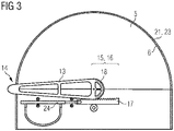
- FIG. 3 is a rear view of the in 1 shown commercial vehicle body 1.
- the swivel arm 13 Integrally with the swivel arm 13, half a gear 18 is performed. The half gear 18 meshes with the toothed rack 17 .
- the rack 17 is connected to the hydraulic cylinder 24 .
- the swivel arm 13 can be rotated in such a way that the end 14 of the swivel arm moves along the arcuate edge area 6 .
- a sliding strip 21 is located on the curved edge area 6 .
- a guide rail 23 can also be located on the curved edge area 6 .
- a cable or chain guide can also be located along the arcuate area.
- 4 1 is a perspective view of an exemplary embodiment of a truck trailer 3 according to the present invention.
- 4 shows a truck trailer 3 with a front frame module 30 and a main frame module 31.
- a coil 4 which is placed in a receiving trough 35.
- the receiving trough 35 runs from the front end 32 of the main frame module 31 to the rear end 33 of the main frame module 31.
- the receiving trough 35 runs between two longitudinal members 34, with the sloping top chords 39 of these longitudinal members 34 protruding over the luggage compartment floor 38 and representing an overhang. Viewed in the transverse direction, the receiving trough 35 has a receiving trough base 36 in the middle.
- the receiving trough can also taper to a point without a receiving trough base 36 .
- two receiving trough side walls 37 extend obliquely upwards.
- the two receiving trough side walls 37 comprise a receiving trough side wall extension 47 extending up to the upper chord 39 and the upper chord 39.
- the upper chord 39 is therefore a component of the receiving trough side wall 37.
- the upper chord 39 protrudes over the loading space floor (the tread) 38. From the front end 32 to the rear end 33 of the main frame module 31, this results in a projecting overhang of a right and a left receiving recess side wall 37.
- a luggage compartment cover (in the 4 not shown) can extend from the front end 32 to a rear end 33 of the cargo space 2 and in the transverse direction from a left-hand edge region 41 to a right-hand edge region 42 of the cargo space 2 .
- FIG 5 is a perspective view of the receiving trough 35 of FIG 4 truck trailer shown.
- the receiving trough floor 36 is recessed in relation to the loading space floor 38 .
- the upper chords 39 of the longitudinal frame members 34 form the upper region of the side walls 37 of the receiving trough.
- the receiving trough side walls 37 include a receiving trough side wall extension 47 which connects the upper chord 39 to the receiving trough base 36 .
- the receiving trough side wall 37 thus includes the upper chord 39 and the receiving trough side wall extension 37.
- the upper chords 39 protrude obliquely upwards over the loading space floor 38.
- the receiving trough side walls 37 have insertion holes 44 .
- the insertion holes 44 are formed so that stays can be inserted into them perpendicularly.
- An insert plate 48 such as a screen printing plate, is shown inserted into the receiving well side wall 37 (in Fig 4 no insert plate is shown).
- Fig. 12 is a sectional view along line AA in Fig figure 5 .
- the longitudinal frame member 34 has an upper chord 39 and a lower chord 45 .
- the upper chord 39 and the lower chord 45 are welded to the web 46 of the longitudinal frame member 34 .
- the upper chord 39 is welded at an angle to the frame longitudinal member web 34 and forms part of the (likewise at an angle) receiving trough side wall 37 .
- the receiving trough side wall 37 is thus formed in some areas by the upper chord 39 .
- the upper chord 39 protrudes obliquely upwards in the direction of the Load compartment floor 38 with the overhang Ü also.
- the upper chord 39 is canted in the downward direction.
- a receiving trough side wall extension 47 is welded to the upper chord 39 .
- the receiving trough side wall extension 47 is also canted and is connected to the receiving trough base 36 at the lower end. Due to the edging in the upper chord 39 and in the receiving trough side wall extension 47, a receiving area for an insert plate, such as a screen printing plate, is created.
- a coil 4 rests on the receiving trough side wall 37 .
- the receptacle side wall 37 and the receptacle bottom 36 are supported on the cross members 43 arranged at regular intervals from front to rear.
- the air resistance of the body during transport can be reduced in comparison to the known bodies. A saving in fuel expenses can thus be achieved.
- the curved cover continuously ensures road safety in the winter months as a result of a lack of snow and ice loads, so there is no snow load or icing on the curved loading space cover.
- the variety of components is low and the risk of permanent damage as a result of free loading space access is significantly reduced.
Abstract
Die vorliegende Erfindung betrifft einen Nutzfahrzeugaufbau (1) zum Bedecken eines Laderaums (2) eines Nutzfahrzeugs wie beispielsweise ein Lastkraftwagenanhänger (3), das zum Transportieren wenigstens eines Coils (4) ausgebildet ist, mit einer Stirnwand (5), einer Heckwand (7), einer beweglichen Abdeckung (9) und einer Verdecköffnungsvorrichtung (12). Die Stirnwand (5) weist einen bogenförmigen Randbereich (6) auf. Die Heckwand (7) ist in Längsachsenrichtung des Nutzfahrzeugaufbaus (1) in einem Abstand zu der Stirnwand (5) angeordnet und weist einen eine ähnliche Bogenform wie die Stirnwand (5) aufweisenden bogenförmigen Randbereich (8) auf. Die Verdecköffnungsvorrichtung (12) ist dazu ausgebildet, die bewegliche Abdeckung (9) von einem geschlossenen Zustand (A), bei dem der Laderaum (2) durch die bewegliche Abdeckung (9) abgedeckt ist, in einen offenen Zustand (B), bei dem das wenigstens eine Coil (4) in und aus dem Laderaum (2) bringbar ist, entlang der bogenförmigen Randbereiche (6, 8) zu verschieben. Ferner betrifft die vorliegende Erfindung ein Nutzfahrzeug (3) mit einem Laderaum (2), das zum Transportieren wenigstens eines Coils (4) ausgebildet ist, mit einer im Bereich eines Laderaumbodens (38) angeordneten Aufnahmemulde (35) mit zwei Aufnahmemuldenseitenwänden (37), wobei die Aufnahmemuldenseitenwände (37) nach oben über den Laderaumboden (38) des Laderaums (2) überstehen.The present invention relates to a commercial vehicle body (1) for covering a loading space (2) of a commercial vehicle such as a truck trailer (3), which is designed to transport at least one coil (4), with a front wall (5), a rear wall (7) , a movable cover (9) and a top opening device (12). The front wall (5) has an arcuate edge area (6). The rear wall (7) is arranged at a distance from the front wall (5) in the direction of the longitudinal axis of the commercial vehicle body (1) and has an arcuate edge region (8) having a similar arc shape to the front wall (5). The top opening device (12) is designed to move the movable cover (9) from a closed state (A), in which the loading space (2) is covered by the movable cover (9), in an open state (B) in which the at least one coil (4) can be brought into and out of the loading space (2) along the arcuate edge regions (6, 8). The present invention also relates to a commercial vehicle (3) with a loading space (2) which is designed for transporting at least one coil (4), with a receiving trough (35) arranged in the region of a loading space floor (38) and having two receiving trough side walls (37), the receiving trough side walls (37) protruding upwards over the loading space floor (38) of the loading space (2).
Description
Die vorliegende Erfindung betrifft einen Nutzfahrzeugaufbau zum Bedecken eines Laderaums eines Nutzfahrzeugs, das zum Transportieren wenigstens eines Coils ausgebildet ist. Ferner betrifft die Erfindung ein Nutzfahrzeug, das zum Transportieren wenigstens eines Coils ausgebildet ist.The present invention relates to a commercial vehicle body for covering a loading space of a commercial vehicle, which is designed to transport at least one coil. Furthermore, the invention relates to a commercial vehicle that is designed to transport at least one coil.
Im vorliegenden Fall sind unter dem Begriff Nutzfahrzeuge sowohl motorisierte Kraftfahrzeuge, die nach ihrer Bauart und Einrichtung zum Transport von Personen und Gütern oder zum Ziehen von Anhängern bestimmt sind, als auch nicht motorisierte Anhänger zu subsummieren.In the present case, the term “commercial vehicle” includes both motorized vehicles which, based on their design and equipment, are intended for transporting people and goods or for towing trailers, and non-motorized trailers.
Als Coil wird im Folgenden ein aufgewickeltes Bund von Material, wie beispielsweise Stahlrollen (Stahlcoils) oder Papierrollen (Papier-Coils) bezeichnet. Ein einzelnes Coil kann mehrere Tonnen schwer sein. Ein einzelnes Stahlcoil wiegt üblicherweise mehrere Tonnen, beispielsweise 12 Tonnen.In the following, a wound bundle of material, such as steel rolls (steel coils) or paper rolls (paper coils), is referred to as a coil. A single coil can weigh several tons. A single steel coil usually weighs several tons, for example 12 tons.
Wird für den Transport derartiger Coils ein Nutzfahrzeug wie beispielsweise ein Sattelanhänger verwendet, muss darauf geachtet werden, dass das zulässige Gesamtgewicht für Straßenfahrzeuge bzw. die zulässige Achsaggregatlast nicht überschritten werden darf sowie die erforderliche Sattellast bzw. Stützlast realisiert wird. Das Leergewicht des Nutzfahrzeugs sowie die Positionierung des Ladeguts spielt daher eine wesentliche Rolle, um das zulässige Ladegewicht für den Transport der Coils zu maximierenIf a commercial vehicle such as a semi-trailer is used to transport such coils, care must be taken to ensure that the permissible total weight for road vehicles or the permissible axle unit load is not exceeded and that the required fifth-wheel load or drawbar load is implemented. The unladen weight of the commercial vehicle and the positioning of the cargo therefore play an important role in maximizing the permissible loading weight for transporting the coils
Der für die Abdeckung des Laderaums des Nutzfahrzeugs verwendete Nutzfahrzeugaufbau besteht üblicherweise aus vier rechteckigen Seitenflächen und einer rechteckigen Dachfläche. Die Seitenflächen und die Dachfläche stehen nahezu im rechten Winkel aufeinander. In der Regel werden Planenaufbauten eingesetzt, bei denen wenigstens eine Seitenwand des Planenaufbaus durch eine faltbare Plane geöffnet und verschlossen werden kann bzw. das obere Dach geöffnet werden kann (Beladung via Schiebedach zwischen Aluminiumdachholme). Das Dach wird bei derartigen Planenaufbauten wenigstens teilweise von Rungen getragen, die sich in vertikaler Richtung vom Boden des Planenaufbaus bis zum Dach erstrecken. Dachholme und Dachquerspriegel werden dabei zur Stabilisierung sowie zur Öffnungsoption des Daches verwendet.The commercial vehicle body used to cover the loading space of the commercial vehicle usually consists of four rectangular side surfaces and a rectangular roof surface. The side surfaces and the roof surface are almost at right angles to each other. As a rule, tarpaulin bodies are used in which at least one side wall of the tarpaulin body can be opened and closed by a foldable tarpaulin or the upper roof can be opened (loading via sliding roof between aluminum roof bars). The roof will such tarpaulin structures at least partially supported by stanchions which extend in the vertical direction from the bottom of the tarpaulin structure to the roof. Roof pillars and roof crossbars are used for stabilization and for the option of opening the roof.
Bei den Nutzfahrzeugen für den Transport von Coils befindet sich üblicherweise eine Aufnahmemulde, die sogenannte Coilmulde, im Bodenbereich des Laderaums. In dieser Coilmulde kann das Coil abgelegt werden.Commercial vehicles for transporting coils usually have a receiving trough, the so-called coil trough, in the floor area of the loading space. The coil can be placed in this coil trough.
Durch das hohe Gewicht eines Coils kann es bei der Verladung des Coils in den Laderaum eines Nutzfahrzeugs, insbesondere im Bereich des Aufbaus (Kollision mit Schieberungen, Front- bzw. Heckrungen, Seitenplane bei seitlicher Beladung) bzw. Dachaufbaus (Kollision mit Aluminiumdachholmen, Dachquerspriegeln etc.) sowie des Laderaumbodens zu Beschädigungen des Nutzfahrzeugs kommen. Derartige Beschädigungen betreffen beispielsweise die Komponenten des Aufbaus sowie die Rahmenkonstruktion u.a. in Form der Längsträger eines Lastkraftwagenanhängers.Due to the high weight of a coil, when loading the coil into the loading space of a commercial vehicle, particularly in the area of the body (collision with sliding stanchions, front or rear stanchions, side tarpaulins when loading from the side) or the roof structure (collision with aluminum roof bars, roof crossbars, etc.) .) and the load compartment floor can damage the commercial vehicle. Such damage affects, for example, the components of the body and the frame construction, e.g. in the form of the side members of a truck trailer.
Das der Erfindung zugrunde liegende technische Problem besteht darin, bekannte Nutzfahrzeuge für den Coil-Transport, insbesondere hinsichtlich des Gewichts, der barrierefreien Beladung sowie der Verkehrssicherheit, zu verbessern.The technical problem on which the invention is based consists in improving known commercial vehicles for coil transport, in particular with regard to weight, barrier-free loading and traffic safety.
Gemäß einem ersten Aspekt der vorliegenden Erfindung wird das der Erfindung zugrunde liegende technische Problem durch einen Nutzfahrzeugaufbau zum Bedecken eines Laderaums eines Nutzfahrzeugs wie beispielsweise ein Lastkraftwagenanhänger, das zum Transportieren wenigstens eines Coils ausgebildet ist, gelöst. Der Nutzfahrzeugaufbau umfasst eine Stirnwand, die einen bogenförmigen Randbereich aufweist, und eine Heckwand, die in Längsachsenrichtung des Nutzfahrzeugaufbaus in einem Abstand zu der Stirnwand angeordnet ist und einen eine ähnliche Bogenform wie die Stirnwand aufweisenden bogenförmigen Randbereich aufweist. Ferner umfasst der Nutzfahrzeugaufbau eine bewegliche Abdeckung, die sich von der Stirnwand bis zu der Heckwand erstreckt und entlang der bogenförmigen Randbereiche führbar ist, und eine Verdecköffnungsvorrichtung, die dazu ausgebildet ist, die bewegliche Abdeckung von einem geschlossenen Zustand, bei dem der Laderaum durch die bewegliche Abdeckung abgedeckt ist, in einen offenen Zustand, bei dem das wenigstens eine Coil in und aus dem Laderaum bringbar ist, entlang der bogenförmigen Randbereiche zu bewegen.According to a first aspect of the present invention, the technical problem on which the invention is based is solved by a commercial vehicle body for covering a loading space of a commercial vehicle such as a truck trailer, which is designed to transport at least one coil. The utility vehicle body includes a bulkhead having an arcuate edge portion, and a rear wall spaced apart from the bulkhead in the longitudinal axis direction of the utility vehicle body and having an arcuate edge portion having an arcuate shape similar to that of the bulkhead. Furthermore, the commercial vehicle body comprises a movable cover, which extends from the front wall to the rear wall and can be guided along the arcuate edge areas, and a convertible top opening device, which is designed to open the movable cover from a closed state in which the loading space is opened by the movable cover is covered, in an open state, in which the at least one coil can be brought in and out of the hold to move along the arcuate edge regions.
Mit dem erfindungsgemäßen Nutzfahrzeugaufbau ist es möglich, das Gewicht im Vergleich zu bekannten Nutzfahrzeugaufbauten, die bei dem Transport von Coils eingesetzt werden, infolge der technischen Ausgestaltung erheblich zu reduzieren. Mit dem erfindungsgemäßen Nutzfahrzeugaufbau lassen sich Leergewichte von Lastkraftwagenanhängern für den Coil-Transport von unter 4 Tonnen realisieren.With the commercial vehicle body according to the invention, it is possible to reduce the weight considerably compared to known commercial vehicle bodies that are used to transport coils as a result of the technical design. With the commercial vehicle body according to the invention, empty weights of truck trailers for coil transport of less than 4 tons can be achieved.
Die bogenförmige Laderaumabdeckung kann beispielsweise kreisbogenförmig oder als Teil einer ovalen Form ausgebildet sein.The arcuate luggage compartment cover can be designed, for example, in the shape of a circular arc or as part of an oval shape.
Der bogenförmige Randbereich der Heckwand kann die gleiche Bogenform wie der Randbereich der die Stirnwand aufweisen oder eine andere Bogenform aufweisen.The arcuate edge area of the rear wall can have the same arc shape as the edge area of the front wall or can have a different arc shape.
Die bewegliche Abdeckung ist bevorzugt als faltbare Plane, faltbare Folie oder durch faltbare Kunststoffelemente oder Metallelemente ausgebildet. Die bewegliche Abdeckung kann weiterhin als Rollplane bzw. bewegliche Aluminiumlamelle ausgebildet sein.The movable cover is preferably designed as a foldable tarpaulin, foldable foil or by foldable plastic elements or metal elements. The movable cover can also be designed as a roll-up tarpaulin or movable aluminum slat.
Weiterhin wird durch die bogenförmige Abdeckung die Verkehrssicherheit in den Wintermonaten infolge einer ausbleibenden Schnee- und Eislast durchgängig gewährleistet. Aufgrund der Bogenform der beweglichen Abdeckung existiert keine oder nur geringe Schneelast bzw. Vereisung auf der Laderaumabdeckung. Auf den Einsatz eines Anti-Ice-Systems bzw. einer Enteisungsleiter und dergleichen kann verzichtet werden.Furthermore, the arched cover ensures traffic safety throughout the winter months due to the lack of snow and ice loads. Due to the curved shape of the movable cover, there is little or no snow load or icing on the luggage compartment cover. The use of an anti-ice system or a de-icing ladder and the like can be dispensed with.
Gleichzeitig weist der erfindungsgemäße Nutzfahrzeugaufbau eine massive Bauweise mit hoher Betriebsfestigkeit auf. Dies wird dadurch erreicht, dass der erfindungsgemäße Nutzfahrzeugaufbau im Vergleich zu bekannten Nutzfahrzeugaufbauten weniger aufwändig und bauteilintensiv ausgebildet ist. So kann bei dem erfindungsgemäßen Nutzfahrzeugaufbau beispielsweise auf eine Vielzahl von Rungen, auf Dachquerspriegel, auf Aluminium-Dachholme, Einstecklatten, Ladungssicherungsbalken, auf Front- bzw. Hecktüren oder auf Stahl-Schieberungen verzichtet werden.At the same time, the commercial vehicle body according to the invention has a solid construction with high operational strength. This is achieved in that the commercial vehicle body according to the invention is designed to be less complex and component-intensive than known commercial vehicle bodies. In the commercial vehicle body according to the invention, for example, a large number of stanchions, cross-roof bows, aluminum roof rails, slats, load-securing beams, front and rear doors or steel slides can be dispensed with.
Mithilfe der Verdecköffnungsvorrichtung kann die bewegliche Abdeckung zwischen einem geschlossenen Zustand und einem offenen Zustand hin- und herverschoben werden. Im offenen Zustand ist die bewegliche Abdeckung so positioniert, dass das Coil in den Laderaum einbringbar ist. Bevorzugt ist der Nutzfahrzeugaufbau so ausgebildet, dass eine Coil-Fahrzeugbeladung via Kran von oben erfolgen kann.With the help of the top opening device, the movable cover can be shifted back and forth between a closed state and an open state. When open, the movable cover is positioned in such a way that the coil can be brought into the loading space. The commercial vehicle structure is preferred designed in such a way that a coil vehicle can be loaded from above using a crane.
Zum Betreiben der Verdecköffnungsvorrichtung, d.h. zum Verschieben der beweglichen Abdeckung, können elektrische, pneumatische, hydraulische oder rein mechanische Antriebe eingesetzt werden.Electric, pneumatic, hydraulic or purely mechanical drives can be used to operate the convertible top opening device, i.e. to move the movable cover.
Im offenen Zustand wird das Einbringen von Coils in den Laderaum nicht durch Aluminium Dachholme, Dachquerspriegel, Schieberungen oder ein Planenoberdach erschwert. Der Laderaum ist hingegen seitlich sowie nach oben absolut offen. Dadurch kann es nicht zu einer Beschädigung von Komponenten wie einem Dachholm bzw. Führungsschienen der Seitenplanen, Free-Load-System bzw. der zusammengeschobenen (komprimierten) Dachquerspriegel nebst Dachplane etc. kommen.When open, the introduction of coils into the cargo area is not made more difficult by aluminum roof bars, roof crossbars, sliding stanchions or a tarpaulin roof. The cargo area, on the other hand, is completely open at the sides and at the top. This prevents damage to components such as a roof rail or guide rails of the side tarpaulins, free-load system or the pushed together (compressed) roof crossbars together with the roof tarpaulin, etc.
Ferner kann mit dem erfindungsgemäßen Nutzfahrzeugaufbau der Luftwiderstand des Aufbaus beim Transport im Vergleich zu den bekannten Aufbauten erheblich reduziert werden. Durch die bogenförmige Rahmenfront nebst bogenförmigen, beispielsweise runden oder ovalem Fahrzeugaufbau kann die Aerodynamik deutlich verbessert werden und somit eine Einsparung von Kraftstoffaufwendungen erreicht werden.Furthermore, with the commercial vehicle body according to the invention, the air resistance of the body during transport can be significantly reduced compared to the known bodies. The aerodynamics can be significantly improved by the arcuate frame front together with the arcuate, for example round or oval vehicle structure, and thus savings in fuel costs can be achieved.
Gemäß einer bevorzugten Ausführungsform weist der Nutzfahrzeugaufbau wenigstens eine Verstrebung auf. Die Verstrebung ist in einem Abstand zwischen der Stirnwand und der Heckwand angeordnet und weist einen bogenförmigen Randbereich, der eine ähnliche Bogenform wie die Stirn- und die Heckwand aufweist und entlang dem die bewegliche Abdeckung zusätzlich abgestützt ist, auf.According to a preferred embodiment, the utility vehicle body has at least one strut. The brace is spaced between the bulkhead and the rear wall and has an arcuate edge portion which has a similar arcuate shape to the bulkhead and the rear wall and along which the movable cover is additionally supported.
Die wenigstens eine Verstrebung sorgt für eine zusätzliche Führung der beweglichen Abdeckung. Somit kann beispielsweise ein Durchhängen der beweglichen Abdeckung zwischen der Stirnwand und der Heckwand reduziert werden. Ein kontrolliertes Verschieben der beweglichen Abdeckung zwischen dem geschlossenen Zustand und dem offenen Zustand wird verbessert. Mehrere Verstrebungen sind vorzugsweise gleichmäßig in Längsachsenrichtung zwischen der Stirnwand und der Heckwand ausgerichtet. Bevorzugt weisen die bogenförmigen Randbereiche der Verstrebung, der Stirnwand und der Heckwand die gleiche Bogenform auf.The at least one strut provides additional guidance for the movable cover. Thus, for example, sagging of the movable cover between the bulkhead and the rear wall can be reduced. Controlled sliding of the movable cover between the closed condition and the open condition is improved. A plurality of struts are preferably evenly aligned in the longitudinal axis direction between the bulkhead and the rear bulkhead. The curved edge areas of the strut, the front wall and the rear wall preferably have the same curved shape.
Die wenigstens eine Verstrebung kann beispielsweise als Steckverbindung von Aluminium-, Stahl-, Kunststoff-, Glasfaser- oder Holz-Streben ausgebildet sein.The at least one strut can be designed, for example, as a plug-in connection of aluminum, steel, plastic, glass fiber or wooden struts.
Gemäß einer bevorzugten Ausführungsform weist die wenigstens eine Verstrebung eine sich derart in den Laderaum erstreckende Strebe auf, dass diese innerhalb des Laderaums eine Anlage für das wenigstens eine Coil schafft.According to a preferred embodiment, the at least one strut has a strut that extends into the loading space in such a way that it creates a support for the at least one coil within the loading space.
Die sich in den Laderaum erstreckende Strebe der wenigstens einen Verstrebung schafft eine Anlagefläche für ein Coil. Die Strebe ist so ausgebildet, dass sie fest mit dem Boden des Laderaums verbindbar ist. Auf diese Weise ist es möglich, die Anlagefläche als zusätzliche Verschiebesicherung für ein Coil innerhalb des Laderaums zu benutzen. Es kann dadurch eine formschlüssige Ladungssicherung erreicht werden. Beispielsweise kann das Coil mit Zurrgurten gegen die Strebe verzurrt werden. Das Coil ist somit gegen Längsbewegung in dem Laderaum gesichert.The strut of the at least one strut, which extends into the loading space, creates a contact surface for a coil. The strut is designed in such a way that it can be firmly connected to the floor of the loading space. In this way it is possible to use the contact surface as an additional anti-displacement device for a coil within the hold. In this way, a form-fit load securing can be achieved. For example, the coil can be lashed against the strut with lashing straps. The coil is thus secured against longitudinal movement in the hold.
Beispielsweise kann die Anlagefläche die Seitenfläche von Stahlsteckrungen sein, die in Aufnahmen in dem Boden des Laderaums einsteckbar sind. Bevorzugt sind der bogenförmige Randbereich der Verstrebung und die sich in den Laderaum erstreckende Strebe miteinander verbunden.For example, the contact surface can be the side surface of steel plug-in stanchions that can be inserted into receptacles in the floor of the hold. The arcuate edge region of the strut and the strut extending into the loading space are preferably connected to one another.
Gemäß einer bevorzugten Ausführungsform weist die Verdecköffnungsvorrichtung einen Schwenkarm und einen Antrieb auf. Der Schwenkarm ist an einem Schwenkarmende mit der beweglichen Abdeckung verbindbar und an einem Schwenkarmkopfbereich drehbar gelagert. Der Antrieb ist mit dem Schwenkarmkopfbereich verbunden und dazu ausgebildet, den Schwenkarm zu drehen und durch die Drehung die bewegliche Abdeckung zwischen dem geschlossenen Zustand und dem offenen Zustand hin und her zu bewegen. Die Verdecköffnungsvorrichtung weist einen Schwenkarm und einen Antrieb im Bereich der Stirnwand und/oder im Bereich der Heckwand auf. Das Schwenkarmende bewegt sich bei Drehung des Schwenkarms entlang des bogenförmigen Randbereichs.According to a preferred embodiment, the convertible top opening device has a swivel arm and a drive. The swivel arm can be connected to the movable cover at a swivel arm end and is rotatably mounted on a swivel arm head area. The driver is coupled to the swing arm head portion and is configured to rotate the swing arm and, through the rotation, move the movable cover back and forth between the closed condition and the open condition. The convertible top opening device has a swivel arm and a drive in the area of the bulkhead and/or in the area of the rear wall. The swivel arm end moves along the arcuate edge area when the swivel arm rotates.
Ein Schwenkarm ist eine einfache und zuverlässige Methode die bewegliche Abdeckung des Laderaums zwischen dem geschlossenen Zustand und dem offenen Zustand zu bewegen. Der Schwenkarm muss dazu nur um eine Achse gedreht werden. Es sind keine translatorischen Bewegungen des Schwenkarms notwendig. Die Verdecköffnungsvorrichtung kann einen Schwenkarm im Bereich der Stirnwand und/oder Heckwand aufweisen oder jeweils einen Schwenkarm im Bereich der Stirnwand und/oder der Heckwand. Der Schwenkarm ist so gelagert, dass sich das Schwenkarmende entlang des bogenförmigen Randbereichs der Stirnwand beziehungsweise der Heckwand bewegt. Im Bereich der drehbaren Lagerung des Schwenkarms ist der Schwenkarm mit einem Antrieb verbunden, mit dem der Schwenkarm gedreht werden kann. Bei der Verwendung von zwei Schwenkarmen können die Antriebe, die mit den Schwenkarmen verbunden sind, so ausgelegt sein, dass sie synchron zueinander laufen können und die bewegliche Abdeckung somit kontrolliert verschieben.A swing arm is a simple and reliable method of moving the movable cargo area cover between the closed position and the open position. The swivel arm only has to be rotated around one axis. No translational movements of the swivel arm are necessary. The convertible top opening device can have a swivel arm in the area of the front wall and/or the rear wall or a swivel arm in the area of the front wall and/or the rear wall. The swivel arm is mounted in such a way that the end of the swivel arm moves along the arcuate edge area of the front wall or the rear wall. In the area of the rotatable mounting of the swivel arm, the swivel arm is connected to a drive with which the Swivel arm can be rotated. When using two swivel arms, the drives that are connected to the swivel arms can be designed in such a way that they can run synchronously with one another and thus move the movable cover in a controlled manner.
Gemäß einer bevorzugten Ausführungsform ist der Antrieb der Verdecköffnungsvorrichtung ein Zahnstangenantrieb, der durch lineares Verschieben einer Zahnstange über ein mit dem Schwenkarm verbundenes Zahnrad die Drehung des Schwenkarms erzeugt oder bei dem der Antrieb ein Schnecken- oder Kegelradgetriebe aufweist.According to a preferred embodiment, the drive of the top opening device is a rack and pinion drive, which generates the rotation of the swivel arm by linear displacement of a toothed rack via a gear wheel connected to the swivel arm, or in which the drive has a worm or bevel gear.
Als einfacher und zuverlässiger Antrieb kann ein Zahnstangenantrieb verwendet werden. Die lineare Verschiebung der Zahnstange des Zahnstangenantriebs kann beispielsweise mit einem Zylinder (hydraulisch, pneumatisch, elektrisch etc.), einer Hand-Hydraulikpumpe, einer Elektrohydraulikpumpe, einer Pneumatikpumpe, einem Pneumatikkompressor oder einem manuellen Getriebe realisiert werden. Alternativ kann anstelle des Zahnstangenantriebs beispielsweise auch ein Antrieb verwendet werden, der ein Schnecken- oder Kegelradgetriebe zur Bewegungsausführung des Schwenkarms aufweist.A rack and pinion drive can be used as a simple and reliable drive. The linear displacement of the rack of the rack and pinion drive can be implemented, for example, with a cylinder (hydraulic, pneumatic, electric, etc.), a manual hydraulic pump, an electrohydraulic pump, a pneumatic pump, a pneumatic compressor or a manual gear. Alternatively, instead of the rack and pinion drive, a drive can also be used, for example, which has a worm gear or bevel gear for moving the swivel arm.
Das Zahnrad des Zahnstangenantriebs kann beispielsweise in Form eines integral mit dem Schwenkarm verbundenen halben Zahnrads ausgebildet sein.The toothed wheel of the rack and pinion drive can be designed, for example, in the form of a half toothed wheel which is integrally connected to the swivel arm.
Gemäß einer bevorzugten Ausführungsform weist die bewegliche Abdeckung einen versteiften Randbereich, der mit der Verdecköffnungsvorrichtung verbunden ist, auf. Ferner weist die Stirnwand und die Heckwand entlang der bogenförmigen Randbereiche einen Gleitstreifen, der dazu ausgebildet ist, dass der versteifte Randbereich der beweglichen Abdeckung darauf gleitbar ist und/oder eine Führungsschiene, die dazu ausgebildet ist, dass der versteifte Randbereich beweglichen Abdeckung darauf führbar ist und/oder eine Seil- oder Kettenführung, die dazu ausgebildet ist, die bewegliche Abdeckung entlang der bogenförmigen Randbereiche zu führen, auf.According to a preferred embodiment, the movable cover has a stiffened edge area which is connected to the top opening device. Furthermore, the front wall and the rear wall have along the arcuate edge areas a sliding strip which is designed to allow the stiffened edge area of the movable cover to slide thereon and/or a guide rail which is designed to allow the stiffened edge area of the movable cover to be guided thereon and /or a cable or chain guide designed to guide the movable cover along the arcuate edge areas.
Für eine gute Krafteinleitung/Kraftverteilung in die bewegliche Abdeckung bei dem Verschieben der beweglichen Abdeckung durch die Verdecköffnungsvorrichtung kann die bewegliche Abdeckung im Randbereich versteift ausgeführt sein. Eine derartige Versteifung kann beispielsweise mithilfe eines steifen Materials im Randbereich oder durch Verwendung von Seilen, Ketten etc. geschaffen werden. Alternativ kann die bewegliche Abdeckung mit einem Versteifungsglied versehen sein. Beispielsweise kann dies eine Metallstange sein, die von der Stirnwand bis zu der Heckwand mit der beweglichen Abdeckung im Randbereich der beweglichen Abdeckung verbunden ist. Die Verdecköffnungsvorrichtung leitet die Kraft in diesem Bereich in die bewegliche Abdeckung ein. Im Falle einer ausreichenden Steifigkeit der beweglichen Abdeckung kann auch auf eine Versteifung des Randbereichs verzichtet werden.For good force introduction/force distribution in the movable cover when the movable cover is displaced by the convertible top opening device, the movable cover can be stiffened in the edge area. Such a stiffening can be created, for example, using a stiff material in the edge area or by using ropes, chains, etc. Alternatively, the movable cover with a stiffening member be provided. For example, this can be a metal bar that is connected to the movable cover from the front wall to the rear wall in the edge area of the movable cover. The convertible top opening device transfers the force in this area to the movable cover. If the movable cover is sufficiently rigid, it is also possible to dispense with stiffening the edge area.
Für eine kontrollierte Führung und/oder ein reibungsarmes Verschieben der beweglichen Abdeckung bzw. des versteiften Randbereichs können die bogenförmigen Randbereiche der Stirnwand und Heckwand mit Gleitstreifen und/oder Führungsschienen und/oder Seilen und/oder Ketten versehen sein.For controlled guidance and/or low-friction displacement of the movable cover or the stiffened edge area, the curved edge areas of the front wall and rear wall can be provided with sliding strips and/or guide rails and/or cables and/or chains.
Beispielsweise werden Führungsschienen auf dem bogenförmigen Randbereich der Stirnwand und Heckwand befestigt. Die bewegliche Abdeckung ist im versteiften Randbereich mit entsprechenden, in die Führungsschiene eingreifenden Verbindungsgliedern oder Rollen versehen.For example, guide rails are fastened to the curved edge area of the bulkhead and rear wall. In the stiffened edge area, the movable cover is provided with corresponding connecting members or rollers which engage in the guide rail.
Alternativ kann auch eine Verdecköffnungsvorrichtung verwendet werden, bei der die bewegliche Abdeckung mit einer Seil- oder Kettenführung entlang der bogenförmigen Randbereiche geführt wird. Beispielsweise kann eine Seilführung verwendet werden, wie sie derzeit bei den Schiebeverdecken, Model Galoppino von Cramaro zum Einsatz kommen.Alternatively, a convertible top opening device can also be used, in which the movable cover is guided along the curved edge regions with a cable or chain guide. For example, a cable guide can be used, as is currently used in the sliding roofs, model Galoppino from Cramaro.
Im Stirnbereich und Heckbereich des Nutzfahrzeugaufbaus kann die bewegliche Abdeckung beispielsweise via Überlappung nebst Expanderseil sowie infolge von mehrfach in Abständen in der beweglichen Abdeckung integrierten Aluminiumstangen gesichert werden.In the front and rear area of the commercial vehicle body, the movable cover can be secured, for example, via an overlap with an expander cable and as a result of aluminum bars integrated into the movable cover several times at intervals.
Gemäß einer bevorzugten Ausführungsform weist die wenigstens eine Verstrebung entlang des bogenförmigen Randbereichs einen Gleitstreifen und/oder eine Führungsschiene und/oder eine Seil-/Kettenführung auf.According to a preferred embodiment, the at least one strut has a sliding strip and/or a guide rail and/or a cable/chain guide along the curved edge area.
Wie auf den bogenförmigen Randbereichen der Stirnwand und Heckwand können sich ein Gleitstreifen und/oder Führungsschienen auch in dem bogenförmigen Randbereich der einen oder mehreren Verstrebungen befinden. Dadurch wird die reibungsarme und/oder kontrollierte Führung der beweglichen Abdeckung weiter verbessert.As on the arcuate edge portions of the bulkhead and rear wall, a slide strip and/or guide rails may also be located in the arcuate edge portion of the one or more struts. This further improves the low-friction and/or controlled guidance of the movable cover.
Gemäß einem weiteren Aspekt der vorliegenden Erfindung wird das der Erfindung zugrunde liegende technische Problem durch ein Nutzfahrzeug mit einem Laderaum, das zum Transportieren wenigstens eines Coils ausgebildet ist, mit einer im Bereich eines Laderaumbodens angeordneten Aufnahmemulde mit zwei Aufnahmemuldenseitenwänden gelöst. Die zwei Aufnahmemuldenseitenwände erstrecken sich schräg nach oben, in entgegengesetzter horizontaler Richtung. Die Aufnahmemuldenseitenwände stehen nach oben über den Laderaumboden des Laderaums mit einem Überstand über.According to a further aspect of the present invention, the technical problem on which the invention is based is also solved by a commercial vehicle with a loading space which is designed to transport at least one coil a receiving trough with two receiving trough side walls arranged in the area of a luggage compartment floor. The two receptacle side walls extend obliquely upwards in opposite horizontal directions. The receiving trough side walls protrude upwards over the load compartment floor of the load compartment with an overhang.
Mit dem erfindungsgemäßen Nutzfahrzeug wird eine Führung nebst optimierter Aufnahme des Coils bzw. unterschiedlicher Coilgrößen sowie eine verbesserte Krafteinleitung in die gesamte Fahrzeugkonstruktion durch die hervorstehenden Aufnahmemuldenseitenwände bei Einlegen des Coils in die Aufnahmemulde ermöglicht. Die Aufnahmemuldenseitenwände stehen über den Laderaumboden über. Somit wird das Coil während des Beladevorganges durch die beidseitig auskragenden bzw. überstehenden Aufnahmemuldenseitenwände geführt und kann dadurch exakt in der Aufnahmemulde positioniert werden. Infolgedessen wird eine "tiefere" Aufnahmemulde zur verbesserten Aufnahme sowie Ladungssicherung eines tonnenschweren Coils geschaffen.With the commercial vehicle according to the invention, guidance is made possible along with optimized accommodation of the coil or different coil sizes and an improved introduction of force into the entire vehicle structure through the protruding reception trough side walls when the coil is inserted into the reception trough. The receiving trough side walls protrude over the load compartment floor. The coil is thus guided during the loading process by the side walls of the receiving trough that cantilever or protrude on both sides and can therefore be positioned exactly in the receiving trough. As a result, a "deeper" receiving trough is created for improved receiving and load securing of a coil weighing several tons.
Ferner kann eine Beschädigung des Nutzfahrzeugs, der Trittflächen, der Aufnahmemulde sowie des Fahrzeugrahmens durch die hervorstehenden Aufnahmemuldenseitenwände reduziert werden. Gleichsam wie ein "Puffer" können die hervorstehenden Aufnahmemuldenseitenwände Verformungsenergie aufnehmen und somit den Boden des Laderaums und die darunter befindlichen Bauteile des Nutzfahrzeugs vor Beschädigung durch das Coil z. B. plastische Deformation durch ein zügiges Ablegen des Coils im Rahmen eines Beladungsvorgangs infolge übermäßiger Krafteinleitung / Krafteinwirkung in die Bauteile des Nutzfahrzeuges bzw. in die Fahrzeugrahmenkonstruktion resultierend aus einer stoßartigen Punktbelastung schützen. Beispielsweise kann es durch ein zu schnell herabgelassenes oder herabfallendes Coil zu einer derartigen Beschädigung kommen.Furthermore, damage to the commercial vehicle, the treads, the receiving trough and the vehicle frame can be reduced by the protruding receiving trough side walls. Like a "buffer", the protruding receiving trough side walls can absorb deformation energy and thus protect the floor of the loading space and the components of the commercial vehicle underneath from damage by the coil, e.g. B. protect against plastic deformation by swiftly depositing the coil during a loading process as a result of excessive force application / force in the components of the commercial vehicle or in the vehicle frame structure resulting from a sudden point load. For example, such damage can result from a coil being lowered or falling down too quickly.
Die Aufnahmemulde ist so ausgebildet, dass sie derart abdeckbar ist, dass zwischen den überkragenden Enden der Aufnahmemuldenseitenwände eine ebene Auflagefläche entsteht. Auf diese Weise können auch anderweitige Ladegüter als ein Coil transportiert werden. Der sich neben der Aufnahmemulde erstreckende Laderaumboden kann ebenfalls abgedeckt werden, um den Höhenunterschied des Überstands der Aufnahmemuldenseitenwand auszugleichen und über den gesamten Laderaum hinweg eine ebene Bodenfläche zu erhalten.The receiving trough is designed in such a way that it can be covered in such a way that a flat support surface is created between the overhanging ends of the receiving trough side walls. In this way, loads other than a coil can also be transported. The luggage compartment floor extending next to the receiving trough can also be covered in order to compensate for the difference in height of the overhang of the receiving trough side wall and to obtain a level floor surface over the entire luggage compartment.
Gemäß einer bevorzugten Ausführungsform ist die Aufnahmemuldenseitenwand, zumindest bereichsweise, durch einen Obergurt eines Rahmenlängsträgers des Nutzfahrzeugs ausgebildet.According to a preferred embodiment, the receiving trough side wall is formed, at least in regions, by an upper chord of a longitudinal frame member of the utility vehicle.
Bevorzugt sind die Obergurte der Rahmenlängsträger mit dem Steg des Rahmenlängsträgers integral ausgebildet, insbesondere verschweißt. Der Obergurt ist dabei schräg gestellt, bzw. gekippt. Bevorzugt bilden die Obergurte den auskragenden Überstand der Aufnahmemuldenseitenwände über den Laderaumboden aus. Infolge dieses Überstands entsteht eine Coilauflage auf dem Rahmenhauptlängsträger. Die Last bzw. die Masse/Gewichtskraft wird direkt in die Rahmenkonstruktion eingeleitet und der zu transportierende Coil stützt sich bevorzugt über den Obergurt auf dem Fahrzeugrahmen ab. Alternativ kann der Obergurt auch lösbar mit dem Steg des Rahmenlängsträgers, beispielsweise in Form einer Steckverbindung, verbunden sein.Preferably, the upper flanges of the longitudinal frame members are formed integrally with the web of the longitudinal frame member, in particular welded. The upper chord is placed at an angle or tilted. The top chords preferably form the cantilevered overhang of the receiving trough side walls over the loading space floor. As a result of this overhang, there is a coil rest on the main longitudinal member of the frame. The load or the mass/weight force is introduced directly into the frame construction and the coil to be transported is preferably supported on the vehicle frame via the upper flange. Alternatively, the top chord can also be releasably connected to the web of the longitudinal frame member, for example in the form of a plug-in connection.
Durch die zumindest teilweise Ausgestaltung der Aufnahmemuldenseitenwand durch den Obergurt wird eine direkte Einleitung der Masse/Gewichtskraft in die Rahmenkonstruktion erreicht. Damit unterscheidet sich diese Ausführungsform von bekannten Coil-Aufliegern, bei denen die Last bzw. Kraft in eine Coilmulde, die nicht der Obergurt ist und welche seitlich in bzw. zwischen die Hauptträger eingespannt ist, eingeleitet wird.Due to the at least partial configuration of the side wall of the receiving trough by the upper chord, a direct introduction of the mass/weight force into the frame construction is achieved. In this way, this embodiment differs from known coil semi-trailers in which the load or force is introduced into a coil trough which is not the top chord and which is clamped laterally in or between the main beams.
Durch die erfindungsgemäße zumindest bereichsweise integrale Ausbildung von Aufnahmemuldenseitenwand und Obergurt des Rahmenlängsträgers ergibt sich ein optimierter Kraftfluss und eine enorme Betriebsfestigkeit.The at least regionally integral design of the receiving trough side wall and upper flange of the frame side member according to the invention results in an optimized flow of forces and enormous operational strength.
Beispielsweise stehen die Obergurte der Rahmenlängsträger ca. 50 mm über die seitlichen Trittflächen, i.e. der Laderaumboden, hinaus. Durch Verbreiterung der betreffenden Obergurte ist es möglich, die Aufnahmemuldenseitenwände ausgeprägter über den Laderaumboden / Trittbereich hinausragen zu lassen. Dadurch kann ein Coil mit größerem Durchmesser optimiert geladen und dabei geführt werden. Der auskragende Überstand ist vergrößert und der Coil mit größerem Durchmesser (z.B. Papiercoil) liegt auf diesen Obergurten auf. Die Gewichtskraft wird direkt in den Fahrzeugrahmen, insbesondere die Rahmenhauptlängsträger, eingeleitet. Mithin liegt der Coil nicht auf dem Aufnahmemuldenboden auf, sondern auf den Aufnahmemuldenseitenwänden (insbesondere dem Obergurt). Die Kräfte werden somit in den Fahrzeugrahmen und gerade nicht ausschließlich in den Coilmuldenboden eingeleitet.For example, the upper chords of the longitudinal frame members protrude approx. 50 mm over the side steps, ie the load compartment floor. By widening the relevant top chords, it is possible to have the side walls of the receiving trough protrude more clearly over the floor of the luggage compartment / step area. This allows a coil with a larger diameter to be loaded and guided in an optimized manner. The protruding overhang is increased and the coil with a larger diameter (e.g. paper coil) rests on these top chords. The weight force is introduced directly into the vehicle frame, in particular the main frame longitudinal members. Consequently, the coil does not rest on the bottom of the receiving trough, but on the side walls of the receiving trough (in particular the top flange). The forces are thus introduced into the vehicle frame and not exclusively into the coil trough floor.
Bevorzugt ist der Obergurt mit dem Steg des Rahmenlängsträgers verschweißt. Eine derartige einteilige Ausführung der Längsträger mit der Aufnahmemuldenseitenwand stellt infolge der schweißtechnisch durchgängig verbundenen Bauteile eine hinsichtlich der Betriebsfestigkeit erheblich optimierte Ausgestaltung dar. Daraus resultierend können die Materialstärken bzw. Materialquerschnitte umfangreich reduziert werden. Als Folge kann eine Gewichtsersparnis, eine Erhöhung des Ladungsgewichtes ohne Überschreitung des zulässigen Gesamtgewichtes und eine Kraftstoffeinsparung erzielt werden.The upper chord is preferably welded to the web of the longitudinal frame member. Such a one-piece design of the longitudinal members with the side wall of the receiving trough represents a design that is significantly optimized in terms of operational stability due to the components that are continuously welded by welding. As a result, the material thicknesses and material cross sections can be extensively reduced. As a result, weight saving, an increase in cargo weight without exceeding the gross vehicle weight rating, and fuel economy can be achieved.
Bevorzugt wird an den Obergurt nach unten eine Aufnahmemuldenseitenwandverlängerung angebracht. Die Aufnahmemuldenseitenwandverlängerung kann beispielsweise an den Obergurt angeschweißt sein. Alternativ kann sie auch mit einer lösbaren Verbindung mit dem Obergurt verbunden sein. Der Obergurt sowie die Verlängerung sind bevorzugt gekantet. Dadurch entsteht ein Aufnahmebereich für beispielsweise Siebdruckplatten, welche in die Aufnahmemuldenseitenwand einlegbar sind. Entsprechend umfasst die Aufnahmemuldenseitenwand den Obergurt im oberen Bereich und eine Aufnahmemuldenseitenwandverlängerung im unteren Bereich. An den Obergurt kann schräg nach oben eine weitere Aufnahmemuldenseitenwandverlängerung angebracht, beispielsweise angeschweißt, sein, durch die die Aufnahmemuldenseitenwand nach oben verlängert wird.A receiving trough side wall extension is preferably attached to the top chord downwards. The receiving trough side wall extension can be welded to the upper chord, for example. Alternatively, it can also be connected to the upper chord with a detachable connection. The top chord and the extension are preferably canted. This creates a receiving area for screen printing plates, for example, which can be inserted into the side wall of the receiving cavity. Correspondingly, the receiving trough side wall comprises the upper chord in the upper area and an accommodating trough side wall extension in the lower area. A further trough side wall extension can be attached, for example welded, to the upper chord at an angle upwards, through which the trough side wall is extended upwards.
Bevorzugt erstreckt sich die Aufnahmemulde in Längsrichtung des Nutzfahrzeugs, d.h. von einem vorderen Bereich des Nutzfahrzeugs zu einem hinteren Bereich des Nutzfahrzeugs. Die Aufnahmemuldenseitenwände können dann als eine linke und eine rechte Aufnahmemuldenseitenwand bezeichnet werden. Die linke Aufnahmemuldenseitenwand erstreckt sich in Querrichtung schräg nach links-oben und die rechte Aufnahmemuldenseitenwand erstreckt sich in Querrichtung schräg nach rechts-oben.The receiving trough preferably extends in the longitudinal direction of the utility vehicle, i.e. from a front area of the utility vehicle to a rear area of the utility vehicle. The well sidewalls can then be referred to as left and right well sidewalls. The left receiver well side wall extends laterally obliquely left-upper, and the right receiver well side wall extends laterally obliquely right-upper.
Bevorzugt erstecken sich die linke und rechte Aufnahmemuldenseitenwand von dem Vorderende bis zu einem Hinterende des Laderaums. Die Aufnahmemulde kann sich aber auch nur über einen Teilbereich zwischen dem Vorderende und einem Hinterende des Laderaums erstrecken.Preferably, the left and right receptacle sidewalls extend from the front end to a rear end of the cargo space. However, the receiving trough can also only extend over a partial area between the front end and a rear end of the loading space.
Bevorzugt ist die Aufnahmemulde mit einem Aufnahmemuldenboden, der zwischen den beiden Aufnahmemuldenseitenwänden liegt, ausgeführt. Alternativ kann die Aufnahmemulde ohne Boden ausgebildet sein oder können die zwei Aufnahmemuldenseitenwände auch direkt miteinander verbunden sein. Entsprechend kann die Aufnahmemulde eine spitze bzw. dreieckförmige Ausgestaltung aufweisen. Bevorzugt ist der Aufnahmemuldenboden mit der Aufnahmemuldenseitenwand verschweißt oder einstückig ausgeführt. Der Aufnahmemuldenboden kann aber auch lösbar mit der Aufnahmemuldenseitenwand, beispielsweise mit einer Steckverbindung, verbunden sein.The receiving trough is preferably designed with a receiving trough base which lies between the two receiving trough side walls. Alternatively, the receiving trough can be designed without a base or the two receiving trough side walls can also be connected directly to one another. Corresponding the receiving trough can have a pointed or triangular configuration. The receiving trough base is preferably welded to the receiving trough side wall or is designed in one piece. However, the receiving trough base can also be releasably connected to the receiving trough side wall, for example with a plug-in connection.
Die Geometrie der Aufnahmemulde ist so gewählt, dass das zu transportierende Coil bei der Ablage in der Aufnahmemulde an den beiden Aufnahmemuldenseitenwänden anliegt. Durch das Anliegen des Coils an den Aufnahmemuldenseitenwänden wird ein Formschluss erreicht.The geometry of the receiving trough is selected in such a way that the coil to be transported rests against the two receiving trough side walls when it is placed in the receiving trough. A positive fit is achieved by the coil resting against the side walls of the receiving trough.
Um ausreichend gegen Lageveränderungen gesichert zu sein, kann das Ladegut zusätzlich mit Zurrgurten niedergezurrt werden. Die Zurrgurte sind dazu beispielsweise an in Längsrichtung verteilten Befestigungshaken, Zurrbügeln, Zurrösen, Transportringen, Zurrhaken, Zurrschienen befestigt. Durch das Niederzurren wird ein Kraftschluss erreicht. Zur Erhöhung des Kraftschlusses können zusätzlich reibwerterhöhende Materialien z. B. Siebdruckplatten, Antirutschmatten, Antirutschbeschichtung eingesetzt werden. Für eine Aufnahme von beispielsweise einer Siebdruckplatte können Kantungen in der Aufnahmemuldenseitenwand vorgesehen sein, die einen Aufnahmebereich für die Siebdruckplatten ausbilden.In order to be adequately secured against changes in position, the load can also be lashed down with lashing straps. For this purpose, the lashing straps are fastened, for example, to fastening hooks, lashing brackets, lashing eyes, transport rings, lashing hooks, lashing rails distributed in the longitudinal direction. A frictional connection is achieved by lashing it down. To increase the frictional connection, additional friction-enhancing materials, e.g. B. screen printing plates, anti-slip mats, anti-slip coating can be used. To accommodate a screen printing plate, for example, edges can be provided in the side wall of the receiving recess, which form a receiving area for the screen printing plates.
Die Aufnahmemulde ist vorzugsweise derart positioniert, dass eine optimale Gewichtsverteilung direkt zwischen den Rädern und oberhalb des jeweiligen Achsaggregats / Achskörpers erreicht wird. Diesbezüglich erfährt die zulässige Achsaggregatlast sowie die Sattellast/Stützlast Berücksichtigung.The receiving trough is preferably positioned in such a way that an optimal weight distribution is achieved directly between the wheels and above the respective axle unit/axle body. In this regard, the permissible axle assembly load and the saddle load/support load are taken into account.
Durch die erfindungsgemäße Aufnahmemulde kann die Stabilität der gesamten Fahrzeugkonstruktion sowie die Betriebsfestigkeit erhöht werden.The stability of the entire vehicle construction and the operational strength can be increased by the receiving trough according to the invention.
Die Aufnahmemulde ist vorzugsweise mit dem Laderaumboden verschweißt.The receiving trough is preferably welded to the load compartment floor.
Seitlich kann eine Aufstiegsleiter für einen vereinfachten Einstieg in den Laderaum sowie auf die vorgesehene Trittfläche / Laderaumboden an dem Nutzfahrzeug angebracht sein. Zur Erhöhung der Verkehrssicherheit kann diese Aufstiegsleiter jeweils zum Verkehr abgewandten Fahrzeugseite angebracht werden.A ladder can be attached to the side of the utility vehicle for simplified entry into the loading space and onto the intended step/loading space floor. To increase traffic safety, this access ladder can be attached to the side of the vehicle facing away from traffic.
Gemäß einer bevorzugten Ausführungsform ist das Nutzfahrzeug ein Lastkraftwagenanhänger und weist ein vorderes Rahmenmodul und ein Hauptrahmenmodul mit einem Vorder- und einem Hinterende auf. An dem Vorderende ist das vordere Rahmenmodul angebracht. Die zwei Rahmenlängsträger erstrecken sich von dem Vorderende bis zu dem Hinterende mit einem Abstand in Querrichtung zueinander und zwischen den beiden Rahmenlängsträgern befindet sich die Aufnahmemulde. Die zwei Aufnahmemuldenseitenwände sind eine linke und eine rechte Aufnahmemuldenseitenwand. Die linke Aufnahmemuldenseitenwand erstreckt sich in Querrichtung schräg nach links-oben und die rechte Aufnahmemuldenseitenwand erstreckt sich in Querrichtung schräg nach rechts-oben. Die linke und rechte Aufnahmemuldenseitenwand steht nach oben über den Laderaumboden mit dem Überstand über. Die zwei Aufnahmemuldenseitenwände sind, zumindest bereichsweise, jeweils durch einen Obergurt der beiden Rahmenlängsträger ausgebildet.In a preferred embodiment, the utility vehicle is a truck trailer and includes a front frame module and a main frame module having front and rear ends. The front frame module is attached to the front end. The two frame rails extend from the front end to the rear end at a distance from one another in the transverse direction and between the two frame side members is the receiving trough. The two well sidewalls are left and right well sidewalls. The left receiver well side wall extends laterally obliquely left-upper, and the right receiver well side wall extends laterally obliquely right-upper. The left and right side wall of the receiving trough protrudes upwards over the luggage compartment floor with the overhang. The two receiving trough side walls are each formed, at least in regions, by an upper chord of the two longitudinal frame members.
Gemäß einer bevorzugten Ausführungsform ragen die Aufnahmemuldenseitenwände in vertikaler Richtung gemessen in Abhängigkeit der Coilgröße mit einem Überstand im Bereich von vorzugsweise ca. 1 mm bis ca. 400 mm, weiter vorzugsweise im Bereich von ca. 10 mm bis ca. 200 mm, weiter vorzugsweise im Bereich von ca. 20 mm bis ca. 100 mm, weiter vorzugsweise im Bereich von ca. 30 mm bis ca. 60 mm über den Laderaumboden hinaus.According to a preferred embodiment, the receiving trough side walls protrude, measured in the vertical direction as a function of the coil size, with an overhang in the range of preferably approx. 1 mm to approx. 400 mm, more preferably in the range of approx. 10 mm to approx. 200 mm, more preferably in Range from about 20 mm to about 100 mm, more preferably in the range from about 30 mm to about 60 mm above the cargo area floor.
Eine Ausführung der Aufnahmemulde mit einem derartigen Übermaß stellt eine zuverlässige Führung des Coils bei der Beladung dar. Ferner wird sichergestellt, dass die durch das Coil auf das Nutzfahrzeug einwirkenden Kräfte unmittelbar in den Rahmen eingeleitet werden und andere Bauteile, wie etwa der Laderaumboden, durch die überstehenden Aufnahmemuldenseitenwände geschützt werden.An embodiment of the receiving trough with such an oversize represents a reliable guidance of the coil during loading. It also ensures that the forces acting on the commercial vehicle through the coil are introduced directly into the frame and other components, such as the load compartment floor, through the protruding receiving trough side walls are protected.
Gemäß einer bevorzugten Ausführungsform weist die Aufnahmemulde Einsetzlöcher auf, die in Längsachsenrichtung ausgerichtet und dazu ausgebildet sind, Verstrebungen aufzunehmen.According to a preferred embodiment, the receiving trough has insertion holes which are aligned in the direction of the longitudinal axis and are designed to receive struts.
Die Einsetzlöcher sind dazu ausgebildet, dass Streben vorzugsweise vertikal in sie eingesteckt werden können. Durch diese Streben kann innerhalb des Laderaums eine Anlage nebst formschlüssiger Ladungssicherung für das Coil geschaffen werden.The insertion holes are designed so that struts can be inserted into them, preferably vertically. These struts can be used to create a system within the cargo hold along with form-fitting load securing for the coil.
Gemäß einer weiteren, bevorzugten Ausführungsform weisen die Aufnahmemuldenseitenwände jeweils einen lösbaren Abschnitt auf, der sich zumindest teilweise über dem Laderaumboden befindet.According to a further preferred embodiment, the receiving trough side walls each have a detachable section which is located at least partially above the floor of the loading space.
Mithilfe des lösbaren Abschnitts an den zwei Aufnahmemuldenseitenwänden beziehungsweise an der linken und der rechten Aufnahmemuldenseitenwand, wird ein Auswechseln oder ein Nachrüsten nur dieses lösbaren Abschnitts als ein Verschleißbauteil oder Nachrüstbauteil ermöglicht, ohne die gesamte Aufnahmemulde austauschen zu müssen. Der lösbare Abschnitt ist beispielsweise in Form einer Steckverbindung, Schraubverbindung oder anderen lösbaren Verbindungsoption ausgeführt.With the aid of the detachable section on the two receiving trough side walls or on the left and right receiving trough side walls, it is possible to replace or retrofit only this detachable section as a wear component or retrofit component, without the entire receiving trough to have to exchange. The detachable section is designed, for example, in the form of a plug connection, screw connection or other detachable connection option.
Gemäß einer bevorzugten Ausführungsform weist das Nutzfahrzeug ferner einen Nutzfahrzeugaufbau, der eine Laderaumabdeckung umfasst, die sich von dem Vorderende bis zu dem Hinterende des Laderaums und sich in Querrichtung von einem linksseitigen Randbereich bis zu einem rechtsseitigen Randbereich des Laderaums erstreckt, auf.According to a preferred embodiment, the utility vehicle further comprises a utility vehicle body including a tonneau cover extending from the front end to the rear end of the tonneau and transversely from a left-hand edge to a right-hand edge of the tonneau cover.
Durch den Nutzfahrzeugaufbau kann das zu transportierende Coil gegen Einflüsse von außen geschützt werden.The coil to be transported can be protected against external influences by the commercial vehicle body.
Gemäß einer bevorzugten Ausführungsform ist der Nutzfahrzeugaufbau ein erfindungsgemäßer Nutzfahrzeugaufbau gemäß dem obigen Aspekt.According to a preferred embodiment, the utility vehicle body is an inventive utility vehicle body according to the above aspect.
Durch die Verwendung eines erfindungsgemäßen Nutzfahrzeugaufbaus können die oben dargestellten Vorteile des Nutzfahrzeugaufbaus für das erfindungsgemäße Nutzfahrzeug genutzt werden.By using a commercial vehicle body according to the invention, the advantages of the commercial vehicle body described above can be used for the commercial vehicle according to the invention.
Gemäß einer bevorzugten Ausführungsform des Nutzfahrzeugs wird ein Lastkraftwagenanhänger verwendet, der als vorderes Rahmenmodul ein bogenförmiges Fahrzeugrahmenfrontmodul, wie es aus der
-
Fig. 1 ist eine perspektivische Ansicht auf eine beispielhafte Ausfiihrungsform eines Nutzfahrzeugaufbaus gemäß der vorliegenden Erfindung.1 12 is a perspective view of an exemplary embodiment of a utility vehicle assembly in accordance with the present invention. -
Fig. 2 ist eine weitere perspektivische Ansicht auf den inFig. 1 gezeigten Nutzfahrzeugaufbau.2 is another perspective view of the in1 commercial vehicle structure shown. -
Fig. 3 ist eine Rückseitenansicht auf den inFig. 1 gezeigten Nutzfahrzeugaufbau.3 is a rear view of the in1 commercial vehicle structure shown. -
Fig. 4 ist eine perspektivische Ansicht auf eine beispielhafte Ausführungsform eines Lastkraftwagenanhängers gemäß der vorliegenden Erfindung.4 12 is a perspective view of an exemplary embodiment of a truck trailer according to the present invention. -
Fig. 5 ist eine perspektivische Ansicht auf eine Aufnahmemulde der inFig. 4 gezeigten Lastkraftwagenanhängers.figure 5 is a perspective view of a receiving trough of FIG4 truck trailer shown. -
Fig. 6 ist eine Schnittansicht entlang des inFig. 5 gezeigten Schnittes A-A.6 is a sectional view along the infigure 5 shown section AA.
Als vorne-hinten Richtung wird im Folgenden die Längsachsenrichtung des Nutzfahrzeugs bezeichnet.The direction of the longitudinal axis of the commercial vehicle is referred to below as the front-rear direction.
Als links-rechts Richtung wird im Folgenden die Querrichtung des Nutzfahrzeugs bezeichnet.In the following, the transverse direction of the commercial vehicle is referred to as the left-right direction.
Mit einem erfindungsgemäßen Nutzfahrzeugaufbau und einem erfindungsgemäßen Lastkraftwagenanhänger lassen sich die bekannten Transportmöglichkeiten von Coils mit Nutzfahrzeugen wirtschaftlicher gestalten.With a commercial vehicle body according to the invention and a truck trailer according to the invention, the known options for transporting coils with commercial vehicles can be made more economical.
Mit dem erfindungsgemäßen Nutzfahrzeugaufbau ist es möglich, das Gewicht im Vergleich zu den bekannten Nutzfahrzeugaufbauten, die bei dem Transport von Coils eingesetzt werden, erheblich zu reduzieren. Es lassen sich bei gleichem Gesamtgewicht somit mehr Coils transportieren.With the commercial vehicle body according to the invention, it is possible to significantly reduce the weight compared to the known commercial vehicle bodies that are used to transport coils. More coils can be transported with the same total weight.
Ferner kann mit dem erfindungsgemäßen Nutzfahrzeugaufbau der Luftwiderstand des Aufbaus bei Transport im Vergleich zu den bekannten Aufbauten reduziert werden. Somit kann eine Einsparung von Kraftstoffaufwendungen erreicht werden.Furthermore, with the commercial vehicle body according to the invention, the air resistance of the body during transport can be reduced in comparison to the known bodies. A saving in fuel expenses can thus be achieved.
Ferner kann mit dem erfindungsgemäßen Nutzfahrzeug eine Beschädigung des Nutzfahrzeugs bei dem Beladen mit einem Coil durch hervorstehende Aufnahmemuldenseitenwände reduziert werden. Dadurch können kostenaufwendige Reparaturen oder Neuanschaffungen vermieden werden.Furthermore, with the utility vehicle according to the invention, damage to the utility vehicle during loading with a coil due to protruding receiving trough side walls can be reduced. This means that costly repairs or new purchases can be avoided.
Weiterhin wird durch die bogenförmige Abdeckung die Verkehrssicherheit in den Wintermonaten infolge einer ausbleibenden Schnee- und Eislast durchgängig gewährleistet, mithin existiert keine Schneelast bzw. Vereisung auf der bogenförmigen Laderaumabdeckung. Die Bauteilvielfalt ist gering und die Gefahr von dauerhaften Beschädigungen infolge eines freien Laderaumzugangs sinkt erheblich.Furthermore, the curved cover continuously ensures road safety in the winter months as a result of a lack of snow and ice loads, so there is no snow load or icing on the curved loading space cover. The variety of components is low and the risk of permanent damage as a result of free loading space access is significantly reduced.
Mit dem erfindungsgemäßen Nutzfahrzeug wird eine Führung nebst optimierter Aufnahme des Coils bzw. unterschiedlicher Coilgrößen sowie eine verbesserte Krafteinleitung in die gesamte Fahrzeugkonstruktion durch die hervorstehenden Aufnahmemuldenseitenwände bei Einlegen des Coils in die Aufnahmemulde ermöglicht.With the commercial vehicle according to the invention, guidance is made possible along with optimized accommodation of the coil or different coil sizes and an improved introduction of force into the entire vehicle structure through the protruding receiving trough side walls when the coil is inserted into the receiving trough.
- 11
- Nutzfahrzeugaufbaucommercial vehicle body
- 22
- Laderaumshold
- 33
- Lastkraftwagenanhängertruck trailer
- 44
- Coilcoil
- 55
- Stirnwandbulkhead
- 66
- bogenförmiger Randbereich der Stirnwandcurved edge area of the front wall
- 77
- Heckwandrear wall
- 88th
- bogenförmiger Randbereich der Heckwandcurved edge area of the rear wall
- 99
- bewegliche Abdeckungmovable cover
- 1010
- Verstrebungenbraces
- 1111
- bogenförmiger Randbereich der Verstrebungenarcuate edge area of the struts
- 1212
- Verdecköffnungsvorrichtunghood opening device
- 1313
- Schwenkarmswivel arm
- 1414
- Schwenkarmendeswivel arm end
- 1515
- Schwenkarmkopfbereichswing arm head area
- 1616
- Zahnstangenantriebrack and pinion drive
- 1717
- Zahnstangerack
- 1818
- Zahnradgear
- 2020
- Strebestrut
- 2121
- Gleitstreifensliding strips
- 2222
- versteifter Randbereichstiffened edge area
- 2323
- Führungsschienenguide rails
- 2424
- Hydraulikzylinderhydraulic cylinder
- 2525
- Aufstiegsleiterladder
- 3030
- vorderes Rahmenmodulfront frame module
- 3131
- Hauptrahmenmodulmain frame module
- 3232
- Vorderendefront end
- 3333
- Hinterenderear end
- 3434
- Rahmenlängsträgerframe rails
- 3535
- Aufnahmemuldereceiving recess
- 3636
- Aufnahmemuldenbodenpick-up trough floor
- 3737
- Aufnahmemuldenseitenwandreceptacle side wall
- 3838
- Laderaumbodencargo area floor
- 3939
- Obergurtupper belt
- 4141
- linksseitiger Randbereichleft edge area
- 4242
- rechtsseitiger Randbereichright edge area
- 4343
- Querträgercross member
- 4444
- Einsetzlöcherinsertion holes
- 4545
- Untergurtbottom chord
- 4646
- Stegweb
- 4747
- AufnahmemuldenseitenwandverlängerungReceptacle side wall extension
- 4848
- Einlegeplatteinsert plate
- AA
- geschlossener Zustandclosed state
- BB
- offener Zustandopen state
- ÜÜ
- ÜberstandGot over
Claims (15)
wobei die Verdecköffnungsvorrichtung (12) einen Schwenkarm (13) und einen Antrieb (16) im Bereich der Stirnwand (5) und/oder im Bereich der Heckwand (7) aufweist und das Schwenkarmende (14) sich bei Drehung des Schwenkarms (13) entlang des bogenförmigen Randbereichs (6, 8) bewegt.
wherein the convertible top opening device (12) has a swivel arm (13) and a drive (16) in the area of the front wall (5) and/or in the area of the rear wall (7) and the swivel arm end (14) moves along when the swivel arm (13) is rotated of the arcuate edge region (6, 8) moves.
Priority Applications (1)
| Application Number | Priority Date | Filing Date | Title |
|---|---|---|---|
| EP21156397.8A EP4043281A1 (en) | 2021-02-10 | 2021-02-10 | Utility vehicle superstructure and commercial vehicle for transporting coils |
Applications Claiming Priority (1)
| Application Number | Priority Date | Filing Date | Title |
|---|---|---|---|
| EP21156397.8A EP4043281A1 (en) | 2021-02-10 | 2021-02-10 | Utility vehicle superstructure and commercial vehicle for transporting coils |
Publications (1)
| Publication Number | Publication Date |
|---|---|
| EP4043281A1 true EP4043281A1 (en) | 2022-08-17 |
Family
ID=74591761
Family Applications (1)
| Application Number | Title | Priority Date | Filing Date |
|---|---|---|---|
| EP21156397.8A Pending EP4043281A1 (en) | 2021-02-10 | 2021-02-10 | Utility vehicle superstructure and commercial vehicle for transporting coils |
Country Status (1)
| Country | Link |
|---|---|
| EP (1) | EP4043281A1 (en) |
Citations (6)
| Publication number | Priority date | Publication date | Assignee | Title |
|---|---|---|---|---|
| CA1243062A (en) * | 1985-04-09 | 1988-10-11 | Daniel W. Hawken | Truck box tarp arrangement |
| FR2689827A1 (en) * | 1992-04-14 | 1993-10-15 | Couturier Sa Transports | Steel roller transportation support - comprises three beams carrying local tangential support of roller cylindrical face |
| DE10312638A1 (en) * | 2003-03-21 | 2004-10-07 | Sommer Fahrzeugbau Gmbh & Co. Kg | Arrangement for securing coil in coil trough in loading floor of transport vehicle has thrust beam transversely above coil trough for attachment to different longitudinal positions of coil trough |
| EP2886424A1 (en) | 2013-12-19 | 2015-06-24 | Helmut Fliegl | Arched vehicle frame front module for vehicle trailers |
| US20150224911A1 (en) * | 2008-05-09 | 2015-08-13 | Agri-Cover, Inc. | Roll-up Tarp Apparatus |
| US10377293B1 (en) * | 2017-05-24 | 2019-08-13 | Richard J. Coughtry | Container covering deployment system |
-
2021
- 2021-02-10 EP EP21156397.8A patent/EP4043281A1/en active Pending
Patent Citations (6)
| Publication number | Priority date | Publication date | Assignee | Title |
|---|---|---|---|---|
| CA1243062A (en) * | 1985-04-09 | 1988-10-11 | Daniel W. Hawken | Truck box tarp arrangement |
| FR2689827A1 (en) * | 1992-04-14 | 1993-10-15 | Couturier Sa Transports | Steel roller transportation support - comprises three beams carrying local tangential support of roller cylindrical face |
| DE10312638A1 (en) * | 2003-03-21 | 2004-10-07 | Sommer Fahrzeugbau Gmbh & Co. Kg | Arrangement for securing coil in coil trough in loading floor of transport vehicle has thrust beam transversely above coil trough for attachment to different longitudinal positions of coil trough |
| US20150224911A1 (en) * | 2008-05-09 | 2015-08-13 | Agri-Cover, Inc. | Roll-up Tarp Apparatus |
| EP2886424A1 (en) | 2013-12-19 | 2015-06-24 | Helmut Fliegl | Arched vehicle frame front module for vehicle trailers |
| US10377293B1 (en) * | 2017-05-24 | 2019-08-13 | Richard J. Coughtry | Container covering deployment system |
Similar Documents
| Publication | Publication Date | Title |
|---|---|---|
| EP3268257B1 (en) | Raisable carrying device | |
| DE10124283C1 (en) | roof | |
| DE3200792A1 (en) | "VEHICLE TRAILER" | |
| DE19630359C2 (en) | Mobile loading and unloading ramp | |
| WO2000035709A1 (en) | Pick-up vehicle with a swiveling device for loading and unloading purposes and swivelling device for a pick-up vehicle | |
| EP1560730B1 (en) | Vehicle with loading boxes or loading surfaces | |
| EP1867509B1 (en) | Vehicle superstructure in particular for trucks | |
| DE102013201003A1 (en) | Longitudinal belt for sliding roof structure and sliding roof structure | |
| DE102004018910A1 (en) | Trailer for use at airport or in factory, comprising lifting and lowering unit for transported goods | |
| EP3699058A1 (en) | Assembly of a rail vehicle and carrying device | |
| DE4237410C2 (en) | Platform body for swap bodies and fixed bodies | |
| EP4043281A1 (en) | Utility vehicle superstructure and commercial vehicle for transporting coils | |
| DE102004064026B4 (en) | Device for loading a loading space of vehicles | |
| DE4037191C2 (en) | Vehicle for the transportation of loads | |
| EP3599119B1 (en) | Moisture-proof canvas cover | |
| EP0286576B1 (en) | Transport vehicle | |
| DE19542816C2 (en) | Transport vehicle | |
| DE102015111842B4 (en) | Container superstructure | |
| EP0379909A2 (en) | Utility vehicle with a reversible loading platform | |
| EP1479562A2 (en) | Vehicle for transporting goods and device for securing of loads | |
| DE102019123202B4 (en) | Vehicle transporter | |
| DE19950553C2 (en) | Truck lifting device for wheeled swap bodies | |
| DE3834012A1 (en) | Industrial vehicle for holding racks for large goods to be transported, in particular for the transportation on site of industrially manufactured glass panes | |
| DE1956392B2 (en) | Sliding cover for lorry or trailer - with concertina folding construction to slide on extensions at ends giving access to full length of vehicle | |
| EP1481842B1 (en) | Transport vehicle with loading platform and pivotable and liftable arms, including loading platform unit, method for loading and transportation system for carrying out of the method |
Legal Events
| Date | Code | Title | Description |
|---|---|---|---|
| PUAI | Public reference made under article 153(3) epc to a published international application that has entered the european phase |
Free format text: ORIGINAL CODE: 0009012 |
|
| STAA | Information on the status of an ep patent application or granted ep patent |
Free format text: STATUS: THE APPLICATION HAS BEEN PUBLISHED |
|
| AK | Designated contracting states |
Kind code of ref document: A1 Designated state(s): AL AT BE BG CH CY CZ DE DK EE ES FI FR GB GR HR HU IE IS IT LI LT LU LV MC MK MT NL NO PL PT RO RS SE SI SK SM TR |
|
| STAA | Information on the status of an ep patent application or granted ep patent |
Free format text: STATUS: REQUEST FOR EXAMINATION WAS MADE |
|
| 17P | Request for examination filed |
Effective date: 20230208 |
|
| RBV | Designated contracting states (corrected) |
Designated state(s): AL AT BE BG CH CY CZ DE DK EE ES FI FR GB GR HR HU IE IS IT LI LT LU LV MC MK MT NL NO PL PT RO RS SE SI SK SM TR |
|
| STAA | Information on the status of an ep patent application or granted ep patent |
Free format text: STATUS: EXAMINATION IS IN PROGRESS |
|
| 17Q | First examination report despatched |
Effective date: 20231018 |