EP4043280A1 - Self-propelled vehicle for handling glass-sheet supporting racks - Google Patents
Self-propelled vehicle for handling glass-sheet supporting racks Download PDFInfo
- Publication number
- EP4043280A1 EP4043280A1 EP22157109.4A EP22157109A EP4043280A1 EP 4043280 A1 EP4043280 A1 EP 4043280A1 EP 22157109 A EP22157109 A EP 22157109A EP 4043280 A1 EP4043280 A1 EP 4043280A1
- Authority
- EP
- European Patent Office
- Prior art keywords
- self
- propelled vehicle
- chassis
- oblong
- sensing device
- Prior art date
- Legal status (The legal status is an assumption and is not a legal conclusion. Google has not performed a legal analysis and makes no representation as to the accuracy of the status listed.)
- Granted
Links
- 230000005693 optoelectronics Effects 0.000 claims abstract description 17
- 239000000725 suspension Substances 0.000 claims description 17
- 230000033001 locomotion Effects 0.000 claims description 4
- 239000011521 glass Substances 0.000 description 6
- 230000008878 coupling Effects 0.000 description 3
- 238000010168 coupling process Methods 0.000 description 3
- 238000005859 coupling reaction Methods 0.000 description 3
- 238000001514 detection method Methods 0.000 description 3
- 230000000712 assembly Effects 0.000 description 2
- 238000000429 assembly Methods 0.000 description 2
- 239000012530 fluid Substances 0.000 description 2
- 238000011905 homologation Methods 0.000 description 2
- 230000000284 resting effect Effects 0.000 description 2
- PQVHMOLNSYFXIJ-UHFFFAOYSA-N 4-[2-(2,3-dihydro-1H-inden-2-ylamino)pyrimidin-5-yl]-1-[2-oxo-2-(2,4,6,7-tetrahydrotriazolo[4,5-c]pyridin-5-yl)ethyl]pyrazole-3-carboxylic acid Chemical compound C1C(CC2=CC=CC=C12)NC1=NC=C(C=N1)C=1C(=NN(C=1)CC(N1CC2=C(CC1)NN=N2)=O)C(=O)O PQVHMOLNSYFXIJ-UHFFFAOYSA-N 0.000 description 1
- 230000001419 dependent effect Effects 0.000 description 1
- 238000004519 manufacturing process Methods 0.000 description 1
- 239000002184 metal Substances 0.000 description 1
- 230000004048 modification Effects 0.000 description 1
- 238000012986 modification Methods 0.000 description 1
- 238000009304 pastoral farming Methods 0.000 description 1
- 238000005096 rolling process Methods 0.000 description 1
- 230000011664 signaling Effects 0.000 description 1
- 230000001360 synchronised effect Effects 0.000 description 1
- 230000000007 visual effect Effects 0.000 description 1
Images


Classifications
-
- B—PERFORMING OPERATIONS; TRANSPORTING
- B60—VEHICLES IN GENERAL
- B60P—VEHICLES ADAPTED FOR LOAD TRANSPORTATION OR TO TRANSPORT, TO CARRY, OR TO COMPRISE SPECIAL LOADS OR OBJECTS
- B60P3/00—Vehicles adapted to transport, to carry or to comprise special loads or objects
- B60P3/002—Vehicles adapted to transport, to carry or to comprise special loads or objects for carrying glass plates
-
- B—PERFORMING OPERATIONS; TRANSPORTING
- B60—VEHICLES IN GENERAL
- B60P—VEHICLES ADAPTED FOR LOAD TRANSPORTATION OR TO TRANSPORT, TO CARRY, OR TO COMPRISE SPECIAL LOADS OR OBJECTS
- B60P1/00—Vehicles predominantly for transporting loads and modified to facilitate loading, consolidating the load, or unloading
- B60P1/02—Vehicles predominantly for transporting loads and modified to facilitate loading, consolidating the load, or unloading with parallel up-and-down movement of load supporting or containing element
- B60P1/027—Vehicles predominantly for transporting loads and modified to facilitate loading, consolidating the load, or unloading with parallel up-and-down movement of load supporting or containing element with relative displacement of the wheel axles
Definitions
- the present invention relates to a self-propelled vehicle for handling glass-sheet supporting racks.
- the present invention relates to a self-propelled transporter for handling glass-sheet supporting racks of large dimensions.
- a self-propelled transporter for handling glass-sheet supporting racks of large dimensions.
- the transporters for handling glass-sheet supporting racks are self-propelled vehicles of large dimensions that are capable of forking, lifting, horizontally moving and finally resting back on the ground a glass-sheet supporting rack of large dimensions, with the glass sheet/s resting thereon.
- This type of self-propelled vehicles is oblong in shape and is longitudinally divided into a front rack-supporting section and into a rear drive section, stably connected to each other and both provided with ground-resting wheels.
- the front rack-supporting section is adapted to fork the glass-sheet supporting rack, and is thus provided with a horseshoe-shaped, oblong chassis that extends horizontally and is provided with two large longitudinal beams that extend parallel to the ground and to the vehicle longitudinal axis, and delimit, astride of the midplane of the vehicle, a large oblong and rectilinear central slot or compartment, which is open at the front and is dimensioned so as to accommodate inside itself a glass-sheet supporting rack.
- the front rack-supporting section is moreover provided with a pair of idle and non-steering ground-resting wheels that are located at the front ends of the two longitudinal beams, on opposite sides of the central slot or compartment, whereas the rear part of the rack-supporting section is firmly and permanently fixed to the drive section by means of a swing-arms linkage, that keeps the front rack-supporting section and the rear drive section always aligned with each other, astride of the midplane of the vehicle, and simultaneously enables the oblong chassis to move freely with respect to the rear drive section in vertical direction.
- the rear drive section is normally provided with a pair of driving and steering ground-resting wheels, with a engine assembly adapted to drive into rotation the two driving and steering wheels, and a driver's cab which is intended to accommodate the driver of the vehicle and has therein the steering wheel and the other control members necessary for driving the vehicle.
- the above-described self-propelled transporters are provided with a hydraulically-operated lifting system, which is capable of varying on command the height from the ground of the oblong chassis, while maintaining the longitudinal beams always parallel to the ground.
- this type of vehicles has a length greater than 8-10 meters and the driver's cab is located in the rear part of the vehicle with the consequent visibility and maneuverability problems, usually the majority of the self-propelled transporters for handling glass-sheet supporting racks is additionally provided with a driving aid electronic equipment, that helps the driver in the maneuvers for approaching the glass-sheet supporting rack to be handled.
- This electronic equipment usually comprises one or more surveillance cameras and a laser scanner, which is firmly fixed to the front end of one of the two longitudinal beams of the chassis and, during the maneuvers for approaching the glass-sheet supporting rack, is capable of detecting the position and the orientation of the glass-sheet supporting rack to be handled. Thanks to the laser scanner, the driving aid electronic equipment is capable of signaling to the driver when the vehicle is aligned with the glass-sheet supporting rack to be handled.
- the self-propelled transporters provided with an autonomous drive electronic system additionally use the laser scanner for scanning, in real time, the space in front of the front part of the self-propelled vehicle, so as to prevent the self-propelled vehicle from bumping against any objects or obstacles present along its trajectory.
- said laser scanner in order for the laser scanner to perform the anti-collision function in the self-propelled transporters with autonomous drive, said laser scanner has to be at a height from the ground constant and less than or equal to 20 cm (centimeters).
- the oblong chassis during the shifting of the glass-sheet supporting racks, is normally lifted and located at a height from the ground greater than 25 cm (centimeters), in order to comply with the regulations in force, the applicant fixed the laser scanner to the wheel hub of one of the two front wheel assemblies, so that the laser scanner always remains at a constant distance from the ground.
- Aim of the present invention is to overcome the operating limits connected to the arrangement of the laser scanner on the wheel hub of one of the two front wheel assemblies of the self-propelled transporter.
- a self-propelled vehicle for handling glass-sheet supporting racks as defined in Claim 1 and preferably, though not necessarily, in any one of the claims dependent thereon.
- reference number 1 denotes, as a whole, a self-propelled vehicle for handling heavy loads, which can be advantageously used for handling, inside a general shed, warehouse, plant or other work area, single glass-sheet supporting racks 100 preferably of large dimensions, i.e. large rigid frames specifically structured for supporting glass sheets or packs of glass sheets of large dimensions, in an nearly vertical position.
- the self-propelled vehicle 1 is preferably structured so as to be able to fork, lift, horizontally shift and finally rest back on the ground single glass-sheet supporting racks 100 preferably with an A-shaped or L-shaped superstructure, with their possible load of glass sheets or packs of glass sheets.
- the glass-sheet supporting racks 100 won't be further described.
- the self-propelled vehicle 1 can advantageously be used also for handling in safety loading platforms adapted to support metal plates and/or other product of large dimensions.
- the self-propelled vehicle 1 is oblong in shape and is provided with a plurality of ground-resting wheels.
- the self-propelled vehicle 1 is longitudinally divided into a front rack-supporting section 2 and a rear drive section 3, which are aligned one after the other along the vehicle longitudinal axis L, and are stably connected to each other by a mechanical assembly, which is structured so as to maintain the front rack-supporting section 2 and the rear drive section 3 always aligned with each other, astride of the vertical midplane of the vehicle, and simultaneously enables the front rack-supporting section 2 to move freely with respect to the rear drive section 3 in a substantially vertical direction, i.e. orthogonally to the vehicle longitudinal axis L.
- the front rack-supporting section 2 is adapted to fork, in a manner known per se, a glass-sheet supporting rack 100, and is provided with at least one pair of ground-resting wheels 4 preferably idle and non-steering, which are arranged in proximity to the front end of the self-propelled vehicle 1, on opposite sides of the vertical midplane of the vehicle, preferably in a substantially specular position with respect to the same midplane.
- the rear drive section 3 is adapted to tow/ push/horizontally move the front rack-supporting section 2, and is provided with at least one pair of ground-resting wheels 5 preferably driving and steering, which are arranged in proximity to the rear end of the self-propelled vehicle 1, on opposite sides of the vertical midplane of the vehicle, preferably in a substantially specular position with respect to the same midplane.
- the self-propelled vehicle 1 is thus preferably provided with at least two front ground-resting wheels 4 and with at least two rear ground-resting wheels 5, which are located in pairs on opposite sides of the vertical midplane of the vehicle, substantially at the vertices of a rectangle or of an isosceles trapezoid.
- the rear ground-resting wheels 5 are moreover driving and steering, whereas the front ground-resting wheels 4 are idle and non-steering.
- the self-propelled vehicle 1 is moreover provided with a preferably hydraulically- or pneumatically- operated, lifting apparatus 6 which is capable of varying/ adjusting, on command, the height of the front rack-supporting section 2 relative to the ground, preferably while always maintaining the rack-supporting section 2 parallel to itself and to the ground.
- a preferably hydraulically- or pneumatically- operated, lifting apparatus 6 which is capable of varying/ adjusting, on command, the height of the front rack-supporting section 2 relative to the ground, preferably while always maintaining the rack-supporting section 2 parallel to itself and to the ground.
- the front rack-supporting section 2 comprises a large oblong chassis 7 with a substantially U-shaped rigid structure, i.e. substantially horseshoe-shaped, which extends substantially parallel to the ground, i.e. horizontally, and is provided with two long longitudinal tines or beams 8 that extend substantially parallel to the ground and to the vehicle longitudinal axis L, preferably in an nearly specular position on opposite sides of the vertical midplane of the vehicle.
- a substantially U-shaped rigid structure i.e. substantially horseshoe-shaped, which extends substantially parallel to the ground, i.e. horizontally, and is provided with two long longitudinal tines or beams 8 that extend substantially parallel to the ground and to the vehicle longitudinal axis L, preferably in an nearly specular position on opposite sides of the vertical midplane of the vehicle.
- the two longitudinal tines or beams 8 moreover have a box-shaped structure.
- the two longitudinal beams 8 form/delimit between each other a large oblong and rectilinear central slot or compartment 9, which extends parallel to the vehicle longitudinal axis L, substantially astride of the vertical midplane of the vehicle, is open at the front and is finally dimensioned so as to accommodate therein, or rather to fork, a glass-sheet supporting rack 100.
- the front ground-resting wheels 4 are preferably located in proximity to the front/distal ends of the two longitudinal beams 8 of chassis 7, and are oriented parallel to the vehicle longitudinal axis L. In other words, the front ground-resting wheels 4 are arranged with their own rotation axis substantially perpendicular to the vertical midplane of the vehicle.
- the lifting apparatus 6 is adapted to vary/adjust, on command, the height from the ground h of the oblong chassis 7, or rather of the two longitudinal tines or beams 8, preferably while maintaining the two longitudinal tines or beams 8 always substantially parallel to themselves and/or to the ground.
- the lifting apparatus 6 is adapted to vary, on command, the height from the ground h of the oblong chassis 7 between a minimum value (see Figure 3 ) in which the two longitudinal beams 8 are preferably substantially grazing the ground, and a maximum value in which the longitudinal beams 8 are preferably lifted from the ground by at least 50 cm (centimeters).
- each longitudinal beam 8 is preferably structured so as to be able to slidingly couple with the plate-like base 101 of the glass-sheet supporting rack 100, so as to support/sustain the glass-sheet supporting rack 100 when the oblong chassis 7 lifts and reaches the maximum distance from the ground.
- the oblong chassis 7 is structured so as to be able to fork the base 101 of a glass-sheet supporting rack 100 oriented parallel to the vehicle longitudinal axis L, slidingly coupling to the same base 101.
- the oblong chassis 7 is preferably provided, inside the oblong central slot or compartment 9, with a pair of oblong and plate-like protruding longitudinal shelves, which extend cantilevered towards the vertical midplane of the vehicle, each one from the inner lateral side of a respective longitudinal beam 8, while remaining substantially parallel to the ground, i.e. while remaining substantially horizontal.
- the two longitudinal shelves are moreover substantially coplanar to each other.
- the two longitudinal shelves extend cantilevered inside the oblong central slot or compartment 9, one towards the other.
- the protruding longitudinal shelves of the two longitudinal beams 8 of chassis 7 are adapted to slidingly couple to the plate-like base 101 of the glass-sheet supporting rack 100, so as to be able to hold/prop the glass-sheet supporting rack 100.
- the lifting apparatus 6 is preferably interposed between the oblong chassis 7, or rather the longitudinal beams 8, and the front ground-resting wheels 4. Moreover, the lifting apparatus 6 is preferably additionally interposed between the oblong chassis 7 and the swing-arms linkage 10.
- the vehicle lifting apparatus 6 preferably comprises a pair of swinging-arm suspensions 12, which are interposed between the front/distal ends of the two longitudinal beams 8 and the beneath-located ground-resting wheels 4.
- each swinging-arm suspension 12 is furthermore housed inside the relative longitudinal beam 8.
- each swinging-arm suspension 12 preferably comprises: a swinging arm 13, which is pivoted like a rocker-arm on the corresponding longitudinal beam 8 of the oblong chassis 7, in proximity to the distal end of the same beam, so as to be able to rotate/oscillate about a transversal rotation axis A that is substantially horizontal and at same time also perpendicular to the vehicle longitudinal axis L, i.e. substantially perpendicular to the vertical midplane of the vehicle; and a hydraulic or pneumatic cylinder 14 that is interposed between the swinging arm 13 and the body of the longitudinal beam 8, and is capable of varying the inclination/angular position of the swinging arm 12 with respect to the vertical.
- the ground-resting wheel 4 is preferably located at the free/bottom end of the swinging arm 13.
- each longitudinal beam 8 rests on the ground preferably via two idle and non-steering ground-resting wheels 4, which are aligned with and substantially coplanar to each other and are fixed in axially rotatable and idle manner to a small subframe 15 that, in turn, is hinged to the bottom end of the swinging arm 13.
- each longitudinal beam 8 could rest on the ground via one single idle and non-steering ground-resting wheel 4.
- the front rack-supporting section 2 is preferably provided with two swinging arms 13 that are arranged in a substantially specular position on opposite sides of the vertical midplane of the vehicle, and are pivoted like a rocker-arm on the two longitudinal beams 8 of the chassis 7, so as to be able to separately rotate/swing about a common transversal rotation axis A, while remaining both locally substantially parallel to the vertical midplane of the vehicle.
- the lifting apparatus 6 furthermore comprises a pneumatic or hydraulic distributor (not visible in the figures) which controls the inflow of the pressurized fluid at inlet of the hydraulic or pneumatic cylinders 14 of the two swinging-arm suspensions 12, so as to control/vary the inclination of the two swinging arms 13 with respect to the vertical, and thus be able to adjust on command the height from the ground of the front/distal ends of the two longitudinal beams 8 of the oblong chassis 7.
- a pneumatic or hydraulic distributor (not visible in the figures) which controls the inflow of the pressurized fluid at inlet of the hydraulic or pneumatic cylinders 14 of the two swinging-arm suspensions 12, so as to control/vary the inclination of the two swinging arms 13 with respect to the vertical, and thus be able to adjust on command the height from the ground of the front/distal ends of the two longitudinal beams 8 of the oblong chassis 7.
- the front rack-supporting section 2 is moreover also provided with at least one pair of preferably pneumatically- or hydraulically- operated, movable load-locking arms 16 that are mounted cantilevered on the longitudinal beams 8 of the oblong chassis 7, on opposite sides of the vertical midplane of the vehicle and of the central slot or compartment 9, and are capable of moving, on command, each one with respect to the corresponding longitudinal beam 8, from and towards the vertical midplane of the vehicle, so as to bring their own distal/free end in abutment against the load of the glass-sheet supporting rack 100 temporarily accommodated in the central slot or compartment 9.
- each movable load-locking arm 16 is preferably arranged in pairs in a substantially specular position, on opposite sides of the vertical midplane of the vehicle.
- each movable load-locking arm 16 preferably extends cantilevered upwards from the upper part of the corresponding longitudinal beam 8, and is preferably pivotally joined to the corresponding longitudinal beam 8 so as to be able to move in a swinging manner from and towards the vertical midplane of the vehicle, rotating about a reference axis preferably substantially parallel to the vehicle longitudinal axis L.
- each movable load-locking arm 16 moreover has an articulated parallelogram structure.
- the front rack-supporting section 2 is preferably provided with three pairs of opposite load-locking arms 16, suitably spaced along the two longitudinal beams 8 of the oblong chassis 7.
- the rear drive section 3 preferably comprises a supporting body 17, separate and distinct from the oblong chassis 7, which is arranged astride of the vertical midplane of the vehicle, and is preferably stably connected to the rear part of the oblong chassis 7 by the swing-arms linkage 10.
- the rear ground-resting wheels 5 are fixed to the supporting body 17 on opposite sides of the vertical midplane of the vehicle, preferably in a substantially specular position with respect to such midplane, with the capability of rotating about their respective substantially vertical steering axes.
- the rear drive section 3 comprises: a preferably electrically- or hydraulically- operated, steering assembly (not visible in the figures) that controls the orientation/angle of wheels 5 with respect to the supporting body 17 and to the vehicle longitudinal axis L; and an engine assembly preferably of electric type (not visible in the figures), which is located on the supporting body 17 and is adapted to drive into rotation the rear wheels 5.
- the two ground-resting wheels 5 are preferably placed on a pair of swiveling wheel hubs (not visible in the figures), which are fixed on the supporting body 17 with the capability of freely rotating about respective substantially vertical rotation axes.
- the steering assembly in turn, preferably includes two small electric servomotors that are mechanically connected each to a respective swiveling wheel hub, and are capable of rotating on command the same swiveling wheel hub about its vertical rotation axis, so as to vary/control the angular position of the wheel hub with respect to the vehicle longitudinal axis L.
- the engine assembly preferably comprises two large electric motors separate and independent to each other, that are adapted to drive into rotation each a respective ground-resting wheel 5, and are preferably placed each on a respective swiveling wheel hub.
- the rear drive section 3 of the vehicle is additionally also provided with a driver's cab 18 that is dimensioned for accommodating the driver of the vehicle (i.e. the person driving the self-propelled vehicle 1), and is preferably located/obtained on the top of the supporting body 17.
- the steering wheel, the hand lever that controls the rotation speed of the rear wheels 5, and the other manually-operated control members necessary for driving the self-propelled vehicle 1 are preferably located inside the driver's cab 18.
- the swing-arms linkage 10 is preferably interposed between the supporting body 17 of the rear drive section 3 and the rear part of the oblong chassis 7.
- the swing-arms linkage 10 furthermore comprises: a pair of main swinging arms 20, which extend parallel to the vertical midplane of the vehicle, in a substantially specular position on opposite sides of the vertical midplane of the vehicle, and are aligned each to a respective longitudinal beam 8 of the oblong chassis 7; and a pair of secondary swinging arms 21 that extend parallel to the vertical midplane of the vehicle, in a substantially specular position on opposite sides of the vertical midplane of the vehicle, and are each arranged next to a respective main swinging arm 20.
- the main swinging arms 20 preferably have an end hinged to the supporting body 17 of the rear drive section 3 so as to be able to rotate with respect to the latter parallel to the vertical midplane of the vehicle, and are further pivoted like a rocker-arm on the oblong chassis 7 of the front rack-supporting section 2, so as to additionally be able to rotate with respect to the latter always remaining parallel to the vertical midplane of the vehicle.
- the two main swinging arms 20 are moreover connected in a rigid manner to each other, so as to rotate with respect to the supporting body 17 of rear drive section 3 while remaining always parallel to and aligned with each other.
- the swing-arms linkage 10 preferably includes a large transversal rectilinear shaft 22, which is arranged astride of the vertical midplane of the vehicle, with its longitudinal axis B substantially perpendicular to the same vertical midplane, and is housed in the rear drive section 3, or rather in the supporting body 17, with the capability of freely rotating about its longitudinal axis B.
- the ends of the two main swinging arms 20 are each preferably keyed in an angularly rigid manner onto a respective axial end of the transversal shaft 22.
- the secondary swinging arms 21 preferably have the two ends pivotally joined in rotatable manner one to the supporting body 17 of the rear drive section 3 and the other to the oblong chassis 7 of the front rack-supporting section 2, so as to form an articulated-parallelogram structure each one with the adjacent main swinging arm 20.
- the lifting apparatus 6 additionally also comprises two supplementary single-acting or double-acting hydraulic or pneumatic cylinders 24, which are interposed between the main swinging arms 20 of swing-arms linkage 10 and the body of the longitudinal beam 8, and are adapted to vary the inclination of the main swinging arms 20 with respect to the vertical, so as to adjust, on command, the height from the ground of the rear part of the oblong chassis 7.
- the two supplementary hydraulic or pneumatic cylinders 24 are furthermore housed each inside a respective longitudinal beam 8 of chassis 7.
- the lifting apparatus 6 could comprise a single supplementary hydraulic or pneumatic cylinder 24.
- the lifting apparatus 6 moreover also comprises two oblong in shape, longitudinal coupling rods 25 that are housed each inside a respective longitudinal beam 8, and are adapted to connect each the swinging arm 13 of a respective front swinging-arm suspension 12 with the corresponding and facing main swinging arm 20 of the swing-arms linkage 10.
- the two longitudinal coupling rods 25 force the swinging arms 13 of the two front swinging-arm suspensions 12 to rotate in a synchronized manner with the main swinging arms 20 of the swing-arms linkage 10.
- the hydraulic or pneumatic distributor of lifting apparatus 6 (not visible in the figures) is capable of controlling the inflow of pressurized fluid also to the hydraulic or pneumatic cylinders 24, so as to lift or lower the oblong chassis 7 as desired, preferably while maintaining the longitudinal beams 8 parallel to the ground.
- the self-propelled vehicle 1 also comprises: a laser scanner 30 located on the front part of the oblong chassis 7; and a support assembly 31 that firmly connects the laser scanner 30 to the oblong chassis 7, directly holds/supports the laser scanner 30, and is capable of moving the laser scanner 30 vertically with respect to the chassis 7.
- the self-propelled vehicle 1 is moreover provided with an electronic control device (not shown) which is electronically connected to the laser scanner 30, and is preferably programmed/configured to help the driver in the maneuvers for approaching the glass-sheet supporting rack 100 to be handled and/or for driving the self-propelled vehicle 1 in a completely autonomous manner, i.e. without the presence of the driver.
- an electronic control device not shown
- the self-propelled vehicle 1 is moreover provided with an electronic control device (not shown) which is electronically connected to the laser scanner 30, and is preferably programmed/configured to help the driver in the maneuvers for approaching the glass-sheet supporting rack 100 to be handled and/or for driving the self-propelled vehicle 1 in a completely autonomous manner, i.e. without the presence of the driver.
- the laser scanner 30 is preferably located at the front end of one of the two longitudinal beams 8, and is adapted to control/scan, preferably continuously, the space in front of/facing the self-propelled vehicle 1, preferably for identifying any objects or obstacles located in proximity to the self-propelled vehicle 1 and/or for identifying the position and/or the orientation of the glass-sheet supporting rack 100 to be handled.
- the laser scanner 30 is an electronic component already known and widely used in the field of self-propelled transporters for handling glass-sheet supporting racks, is preferably fixed to support assembly 31 with its detection plane substantially parallel to the ground, i.e. in a substantially horizontal position, and it won't be further described.
- the support assembly 31 is adapted to lift and lower the laser scanner 30 with respect to the oblong chassis 7 so as to vary/adjust the height from the ground of the laser scanner 30, preferably while maintaining the detection plane of the laser scanner 30 always substantially parallel to itself.
- the support assembly 31 is furthermore capable of synchronizing the vertical shifts of the laser scanner 30 with the height variations of the chassis 7, so as to maintain the height from the ground of the laser scanner 30 around a predetermined optimum value, regardless of the height from the ground h of the oblong chassis 7.
- the laser scanner 30 is preferably placed underneath the longitudinal beam 8, approximately at the front end of the beam.
- the support assembly 31 is preferably structured so as to move the laser scanner 30 vertically relative to the oblong chassis 7 between a fully raised position (see Figure 3 ) in which the laser scanner 30 is preferably at least partially housed/embedded inside the longitudinal beam 8, or is anyway at the minimum distance from the longitudinal beam 8; and a fully lowered position (see Figure 4 ) in which the laser scanner 30 is suspended spaced beneath the longitudinal beam 8, at a predetermined maximum distance from the relative longitudinal beam 8. Preferably such maximum distance moreover ranges between 20 and 30 cm (centimeters).
- the support assembly 31 is furthermore structured so as to raise the laser scanner 30 together with the oblong chassis 7, when the height from the ground h of the two longitudinal beams 8 exceeds a given maximum value (for example 40 cm) .
- the laser scanner 30 is preferably fixed to an intermediate supporting structure 32 that, in turn, is firmly fixed to the oblong chassis 7 and is moreover capable of moving with respect to the oblong chassis 7 in an approximately vertical direction, so as to be able to shift up and down the laser scanner 30 relative to the longitudinal beam 8 immediately above.
- the support assembly 31 preferably also includes a driving device 33, which is capable of moving the intermediate supporting structure 32 with respect to the chassis 7 in a coordinated manner with the lifting apparatus 6.
- the driving device 33 is preferably adapted to move the intermediate supporting structure 32 and the laser scanner 30 integral thereto with respect to the oblong chassis 7, so as to maintain the height from the ground of the laser scanner 30 around said given optimum value.
- the support assembly 31 is preferably located on the longitudinal beam 8, between the front end of the longitudinal beam 8 and the swinging-arm suspension 12 of the same longitudinal beam 8, and is preferably also at least partially housed/recessed inside the same longitudinal beam 8.
- the intermediate supporting structure 32 of support assembly 31 preferably consists of, or anyway includes a tilting framework preferably with an articulated parallelogram geometry, which is interposed between the laser scanner 30 and the oblong chassis 7, and is pivotally joined to the oblong chassis 7 so as to move in a swinging manner/oscillate on a swinging plane that is preferably substantially vertical and optionally also substantially parallel to the midplane of the vehicle.
- the tilting framework is furthermore housed inside the longitudinal beam 8.
- the driving device 33 of support assembly 31 is structured so as to rotate said tilting framework upwards and downwards in a swinging manner, so as to vary the distance of the laser scanner 30 from the ground and/or from the longitudinal beam 8 immediately above.
- the driving device 33 is preferably also structured so as to synchronize the upward and downward movements of the tilting framework with the rotations of the swinging arm 13 of the adjacent swinging-arm suspension 12.
- the intermediate supporting structure 32 of support assembly 31, or rather the tilting framework preferably comprises: a plate-like bracket 34 arranged in a substantially vertical position, inside the longitudinal beam 8; two pairs of swinging arms 35 that are parallel to the vertical midplane of the vehicle, and connect the two vertical sides of the plate-like bracket 34 with the two larger vertical walls of the longitudinal beam 8, forming an articulated parallelogram linkage; and a preferably substantially straight, rigid protruding stem 36 that extends cantilevered from the plate-like bracket 34, preferably while remaining substantially parallel to the ground, and directly supports the laser scanner 30.
- the rigid stem 36 extends cantilevered from the plate-like bracket 34 preferably towards the outside of the longitudinal beam 8 on the opposite side with respect to the central compartment 9, and the laser scanner 30 is firmly fixed to the distal end of the rigid stem 36 preferably via elastic fixing members 37.
- the tilting framework finally also includes an protruding protection plate 38 that extends cantilevered from the plate-like bracket 34 substantially parallel to the ground and spaced underneath the rigid stem 36, and extends up to covering and protecting the bottom part of the laser scanner 30.
- the driving device 33 preferably mechanically connects the intermediate supporting structure 32, or rather the tilting framework, to the swinging arm 13 of the immediately adjacent swinging-arm suspension 12.
- the driving device 33 preferably consists of, or anyway includes, a gearing cascade or other mechanism that transmits the rotary motion of the swinging arm 13 of the swinging-arm suspension 12 directly to the immediately adjacent, intermediate supporting structure 32, or rather to the tilting framework.
- the gearing cascade preferably comprises: a gear wheel 40 that lies substantially on the swinging plane of the tilting framework, and is fixed in axially rotatable manner to at least one of the two larger vertical walls of longitudinal beam 8, spaced above the tilting framework; and a connecting chain 41 that is centrally wound in a saddled manner to the gear wheel 40, and has the two ends rigidly fixed one to the tilting framework, preferably at the plate-like bracket 34, and the other to the swinging arm 13 of the immediately adjacent swinging-arm suspension 12.
- the connecting chain 41 lowers and raises the tilting framework each time the swinging arm 13 of swinging-arm suspension 12 is rotated by the hydraulic or pneumatic cylinder 14, respectively, clockwise and counterclockwise.
- the driving device 33 additionally also comprises an elastic member 44, which is interposed between the tilting framework, or rather the plate-like bracket 34, and the oblong chassis 7, and is adapted to pull downwards said tilting framework in elastic manner.
- an elastic member 44 which is interposed between the tilting framework, or rather the plate-like bracket 34, and the oblong chassis 7, and is adapted to pull downwards said tilting framework in elastic manner.
- the support assembly 31 is preferably also provided with a mechanical travel stop 45, that limits the downward movement of the intermediate supporting structure 32, or rather the downward rotation of the tilting framework, so as to prevent the driving device 33, or rather the gearing cascade, from lowering the laser scanner 30 below a given maximum limit with respect to the longitudinal beam 8.
- the support assembly 31 is finally also provided with a position sensor 46 that detects when the intermediate supporting structure 32, or rather the tilting framework, rests on the mechanical travel stop 45.
- such assembly maintains the laser scanner 30 firmly attached/ suspended beneath the longitudinal beam 8 of the oblong chassis 7, but is capable of varying/adjusting the distance of the laser scanner 30 from the chassis 7, so as to stably maintain the laser scanner 30 at a predetermined and substantially constant distance from the ground beneath.
- the support assembly 31 is capable of maintaining the distance from the ground of the laser scanner 30 around an optimum value (for example 10-15 cm), which is preferably less than or equal to the maximum height from the ground required by the homologation regulations for the laser scanners 30 that also perform the anti-collision function in the vehicles provided with autonomous drive electronic systems.
- the support assembly 31 hooks the laser scanner 30 to the oblong chassis 7 so as to follow the moments of the latter in vertical diversion.
- the laser scanner 30 can be temporarily brought to a height from ground such as to prevent the impact with objects or obstacles of large dimensions.
- the support assembly 31 succeeds in maintaining the laser scanner 30 at a height from the ground (for example 15 cm) that meets the homologation regulations for the laser scanners 30 with anti-collision function, but prevents the laser scanner 30 from accidentally bumping against any obstacles present along the path of the self-propelled vehicle 1.
- the capability of moving the laser scanner 30 vertically beneath the longitudinal beam 8 of the oblong chassis 7 prevents the glass-sheet supporting rack 100 at the moment located in the central compartment 9, from covering/limiting somehow the visual field of the laser scanner 30.
- the laser scanner 30 is completely isolated from the vibrations produced by the front wheels 4 during the rolling, with all the advantages that this entails for the electronics of the device which is known to be very sensitive to vibrations.
- the hydraulic accumulators of the swinging-arm suspensions 12 in fact, prevent the vibrations produced by the wheels 4 from being transmitted to the oblong chassis 7.
- the laser scanner 30 may be replaced by another type of optoelectronic sensing device.
- the self-propelled vehicle 1 may additionally be provided with one or more surveillance cameras and/or with one or more additional laser scanners that are suitably distributed on the front and/or rear part of the oblong chassis 7.
- the driving device 33 of support assembly 31 can be completely independent of the lifting apparatus 6.
- the driving device 33 may comprise an electromechanical actuator that moves the intermediate supporting structure 32 upwards and downwards; and an electronic unit that controls the electromechanical actuator on the basis of the signals coming from a distance measuring sensor which is capable of detecting in real time the distance of the laser scanner 30 and/or of the longitudinal beam 8 from the ground.
Abstract
Description
- This Patent Application claims priority from
Italian Patent Application No. 102021000003494 filed on February 16, 2021 - The present invention relates to a self-propelled vehicle for handling glass-sheet supporting racks.
- More specifically, the present invention relates to a self-propelled transporter for handling glass-sheet supporting racks of large dimensions. Use to which the following disclosure will explicitly refer without thereby losing generality.
- As is known, the transporters for handling glass-sheet supporting racks are self-propelled vehicles of large dimensions that are capable of forking, lifting, horizontally moving and finally resting back on the ground a glass-sheet supporting rack of large dimensions, with the glass sheet/s resting thereon.
- This type of self-propelled vehicles is oblong in shape and is longitudinally divided into a front rack-supporting section and into a rear drive section, stably connected to each other and both provided with ground-resting wheels.
- The front rack-supporting section is adapted to fork the glass-sheet supporting rack, and is thus provided with a horseshoe-shaped, oblong chassis that extends horizontally and is provided with two large longitudinal beams that extend parallel to the ground and to the vehicle longitudinal axis, and delimit, astride of the midplane of the vehicle, a large oblong and rectilinear central slot or compartment, which is open at the front and is dimensioned so as to accommodate inside itself a glass-sheet supporting rack.
- The front rack-supporting section is moreover provided with a pair of idle and non-steering ground-resting wheels that are located at the front ends of the two longitudinal beams, on opposite sides of the central slot or compartment, whereas the rear part of the rack-supporting section is firmly and permanently fixed to the drive section by means of a swing-arms linkage, that keeps the front rack-supporting section and the rear drive section always aligned with each other, astride of the midplane of the vehicle, and simultaneously enables the oblong chassis to move freely with respect to the rear drive section in vertical direction.
- The rear drive section, in turn, is normally provided with a pair of driving and steering ground-resting wheels, with a engine assembly adapted to drive into rotation the two driving and steering wheels, and a driver's cab which is intended to accommodate the driver of the vehicle and has therein the steering wheel and the other control members necessary for driving the vehicle.
- Additionally, the above-described self-propelled transporters are provided with a hydraulically-operated lifting system, which is capable of varying on command the height from the ground of the oblong chassis, while maintaining the longitudinal beams always parallel to the ground.
- Since this type of vehicles has a length greater than 8-10 meters and the driver's cab is located in the rear part of the vehicle with the consequent visibility and maneuverability problems, usually the majority of the self-propelled transporters for handling glass-sheet supporting racks is additionally provided with a driving aid electronic equipment, that helps the driver in the maneuvers for approaching the glass-sheet supporting rack to be handled.
- This electronic equipment usually comprises one or more surveillance cameras and a laser scanner, which is firmly fixed to the front end of one of the two longitudinal beams of the chassis and, during the maneuvers for approaching the glass-sheet supporting rack, is capable of detecting the position and the orientation of the glass-sheet supporting rack to be handled. Thanks to the laser scanner, the driving aid electronic equipment is capable of signaling to the driver when the vehicle is aligned with the glass-sheet supporting rack to be handled.
- Additionally, the self-propelled transporters provided with an autonomous drive electronic system additionally use the laser scanner for scanning, in real time, the space in front of the front part of the self-propelled vehicle, so as to prevent the self-propelled vehicle from bumping against any objects or obstacles present along its trajectory.
- According to the current regulations, in order for the laser scanner to perform the anti-collision function in the self-propelled transporters with autonomous drive, said laser scanner has to be at a height from the ground constant and less than or equal to 20 cm (centimeters).
- Since the oblong chassis, during the shifting of the glass-sheet supporting racks, is normally lifted and located at a height from the ground greater than 25 cm (centimeters), in order to comply with the regulations in force, the applicant fixed the laser scanner to the wheel hub of one of the two front wheel assemblies, so that the laser scanner always remains at a constant distance from the ground.
- Unfortunately, in this position the laser scanner is very close to the ground and is particularly exposed to collisions, with all operating problems that this entails. Even a slight collision with an object or obstacle of small dimensions, in fact, can be sufficient for tilting the detection plane of the laser scanner to such an extent to prevent the correct functioning of the autonomous drive system, with the consequent emergency locking of the vehicle.
- This is a problem that arises very frequently when the self-propelled transporter moves on rough terrains.
- Aim of the present invention is to overcome the operating limits connected to the arrangement of the laser scanner on the wheel hub of one of the two front wheel assemblies of the self-propelled transporter.
- In accordance with these aims, according to the present invention there is provided a self-propelled vehicle for handling glass-sheet supporting racks as defined in Claim 1 and preferably, though not necessarily, in any one of the claims dependent thereon.
- The present invention will now be described with reference to the accompanying drawings, which illustrate a non-limiting example embodiment thereof, wherein:
-
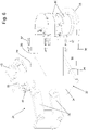
Figure 1 is a perspective view of a self-propelled vehicle for handling glass-sheet supporting racks realized according to the teachings of the present invention, with parts removed for clarity's sake; -
Figure 2 is a side view of the self-propelled vehicle illustrated inFigure 1 , with parts in section and with parts removed for clarity's sake; -
Figure 3 is a side view of the front part of the self-propelled vehicle illustrated inFigures 1 and2 , in a first operating configuration and with parts in section and parts removed for clarity's sake; -
Figure 4 is a side view of the front part of the self-propelled vehicle illustrated inFigures 1 and2 , in a second operating configuration and with parts in section and parts removed for clarity's sake; -
Figure 5 is a perspective view of the front part of the self-propelled vehicle illustrated in the previous figures, with parts in section and parts removed for clarity's sake; whereas -
Figure 6 is a perspective view of a component of the self-propelled vehicle illustrated inFigure 5 , with parts removed for clarity's sake. - With reference to
Figures 1 and2 , reference number 1 denotes, as a whole, a self-propelled vehicle for handling heavy loads, which can be advantageously used for handling, inside a general shed, warehouse, plant or other work area, single glass-sheet supporting racks 100 preferably of large dimensions, i.e. large rigid frames specifically structured for supporting glass sheets or packs of glass sheets of large dimensions, in an nearly vertical position. - In other words, the self-propelled vehicle 1 is preferably structured so as to be able to fork, lift, horizontally shift and finally rest back on the ground single glass-
sheet supporting racks 100 preferably with an A-shaped or L-shaped superstructure, with their possible load of glass sheets or packs of glass sheets. - Being a known equipment and easy to find in any plant for the production of glass sheets, the glass-
sheet supporting racks 100 won't be further described. - Clearly, the self-propelled vehicle 1 can advantageously be used also for handling in safety loading platforms adapted to support metal plates and/or other product of large dimensions.
- With reference to
Figures 1 and2 , the self-propelled vehicle 1 is oblong in shape and is provided with a plurality of ground-resting wheels. - More specifically, the self-propelled vehicle 1 is longitudinally divided into a front rack-supporting
section 2 and arear drive section 3, which are aligned one after the other along the vehicle longitudinal axis L, and are stably connected to each other by a mechanical assembly, which is structured so as to maintain the front rack-supportingsection 2 and therear drive section 3 always aligned with each other, astride of the vertical midplane of the vehicle, and simultaneously enables the front rack-supportingsection 2 to move freely with respect to therear drive section 3 in a substantially vertical direction, i.e. orthogonally to the vehicle longitudinal axis L. - The front rack-supporting
section 2 is adapted to fork, in a manner known per se, a glass-sheet supporting rack 100, and is provided with at least one pair of ground-restingwheels 4 preferably idle and non-steering, which are arranged in proximity to the front end of the self-propelled vehicle 1, on opposite sides of the vertical midplane of the vehicle, preferably in a substantially specular position with respect to the same midplane. - The
rear drive section 3, in turn, is adapted to tow/ push/horizontally move the front rack-supportingsection 2, and is provided with at least one pair of ground-restingwheels 5 preferably driving and steering, which are arranged in proximity to the rear end of the self-propelled vehicle 1, on opposite sides of the vertical midplane of the vehicle, preferably in a substantially specular position with respect to the same midplane. - The self-propelled vehicle 1 is thus preferably provided with at least two front ground-resting
wheels 4 and with at least two rear ground-restingwheels 5, which are located in pairs on opposite sides of the vertical midplane of the vehicle, substantially at the vertices of a rectangle or of an isosceles trapezoid. Preferably, the rear ground-restingwheels 5 are moreover driving and steering, whereas the front ground-restingwheels 4 are idle and non-steering. - In addition, the self-propelled vehicle 1 is moreover provided with a preferably hydraulically- or pneumatically- operated, lifting
apparatus 6 which is capable of varying/ adjusting, on command, the height of the front rack-supportingsection 2 relative to the ground, preferably while always maintaining the rack-supportingsection 2 parallel to itself and to the ground. - More specifically, with reference to
Figures 1 and2 , the front rack-supportingsection 2 comprises a largeoblong chassis 7 with a substantially U-shaped rigid structure, i.e. substantially horseshoe-shaped, which extends substantially parallel to the ground, i.e. horizontally, and is provided with two long longitudinal tines orbeams 8 that extend substantially parallel to the ground and to the vehicle longitudinal axis L, preferably in an nearly specular position on opposite sides of the vertical midplane of the vehicle. - Preferably, the two longitudinal tines or
beams 8 moreover have a box-shaped structure. - The two
longitudinal beams 8 form/delimit between each other a large oblong and rectilinear central slot orcompartment 9, which extends parallel to the vehicle longitudinal axis L, substantially astride of the vertical midplane of the vehicle, is open at the front and is finally dimensioned so as to accommodate therein, or rather to fork, a glass-sheet supporting rack 100. - The front ground-resting
wheels 4 are preferably located in proximity to the front/distal ends of the twolongitudinal beams 8 ofchassis 7, and are oriented parallel to the vehicle longitudinal axis L. In other words, the front ground-restingwheels 4 are arranged with their own rotation axis substantially perpendicular to the vertical midplane of the vehicle. - The rear part of the
oblong chassis 7, in turn, is stably connected to therear drive section 3 preferably by a swing-arms linkage 10, which enables theoblong chassis 7 to freely move with respect to therear drive section 3 in vertical direction, preferably while remaining always substantially parallel to itself. - The
lifting apparatus 6 is adapted to vary/adjust, on command, the height from the ground h of theoblong chassis 7, or rather of the two longitudinal tines orbeams 8, preferably while maintaining the two longitudinal tines orbeams 8 always substantially parallel to themselves and/or to the ground. - More specifically, the
lifting apparatus 6 is adapted to vary, on command, the height from the ground h of theoblong chassis 7 between a minimum value (seeFigure 3 ) in which the twolongitudinal beams 8 are preferably substantially grazing the ground, and a maximum value in which thelongitudinal beams 8 are preferably lifted from the ground by at least 50 cm (centimeters). - With reference to
Figure 1 , in addition eachlongitudinal beam 8 is preferably structured so as to be able to slidingly couple with the plate-like base 101 of the glass-sheet supporting rack 100, so as to support/sustain the glass-sheet supporting rack 100 when theoblong chassis 7 lifts and reaches the maximum distance from the ground. - In other words, the
oblong chassis 7 is structured so as to be able to fork thebase 101 of a glass-sheet supporting rack 100 oriented parallel to the vehicle longitudinal axis L, slidingly coupling to thesame base 101. - More specifically, the
oblong chassis 7 is preferably provided, inside the oblong central slot orcompartment 9, with a pair of oblong and plate-like protruding longitudinal shelves, which extend cantilevered towards the vertical midplane of the vehicle, each one from the inner lateral side of a respectivelongitudinal beam 8, while remaining substantially parallel to the ground, i.e. while remaining substantially horizontal. - Preferably, the two longitudinal shelves are moreover substantially coplanar to each other. In other words, the two longitudinal shelves extend cantilevered inside the oblong central slot or
compartment 9, one towards the other. - The protruding longitudinal shelves of the two
longitudinal beams 8 ofchassis 7 are adapted to slidingly couple to the plate-like base 101 of the glass-sheet supporting rack 100, so as to be able to hold/prop the glass-sheet supporting rack 100. - With reference to
Figures 2 ,3 and 4 , thelifting apparatus 6, on the other hand, is preferably interposed between theoblong chassis 7, or rather thelongitudinal beams 8, and the front ground-restingwheels 4. Moreover, thelifting apparatus 6 is preferably additionally interposed between theoblong chassis 7 and the swing-arms linkage 10. - More specifically, the
vehicle lifting apparatus 6 preferably comprises a pair of swinging-arm suspensions 12, which are interposed between the front/distal ends of the twolongitudinal beams 8 and the beneath-located ground-restingwheels 4. - Preferably, each swinging-
arm suspension 12 is furthermore housed inside the relativelongitudinal beam 8. - More specifically, each swinging-
arm suspension 12 preferably comprises: a swingingarm 13, which is pivoted like a rocker-arm on the correspondinglongitudinal beam 8 of theoblong chassis 7, in proximity to the distal end of the same beam, so as to be able to rotate/oscillate about a transversal rotation axis A that is substantially horizontal and at same time also perpendicular to the vehicle longitudinal axis L, i.e. substantially perpendicular to the vertical midplane of the vehicle; and a hydraulic orpneumatic cylinder 14 that is interposed between the swingingarm 13 and the body of thelongitudinal beam 8, and is capable of varying the inclination/angular position of the swingingarm 12 with respect to the vertical. - The ground-resting
wheel 4 is preferably located at the free/bottom end of the swingingarm 13. - In the example shown, in particular, the front/distal end of each
longitudinal beam 8 rests on the ground preferably via two idle and non-steering ground-restingwheels 4, which are aligned with and substantially coplanar to each other and are fixed in axially rotatable and idle manner to asmall subframe 15 that, in turn, is hinged to the bottom end of theswinging arm 13. - Clearly, in a different embodiment, the front/distal end of each
longitudinal beam 8 could rest on the ground via one single idle and non-steering ground-resting wheel 4. - The front rack-supporting
section 2, therefore, is preferably provided with two swingingarms 13 that are arranged in a substantially specular position on opposite sides of the vertical midplane of the vehicle, and are pivoted like a rocker-arm on the twolongitudinal beams 8 of thechassis 7, so as to be able to separately rotate/swing about a common transversal rotation axis A, while remaining both locally substantially parallel to the vertical midplane of the vehicle. - Preferably, the
lifting apparatus 6 furthermore comprises a pneumatic or hydraulic distributor (not visible in the figures) which controls the inflow of the pressurized fluid at inlet of the hydraulic orpneumatic cylinders 14 of the two swinging-arm suspensions 12, so as to control/vary the inclination of the two swingingarms 13 with respect to the vertical, and thus be able to adjust on command the height from the ground of the front/distal ends of the twolongitudinal beams 8 of theoblong chassis 7. - With reference to
Figures 1 and2 , preferably the front rack-supportingsection 2 is moreover also provided with at least one pair of preferably pneumatically- or hydraulically- operated, movable load-lockingarms 16 that are mounted cantilevered on thelongitudinal beams 8 of theoblong chassis 7, on opposite sides of the vertical midplane of the vehicle and of the central slot orcompartment 9, and are capable of moving, on command, each one with respect to the correspondinglongitudinal beam 8, from and towards the vertical midplane of the vehicle, so as to bring their own distal/free end in abutment against the load of the glass-sheet supporting rack 100 temporarily accommodated in the central slot orcompartment 9. - More specifically, the movable load-locking
arms 16 are preferably arranged in pairs in a substantially specular position, on opposite sides of the vertical midplane of the vehicle. Moreover, each movable load-lockingarm 16 preferably extends cantilevered upwards from the upper part of the correspondinglongitudinal beam 8, and is preferably pivotally joined to the correspondinglongitudinal beam 8 so as to be able to move in a swinging manner from and towards the vertical midplane of the vehicle, rotating about a reference axis preferably substantially parallel to the vehicle longitudinal axis L. - Preferably, each movable load-locking
arm 16 moreover has an articulated parallelogram structure. - In the example shown, in particular, the front rack-supporting
section 2 is preferably provided with three pairs of opposite load-lockingarms 16, suitably spaced along the twolongitudinal beams 8 of theoblong chassis 7. - With reference to
Figures 1 and2 , in turn, therear drive section 3 preferably comprises a supportingbody 17, separate and distinct from theoblong chassis 7, which is arranged astride of the vertical midplane of the vehicle, and is preferably stably connected to the rear part of theoblong chassis 7 by the swing-arms linkage 10. - The rear ground-resting
wheels 5 are fixed to the supportingbody 17 on opposite sides of the vertical midplane of the vehicle, preferably in a substantially specular position with respect to such midplane, with the capability of rotating about their respective substantially vertical steering axes. - Additionally, the
rear drive section 3 comprises: a preferably electrically- or hydraulically- operated, steering assembly (not visible in the figures) that controls the orientation/angle ofwheels 5 with respect to the supportingbody 17 and to the vehicle longitudinal axis L; and an engine assembly preferably of electric type (not visible in the figures), which is located on the supportingbody 17 and is adapted to drive into rotation therear wheels 5. - More specifically, in the example shown the two ground-resting
wheels 5 are preferably placed on a pair of swiveling wheel hubs (not visible in the figures), which are fixed on the supportingbody 17 with the capability of freely rotating about respective substantially vertical rotation axes. The steering assembly, in turn, preferably includes two small electric servomotors that are mechanically connected each to a respective swiveling wheel hub, and are capable of rotating on command the same swiveling wheel hub about its vertical rotation axis, so as to vary/control the angular position of the wheel hub with respect to the vehicle longitudinal axis L. - In turn, the engine assembly preferably comprises two large electric motors separate and independent to each other, that are adapted to drive into rotation each a respective ground-
resting wheel 5, and are preferably placed each on a respective swiveling wheel hub. - Preferably, the
rear drive section 3 of the vehicle is additionally also provided with a driver'scab 18 that is dimensioned for accommodating the driver of the vehicle (i.e. the person driving the self-propelled vehicle 1), and is preferably located/obtained on the top of the supportingbody 17. The steering wheel, the hand lever that controls the rotation speed of therear wheels 5, and the other manually-operated control members necessary for driving the self-propelled vehicle 1 are preferably located inside the driver'scab 18. - With reference to
Figure 2 , the swing-arms linkage 10, in turn, is preferably interposed between the supportingbody 17 of therear drive section 3 and the rear part of theoblong chassis 7. - Preferably the swing-
arms linkage 10 furthermore comprises: a pair of main swingingarms 20, which extend parallel to the vertical midplane of the vehicle, in a substantially specular position on opposite sides of the vertical midplane of the vehicle, and are aligned each to a respectivelongitudinal beam 8 of theoblong chassis 7; and a pair of secondary swingingarms 21 that extend parallel to the vertical midplane of the vehicle, in a substantially specular position on opposite sides of the vertical midplane of the vehicle, and are each arranged next to a respective main swingingarm 20. - The main swinging
arms 20 preferably have an end hinged to the supportingbody 17 of therear drive section 3 so as to be able to rotate with respect to the latter parallel to the vertical midplane of the vehicle, and are further pivoted like a rocker-arm on theoblong chassis 7 of the front rack-supportingsection 2, so as to additionally be able to rotate with respect to the latter always remaining parallel to the vertical midplane of the vehicle. - Preferably, the two main swinging
arms 20 are moreover connected in a rigid manner to each other, so as to rotate with respect to the supportingbody 17 ofrear drive section 3 while remaining always parallel to and aligned with each other. - In the example shown, in particular, the swing-
arms linkage 10 preferably includes a large transversalrectilinear shaft 22, which is arranged astride of the vertical midplane of the vehicle, with its longitudinal axis B substantially perpendicular to the same vertical midplane, and is housed in therear drive section 3, or rather in the supportingbody 17, with the capability of freely rotating about its longitudinal axis B. The ends of the two main swingingarms 20 are each preferably keyed in an angularly rigid manner onto a respective axial end of thetransversal shaft 22. - Whereas, the secondary swinging
arms 21 preferably have the two ends pivotally joined in rotatable manner one to the supportingbody 17 of therear drive section 3 and the other to theoblong chassis 7 of the front rack-supportingsection 2, so as to form an articulated-parallelogram structure each one with the adjacent main swingingarm 20. - With reference to
Figure 2 , preferably thelifting apparatus 6 additionally also comprises two supplementary single-acting or double-acting hydraulic orpneumatic cylinders 24, which are interposed between the main swingingarms 20 of swing-arms linkage 10 and the body of thelongitudinal beam 8, and are adapted to vary the inclination of the main swingingarms 20 with respect to the vertical, so as to adjust, on command, the height from the ground of the rear part of theoblong chassis 7. - Preferably, the two supplementary hydraulic or
pneumatic cylinders 24 are furthermore housed each inside a respectivelongitudinal beam 8 ofchassis 7. - Clearly, in a simplified version, the
lifting apparatus 6 could comprise a single supplementary hydraulic orpneumatic cylinder 24. - Preferably, the
lifting apparatus 6 moreover also comprises two oblong in shape,longitudinal coupling rods 25 that are housed each inside a respectivelongitudinal beam 8, and are adapted to connect each the swingingarm 13 of a respective front swinging-arm suspension 12 with the corresponding and facing main swingingarm 20 of the swing-arms linkage 10. - The two
longitudinal coupling rods 25 force the swingingarms 13 of the two front swinging-arm suspensions 12 to rotate in a synchronized manner with the main swingingarms 20 of the swing-arms linkage 10. - Preferably, the hydraulic or pneumatic distributor of lifting apparatus 6 (not visible in the figures) is capable of controlling the inflow of pressurized fluid also to the hydraulic or
pneumatic cylinders 24, so as to lift or lower theoblong chassis 7 as desired, preferably while maintaining thelongitudinal beams 8 parallel to the ground. - With reference to Figures from 1 to 6, in addition the self-propelled vehicle 1 also comprises: a
laser scanner 30 located on the front part of theoblong chassis 7; and asupport assembly 31 that firmly connects thelaser scanner 30 to theoblong chassis 7, directly holds/supports thelaser scanner 30, and is capable of moving thelaser scanner 30 vertically with respect to thechassis 7. - Preferably, the self-propelled vehicle 1 is moreover provided with an electronic control device (not shown) which is electronically connected to the
laser scanner 30, and is preferably programmed/configured to help the driver in the maneuvers for approaching the glass-sheet supporting rack 100 to be handled and/or for driving the self-propelled vehicle 1 in a completely autonomous manner, i.e. without the presence of the driver. - More specifically, the
laser scanner 30 is preferably located at the front end of one of the twolongitudinal beams 8, and is adapted to control/scan, preferably continuously, the space in front of/facing the self-propelled vehicle 1, preferably for identifying any objects or obstacles located in proximity to the self-propelled vehicle 1 and/or for identifying the position and/or the orientation of the glass-sheet supporting rack 100 to be handled. - The
laser scanner 30 is an electronic component already known and widely used in the field of self-propelled transporters for handling glass-sheet supporting racks, is preferably fixed to supportassembly 31 with its detection plane substantially parallel to the ground, i.e. in a substantially horizontal position, and it won't be further described. - The
support assembly 31, on the other hand, is adapted to lift and lower thelaser scanner 30 with respect to theoblong chassis 7 so as to vary/adjust the height from the ground of thelaser scanner 30, preferably while maintaining the detection plane of thelaser scanner 30 always substantially parallel to itself. - Preferably the
support assembly 31 is furthermore capable of synchronizing the vertical shifts of thelaser scanner 30 with the height variations of thechassis 7, so as to maintain the height from the ground of thelaser scanner 30 around a predetermined optimum value, regardless of the height from the ground h of theoblong chassis 7. - More specifically, with reference to Figures from 1 to 4, the
laser scanner 30 is preferably placed underneath thelongitudinal beam 8, approximately at the front end of the beam. - The
support assembly 31, in turn, is preferably structured so as to move thelaser scanner 30 vertically relative to theoblong chassis 7 between a fully raised position (seeFigure 3 ) in which thelaser scanner 30 is preferably at least partially housed/embedded inside thelongitudinal beam 8, or is anyway at the minimum distance from thelongitudinal beam 8; and a fully lowered position (seeFigure 4 ) in which thelaser scanner 30 is suspended spaced beneath thelongitudinal beam 8, at a predetermined maximum distance from the relativelongitudinal beam 8. Preferably such maximum distance moreover ranges between 20 and 30 cm (centimeters). - Preferably, the
support assembly 31 is furthermore structured so as to raise thelaser scanner 30 together with theoblong chassis 7, when the height from the ground h of the twolongitudinal beams 8 exceeds a given maximum value (for example 40 cm) . - More specifically, with reference to Figures from 1 to 6, the
laser scanner 30 is preferably fixed to an intermediate supportingstructure 32 that, in turn, is firmly fixed to theoblong chassis 7 and is moreover capable of moving with respect to theoblong chassis 7 in an approximately vertical direction, so as to be able to shift up and down thelaser scanner 30 relative to thelongitudinal beam 8 immediately above. - In addition to the intermediate supporting
structure 32, thesupport assembly 31 preferably also includes a drivingdevice 33, which is capable of moving the intermediate supportingstructure 32 with respect to thechassis 7 in a coordinated manner with thelifting apparatus 6. - More specifically, the driving
device 33 is preferably adapted to move the intermediate supportingstructure 32 and thelaser scanner 30 integral thereto with respect to theoblong chassis 7, so as to maintain the height from the ground of thelaser scanner 30 around said given optimum value. - With reference to
Figures 3, 4 ,5 and6 , in the example shown, in particular, thesupport assembly 31 is preferably located on thelongitudinal beam 8, between the front end of thelongitudinal beam 8 and the swinging-arm suspension 12 of the samelongitudinal beam 8, and is preferably also at least partially housed/recessed inside the samelongitudinal beam 8. - Moreover, the intermediate supporting
structure 32 ofsupport assembly 31 preferably consists of, or anyway includes a tilting framework preferably with an articulated parallelogram geometry, which is interposed between thelaser scanner 30 and theoblong chassis 7, and is pivotally joined to theoblong chassis 7 so as to move in a swinging manner/oscillate on a swinging plane that is preferably substantially vertical and optionally also substantially parallel to the midplane of the vehicle. - Preferably the tilting framework is furthermore housed inside the
longitudinal beam 8. - The driving
device 33 ofsupport assembly 31, in turn, is structured so as to rotate said tilting framework upwards and downwards in a swinging manner, so as to vary the distance of thelaser scanner 30 from the ground and/or from thelongitudinal beam 8 immediately above. - Moreover, the driving
device 33 is preferably also structured so as to synchronize the upward and downward movements of the tilting framework with the rotations of the swingingarm 13 of the adjacent swinging-arm suspension 12. - With reference to
Figures 5 and6 , in the example shown, in particular, the intermediate supportingstructure 32 ofsupport assembly 31, or rather the tilting framework, preferably comprises: a plate-like bracket 34 arranged in a substantially vertical position, inside thelongitudinal beam 8; two pairs of swingingarms 35 that are parallel to the vertical midplane of the vehicle, and connect the two vertical sides of the plate-like bracket 34 with the two larger vertical walls of thelongitudinal beam 8, forming an articulated parallelogram linkage; and a preferably substantially straight, rigid protrudingstem 36 that extends cantilevered from the plate-like bracket 34, preferably while remaining substantially parallel to the ground, and directly supports thelaser scanner 30. - More specifically, in the example shown, the
rigid stem 36 extends cantilevered from the plate-like bracket 34 preferably towards the outside of thelongitudinal beam 8 on the opposite side with respect to thecentral compartment 9, and thelaser scanner 30 is firmly fixed to the distal end of therigid stem 36 preferably viaelastic fixing members 37. - Preferably, the tilting framework finally also includes an protruding
protection plate 38 that extends cantilevered from the plate-like bracket 34 substantially parallel to the ground and spaced underneath therigid stem 36, and extends up to covering and protecting the bottom part of thelaser scanner 30. - With reference to
Figures 3, 4 ,5 and6 , in turn, the drivingdevice 33 preferably mechanically connects the intermediate supportingstructure 32, or rather the tilting framework, to the swingingarm 13 of the immediately adjacent swinging-arm suspension 12. - More specifically, the driving
device 33 preferably consists of, or anyway includes, a gearing cascade or other mechanism that transmits the rotary motion of the swingingarm 13 of the swinging-arm suspension 12 directly to the immediately adjacent, intermediate supportingstructure 32, or rather to the tilting framework. - In the example shown, in particular, the gearing cascade preferably comprises: a
gear wheel 40 that lies substantially on the swinging plane of the tilting framework, and is fixed in axially rotatable manner to at least one of the two larger vertical walls oflongitudinal beam 8, spaced above the tilting framework; and a connectingchain 41 that is centrally wound in a saddled manner to thegear wheel 40, and has the two ends rigidly fixed one to the tilting framework, preferably at the plate-like bracket 34, and the other to the swingingarm 13 of the immediately adjacent swinging-arm suspension 12. - With reference to
Figures 3 and 4 , the connectingchain 41 lowers and raises the tilting framework each time the swingingarm 13 of swinging-arm suspension 12 is rotated by the hydraulic orpneumatic cylinder 14, respectively, clockwise and counterclockwise. - Preferably, the driving
device 33, or rather the gearing cascade, additionally also comprises anelastic member 44, which is interposed between the tilting framework, or rather the plate-like bracket 34, and theoblong chassis 7, and is adapted to pull downwards said tilting framework in elastic manner. - In addition, the
support assembly 31 is preferably also provided with amechanical travel stop 45, that limits the downward movement of the intermediate supportingstructure 32, or rather the downward rotation of the tilting framework, so as to prevent thedriving device 33, or rather the gearing cascade, from lowering thelaser scanner 30 below a given maximum limit with respect to thelongitudinal beam 8. - Preferably, the
support assembly 31 is finally also provided with aposition sensor 46 that detects when the intermediate supportingstructure 32, or rather the tilting framework, rests on themechanical travel stop 45. - General operation of the self-propelled vehicle 1 is easily inferable from the foregoing, and thus does not require any further explanations.
- As regard instead to the
support assembly 31, such assembly maintains thelaser scanner 30 firmly attached/ suspended beneath thelongitudinal beam 8 of theoblong chassis 7, but is capable of varying/adjusting the distance of thelaser scanner 30 from thechassis 7, so as to stably maintain thelaser scanner 30 at a predetermined and substantially constant distance from the ground beneath. - Moreover, the
support assembly 31 is capable of maintaining the distance from the ground of thelaser scanner 30 around an optimum value (for example 10-15 cm), which is preferably less than or equal to the maximum height from the ground required by the homologation regulations for thelaser scanners 30 that also perform the anti-collision function in the vehicles provided with autonomous drive electronic systems. - Finally, if the height from ground h of the
longitudinal beams 8 of theoblong chassis 7 exceeds a predetermined limit value (for example 40 cm), thesupport assembly 31 hooks thelaser scanner 30 to theoblong chassis 7 so as to follow the moments of the latter in vertical diversion. - In this manner, the
laser scanner 30 can be temporarily brought to a height from ground such as to prevent the impact with objects or obstacles of large dimensions. - The advantages connected to the presence of the
support assembly 31 are evident. - The
support assembly 31 succeeds in maintaining thelaser scanner 30 at a height from the ground (for example 15 cm) that meets the homologation regulations for thelaser scanners 30 with anti-collision function, but prevents thelaser scanner 30 from accidentally bumping against any obstacles present along the path of the self-propelled vehicle 1. - Moreover, the capability of moving the
laser scanner 30 vertically beneath thelongitudinal beam 8 of theoblong chassis 7 prevents the glass-sheet supporting rack 100 at the moment located in thecentral compartment 9, from covering/limiting somehow the visual field of thelaser scanner 30. - Finally, being now fixed to the
support assembly 31, thelaser scanner 30 is completely isolated from the vibrations produced by thefront wheels 4 during the rolling, with all the advantages that this entails for the electronics of the device which is known to be very sensitive to vibrations. The hydraulic accumulators of the swinging-arm suspensions 12, in fact, prevent the vibrations produced by thewheels 4 from being transmitted to theoblong chassis 7. - It is finally clear that modifications and variants may be made to the self-propelled vehicle 1, without however departing from the scope of the present invention.
- For example, the
laser scanner 30 may be replaced by another type of optoelectronic sensing device. - Moreover, the self-propelled vehicle 1 may additionally be provided with one or more surveillance cameras and/or with one or more additional laser scanners that are suitably distributed on the front and/or rear part of the
oblong chassis 7. - Finally, in a more sophisticated not-shown embodiment, the driving
device 33 ofsupport assembly 31 can be completely independent of thelifting apparatus 6. - More specifically, the driving
device 33 may comprise an electromechanical actuator that moves the intermediate supportingstructure 32 upwards and downwards; and an electronic unit that controls the electromechanical actuator on the basis of the signals coming from a distance measuring sensor which is capable of detecting in real time the distance of thelaser scanner 30 and/or of thelongitudinal beam 8 from the ground.
Claims (16)
- A self-propelled vehicle (1) for handling glass-sheet supporting racks (100) of the type comprising a front rack-supporting section (2) and a rear drive section (3), both provided with ground-resting wheels and stably connected to each other by a mechanical assembly (10) that enables the front rack-supporting section (2) to move vertically with respect to the rear drive section (3);the front rack-supporting section (2) comprising: an oblong chassis (7) which is movable vertically with respect to the rear drive section (3), and is provided with two longitudinal beams (8) that extend parallel to the vehicle longitudinal axis (L) and delimit a large central compartment (9) open at the front and adapted to accommodate a glass-sheet supporting rack (100); at least one pair of front ground-resting wheels (4) that are located underneath said longitudinal beams (8); and at least one optoelectronic sensing device (30) which is adapted to control/scan the space in front of/facing the vehicle;the self-propelled vehicle (1) being characterised in that the optoelectronic sensing device (30) is fixed to said oblong chassis (7) via a support assembly (31) that directly holds/supports said optoelectronic sensing device (30) and is capable of moving said optoelectronic sensing device (30) vertically relative to the oblong chassis (7).
- The self-propelled vehicle according to Claim 1, wherein said support assembly (31) comprises an intermediate supporting structure (32) which is interposed between said optoelectronic sensing device (30) and said oblong chassis (7), and is capable of moving relative to the oblong chassis (7) so as to move up and down the optoelectronic sensing device (30) relative to said oblong chassis (7).
- The self-propelled vehicle according to Claim 2, wherein said support assembly (31) additionally comprises driving means (33) capable of moving the intermediate supporting structure (32) relative to the oblong chassis (7) .
- The self-propelled vehicle according to any one of the preceding claims, characterised by additionally comprising a lifting apparatus (6) that is adapted to vary the height of the oblong chassis (7) from the ground (h) while keeping the two longitudinal beams (8) substantially parallel to themselves; said support assembly (31) being adapted to move the intermediate supporting structure (32) with respect to the oblong chassis (7) in a coordinated manner with said lifting apparatus (6).
- The self-propelled vehicle according to any one of the preceding claims, wherein the optoelectronic sensing device (30) is located at the front end of one of the two longitudinal beams (8) of the oblong chassis (7).
- The self-propelled vehicle according to any one of the preceding claims, wherein the optoelectronic sensing device (30) is located beneath one of the two longitudinal beams (8) of the oblong chassis (7).
- The self-propelled vehicle according to Claim 6, wherein said support assembly (31) is adapted to move the optoelectronic sensing device (30) vertically relative to the oblong chassis (7) between a fully raised position in which the optoelectronic sensing device (30) is at the minimum distance from the longitudinal beam (8); and a fully lowered position in which the optoelectronic sensing device (30) is suspended/spaced beneath the longitudinal beam (8), at a predetermined maximum distance from said longitudinal beam (8).
- The self-propelled vehicle according to any one of Claims from 2 to 7, wherein the intermediate supporting structure (32) includes a tilting framework (34, 35, 26, 37, 38) that is interposed between the optoelectronic sensing device (30) and the oblong chassis (7), and is pivotally joined to the oblong chassis (7) so as to move in a swinging manner on a substantially vertical swinging plane.
- The self-propelled vehicle according to Claim 8, wherein said tilting framework (34, 35, 26, 37, 38) has an articulated parallelogram geometry.
- The self-propelled vehicle according to Claim 8 or 9, wherein the swinging plane of said tilting framework (34, 35, 26, 37, 38) is substantially parallel to the vertical midplane of the vehicle.
- The self-propelled vehicle according to any one of the preceding claims, wherein the two longitudinal beams (8) of the oblong chassis (7) are connected to the beneath-located front ground-resting wheels (4) by corresponding swinging-arm suspensions (12).
- The self-propelled vehicle according to Claim 11, wherein the swinging arm suspension (12) comprises: a swinging arm (13) which is pivoted like a rocker-arm on the corresponding longitudinal beam (8) so as to rotate/swing about a rotation axis (A) substantially perpendicular to the vertical midplane of the vehicle; and a hydraulic or pneumatic cylinder (14), which is interposed between the swinging arm (13) and the body of the longitudinal beam (8), and is capable of varying, on command, the inclination/ angular position of the swinging arm (12).
- The self-propelled vehicle according to Claim 12, wherein the driving means (33) of the support assembly (31) mechanically connect the intermediate supporting structure (32) to the swinging arm (13) of the swinging-arm suspension (12) .
- The self-propelled vehicle according to Claim 13, wherein the driving means (33) of the support assembly (31) comprise a gearing cascade (40, 41) that transmits the rotary motion of the swinging arm (13) of the swinging-arm suspension (12) directly to said intermediate supporting structure (32).
- The self-propelled vehicle according to any one of the preceding claims, wherein the optoelectronic sensing device (30) is a laser scanner.
- The self-propelled vehicle according to any one of the preceding claims, wherein the rear part of the oblong chassis (7) is connected to the rear drive section (3) by means of a swing-arms linkage (10).
Applications Claiming Priority (1)
| Application Number | Priority Date | Filing Date | Title |
|---|---|---|---|
| IT102021000003494A IT202100003494A1 (en) | 2021-02-16 | 2021-02-16 | SELF-PROPELLED VEHICLE FOR THE HANDLING OF SLAB-HOLDER STANDS |
Publications (2)
| Publication Number | Publication Date |
|---|---|
| EP4043280A1 true EP4043280A1 (en) | 2022-08-17 |
| EP4043280B1 EP4043280B1 (en) | 2023-12-20 |
Family
ID=75769781
Family Applications (1)
| Application Number | Title | Priority Date | Filing Date |
|---|---|---|---|
| EP22157109.4A Active EP4043280B1 (en) | 2021-02-16 | 2022-02-16 | Self-propelled vehicle for handling glass-sheet supporting racks |
Country Status (3)
| Country | Link |
|---|---|
| US (1) | US20220258660A1 (en) |
| EP (1) | EP4043280B1 (en) |
| IT (1) | IT202100003494A1 (en) |
Families Citing this family (1)
| Publication number | Priority date | Publication date | Assignee | Title |
|---|---|---|---|---|
| IT202000015211A1 (en) * | 2020-06-24 | 2021-12-24 | Italcarrelli S P A | SELF-PROPELLED VEHICLE FOR THE HANDLING OF SLAB-HOLDER STANDS |
Citations (3)
| Publication number | Priority date | Publication date | Assignee | Title |
|---|---|---|---|---|
| JP2017061204A (en) * | 2015-09-24 | 2017-03-30 | シャープ株式会社 | Travel device |
| IT201800002718A1 (en) * | 2018-02-15 | 2019-08-15 | Italcarrelli S R L | SELF-PROPELLED VEHICLE FOR HANDLING SLAB-HOLDER STANDS |
| FR3086051A1 (en) * | 2018-09-13 | 2020-03-20 | Lohr Electromecanique | ON-BOARD SYSTEM AND LOADING HEIGHT MEASUREMENT METHOD |
Family Cites Families (26)
| Publication number | Priority date | Publication date | Assignee | Title |
|---|---|---|---|---|
| US2199392A (en) * | 1939-03-27 | 1940-05-07 | Dabrasky August | Vehicle |
| US2299150A (en) * | 1940-05-23 | 1942-10-20 | Gorton Pew Fisheries Company L | Transportation apparatus |
| US2518624A (en) * | 1946-10-11 | 1950-08-15 | Kraft Louis | Rack structure for glaziers' vehicles |
| US2974972A (en) * | 1957-12-23 | 1961-03-14 | Air Logistics Corp | Positioning trailer |
| US3153544A (en) * | 1962-02-01 | 1964-10-20 | Clark Equipment Co | Steering linkage for retractable wheels |
| US3322292A (en) * | 1965-08-30 | 1967-05-30 | Keith R Bogh | Portable hydraulic lifting device |
| US3372769A (en) * | 1966-04-29 | 1968-03-12 | Clark Equipment Co | Material handling vehicle |
| US3557893A (en) * | 1968-02-12 | 1971-01-26 | Webb Co Jervis B | Automatic and manually controlled vehicle |
| SE390806B (en) * | 1974-03-15 | 1977-01-24 | K W Berglund | TRANSPORT VEHICLES |
| US4538792A (en) * | 1983-07-08 | 1985-09-03 | The United States Of America As Represented By The Secretary Of The Air Force | Loading dolly |
| WO1994016918A1 (en) * | 1993-01-19 | 1994-08-04 | Nordlund K S N | U-frame vehicle |
| US5584639A (en) * | 1994-10-14 | 1996-12-17 | Walker, Jr.; Esler C. | Tow trailer for transporting pallets |
| US5667231A (en) * | 1995-09-14 | 1997-09-16 | Dakota Mfg. Co., Inc. | Trailer |
| US6139248A (en) * | 1996-06-21 | 2000-10-31 | Marinette Marine Corporation | Module transporter |
| DE29701147U1 (en) * | 1997-01-23 | 1997-03-27 | Hegla Fahrzeug Maschinenbau | Load securing system for a storage and transport rack for storing and / or transporting flat objects |
| US6135465A (en) * | 1998-04-03 | 2000-10-24 | Chapman/Leonard Studio Equipment | Camera dolly |
| US7004483B1 (en) * | 2001-06-28 | 2006-02-28 | Marble Crafters, Inc. | Cart for large slabs |
| US6910844B2 (en) * | 2001-07-01 | 2005-06-28 | William B. Trescott | Self-loading vehicle for shipping containers |
| DE102011018222B4 (en) * | 2011-04-19 | 2015-05-28 | Wirtgen Gmbh | Shunting device for mounting a replaceable milling device of a road construction machine |
| US8991529B2 (en) * | 2013-01-21 | 2015-03-31 | GM Global Technology Operations LLC | Self-motivated cargo pod |
| US9340373B2 (en) * | 2013-12-12 | 2016-05-17 | Integrated Automation Systems, Llc | Stackable insulated glass slat rack |
| US10179712B2 (en) * | 2016-08-10 | 2019-01-15 | Superior Handling Equipment, Llc | Towable dock-lift trailer |
| US10422179B2 (en) * | 2017-04-18 | 2019-09-24 | Goldfinch Brothers Inc. | Panel frame assembly, processing, transport, and installation system |
| FR3105953B1 (en) * | 2020-01-08 | 2022-01-21 | Commissariat Energie Atomique | VEHICLE COMPRISING A CHASSIS WITH A CONTROLLED VERTICAL POSITION, TO BE LOWERED INTO A LOW POSITION OF SUPPORT ON THE GROUND |
| IT202000015211A1 (en) * | 2020-06-24 | 2021-12-24 | Italcarrelli S P A | SELF-PROPELLED VEHICLE FOR THE HANDLING OF SLAB-HOLDER STANDS |
| MX2020011603A (en) * | 2020-10-30 | 2022-05-02 | Cruz Ungson Daniel Santa | Folding out stand for loading and transportation of flat glass. |
-
2021
- 2021-02-16 IT IT102021000003494A patent/IT202100003494A1/en unknown
-
2022
- 2022-02-15 US US17/672,210 patent/US20220258660A1/en not_active Abandoned
- 2022-02-16 EP EP22157109.4A patent/EP4043280B1/en active Active
Patent Citations (3)
| Publication number | Priority date | Publication date | Assignee | Title |
|---|---|---|---|---|
| JP2017061204A (en) * | 2015-09-24 | 2017-03-30 | シャープ株式会社 | Travel device |
| IT201800002718A1 (en) * | 2018-02-15 | 2019-08-15 | Italcarrelli S R L | SELF-PROPELLED VEHICLE FOR HANDLING SLAB-HOLDER STANDS |
| FR3086051A1 (en) * | 2018-09-13 | 2020-03-20 | Lohr Electromecanique | ON-BOARD SYSTEM AND LOADING HEIGHT MEASUREMENT METHOD |
Also Published As
| Publication number | Publication date |
|---|---|
| EP4043280B1 (en) | 2023-12-20 |
| IT202100003494A1 (en) | 2022-08-16 |
| US20220258660A1 (en) | 2022-08-18 |
Similar Documents
| Publication | Publication Date | Title |
|---|---|---|
| US5259721A (en) | Apparatus for transporting/mounting a building material | |
| EP3102529B1 (en) | Side-shift limiter | |
| EP0302890B1 (en) | Load lifting device load sensing | |
| EP4043280B1 (en) | Self-propelled vehicle for handling glass-sheet supporting racks | |
| EP2354078B1 (en) | Industrial truck | |
| EP3848326A1 (en) | Traveling robot | |
| JP6866839B2 (en) | Self-driving forklift | |
| US9994435B2 (en) | Forklift arrangement | |
| EP0931759B1 (en) | Lateral jib for vertical mast mobile elevating work platform | |
| US4906159A (en) | Freely positionable load carrying attachment for an automatic guided vehicle | |
| EP3724124B1 (en) | Crane with wheels having variable camber angle | |
| EP2275380A1 (en) | A vehicle lift | |
| EP3929032B1 (en) | Self-propelled vehicle for handling glass-sheet supporting racks | |
| EP2636631A1 (en) | Lifting device and method for lifting products | |
| IT201800002718A1 (en) | SELF-PROPELLED VEHICLE FOR HANDLING SLAB-HOLDER STANDS | |
| EP3838829B1 (en) | Operator vehicle with assisted centring device | |
| CN210001540U (en) | Double shelf fork truck | |
| JP2000289996A (en) | Lift vehicle, particularly, fork lift truck with positioning means | |
| EP3954578A1 (en) | Self-propelled vehicle for handling glass-sheet containers | |
| EP3228525B1 (en) | Powered steering trolley and transport vehicle provided with such trolley | |
| US20220259022A1 (en) | Industrial truck with detection devices on the forks | |
| EP3724125B1 (en) | Crane comprising a steering system | |
| EP3638613A1 (en) | A clamping device for a forklift and a forklift having such a clamping device | |
| EP3992063A1 (en) | Translifter for moving loads that are on a load platform | |
| JP6774926B2 (en) | Heavy load carrier |
Legal Events
| Date | Code | Title | Description |
|---|---|---|---|
| PUAI | Public reference made under article 153(3) epc to a published international application that has entered the european phase |
Free format text: ORIGINAL CODE: 0009012 |
|
| STAA | Information on the status of an ep patent application or granted ep patent |
Free format text: STATUS: THE APPLICATION HAS BEEN PUBLISHED |
|
| AK | Designated contracting states |
Kind code of ref document: A1 Designated state(s): AL AT BE BG CH CY CZ DE DK EE ES FI FR GB GR HR HU IE IS IT LI LT LU LV MC MK MT NL NO PL PT RO RS SE SI SK SM TR |
|
| STAA | Information on the status of an ep patent application or granted ep patent |
Free format text: STATUS: REQUEST FOR EXAMINATION WAS MADE |
|
| 17P | Request for examination filed |
Effective date: 20230214 |
|
| RBV | Designated contracting states (corrected) |
Designated state(s): AL AT BE BG CH CY CZ DE DK EE ES FI FR GB GR HR HU IE IS IT LI LT LU LV MC MK MT NL NO PL PT RO RS SE SI SK SM TR |
|
| P01 | Opt-out of the competence of the unified patent court (upc) registered |
Effective date: 20230331 |
|
| GRAP | Despatch of communication of intention to grant a patent |
Free format text: ORIGINAL CODE: EPIDOSNIGR1 |
|
| STAA | Information on the status of an ep patent application or granted ep patent |
Free format text: STATUS: GRANT OF PATENT IS INTENDED |
|
| INTG | Intention to grant announced |
Effective date: 20230710 |
|
| GRAS | Grant fee paid |
Free format text: ORIGINAL CODE: EPIDOSNIGR3 |
|
| GRAA | (expected) grant |
Free format text: ORIGINAL CODE: 0009210 |
|
| STAA | Information on the status of an ep patent application or granted ep patent |
Free format text: STATUS: THE PATENT HAS BEEN GRANTED |
|
| AK | Designated contracting states |
Kind code of ref document: B1 Designated state(s): AL AT BE BG CH CY CZ DE DK EE ES FI FR GB GR HR HU IE IS IT LI LT LU LV MC MK MT NL NO PL PT RO RS SE SI SK SM TR |
|
| REG | Reference to a national code |
Ref country code: GB Ref legal event code: FG4D |
|
| REG | Reference to a national code |
Ref country code: DE Ref legal event code: R096 Ref document number: 602022001321 Country of ref document: DE |
|
| REG | Reference to a national code |
Ref country code: CH Ref legal event code: EP |
|
| REG | Reference to a national code |
Ref country code: IE Ref legal event code: FG4D |
|
| PG25 | Lapsed in a contracting state [announced via postgrant information from national office to epo] |
Ref country code: GR Free format text: LAPSE BECAUSE OF FAILURE TO SUBMIT A TRANSLATION OF THE DESCRIPTION OR TO PAY THE FEE WITHIN THE PRESCRIBED TIME-LIMIT Effective date: 20240321 |
|
| REG | Reference to a national code |
Ref country code: LT Ref legal event code: MG9D |
|
| PG25 | Lapsed in a contracting state [announced via postgrant information from national office to epo] |
Ref country code: LT Free format text: LAPSE BECAUSE OF FAILURE TO SUBMIT A TRANSLATION OF THE DESCRIPTION OR TO PAY THE FEE WITHIN THE PRESCRIBED TIME-LIMIT Effective date: 20231220 |