EP4042933B1 - Annotation einer wellenfront - Google Patents
Annotation einer wellenfront Download PDFInfo
- Publication number
- EP4042933B1 EP4042933B1 EP22162146.9A EP22162146A EP4042933B1 EP 4042933 B1 EP4042933 B1 EP 4042933B1 EP 22162146 A EP22162146 A EP 22162146A EP 4042933 B1 EP4042933 B1 EP 4042933B1
- Authority
- EP
- European Patent Office
- Prior art keywords
- unipolar
- bipolar
- signal
- derivative
- amplitude
- Prior art date
- Legal status (The legal status is an assumption and is not a legal conclusion. Google has not performed a legal analysis and makes no representation as to the accuracy of the status listed.)
- Active
Links
Images


Classifications
-
- A—HUMAN NECESSITIES
- A61—MEDICAL OR VETERINARY SCIENCE; HYGIENE
- A61B—DIAGNOSIS; SURGERY; IDENTIFICATION
- A61B5/00—Measuring for diagnostic purposes; Identification of persons
- A61B5/24—Detecting, measuring or recording bioelectric or biomagnetic signals of the body or parts thereof
- A61B5/25—Bioelectric electrodes therefor
- A61B5/279—Bioelectric electrodes therefor specially adapted for particular uses
- A61B5/28—Bioelectric electrodes therefor specially adapted for particular uses for electrocardiography [ECG]
- A61B5/283—Invasive
-
- A—HUMAN NECESSITIES
- A61—MEDICAL OR VETERINARY SCIENCE; HYGIENE
- A61B—DIAGNOSIS; SURGERY; IDENTIFICATION
- A61B5/00—Measuring for diagnostic purposes; Identification of persons
- A61B5/24—Detecting, measuring or recording bioelectric or biomagnetic signals of the body or parts thereof
- A61B5/316—Modalities, i.e. specific diagnostic methods
- A61B5/318—Heart-related electrical modalities, e.g. electrocardiography [ECG]
- A61B5/339—Displays specially adapted therefor
-
- A—HUMAN NECESSITIES
- A61—MEDICAL OR VETERINARY SCIENCE; HYGIENE
- A61B—DIAGNOSIS; SURGERY; IDENTIFICATION
- A61B5/00—Measuring for diagnostic purposes; Identification of persons
- A61B5/24—Detecting, measuring or recording bioelectric or biomagnetic signals of the body or parts thereof
- A61B5/316—Modalities, i.e. specific diagnostic methods
- A61B5/318—Heart-related electrical modalities, e.g. electrocardiography [ECG]
- A61B5/346—Analysis of electrocardiograms
- A61B5/349—Detecting specific parameters of the electrocardiograph cycle
- A61B5/352—Detecting R peaks, e.g. for synchronising diagnostic apparatus; Estimating R-R interval
-
- A—HUMAN NECESSITIES
- A61—MEDICAL OR VETERINARY SCIENCE; HYGIENE
- A61B—DIAGNOSIS; SURGERY; IDENTIFICATION
- A61B5/00—Measuring for diagnostic purposes; Identification of persons
- A61B5/24—Detecting, measuring or recording bioelectric or biomagnetic signals of the body or parts thereof
- A61B5/316—Modalities, i.e. specific diagnostic methods
- A61B5/318—Heart-related electrical modalities, e.g. electrocardiography [ECG]
- A61B5/367—Electrophysiological study [EPS], e.g. electrical activation mapping or electro-anatomical mapping
-
- A—HUMAN NECESSITIES
- A61—MEDICAL OR VETERINARY SCIENCE; HYGIENE
- A61B—DIAGNOSIS; SURGERY; IDENTIFICATION
- A61B5/00—Measuring for diagnostic purposes; Identification of persons
- A61B5/68—Arrangements of detecting, measuring or recording means, e.g. sensors, in relation to patient
- A61B5/6846—Arrangements of detecting, measuring or recording means, e.g. sensors, in relation to patient specially adapted to be brought in contact with an internal body part, i.e. invasive
- A61B5/6867—Arrangements of detecting, measuring or recording means, e.g. sensors, in relation to patient specially adapted to be brought in contact with an internal body part, i.e. invasive specially adapted to be attached or implanted in a specific body part
- A61B5/6869—Heart
-
- A—HUMAN NECESSITIES
- A61—MEDICAL OR VETERINARY SCIENCE; HYGIENE
- A61B—DIAGNOSIS; SURGERY; IDENTIFICATION
- A61B5/00—Measuring for diagnostic purposes; Identification of persons
- A61B5/72—Signal processing specially adapted for physiological signals or for diagnostic purposes
- A61B5/7225—Details of analogue processing, e.g. isolation amplifier, gain or sensitivity adjustment, filtering, baseline or drift compensation
-
- A—HUMAN NECESSITIES
- A61—MEDICAL OR VETERINARY SCIENCE; HYGIENE
- A61B—DIAGNOSIS; SURGERY; IDENTIFICATION
- A61B5/00—Measuring for diagnostic purposes; Identification of persons
- A61B5/72—Signal processing specially adapted for physiological signals or for diagnostic purposes
- A61B5/7235—Details of waveform analysis
- A61B5/7239—Details of waveform analysis using differentiation including higher order derivatives
-
- A—HUMAN NECESSITIES
- A61—MEDICAL OR VETERINARY SCIENCE; HYGIENE
- A61B—DIAGNOSIS; SURGERY; IDENTIFICATION
- A61B5/00—Measuring for diagnostic purposes; Identification of persons
- A61B5/74—Details of notification to user or communication with user or patient; User input means
- A61B5/742—Details of notification to user or communication with user or patient; User input means using visual displays
- A61B5/743—Displaying an image simultaneously with additional graphical information, e.g. symbols, charts, function plots
-
- A—HUMAN NECESSITIES
- A61—MEDICAL OR VETERINARY SCIENCE; HYGIENE
- A61B—DIAGNOSIS; SURGERY; IDENTIFICATION
- A61B2505/00—Evaluating, monitoring or diagnosing in the context of a particular type of medical care
- A61B2505/05—Surgical care
-
- A—HUMAN NECESSITIES
- A61—MEDICAL OR VETERINARY SCIENCE; HYGIENE
- A61B—DIAGNOSIS; SURGERY; IDENTIFICATION
- A61B5/00—Measuring for diagnostic purposes; Identification of persons
- A61B5/24—Detecting, measuring or recording bioelectric or biomagnetic signals of the body or parts thereof
- A61B5/25—Bioelectric electrodes therefor
- A61B5/279—Bioelectric electrodes therefor specially adapted for particular uses
- A61B5/28—Bioelectric electrodes therefor specially adapted for particular uses for electrocardiography [ECG]
- A61B5/283—Invasive
- A61B5/287—Holders for multiple electrodes, e.g. electrode catheters for electrophysiological study [EPS]
-
- A—HUMAN NECESSITIES
- A61—MEDICAL OR VETERINARY SCIENCE; HYGIENE
- A61B—DIAGNOSIS; SURGERY; IDENTIFICATION
- A61B5/00—Measuring for diagnostic purposes; Identification of persons
- A61B5/68—Arrangements of detecting, measuring or recording means, e.g. sensors, in relation to patient
- A61B5/6846—Arrangements of detecting, measuring or recording means, e.g. sensors, in relation to patient specially adapted to be brought in contact with an internal body part, i.e. invasive
- A61B5/6847—Arrangements of detecting, measuring or recording means, e.g. sensors, in relation to patient specially adapted to be brought in contact with an internal body part, i.e. invasive mounted on an invasive device
- A61B5/6852—Catheters
Definitions
- This invention relates generally to electrocardiograph (ECG) signals, and specifically to a method for annotating the signals.
- ECG electrocardiograph
- Mapping and imaging of the electrical signals in the heart is typically based on combining local activation time (LAT), as indicated by a catheter's ECG signals, with the spatial position of the signals.
- LAT local activation time
- Such a method is used in the CARTO ® 3 System, produced by Biosense Webster of Diamond Bar, Ca.
- LAT is determined by the time difference between the reference annotation and the earliest activity in the bipolar signal in the mapping catheter channels.
- determining earliest activations in bipolar signals presents an ambiguity in LAT measurements since the earliest activation is a composition of the approaching fields from the two unipolar signals and does not necessarily correspond to the onset of the activity wave.
- US Patent Application Publication No. 2010/191132 describes a medical device and associated method which discriminate near-field and far-field events by sensing a bipolar signal and a unipolar signal at a tissue site, detecting an event in response to one of the bipolar and unipolar signals, and comparing an event feature determined from the bipolar signal to an event feature determined from the unipolar signal.
- Embodiments of the present invention use a wavefront annotation algorithm which acts to combine the properties of the two types of ECG signals - a bipolar signal together with one of its associated unipolar signals - to generate accurate signal annotations.
- the inventors have verified that the algorithm provides accurate annotations which are immune to far field interferences.
- the wavefront annotation algorithm provides automatic and reliable detection of annotation points that enable acquisition and annotation of numerous LAT points in a relatively short time.
- An embodiment of the present invention comprises receiving a bipolar signal from a pair of electrodes in proximity to a myocardium of a human subject.
- a unipolar signal is also received from a selected one of the pair of electrodes, and a local unipolar minimum derivative of the unipolar signal is computed.
- a time of occurrence of the unipolar minimum derivative is also computed.
- a bipolar derivative of the bipolar signal is computed, and a ratio of the bipolar derivative to the local unipolar minimum derivative is evaluated.
- the time of occurrence (of the unipolar minimum derivative) is identified as a time of activation of the myocardium.
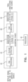
- Fig. 1 is a schematic block diagram of a wavefront annotation algorithm, according to an embodiment of the present invention.
- the algorithm inputs consist of a single bipolar signal and one of its unipolar signals, which are typically provided to a processor 20 operating the algorithm, following a low pass filter with a cut-off of 500 Hz and a power rejection filter. More detail of the operation of processor 20 is provided with reference to Fig. 17 below.
- the polarity of the unipolar signal is assumed to be known (i.e. it is derived from either a positive or a negative electrode).
- the processor may be a stand-alone processor, and/or a general purpose processor that is typically operating a computer.
- the algorithm comprises a number of stages, summarized here.
- a pre-processing stage 22 includes removal of baseline wander, low pass filtering and any order of differentiation.
- the removal of baseline wander includes removal of an additive low frequency signal that is an artifact and originates from various reasons such as mechanical catheter movement or respiration. This low frequency signal can alter the estimated derivative of the signals and therefore is typically removed.
- a feature extraction stage 24 uses the post-processed signals and extracts features for every candidate annotation.
- a first annotation detector stage 26 performs eliminations of candidate annotations based on a subset of features.
- a score is given to each candidate annotation based on its feature values. Only candidate annotations that surpass the score thresholds are considered as valid annotations, and the timing and features of these are used by the processor in further operations of the processor, such as generating a map of the candidate annotations.
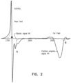
- Fig. 2 is an example of activity as measured by the bipolar signal and the unipolar positive electrode signal, according to an embodiment of the present invention.
- a graph 40 shows the bipolar signal; a graph 44 shows the unipolar signal.
- the sharp downward deflection on the left, in a region "A" is a near field activity which is concurrent in the unipolar and the bipolar signals.
- the unipolar signal changes, however, the bipolar activity is negligible.
- Embodiments of the present invention use multiple features of the signal similar to those exemplified above to assist in separating between local and far field activations. For example, in region A the unipolar amplitude and its rate are similar to the bipolar signal, while in region B the unipolar signal amplitude is much larger and its rate is much faster than the bipolar signal.
- stages 22 and 24 The purpose of these pre-processing and feature extraction stages is to remove and attenuate interferences in the unipolar and bipolar signals while maintaining and emphasizing those features of the signal that are used in subsequent stages. While for simplicity the actions described herein are assumed to occur in stages 22 and 24, it will be understood that at least some of these actions may occur in other stages of the algorithm.
- a characteristic that we want to retain is the morphology of activations, since it reflects slope changes. Characteristics that are typically discarded are the baseline-wander that acts as an additive signal that can corrupt the slope measurements and also high frequency noise. Stages 22 and 24 are divided into four sub-stages:
- the Unipolar pre-processing stage consists of applying the following steps in series:
- step 5 The derivative of step 5 is used as an input to a unipolar annotation detector-(Phase I) in first annotation detector stage 26 ( Fig. 1 ).
- the additional filtered signal output of step 4 is used for feature extraction stage 24 of the algorithm.
- the bipolar pre-processing stage consists of applying the following steps in series:
- the final output of the bipolar preprocessing stage (the bipolar derivative) is used as an input to the unipolar annotation detector-(Phase I) referred to above ( Fig. 1 ).
- Intra-cardiac (IC) signals may contain additive baseline wander signals arising from movement of the catheter, movement of the subject and respiration that changes the interface with the tissue (see Fig. 3 and its description below). These motion artifacts contain mostly low frequency components. However, the near field activity signal may also contain significant energy in these spectral bands. Therefore the conventional approach of removal by high pass IIR or FIR filter is problematic and can cause distortion and morphology changes to the IC signals. Consequently, the selected approach that we use is based on estimation of the baseline wander ( Fig. 3 ) and its subtraction from the signal.
- Fig. 3 is a graph illustrating baseline wander removal, according to an embodiment of the present invention.
- a unipolar signal 50 is originally contaminated by a low frequency artifact, contributing to the baseline wander.
- the purpose of the baseline estimation is to calculate the baseline which is then subtracted from the signal.
- a calculated baseline 54 has been overlaid on the unipolar signal.
- Baseline wander rejection is important since baseline wander can add noise to the estimate of the unipolar derivatives, and thus may affect the annotation detection.
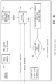
- the estimation of the baseline wander, and its subtraction from the original, is accomplished by removal of the near field activity using a series of two filters as is illustrated in Fig. 4 .
- Fig. 4 is a block diagram of a baseline wander removal system, according to an embodiment of the present invention.
- a median filter 60 typically having a window of 60 ms, is designed to remove the activities from the raw signal while an LPF 64, which in one embodiment is an 89 taps FIR Hanning filter with a typical cut-off of approximately 10 Hz, is designed to smooth out edges resulting from the median filter.
- LPF 64 which in one embodiment is an 89 taps FIR Hanning filter with a typical cut-off of approximately 10 Hz, is designed to smooth out edges resulting from the median filter.
- the baseline estimate is subtracted from the raw signal, by a process of negation 68 then summation 72, resulting in a signal free of baseline wander.
- Fig. 5 is a graph of two Gaussian filters, according to an embodiment of the present invention.
- the detection of sharp deflection points in the signal is based on the velocity of the signal, therefore a derivative approach is used.
- derivative functions act as a high pass filter, thus enhancing high frequency noise. Therefore, we use a smoothing function to decrease the noise in the derivative estimation.
- the smoothing function that we use are normalized zero mean Gaussian functions, comprising a unipolar Gaussian function 80 and a bipolar Gaussian function 84, illustrated in Fig. 5 .
- These unipolar and bipolar Gaussian filters have 90% of the energy in time windows of ⁇ 2 ms and ⁇ 1 ms respectively. Thus activations or approaching far fields at distances larger than these values are virtually ignored and do not affect the derivative value.
- Fig. 6 is a schematic block diagram of Annotation Detector-I stage 26;
- Fig. 7 is a graph of unipolar and bipolar signals, and their derivatives;
- Fig. 8 has graphs illustrating a first rejection phase of the annotation algorithm;
- Fig. 9 has graphs illustrating local and far field candidate annotations, according to embodiments of the present invention.
- Table I gives parameters used in the detector, and corresponding acronyms in the block diagram.
- Table I Parameter Acronym Smoothed Unipolar Derivative S-Uni Smoothed Unipolar Derivative Threshold Th-Uni Smoothed Bipolar Derivative S-Bip Smoothed Bipolar Derivative Threshold Th-Bip S ⁇ Bip S ⁇ Uni R
- Fig. 7 shows an example of a bipolar slope of zero around a unipolar annotation.
- the graphs show a unipolar distal signal 100, its derivative 102, its local activation (A) as well as a bipolar signal 104, and its derivative 106. Notice that at the unipolar deflection point (A) the bipolar derivative is almost zero and it is not indicative of the large change in bipolar amplitude.
- Fig. 8 has graphs illustrating a first rejection stage of the annotation algorithm of Fig. 1 .
- a top graph 110 shows the unipolar signal and a bottom graph 114 shows its smoothed derivative.
- Black dots 118 are minima values in the derivative signal below a threshold value and will be further considered as possible annotation points while grey dots 122 mark minima value above the threshold that will be rejected.
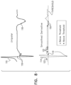
- Fig. 9 illustrates separation between local (A) and far field (B) candidate annotations using the bipolar and unipolar derivative ratio feature described herein.
- the figure shows unipolar 130 and bipolar 132 signals, and unipolar 136 and bipolar 138 derivatives.
- unipolar derivative changes are accompanied by a bipolar derivative change as illustrated by a 2 ms activity window 140.
- this is not the case in the far field derived deflection (B), as illustrated by window 144, thus the ratio between the change in the bipolar and unipolar slope for the far field case will be below the required ratio threshold.
- the inputs for the annotation detector-I block are the relevant unipolar signal derivative under test, its polarity and its smoothed bipolar derivative.
- the outputs of the block are the annotation indexes and their slope value (the unipolar derivative value at the annotation index).
- the slope value acts as the score of the annotation.
- the deflection points in the downslopes of the unipolar signal are detected, in blocks 90 and 92, by finding the minima points below a threshold (typically -0.01 mv/ms), see also Fig. 8 . Activities typically satisfy this condition in addition to two others:
- #1 and #2 are evaluated in blocks 94 and 96, and in a decision 98.
- the bipolar derivative value (S-bip) is computed differently for positive and negative electrodes.
- a positive electrode it is the minimal value within a 2 ms time window
- a negative electrode it is the negative value of the maximal value within that time window.
- the reason for using a time window and not the derivative at the annotation point is that in certain pathologies and/or orientations (of the catheter and the wave propagation direction) the bipolar signal at a given point can be small or even zero since the time delay of activities between unipolar activations can cancel out ( Fig. 7 ).
- the value is calculated differently for positive and negative electrodes since the tip activity at the positive electrode is registered as a downslope in the bipolar signal, while activity at the negative electrode is registered as an upslope in the bipolar signal.
- the ratio between the unipolar and the bipolar derivatives may also be used as a classification criterion since this criterion can distinguish between near field and far field activity.
- this criterion can distinguish between near field and far field activity.
- near field activity at least some of the downslope activity is typically represented in the bipolar signal, while in far field cases the bipolar signal may only have residual activity.
- the pair elimination stage of the algorithm is responsible for merging two annotations that arise from a single activity. This split phenomena can occur when for some reason the downward slope of a near field activity contains a momentary upslope, either from activity recorded in the other electrode or from far field activity that influences one electrode more than the other. The momentary upslope will cause two minima in the derivative of the signal, and if these are strong enough they result in two annotations. In order to exclude these cases we evaluate the change in the signal due to the upslope.
- All annotation pairs in the same unipolar signal that are not too far apart are analyzed for a split.
- the segment between the two candidate annotations in the unipolar derivative signal is analyzed for upsloping. When the upsloping amplitude is considered significant the two annotations are maintained. If not, the annotation with a smaller downslope is discarded.
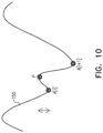
- Fig. 10 is a graph 150 illustrating merging of candidate annotations, and how rejection criteria are used, according to an embodiment of the present invention.
- the graph shows a unipolar derivative signal and two possible annotations (circles, marked A[i] and A[i+1]).
- pair elimination block 38 The purpose of pair elimination block 38 is to decide whether the upsloping amplitude change (marked with a vertical double-headed arrow) between the smallest derivative amplitude and the peak P between the two possible annotations is significant or not. If the change is considered significant both annotations are maintained, otherwise the weaker activation - A[i] is discarded.
- the candidate annotations that passed the earlier phases are revaluated in this block using additional features and metrics. Only annotations that pass this block and that also pass a user bipolar voltage controlled threshold are considered valid annotations. For each annotation multiple features are computed. Each feature value is given a fuzzy score ranging from zero to one, corresponding to a confidence value for the feature. Finally, all scores are combined together and their value is tested against a global score threshold. Those annotations that pass the global score threshold, i.e., that have a high confidence value, are considered valid annotations and those that do not, i.e., that have a low confidence value, are rejected.
- fuzzy functions described herein are examples of such functions that are used in one embodiment of the present invention. However, other such fuzzy functions or other probabilistic terms/functions will be apparent to those having ordinary skill in the art, and all such functions are assumed to be included within the scope of the present invention. In addition, for a specific requirement multiple fuzzy scores may be used (for example -fuzzy functions that highlight strong or small bipolar signals etc..)
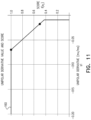
- Fig. 11 is a graph 160 of a unipolar derivative fuzzy function, according to an embodiment of the present invention.
- the graph provides a score f(s 1 ) assigned to the derivative, where the derivative value is herein termed s 1 .
- values of the derivative below -0.07 receive a score of 1, and values larger than -0.07 decrease linearly such that a 0.5 score is reached at a slope of - 0.018.
- Derivative values smaller than -0.01 receive a score of zero.
- the unipolar derivative s 1 is used in both detector stages, but unlike the first stage where it has a dichotomy threshold of 0.01 mv/ms, here its value is used to provide the score f(s 1 ). The higher the score the more probable that this is a valid annotation according to this feature alone.
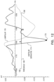
- Fig. 12 shows graphs illustrating unipolar signal segmentation, according to an embodiment of the present invention. The segmentation is described further below.
- a unipolar signal 170 and its derivative 174 are illustrated around a candidate annotation time index 176 (black dot).
- a dotted horizontal line 180 representing a threshold marks a search segment (typically approximately ⁇ 25 ms) in both directions. In one embodiment the segment value is defined as 20% of the absolute maximum unipolar derivative value at the annotation point.
- Segments A, B mark the time intervals within the search window where the signal derivative is below the threshold.
- a final segment in this example can be either segment A or, if certain conditions (described hereinbelow) are met, it can be the joint segment starting from onset of A to the end of B.
- a feature that we derive from the unipolar signal is the duration s 2 of the downslope segment around the candidate annotation.
- the aim is to detect the unipolar downslope from its initial descent until it starts to upslope.
- the motivation is to inspect features of the signals in that segment, such as properties of duration, amplitude, and their relationship, and to use them as a basis for a classifier.
- the inventors considered several methods for this task, all of which worked well for the obvious cases of a single slope, but the method described herein was selected since it works well on complicated cases having slope trend changes and local peaks within the slope segment.
- the segmentation is based on analyzing the unipolar derivative via the following steps:
- s 2 The duration determined from the above steps, herein termed s 2 , is then assigned a score f(s 2 ) using the fuzzy function described below with reference to Fig. 13 .
- Fig. 13 is a graph 190 of a unipolar duration fuzzy function, according to an embodiment of the present invention. Very short slopes of less than 2 ms are unlikely to originate from real activation; very long activations are probably far field events. In addition, the unipolar duration for local valid activation cannot be too short and cannot be too long. The above observations are encapsulated in the fuzzy function of Fig. 13 , which provides the score f(s 2 ).
- the function points 192, 194 are: ⁇ 2,0.5 ⁇ . ⁇ 19,0.5 ⁇ and the slopes are 0.5 and -0.5 respectively.
- Fig. 14 is a graph 200 of a unipolar amplitude fuzzy function, according to an embodiment of the present invention.
- the unipolar amplitude is the amplitude of the unipolar signal (herein termed s 3 ) in the detected activity segment (peak-to-peak) duration s 2 .
- the fuzzy function slope intersects points 202, 204: ⁇ 0.1,0.5 ⁇ , ⁇ 0.42,1 ⁇ .
- the score derived from the fuzzy function, f(s 3 ) is high the higher the amplitude of the signal. I.e., for high scores, and high amplitudes, the more likely it is that the signal originates from a local activation, unless the far field signals have a large amplitude.
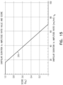
- Fig. 15 is a graph 210 of a unipolar duration to amplitude ratio fuzzy function, according to an embodiment of the present invention.
- the unipolar duration to amplitude ratio excludes high ratio values since the longer the activity and the smaller the amplitude, the more likely that this is a false annotation.
- Fig. 16 is a graph 220 of a bipolar amplitude fuzzy function, according to an embodiment of the present invention.
- the bipolar amplitude within the unipolar activity segment (peak-to-peak), s 2 is also used for scoring the likelihood of the candidate annotations. The higher the value, the more likely that this is a true activation.
- the amplitude is calculated on the baseline rejected bipolar smoothed signal after low pass of Gaussian and anti-aliasing filter.
- each feature receives a score and the scores are used together in generating a global score.
- the idea is that features can support one another in inclusion or exclusion of an annotation.
- the value of GS should pass a specific threshold, for example 0.8, for the annotation to be considered as valid.
- global scores can include substantially any combination of weighted average of individual scores, and/or dot products of individual scores.
- Such global scores can also include a composition of scores based on a subset of fuzzy features.
- a final stage of the algorithm is designed to provide the user the ability to eliminate annotations that were detected if they have a low bipolar amplitude.
- the required amplitude threshold is controlled by the user.
- the bipolar amplitude filtering compares the bipolar amplitude of each annotation that surpassed the post processing stage with a threshold. Only annotations having a bipolar amplitude that exceeds the threshold are passed to the system. (If a user desires to skip this stage she/he may set the threshold to zero, thus eliminating the rule of this stage.)
- the bipolar amplitude of each annotation is defined by measuring the peak-to-peak amplitude, baseline removed, 1KHz bipolar signal in a 14 ms window centered around the annotation time (maximum unipolar velocity point).
- a system default value of bipolar amplitude threshold is set to 30 micro Volts.
- This bipolar amplitude is different from the fuzzy controlled bipolar amplitude (described above), since this bipolar amplitude is determined on a fixed interval.
- the fuzzy classifier uses a dynamic segment of the unipolar activation and therefore in some embodiments the dynamic segment may be more meaningful as a classifier. In addition this classifier is used as a dichotomic user controlled threshold.
- trace files may be provided, to include
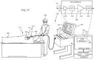
- Fig. 17 is a schematic illustration of an invasive medical procedure using an apparatus 400, according to an embodiment of the present invention.
- the procedure is performed by a medical professional 402, and, by way of example, the procedure in the description hereinbelow is assumed to comprise acquisition of ECG signals from a heart 404 of a human patient 406.
- professional 402 inserts a probe 408 into a sheath 410 that has been pre-positioned in a lumen of the patient.
- Sheath 410 is positioned so that a distal end 412 of the probe may enter the heart of the patient, after exiting a distal end 414 of the sheath, and contact tissue of the heart.
- Probe 408 may comprise any type of catheter that can be inserted into the heart of the patient, and that can be tracked, typically using a magnetic tracking system and/or an impedance measuring system.
- probe 408 may comprise a lasso catheter, a shaft-like catheter, or a pentaRay catheter, produced by Biosense Webster of Diamond Bar, CA, or catheters generally similar to these catheters. Biosense Webster also produces a magnetic tracking system and an impedance measuring system that may be used in embodiments of the present invention.
- Probe 408 comprises at least two electrodes 411, which are used to acquire the ECG signals used by processor 20 in performing the algorithms described herein.
- Apparatus 400 is controlled by processor 20 ( Fig. 1 ), and the processor may comprise real-time noise reduction circuitry 420, typically configured as a field programmable gate array (FPGA), followed by an analog-to-digital (A/D) signal conversion integrated circuit 424.
- the processor can pass the signal from A/D circuit 424 to another processor and can be programmed to perform the algorithms disclosed herein.
- Processor 20 is located in an operating console 430 of the apparatus.
- Console 430 comprises controls 432 which are used by professional 402 to communicate with the processor.
- processor 20 communicates with an ECG module 436 in a module bank 440, in order to acquire ECG signals as well as to perform the algorithms disclosed herein.
- ECG module 436 receives ECG signals from electrode 411. In one embodiment the signals are transferred, in module 436, through a low noise pre-amplifier 438, and via a band pass filter 440, to a main amplifier 442. Module 436 also comprises an analog to digital converter (ADC) 444, which transfers digitized values of the ECG signals to processor 20, for implementation by the processor of the algorithms described herein. Typically, processor 20 controls the operation of pre-amplifier 438, filter 440, amplifier 442, and ADC 444.
- ADC analog to digital converter
- ECG module 436 enables processor 20 to acquire and analyze EP (electrophysiological) signals received by electrode 411, including the ECG signals referred to herein.
- the signals are typically presented to professional 402 as voltage-time graphs, which are updated in real time, on a display screen 450.
- the software for processor 20 and module bank 440 may be downloaded to the processor in electronic form, over a network, for example.
- the software may be provided on non-transitory tangible media, such as optical, magnetic, or electronic storage media.
- module bank 50 typically comprises modules other than the ECG module described above, such as one or more tracking modules allowing the processor to track the distal end of probe 408.
- modules other modules are not illustrated in Fig. 1 . All modules may comprise hardware as well as software elements.
- results 452 of the algorithms described herein may also be presented to the algorithm user on the display screen.
Landscapes
- Health & Medical Sciences (AREA)
- Life Sciences & Earth Sciences (AREA)
- Engineering & Computer Science (AREA)
- Animal Behavior & Ethology (AREA)
- Public Health (AREA)
- Pathology (AREA)
- Physics & Mathematics (AREA)
- Biomedical Technology (AREA)
- Heart & Thoracic Surgery (AREA)
- Medical Informatics (AREA)
- Molecular Biology (AREA)
- Surgery (AREA)
- Veterinary Medicine (AREA)
- General Health & Medical Sciences (AREA)
- Biophysics (AREA)
- Cardiology (AREA)
- Physiology (AREA)
- Signal Processing (AREA)
- Artificial Intelligence (AREA)
- Computer Vision & Pattern Recognition (AREA)
- Psychiatry (AREA)
- Nuclear Medicine, Radiotherapy & Molecular Imaging (AREA)
- Radiology & Medical Imaging (AREA)
- Power Engineering (AREA)
- Measurement And Recording Of Electrical Phenomena And Electrical Characteristics Of The Living Body (AREA)
Claims (13)
- Computerimplementiertes Verfahren zum Identifizieren der Aktivierungszeitpunkte des Myokards, umfassend:Empfangen eines bipolaren Signals von einem Paar von Elektroden in der Nähe eines Myokards eines menschlichen Subjekts;Empfangen eines unipolaren Signals von einer ausgewählten des Paares von Elektroden;Vorverarbeiten des bipolaren Signals und des unipolaren Signals, wobei das Vorverarbeiten das Entfernen der Basislinienwanderung, das Anwenden eines Tiefpassfilters und eine Differenzierung umfasst;Extrahieren von Merkmalen für jede einer Vielzahl von Kandidatenannotationen, wobei die extrahierten Merkmale eine Zeitdauer eines Abfallsegments des unipolaren Signals umfassen;Verwerfen von Kandidatenannotationen basierend auf einer Teilmenge der extrahierten Merkmale;Verwerfen einer Kandidatenannotation aus allen Paaren von Kandidatenannotationen, die aus einer einzelnen Aktivierung herrühren;Berechnen einer Punktzahl für jede Kandidatenannotation basierend auf den extrahierten Merkmalen, wobei das Berechnen der Punktzahl das Berechnen der Punktzahl basierend auf der Zeitdauer des Abfallsegments des unipolaren Signals umfasst; undIdentifizieren von Kandidatenannotationen, deren Punktzahl über einem Punktzahlschwellenwert liegt, als Aktivierungszeitpunkte des Myokards.
- Verfahren nach Anspruch 1, wobei die extrahierten Merkmale eine Amplitude eines unipolaren Signalsegments innerhalb der Zeitdauer umfassen und das Berechnen der Punktzahl das Berechnen der Punktzahl basierend auf der Amplitude des unipolaren Signalsegments innerhalb der Zeitdauer umfasst.
- Verfahren nach Anspruch 2, wobei die extrahierten Merkmale ein Verhältnis zwischen der Amplitude und der Zeitdauer umfassen und das Berechnen der Punktzahl das Berechnen der Punktzahl basierend auf dem Verhältnis zwischen der Amplitude und der Zeitdauer umfasst.
- Verfahren nach Anspruch 2 oder Anspruch 3, wobei die extrahierten Merkmale eine Amplitude der bipolaren Ableitung innerhalb der Zeitdauer umfassen und das Berechnen der Punktzahl das Berechnen der Punktzahl basierend auf der Amplitude der bipolaren Ableitung innerhalb der Zeitdauer umfasst.
- Verfahren nach Anspruch 1, ferner umfassend:Berechnen (90) einer lokalen unipolaren minimalen Ableitung (118, 122) des unipolaren Signals (110) und eines Zeitpunkts des Auftretens der unipolaren minimalen Ableitung;Berechnen (94) einer bipolaren Ableitung des bipolaren Signals;Auswerten (96) eines Verhältnisses der bipolaren Ableitung zur lokalen unipolaren minimalen Ableitung; undwenn das Verhältnis größer als ein voreingestellter Schwellenverhältniswert ist, Identifizieren des Zeitpunkts des Auftretens als Zeitpunkt der Aktivierung des Myokards.
- Einrichtung (400), umfassend:ein Paar von Elektroden (411), das konfiguriert ist, um in der Nähe eines Myokards eines menschlichen Subjekts platziert zu werden; undeinen Prozessor (20), der konfiguriert ist zum:Empfangen eines bipolaren Signals (104) vom Paar von Elektroden,Empfangen eines unipolaren Signals (100, 110) von einer ausgewählten des Paares von Elektroden;Vorverarbeiten des bipolaren Signals und des unipolaren Signals, wobei das Vorverarbeiten das Entfernen der Basislinienwanderung, das Anwenden eines Tiefpassfilters und Differenzieren umfasst;Extrahieren von Merkmalen für jede einer Vielzahl von Kandidatenannotationen, wobei die extrahierten Merkmale eine Zeitdauer eines Abfallsegments des unipolaren Signals umfassen;Verwerfen von Kandidatenannotationen basierend auf einer Teilmenge der extrahierten Merkmale;Verwerfen einer Kandidatenannotation aus allen Paaren von Kandidatenannotationen, die aus einem gleichen Aktivierungszeitpunkt herrühren;Berechnen einer Punktzahl für jede Kandidatenannotation basierend auf den extrahierten Merkmalen, wobei das Berechnen der Punktzahl das Berechnen der Punktzahl basierend auf der Zeitdauer des Abfallsegments des unipolaren Signals umfasst; undIdentifizieren von Kandidatenannotationen, deren Punktzahl über einem Punktzahlschwellenwert liegt, als Aktivierungszeitpunkte des Myokards.
- Einrichtung nach Anspruch 6, wobei die extrahierten Merkmale eine Amplitude eines unipolaren Signalsegments innerhalb der Zeitdauer umfassen und das Berechnen der Punktzahl das Berechnen der Punktzahl basierend auf der Amplitude des unipolaren Signalsegments innerhalb der Zeitdauer umfasst.
- Einrichtung nach Anspruch 7, wobei die extrahierten Merkmale ein Verhältnis zwischen der Amplitude und der Zeitdauer umfassen und das Berechnen der Punktzahl das Berechnen der Punktzahl basierend auf dem Verhältnis zwischen der Amplitude und der Zeitdauer umfasst.
- Einrichtung nach einem der Ansprüche 6 bis 8, wobei die extrahierten Merkmale eine Amplitude der bipolaren Ableitung innerhalb der Zeitdauer umfassen und das Berechnen der Punktzahl das Berechnen der Punktzahl basierend auf der Amplitude der bipolaren Ableitung innerhalb der Zeitdauer umfasst.
- Einrichtung nach Anspruch 6, wobei der Prozessor ferner konfiguriert ist zum:Berechnen einer lokalen unipolaren minimalen Ableitung (118, 122) des unipolaren Signals und eines Zeitpunkts des Auftretens der unipolaren minimalen Ableitung;Berechnen einer bipolaren Ableitung (106) des bipolaren Signals (104);Auswerten eines Verhältnisses der bipolaren Ableitung zur lokalen unipolaren minimalen Ableitung; undwenn das Verhältnis größer als ein voreingestellter Schwellenverhältniswert ist, Identifizieren des Zeitpunkts des Auftretens als Zeitpunkt der Aktivierung des Myokards.
- Verfahren nach Anspruch 5 oder Einrichtung nach Anspruch 10, und ferner umfassend, wenn die bipolare Ableitung kleiner als ein voreingestellter Schwellenwert für die bipolare Ableitung ist, Zuweisen des Zeitpunkts des Auftretens als Zeitpunkt der Aktivierung des Myokards.
- Verfahren nach Anspruch 5 oder Einrichtung nach Anspruch 10, und ferner umfassend, wenn die lokale unipolare minimale Ableitung kleiner als ein voreingestellter Schwellenwert für die unipolare Ableitung ist, Zuweisen des Zeitpunkts des Auftretens als Zeitpunkt der Aktivierung des Myokards.
- Verfahren nach Anspruch 5 oder Einrichtung nach Anspruch 10, und umfassend nur das Zuweisen des Zeitpunkts des Auftretens als Zeitpunkt der Aktivierung des Myokards, wenn eine Amplitude des bipolaren Signals größer ist als ein voreingestellter Schwellenwert des bipolaren Signals.
Applications Claiming Priority (3)
| Application Number | Priority Date | Filing Date | Title |
|---|---|---|---|
| US201662373458P | 2016-08-11 | 2016-08-11 | |
| US15/646,373 US10383534B2 (en) | 2016-08-11 | 2017-07-11 | Annotation of a wavefront |
| EP17185784.0A EP3281581B1 (de) | 2016-08-11 | 2017-08-10 | Annotation einer wellenfront |
Related Parent Applications (1)
| Application Number | Title | Priority Date | Filing Date |
|---|---|---|---|
| EP17185784.0A Division EP3281581B1 (de) | 2016-08-11 | 2017-08-10 | Annotation einer wellenfront |
Publications (3)
| Publication Number | Publication Date |
|---|---|
| EP4042933A1 EP4042933A1 (de) | 2022-08-17 |
| EP4042933C0 EP4042933C0 (de) | 2025-06-04 |
| EP4042933B1 true EP4042933B1 (de) | 2025-06-04 |
Family
ID=59649504
Family Applications (2)
| Application Number | Title | Priority Date | Filing Date |
|---|---|---|---|
| EP22162146.9A Active EP4042933B1 (de) | 2016-08-11 | 2017-08-10 | Annotation einer wellenfront |
| EP17185784.0A Active EP3281581B1 (de) | 2016-08-11 | 2017-08-10 | Annotation einer wellenfront |
Family Applications After (1)
| Application Number | Title | Priority Date | Filing Date |
|---|---|---|---|
| EP17185784.0A Active EP3281581B1 (de) | 2016-08-11 | 2017-08-10 | Annotation einer wellenfront |
Country Status (7)
| Country | Link |
|---|---|
| US (4) | US10383534B2 (de) |
| EP (2) | EP4042933B1 (de) |
| JP (1) | JP7002881B2 (de) |
| CN (1) | CN107714031B (de) |
| AU (1) | AU2017208228A1 (de) |
| CA (1) | CA2975181A1 (de) |
| IL (2) | IL253755B (de) |
Families Citing this family (12)
| Publication number | Priority date | Publication date | Assignee | Title |
|---|---|---|---|---|
| US10383534B2 (en) * | 2016-08-11 | 2019-08-20 | Biosense Webster (Israel) Ltd. | Annotation of a wavefront |
| CN112004463B (zh) * | 2018-04-26 | 2024-03-22 | 圣犹达医疗用品心脏病学部门有限公司 | 用于标测心律失常驱动器位点的系统和方法 |
| US11160481B2 (en) | 2018-08-22 | 2021-11-02 | Biosense Webster (Israel) Ltd. | Atrial fibrillation mapping using atrial fibrillation cycle length (AFCL) gradients |
| US11452485B2 (en) | 2019-08-05 | 2022-09-27 | Biosense Webster (Israel) Ltd. | Electroanatomical map re-annotation |
| US11278233B2 (en) | 2019-11-15 | 2022-03-22 | Biosense Webster (Israel) Ltd. | Method and apparatus to find abnormal activations in intra-cardiac electrocardiograms based on specificity and sensitivity |
| US11311226B2 (en) * | 2019-12-12 | 2022-04-26 | Biosense Webster (Israel) Ltd. | Detection of ventricular activity using unipolar and bipolar signals |
| US12239449B2 (en) | 2020-06-10 | 2025-03-04 | Biosense Webster (Israel) Ltd. | System and method to detect stable arrhythmia heartbeat and to calculate and detect cardiac mapping annotations |
| US20210393187A1 (en) * | 2020-06-19 | 2021-12-23 | Biosense Webster (Israel) Ltd. | Ventricular far field estimation using autoencoder |
| US11748616B2 (en) * | 2020-08-12 | 2023-09-05 | Biosense Webster (Israel) Ltd. | Detection of activation in electrograms using neural-network-trained preprocessing of intracardiac electrograms |
| WO2023089494A1 (en) | 2021-11-22 | 2023-05-25 | Biosense Webster (Israel) Ltd. | Algorithm for optimal beat selection |
| US11969255B2 (en) | 2021-12-12 | 2024-04-30 | Biosense Webster (Israel) Ltd. | Detection of fractionated signals in stable arrhythmias |
| US12336832B2 (en) * | 2022-03-11 | 2025-06-24 | Biosense Webster (Israel) Ltd. | P-wave detection using intracardiac electrodes |
Family Cites Families (18)
| Publication number | Priority date | Publication date | Assignee | Title |
|---|---|---|---|---|
| CA2942986A1 (en) * | 2008-10-09 | 2010-04-15 | The Regents Of The University Of California | Methods, system and apparatus for the detection, diagnosis and treatment of biological rhythm disorders |
| US8050750B2 (en) | 2009-01-27 | 2011-11-01 | Medtronic, Inc. | Event discrimination using unipolar and bipolar signal differences |
| US9398862B2 (en) * | 2009-04-23 | 2016-07-26 | Rhythmia Medical, Inc. | Multi-electrode mapping system |
| CA2795767C (en) * | 2010-04-08 | 2018-08-21 | Topera, Inc. | Methods, system and apparatus for the detection, diagnosis and treatment of biological rhythm disorders |
| US9277872B2 (en) * | 2011-01-13 | 2016-03-08 | Rhythmia Medical, Inc. | Electroanatomical mapping |
| US8165666B1 (en) | 2011-05-02 | 2012-04-24 | Topera, Inc. | System and method for reconstructing cardiac activation information |
| US9050006B2 (en) | 2011-05-02 | 2015-06-09 | The Regents Of The University Of California | System and method for reconstructing cardiac activation information |
| EP2526861A1 (de) | 2011-05-23 | 2012-11-28 | Maastricht University | Nichtinvasive Klassifizierung von Vorhofflimmern durch probabilistische Intervallanalyse von einem transösophagealen Elektrokardiogramm |
| US9002455B2 (en) * | 2012-01-17 | 2015-04-07 | Pacesetter, Inc. | Systems and methods for assessing and exploiting concurrent cathodal and anodal capture using an implantable medical device |
| US9833157B2 (en) * | 2012-04-23 | 2017-12-05 | Biosense Webster (Israel) Ltd. | Cardiac activation time detection |
| CA2903109A1 (en) * | 2013-03-15 | 2014-09-18 | The Regents Of The University Of California | System and method for reconstructing cardiac activation information |
| US9615760B2 (en) * | 2013-06-17 | 2017-04-11 | Biosense Webster (Israel), Ltd. | Multiple bipolar sampling |
| US9132274B2 (en) | 2013-07-26 | 2015-09-15 | Medtronic, Inc. | Determining onsets and offsets of cardiac depolarization and repolarization waves |
| US9380953B2 (en) * | 2014-01-29 | 2016-07-05 | Biosense Webster (Israel) Ltd. | Hybrid bipolar/unipolar detection of activation wavefront |
| US10980439B2 (en) * | 2014-08-06 | 2021-04-20 | Biosense Webster (Israel) Ltd | Wavefront analysis based on ablation parameters |
| US9421061B2 (en) * | 2014-12-18 | 2016-08-23 | Biosense Webster (Israel) Ltd. | Ventricular far field reduction |
| US9610045B2 (en) * | 2015-07-31 | 2017-04-04 | Medtronic, Inc. | Detection of valid signals versus artifacts in a multichannel mapping system |
| US10383534B2 (en) * | 2016-08-11 | 2019-08-20 | Biosense Webster (Israel) Ltd. | Annotation of a wavefront |
-
2017
- 2017-07-11 US US15/646,373 patent/US10383534B2/en active Active
- 2017-07-25 AU AU2017208228A patent/AU2017208228A1/en not_active Abandoned
- 2017-07-31 IL IL253755A patent/IL253755B/en active IP Right Grant
- 2017-08-02 CA CA2975181A patent/CA2975181A1/en not_active Abandoned
- 2017-08-10 EP EP22162146.9A patent/EP4042933B1/de active Active
- 2017-08-10 JP JP2017155070A patent/JP7002881B2/ja active Active
- 2017-08-10 EP EP17185784.0A patent/EP3281581B1/de active Active
- 2017-08-11 CN CN201710686453.8A patent/CN107714031B/zh active Active
-
2019
- 2019-07-17 US US16/514,091 patent/US11071489B2/en active Active
-
2020
- 2020-10-12 IL IL277987A patent/IL277987B/en unknown
-
2021
- 2021-06-18 US US17/351,357 patent/US12036029B2/en active Active
-
2024
- 2024-06-20 US US18/748,988 patent/US20240335155A1/en active Pending
Also Published As
| Publication number | Publication date |
|---|---|
| US20180042504A1 (en) | 2018-02-15 |
| CA2975181A1 (en) | 2018-02-11 |
| EP3281581A1 (de) | 2018-02-14 |
| EP4042933A1 (de) | 2022-08-17 |
| IL253755A0 (en) | 2017-09-28 |
| EP3281581B1 (de) | 2022-03-16 |
| JP2018023787A (ja) | 2018-02-15 |
| CN107714031A (zh) | 2018-02-23 |
| JP7002881B2 (ja) | 2022-01-20 |
| US11071489B2 (en) | 2021-07-27 |
| US20240335155A1 (en) | 2024-10-10 |
| US10383534B2 (en) | 2019-08-20 |
| EP4042933C0 (de) | 2025-06-04 |
| IL253755B (en) | 2020-10-29 |
| IL277987B (en) | 2022-03-01 |
| US12036029B2 (en) | 2024-07-16 |
| IL277987A (en) | 2020-11-30 |
| US20210307667A1 (en) | 2021-10-07 |
| AU2017208228A1 (en) | 2018-03-01 |
| CN107714031B (zh) | 2021-12-24 |
| US20190336027A1 (en) | 2019-11-07 |
Similar Documents
| Publication | Publication Date | Title |
|---|---|---|
| US12036029B2 (en) | Annotation of an electrocardiogramic wavefront | |
| US11690556B2 (en) | Classifying ECG signals | |
| EP2901923B1 (de) | Hybride bipolare/unipolare Detektion einer Aktivierungswellenfront | |
| AU2012247057B2 (en) | Accurate time annotation of intracardiac ecg signals | |
| JP2015139706A5 (de) | ||
| Kotas et al. | Towards noise immune detection of fetal QRS complexes | |
| US9901277B2 (en) | Cycle length iteration for the detection of atrial activations from electrogram recordings of atrial fibrillation | |
| EP3831304A1 (de) | Intrakardialer musterabgleich | |
| US20190374123A1 (en) | Predicting atrial fibrillation or stroke using p-wave analysis | |
| WO2020242334A1 (en) | System and method of automated electrocardiogram analysis and interpretation | |
| US20130267860A1 (en) | Seed-beat selection method for signal-averaged electrocardiography |
Legal Events
| Date | Code | Title | Description |
|---|---|---|---|
| PUAI | Public reference made under article 153(3) epc to a published international application that has entered the european phase |
Free format text: ORIGINAL CODE: 0009012 |
|
| STAA | Information on the status of an ep patent application or granted ep patent |
Free format text: STATUS: THE APPLICATION HAS BEEN PUBLISHED |
|
| AC | Divisional application: reference to earlier application |
Ref document number: 3281581 Country of ref document: EP Kind code of ref document: P |
|
| AK | Designated contracting states |
Kind code of ref document: A1 Designated state(s): AL AT BE BG CH CY CZ DE DK EE ES FI FR GB GR HR HU IE IS IT LI LT LU LV MC MK MT NL NO PL PT RO RS SE SI SK SM TR |
|
| STAA | Information on the status of an ep patent application or granted ep patent |
Free format text: STATUS: REQUEST FOR EXAMINATION WAS MADE |
|
| 17P | Request for examination filed |
Effective date: 20230217 |
|
| RBV | Designated contracting states (corrected) |
Designated state(s): AL AT BE BG CH CY CZ DE DK EE ES FI FR GB GR HR HU IE IS IT LI LT LU LV MC MK MT NL NO PL PT RO RS SE SI SK SM TR |
|
| GRAP | Despatch of communication of intention to grant a patent |
Free format text: ORIGINAL CODE: EPIDOSNIGR1 |
|
| STAA | Information on the status of an ep patent application or granted ep patent |
Free format text: STATUS: GRANT OF PATENT IS INTENDED |
|
| INTG | Intention to grant announced |
Effective date: 20250212 |
|
| GRAS | Grant fee paid |
Free format text: ORIGINAL CODE: EPIDOSNIGR3 |
|
| GRAA | (expected) grant |
Free format text: ORIGINAL CODE: 0009210 |
|
| STAA | Information on the status of an ep patent application or granted ep patent |
Free format text: STATUS: THE PATENT HAS BEEN GRANTED |
|
| AC | Divisional application: reference to earlier application |
Ref document number: 3281581 Country of ref document: EP Kind code of ref document: P |
|
| AK | Designated contracting states |
Kind code of ref document: B1 Designated state(s): AL AT BE BG CH CY CZ DE DK EE ES FI FR GB GR HR HU IE IS IT LI LT LU LV MC MK MT NL NO PL PT RO RS SE SI SK SM TR |
|
| REG | Reference to a national code |
Ref country code: GB Ref legal event code: FG4D |
|
| REG | Reference to a national code |
Ref country code: CH Ref legal event code: EP |
|
| REG | Reference to a national code |
Ref country code: DE Ref legal event code: R096 Ref document number: 602017089863 Country of ref document: DE |
|
| REG | Reference to a national code |
Ref country code: IE Ref legal event code: FG4D |
|
| U01 | Request for unitary effect filed |
Effective date: 20250623 |
|
| U07 | Unitary effect registered |
Designated state(s): AT BE BG DE DK EE FI FR IT LT LU LV MT NL PT RO SE SI Effective date: 20250701 |
|
| U20 | Renewal fee for the european patent with unitary effect paid |
Year of fee payment: 9 Effective date: 20250709 |
|
| PG25 | Lapsed in a contracting state [announced via postgrant information from national office to epo] |
Ref country code: ES Free format text: LAPSE BECAUSE OF FAILURE TO SUBMIT A TRANSLATION OF THE DESCRIPTION OR TO PAY THE FEE WITHIN THE PRESCRIBED TIME-LIMIT Effective date: 20250604 |
|
| PG25 | Lapsed in a contracting state [announced via postgrant information from national office to epo] |
Ref country code: GR Free format text: LAPSE BECAUSE OF FAILURE TO SUBMIT A TRANSLATION OF THE DESCRIPTION OR TO PAY THE FEE WITHIN THE PRESCRIBED TIME-LIMIT Effective date: 20250905 Ref country code: NO Free format text: LAPSE BECAUSE OF FAILURE TO SUBMIT A TRANSLATION OF THE DESCRIPTION OR TO PAY THE FEE WITHIN THE PRESCRIBED TIME-LIMIT Effective date: 20250904 |
|
| PG25 | Lapsed in a contracting state [announced via postgrant information from national office to epo] |
Ref country code: PL Free format text: LAPSE BECAUSE OF FAILURE TO SUBMIT A TRANSLATION OF THE DESCRIPTION OR TO PAY THE FEE WITHIN THE PRESCRIBED TIME-LIMIT Effective date: 20250604 |
|
| PGFP | Annual fee paid to national office [announced via postgrant information from national office to epo] |
Ref country code: GB Payment date: 20250703 Year of fee payment: 9 |
|
| PG25 | Lapsed in a contracting state [announced via postgrant information from national office to epo] |
Ref country code: HR Free format text: LAPSE BECAUSE OF FAILURE TO SUBMIT A TRANSLATION OF THE DESCRIPTION OR TO PAY THE FEE WITHIN THE PRESCRIBED TIME-LIMIT Effective date: 20250604 |
|
| PG25 | Lapsed in a contracting state [announced via postgrant information from national office to epo] |
Ref country code: RS Free format text: LAPSE BECAUSE OF FAILURE TO SUBMIT A TRANSLATION OF THE DESCRIPTION OR TO PAY THE FEE WITHIN THE PRESCRIBED TIME-LIMIT Effective date: 20250904 |