EP4042915B1 - Modular hand-held kitchen appliance - Google Patents
Modular hand-held kitchen appliance Download PDFInfo
- Publication number
- EP4042915B1 EP4042915B1 EP22153817.6A EP22153817A EP4042915B1 EP 4042915 B1 EP4042915 B1 EP 4042915B1 EP 22153817 A EP22153817 A EP 22153817A EP 4042915 B1 EP4042915 B1 EP 4042915B1
- Authority
- EP
- European Patent Office
- Prior art keywords
- blade
- housing
- cup
- blade assembly
- power coupling
- Prior art date
- Legal status (The legal status is an assumption and is not a legal conclusion. Google has not performed a legal analysis and makes no representation as to the accuracy of the status listed.)
- Active
Links
Images




Classifications
-
- A—HUMAN NECESSITIES
- A47—FURNITURE; DOMESTIC ARTICLES OR APPLIANCES; COFFEE MILLS; SPICE MILLS; SUCTION CLEANERS IN GENERAL
- A47J—KITCHEN EQUIPMENT; COFFEE MILLS; SPICE MILLS; APPARATUS FOR MAKING BEVERAGES
- A47J43/00—Implements for preparing or holding food, not provided for in other groups of this subclass
- A47J43/04—Machines for domestic use not covered elsewhere, e.g. for grinding, mixing, stirring, kneading, emulsifying, whipping or beating foodstuffs, e.g. power-driven
- A47J43/07—Parts or details, e.g. mixing tools, whipping tools
- A47J43/075—Safety devices
- A47J43/0761—Safety devices for machines with tools driven from the lower side
- A47J43/0766—Safety devices for machines with tools driven from the lower side activated by the proper positioning of the mixing bowl
-
- A—HUMAN NECESSITIES
- A47—FURNITURE; DOMESTIC ARTICLES OR APPLIANCES; COFFEE MILLS; SPICE MILLS; SUCTION CLEANERS IN GENERAL
- A47J—KITCHEN EQUIPMENT; COFFEE MILLS; SPICE MILLS; APPARATUS FOR MAKING BEVERAGES
- A47J42/00—Coffee mills; Spice mills
- A47J42/38—Parts or details
- A47J42/56—Safety devices
-
- A—HUMAN NECESSITIES
- A47—FURNITURE; DOMESTIC ARTICLES OR APPLIANCES; COFFEE MILLS; SPICE MILLS; SUCTION CLEANERS IN GENERAL
- A47J—KITCHEN EQUIPMENT; COFFEE MILLS; SPICE MILLS; APPARATUS FOR MAKING BEVERAGES
- A47J42/00—Coffee mills; Spice mills
- A47J42/22—Coffee mills; Spice mills having pulverising beaters or rotary knives
- A47J42/26—Coffee mills; Spice mills having pulverising beaters or rotary knives mechanically driven
-
- A—HUMAN NECESSITIES
- A47—FURNITURE; DOMESTIC ARTICLES OR APPLIANCES; COFFEE MILLS; SPICE MILLS; SUCTION CLEANERS IN GENERAL
- A47J—KITCHEN EQUIPMENT; COFFEE MILLS; SPICE MILLS; APPARATUS FOR MAKING BEVERAGES
- A47J42/00—Coffee mills; Spice mills
- A47J42/22—Coffee mills; Spice mills having pulverising beaters or rotary knives
- A47J42/28—Beaters or knives
-
- A—HUMAN NECESSITIES
- A47—FURNITURE; DOMESTIC ARTICLES OR APPLIANCES; COFFEE MILLS; SPICE MILLS; SUCTION CLEANERS IN GENERAL
- A47J—KITCHEN EQUIPMENT; COFFEE MILLS; SPICE MILLS; APPARATUS FOR MAKING BEVERAGES
- A47J43/00—Implements for preparing or holding food, not provided for in other groups of this subclass
- A47J43/04—Machines for domestic use not covered elsewhere, e.g. for grinding, mixing, stirring, kneading, emulsifying, whipping or beating foodstuffs, e.g. power-driven
- A47J43/044—Machines for domestic use not covered elsewhere, e.g. for grinding, mixing, stirring, kneading, emulsifying, whipping or beating foodstuffs, e.g. power-driven with tools driven from the top side
- A47J2043/04409—Apparatus of hand held type
- A47J2043/04427—Apparatus of hand held type with housing extending vertically in line with the tool axis
Definitions
- the invention relates to kitchen appliances having a single powerhead capable of being attached to a variety of kitchen appliance attachments.
- Modular hand-held kitchen appliances are known in the art. These products typically include a universal powerhead that can be used with different attachments.
- the powerhead and exemplary attachments such as a grinder and wine opener, are described in application no. 17/167,150, from which this application claims priority.
- additional attachments the benefit of the system becomes more compelling by providing an alternative to buying multiple bulky and expensive appliances.
- the document GB 2414381 discloses a modular kitchen appliance.
- a modular kitchen appliance of the present invention aims to provide a powered solution for a wide variety of kitchen tasks. These attachments can go beyond mixing and blending and extend to other areas of the kitchen where a powered solution would be beneficial.
- a modular kitchen appliance comprising the features of claim 1.
- a can opener attachment is disclosed that is capable of use with the powerhead.
- the can opener is a side cutting unit that slices through the side of the can just underneath the lip of the lid. This type of can opener provides a smoother cut, reducing the jagged edges often found in top cutting can openers.
- Fig. 1 shows a modular kitchen appliance of the present invention having a universal powerhead 10 and a coffee grinder attachment 20.
- the grinder 10 is described as a coffee grinder, it should be understood that any beans, nuts, spices or other materials may be ground by the present invention.
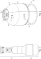
- Fig. 2 shows the grinder attachment 20 having a housing 22 and a cup 24.
- the housing 22 is made up of two clamshell portions 26 that are held together by screws 28.
- the top of the housing forms an opening 30 including ribs 32 for connection to the powerhead.
- the grinder attachment 20 is attached to the powerhead 10 as described in appl. no. 17/167,150.
- Fig. 3 shows the coffee grinder with one of the clamshells 26 removed to show the internal components
- Fig. 4 is an exploded view of the components.
- the grinder consists of two assemblies, a blade assembly 80 and a power transmission assembly 90.
- the power transmission assembly 90 delivers power from the powerhead 10 to the blade 48 and includes a power coupling 46 that connects to an output or drive shaft in the power head 10.
- a bearing 42 is secured in a groove 27 (see Fig. 3 ) in clamshell housing 26 and holds the power coupling 46.
- a plate 38 is slidable along the power coupling 46, with a spring 54 (not shown in Fig. 3 ) held between the plate 38 and housing 22.
- the blade assembly 80 comprises a transmission axle 47 that detachably connects to the power coupling 46.
- the transmission axle 47 is secured by bearing 43 which is pressed fit into blade cover 34.
- a blade 48 is fixedly connected to the transmission axle 47.
- An optional liner 36 is placed on the inside of the blade cover 34, and can be included to help protect the blade cover 34 from wear during grinding.
- the liner 36 is made of a metal material, while the cover 34 is made of a plastic material.
- the blade cover 34 includes a circular perimeter wall 33 that encloses the blade 48 and includes a shelf 35 that extends out from the wall 33.
- a gasket 52 is placed in the corner of the wall 33 and shelf 35 to provide a seal when attached to cup 24.
- the cup 24 is filled with beans or other material and is slidingly slipped onto the blade cover 34.
- the cup 24 is shown friction fit onto the blade cover's wall 33, but other attachments method between the cup and blade cover are envisioned within the scope of the invention.
- An example of an alternate attachment method is a simple twist and lock feature.
- the cup 24 With the cup 24 attached to the blade cover 34 (and consequently, the blade assembly 80), it can be screwed onto the housing 22.
- the cup includes a top rim portion 25 whose exterior is threaded, and the threads correspond with threads on an interior surface of the housing 22.
- the blade assembly 80 is secured on top of the cup 24 as the combined cup 24 and blade assembly 80 are screwed onto the housing 22.
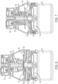
- the blade cover 34 moves upward within the housing 22, it pushes against plate 38, which is biased by spring 54, until the transmission axle 47 engages with the power coupling 46. Power can now be delivered to the blade 48, and the grinder is now operational as shown in Fig. 7 .
- the powerhead 10 can now be turned on and the grinder 20 turned upside down so that any material in the cup 24 will be cut by the rotating blade 48.
- the process is reversed and the grinder 20 is flipped right side up, and the cup 24 and blade assembly 80 are unscrewed from the housing 22.
- the spring 54 pushes the plate 38 downward until it's stopped by a ledge 56.
- the ledge 56 retains the plate 38 in the housing 22.
- An important function of the plate 38 is to help separate the transmission axle 47 from power coupling 46. In this way, power cannot be transferred to the blade 48 except when the cup 24 is screwed into the housing 22. With the cup 24 unscrewed from the housing 22, the blade assembly 80 can be separated from the cup 24, without any risk of the blade 48 being turned on.
- Fig. 8 shows yet another example, not covered by the claim, of a kitchen appliance attachment, in this case a can opener 100, that can be attached to the powerhead 10.
- a can 102 is shown attached to the can opener 100.
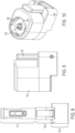
- Fig. 9 is a side view of the can opener 100, which is comprised of a main housing 110 and a lever 104.
- Fig. 10 is a top view of the can opener 100 which shows an opening 105 through which a power coupling 106 extends.
- the power coupling 106 is releasably attached to a drive shaft of the powerhead 10, which powers the operation of the can opener 100.
- the opening further includes ribs 108 along its interior edge for securing it to the powerhead 10 as explained in related application no. 17/167,150.
- FIG. 11 an exploded view of the can opener 100 is shown.
- the main housing 110 formed from two clamshell portions 110a and 110b.
- a transmission axle 112 is located in the housing and includes the power coupling 106, a reduction gearbox 114 and an output shaft 116.
- the output shaft 116 is fixedly connected to feed wheel 118 by a pin (not shown).
- the reduction gearbox 114 reduces the rotational speed of the drive shaft from the powerhead 10 to a much lower speed for spinning the can as it's being cut.
- the housing 110 further encloses a blade assembly 120 that includes a shuttle 122, a blade 124 and a roller 126.
- a bolt and washer 128 secure the blade 124 and roller 126 to the shuttle 122.
- Fig. 12 shows the assembled blade assembly 120.
- Figs. 13-14 are sectional views of the blade assembly 120 within the housing 110 in the disengaged and engaged position, respectively.
- the shuttle 122 includes rails 130 that travel within a groove 132 formed in the housing (see Fig. 11 ).
- the shuttle includes an extension 134 that captures one end of a spring 136. The other end of the spring 136 abuts an internal wall 133 of the housing 110, and biases the shuttle 122 outwardly (e.g. to the right in Figs. 13 and 14 ).
- the blade 124 is shown disengaged from the can 102.
- the can 102 is placed against feed wheel 118 which engages a lip 103 of can 102.
- the lever 104 is then pulled down, pushing the shuttle 122 inward so that blade 124 punctures the side of the can 102.
- the lever 104 is fixed to the housing 110 by a pin 140 through an aperture 142. In the disengaged position, the shuttle 122 abuts a relatively flat side of the lever 104.
- Fig. 14 shows the lever 104 after it's been rotated 90 degrees into the engage position, where the end of the lever 104, which is generally oval shaped, pushes the shuttle 122 against the force of the spring 136.
- the lever is prevented from over-rotating by a ledge 144 in the housing 110 that acts as a stop.
- the lever 104 When the lever 104 is rotated, it pushes the shuttle 122 so that the blade 124 cuts through the side of the can 102.
- the lip 103 of the can 102 is pinched between the feed wheel 118 and the roller 126.
- the powerhead can then be turned on, which rotates the feed wheel 118 and cuts the can. See also Fig. 15 .
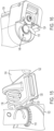
- a magnet 146 can be provided in the housing adjacent the feed wheel 118 (see Fig 16 ). The magnet 146 helps retain the can lid after the top of the can 102 has been cut off.
Landscapes
- Engineering & Computer Science (AREA)
- Mechanical Engineering (AREA)
- Food Science & Technology (AREA)
- Crushing And Pulverization Processes (AREA)
- Devices For Opening Bottles Or Cans (AREA)
Description
- The invention relates to kitchen appliances having a single powerhead capable of being attached to a variety of kitchen appliance attachments.
- This section provides background information related to the present disclosure which is not necessarily prior art.
- Modular hand-held kitchen appliances are known in the art. These products typically include a universal powerhead that can be used with different attachments. The powerhead and exemplary attachments, such as a grinder and wine opener, are described in application no. 17/167,150, from which this application claims priority. However, with additional attachments, the benefit of the system becomes more compelling by providing an alternative to buying multiple bulky and expensive appliances. The document
GB 2414381 - Therefore, a modular kitchen appliance of the present invention aims to provide a powered solution for a wide variety of kitchen tasks. These attachments can go beyond mixing and blending and extend to other areas of the kitchen where a powered solution would be beneficial.
- In accordance with one aspect, there is a modular kitchen appliance, comprising the features of claim 1.
- In another aspect not covered by the present claim, there is provided a can opener attachment is disclosed that is capable of use with the powerhead. The can opener is a side cutting unit that slices through the side of the can just underneath the lip of the lid. This type of can opener provides a smoother cut, reducing the jagged edges often found in top cutting can openers.
- Further areas of applicability will become apparent from the description provided herein. The description and specific examples in this application are intended for purposes of illustration only and are not intended to limit the scope of the present disclosure.
- Further features and advantages of the present invention will be better understood by reference to the following description, which is given by way of example and in association with the accompanying drawings, in which:
-
Fig. 1 shows a powerhead and grinder attachment; -
Fig. 2 is the grinder attachment ofFig. 1 ; -
Fig. 3 is a view ofFig. 2 , with a portion of the housing removed; -
Fig. 4 is an exploded view of the components of the grinder; -
Fig. 5 is a section view of the blade assembly; -
Fig. 6 is a section view of the grinder attachment disengaged from the powerhead; -
Fig. 7 is a section view of the grinder attachment engaged with the powerhead; -
Fig. 8 is the powerhead with a can opener attachment and a can; -
Fig. 9 is a side view of the can opener attachment; -
Fig. 10 is a top view of the can opener attachment; -
Fig. 11 is an exploded view of the can opener attachment; -
Fig. 12 is a blade assembly; -
Fig. 13 is a side section view of the can opener attachment in the disengaged position; -
Fig. 14 is a side section view of the can opener attachment in the engaged position; -
Fig. 15 shows the blade assembly during the cutting operation; and -
Fig. 16 is a bottom view of the can opener attachment. - Note that
figures 8-16 show embodiments not covered by the claims. -
Fig. 1 shows a modular kitchen appliance of the present invention having auniversal powerhead 10 and acoffee grinder attachment 20. Although thegrinder 10 is described as a coffee grinder, it should be understood that any beans, nuts, spices or other materials may be ground by the present invention. -
Fig. 2 shows thegrinder attachment 20 having ahousing 22 and acup 24. Thehousing 22 is made up of twoclamshell portions 26 that are held together byscrews 28. The top of the housing forms an opening 30 includingribs 32 for connection to the powerhead. Thegrinder attachment 20 is attached to thepowerhead 10 as described in appl. no. 17/167,150. -
Fig. 3 shows the coffee grinder with one of theclamshells 26 removed to show the internal components, andFig. 4 is an exploded view of the components. The grinder consists of two assemblies, ablade assembly 80 and apower transmission assembly 90. - The
power transmission assembly 90 will be described first. It delivers power from thepowerhead 10 to theblade 48 and includes apower coupling 46 that connects to an output or drive shaft in thepower head 10. Abearing 42 is secured in a groove 27 (seeFig. 3 ) inclamshell housing 26 and holds thepower coupling 46. Aplate 38 is slidable along thepower coupling 46, with a spring 54 (not shown inFig. 3 ) held between theplate 38 and housing 22. - Next is the
blade assembly 80, which is also shown inFig. 5 . The blade assembly comprises atransmission axle 47 that detachably connects to thepower coupling 46. Thetransmission axle 47 is secured by bearing 43 which is pressed fit intoblade cover 34. Ablade 48 is fixedly connected to thetransmission axle 47. Anoptional liner 36 is placed on the inside of theblade cover 34, and can be included to help protect theblade cover 34 from wear during grinding. In one embodiment, theliner 36 is made of a metal material, while thecover 34 is made of a plastic material. Theblade cover 34 includes acircular perimeter wall 33 that encloses theblade 48 and includes ashelf 35 that extends out from thewall 33. Agasket 52 is placed in the corner of thewall 33 andshelf 35 to provide a seal when attached tocup 24. - To operate the
grinder 20, thecup 24 is filled with beans or other material and is slidingly slipped onto theblade cover 34. Thecup 24 is shown friction fit onto the blade cover'swall 33, but other attachments method between the cup and blade cover are envisioned within the scope of the invention. An example of an alternate attachment method is a simple twist and lock feature. - With the
cup 24 attached to the blade cover 34 (and consequently, the blade assembly 80), it can be screwed onto thehousing 22. The cup includes a top rim portion 25 whose exterior is threaded, and the threads correspond with threads on an interior surface of thehousing 22. - Referring to
Figs. 6 and 7 , theblade assembly 80 is secured on top of thecup 24 as the combinedcup 24 andblade assembly 80 are screwed onto thehousing 22. As theblade cover 34 moves upward within thehousing 22, it pushes againstplate 38, which is biased byspring 54, until thetransmission axle 47 engages with thepower coupling 46. Power can now be delivered to theblade 48, and the grinder is now operational as shown inFig. 7 . - It is noted that although the current design shows the
blade assembly 80 as a separate piece that's assembled with thecup 24, an alternative embodiment not covered by the claim envisions theblade assembly 80 could be captured within thehousing 22, so that securing it to thecup 24 before attachment to thehousing 22 is unnecessary. - In any case, the
powerhead 10 can now be turned on and thegrinder 20 turned upside down so that any material in thecup 24 will be cut by therotating blade 48. After grinding is finished, the process is reversed and thegrinder 20 is flipped right side up, and thecup 24 andblade assembly 80 are unscrewed from thehousing 22. As this is happening though, thespring 54 pushes theplate 38 downward until it's stopped by aledge 56. Theledge 56 retains theplate 38 in thehousing 22. - An important function of the
plate 38 is to help separate thetransmission axle 47 frompower coupling 46. In this way, power cannot be transferred to theblade 48 except when thecup 24 is screwed into thehousing 22. With thecup 24 unscrewed from thehousing 22, theblade assembly 80 can be separated from thecup 24, without any risk of theblade 48 being turned on. -
Fig. 8 shows yet another example, not covered by the claim, of a kitchen appliance attachment, in this case acan opener 100, that can be attached to thepowerhead 10. A can 102 is shown attached to thecan opener 100.Fig. 9 is a side view of thecan opener 100, which is comprised of amain housing 110 and alever 104. -
Fig. 10 is a top view of thecan opener 100 which shows anopening 105 through which apower coupling 106 extends. Thepower coupling 106 is releasably attached to a drive shaft of thepowerhead 10, which powers the operation of thecan opener 100. The opening further includesribs 108 along its interior edge for securing it to thepowerhead 10 as explained in related application no. 17/167,150. - Now turning to
Fig. 11 , an exploded view of thecan opener 100 is shown. Themain housing 110 formed from twoclamshell portions transmission axle 112 is located in the housing and includes thepower coupling 106, areduction gearbox 114 and anoutput shaft 116. Theoutput shaft 116 is fixedly connected to feedwheel 118 by a pin (not shown). Thereduction gearbox 114 reduces the rotational speed of the drive shaft from thepowerhead 10 to a much lower speed for spinning the can as it's being cut. - The
housing 110 further encloses ablade assembly 120 that includes ashuttle 122, ablade 124 and aroller 126. A bolt andwasher 128 secure theblade 124 androller 126 to theshuttle 122.Fig. 12 shows the assembledblade assembly 120. -
Figs. 13-14 are sectional views of theblade assembly 120 within thehousing 110 in the disengaged and engaged position, respectively. Theshuttle 122 includesrails 130 that travel within agroove 132 formed in the housing (seeFig. 11 ). The shuttle includes anextension 134 that captures one end of aspring 136. The other end of thespring 136 abuts aninternal wall 133 of thehousing 110, and biases theshuttle 122 outwardly (e.g. to the right inFigs. 13 and 14 ). - Now referring to
Fig. 13 , theblade 124 is shown disengaged from thecan 102. The can 102 is placed againstfeed wheel 118 which engages alip 103 ofcan 102. Thelever 104 is then pulled down, pushing theshuttle 122 inward so thatblade 124 punctures the side of thecan 102. Thelever 104 is fixed to thehousing 110 by apin 140 through anaperture 142. In the disengaged position, theshuttle 122 abuts a relatively flat side of thelever 104. -
Fig. 14 shows thelever 104 after it's been rotated 90 degrees into the engage position, where the end of thelever 104, which is generally oval shaped, pushes theshuttle 122 against the force of thespring 136. The lever is prevented from over-rotating by aledge 144 in thehousing 110 that acts as a stop. When thelever 104 is rotated, it pushes theshuttle 122 so that theblade 124 cuts through the side of thecan 102. Thelip 103 of thecan 102 is pinched between thefeed wheel 118 and theroller 126. The powerhead can then be turned on, which rotates thefeed wheel 118 and cuts the can. See alsoFig. 15 . - A
magnet 146 can be provided in the housing adjacent the feed wheel 118 (seeFig 16 ). Themagnet 146 helps retain the can lid after the top of thecan 102 has been cut off. - The foregoing description of the embodiments has been provided for purposes of illustration and description. It is not intended to be exhaustive or to limit the disclosure. Individual elements or features of a particular embodiment are generally not limited to that particular embodiment, but, where applicable, are interchangeable and can be used in a selected embodiment, even if not specifically shown or described.
Claims (1)
- A modular kitchen appliance, comprising:a powerhead (10) having a motor with an output shaft;a grinder attachment (20), the grinder attachment (20) having a housing (22) and a power coupling (46) capable of connecting to the output shaft;a blade assembly (80) configured to be releasably connected to the power coupling (46), the blade assembly (80) having a blade (48) for cutting, and including a transmission axle (47) to which the blade (48) is fixedly connected, the transmission axle (47) configured to be releasably connected to the power coupling (46) to transfer power to the blade (48);a cup (24) for holding material to be cut, the cup (24) being attachable to the blade assembly (80) and having a threaded portion to allow the cup (24) to be screwed onto a corresponding threaded portion on the housing (22) of the grinder attachment (20); andwherein the blade (48) is operational only when the cup (24) is attached to the blade assembly (80);characterized in that:the blade assembly (80) includes a blade cover (34) at least partially enclosing the blade (48), the cup (24) being attachable to the blade cover (34);the housing (22) of the grinder attachment (20) includes a ledge (56) for retaining a plate (38) within the housing (22), a spring (54) being located between the plate (38) and the housing (22) for biasing the plate (38), the plate (38) configured to bias the blade cover (34) away from the power coupling (46) in a direction in which the transmission axle (47) is detached from the power coupling (46); andwith the blade assembly (80) attached to the cup (24), the combined cup (24) and blade assembly (80) are configured to be screwed onto the housing (22) of the grinder attachment (20), and the appliance is configured such that as the blade cover (34) moves upward within the housing (22), it pushes against the plate (38), which is biased by the spring (54), until the transmission axle (47) engages with the power coupling (46).
Applications Claiming Priority (2)
| Application Number | Priority Date | Filing Date | Title |
|---|---|---|---|
| US17/167,150 US12262849B2 (en) | 2021-02-04 | 2021-02-04 | Modular hand-held kitchen applicance |
| US17/182,600 US12201242B2 (en) | 2021-02-04 | 2021-02-23 | Modular hand-held kitchen applicance |
Publications (2)
| Publication Number | Publication Date |
|---|---|
| EP4042915A1 EP4042915A1 (en) | 2022-08-17 |
| EP4042915B1 true EP4042915B1 (en) | 2024-10-02 |
Family
ID=80122692
Family Applications (1)
| Application Number | Title | Priority Date | Filing Date |
|---|---|---|---|
| EP22153817.6A Active EP4042915B1 (en) | 2021-02-04 | 2022-01-28 | Modular hand-held kitchen appliance |
Country Status (2)
| Country | Link |
|---|---|
| US (2) | US12201242B2 (en) |
| EP (1) | EP4042915B1 (en) |
Family Cites Families (111)
| Publication number | Priority date | Publication date | Assignee | Title |
|---|---|---|---|---|
| US2494616A (en) | 1946-09-26 | 1950-01-17 | Hensel Fred | Electric can opener |
| CA931373A (en) | 1971-02-22 | 1973-08-07 | L. Messiha Habib | Automatic bottle opener |
| US3827641A (en) | 1972-09-29 | 1974-08-06 | Gullaskrufs Glasbruks Ab | Multi-purpose grinding mill |
| DE2817044C3 (en) | 1978-04-19 | 1982-01-28 | Braun Ag, 6000 Frankfurt | Electric household mixer chopper |
| DE3225591C1 (en) | 1982-07-08 | 1983-10-20 | Siemens AG, 1000 Berlin und 8000 München | Shredder |
| US4709865A (en) | 1982-12-30 | 1987-12-01 | Bounds William E | Dual condiment mill |
| AT380222B (en) | 1984-06-01 | 1986-04-25 | Philips Nv | CORKSCREW |
| US4634061A (en) * | 1985-06-12 | 1987-01-06 | Cuisinarts, Inc. | Method and apparatus for grinding kernels of grain, coffee beans, and the like in a food processor |
| US4702007A (en) | 1985-08-19 | 1987-10-27 | Sanyo Electric Co., Ltd. | Rechargeable electric can opener |
| GB8528988D0 (en) | 1985-11-25 | 1986-01-02 | Cole & Mason Ltd | Condiment grinder |
| IT209821Z2 (en) | 1987-01-15 | 1988-11-04 | Tedioli Pier Giorgio | ELECTRIC MACHINE APPARATUS, FOR MILLING PEPPER OR SALT. |
| US4734985A (en) | 1987-01-28 | 1988-04-05 | Sanyei Corporation | Portable can opener |
| US5095778A (en) | 1991-02-12 | 1992-03-17 | Sandor Bocsi | Electric cork screw |
| US5088652A (en) | 1991-03-01 | 1992-02-18 | Chen Tzung Wen | Hand pepper grinder |
| US5079975A (en) | 1991-06-27 | 1992-01-14 | Spencer Jr Frank W | Automatic corkscrew |
| US5351579A (en) | 1993-05-20 | 1994-10-04 | Robert Metz | Rechargeable electric corkscrew |
| US5724869A (en) | 1995-06-08 | 1998-03-10 | May; Robert A. | Automatic cork remover |
| GB2314786A (en) | 1996-07-03 | 1998-01-14 | Levene Ltd William | A two-speed hand-driven food processor |
| GB9702913D0 (en) | 1997-02-13 | 1997-04-02 | Dualit Ltd | Bottle opening apparatus |
| DE19820915A1 (en) | 1998-05-09 | 1999-11-18 | Braun Gmbh | Hand mixer |
| BR9803559A (en) * | 1998-09-09 | 2000-05-09 | Arno Sa | Blender with removable blades |
| BR9907049A (en) | 1998-10-23 | 2000-10-10 | Koninkl Philips Electronics Nv | Accessory for a food processor, and, food processor |
| AU1394000A (en) | 1998-11-16 | 2000-06-05 | Xanthos Menelaou | Multi-compartment mill |
| US6189221B1 (en) | 1998-12-31 | 2001-02-20 | The Rival Company | Can opener appliance having a side-cutting mechanism |
| GB2348638B (en) | 1999-04-08 | 2001-02-28 | Kwok Kuen So | Corkscrew |
| CH696319A5 (en) | 1999-09-24 | 2007-04-13 | Weibel Innovate Gmbh | Foil Cutter. |
| DE10022131C1 (en) | 2000-05-06 | 2001-09-13 | Braun Gmbh | Food mixing kitchen appliance has coupling section at the drive to take the locking points of the spring locking unit at the tool shaft in a simple snap-lock action |
| US6516524B1 (en) | 2000-10-23 | 2003-02-11 | Hamilton Beach/Proctor-Silex, Inc. | Battery operated portable can opener |
| DE10114373A1 (en) * | 2001-03-23 | 2002-10-10 | Braun Gmbh | Hand or hand mixer with coupling device |
| US6609821B2 (en) | 2001-04-13 | 2003-08-26 | Sunbeam Products, Inc. | Blender base with food processor capabilities |
| GB0113643D0 (en) | 2001-06-05 | 2001-07-25 | Theresa Internat Ltd | Electric cork screw |
| DE10151231C2 (en) | 2001-10-17 | 2003-08-21 | Maweva Holding Ag Ltd Mettlen | Food processor for food preparation |
| US6719450B2 (en) * | 2002-04-19 | 2004-04-13 | Bonjour, Incorporated | Processing tool attachments for a food mixing device |
| US20030217621A1 (en) | 2002-05-24 | 2003-11-27 | Su Chiou Jing | Corkscrew |
| TW563694U (en) | 2002-06-17 | 2003-11-21 | Taiwan Wan Nien Electric Appli | Power-driven corkscrew |
| US20040083783A1 (en) | 2002-11-01 | 2004-05-06 | Brandalise Juan Carlos | Key-ring from a photographic roll film casing |
| FR2859899B1 (en) * | 2003-09-23 | 2008-05-09 | Seb Sa | CULINARY PREPARATION DEVICE HAVING A ROTATING TOOL ROTATING IN A WORKING SPACE |
| FR2860698B1 (en) * | 2003-10-14 | 2005-12-09 | Seb Sa | MIXING FOOT AND MIXER MIXER OF TYPE DIVING PROVIDED WITH SUCH A FOOT OF MIXING. |
| US6962302B2 (en) | 2003-10-14 | 2005-11-08 | Shun-I Cheng | Combination of pepper mill and salt mill |
| FR2861568B1 (en) | 2003-11-04 | 2005-12-30 | Seb Sa | CULINARY PREPARATION HOUSEHOLD APPLIANCE HOUSING PROVIDED FOR HAND HELD ACCORDING TO DIFFERENT POSITIONS |
| US20050235501A1 (en) | 2004-04-23 | 2005-10-27 | Shun So | Handheld electric-powered can opener |
| GB2414381A (en) | 2004-05-29 | 2005-11-30 | Kenwood Marks Ltd | Safe kitchen appliance which only works when its container is correctly positioned |
| DE202005000438U1 (en) | 2005-01-13 | 2005-10-06 | Richter, Siegfried | Electric cork screw has threaded spindle connected to mains or battery operated motor and with spring tensioning to force out cork |
| EP1707091A1 (en) | 2005-03-31 | 2006-10-04 | Duo Yeu Metal Co., Ltd. | Dual-purpose grinder for seasoning |
| ES1060846Y (en) * | 2005-07-28 | 2006-03-01 | Sammic Sl | LIBERABLE COUPLING DEVICE BETWEEN A CRUSHER AND / OR BEAM ARM AND A MOTOR BLOCK IN ELECTROPORTABLE CRUSHING MACHINES |
| DE102005038919A1 (en) | 2005-08-17 | 2007-03-15 | BSH Bosch und Siemens Hausgeräte GmbH | Electric motor kitchen appliance with electrical or electronic interlock |
| US8672533B2 (en) | 2005-10-14 | 2014-03-18 | Spectrum Brands, Inc. | Blender jar lid with strainer |
| US7213340B1 (en) | 2005-10-17 | 2007-05-08 | Hui-Ling Lee | Battery-operated can opener |
| FR2895893B1 (en) | 2006-01-10 | 2011-12-09 | Seb Sa | CULINARY PREPARATION DEVICE WITH ROTARY TOOL FOR USE WITH A REPORTED MOTOR HOUSING |
| US7845537B2 (en) | 2006-01-31 | 2010-12-07 | Ethicon Endo-Surgery, Inc. | Surgical instrument having recording capabilities |
| US7380737B2 (en) | 2006-03-22 | 2008-06-03 | Duo Yeu Metal. Col, Ltd. | Electric seasoning mill |
| KR101316116B1 (en) | 2006-06-28 | 2013-10-11 | 서울바이오시스 주식회사 | A light emitting device comprising a zener diode and a method of manufacturing the same |
| DE502007004736D1 (en) | 2006-07-13 | 2010-09-23 | Pi Design Ag | COMBINED SALT AND PEPPER MILL |
| US20080098901A1 (en) * | 2006-10-25 | 2008-05-01 | Main Power Electrical Factory Ltd. | Coffee mill |
| US7533838B2 (en) | 2007-03-30 | 2009-05-19 | Daka Research Inc. (Br. Virg.Isl Corp.) | Spice mill |
| DE202007007947U1 (en) | 2007-06-06 | 2007-11-08 | Samson Bright Industrial Co. Ltd., Hunghom | Double spice mill |
| US20130202401A1 (en) | 2007-07-02 | 2013-08-08 | Isaac Taitler | Method and Device for variable motion and applications using Interchangeable Heads |
| US7637447B2 (en) | 2007-09-05 | 2009-12-29 | Samson Bright Industrial Company Limited | Dual condiment grinder |
| GB2455518A (en) | 2007-12-11 | 2009-06-17 | Hui Ling Lee | Motor driven can opener with lever |
| FR2930881B1 (en) | 2008-05-07 | 2010-05-21 | Seb Sa | CULINARY PREPARED HOUSEHOLD APPLIANCE APPARATUS FOR HAND-HELDING WITH CORD GUIDE ELEMENT |
| EP2193734A1 (en) | 2008-12-05 | 2010-06-09 | Koninklijke Philips Electronics N.V. | Coupling assembly, kitchen appliance and hand blender |
| US7708220B1 (en) | 2008-12-16 | 2010-05-04 | Samson Bright Industrial Company Limited | Electric dual condiment grinder |
| EP2198761A1 (en) * | 2008-12-18 | 2010-06-23 | Koninklijke Philips Electronics N.V. | Release system for kitchen utensil |
| CN201441302U (en) | 2009-02-05 | 2010-04-28 | 田红威 | Multifunctional high-grade food processor |
| GB2467756B (en) | 2009-02-12 | 2011-01-12 | Chun Ming Cheung | Electric corkscrew |
| US8157435B2 (en) | 2009-03-11 | 2012-04-17 | Hamilton Beach Brands, Inc | Lid for a mixing device |
| FR2953208B1 (en) | 2009-11-27 | 2011-11-18 | Jensen Ind Ltd | MULTI-FUNCTION HOUSEHOLD APPLIANCE COMPRISING A POWER-FREE MOTORIZED HANDLE AND A SET OF INTERCHANGEABLE INSTRUMENTS |
| EP2547244B1 (en) | 2010-03-18 | 2016-09-07 | Breville PTY Limited | Combination juicer-blender |
| ES2373176B1 (en) | 2010-06-10 | 2012-12-10 | Electrodomésticos Taurus, S.L. | HANDBAND WITH SEPARABLE HEAD. |
| US8539682B2 (en) | 2010-08-27 | 2013-09-24 | Daka Research Inc. (British Virgin Islands Corporation) | Rotary can opener |
| ES2384925B1 (en) | 2010-12-15 | 2013-05-20 | Electrodomésticos Taurus, S.L. | HANDBAND WITH SEPARABLE WORK HEAD. |
| US8757529B2 (en) | 2011-03-23 | 2014-06-24 | Samson Bright Industrial Company Limited | Condiment grinder |
| US9968222B2 (en) | 2011-06-10 | 2018-05-15 | Sharkninja Operating Llc | Fluid communication of a blender system |
| EP2564745A1 (en) | 2011-09-01 | 2013-03-06 | Koninklijke Philips Electronics N.V. | A lid for a food processor |
| FR2980350B1 (en) | 2011-09-28 | 2017-02-10 | Hameur Sa | FOOD PROCESSING APPARATUS WITH SECURED COVER |
| WO2013067351A2 (en) | 2011-11-03 | 2013-05-10 | Robert Bosch Gmbh | Corkscrew assembly for use with a power tool |
| FR2986410B1 (en) | 2012-02-06 | 2014-02-21 | Seb Sa | CULINARY PREPARING HOUSEHOLD APPLIANCE APPARATUS FOR HAND HELD WITH REPORTED FACADE ELEMENT |
| WO2013181692A1 (en) * | 2012-06-08 | 2013-12-12 | Breville Pty Limited | Stick mixer driven food processor |
| EP2671485A1 (en) | 2012-06-08 | 2013-12-11 | Koninklijke Philips N.V. | Interface for a handheld kitchen appliance |
| DE202012006296U1 (en) | 2012-06-29 | 2012-08-09 | Cedomir Repac | Spice mill with locking means |
| US8955227B2 (en) | 2012-09-03 | 2015-02-17 | Hui-Ling Lee | Can opener |
| CN202880808U (en) | 2012-09-07 | 2013-04-17 | 东莞精博电子科技有限公司 | Fully-automatic bottle opener |
| AU2013334468B2 (en) * | 2012-10-26 | 2017-08-31 | Breville Pty Limited | Potato ricer |
| US20140123813A1 (en) | 2012-11-06 | 2014-05-08 | Hamilton Beach Brands, Inc. | Combination Can and Bottle Opener |
| EP2956040B1 (en) | 2013-02-15 | 2019-08-21 | BaByliss Faco sprl | Drive unit for household appliance parts |
| US9261168B2 (en) | 2013-06-14 | 2016-02-16 | Heng-De Yang | Dual condiment grinder |
| CN103315650B (en) | 2013-06-27 | 2015-11-18 | 惠阳亚伦塑胶电器实业有限公司 | A kind of double speed handheld blender |
| CN105358026A (en) | 2013-06-28 | 2016-02-24 | 皇家飞利浦有限公司 | Motor unit, tool unit and hand mixer |
| US9637367B1 (en) | 2013-12-30 | 2017-05-02 | Karl Peter Arnold | Combined cork and twist cap remover |
| US9516975B2 (en) | 2014-04-18 | 2016-12-13 | King's Flair Development Ltd. | Condiment mill |
| DE102014204262B4 (en) | 2014-03-07 | 2016-06-30 | Genius Gmbh | Food comminution device |
| DE202014005136U1 (en) | 2014-06-20 | 2014-07-03 | Robert Bosch Gmbh | accessory device |
| CN104083101B (en) | 2014-06-30 | 2017-06-16 | 惠阳亚伦塑胶电器实业有限公司 | A kind of handheld blender |
| AU2015291775B2 (en) | 2014-07-17 | 2019-10-31 | Breville Pty Limited | Personal blender |
| CN104305893B (en) | 2014-10-08 | 2017-09-22 | 惠阳亚伦塑胶电器实业有限公司 | A kind of handheld blender |
| CN104340937B (en) | 2014-10-17 | 2016-08-24 | 宋骁先 | A kind of Multi-function electric bottle opener |
| US9693657B2 (en) | 2015-01-22 | 2017-07-04 | Helen Of Troy Limited | Spice mill |
| RU2689044C2 (en) | 2015-02-26 | 2019-05-23 | Конинклейке Филипс Н.В. | Detection of tool for kitchen appliances |
| US10111558B2 (en) | 2015-03-06 | 2018-10-30 | Blendtec, Inc. | Mixer apparatus and method |
| WO2016172836A1 (en) | 2015-04-28 | 2016-11-03 | 尚平 | Electric bottle opener |
| WO2017018624A1 (en) | 2015-07-29 | 2017-02-02 | 주식회사 하우스일렉 | Vacuum forming device usable as mixer |
| CN105056822A (en) | 2015-09-07 | 2015-11-18 | 惠阳亚伦塑胶电器实业有限公司 | Handheld stirrer |
| ITUB201586483U1 (en) * | 2015-10-22 | 2017-04-22 | Mazzer Luigi Spa | COFFEE GRINDER |
| US9630825B1 (en) | 2015-11-13 | 2017-04-25 | Hui-Ling Lee | Can opener |
| US10328562B2 (en) | 2016-12-23 | 2019-06-25 | Tti (Macao Commercial Offshore) Limited | Handheld kitchen appliance assembly |
| KR20170033818A (en) | 2017-01-23 | 2017-03-27 | 주식회사 하우스일렉 | A mixer for identifying connectable cooking device |
| US20180215599A1 (en) | 2017-01-27 | 2018-08-02 | Brookstone Purchasing, Inc. | Automatic bottle opener with automatic sensing |
| GR1009532B (en) | 2018-05-03 | 2019-05-23 | ΣΩΚΡΑΤΗΣ Δ. ΚΩΝΣΤΑΝΤΙΝΟΥ ΚΑΙ ΥΙΟΣ Α.Ε. ΕΜΠΟΡΙΟ-ΒΙΟΜΗΧΑΝΙΑ ΥΑΛΙΚΩΝ ΚΑΙ ΕΙΔΩΝ ΟΙΚΙΑΚΗΣ ΧΡΗΣΗΣ με Δ.Τ. "YALCO" | Multi-cutter allowing the addition of liquids while operating |
| DE102018207506B4 (en) | 2018-05-15 | 2020-10-15 | De'longhi Braun Household Gmbh | Household appliance for processing food with a splash guard |
| FR3083688B1 (en) | 2018-07-13 | 2020-06-19 | Seb S.A. | VENTILATION SYSTEM FOR A PORTABLE HOUSEHOLD APPLIANCE FOR PROCESSING FOOD PREPARATIONS, MIXER / BATTER TYPE |
| WO2020118224A1 (en) * | 2018-12-06 | 2020-06-11 | Columbia Insurance Company | Modular appliance apparatus configured for multiple attachments |
-
2021
- 2021-02-23 US US17/182,600 patent/US12201242B2/en active Active
-
2022
- 2022-01-28 EP EP22153817.6A patent/EP4042915B1/en active Active
-
2024
- 2024-12-10 US US18/976,128 patent/US20250098900A1/en active Pending
Also Published As
| Publication number | Publication date |
|---|---|
| US20250098900A1 (en) | 2025-03-27 |
| US12201242B2 (en) | 2025-01-21 |
| EP4042915A1 (en) | 2022-08-17 |
| US20220240721A1 (en) | 2022-08-04 |
Similar Documents
| Publication | Publication Date | Title |
|---|---|---|
| KR102090500B1 (en) | Food processor | |
| AU2018219980B2 (en) | Slicing disc assembly for food processor | |
| US9370278B1 (en) | Processing system for preparing salad | |
| EP3373786B1 (en) | Safety bearing arrangement and food processing device | |
| EP2570061A2 (en) | Disposable grinder | |
| EP4042915A1 (en) | Modular hand-held kitchen applicance | |
| JP3657813B2 (en) | Food crusher | |
| CN210697342U (en) | Detachable knife assembly and food machine | |
| WO2003075726A1 (en) | Mixer | |
| KR200393683Y1 (en) | A multiplex food processor | |
| CN221533549U (en) | Food processor | |
| CN220695074U (en) | Domestic hand formula hot pepper grinder | |
| JPS589919Y2 (en) | electric can opener | |
| KR100789417B1 (en) | Multifunction grinder | |
| KR200277645Y1 (en) | Mixer | |
| US20070205315A1 (en) | Reciprocating blade food and circumferentially driven blade food preparation appliance | |
| KR200389892Y1 (en) | Juice extrector | |
| CN213107202U (en) | Vegetable and meat cutting integrated machine | |
| JPH0537179Y2 (en) | ||
| JPH0427478Y2 (en) | ||
| JPS5942623Y2 (en) | Ice crusher | |
| JPH0451750Y2 (en) | ||
| JPH0531497Y2 (en) | ||
| EP3747324A1 (en) | A blend and carry assembly for a kitchen appliance | |
| US20050133649A1 (en) | Cover for food processing appliance with enlarged ingress area |
Legal Events
| Date | Code | Title | Description |
|---|---|---|---|
| PUAI | Public reference made under article 153(3) epc to a published international application that has entered the european phase |
Free format text: ORIGINAL CODE: 0009012 |
|
| STAA | Information on the status of an ep patent application or granted ep patent |
Free format text: STATUS: THE APPLICATION HAS BEEN PUBLISHED |
|
| AK | Designated contracting states |
Kind code of ref document: A1 Designated state(s): AL AT BE BG CH CY CZ DE DK EE ES FI FR GB GR HR HU IE IS IT LI LT LU LV MC MK MT NL NO PL PT RO RS SE SI SK SM TR |
|
| STAA | Information on the status of an ep patent application or granted ep patent |
Free format text: STATUS: REQUEST FOR EXAMINATION WAS MADE |
|
| 17P | Request for examination filed |
Effective date: 20230203 |
|
| RBV | Designated contracting states (corrected) |
Designated state(s): AL AT BE BG CH CY CZ DE DK EE ES FI FR GB GR HR HU IE IS IT LI LT LU LV MC MK MT NL NO PL PT RO RS SE SI SK SM TR |
|
| RIC1 | Information provided on ipc code assigned before grant |
Ipc: A47J 43/07 20060101AFI20240226BHEP |
|
| GRAP | Despatch of communication of intention to grant a patent |
Free format text: ORIGINAL CODE: EPIDOSNIGR1 |
|
| STAA | Information on the status of an ep patent application or granted ep patent |
Free format text: STATUS: GRANT OF PATENT IS INTENDED |
|
| INTG | Intention to grant announced |
Effective date: 20240422 |
|
| GRAS | Grant fee paid |
Free format text: ORIGINAL CODE: EPIDOSNIGR3 |
|
| GRAA | (expected) grant |
Free format text: ORIGINAL CODE: 0009210 |
|
| STAA | Information on the status of an ep patent application or granted ep patent |
Free format text: STATUS: THE PATENT HAS BEEN GRANTED |
|
| AK | Designated contracting states |
Kind code of ref document: B1 Designated state(s): AL AT BE BG CH CY CZ DE DK EE ES FI FR GB GR HR HU IE IS IT LI LT LU LV MC MK MT NL NO PL PT RO RS SE SI SK SM TR |
|
| REG | Reference to a national code |
Ref country code: GB Ref legal event code: FG4D |
|
| REG | Reference to a national code |
Ref country code: CH Ref legal event code: EP |
|
| REG | Reference to a national code |
Ref country code: IE Ref legal event code: FG4D |
|
| REG | Reference to a national code |
Ref country code: DE Ref legal event code: R096 Ref document number: 602022006440 Country of ref document: DE |
|
| REG | Reference to a national code |
Ref country code: LT Ref legal event code: MG9D |
|
| REG | Reference to a national code |
Ref country code: NL Ref legal event code: MP Effective date: 20241002 |
|
| REG | Reference to a national code |
Ref country code: AT Ref legal event code: MK05 Ref document number: 1727855 Country of ref document: AT Kind code of ref document: T Effective date: 20241002 |
|
| PG25 | Lapsed in a contracting state [announced via postgrant information from national office to epo] |
Ref country code: NL Free format text: LAPSE BECAUSE OF FAILURE TO SUBMIT A TRANSLATION OF THE DESCRIPTION OR TO PAY THE FEE WITHIN THE PRESCRIBED TIME-LIMIT Effective date: 20241002 |
|
| PG25 | Lapsed in a contracting state [announced via postgrant information from national office to epo] |
Ref country code: NL Free format text: LAPSE BECAUSE OF FAILURE TO SUBMIT A TRANSLATION OF THE DESCRIPTION OR TO PAY THE FEE WITHIN THE PRESCRIBED TIME-LIMIT Effective date: 20241002 |
|
| PG25 | Lapsed in a contracting state [announced via postgrant information from national office to epo] |
Ref country code: PT Free format text: LAPSE BECAUSE OF FAILURE TO SUBMIT A TRANSLATION OF THE DESCRIPTION OR TO PAY THE FEE WITHIN THE PRESCRIBED TIME-LIMIT Effective date: 20250203 Ref country code: HR Free format text: LAPSE BECAUSE OF FAILURE TO SUBMIT A TRANSLATION OF THE DESCRIPTION OR TO PAY THE FEE WITHIN THE PRESCRIBED TIME-LIMIT Effective date: 20241002 Ref country code: IS Free format text: LAPSE BECAUSE OF FAILURE TO SUBMIT A TRANSLATION OF THE DESCRIPTION OR TO PAY THE FEE WITHIN THE PRESCRIBED TIME-LIMIT Effective date: 20250202 |
|
| PG25 | Lapsed in a contracting state [announced via postgrant information from national office to epo] |
Ref country code: FI Free format text: LAPSE BECAUSE OF FAILURE TO SUBMIT A TRANSLATION OF THE DESCRIPTION OR TO PAY THE FEE WITHIN THE PRESCRIBED TIME-LIMIT Effective date: 20241002 |
|
| PG25 | Lapsed in a contracting state [announced via postgrant information from national office to epo] |
Ref country code: BG Free format text: LAPSE BECAUSE OF FAILURE TO SUBMIT A TRANSLATION OF THE DESCRIPTION OR TO PAY THE FEE WITHIN THE PRESCRIBED TIME-LIMIT Effective date: 20241002 |
|
| PG25 | Lapsed in a contracting state [announced via postgrant information from national office to epo] |
Ref country code: ES Free format text: LAPSE BECAUSE OF FAILURE TO SUBMIT A TRANSLATION OF THE DESCRIPTION OR TO PAY THE FEE WITHIN THE PRESCRIBED TIME-LIMIT Effective date: 20241002 |
|
| PG25 | Lapsed in a contracting state [announced via postgrant information from national office to epo] |
Ref country code: NO Free format text: LAPSE BECAUSE OF FAILURE TO SUBMIT A TRANSLATION OF THE DESCRIPTION OR TO PAY THE FEE WITHIN THE PRESCRIBED TIME-LIMIT Effective date: 20250102 |
|
| PG25 | Lapsed in a contracting state [announced via postgrant information from national office to epo] |
Ref country code: AT Free format text: LAPSE BECAUSE OF FAILURE TO SUBMIT A TRANSLATION OF THE DESCRIPTION OR TO PAY THE FEE WITHIN THE PRESCRIBED TIME-LIMIT Effective date: 20241002 Ref country code: LV Free format text: LAPSE BECAUSE OF FAILURE TO SUBMIT A TRANSLATION OF THE DESCRIPTION OR TO PAY THE FEE WITHIN THE PRESCRIBED TIME-LIMIT Effective date: 20241002 Ref country code: GR Free format text: LAPSE BECAUSE OF FAILURE TO SUBMIT A TRANSLATION OF THE DESCRIPTION OR TO PAY THE FEE WITHIN THE PRESCRIBED TIME-LIMIT Effective date: 20250103 |
|
| PG25 | Lapsed in a contracting state [announced via postgrant information from national office to epo] |
Ref country code: PL Free format text: LAPSE BECAUSE OF FAILURE TO SUBMIT A TRANSLATION OF THE DESCRIPTION OR TO PAY THE FEE WITHIN THE PRESCRIBED TIME-LIMIT Effective date: 20241002 Ref country code: CZ Free format text: LAPSE BECAUSE OF FAILURE TO SUBMIT A TRANSLATION OF THE DESCRIPTION OR TO PAY THE FEE WITHIN THE PRESCRIBED TIME-LIMIT Effective date: 20241002 |
|
| PG25 | Lapsed in a contracting state [announced via postgrant information from national office to epo] |
Ref country code: RS Free format text: LAPSE BECAUSE OF FAILURE TO SUBMIT A TRANSLATION OF THE DESCRIPTION OR TO PAY THE FEE WITHIN THE PRESCRIBED TIME-LIMIT Effective date: 20250102 |
|
| PG25 | Lapsed in a contracting state [announced via postgrant information from national office to epo] |
Ref country code: SM Free format text: LAPSE BECAUSE OF FAILURE TO SUBMIT A TRANSLATION OF THE DESCRIPTION OR TO PAY THE FEE WITHIN THE PRESCRIBED TIME-LIMIT Effective date: 20241002 |
|
| REG | Reference to a national code |
Ref country code: DE Ref legal event code: R097 Ref document number: 602022006440 Country of ref document: DE |
|
| PG25 | Lapsed in a contracting state [announced via postgrant information from national office to epo] |
Ref country code: DK Free format text: LAPSE BECAUSE OF FAILURE TO SUBMIT A TRANSLATION OF THE DESCRIPTION OR TO PAY THE FEE WITHIN THE PRESCRIBED TIME-LIMIT Effective date: 20241002 |
|
| PG25 | Lapsed in a contracting state [announced via postgrant information from national office to epo] |
Ref country code: EE Free format text: LAPSE BECAUSE OF FAILURE TO SUBMIT A TRANSLATION OF THE DESCRIPTION OR TO PAY THE FEE WITHIN THE PRESCRIBED TIME-LIMIT Effective date: 20241002 |
|
| PG25 | Lapsed in a contracting state [announced via postgrant information from national office to epo] |
Ref country code: RO Free format text: LAPSE BECAUSE OF FAILURE TO SUBMIT A TRANSLATION OF THE DESCRIPTION OR TO PAY THE FEE WITHIN THE PRESCRIBED TIME-LIMIT Effective date: 20241002 |
|
| PG25 | Lapsed in a contracting state [announced via postgrant information from national office to epo] |
Ref country code: SK Free format text: LAPSE BECAUSE OF FAILURE TO SUBMIT A TRANSLATION OF THE DESCRIPTION OR TO PAY THE FEE WITHIN THE PRESCRIBED TIME-LIMIT Effective date: 20241002 |
|
| PG25 | Lapsed in a contracting state [announced via postgrant information from national office to epo] |
Ref country code: IT Free format text: LAPSE BECAUSE OF FAILURE TO SUBMIT A TRANSLATION OF THE DESCRIPTION OR TO PAY THE FEE WITHIN THE PRESCRIBED TIME-LIMIT Effective date: 20241002 |
|
| PLBE | No opposition filed within time limit |
Free format text: ORIGINAL CODE: 0009261 |
|
| STAA | Information on the status of an ep patent application or granted ep patent |
Free format text: STATUS: NO OPPOSITION FILED WITHIN TIME LIMIT |
|
| REG | Reference to a national code |
Ref country code: CH Ref legal event code: PL |
|
| PG25 | Lapsed in a contracting state [announced via postgrant information from national office to epo] |
Ref country code: SE Free format text: LAPSE BECAUSE OF FAILURE TO SUBMIT A TRANSLATION OF THE DESCRIPTION OR TO PAY THE FEE WITHIN THE PRESCRIBED TIME-LIMIT Effective date: 20241002 |
|
| 26N | No opposition filed |
Effective date: 20250703 |
|
| PG25 | Lapsed in a contracting state [announced via postgrant information from national office to epo] |
Ref country code: LU Free format text: LAPSE BECAUSE OF NON-PAYMENT OF DUE FEES Effective date: 20250128 Ref country code: MC Free format text: LAPSE BECAUSE OF FAILURE TO SUBMIT A TRANSLATION OF THE DESCRIPTION OR TO PAY THE FEE WITHIN THE PRESCRIBED TIME-LIMIT Effective date: 20241002 |
|
| PG25 | Lapsed in a contracting state [announced via postgrant information from national office to epo] |
Ref country code: BE Free format text: LAPSE BECAUSE OF NON-PAYMENT OF DUE FEES Effective date: 20250131 |
|
| PG25 | Lapsed in a contracting state [announced via postgrant information from national office to epo] |
Ref country code: FR Free format text: LAPSE BECAUSE OF NON-PAYMENT OF DUE FEES Effective date: 20250131 |
|
| PG25 | Lapsed in a contracting state [announced via postgrant information from national office to epo] |
Ref country code: CH Free format text: LAPSE BECAUSE OF NON-PAYMENT OF DUE FEES Effective date: 20250131 |
|
| REG | Reference to a national code |
Ref country code: BE Ref legal event code: MM Effective date: 20250131 |
|
| PG25 | Lapsed in a contracting state [announced via postgrant information from national office to epo] |
Ref country code: IE Free format text: LAPSE BECAUSE OF NON-PAYMENT OF DUE FEES Effective date: 20250128 |
|
| PGFP | Annual fee paid to national office [announced via postgrant information from national office to epo] |
Ref country code: GB Payment date: 20260122 Year of fee payment: 5 |
|
| PGFP | Annual fee paid to national office [announced via postgrant information from national office to epo] |
Ref country code: DE Payment date: 20260120 Year of fee payment: 5 |