EP4042829B1 - Methods for pdcch monitoring, user equipment, base station, and computer readable media - Google Patents
Methods for pdcch monitoring, user equipment, base station, and computer readable media Download PDFInfo
- Publication number
- EP4042829B1 EP4042829B1 EP20889771.0A EP20889771A EP4042829B1 EP 4042829 B1 EP4042829 B1 EP 4042829B1 EP 20889771 A EP20889771 A EP 20889771A EP 4042829 B1 EP4042829 B1 EP 4042829B1
- Authority
- EP
- European Patent Office
- Prior art keywords
- pdcch
- switching
- monitoring
- group
- condition
- Prior art date
- Legal status (The legal status is an assumption and is not a legal conclusion. Google has not performed a legal analysis and makes no representation as to the accuracy of the status listed.)
- Active
Links
Images

Classifications
-
- H—ELECTRICITY
- H04—ELECTRIC COMMUNICATION TECHNIQUE
- H04L—TRANSMISSION OF DIGITAL INFORMATION, e.g. TELEGRAPHIC COMMUNICATION
- H04L5/00—Arrangements affording multiple use of the transmission path
- H04L5/003—Arrangements for allocating sub-channels of the transmission path
- H04L5/0053—Allocation of signalling, i.e. of overhead other than pilot signals
-
- H—ELECTRICITY
- H04—ELECTRIC COMMUNICATION TECHNIQUE
- H04W—WIRELESS COMMUNICATION NETWORKS
- H04W74/00—Wireless channel access
- H04W74/08—Non-scheduled access, e.g. ALOHA
- H04W74/0808—Non-scheduled access, e.g. ALOHA using carrier sensing, e.g. carrier sense multiple access [CSMA]
- H04W74/0816—Non-scheduled access, e.g. ALOHA using carrier sensing, e.g. carrier sense multiple access [CSMA] with collision avoidance
-
- H—ELECTRICITY
- H04—ELECTRIC COMMUNICATION TECHNIQUE
- H04W—WIRELESS COMMUNICATION NETWORKS
- H04W24/00—Supervisory, monitoring or testing arrangements
- H04W24/08—Testing, supervising or monitoring using real traffic
-
- H—ELECTRICITY
- H04—ELECTRIC COMMUNICATION TECHNIQUE
- H04W—WIRELESS COMMUNICATION NETWORKS
- H04W72/00—Local resource management
- H04W72/04—Wireless resource allocation
- H04W72/044—Wireless resource allocation based on the type of the allocated resource
- H04W72/0446—Resources in time domain, e.g. slots or frames
-
- H—ELECTRICITY
- H04—ELECTRIC COMMUNICATION TECHNIQUE
- H04W—WIRELESS COMMUNICATION NETWORKS
- H04W74/00—Wireless channel access
- H04W74/002—Transmission of channel access control information
- H04W74/006—Transmission of channel access control information in the downlink, i.e. towards the terminal
-
- H—ELECTRICITY
- H04—ELECTRIC COMMUNICATION TECHNIQUE
- H04W—WIRELESS COMMUNICATION NETWORKS
- H04W74/00—Wireless channel access
- H04W74/08—Non-scheduled access, e.g. ALOHA
- H04W74/0866—Non-scheduled access, e.g. ALOHA using a dedicated channel for access
-
- H—ELECTRICITY
- H04—ELECTRIC COMMUNICATION TECHNIQUE
- H04W—WIRELESS COMMUNICATION NETWORKS
- H04W76/00—Connection management
- H04W76/20—Manipulation of established connections
- H04W76/28—Discontinuous transmission [DTX]; Discontinuous reception [DRX]
Definitions
- the present disclosure relates to communication technology, in particular to Physical Downlink Control CHannel (PDCCH) monitoring.
- PDCCH Physical Downlink Control CHannel
- Unlicensed spectrum is a shared spectrum. Multiple communication equipment in different communication systems can use the unlicensed spectrum as long as they meet the regulatory requirements set by the country or region on the unlicensed spectrum, and does not need to apply for a proprietary spectrum authorization from the government.
- a communication device In order to allow various communication systems that use unlicensed spectrum for wireless communication to coexist friendly in the spectrum, some countries or regions specify regulatory requirements that must be met to use unlicensed spectrum. For example, a communication device shall follow the principle of "Listen Before Talk (LBT)", that is, the device needs to perform channel sensing before transmitting the signal on the channel. Only when the LBT outcome shows that the channel is idle, the device can perform signal transmission; otherwise, the device cannot perform signal transmission. In order to ensure fairness, once a device successfully occupies the channel, the transmission duration cannot exceed the Maximum Channel Occupancy Time (MCOT).
- LBT Listen Before Talk
- Document PANASONIC "DL signals and channels for NR-U", 3GPP DRAFT; R1-1913098 provides several proposals associated with COT structure indication, DL burst detection, dynamic PDCCH monitoring, DMRS for PDSCH mapping type B, and CSI-RS transmission and CSI reporting.
- Document VIVO "Discussion on physical DL channel design in unlicensed spectrum", 3GPP DRAFT; R1-1912010 provides several proposals on the design of DL signals and channels for NR-U.
- Document ERICSSON "DL signals and channels for NR-U", 3GPP DRAFT; R1-1912707 provides several proposals associated with DMRS for PDSCH mapping type B, dynamic PDCCH monitoring, COT structure indication, UE COT detection for FBE, and detection of gNB transmission burst.
- Document OPPO "UE Adaptation to the Traffic and UE Power Consumption", 3GPP DRAFT; R1-1812824 provides several proposals associated with the UE's adaptations in time/frequency/antenna/processing timeline.
- the embodiments of the disclosure provide a method for Physical Downlink Control CHannel (PDCCH) monitoring, performed by User Equipment (UE).
- the method includes: a first switching step, including: switching from monitoring a PDCCH of a serving cell according to a second Search Space Set (SSS) group to monitoring the PDCCH according to a first SSS group, under a first condition based on a time threshold and/or based on a Channel Occupancy Time (COT) duration occupied by a base station of a serving cell.
- SSS Search Space Set
- COT Channel Occupancy Time
- the embodiments of the disclosure provide a method for Physical Downlink Control CHannel (PDCCH) monitoring, performed by a base station.
- the method includes: providing User Equipment (UE) with a time threshold and/or a Channel Occupancy Time (COT) duration occupied by the base station, wherein the time threshold is determined from a threshold set.
- UE User Equipment
- COT Channel Occupancy Time
- the embodiments of the disclosure provide a computer readable medium, comprising instructions, when executed by User Equipment (UE), causing the UE to perform the method in the above.
- UE User Equipment
- the embodiments of the disclosure provide a base station, configured to perform the method in the above.
- a UE can be provided with two groups of Search Space Sets (SSS) for PDCCH monitoring.
- the UE may switch PDCCH monitoring from group 1 to group 2 or from group 2 to group 1 during different monitoring phases.
- SSS group 1 may be called as search space sets with group index 0, and SSS group 2 may be called as search space sets with group index 1.
- SSS group 1 may be called as a first SSS group, and SSS group 2 may be called as a second SSS group. For example, as shown in Fig.
- a UE may monitor PDCCH in search space sets in group 1 outside a gNB's channel occupancy (CO) and may switch to monitor PDCCH in search space sets in group 2 when the UE finds that the gNB acquires the channel occupancy. Note that there could be a switch delay for PDCCH monitoring switching, e.g., from group 1 to group 2 and/or from group 2 to group 1.
- CO channel occupancy
- a gNB may not want a UE to switch groups even the gNB acquires a channel occupancy in an unlicensed carrier, for example, the gNB only intends to have a short CO or the gNB intends to start another CO soon after.
- the gNB may start a short CO, e.g., COT 1 to transmit high priority signal(s)/channel(s), e.g., a Synchronization Signal Block (SSB), and during this COT1, the gNB does not want the UE to switch PDCCH monitoring group.
- the gNB may plan to have a longer CO, e.g., COT 2 and may want the UE to switch PDCCH monitoring group.
- the present disclosure addresses the conditions when the UE can switch from PDCCH monitoring in search space sets in group 1 to PDCCH monitoring in search space sets in group 2, and/or the conditions when the UE can switch from PDCCH monitoring in search space sets in group 2 to PDCCH monitoring in search space sets in group 1.
- all the optional solutions in the present disclosure can be (Radio Resource Control (RRC) configured if they are not mutual exclusion.
- RRC Radio Resource Control
- all the parameters such as the threshold and the COT duration may be RRC configured.
- the UE may determine the threshold and/or the COT duration means that the UE may receive information about the threshold and/or the COT duration through an RRC message from a base station, e.g., an eNB or a gNB, so that the UE can determine the threshold and/or the COT duration based on the received RRC message.
- the step of UE determining the threshold may include at least one of the followings:
- the threshold may be determined from a threshold set.
- the base station may determine the threshold from a threshold set and then send information about the determined threshold through an RRC message to the UE, e.g., through a parameter searchSpaceSwitchTimer in an RRC information element PDCCH-ServingCellConfig.
- the threshold set may include different threshold values for different subcarrier spacings.
- the threshold may be determined in the unit of at least one of: symbol, slot, subframe, frame, microsecond, millisecond, second. That is, the threshold is a time threshold with a value in time, e.g., as a timer value for a timer.
- UE may determine the COT duration according to a DCI format 2_0.
- UE may determine the COT duration according to a COT duration indication and/or an SFI indication.
- the COT duration could be the remaining COT duration or the total COT duration.
- this may include
- PDCCH monitoring group switching from group 1 to group 2 and from group 2 to group 1 may fulfill different conditions.
- UE is provided a switch delay for PDCCH monitoring switching, e.g., from group 1 to group 2 and/or from group 2 to group 1.
- UE may also switch PDCCH monitoring groups under other conditions.
- UE may switch PDCCH monitoring groups under at least one of the followings:
- the behavior of PDCCH monitoring group switching can be RRC configured.
- Example 1 UE can be RRC configured with at least one of the following behaviors for PDCCH group switching from group 1 to group 2:
- a UE may, e.g. after switching from group 1 to group 2, set the value of a timer as the threshold, and then decrement the value of the timer by one after each time unit, e.g., a time unit of symbol, slot, subframe, frame, microsecond, millisecond, or second.
- time unit e.g., a time unit of symbol, slot, subframe, frame, microsecond, millisecond, or second.
- Example 2 UE can be RRC configured with at least one of the following behaviors for PDCCH group switching from group 2 to group 1:
- a method of PDCCH monitoring in NR-U a UE can determine when to switch PDCCH monitoring groups without extra signaling overhead, and avoid frequently switching PDCCH monitoring groups especially when a gNB does not want the UE to switch PDCCH monitoring group.
- Implementation complexity at UE side can be reduced.
- the technical mechanisms provided by the present disclosure could be adopted in the 5G NR unlicensed band communications.
- UE that is configured to perform one of the above methods.
- the UE may comprises one or more storage medium storing computer readable instructions, and one or more computing processors configured to execute the computer readable instructions for performing one of the above methods, for example as shown in Fig. 3 .
- the UE may comprise a plurality of modules, each module is configured to perform one or more of method steps to complete one of above methods.
Landscapes
- Engineering & Computer Science (AREA)
- Signal Processing (AREA)
- Computer Networks & Wireless Communication (AREA)
- Mobile Radio Communication Systems (AREA)
Description
- The present disclosure relates to communication technology, in particular to Physical Downlink Control CHannel (PDCCH) monitoring.
- The statements in this section merely provide information related to the present disclosure and may not constitute prior art. Further, the content in this section may be used to define a concept related to the invention.
- Unlicensed spectrum is a shared spectrum. Multiple communication equipment in different communication systems can use the unlicensed spectrum as long as they meet the regulatory requirements set by the country or region on the unlicensed spectrum, and does not need to apply for a proprietary spectrum authorization from the government.
- In order to allow various communication systems that use unlicensed spectrum for wireless communication to coexist friendly in the spectrum, some countries or regions specify regulatory requirements that must be met to use unlicensed spectrum. For example, a communication device shall follow the principle of "Listen Before Talk (LBT)", that is, the device needs to perform channel sensing before transmitting the signal on the channel. Only when the LBT outcome shows that the channel is idle, the device can perform signal transmission; otherwise, the device cannot perform signal transmission. In order to ensure fairness, once a device successfully occupies the channel, the transmission duration cannot exceed the Maximum Channel Occupancy Time (MCOT).
- Document CAICT: "Discussions on DL signals and channels design in NR-U", 3GPP DRAFT; R1-1913027 provides several proposals associated with dynamic PDCCH monitoring, multiple PDSCH length, and channel occupancy time and frequency domain structure indication for LBE.
- Document QUALCOMM INCORPORATED: "DL signals and channels for NR-U" , 3GPP DRAFT; R1-1912936 provides several proposals for DL signals and channels for NR-U in SUB-7GHz band.
- Document PANASONIC: "DL signals and channels for NR-U", 3GPP DRAFT; R1-1913098 provides several proposals associated with COT structure indication, DL burst detection, dynamic PDCCH monitoring, DMRS for PDSCH mapping type B, and CSI-RS transmission and CSI reporting.
- Document VIVO: "Discussion on physical DL channel design in unlicensed spectrum", 3GPP DRAFT; R1-1912010 provides several proposals on the design of DL signals and channels for NR-U.
- Document ERICSSON: "DL signals and channels for NR-U", 3GPP DRAFT; R1-1912707 provides several proposals associated with DMRS for PDSCH mapping type B, dynamic PDCCH monitoring, COT structure indication, UE COT detection for FBE, and detection of gNB transmission burst.
- Document OPPO: "UE Adaptation to the Traffic and UE Power Consumption", 3GPP DRAFT; R1-1812824 provides several proposals associated with the UE's adaptations in time/frequency/antenna/processing timeline.
- The invention is set out in the appended set of claims. Methods, User Equipment, base station, computer programs and a computer readable media for PDCCH monitoring are provided.
- The embodiments of the disclosure provide a method for Physical Downlink Control CHannel (PDCCH) monitoring, performed by User Equipment (UE). The method includes: a first switching step, including: switching from monitoring a PDCCH of a serving cell according to a second Search Space Set (SSS) group to monitoring the PDCCH according to a first SSS group, under a first condition based on a time threshold and/or based on a Channel Occupancy Time (COT) duration occupied by a base station of a serving cell.
- The embodiments of the disclosure provide a method for Physical Downlink Control CHannel (PDCCH) monitoring, performed by a base station. The method includes: providing User Equipment (UE) with a time threshold and/or a Channel Occupancy Time (COT) duration occupied by the base station, wherein the time threshold is determined from a threshold set.
- The embodiments of the disclosure provide a computer readable medium, comprising instructions, when executed by User Equipment (UE), causing the UE to perform the method in the above.
- The embodiments of the disclosure provide a base station, configured to perform the method in the above.
- The drawings are used merely for illustration purposes but not for limiting the invention.
-
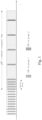
Fig. 1 shows an example of SSS group switching; -
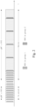
Fig. 2 shows another example of SSS group switching; -
Fig. 3 shows an exemplary UE. - In a New Radio - Unlicensed spectrum (NR-U) system, a UE can be provided with two groups of Search Space Sets (SSS) for PDCCH monitoring. The UE may switch PDCCH monitoring from
group 1 togroup 2 or fromgroup 2 togroup 1 during different monitoring phases.SSS group 1 may be called as search space sets with group index 0, andSSS group 2 may be called as search space sets withgroup index 1. Further,SSS group 1 may be called as a first SSS group, andSSS group 2 may be called as a second SSS group. For example, as shown inFig. 1 , a UE may monitor PDCCH in search space sets ingroup 1 outside a gNB's channel occupancy (CO) and may switch to monitor PDCCH in search space sets ingroup 2 when the UE finds that the gNB acquires the channel occupancy. Note that there could be a switch delay for PDCCH monitoring switching, e.g., fromgroup 1 togroup 2 and/or fromgroup 2 togroup 1. - In some cases, a gNB may not want a UE to switch groups even the gNB acquires a channel occupancy in an unlicensed carrier, for example, the gNB only intends to have a short CO or the gNB intends to start another CO soon after. As shown in
Fig. 2 as an example, the gNB may start a short CO, e.g.,COT 1 to transmit high priority signal(s)/channel(s), e.g., a Synchronization Signal Block (SSB), and during this COT1, the gNB does not want the UE to switch PDCCH monitoring group. After that, the gNB may plan to have a longer CO, e.g.,COT 2 and may want the UE to switch PDCCH monitoring group. - The present disclosure addresses the conditions when the UE can switch from PDCCH monitoring in search space sets in
group 1 to PDCCH monitoring in search space sets ingroup 2, and/or the conditions when the UE can switch from PDCCH monitoring in search space sets ingroup 2 to PDCCH monitoring in search space sets ingroup 1. - The following solutions is provided.
- Step 1: UE may determine a threshold and/or a COT duration;
- Step 2: UE may switch PDCCH monitoring groups based on the threshold and/or the COT duration.
- Optionally, all the optional solutions in the present disclosure can be (Radio Resource Control (RRC) configured if they are not mutual exclusion. In particular, all the parameters such as the threshold and the COT duration may be RRC configured. In such a case, the UE may determine the threshold and/or the COT duration means that the UE may receive information about the threshold and/or the COT duration through an RRC message from a base station, e.g., an eNB or a gNB, so that the UE can determine the threshold and/or the COT duration based on the received RRC message.
- Optionally, the step of UE determining the threshold may include at least one of the followings:
- The threshold may be predefined, e.g., specified in the specification.
- The threshold may be RRC configured, or the threshold may be determined according to a configured RRC parameter, for example, a parameter searchSpaceSwitchTimer in an RRC information element PDCCH-ServingCellConfig.
- The threshold may be indicated through Downlink Control Information (DCI), or the threshold may be determined according to a parameter in DCI.
- The threshold may be indicated through a Media Access Control Control Element (MAC CE), or the threshold may be determined according to a parameter in a MAC CE.
- The threshold may be determined from a threshold set.
- Optionally, the threshold set could be a configured/predefined threshold table.
- Optionally, different threshold values in the threshold set can be used for different cases.
- Optionally, different threshold values in the threshold set can be used for different subcarrier spacings.
- When the threshold is RRC configured or determined according to a configured RRC parameter, the base station may determine the threshold from a threshold set and then send information about the determined threshold through an RRC message to the UE, e.g., through a parameter searchSpaceSwitchTimer in an RRC information element PDCCH-ServingCellConfig. In this case, the threshold set may include different threshold values for different subcarrier spacings.
- Optionally, the threshold may be determined in the unit of at least one of: symbol, slot, subframe, frame, microsecond, millisecond, second. That is, the threshold is a time threshold with a value in time, e.g., as a timer value for a timer.
- Optionally, UE may determine the COT duration according to a DCI format 2_0.
- Optionally, UE may determine the COT duration according to a COT duration indication and/or an SFI indication.
- E.g., the COT duration indication and/or the SFI indication can be transmitted in DCI format 2_0.
- Optionally, the COT duration could be the remaining COT duration or the total COT duration.
- UE switches PDCCH monitoring groups based on the threshold and the COT duration, this may include
- If UE determines that the COT duration is longer than or equal to the threshold, the UE may switch PDCCH monitoring groups, and/or,
- If UE determines the COT duration is shorter than or equal to the threshold, the UE may not switch PDCCH monitoring groups. UE switches PDCCH monitoring groups based on the threshold and/or the COT duration, this may include
- A COT end position is determined based on the COT duration, and the UE may switch PDCCH monitoring groups based on the threshold and the COT end position. Optionally,
- o The UE may not switch PDCCH monitoring groups within the time duration which equals to the threshold after the COT end position, and/or,
- o The UE may switch PDCCH monitoring groups outside the time duration which equals to the threshold after the COT end position.
- Optionally, PDCCH monitoring group switching from
group 1 togroup 2 and fromgroup 2 togroup 1 may fulfill different conditions. - UE is provided a switch delay for PDCCH monitoring switching, e.g., from
group 1 togroup 2 and/or fromgroup 2 togroup 1. - E.g., the switch delay could be a slot boundary or next available slot boundary that is at least N symbols later than a starting position. That is, a PDCCH monitoring switching may be delayed to the slot boundary or the next available slot boundary that is at least N symbols later than the starting position.
- E.g., the starting position could be the last symbol of a detected DCI format, i.e., the last symbol of the PDCCH with the DCI format.
- E.g., the starting position could be the last symbol of a detected DCI with specified DCI format, i.e., the last symbol of the PDCCH with the specified DCI format.
- ∘ The specified DCI format could be DCI format 2_0, or a UE-specific DCI format, or a common DCI format.
- ∘ The specified DCI format could be DCI format in a specified group, e.g.,
group 1.
- E.g., the starting position may be a slot where a timer that has been set with the time threshold expires. UE switches PDCCH monitoring groups based on the threshold and the COT duration, including at least one of the following:
- The UE may switch from
group 1 togroup 2 when after detection of any PDCCH ingroup 1 at a slot boundary (or next available slot boundary) that is at least N symbols later than the last symbol of the detected PDCCH ingroup 1, if the COT duration is longer than or equal to the threshold. - The UE may not switch from
group 1 togroup 2 when after detection of any PDCCH ingroup 1 at a slot boundary (or next available slot boundary) that is at least N symbols later than the last symbol of the detected PDCCH ingroup 1, if the COT duration is shorter than or equal to the threshold. - The UE may also switch from
group 1 togroup 2 when after detection of any DCI format 2_0 ingroup 1 at a slot boundary (or next available slot boundary) that is at least N symbols later than the last symbol of the detected PDCCH ingroup 1, if the COT duration is longer than or equal to the threshold. - The UE may not switch from
group 1 togroup 2 when after detection of any DCI format 2_0 in group1 at a slot boundary (or next available slot boundary) that is at least N symbols later than the last symbol of the detected PDCCH ingroup 1, if the COT duration is shorter than or equal to the threshold.
- The UE may switch from
- Optionally, UE may also switch PDCCH monitoring groups under other conditions. E.g., UE may switch PDCCH monitoring groups under at least one of the followings:
- UE may also may switch PDCCH monitoring groups based on a monitoring group flag in DCI format 2_0.
- UE may also may switch PDCCH monitoring groups based on a detection of any PDCCH in group1, e.g., a detection of a DCI format in a PDCCH.
- UE may also switch PDCCH monitoring groups if no PDCCH is detected in group2 for a configurable time.
- Optionally, the behavior of PDCCH monitoring group switching can be RRC configured.
- Example 1: UE can be RRC configured with at least one of the following behaviors for PDCCH group switching from
group 1 to group 2: - UE may also switch PDCCH monitoring groups based on the threshold and/or the COT duration.
- UE may also switch PDCCH monitoring groups based on a monitoring group flag in DCI format 2_0.
- UE may also switch PDCCH monitoring groups based on a detection of any PDCCH in
group 1, e.g., detection of a DCI format 2_0 in a PDCCH. - Optionally, a UE may, e.g. after switching from
group 1 togroup 2, set the value of a timer as the threshold, and then decrement the value of the timer by one after each time unit, e.g., a time unit of symbol, slot, subframe, frame, microsecond, millisecond, or second. - Example 2: UE can be RRC configured with at least one of the following behaviors for PDCCH group switching from
group 2 to group 1: - UE may also switch PDCCH monitoring groups based on the threshold and/or the COT end position. For example, UE may switch PDCCH monitoring groups when the timer set with the threshold expires. For example, UE may switch PDCCH monitoring groups after the end of the COT duration, i.e., after the COT end position.
- UE may also switch PDCCH monitoring groups if no PDCCH is detected in group2 for a configurable time.
- In summary, it is provided a method of PDCCH monitoring in NR-U. With this method, a UE can determine when to switch PDCCH monitoring groups without extra signaling overhead, and avoid frequently switching PDCCH monitoring groups especially when a gNB does not want the UE to switch PDCCH monitoring group. Implementation complexity at UE side can be reduced.
- The technical mechanisms provided by the present disclosure could be adopted in the 5G NR unlicensed band communications.
- In addition, it is provided UE that is configured to perform one of the above methods.
- The UE may comprises one or more storage medium storing computer readable instructions, and one or more computing processors configured to execute the computer readable instructions for performing one of the above methods, for example as shown in
Fig. 3 . - The UE may comprise a plurality of modules, each module is configured to perform one or more of method steps to complete one of above methods.
- It is provided a computer program, comprising instructions, when executed by user equipment, for causing the user equipment to perform one of the above methods.
- It is provided a computer readable medium, comprising instructions for causing a user equipment to perform one of the above methods.
Claims (17)
- A method for Physical Downlink Control Channel, PDCCH, monitoring, performed by User Equipment, UE, comprising:being provided a first switching delay before a first switching step and after a first condition is fulfilled, wherein the first switching delay refers to a next available slot boundary that is at least N symbols later than a first starting position, wherein N is a positive integer, and the first starting position is a slot where a timer that has been set to a timer value expires;the first switching step, comprising: switching from monitoring a PDCCH of a serving cell according to a second Search Space Set, SSS, group to monitoring the PDCCH according to a first SSS group, under the first condition based on a time threshold and/or based on a Channel Occupancy Time, COT, duration acquired by a base station of a serving cell;being provided a second switching delay before a second switching step and after a second condition is fulfilled, wherein the second switching delay refers to another next available slot boundary that is at least N symbols later than a second starting position, and the second starting position is a last symbol of a detected PDCCH with a detected Downlink Control information, DCI, format 2_0; andthe second switching step, comprising: switching from monitoring the PDCCH according to the first SSS group to monitoring the PDCCH according to the second SSS group, under the second condition based on a monitoring group flag in the detected DCI format 2_0, and/or a detection of a PDCCH by monitoring the PDCCH according to the first SSS group,wherein the time threshold is the timer value in a unit of slot, whereinunder the first condition based on the time threshold comprises: a condition of after the timer that has been set to the timer value expires.
- The method of claim 1, whereinthe time threshold is configured through Radio Resource Control, RRC, by the base station, whereinunder the first condition based on the COT duration occupied by the base station of the serving cell further comprising: a condition of after a COT end position of the COT duration.
- The method of claim 1, wherein
the first switching delay and/or the second switching delay is configured through Radio Resource Control, RRC, by the base station. - The method of claim 1, wherein
the COT duration is indicated in an RRC information element Slot Format Indicator, SFI. - The method of claim 1, wherein
information indicating the COT duration is transmitted in a Downlink Control Information, DCI, format 2_0. - The method of claim 1, wherein
the timer value is configured through Radio Resource Control, RRC, by the base station. - The method of claim 6, wherein
the timer value is indicated by a parameter searchSpaceSwitchTimer in an RRC information element PDCCH-ServingCellConfig. - A method for Physical Downlink Control Channel, PDCCH, monitoring, performed by a base station, comprising:providing a first switching delay and a first condition to user equipment, UE, wherein the first switching delay refers to a next available slot boundary that is at least N symbols later than a first starting position, wherein N is a positive integer, and the first starting position is a slot where a timer that has been set to a timer value expires;providing a second switching delay and a second condition to the UE, wherein the second switching delay refers to another next available slot boundary that is at least N symbols later than a second starting position, and the second starting position is a last symbol of a detected PDCCH with a detected Downlink Control information, DCI, format 2_0;providing the UE with a time threshold and/or a Channel Occupancy Time, COT, duration acquired by the base station, wherein the time threshold and/or the COT duration allows the UE to perform:being provided the first switching delay before a first switching step and after the first condition is fulfilled;the first switching step, comprising: switching from monitoring a PDCCH of a serving cell according to a second Search Space Set, SSS, group to monitoring the PDCCH according to a first SSS group, under the first condition based on the time threshold and/or based on the COT duration;being provided the second switching delay before a second switching step and after the second condition is fulfilled;the second switching step, comprising: switching from monitoring the PDCCH according to the first SSS group to monitoring the PDCCH according to the second SSS group, under the second condition based on a monitoring group flag in the detected DCI format 2_0, and/or a detection of a PDCCH by monitoring the PDCCH according to the first SSS group, wherein the time threshold is determined from a threshold set;wherein the time threshold is the timer value in a unit of slot, whereinunder the first condition based on the time threshold comprises: a condition of after the timer that has been set to the timer value expires.
- The method of claim 8, wherein
different time thresholds in the threshold set are used for different subcarrier spacings. - The method of claim 8, wherein
the threshold set is a predefined threshold table. - The method of claim 8, wherein
the time threshold is transmitted through a Radio Resource Control, RRC, message to the UE. - The method of claim 11, wherein
the time threshold is indicated by a parameter searchSpaceSwitchTimer in an RRC information element PDCCH-ServingCellConfig. - The method of claim 8, wherein
the COT duration is indicated in an RRC information element Slot Format Indicator, SFI. - The method of claim 8, wherein
information indicating the COT duration is transmitted in a Downlink Control Information, DCI, format 2_0. - The method of claim 8, being a method of PDCCH monitoring in a New Radio - Unlicensed spectrum, NR-U, system.
- User equipment, UE, configured to perform:being provided a first switching delay before a first switching and after a first condition is fulfilled, wherein the first switching delay refers to a next available slot boundary that is at least N symbols later than a first starting position, wherein N is a positive integer, and the first starting position is a slot where a timer that has been set to a timer value expires;the first switching step, comprising switching from monitoring a Physical Downlink Control Channel, PDCCH, of a serving cell according to a second Search Space Set, SSS, group to monitoring the PDCCH according to a first SSS group, under the first condition based on a time threshold and/or based on a Channel Occupancy Time, COT, duration acquired by a base station of a serving cell;being provided a second switching delay before a second switching and after a second condition is fulfilled, wherein the second switching delay refers to another next available slot boundary that is at least N symbols later than a second starting position, and the second starting position is a last symbol of a detected PDCCH with a detected Downlink Control information, DCI, format 2_0; andthe second switching step, comprising: switching from monitoring the PDCCH according to the first SSS group to monitoring the PDCCH according to the second SSS group, under the second condition based on a monitoring group flag in the detected DCI format 2_0, and/or a detection of a PDCCH by monitoring the PDCCH according to the first SSS group;wherein the time threshold is the timer value in a unit of slot, whereinunder the first condition based on the time threshold comprises: a condition of after the timer that has been set to the timer value expires.
- A base station, configured to perform:providing a first switching delay and a first condition to user equipment, UE, wherein the first switching delay refers to a next available slot boundary that is at least N symbols later than a first starting position, wherein N is a positive integer, and the first starting position is a slot where a timer that has been set to a timer value expires;providing a second switching delay and a second condition to the UE, wherein the second switching delay refers to another next available slot boundary that is at least N symbols later than a second starting position, and the second starting position is a last symbol of a detected Physical Downlink Control Channel, PDCCH, with a detected Downlink Control information, DCI, format 2_0;providing the UE with a time threshold and/or a Channel Occupancy Time, COT, duration acquired by the base station, wherein the time threshold and/or the COT duration allows the UE to perform:being provided the first switching delay before a first switching step and after the first condition is fulfilled;the first switching step, comprising: switching from monitoring a PDCCH of a serving cell according to a second Search Space Set (SSS) group to monitoring the PDCCH according to a first SSS group, under the first condition based on the time threshold and/or based on the COT duration;being provided the second switching delay before a second switching step and after the second condition is fulfilled;the second switching step, comprising: switching from monitoring the PDCCH according to the first SSS group to monitoring the PDCCH according to the second SSS group, under the second condition based on a monitoring group flag in the detected DCI format 2_0, and/or a detection of a PDCCH by monitoring the PDCCH according to the first SSS group, wherein the time threshold is determined from a threshold set;wherein the time threshold is the timer value in a unit of slot, whereinunder the first condition based on the time threshold comprises: a condition of after the timer that has been set to the timer value expires.
Applications Claiming Priority (2)
| Application Number | Priority Date | Filing Date | Title |
|---|---|---|---|
| US201962938930P | 2019-11-21 | 2019-11-21 | |
| PCT/CN2020/130675 WO2021098863A1 (en) | 2019-11-21 | 2020-11-20 | Methods for pdcch monitoring, user equipment, base station, and computer readable media |
Publications (3)
| Publication Number | Publication Date |
|---|---|
| EP4042829A1 EP4042829A1 (en) | 2022-08-17 |
| EP4042829A4 EP4042829A4 (en) | 2022-11-30 |
| EP4042829B1 true EP4042829B1 (en) | 2024-11-06 |
Family
ID=75980426
Family Applications (1)
| Application Number | Title | Priority Date | Filing Date |
|---|---|---|---|
| EP20889771.0A Active EP4042829B1 (en) | 2019-11-21 | 2020-11-20 | Methods for pdcch monitoring, user equipment, base station, and computer readable media |
Country Status (4)
| Country | Link |
|---|---|
| US (1) | US12193056B2 (en) |
| EP (1) | EP4042829B1 (en) |
| CN (2) | CN114342551A (en) |
| WO (1) | WO2021098863A1 (en) |
Families Citing this family (3)
| Publication number | Priority date | Publication date | Assignee | Title |
|---|---|---|---|---|
| CN115885548B (en) * | 2020-06-28 | 2025-03-11 | 高通股份有限公司 | Method and apparatus for dynamic PDCCH monitoring group switching |
| CN117835402A (en) * | 2022-09-28 | 2024-04-05 | 北京三星通信技术研究有限公司 | Communication method and electronic device |
| US20250151082A1 (en) * | 2023-11-06 | 2025-05-08 | Qualcomm Incorporated | Event-based search space set group (sssg) switching and physical downlink control channel (pdcch) skipping |
Family Cites Families (13)
| Publication number | Priority date | Publication date | Assignee | Title |
|---|---|---|---|---|
| KR102035918B1 (en) * | 2017-02-10 | 2019-10-23 | 아서스테크 컴퓨터 인코포레이션 | Method and apparatus for control channel transmission in a wireless communication system |
| EP3989460B1 (en) * | 2017-06-14 | 2024-01-03 | Sony Group Corporation | Apparatus and method for determining whether to provide a csi report |
| EP3711450A1 (en) * | 2017-11-17 | 2020-09-23 | Nokia Technologies Oy | Control monitoring upon receipt of discontinuous reception trigger |
| EP3525542B1 (en) * | 2018-02-07 | 2020-04-29 | ASUSTek Computer Inc. | Method and apparatus for monitoring interrupted transmission indication in a wireless communication system |
| CN110351874B (en) * | 2018-04-03 | 2021-07-23 | 北京紫光展锐通信技术有限公司 | Method, device, base station and user equipment for notifying channel occupation time |
| US11265128B2 (en) * | 2018-04-30 | 2022-03-01 | Qualcomm Incorporated | Search space set occasion level mapping for PDCCH overbooking |
| CN110475317B (en) * | 2018-05-10 | 2021-02-09 | 维沃移动通信有限公司 | PDCCH monitoring method, terminal device and network side device |
| US11291025B2 (en) * | 2019-07-16 | 2022-03-29 | Qualcomm Incorporated | Remaining channel occupancy time indications |
| CN112788671A (en) * | 2019-11-06 | 2021-05-11 | 维沃移动通信有限公司 | Method and device for detecting physical downlink control channel |
| CN114902770B (en) * | 2019-11-08 | 2025-09-05 | 瑞典爱立信有限公司 | Method for control channel monitoring for switching search space set groups |
| WO2021097692A1 (en) * | 2019-11-20 | 2021-05-27 | Qualcomm Incorporated | Managing control channel monitoring |
| EP4464082A1 (en) * | 2022-01-14 | 2024-11-20 | Ofinno, LLC | Uplink transmission with a base station in energy saving state |
| US20240267932A1 (en) * | 2023-02-03 | 2024-08-08 | Samsung Electronics Co., Ltd. | Pdcch monitoring adaptation for operation in full-duplex systems |
-
2020
- 2020-11-20 EP EP20889771.0A patent/EP4042829B1/en active Active
- 2020-11-20 WO PCT/CN2020/130675 patent/WO2021098863A1/en not_active Ceased
- 2020-11-20 CN CN202080062880.9A patent/CN114342551A/en active Pending
- 2020-11-20 CN CN202210832820.1A patent/CN115001641B/en active Active
-
2022
- 2022-05-04 US US17/736,994 patent/US12193056B2/en active Active
Also Published As
| Publication number | Publication date |
|---|---|
| WO2021098863A1 (en) | 2021-05-27 |
| US20220264649A1 (en) | 2022-08-18 |
| CN115001641A (en) | 2022-09-02 |
| CN114342551A (en) | 2022-04-12 |
| EP4042829A1 (en) | 2022-08-17 |
| EP4042829A4 (en) | 2022-11-30 |
| US12193056B2 (en) | 2025-01-07 |
| CN115001641B (en) | 2024-02-23 |
Similar Documents
| Publication | Publication Date | Title |
|---|---|---|
| EP3096481B1 (en) | Signal transmission method and apparatus | |
| CN110351874B (en) | Method, device, base station and user equipment for notifying channel occupation time | |
| US11323226B2 (en) | Method for allocating control resource set, method for acquiring control resource set, base station, user equipment and readable medium | |
| US20120307777A1 (en) | Method, system and device for scheduling non-contention based random access and transmitting preamble | |
| US20180310282A1 (en) | Downlink control method and apparatus | |
| US12193056B2 (en) | Methods for PDCCH monitoring, user equipment, and base station | |
| EP3820187A1 (en) | Unlicensed channel sharing method and device, storage medium, terminal and base station | |
| US9820219B2 (en) | Wireless communication system, terminal apparatus, wireless communication method, and integrated circuit | |
| CN110138500A (en) | Method and device for detecting downlink control information and user equipment | |
| KR20170077198A (en) | Information transmission method, user equipment, and base station | |
| EP3482600B1 (en) | Method for facilitating clear channel assessment and radio unit | |
| US10869326B2 (en) | Scheduling information transmission method and apparatus | |
| US10313863B2 (en) | Downlink emergency service transmission method, base station, user equipment, and system | |
| EP3700270A1 (en) | Control information sending method, detection method, network device, and terminal | |
| EP2921020B1 (en) | Methods and apparatuses for enabling cell activation in a network | |
| KR20200003820A (en) | Method and apparatus for discontinuous reception | |
| US10645723B2 (en) | Signal transmission method, signal transmission control method, user equipment, and base station | |
| US12034507B2 (en) | Method and device for channel state indication on unlicensed spectrum | |
| CN105939187A (en) | Sounding reference signal enhancement method under unlicensed spectrum and related equipment | |
| US12507278B2 (en) | Method and apparatus for control channel design for data transmission on unlicensed spectrum | |
| US12063532B2 (en) | PDCCH transmission in wireless communications | |
| EP3827628B1 (en) | Method and device for indicating pdcch resources | |
| WO2016151389A1 (en) | A wireless communication method for activating a secondary carrier | |
| HK40027509A (en) | Control information sending method, detection method, network device, and terminal |
Legal Events
| Date | Code | Title | Description |
|---|---|---|---|
| STAA | Information on the status of an ep patent application or granted ep patent |
Free format text: STATUS: THE INTERNATIONAL PUBLICATION HAS BEEN MADE |
|
| PUAI | Public reference made under article 153(3) epc to a published international application that has entered the european phase |
Free format text: ORIGINAL CODE: 0009012 |
|
| STAA | Information on the status of an ep patent application or granted ep patent |
Free format text: STATUS: REQUEST FOR EXAMINATION WAS MADE |
|
| 17P | Request for examination filed |
Effective date: 20220503 |
|
| AK | Designated contracting states |
Kind code of ref document: A1 Designated state(s): AL AT BE BG CH CY CZ DE DK EE ES FI FR GB GR HR HU IE IS IT LI LT LU LV MC MK MT NL NO PL PT RO RS SE SI SK SM TR |
|
| REG | Reference to a national code |
Ref country code: DE Ref legal event code: R079 Free format text: PREVIOUS MAIN CLASS: H04W0076280000 Ipc: H04L0005000000 Ref country code: DE Ref legal event code: R079 Ref document number: 602020041072 Country of ref document: DE Free format text: PREVIOUS MAIN CLASS: H04W0076280000 Ipc: H04L0005000000 |
|
| A4 | Supplementary search report drawn up and despatched |
Effective date: 20221102 |
|
| RIC1 | Information provided on ipc code assigned before grant |
Ipc: H04W 76/28 20180101ALI20221026BHEP Ipc: H04L 5/00 20060101AFI20221026BHEP |
|
| DAV | Request for validation of the european patent (deleted) | ||
| DAX | Request for extension of the european patent (deleted) | ||
| STAA | Information on the status of an ep patent application or granted ep patent |
Free format text: STATUS: EXAMINATION IS IN PROGRESS |
|
| 17Q | First examination report despatched |
Effective date: 20230711 |
|
| GRAP | Despatch of communication of intention to grant a patent |
Free format text: ORIGINAL CODE: EPIDOSNIGR1 |
|
| STAA | Information on the status of an ep patent application or granted ep patent |
Free format text: STATUS: GRANT OF PATENT IS INTENDED |
|
| INTG | Intention to grant announced |
Effective date: 20240705 |
|
| GRAS | Grant fee paid |
Free format text: ORIGINAL CODE: EPIDOSNIGR3 |
|
| GRAA | (expected) grant |
Free format text: ORIGINAL CODE: 0009210 |
|
| STAA | Information on the status of an ep patent application or granted ep patent |
Free format text: STATUS: THE PATENT HAS BEEN GRANTED |
|
| AK | Designated contracting states |
Kind code of ref document: B1 Designated state(s): AL AT BE BG CH CY CZ DE DK EE ES FI FR GB GR HR HU IE IS IT LI LT LU LV MC MK MT NL NO PL PT RO RS SE SI SK SM TR |
|
| REG | Reference to a national code |
Ref country code: GB Ref legal event code: FG4D |
|
| REG | Reference to a national code |
Ref country code: CH Ref legal event code: EP |
|
| REG | Reference to a national code |
Ref country code: DE Ref legal event code: R096 Ref document number: 602020041072 Country of ref document: DE |
|
| REG | Reference to a national code |
Ref country code: IE Ref legal event code: FG4D |
|
| REG | Reference to a national code |
Ref country code: LT Ref legal event code: MG9D |
|
| REG | Reference to a national code |
Ref country code: NL Ref legal event code: MP Effective date: 20241106 |
|
| P01 | Opt-out of the competence of the unified patent court (upc) registered |
Free format text: CASE NUMBER: APP_9742/2025 Effective date: 20250226 |
|
| PG25 | Lapsed in a contracting state [announced via postgrant information from national office to epo] |
Ref country code: PT Free format text: LAPSE BECAUSE OF FAILURE TO SUBMIT A TRANSLATION OF THE DESCRIPTION OR TO PAY THE FEE WITHIN THE PRESCRIBED TIME-LIMIT Effective date: 20250306 Ref country code: IS Free format text: LAPSE BECAUSE OF FAILURE TO SUBMIT A TRANSLATION OF THE DESCRIPTION OR TO PAY THE FEE WITHIN THE PRESCRIBED TIME-LIMIT Effective date: 20250306 Ref country code: HR Free format text: LAPSE BECAUSE OF FAILURE TO SUBMIT A TRANSLATION OF THE DESCRIPTION OR TO PAY THE FEE WITHIN THE PRESCRIBED TIME-LIMIT Effective date: 20241106 |
|
| PG25 | Lapsed in a contracting state [announced via postgrant information from national office to epo] |
Ref country code: FI Free format text: LAPSE BECAUSE OF FAILURE TO SUBMIT A TRANSLATION OF THE DESCRIPTION OR TO PAY THE FEE WITHIN THE PRESCRIBED TIME-LIMIT Effective date: 20241106 Ref country code: NL Free format text: LAPSE BECAUSE OF FAILURE TO SUBMIT A TRANSLATION OF THE DESCRIPTION OR TO PAY THE FEE WITHIN THE PRESCRIBED TIME-LIMIT Effective date: 20241106 |
|
| REG | Reference to a national code |
Ref country code: AT Ref legal event code: MK05 Ref document number: 1740565 Country of ref document: AT Kind code of ref document: T Effective date: 20241106 |
|
| PG25 | Lapsed in a contracting state [announced via postgrant information from national office to epo] |
Ref country code: BG Free format text: LAPSE BECAUSE OF FAILURE TO SUBMIT A TRANSLATION OF THE DESCRIPTION OR TO PAY THE FEE WITHIN THE PRESCRIBED TIME-LIMIT Effective date: 20241106 |
|
| PG25 | Lapsed in a contracting state [announced via postgrant information from national office to epo] |
Ref country code: ES Free format text: LAPSE BECAUSE OF FAILURE TO SUBMIT A TRANSLATION OF THE DESCRIPTION OR TO PAY THE FEE WITHIN THE PRESCRIBED TIME-LIMIT Effective date: 20241106 |
|
| PG25 | Lapsed in a contracting state [announced via postgrant information from national office to epo] |
Ref country code: NO Free format text: LAPSE BECAUSE OF FAILURE TO SUBMIT A TRANSLATION OF THE DESCRIPTION OR TO PAY THE FEE WITHIN THE PRESCRIBED TIME-LIMIT Effective date: 20250206 |
|
| PG25 | Lapsed in a contracting state [announced via postgrant information from national office to epo] |
Ref country code: GR Free format text: LAPSE BECAUSE OF FAILURE TO SUBMIT A TRANSLATION OF THE DESCRIPTION OR TO PAY THE FEE WITHIN THE PRESCRIBED TIME-LIMIT Effective date: 20250207 Ref country code: LV Free format text: LAPSE BECAUSE OF FAILURE TO SUBMIT A TRANSLATION OF THE DESCRIPTION OR TO PAY THE FEE WITHIN THE PRESCRIBED TIME-LIMIT Effective date: 20241106 Ref country code: AT Free format text: LAPSE BECAUSE OF FAILURE TO SUBMIT A TRANSLATION OF THE DESCRIPTION OR TO PAY THE FEE WITHIN THE PRESCRIBED TIME-LIMIT Effective date: 20241106 |
|
| PG25 | Lapsed in a contracting state [announced via postgrant information from national office to epo] |
Ref country code: PL Free format text: LAPSE BECAUSE OF FAILURE TO SUBMIT A TRANSLATION OF THE DESCRIPTION OR TO PAY THE FEE WITHIN THE PRESCRIBED TIME-LIMIT Effective date: 20241106 |
|
| PG25 | Lapsed in a contracting state [announced via postgrant information from national office to epo] |
Ref country code: RS Free format text: LAPSE BECAUSE OF FAILURE TO SUBMIT A TRANSLATION OF THE DESCRIPTION OR TO PAY THE FEE WITHIN THE PRESCRIBED TIME-LIMIT Effective date: 20250206 |
|
| REG | Reference to a national code |
Ref country code: CH Ref legal event code: PL |
|
| PG25 | Lapsed in a contracting state [announced via postgrant information from national office to epo] |
Ref country code: SM Free format text: LAPSE BECAUSE OF FAILURE TO SUBMIT A TRANSLATION OF THE DESCRIPTION OR TO PAY THE FEE WITHIN THE PRESCRIBED TIME-LIMIT Effective date: 20241106 |
|
| PG25 | Lapsed in a contracting state [announced via postgrant information from national office to epo] |
Ref country code: DK Free format text: LAPSE BECAUSE OF FAILURE TO SUBMIT A TRANSLATION OF THE DESCRIPTION OR TO PAY THE FEE WITHIN THE PRESCRIBED TIME-LIMIT Effective date: 20241106 |
|
| PG25 | Lapsed in a contracting state [announced via postgrant information from national office to epo] |
Ref country code: LU Free format text: LAPSE BECAUSE OF NON-PAYMENT OF DUE FEES Effective date: 20241120 |
|
| REG | Reference to a national code |
Ref country code: CH Ref legal event code: PL |
|
| PG25 | Lapsed in a contracting state [announced via postgrant information from national office to epo] |
Ref country code: EE Free format text: LAPSE BECAUSE OF FAILURE TO SUBMIT A TRANSLATION OF THE DESCRIPTION OR TO PAY THE FEE WITHIN THE PRESCRIBED TIME-LIMIT Effective date: 20241106 |
|
| PG25 | Lapsed in a contracting state [announced via postgrant information from national office to epo] |
Ref country code: CH Free format text: LAPSE BECAUSE OF NON-PAYMENT OF DUE FEES Effective date: 20241130 |
|
| PG25 | Lapsed in a contracting state [announced via postgrant information from national office to epo] |
Ref country code: RO Free format text: LAPSE BECAUSE OF FAILURE TO SUBMIT A TRANSLATION OF THE DESCRIPTION OR TO PAY THE FEE WITHIN THE PRESCRIBED TIME-LIMIT Effective date: 20241106 |
|
| PG25 | Lapsed in a contracting state [announced via postgrant information from national office to epo] |
Ref country code: SK Free format text: LAPSE BECAUSE OF FAILURE TO SUBMIT A TRANSLATION OF THE DESCRIPTION OR TO PAY THE FEE WITHIN THE PRESCRIBED TIME-LIMIT Effective date: 20241106 |
|
| PG25 | Lapsed in a contracting state [announced via postgrant information from national office to epo] |
Ref country code: CZ Free format text: LAPSE BECAUSE OF FAILURE TO SUBMIT A TRANSLATION OF THE DESCRIPTION OR TO PAY THE FEE WITHIN THE PRESCRIBED TIME-LIMIT Effective date: 20241106 |
|
| PG25 | Lapsed in a contracting state [announced via postgrant information from national office to epo] |
Ref country code: IT Free format text: LAPSE BECAUSE OF FAILURE TO SUBMIT A TRANSLATION OF THE DESCRIPTION OR TO PAY THE FEE WITHIN THE PRESCRIBED TIME-LIMIT Effective date: 20241106 |
|
| REG | Reference to a national code |
Ref country code: DE Ref legal event code: R097 Ref document number: 602020041072 Country of ref document: DE |
|
| REG | Reference to a national code |
Ref country code: BE Ref legal event code: MM Effective date: 20241130 |
|
| PG25 | Lapsed in a contracting state [announced via postgrant information from national office to epo] |
Ref country code: SE Free format text: LAPSE BECAUSE OF FAILURE TO SUBMIT A TRANSLATION OF THE DESCRIPTION OR TO PAY THE FEE WITHIN THE PRESCRIBED TIME-LIMIT Effective date: 20241106 |
|
| PLBE | No opposition filed within time limit |
Free format text: ORIGINAL CODE: 0009261 |
|
| STAA | Information on the status of an ep patent application or granted ep patent |
Free format text: STATUS: NO OPPOSITION FILED WITHIN TIME LIMIT |
|
| PG25 | Lapsed in a contracting state [announced via postgrant information from national office to epo] |
Ref country code: MC Free format text: LAPSE BECAUSE OF FAILURE TO SUBMIT A TRANSLATION OF THE DESCRIPTION OR TO PAY THE FEE WITHIN THE PRESCRIBED TIME-LIMIT Effective date: 20241106 |
|
| 26N | No opposition filed |
Effective date: 20250807 |
|
| PG25 | Lapsed in a contracting state [announced via postgrant information from national office to epo] |
Ref country code: BE Free format text: LAPSE BECAUSE OF NON-PAYMENT OF DUE FEES Effective date: 20241130 |
|
| PG25 | Lapsed in a contracting state [announced via postgrant information from national office to epo] |
Ref country code: IE Free format text: LAPSE BECAUSE OF NON-PAYMENT OF DUE FEES Effective date: 20241120 |
|
| PGFP | Annual fee paid to national office [announced via postgrant information from national office to epo] |
Ref country code: DE Payment date: 20251124 Year of fee payment: 6 |
|
| PGFP | Annual fee paid to national office [announced via postgrant information from national office to epo] |
Ref country code: GB Payment date: 20251126 Year of fee payment: 6 |
|
| PGFP | Annual fee paid to national office [announced via postgrant information from national office to epo] |
Ref country code: FR Payment date: 20251126 Year of fee payment: 6 |
|
| PG25 | Lapsed in a contracting state [announced via postgrant information from national office to epo] |
Ref country code: HU Free format text: LAPSE BECAUSE OF FAILURE TO SUBMIT A TRANSLATION OF THE DESCRIPTION OR TO PAY THE FEE WITHIN THE PRESCRIBED TIME-LIMIT; INVALID AB INITIO Effective date: 20201120 |