EP4042639B1 - Ausführung von mehrpfadkommunikation - Google Patents
Ausführung von mehrpfadkommunikation Download PDFInfo
- Publication number
- EP4042639B1 EP4042639B1 EP19800986.2A EP19800986A EP4042639B1 EP 4042639 B1 EP4042639 B1 EP 4042639B1 EP 19800986 A EP19800986 A EP 19800986A EP 4042639 B1 EP4042639 B1 EP 4042639B1
- Authority
- EP
- European Patent Office
- Prior art keywords
- data packets
- communication device
- packet
- data
- sequence number
- Prior art date
- Legal status (The legal status is an assumption and is not a legal conclusion. Google has not performed a legal analysis and makes no representation as to the accuracy of the status listed.)
- Active
Links
Images




Classifications
-
- H—ELECTRICITY
- H04—ELECTRIC COMMUNICATION TECHNIQUE
- H04L—TRANSMISSION OF DIGITAL INFORMATION, e.g. TELEGRAPHIC COMMUNICATION
- H04L45/00—Routing or path finding of packets in data switching networks
- H04L45/24—Multipath
-
- H—ELECTRICITY
- H04—ELECTRIC COMMUNICATION TECHNIQUE
- H04L—TRANSMISSION OF DIGITAL INFORMATION, e.g. TELEGRAPHIC COMMUNICATION
- H04L45/00—Routing or path finding of packets in data switching networks
- H04L45/34—Source routing
-
- H—ELECTRICITY
- H04—ELECTRIC COMMUNICATION TECHNIQUE
- H04L—TRANSMISSION OF DIGITAL INFORMATION, e.g. TELEGRAPHIC COMMUNICATION
- H04L47/00—Traffic control in data switching networks
- H04L47/10—Flow control; Congestion control
- H04L47/34—Flow control; Congestion control ensuring sequence integrity, e.g. using sequence numbers
-
- H—ELECTRICITY
- H04—ELECTRIC COMMUNICATION TECHNIQUE
- H04W—WIRELESS COMMUNICATION NETWORKS
- H04W40/00—Communication routing or communication path finding
- H04W40/24—Connectivity information management, e.g. connectivity discovery or connectivity update
Definitions
- the present disclosure relates generally to the field of wireless communication technologies; and more specifically, to methods and devices for executing multipath communication.
- a cellular communication may be used to communicate between the two communication devices.
- a cellular network provides a larger coverage area as compared to the device-to-device communication.
- sequence numbers of the data packets received via uplink and downlink in cellular communication may be different or the data packets may be disarranged, thereby resulting in data to be erroneous.
- the receipt of data packets at a destination device may be unreliable, inefficient, or may be delayed.
- the next generation services e.g. vehicle-to-everything services
- have demanding quality-of-service requirements which may be challenging to meet using conventional methods and systems of wireless communication.
- EP 3 244 581 Al describes multi-path wireless communication.
- the present disclosure seeks to provide a method, a device and a computer program product for executing multipath communication.
- the present disclosure seeks to provide a solution to the existing problem of inefficient and unreliable wireless communication of data between at least two communication devices.
- An aim of the present disclosure is to provide a solution that overcomes at least partially the problems encountered in prior art, and provides improved methods and devices that are able to efficiently and reliably communicate data packets.
- the present disclosure provides a method for executing multipath communication at a network entity.
- the method comprises obtaining, from a source communication device, a first set of data packets, wherein a header of each data packet of the first set of data packets comprises packet information.
- the packet information is indicative of an association among the first set of data packets.
- the method further comprises mapping an uplink sequence number to a downlink sequence number for each data packet of the received first set of data packets based on the packet information, and providing each received data packet of the first set of data packets that includes the packet information to at least one of a target communication device or a further network entity based on the mapped uplink sequence number to the downlink sequence number.
- the mapping of the uplink sequence number to a downlink sequence number for each data packet of the first set of data packets addresses the data packets disarrangement issues. As a result of the mapping, there is no need to apply the conventional sequence number derivation method for the downlink data packets. Moreover, based on the packet information and the mapping, the method enables an end-to-end tracking and correlation of the first set of data packets obtained from the source communication device, and further provided to the target communication device or the further network entity (e.g. another radio access network node or a core network entity).
- the target communication device or the further network entity e.g. another radio access network node or a core network entity
- the uplink sequence number is received in a specified network layer from the source communication device, and wherein the uplink sequence number is mapped to the downlink sequence number in the specified network layer.
- the specified network layer is at least one of a Packet Data Convergence Protocol (PDCP) layer, a Service Data Adaptation Protocol (SDAP) layer, or other network layer.
- PDCP Packet Data Convergence Protocol
- SDAP Service Data Adaptation Protocol
- the uplink sequence number in the specified network layer (e.g. uplink PDCP sequence number) is retained and mapped to the downlink sequence number in the specified network layer (e.g. downlink PDCP sequence number), which addresses the data packets disarrangement issues, and ensures correct ordering of such data packets.
- the method further comprises appending, by the network entity, the uplink sequence number received from the source communication device in a core network protocol-based header of each received data packet of the first set of data packets.
- the method further comprises communicating, by the network entity, each received data packet of the first set of data packets having the core network protocol-based header that includes the appended uplink SN to the core network entity, wherein the core network protocol-based header that includes the appended uplink sequence number is a modified core network protocol-based header that includes the appended uplink sequence number as an extension in a header structure of the core network protocol-based header
- the core network protocol-based header of each data packet obtained by the network entity is appended with the uplink sequence number obtained from the source communication device.
- the core network protocol-based header is a General Packet Radio Service (GPRS) Tunnelling Protocol User plane (GTP-U) header.
- GPRS General Packet Radio Service
- GTP-U General Packet Radio Service Tunnelling Protocol User plane
- sequence numbers of the data packets received via uplink and downlink in a cellular communication is potentially different or the data packets potentially becomes disarranged (i.e. incorrectly ordered).
- the modified GTP-U header that includes the appended uplink sequence number the disarrangement issue of data packets is addressed while a data packet travels via a cellular network.
- the method further comprises setting, by the network entity, the retrieved uplink sequence number as a downlink sequence number in each received data packet of the plurality of data packets prior to a downlink transmission of the received data packets of the first set of data packets to the target communication device.
- the method further comprises enabling, by the network entity, a multipath function based on an indicator in the header of each data packet of the first set of data packets or in a signalling message transmitted by the source communication device.
- the enablement of the multipath function includes storing the packet information in each data packet of the first set of data packets received at the network entity and reusing the packet information to further provide each received packet to the target communication device; or routing each data packet of the first set of data packets having the packet information to a further network entity that reuses the packet information to further provide each received packet to the target communication device via the network entity, or another network entity.
- the method enables to activate the multipath function by a per data packet basis by use of the indicator in the header of each data packet or by a session level basis by use of the signalling message.
- the present disclosure provides a network entity for executing a multipath communication.
- the network entity comprises an entity control circuitry that is configured to obtain, from a source communication device, a first set of data packets, wherein a header of each data packet of the first set of data packets comprises packet information, wherein the packet information is indicative of an association among the first set of data packets.
- the entity control circuitry is further configured to map an uplink sequence number to a downlink sequence number for each data packet of the received first set of data packets based on the packet information.
- the entity control circuitry is further configured to provide each received data packet of the first set of data packets that includes the packet information to at least one of a target communication device or a further network entity based on the mapped uplink sequence number to the downlink sequence number.
- the network entity of the sixth aspect achieves all the advantages and effects of the method of the third aspect.
- the present disclosure provides a computer program product that comprises a non-transitory computer-readable storage medium having computer-readable instructions stored thereon, the computer-readable instructions being executable by a computerised device comprising processing hardware to execute the aforementioned method of the first aspect, the second aspect, or the third aspect.
- an underlined number is employed to represent an item over which the underlined number is positioned or an item to which the underlined number is adjacent.
- a non-underlined number relates to an item identified by a line linking the non-underlined number to the item. When a number is non-underlined and accompanied by an associated arrow, the non-underlined number is used to identify a general item at which the arrow is pointing.
- FIG. 1 is a flowchart of a method 100 for executing multipath communication at a target communication device, in accordance with an embodiment of the present disclosure.
- the method 100 is executed by a target communication device described, for example, in Fig. 4A .
- the method 100 includes steps 102 and 104.
- a plurality of data packets is obtained via two or more different paths from a source communication device.
- Each path of the two or more different path is different from other paths in use of at least a radio access technology, a communication protocol, a radio link, an interface, or a combination thereof.
- the two or more different paths may refer to a cellular communication path and a sidelink communication path.
- the two or more different paths may refer to different device-to-device communications.
- a header of each data packet of the plurality of data packets comprises packet information. The packet information is indicative of an association among the plurality of data packets.
- the packet information links the plurality of data packets irrespective of different radio access technologies, communication protocols, or radio links used in the two or more different paths.
- the packet information in each data packet at the source communication device is the same as the packet information in each data packet at the target device irrespective of different radio access technologies, communication protocols, or radio links used in the two or more different paths.
- the plurality of data packets includes different data packets having different payload or duplicate data packets having a copy of same payload.
- a first set of data packets from the plurality of data packets received via a first path and a second set of data packets from the plurality of data packets received via a second path are identified based on the packet information.
- the packet information may be a packet identifier (e.g. for a split data packet or a duplicate data packet) or a sequence number that is stored (i.e. maintained) in the header of each data packet of the plurality of data packets irrespective of a path traversed by the plurality of data packets from the source communication device to the target communication device.
- Such packet information is used to identify which data packets are received from which path of the two or more different paths at the target communication device.
- one of the first path or the second path corresponds to a device-to-device communication between the source communication device and the target communication device.
- the first path of the two or more different paths is a cellular communication path and the second path of the two or more different paths is a sidelink communication path that corresponds to the device-to-device communication.
- the cellular communication path has different transmission characteristics than the sidelink communication path. For instance, the cellular communication path provides a better signal coverage area than the sidelink communication path, whereas the sidelink communication path reduces latency and increases capacity and network performance through spatial frequency reuse.
- next generation services such as vehicle-to-everything (V2X) services have demanding Quality of service (QoS) requirements as specified in 3rd Generation Partnership Project (3GPP).
- QoS Quality of service
- 3GPP 3rd Generation Partnership Project
- the two or more different paths may be utilized concurrently for data communication in order to achieve the target QoS requirements.
- Other examples of the first path and the second path are described, for example, in FIG. 4A .
- the method 100 further comprises filtering, by the target communication device, duplicate data packets from the plurality of data packets received at the target communication device based on the packet information.
- the plurality of data packets obtained by the target communication device includes duplicate data packets
- the redundant data packets in the first set of data packets or the second set of data packets are removed before final presentation (i.e. output for user consumption) at the target communication device.
- the filtering of duplicate data packets is executed at a specific network layer (also referred to as a protocol layer), such as an application layer, a convergence layer (a V2X layer in case of a vehicle), or a packet data convergence protocol (PDCP) layer, of a radio protocol stack in the target communication device.
- a specific network layer also referred to as a protocol layer
- a convergence layer a V2X layer in case of a vehicle
- PDCP packet data convergence protocol
- the method 100 further comprises reordering, by the target communication device, the plurality of data packets by a sequence number associated with each of the plurality of data packets based on the packet information, where the plurality of data packets includes different data packets obtained via the first path and the second path in a split mode.
- the packet information that includes a dedicated sequence number is checked in each data packet and accordingly the plurality of data packets are aligned in a sequential order before final presentation (i.e. output for user consumption) at the target communication device.
- the first set of data packets received via the first path and the second set of data packets received concurrently via the second path improves data-throughput and reduces latency of data communication.
- steps 102 and 104 are only illustrative and other alternatives can also be provided where one or more steps are added, one or more steps are removed, or one or more steps are provided in a different sequence without departing from the scope of the claims herein.
- FIG. 2 is a flowchart of a method 200 for executing multipath communication at a source communication device, in accordance with an embodiment of the present disclosure.
- the method 200 is executed by a source communication device described, for example, in Fig. 4A .
- a first set of data packets from a plurality of data packets via a first path and a second set of data packets from the plurality of data packets via a second path are provided to a target communication device.
- a multipath communication is executed at the source communication device to provide the plurality of data packets to the target communication device.
- the multipath communication refers to communication of data via two or more different paths to a common destination device (such as the target communication device in this case), where each path is different from other paths in use of at least a radio access technology, a communication protocol, a radio link, an interface, or a combination thereof, to communicate data.
- a data item such as text, audio, video, or other media, or their combination, may be communicated from the source communication device to the target communication device.
- Such data item is segmented into the plurality of data packets.
- a header of each data packet of the plurality of data packets includes packet information indicative of an association among the plurality of data packets.
- the packet information indicates that the plurality of data packets belongs a same data item and further indicates whether a data packet is a duplicate data packet or a split data packet.
- the packet information links the plurality of data packets irrespective of different radio access technologies, communication protocols, or radio links traversed by the first set of data packet and the second set of data packets from the source communication device to the target communication device.
- the plurality of data packets includes different data packets having different payload (i.e. the split data packets) or duplicate data packets having a copy of same payload.
- the duplicate data packets and the split data packets are further described, for example, in FIG. 4B and 4C respectively.
- the first path or the second path corresponds to a device-to-device communication between the source communication device and the target communication device.
- the first path may be a cellular communication path and the second path may be a sidelink communication path that corresponds to the device-to-device communication.
- the first path is the cellular communication path
- the first set of data packets from the plurality of data packets is communicated via a cellular interface (e.g. a Uu interface).
- the second path is the sidelink communication path
- the second set of data packets of the plurality of data packets are communicated via a sidelink interface (e.g.
- the source communication device may support both the cellular interface and the sidelink interface.
- the first path and the second path may refer to different device-to-device communication (e.g. IEEE 802.11p (also known as dedicated short-range communication (DSRC) or intelligent transport system (ITS)-G5 dedicated to road transport and traffic telematics), Wireless Fidelity (Wi-Fi), Wi-Fi Direct, Long Term evolution (LTE) Direct, 5G New Radio (NR) based device-to-device communication, and the like).
- IEEE 802.11p also known as dedicated short-range communication (DSRC) or intelligent transport system (ITS)-G5 dedicated to road transport and traffic telematics
- Wi-Fi Wireless Fidelity
- Wi-Fi Direct Wi-Fi Direct
- LTE Long Term evolution
- NR 5G New Radio
- the method 200 further includes selecting, by the source communication device, a duplication mode or a split mode to communicate the plurality of data packets to the target communication device via two or more different paths.
- the selection of the duplication mode or the split mode occurs before a start of a data session or during a data session.
- one of the duplication mode or the split mode is set as default at the source communication device.
- the selection of the duplication mode or the split mode is made based on a user input provided to the source communication device. Alternatively, the selection is made automatically based on a type or a size of data (or data item) to be communicated.
- duplication mode duplicate data packets having a copy of same payload are communicated via at least two different paths to ensure that all data packets reliably reach a common destination, such as the target communication device.
- the duplication mode enables redundancy of radio links that increases reliability of data communication.
- the split mode the plurality of data packets are split into the first set of data packets and the second set of data packets, where each data packet have different payload. Thereafter, the first set of data packets and the second set of data packets are provided from the source communication device to a common destination, such as the target communication device, via at least two different paths to increase throughput and reduce latency.
- the method 200 further includes communicating, by the source communication device, the first set of data packets via the first path to a network entity in an uplink transmission and the second set of data packets via the second path to the target communication device as duplicate data packets based on the selection of the duplication mode.
- at least a payload of the first set of data packets is same as the payload of the second set of data packets in the duplication mode.
- the method 200 further includes comprising communicating, by the source communication device, the first set of data packets via the first path to the network entity in an uplink transmission and the second set of data packets via the second path to the target communication device.
- a payload of the first set of data packets is different from a payload of the second set of data packets in the split mode.
- the first path is the cellular communication path
- the first set of data packets is communicated to the network entity, such as a base station, in the uplink transmission.
- the first set of data packets traverses through various network entities, such as a source radio access network node (e.g. the base station), a core network entity, or a target radio access network node, where different types communication protocols are used. This means that different headers and identifiers may be used from one node to another network node.
- the packet information in the header of each data packet of the plurality of data packet is an additional control information that remains unaltered in the header of each data irrespective of different radio access technologies, communication protocols, or radio links used in the first path and the second path, and the different network nodes traversed by the first set of data packets.
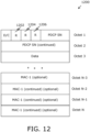
- the specific bit value acts as a flag to signal the network entity or the target communication device that the multipath function is to be enabled.
- An example of the indicator is further described in FIG. 12 .
- the enablement of the multipath function refers to an indication that a specific treatment needs to be provided to the data packets that has the indicator.
- the specific treatment refers to a configuration change or a network capability which allows storage (or maintenance) of the packet information in the header of each data packet of the plurality of data packets received at the network entity (e.g. a base station) and reusage of the packet information to further provide each received packet to the target communication device.
- steps 202 is only illustrative and other alternatives can also be provided where one or more steps are added, one or more steps are removed, or one or more steps are provided in a different sequence without departing from the scope of the claims herein.
- FIG. 3 is a flowchart of a method 300 for executing multipath communication at a network entity, in accordance with an embodiment of the present disclosure.
- the method 300 is executed by a network entity described, for example, in Fig. 6 .
- the method 300 includes steps 302 to 306.
- a first set of data packets is obtained from a source communication device.
- the first set of data packets are obtained via the cellular communication path.
- a header of each data packet of the first set of data packets comprises packet information.
- the packet information is indicative of an association among the first set of data packets.
- an uplink sequence number is mapped to a downlink sequence number for each data packet of the received first set of data packets based on the packet information.
- the uplink sequence number is received in a specified network layer from the source communication device.
- the uplink sequence number is mapped to the downlink sequence number in the specified network layer.
- the specified network layer is at least one of a PDCP layer, a Service Data Adaptation Protocol (SDAP) layer, or another network layer.
- the network entity (such as the source network access node) may be configured to perform mapping of uplink PDCP sequence number with downlink PDCP sequence number in order to address incorrect ordering of data packets and enable the target communication device to compare (or match) data packets received via sidelink communication path with the data packets received via the cellular communication path.
- the network entity or the target network entity to apply the conventional PDCP sequence derivation method for the downlink data packets.
- each received data packet of the first set of data packets that includes the packet information is provided to at least one of a target communication device or a further network entity based on the mapped uplink sequence number to the downlink sequence number.
- the method 300 further includes appending, by the network entity, the uplink sequence number (SN) received from the source communication device in a core network protocol-based header of each received data packet of the first set of data packets.
- the method further includes communicating, by the network entity, each received data packet of the first set of data packets having the core network protocol-based header that includes the appended uplink SN to a core network entity.
- the core network protocol-based header that includes the appended uplink SN is a modified core network protocol-based header that includes the appended uplink SN as an extension in a header structure of the core network protocol-based header.
- the core network protocol-based header is a General Packet Radio Service (GPRS) Tunnelling Protocol User Plane (GTP-U) header.
- GPRS General Packet Radio Service
- GTP-U General Packet Radio Service
- the first set of data packets may not be forwarded to the core network entity, and may directly be communicated from the network entity to the target communication device in the downlink transmission.
- the first set of data packets may not be forwarded to the core network entity, and but may be forwarded to a further network entity, such as the target radio access node, which then forwards the first set of data packets to the target communication device in the downlink transmission.
- the core network protocol-based header may not be used.
- the method 300 further includes setting, by the network entity, the retrieved uplink SN as a downlink SN in each received data packet of the plurality of data packets prior to a downlink transmission of the received data packets of the first set of data packets to the target communication device.
- the method 300 further includes enabling, by the network entity, a multipath function based on an indicator in the header of each data packet of the first set of data packets or in a signalling message transmitted by the source communication device.
- a multipath function based on an indicator in the header of each data packet of the first set of data packets or in a signalling message transmitted by the source communication device.
- An example of the indicator in the header of a data packet is described, for example, in FIG. 12 .
- An example of the signalling message(s) in a session is described, for example, in FIG. 11 .
- the enablement of the multipath function includes storage (or maintenance) of the packet information in each data packet of the first set of data packets received at the network entity and reusing the packet information to further provide each received packet to the target communication device.
- the enablement of the multipath function includes routing each data packet of the first set of data packets having the packet information to a further network entity that reuses the packet information to further provide each received packet to the target communication device
- steps 302, 304, and 306 are only illustrative and other alternatives can also be provided where one or more steps are added, one or more steps are removed, or one or more steps are provided in a different sequence without departing from the scope of the claims herein.
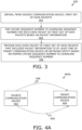
- FIG. 4A is a block diagram that illustrates a network environment of a system 400A for executing multipath communication, in accordance with an embodiment of the present disclosure.
- a network environment of the system 400A that includes a source communication device 402 and a target communication device 404.
- the source communication device 402 and the target communication device 404 may be configured to establish communication with each other via two or more different paths, such as the first path 406 and the second path 408.
- Each of the source communication device 402 and the target communication device 404 may include suitable logic, circuitry, interfaces and/or code that is configured to communicate (send/receive) data via the two or more different paths.
- each of the source communication device 402 and the target communication device 404 is at least one of: a vehicle, an electronic device (e.g. an electronic control unit (ECU), an in-vehicle infotainment (IVI) system, or other in-vehicle device) used in a vehicle, or a portable electronic device (e.g.
- the vehicle may be a non-autonomous, a semi-autonomous, or an autonomous vehicle.
- the multipath communication refers to communication of data via two or more different paths to a common destination device, where each path is different from other paths in use of at least a radio access technology, a communication protocol, a radio link, an interface, or a combination thereof, to communicate data.
- the first path 406 is different from the second path 408 in use of the radio access technology, one or more communication protocols, the radio link, and/or the interface to communicate data.
- the first path 406 may be a cellular communication path (i.e. a cellular network-based communication), whereas the second path 408 may be a sidelink communication path (i.e. a device-to-device communication).
- the cellular network-based communication includes, but is not limited to 5 th generation (5G) or 5G NR (e.g. sub 6 GHz, cmWave, or mmWave communication), Long term evolution (LTE) 4G, 3G, or 2G.
- 5G 5 th generation
- 5G NR e.g. sub 6 GHz, cmWave, or mmWave communication
- LTE Long term evolution
- such cellular network-based communication may be a vehicle-to-network (V2N) communication, which operates, for example, by use of a Uu interface in mobile broadband spectrum.
- V2N vehicle-to-network
- the Uu interface refers to a radio interface between a communication device and a radio access network.
- the first path 406 uses a cellular network having different radio access technology, communication protocols, radio link, and interface (e.g. the Uu interface) to communicate data
- the second path 408 uses a device-to-device communication independent of a cellular network.
- the device-to-device communication improves spectrum utilisation and capacity and enhance network performance and throughput.
- Examples of the device-to-device communication include, but is not limited to IEEE 802.11p, Wireless Fidelity (Wi-Fi), Wi-Fi Direct, LTE Direct, an inband device-to-device communication, an outband device-to-device communication, or a proximity-based services (ProSe) based device-to-device communication.
- the device-to-device communication may be performed in cellular system, which is known as inband device-to-device communication or may occur in unlicensed spectrum, which is known as outband device-to-device communication.
- the device-to-device communication is a direct communication between the source communication device 402 and the target communication device 404, which is potentially implemented via different interfaces (e.g. a PC5 interface, a PC3 interface, or other wireless local area network (WLAN)-based interface).
- WLAN wireless local area network
- the first path 406 may employ IEEE 802.11p, whereas the second path 408 may employ a 5G-V2X communication or an LTE-V2X (via PC5) communication.
- the first path 406 and the second path 408 may employ different device-to-device communication, such as the first path 406 may employ LTE PC5, whereas the second path 408 may employ NR PC5.
- the first path 406 may employ a Wi-Fi based communication
- the second path 408 may employ a PC5 interface-based device-to-device communication.
- a user of the source communication device 402 may want to communicate data with the target communication device 404.
- the source communication device 402 is configured to select a duplication mode or a split mode to communicate a plurality of data packets to the target communication device 404 via two or more different paths.
- the selection of the duplication mode or the split mode occurs before a start of a data session or during a data session.
- the duplication mode and the split mode is described in details, for example, in FIG. 4B and FIG. 4C respectively.
- the source communication device 402 is further configured to provide, to the target communication device 404, a first set of data packets from the plurality of data packets via the first path 406 and a second set of data packets from the plurality of data packets via the second path 408.
- the plurality of data packets includes different data packets having different payload (e.g. in a case where the split mode is selected) or duplicate data packets having a copy of same payload (e.g. in a case where the duplicate mode is selected).
- a header of each data packet includes packet information indicative of an association among the plurality of data packets.
- the source communication device 402 is configured to provide the second set of data packets to the target communication device 404 via the second path 408 in a multi-hop process. For example, even if the target communication device 404 moves beyond a specified device-to-device communication range from the source communication device 402, the first set of data packets may traverse through multiple communication devices in device-to-device communication to finally arrive at the destination device, such as the target communication device 404.
- the source communication device 102 is "A" and the target communication device is "D”.
- "B" and “C” are intermediate communication devices. "B” may be in device-to-device communication range from “A” and "C” but not "D".
- “C” may be in device-to-device communication range from “B” and “D” but not “C”.
- "A” can provide the second set of data packets to “D” in the following manner: A to B to C to D, whereas the "D” due to the large coverage area of the cellular communication, may obtain the first set of data packets via the cellular communication path in a downlink transmission.
- the target communication device 404 is configured to obtain, from the source communication device 402 , the plurality of data packets via the two or more different paths.
- the header of each data packet of the plurality of data packets includes packet information.
- the packet information is indicative of an association among the plurality of data packets.
- the packet information in each data packet at the source communication device 402 is the same as the packet information in each data packet at the target communication device 404 irrespective of different radio access technologies, communication protocols, or radio links used in the two or more different paths.
- the plurality of data packets includes different data packets having different payload or duplicate data packets having a copy of same payload.
- the target communication device 404 is further configured to identify the first set of data packets from the plurality of data packets received via the first path 406 and the second set of data packets from the plurality of data packets received via the second path 408 based on the packet information.
- FIG. 4B is a block diagram that illustrates data communication via a duplication mode, in accordance with an embodiment of the present disclosure.
- FIG. 4B is described in conjunction with elements from FIG. 4A .
- an exemplary scenario 400B to depict data communication in a duplication mode.
- the source communication device 402 the target communication device 404, the first path 406, the second path 408, a first set of data packets 410a, 412a, and 414a, and a second set of data packets 410b, 412b, and 414b.
- the two modes are referred to as a duplication mode and a split mode.
- the duplication mode enables redundancy of radio links that increases reliability of data communication.
- duplicate data packets having a copy of same payload are communicated via at least two different paths to ensure that all data packets reach a common destination, such as the target communication device 404.
- the split mode different data packets having different payload are provided concurrently to the common destination, such as the target communication device 404 , via at least two different paths to increase throughput and reduce latency. In other words, some data packets out of a plurality of data packets are communicated via one path whereas some other data packets are concurrently communicated via another path to increase throughput and reduce latency.
- the source communication device 402 is configured to select the duplication mode to communicate the plurality of data packets to the target communication device 404 via the two or more different paths.
- the selection of the duplication mode occurs before a start of a data session, i.e. before initiation of transmission of data packets or during the data session.
- the source communication device 402 is configured to provide the first set of data packets 410a, 412a, and 414a via the first path 406.
- the source communication device 402 is further configured to provide, to the target communication device 404 , the second set of data packets 410b, 412b, and 414b via the second path 408 as duplicate data packets based on the selection of the duplication mode.
- the target communication device 404 is configured to filter the duplicate data packets from the plurality of data packets received at the target communication device 404 based on the packet information.
- the redundant data packets in the first set of data packets 410a, 412a, and 414a and the second set of data packets 410b, 412b, and 414b that are potentially obtained by the target communication device 404 are filtered out.
- Such multipath communication via the duplication mode is advantageous to achieve better reliability than communication via a single path.
- FIG. 4C is a block diagram that illustrates data communication via a split mode, in accordance with an embodiment of the present disclosure.
- FIG. 4C is described in conjunction with elements from FIG. 4A and FIG. 4B .
- an exemplary scenario 400C to depict data communication in a split mode.
- the plurality of data packets is split into a first set of data packets 416, 420, and 424 that are communicated via the first path 406 and a second set of data packets 418, 422, and 426 that are communicated via the second path 408.
- the control circuitry 428 is communicatively coupled to various components of the source communication device 402 via an in-vehicle network, such as in-vehicle data buses, such as a vehicle area network (VAN) and/or a controller area network (CAN) bus.
- VAN vehicle area network
- CAN controller area network
- the control circuitry 428 is configured to provide a plurality of data packets to the target communication device 404 via two or more different paths.
- the control circuitry 428 is configured to execute instructions stored in the memory 436.
- Examples of the control circuitry 428 may include, but is not limited to a microprocessor, a microcontroller, a complex instruction set computing (CISC) processor, an application-specific integrated circuit (ASIC) processor, a reduced instruction set (RISC) processor, a very long instruction word (VLIW) processor, a central processing unit (CPU), a state machine, a data processing unit, and other processors or circuits.
- the control circuitry 428 may refer to one or more individual processors, processing devices, a processing unit that is part of a machine.
- the transceiver 430 may include suitable logic, circuitry, and/or interfaces that may be configured to communicate with one or more external devices, such as a radio access network node (e.g. a base station) or a target communication device 404 via two or more different paths.
- a radio access network node e.g. a base station
- Examples of the transceiver 430 may include, but is not limited to, an antenna, a telematics unit, a radio frequency (RF) transceiver, one or more amplifiers, one or more oscillators, a digital signal processor, a coder-decoder (CODEC) chipset, and/or a subscriber identity module (SIM) card.
- the transceiver 430 may wirelessly communicate by use of various communication protocols of the first path 406 and the second path 408 (as described in FIG. 4A ).
- the one or more interfaces 432 refers to a sidelink interface and a cellular interface.
- the sidelink interface include, but is not limited to a PC5 interface, a PC3 interface, or another interface that allows device-to-device communication.
- the cellular interface include, but is not limited to Uu interface.
- a unified interface may be provided that allows communication to two or more paths via a same unified interface.
- the I/O device 434 refers to input and output devices that can receive input from a user and provide output to the user.
- the I/O device 434 may be communicatively coupled to the control circuitry 428.
- Examples of input devices may include, but are not limited to, a touch screen, such as a touch screen of a display device, a microphone, a motion sensor, a light sensor, a dedicated hardware input unit (such as a push button), and a docking station.
- Examples of output devices include a display device and a speaker.
- Examples of the display device include, but is not limited to a vehicle display (such as a head-up display (HUD), an augmented reality system (AR-HUD), a display screen of a driver information console (DIC), an infotainment unit or head unit (HU)), a non-vehicle display, such as a smart-glass display, a display screen of a portable device, or other display screen.
- a vehicle display such as a head-up display (HUD), an augmented reality system (AR-HUD), a display screen of a driver information console (DIC), an infotainment unit or head unit (HU)
- a non-vehicle display such as a smart-glass display, a display screen of a portable device, or other display screen.
- the memory 436 may include suitable logic, circuitry, and/or interfaces that may be configured to store machine code and/or instructions with at least one code section executable by the control circuitry 428.
- the memory 436 may store the plurality of data packets for processing and presentation to an application layer of the source communication device 402 .
- Examples of implementation of the memory 436 may include, but are not limited to, Electrically Erasable Programmable Read-Only Memory (EEPROM), Random Access Memory (RAM), Read Only Memory (ROM), Hard Disk Drive (HDD), Flash memory, a Secure Digital (SD) card, Solid-State Drive (SSD), and/or CPU cache memory.
- the memory 436 may store an operating system and/or other program products to operate the source communication device 402.
- a computer readable storage medium for providing a non-transient memory may include, but is not limited to, an electronic storage device, a magnetic storage device, an optical storage device, an electromagnetic storage device, a semiconductor storage device, or any suitable combination of the foregoing.
- FIG. 4E is a block diagram that illustrates various exemplary components of a target communication device, in accordance with an embodiment of the present disclosure.
- FIG. 4E is described in conjunction with elements from FIGs. 1 to 3 , and 4A to 4D .
- the target communication device 404 includes a control circuitry 438, a transceiver 440, one or more interfaces 442, an input/output (I/O) device 444, and a memory 446.
- the control circuitry 438 may be communicatively coupled to the transceiver 440, the one or more interfaces 442, the I/O device 444, and the memory 446.
- the control circuitry 438 is communicatively coupled to various components of the target communication device 404 via an in-vehicle network, such as in-vehicle data buses, such as a vehicle area network (VAN) and/or a controller area network (CAN) bus.
- VAN vehicle area network
- CAN controller area network
- the control circuitry 438 is configured to obtain a plurality of data packets via two or more different paths.
- the control circuitry 428 is configured to execute instructions stored in the memory 436. Examples of the control circuitry 438 is similar to that of the control circuitry 428 ( FIG. 4D ).
- examples of implementation of the transceiver 440, the one or more interfaces 442, the I/O device 444, and the memory 446 is similar to that of the transceiver 430, the one or more interfaces 432, the I/O device 434, and the memory 436, respectively of FIG. 4D .
- FIG. 5 is a block diagram that illustrates a network environment of a system 500 with various nodes of a cellular network, in accordance with an embodiment of the present disclosure.
- FIG. 5 is described in conjunction with elements from FIGs. 1 to 3 , and 4A to 4E .
- the system 500 that includes the source communication device 402 , the target communication device 404 , and one or more network entities of a cellular network 502 , such as a source radio access network (RAN) node 504 , a core network entity 506, a target RAN node 508.
- RAN radio access network
- Each of the source RAN node 504 and the target RAN node 508 refers to a radio base station, such as a NodeB, an evolved Node B (eNB), Next Generation Node B (gNB), a base transceiver station, an access point base station, a base station router, or any other network entity capable of communicating with a wireless device (e.g. the source communication device 402 or the target communication device 404).
- the cellular network 502 covers a geographical area which is divided into cell areas, where one or more cell areas are served by the source RAN node 504 and the target RAN node 508.
- the core network entity 506 is a part of the cellular network 502 that connects the different nodes (or parts) of the access network (i.e. RAN).
- the core network entity 506 includes, for example, serving gateway (S-GW), packet data network (PDN) gateway (PDN GW), mobility management entity, Home Subscriber Server (HSS) as evolved packet core (EPC).
- S-GW serving gateway
- PDN packet data network gateway
- HSS Home Subscriber Server
- network entities are referred to as "functions” and are usually not referred to as "nodes”.
- the functions of the 4G S-GW and PDN-GW is merged into a single entity, called user plane function (UPF).
- UPF user plane function
- the 4G MME is split into two individual functions, such as access management function (AMF) and session management function (SMF).
- AMF access management function
- SMF session management function
- a network entity may cover both access node entities and core network entities (e.g. network nodes or functions).
- the source communication device 402 is configured to provide a first set of data packets from a plurality of data packets to the target communication device 404 via a cellular communication path 510.
- the first set of data packets are first communicated to a network entity (such as the source RAN node 504 ) in an uplink transmission 512. Thereafter, the first set of data packets may be further communicated to the target communication device 404 or a further network entity, such as the core network entity 506 and the target RAN node 508, to provide to the target communication device 404 in a downlink transmission 514.
- the source communication device 402 is further configured to communicate a second set of data packets from the plurality of data packets to the target communication device 404 via a sidelink communication path 516.
- a header of each data packet includes packet information that is indicative of an association among the plurality of data packets.
- the network entity such as the source RAN node 504 , is configured to obtain, from the source communication device 402, the first set of data packets.
- the header of each data packet of the first set of data packets comprises packet information.
- the network (such as the source RAN node 504 ) is configured to enable a multipath function based on an indicator in the header of each data packet of the first set of data packets or in a signalling message transmitted by the source communication device 402.
- the multipath function refers to a network capability which allows storage (or maintenance) of the packet information in the header of each data packet of the first set of data packets received at the network entity (such as the source RAN node 504) and reusage of the packet information to further provide each received packet to the target communication device 404.
- the multipath function refers to a network capability which allows routing of each data packet of the first set of data packets having the packet information to a further network entity that reuses the packet information to further provide each received packet to the target communication device 404 via the network entity (such as the source RAN node 504), or another network entity (such as the target RAN node 508).
- the network entity such as the source RAN node 504 , is further configured to map an uplink sequence number (e.g. uplink PDCP sequence number) to a downlink sequence number (e.g. downlink PDCP sequence number) for each data packet of the received first set of data packets based on the packet information.
- the network entity such as the source RAN node 504, is further configured to provide each received data packet of the first set of data packets that includes the packet information to at least one of the target communication device 404 or a further network entity (such as the core network entity 506 or the target RAN node 508) based on the mapped uplink sequence number to the downlink sequence number.
- the target communication device 404 is configured to obtain the plurality of data packets via the cellular communication path 510 and the sidelink communication path 516.
- the plurality of data packets includes different data packets having different payload or duplicate data packets having a copy of same payload.
- the target communication device 404 is configured to identify the first set of data packets from the plurality of data packets received via the cellular communication path 510 and the second set of data packets from the plurality of data packets received via the sidelink communication path 516 based on the packet information.
- FIG. 6 is a block diagram that illustrates various exemplary components of a network entity, in accordance with an embodiment of the present disclosure.
- FIG. 6 is described in conjunction with elements from FIGs. 4A to 4E , and 5 .
- the network entity 600 corresponds to one of the network entities of the cellular network 502 ( FIG. 5 ).
- the network entity 600 covers both access network entities (e.g. RAN node) and core network entities (e.g. nodes or functions).
- the network entity 600 includes an entity control circuitry 602 , a transceiver 604 , and a memory 606.
- the entity control circuitry 602 is communicatively coupled to the transceiver 604, and the memory 606.
- the entity control circuitry 602 is configured to obtain a first set of data packets from the source communication device 402 , where a header of each data packet of the first set of data packets comprises packet information. The packet information is indicative of an association among the first set of data packets.
- Examples of the entity control circuitry 602 is similar to that of the control circuitry 428 ( FIG. 4D ).
- the entity control circuit, or simply control circuit, in this and in the following embodiments may be a general-purpose processor running a dedicated software or a dedicated hardware circuitry.
- examples of implementation of the transceiver 604 and the memory 606 is similar to that of the transceiver 430 and the memory 436, respectively of FIG. 4D .
- the entity control circuitry 602 is configured to append the uplink sequence number (SN) received from the source communication device 402 in a core network protocol-based header of each received data packet of the first set of data packets.
- the entity control circuitry 602 is further configured to communicate each received data packet of the first set of data packets having the core network protocol-based header that includes the appended uplink SN to the core network entity 506.
- the core network protocol-based header that includes the appended uplink SN is a modified core network protocol-based header that includes the appended uplink SN as an extension in a header structure of the core network protocol-based header.
- the core network protocol-based header is a GTP-U header.
- the entity control circuitry 602 is further configured to set the retrieved uplink SN as a downlink SN in each received data packet of the plurality of data packets prior to a downlink transmission of the received data packets of the first set of data packets to the target communication device 404.
- the entity control circuitry 602 is configured to enable the multipath function based on an indicator in the header of each data packet of the first set of data packets or in a signalling message transmitted by the source communication device 402.
- the enablement of the multipath function includes storage of the packet information in each data packet of the first set of data packets received at the network entity 600 and reusing the packet information to further provide each received packet to the target communication device 404.
- the enablement of the multipath function further includes routing of each data packet of the first set of data packets having the packet information to a further network entity (such as the core network entity 506 ) that reuses the packet information to further provide each received packet to the target communication device 404 via the network entity 600, or another network entity.
- FIG. 7 illustrates an exemplary scenario 700 to execute multipath communication with network layers, in accordance with an embodiment of the present disclosure.
- FIG. 7 is described in conjunction with elements from FIGs. 4A to 4E , 5, and 6 .
- a first plurality of network layers 702A i.e. a user plane protocol stack
- a second plurality of network layers 702B i.e. a corresponding user plane protocol stack
- Each of the first plurality of network layers 702A and the second plurality of network layers 702B includes a physical (PHY) layer, a media access control (MAC) layer, a radio link control (RLC) layer, a PDCP layer, a convergence layer, and an application layer.
- PHY physical
- MAC media access control
- RLC radio link control
- PDCP packet data convergence protocol
- SDAP service data adaptation protocol
- Each network layer may also be referred to as a protocol layer of the user plane protocol stack.
- the method to execute multipath communication at the source communication device 402, the network entity 600, and the target communication device 404 is potentially implementable at different network layers.
- a specific network layer or protocol layer
- different approaches or solutions may be used to execute the multipath communication.
- the different approaches include a communication device-based approach and a network-based approach.
- the source communication device 402 is configured to generate a packet identifier (e.g. for a duplicated or a split packet) or a sequence number.
- the packet identifier (or the sequence number) is appended to the header (e.g. in the application layer or the convergence layer (such as a V2X layer in case of a vehicle)) of each data packet of a plurality of data packet that are to be provided to the target communication device 404.
- the packet identifier (or the sequence number) is introduced in a header of each data packet at the communication layer, the application layer, or at the V2X layer (in case of vehicles) to reduce the impact on existing protocol layers of the user plane protocol stack.
- a sequence number is assigned to each data packet at a transmitting end (i.e. the source communication device 402 ) in the PDCP layer before each data packet passes to a next layer (i.e. the RLC layer).
- This sequence number is used at the PDCP layer at the receiving end (i.e. the target communication device 404) to align data packets in a sequential order.
- there is a problem in transmission of data packets via different paths e.g. the cellular communication path 510 and the sidelink communication path 516) that employs different interfaces (e.g. a NR Uu interface and the NR PC5 interface).
- the problem is that the target communication device 404 may not able to compare (or match) the data packets received via a cellular interface (i.e. the Uu interface) with data packets received from a sidelink interface (i.e. the PC5 interface).
- the downlink and the uplink sequence numbers of the data packets may be different or the packets may become disarranged (i.e. incorrectly ordered).
- the comparison of data packets communicated via the sidelink interface with the data packets sent via the cellular interface is not feasible.
- the packet information i.e.
- the packet identifier for a split data packet or a duplicate data packet or a dedicated sequence number is appended (or assigned) to the header of each data packet in upper layers (i.e. the application layer or the convergence layer (such as a V2X layer in case of a vehicle)).
- packet information is additional control information (e.g. additional packet identifier or additional sequence number other than the usual PDCP sequence number) that is retained in the header of each data packet of the plurality of data packets irrespective of the path (e.g. the cellular communication path 510 and the sidelink communication path 516) or different network nodes that the data packets traverses.
- the corresponding layer (e.g., the application layer or the convergence layer, and the like) at the target communication device 404 is utilized to compare and identify the packets based on the packet information (e.g. the additional packet identifier or the additional sequence number) in each data packet.
- the communication device-based approach does not have any impact on the network.
- the source communication device 402 is configured to generate a duplication identifier (ID), which is set for the duplicate data packets.
- ID is stored (i.e. maintained) in the header of each data packet irrespective of the different radio access technologies, communication protocols, or radio links used in the two or more different paths traversed by the data packets.
- the convergence layer or the V2X layer (in case of V2V communication) may be used to generate the duplication ID at the source communication device 402 and to perform reordering or filtering of the received data packets at the corresponding convergence layer at the target communication device 404.
- duplication ID allows unique identification of the duplicated data packets at the target communication device 404 regardless of the paths or intermediate protocols and network nodes followed by the data packets.
- a packet ID may be set for the split data packets that remains in the data packet throughout the communication process for unique identification of the split data packets at the target communication device 404 .
- the network is enabled to maintain the packet information (e.g. the packet identifier or the sequence number) that is set at the source communication device 402 at a specific network layer (e.g. the PDCP, SDAP, or another network layer) across the end-to-end network.
- the network entity 600 e.g. a base station
- the network-based approach has a network impact as it involves signalling to the network to maintain the packet information in header of each data packet throughout the end-to-end network.
- FIG. 8 illustrates an exemplary scenario 800 for execution of multipath communication using different radio access technologies, in accordance with an embodiment of the present disclosure.
- FIG. 8 is described in conjunction with elements from FIGs. 1 to 3 , 4A to 4E , 5, 6 , and 7 .
- an application layer 802A at the source communication device 402 and a corresponding application layer 802B at the target communication device 404.
- the control circuitry 428 of the source communication device 402 and the control circuitry 438 of the target communication device 404 is shown.
- the control circuitry 428 of the source communication device 402 is configured to provide, to the target communication device 404 , a first set of data packets from a plurality of data packets via a first path and a second set of data packets from the plurality of data packets via a second path.
- the first path uses a first radio access technology (RAT-1) and the second path uses a second radio access technology (RAT-2) that is different than the RAT-1.
- the first path and the second path correspond to different device-to-device communication that employ different radio access technologies (e.g. NR PC5 interface and LTE PC5 interface as shown).
- the control circuitry 428 is configured to set a sequence number (i.e. a dedicated sequence number) for each data packet at the application layer 802A , irrespective of the radio access technologies (i.e. RAT-1 or RAT-2) used for data communication.
- the RAT may be for example, LTE, 5G, and the like.
- the corresponding application layer 802B of the target communication device 404 is used to check the sequence number of each data packet obtained from the source communication device 402 .
- the control circuitry 438 of the target communication device 404 is configured to reorder the plurality of data packets obtained in the first path and the second path (i.e.
- the split mode at the corresponding application layer 802B in accordance with the sequence number associated with each of the plurality of data packets.
- the convergence layer instead of the application layer 802A , the convergence layer, the V2X layer, or any other network layer outside the access stratum (AS) may be used to set the sequence number.
- the same network layer that is used to set the sequence number is then used at the target communication device 404 to check the sequence number and accordingly perform the reordering.
- the control circuitry 428 is configured to set a sequence number (i.e. additional dedicated sequence number) for each data packet at the application layer 802A , irrespective of the radio access technologies (i.e. RAT-1 or RAT-2) used for data communication.
- a duplicate ID is potentially assigned to duplicate data packets (e.g. the second set of data packets may have same payload as the first set of data packets) at the application layer 802A (or the convergence layer, or V2x layer in case of a vehicle).
- the control circuitry 438 of the target communication device 404 is configured to identify the duplicate data packets based on the duplication ID even if the plurality of data packets is obtained from the source communication device 402 via the different radio access technologies (i.e. via NR PC5 interface and LTE PC5 interface).
- the control circuitry 438 is configured to filter the duplicate data packets from the plurality of data packets received at the target communication device at the corresponding application layer 802B (or convergence layer, or the V2x layer) based on the packet information (e.g. the duplication ID and the dedicated sequence number).
- FIG. 9 illustrates an exemplary scenario 900 for execution of multipath communication with packets duplication and splitting at a PDCP layer, in accordance with an embodiment of the present disclosure.
- FIG. 9 is described in conjunction with elements from FIGs. 4A to 4E , 5 , 6 , 7 , and 8 .
- a SDAP layer 902A there is shown a SDAP layer 902A , a PDCP layer 904B , an RLC layer 906A , a MAC layer 908A of a user plane protocol stack in the source communication device 402 associated with a cellular interface (e.g. the Uu interface).
- a cellular interface e.g. the Uu interface
- the corresponding network layers such as a SDAP layer 902B, a PDCP layer 904B, a RLC layer 906B, and a MAC layer 908B that are associated with corresponding Uu interface is shown in the target communication device 404.
- network layers associated with the sidelink communication such as sidelink (SL) RLC 910A and SL MAC 912A
- SL RLC 910B and SL MAC 912B are further shown in the source communication device 402 and the target communication device 404 (e.g. SL RLC 910B and SL MAC 912B).
- control circuitry 428 of the source communication device 402 and the control circuitry 438 of the target communication device 404 There is further shown the control circuitry 428 of the source communication device 402 and the control circuitry 438 of the target communication device 404.
- the data packets duplication or splitting is described with respect to the PDCP layer 904A instead of upper layers (such as the application layer, the convergence layer, or the V2X layer in case of a vehicle).
- the data packets duplication or splitting may be implemented at different network layers, such as the SDAP layer 902A .
- the data packets with same PDCP headers i.e. same PDCP SN
- the sidelink communication path e.g. PC5 interface
- the uplink PDCP SN is same as that of the sidelink PDCP SN. However, the uplink PDCP SN still needs to be same as that of the downlink PDCP SN for efficient and error free transmission of data from the source communication device 402 to the target communication device 404 in the multipath communication. Typically, in conventional systems, the PDCP SN of a given data packet in the uplink transmission may not be same with the PDCP SN of the same given packet in the downlink transmission.
- the source RAN node 504 is configured to map an uplink PDCP SN received from the source communication device 402 with a downlink PDCP SN for each data packet of the first set of data packets received at the source RAN node 504.
- the mapping of the uplink PDCP SN with the downlink PDCP SN is done in order to address incorrect ordering issues and allow the target communication device 404 to compare (or match) the data packets obtained via the cellular communication path 510 with the data packets obtained via the sidelink communication path 516. It will be appreciated that the mapping between the uplink PDCP SN with the corresponding downlink PDCP SN requires cooperation between the RAN (such as the source RAN node 504 and the target RAN node 508) and the core network entity 506 of the cellular network 502 for comparison of the data packets.
- the source RAN node 504 is further configured to append the uplink PDCP SN obtained from the source communication device 402 in a core network protocol-based header (e.g.
- the source RAN node 504 appends the uplink PDCP SN in the GTP-U header of the data packets that are sent via, for example, N3 interface, for a specific service flow (QFI).
- QFI specific service flow
- the GTP-U is responsible for carrying the data within the GPRS core network as well as between the RANs (such as the source RAN node 504 and the target RAN node 508) and the core network entity 506.
- the transported data in the form of data packets may be in several formats such as Internet Protocol version 4 (IPv4) format, Internet Protocol version 6 (IPv6) format, point-to-point protocol (PPP) format and the like.
- IPv4 Internet Protocol version 4
- IPv6 Internet Protocol version 6
- PPP point-to-point protocol
- the source RAN node 504 communicates each received data packet of the first set of data packets having the GTP-U header that includes the appended uplink PDCP SN to the core network entity 506.
- the GTP-U header that includes the appended uplink PDCP SN is a modified GTP-U header that includes the appended uplink PDCP SN as an extension in a header structure of the GTP-U header.
- An example of the GTP-U header is described in FIG. 10 .
- the uplink PDCP SN is forwarded via the core network entity 506 entities of the first path 406. Further, the user plane function (UPF) node maintains the PDCP SN in the GTP-U header that are transmitted over the N3 interface or an N9 interface.
- the GTP-U header is thus a modified GTP-U header that includes at least the packet information, for example, the uplink PDCP SN.
- FIG. 10 illustrates an exemplary structure of a GPRS Tunnelling Protocol User Plane (GTP-U) header 1000, in accordance with an embodiment of the present disclosure.
- GTP-U GPRS Tunnelling Protocol User Plane
- FIG. 10 is described in conjunction with elements from FIGs. 1 to 3 , 4A to 4E , and 5 to 9 .
- FIG. 10 there is shown an example of a core network protocol-based header, such as the GTP-U header 1000.
- the GTP-U header 1000 includes various fields in accordance to the 3GPP specification, such as "Message type” that is reserved for a type of data present in a data packet.
- the message type may be text, an image, an audio, or a video.
- the GTP-U header 1000 may further includes fields, such as length (i.e. measured in terms of number of bits) of the data packet, "Tunnel endpoint identifier", "Sequence number” and the like.
- the GTP-U header 1000 further includes a new extension header type field 1002.
- the new extension header type field 1002 is used to include information, such as duplication mode or the split mode associated with the data packets that are potentially sent via N3 interface between a RAN node (such as the source RAN node 504 ) and a user plane function (UPF) or via N9 interface between two two UPFs (e.g. intra-Public Land Mobile Network (PLMN) interface or inter-PLMN interface).
- the new extension header type field 1002 is enhanced or extended) to include, for instance, uplink PDCP SN and the Quality of service Flow Identifier (QFI).
- the uplink PDCP SN is appended in a 5G encapsulation header, in a 5G cellular network on N3 (and/or N9) interfaces to reduce changes to the header of a data packet across the e2e network.
- Activation of multipath function there are two options for the activation of the multipath function, for example, in the network-based approach (or solution).
- the first option is activation on a session level and the second option is activation on per data packet basis.
- a radio access network node e.g. a base station, such as a gNB
- UPF user plane function
- PDU protocol data unit
- the multipath function is activated based on an indicator in the header of each data packet of the first set of data packets, to provide a specific treatment to uplink and downlink data packets by the various network nodes and interfaces on per data packet basis.
- the activation of the multipath function based on the indicator in the header of each data packet is described in details, for example, in FIG. 12 .
- FIG. 11 is a sequence diagram 1100 that illustrates a portion of a procedure of protocol data unit (PDU) session establishment, in accordance with an embodiment of the present disclosure.
- FIG. 11 is described in conjunction with elements from FIGs. 1, 2 , 3 , 4A to 4E , 5 , 6 , 7 , 8 , 9 , and 10 .
- a user equipment (UE) 1102 a radio access network (R)AN 1104, an access and mobility management function (AMF) 1106, a user plane function (UPF) 1108, a session management function (SMF) 1110, a policy control function (PCF) 1112, a unified data management (UDM) 1114, and a data network 1116.
- the UE 1102 corresponds to the source communication device 402 .
- the RAN 1104 corresponds to the source RAN node 504 ( FIG. 5 ).
- the sequence diagram 1100 depicts a portion of a procedure of PDU session establishment that is compliant to the 3GPP specification.
- some operations in the sequence diagram 1100 that involve SMF 1110 signalling to RAN 1104 and UPF 1108 are potentially enhanced (or extended) to enable the multipath function at one or more network entities based on an indicator in a signalling message transmitted by the source communication device 402 (e.g. by control plane signalling).
- the SMF 1110 signalling to the RAN 1104 e.g. steps 1124 and 1126
- the UPF 1108 e.g. step 1134A
- the SMF 1110 signalling to RAN 1104 is potentially enhanced (or extended) to enable transfer of the sequence number received in a specific network layer (e.g. PDCP SN) in N3 in an uplink data packet, and further enable use of the uplink SN in the specified network layer (e.g. downlink PDCP SN) for the downlink packet.
- a specific network layer e.g. PDCP SN
- the signalling of SMF 1110 to UPF 1108 is potentially extended to enable the UPF 1108 to forward the received data packets that includes the modified core network protocol-based header (e.g. the modified GTP-U header) that includes the appended uplink sequence number to appropriate QFIs in the downlink PDU session.
- the modified core network protocol-based header e.g. the modified GTP-U header
- PDU session establishment request SMF selection by the AMF
- signalling from AMF to SMF i.e. in the form of a Nsmf_PDUSession_CreateSMContext Request
- retrieval of session management subscription data by SMF if not available
- signalling from SMF to AMF i.e. in the form of a Nsmf_PDUSession_CreateSMContext Response
- the like e.g. as specified in 3GPP-23.502.
- the SMF 1110 initiates a session management policy association modification between the SMF 1110 and the PCF 1112.
- a N4 session establishment/modification request is communicated from the SMF 1110 to the UPF 1108.
- a N4 session establishment or modification response is communicated from the UPF 1108 to the SMF 1110.
- a Namf_communication_N1N2message transfer is executed from the SMF 1110 to the AMF 1106. In a case where N2 session management (SM) information is not included in the step 1124, then the following step 1130 to 1134B and step 1136 are potentially omitted.
- SM N2 session management
- the Namf_communication_N1N2 message transfer is enhanced and extended to enable transfer of the sequence number received in a specific network layer (e.g. PDCP SN) in N3 in an uplink data packet.
- a N2 PDU session request is communicated from AMF 1106 to RAN 1104.
- the N2 PDU session request is also enhanced and extended to enable use of the uplink SN in the specified network layer (e.g. downlink PDCP SN) for the downlink packet (in the downlink transmission).
- the N2 PDU session request is accepted.
- a N2 PDU session request acknowledgement is communication from the RAN 1104 to the AMF 1106.
- Nsmf_PDUSession_updateSMContext request is communicated from the AMF 1106 to the SMF 1110.
- a N4 session modification request is communicated from the SMF 1110 to the UPF 1108.
- the signalling of the SMF 1110 to UPF 1108 is potentially enhanced and extended to enable the UPF 1108 to forward the received data packets that includes the modified core network protocol-based header (e.g. the modified GTP-U header) that includes the appended uplink sequence number to appropriate QFIs in the downlink PDU session.
- the N4 session modification request is used to enable the UPF 1108 to forward the received data packets that includes the modified core network protocol-based header (e.g.
- a N4 session modification response is received by the SMF 1110.
- a Nsmf_PDUSession_updateSMContext response is communicated from the SMF 1110 to the AMF 1106.
- a Nsmf_PDUSession_SMContext_status_notify service is executed from the SMF 1110 to the AMF 1106.
- IPv4 has an identifier (ID) (i.e. IP ID) that is enabled for packets fragmentation, but such IP ID is not included in IPv6.
- ID i.e. IP ID
- QoS Flow Identifier QFI
- QFI QoS Flow ID
- a QoS Flow ID is used to identify a QoS Flow in a 5G (NR) capable device.
- a user plane traffic with the same QFI within a PDU session receives the same traffic forwarding treatment (e.g. scheduling, admission threshold, and the like).
- the QFI is carried in an encapsulation header on N3 (and N9) interface i.e. without any changes to the packet header across the e2e network.
- This QFI is used for all PDU session types.
- the QFI is unique within a PDU Session.
- the QFI may be dynamically assigned or may be equal to the 5QI (i.e. 5G QoS characteristics).
- 5QI i.e. 5G QoS characteristics
- core network packet identifier in N3 includes in the user plane, an increasing SN for transport (T)-PDUs is transmitted via GTP-U tunnels (GTP-U header), when transmission order of data packets must be preserved.
- This field is an optional field in G-PDUs that consists of a GTP-U header plus a T-PDU within the GPRS backbone network.
- the focus is on the one part of N3 transmission (i.e. from RAN to UPF, or from UPF to RAN) and there is no direct link/correlation with RAN packet IDs.
- the various steps e.g. steps 1122A to 1128
- step 1134A of the sequence diagram 1100 are enhanced and extended to enable the multipath function, and solve the issues associated with the conventional methods and systems as described above.
- FIG. 12 illustrates an exemplary indicator in a header of a data packet, in accordance with an embodiment of the present disclosure.
- FIG. 12 is described in conjunction with elements from FIGs. 1, 2 , 3 , 4A to 4E , and 5 to 11 .
- a PDCP header structure 1200 there is shown a PDCP header structure 1200.
- the PDCP header structure 1200 includes a plurality of fields, such as a plurality of reserve fields 1202, 1204, and 1206, and fields for MAC address of a data packet.
- any one or more reserve fields of the plurality of reserve fields 1202, 1204, and 1206 is potentially used as an indicator (e.g. a flag) in order to enable the RAN mapping of the uplink PDCP SN with the downlink PDCP SN for a data packet.
- the reserve field 1202 may be set to a specific bit value (e.g. bit value "1") from the binary bit values (0 or 1) by the source communication device 402 to signal to the network entity 600 (e.g. the source RAN node 504 ) to activate the multipath function to enable mapping of the uplink PDCP SN with the downlink PDCP SN.
- the source RAN node 504 is configured to map the uplink PDCP SN with the downlink PDCP SN based on the indicator (i.e. a bit value of "1" in the reserve filed 1202 in this example).
- the source communication device 402 is further configured to set the reserve field 1204 in the PDCP header structure 1200 for an uplink data packet as an indication of the selection of the duplication mode at the source communication device 402.
- the target communication device 404 is configured to determine that the plurality of data packets obtained from the source communication device 402 via two or more different paths includes duplicate data packets.
- the use of the plurality of reserve fields 1202, 1204, and 1206 as an indicator allows per packet treatment of the uplink and downlink data packets instead of a pre flow treatment, without the need to modify existing PDCP header to minimize cost of implementation.
- FIG. 13 illustrates an exemplary scenario 1300 to execute vehicle-to-vehicle (V2V) multipath communication, in accordance with an embodiment of the present disclosure.
- FIG. 13 is described in conjunction with elements from FIGs. 1, 2 , 3 , 4A to 4E , and 5 to 12 .
- the exemplary scenario 1300 that includes a source vehicle 1302 and a target vehicle 1304 moving on a road portion 1306.
- the source vehicle 1302 includes an electronic control unit (ECU) 1308 and the target vehicle 1304 includes an ECU 1310.
- ECU electronice control unit
- the target vehicle 1304 includes an ECU 1310.
- the source vehicle 1302 and the target vehicle 1304 correspond to the source communication device 402 and the target communication device 404, respectively ( FIG. 4A ).
- the source base station 1312 and the target base station 1314 correspond to the source RAN node 504 and the target RAN node 508 respectively ( FIG. 5 ).
- the source vehicle 1302 may be within a communication range to establish a D2D communication with each other.
- a user of the source vehicle 1302 may want to communicate data to the target vehicle 1304.
- the ECU 1308 of the source vehicle 1302 is configured to select a duplication mode or a split mode to communicate a plurality of data packets to the target vehicle 1304 via the cellular communication path 1316 and the sidelink communication path 1318.
- the ECU 1308 of the source vehicle 1302 is configured to provide, to the target vehicle 1304, a first set of data packets from the plurality of data packets via the cellular communication path 1316 and a second set of data packets from the plurality of data packets via the sidelink communication path 1318.
- a plurality of V2X packets are communicated through different radio access technologies, radio links, interfaces, or communication protocols to improve the QoS of the communication between two vehicles, so as to increase reliability of V2V communication.
- a header of each data packet includes packet information indicative of an association among the plurality of data packets.
- the first set of data packets traverses through various network entities, such as the source base station 1312, and a neighbouring base station, such as the target base station 1314. In some cases, the first set of data packet may also traverse through a core network entity.
- the source base station 1312 is configured to obtain the first set of data packets from the source vehicle 1302.
- the header of each data packet of the first set of data packets comprises packet information.
- the source base station 1312 is configured to map an uplink sequence number received in a specified network layer (e.g. PDCP layer or other network layer) to a downlink sequence number for each data packet of the received first set of data packets based on the packet information.
- the source base station 1312 is configured to provide each received data packet of the first set of data packets that includes the packet information to the target vehicle 1304 in a case where the target vehicle is within a communication range of the source base station 1312 at the time of communication.
- the source base station 1312 is configured to provide each received data packet of the first set of data packets that includes the packet information to a neighbouring base station, such as the target base station 1314.
- the ECU 1310 of the target vehicle 1304 is configured to identify the first set of data packets received via the cellular communication path 1316 and the second set of data packets received via the sidelink communication path 1318 based on the packet information.
- the packet information in the header of each data packet do not change irrespective of different radio access technologies, communication protocols, or radio links used in the two or more different paths (i.e. the cellular communication path 1316 and the sidelink communication path 1318 in this case)
- the quality-of-service (QoS) of data communication between the source vehicle 1302 and the target vehicle 1304 is improved.
- the plurality of data packets obtained via two or more different paths includes different data packets having different payload (i.e.
- V2V multipath communication between the source vehicle 1302 and the target vehicle 1304 is useful in improvement of road safety by providing an efficient and reliable mechanism to share alerts and other data (such as text, image, audio, or video) concurrently via two or more different paths between the source vehicle 1302 and the target vehicle 1304.
Landscapes
- Engineering & Computer Science (AREA)
- Computer Networks & Wireless Communication (AREA)
- Signal Processing (AREA)
- Computer Security & Cryptography (AREA)
- Mobile Radio Communication Systems (AREA)
Claims (7)
- Verfahren (300) zum Ausführen einer Mehrwegekommunikation bei einer Netzwerkentität (600), wobei das Verfahren umfasst:Erhalten, von einer Quellkommunikationsvorrichtung (402), eines ersten Satzes von Datenpaketen, wobei ein Header jedes Datenpakets des ersten Satzes von Datenpaketen Paketinformationen umfasst, wobei die Paketinformationen eine Verknüpfung unter dem ersten Satz von Datenpaketen anzeigen;Zuordnen einer Uplink-Sequenznummer zu einer Downlink-Sequenznummer für jedes Datenpaket des ersten Satzes von Datenpaketen basierend auf den Paketinformationen; undBereitstellen jedes empfangenen Datenpakets des ersten Satzes von Datenpaketen, das die Paketinformationen einschließt, an mindestens eines von einer Zielkommunikationsvorrichtung (404) oder einer weiteren Netzwerkentität basierend auf der zugeordneten Uplink-Sequenznummer zu der Downlink-Sequenznummer; wobeidie Uplink-Sequenznummer in einer angegebenen Netzwerkschicht von der Quellkommunikationsvorrichtung (402) empfangen wird, und wobei die Uplink-Sequenznummer der Downlink-Sequenznummer in der angegebenen Netzwerkschicht zugeordnet wird, wobei die angegebene Netzwerkschicht mindestens eine von einer Paketdatenkonvergenzprotokollschicht, einer Dienstdatenanpassungsprotokollschicht oder einer anderen Netzwerkschicht ist.
- Verfahren (300) nach Anspruch 1, das ferner umfasst:Anhängen, durch die Netzwerkentität (600), der Uplink-Sequenznummer, die von der Quellkommunikationsvorrichtung (402) empfangen wird, in einen kernnetzwerkprotokollbasierten Header jedes empfangenen Datenpakets des ersten Satzes von Datenpaketen; undKommunizieren, durch die Netzwerkentität (600), jedes empfangenen Datenpakets des ersten Satzes von Datenpaketen, das den kernnetzwerkprotokollbasierten Header, der die angehängte Uplink-Sequenznummer einschließt, aufweist, an eine Kernnetzwerkentität (506), wobei der kernnetzwerkprotokollbasierte Header, der die angehängte Uplink-Sequenznummer einschließt, ein modifizierter kernnetzwerkprotokollbasierter Header, der die angehängte Uplink-Sequenznummer als eine Erweiterung in einer Header-Struktur des kernnetzwerkprotokollbasierten Headers einschließt, ist.
- Verfahren (300) nach Anspruch 2, wobei der kernnetzwerkprotokollbasierte Header ein General Packet Radio Service Tunnelling Protocol User Plane-Header (1000) ist.
- Verfahren (300) nach einem der Ansprüche 1 bis 3, das ferner ein Einstellen, durch die Netzwerkentität (600), der abgerufenen Uplink-Sequenznummer als eine Downlink-Sequenznummer in jedem empfangenen Datenpaket der Vielzahl von Datenpaketen vor einer Downlink-Übertragung (514) der empfangenen Datenpakete des ersten Satzes von Datenpaketen an die Zielkommunikationsvorrichtung (404) umfasst.
- Verfahren (300) nach einem der Ansprüche 1 bis 4, das ferner ein Aktivieren, durch die Netzwerkentität (600), einer Mehrwegefunktion basierend auf einer Anzeige in dem Header jedes Datenpakets des ersten Satzes von Datenpaketen oder in einer Signalisierungsnachricht, die durch die Quellkommunikationsvorrichtung (402) übertragen wird, umfasst, wobei die Aktivierung der Mehrwegefunktion einschließt:- Speichern der Paketinformationen in jedem Datenpaket des ersten Satzes von Datenpaketen, die bei der Netzwerkentität (600) empfangen werden, und Wiederverwenden der Paketinformationen, um jedes empfangene Paket der Zielkommunikationsvorrichtung (404) weiter bereitzustellen; oder- Weiterleiten jedes Datenpakets des ersten Satzes von Datenpaketen, das die Paketinformationen aufweist, an eine weitere Netzwerkentität, die die Paketinformationen wiederverwendet, um jedes empfangene Paket der Zielkommunikationsvorrichtung (404) über die Netzwerkentität (600) oder eine andere Netzwerkentität weiter bereitzustellen.
- Netzwerkentität (600) zum Ausführen einer Mehrwegekommunikation, die umfasst: eine Entitätssteuerschaltung (602), die konfiguriert ist zum:Erhalten, von einer Quellkommunikationsvorrichtung (402), eines ersten Satzes von Datenpaketen, wobei ein Header jedes Datenpakets des ersten Satzes von Datenpaketen Paketinformationen umfasst, wobei die Paketinformationen eine Verknüpfung unter dem ersten Satz von Datenpaketen anzeigen;Zuordnen einer Uplink-Sequenznummer zu einer Downlink-Sequenznummer für jedes Datenpaket des ersten Satzes von Datenpaketen basierend auf den Paketinformationen; undBereitstellen jedes empfangenen Datenpakets des ersten Satzes von Datenpaketen, das die Paketinformationen einschließt, an mindestens eines von einer Zielkommunikationsvorrichtung (404) oder einer weiteren Netzwerkentität basierend auf der zugeordneten Uplink-Sequenznummer zu der Downlink-Sequenznummer;wobeidie Uplink-Sequenznummer in einer angegebenen Netzwerkschicht von der Quellkommunikationsvorrichtung (402) empfangen wird, und wobei die Uplink-Sequenznummer der Downlink-Sequenznummer in der angegebenen Netzwerkschicht zugeordnet wird, wobei die angegebene Netzwerkschicht mindestens eine von einer Paketdatenkonvergenzprotokollschicht, einer Dienstdatenanpassungsprotokollschicht oder einer anderen Netzwerkschicht ist.
- Computerprogrammprodukt, das ein nicht flüchtiges, computerlesbares Speichermedium, auf dem computerlesbare Anweisungen gespeichert sind, umfasst, wobei die computerlesbaren Anweisungen durch eine computergestützte Vorrichtung, die Verarbeitungshardware umfasst, ausführbar sind, um ein Verfahren nach einem der Ansprüche 1 bis 5 auszuführen.
Applications Claiming Priority (1)
| Application Number | Priority Date | Filing Date | Title |
|---|---|---|---|
| PCT/EP2019/080335 WO2021089136A1 (en) | 2019-11-06 | 2019-11-06 | Executing multipath communication |
Publications (2)
| Publication Number | Publication Date |
|---|---|
| EP4042639A1 EP4042639A1 (de) | 2022-08-17 |
| EP4042639B1 true EP4042639B1 (de) | 2025-02-26 |
Family
ID=68501608
Family Applications (1)
| Application Number | Title | Priority Date | Filing Date |
|---|---|---|---|
| EP19800986.2A Active EP4042639B1 (de) | 2019-11-06 | 2019-11-06 | Ausführung von mehrpfadkommunikation |
Country Status (6)
| Country | Link |
|---|---|
| US (1) | US12218826B2 (de) |
| EP (1) | EP4042639B1 (de) |
| JP (1) | JP7413523B2 (de) |
| KR (1) | KR102745792B1 (de) |
| CN (1) | CN114651480B (de) |
| WO (1) | WO2021089136A1 (de) |
Families Citing this family (12)
| Publication number | Priority date | Publication date | Assignee | Title |
|---|---|---|---|---|
| CN118042527A (zh) * | 2019-11-26 | 2024-05-14 | 联发科技(新加坡)私人有限公司 | 用于侧链路的协作通信的方法和设备 |
| EP3860064A1 (de) * | 2020-01-31 | 2021-08-04 | Robert Bosch GmbH | Verfahren zum betrieb einer ersten netzwerkvorrichtung, erste netzwerkvorrichtung und verfahren zum betrieb eines kommunikationsnetzwerks |
| WO2021175507A1 (en) * | 2020-03-05 | 2021-09-10 | Telefonaktiebolaget Lm Ericsson (Publ) | Packet duplication over multiple sidelinks |
| US20230292200A1 (en) * | 2020-08-07 | 2023-09-14 | Lenovo (Beijing) Limited | Method and apparatus for multicast and broadcast services |
| CN115396403A (zh) * | 2021-05-24 | 2022-11-25 | 中兴通讯股份有限公司 | 一种增强ims业务的方法、装置、电子设备及存储介质 |
| US20240215087A1 (en) * | 2021-09-24 | 2024-06-27 | Apple Inc. | IP-based UE Aggregation |
| US11943146B2 (en) * | 2021-10-01 | 2024-03-26 | VMware LLC | Traffic prioritization in SD-WAN |
| JP7663473B2 (ja) * | 2021-10-19 | 2025-04-16 | Kddi株式会社 | 通信装置、通信中継装置、通信方法、通信中継方法及びコンピュータプログラム |
| JP2023179998A (ja) * | 2022-06-08 | 2023-12-20 | キヤノン株式会社 | 制御装置、制御方法、情報処理装置及びプログラム |
| CN118120175A (zh) * | 2022-09-26 | 2024-05-31 | 北京小米移动软件有限公司 | 一种多路径传输方法/装置/设备及存储介质 |
| CN119232562A (zh) * | 2023-06-30 | 2024-12-31 | 中兴通讯股份有限公司 | 报文传送方法、网元设备及存储介质 |
| DE102024114902A1 (de) * | 2024-05-28 | 2025-12-04 | Bayerische Motoren Werke Aktiengesellschaft | Verfahren zur Kommunikation zwischen elektronischen Steuergeräten in einem Kommunikationssystem sowie ein solches Kommunikationssystem, insbesondere für ein Kraftfahrzeug, sowie entsprechendes Kraftfahrzeug |
Family Cites Families (17)
| Publication number | Priority date | Publication date | Assignee | Title |
|---|---|---|---|---|
| US6961310B2 (en) * | 2002-08-08 | 2005-11-01 | Joseph Bibb Cain | Multiple path reactive routing in a mobile ad hoc network |
| KR101179919B1 (ko) * | 2008-05-30 | 2012-09-05 | 경북대학교 산학협력단 | 센서 네트워크에서의 다중 경로 소스 라우팅 방법 |
| JP2011087091A (ja) | 2009-10-14 | 2011-04-28 | Sony Corp | 送信装置および送信装置の動作モード制御方法 |
| US9065749B2 (en) | 2011-11-21 | 2015-06-23 | Qualcomm Incorporated | Hybrid networking path selection and load balancing |
| EP2723134B1 (de) | 2012-10-18 | 2014-11-26 | Fujitsu Limited | Drahtlose Kommunikation in einem Mehrfachfunkzugangstechnologiesystem |
| US9072027B2 (en) * | 2012-12-07 | 2015-06-30 | Alcatel Lucent | Methods and apparatuses for facilitating D2D bearer switching |
| EP3244581B1 (de) * | 2016-05-09 | 2020-03-04 | Alcatel Lucent | Drahtlose mehrpfadkommunikation |
| WO2018029537A1 (en) * | 2016-08-12 | 2018-02-15 | Telefonaktiebolaget Lm Ericsson (Publ) | Dynamic link selection |
| US12425357B2 (en) * | 2017-02-12 | 2025-09-23 | Mellanox Technologies Ltd. | Communication apparatus generating and eliminating redundant data packets |
| EP4325989A3 (de) * | 2017-10-31 | 2024-04-24 | Huawei Technologies Co., Ltd. | Kommunikationsverfahren, -vorrichtung und -system |
| US11082908B2 (en) * | 2018-01-19 | 2021-08-03 | Qualcomm Incorporated | Techniques for providing and/or applying quality of service in wireless communications |
| WO2019183903A1 (zh) | 2018-03-29 | 2019-10-03 | Oppo广东移动通信有限公司 | 用于传输数据的方法和终端设备 |
| US10834661B2 (en) * | 2018-04-27 | 2020-11-10 | Qualcomm Incorporated | Multiple connectivity for high reliability |
| EP4243564A3 (de) | 2018-08-07 | 2023-11-22 | Mitsubishi Electric Corporation | Kommunikationssystem, kommunikationsendgerät und basisstation |
| US11889349B2 (en) * | 2018-09-03 | 2024-01-30 | Telefonaktiebolaget Lm Ericsson (Publ) | Transport of data flows over cellular networks |
| US11627490B2 (en) * | 2018-11-26 | 2023-04-11 | Qualcomm Incorporated | Integrity protection at packet data convergence protocol layer |
| WO2020210682A1 (en) * | 2019-04-12 | 2020-10-15 | Apple Inc. | Network coding at the packet data convergence protocol (pdcp) layer to increase communication reliability |
-
2019
- 2019-11-06 CN CN201980102042.7A patent/CN114651480B/zh active Active
- 2019-11-06 WO PCT/EP2019/080335 patent/WO2021089136A1/en not_active Ceased
- 2019-11-06 EP EP19800986.2A patent/EP4042639B1/de active Active
- 2019-11-06 JP JP2022525811A patent/JP7413523B2/ja active Active
- 2019-11-06 KR KR1020227018056A patent/KR102745792B1/ko active Active
-
2022
- 2022-05-05 US US17/737,585 patent/US12218826B2/en active Active
Also Published As
| Publication number | Publication date |
|---|---|
| JP2023500121A (ja) | 2023-01-04 |
| JP7413523B2 (ja) | 2024-01-15 |
| KR102745792B1 (ko) | 2024-12-20 |
| CN114651480B (zh) | 2025-04-01 |
| US12218826B2 (en) | 2025-02-04 |
| US20220263750A1 (en) | 2022-08-18 |
| EP4042639A1 (de) | 2022-08-17 |
| KR20220089708A (ko) | 2022-06-28 |
| CN114651480A (zh) | 2022-06-21 |
| WO2021089136A1 (en) | 2021-05-14 |
Similar Documents
| Publication | Publication Date | Title |
|---|---|---|
| EP4042639B1 (de) | Ausführung von mehrpfadkommunikation | |
| EP3780877B1 (de) | Verfahren zur relaisweiterleitung auf integrierten zugangs- und backhaulverbindungen und speichermedium | |
| US20210014925A1 (en) | Packet Transmission Method, Apparatus, and System | |
| US8406191B2 (en) | Pseudo wires for mobility management | |
| CN114221869B (zh) | 应用数据的传输方法、系统及电子设备 | |
| US11844010B2 (en) | Relay transmission method and relay node | |
| CN110636643A (zh) | 数据包的发送、接收方法及装置和数据包的传输系统 | |
| US20230262577A1 (en) | Routing method and apparatus | |
| CN110169141B (zh) | 配置pdcp的网络节点和无线设备、方法及介质 | |
| CN114979839B (zh) | 一种传输控制协议代理方法及通信装置 | |
| CN115769524B (zh) | 多连接下的通信方法和通信装置 | |
| EP3863326B1 (de) | Datenkommunikationsverfahren und zugehörige vorrichtung | |
| KR20200135766A (ko) | 데이터 전송 방법 및 단말 기기 | |
| CN117280850A (zh) | 无线通信中的流量传输方案 | |
| US12316453B2 (en) | Controlling uplink duplication in packet data convergence protocol layer | |
| JP2025525836A (ja) | 一元化ユニットおよび分散ユニット分割アーキテクチャにおけるユーザ機器のためのマルチパス通信 | |
| CN111867141B (zh) | 一种数据传输方法及装置 | |
| WO2023011111A1 (zh) | 路由方法和通信装置 | |
| US9144056B2 (en) | Broadcast teardown apparatus and method | |
| US20250048167A1 (en) | Communication method and apparatus, storage medium, and program product | |
| JP7748567B2 (ja) | データ伝送方法及びその装置、記憶媒体、プログラム製品 | |
| CN120075784A (zh) | 数据包传输方法及通信装置 | |
| CN120825744A (zh) | 一种运用于双连接dc场景下的数据处理方法 | |
| WO2025233233A1 (en) | Methods and apparatus for managing multi-hop relaying | |
| WO2024169365A1 (zh) | 通信方法及装置 |
Legal Events
| Date | Code | Title | Description |
|---|---|---|---|
| STAA | Information on the status of an ep patent application or granted ep patent |
Free format text: STATUS: UNKNOWN |
|
| STAA | Information on the status of an ep patent application or granted ep patent |
Free format text: STATUS: THE INTERNATIONAL PUBLICATION HAS BEEN MADE |
|
| PUAI | Public reference made under article 153(3) epc to a published international application that has entered the european phase |
Free format text: ORIGINAL CODE: 0009012 |
|
| STAA | Information on the status of an ep patent application or granted ep patent |
Free format text: STATUS: REQUEST FOR EXAMINATION WAS MADE |
|
| 17P | Request for examination filed |
Effective date: 20220511 |
|
| AK | Designated contracting states |
Kind code of ref document: A1 Designated state(s): AL AT BE BG CH CY CZ DE DK EE ES FI FR GB GR HR HU IE IS IT LI LT LU LV MC MK MT NL NO PL PT RO RS SE SI SK SM TR |
|
| DAV | Request for validation of the european patent (deleted) | ||
| DAX | Request for extension of the european patent (deleted) | ||
| REG | Reference to a national code |
Ref country code: DE Ref legal event code: R079 Free format text: PREVIOUS MAIN CLASS: H04L0012707000 Ipc: H04L0045240000 Ref country code: DE Ref legal event code: R079 Ref document number: 602019066553 Country of ref document: DE Free format text: PREVIOUS MAIN CLASS: H04L0012707000 Ipc: H04L0045240000 |
|
| GRAP | Despatch of communication of intention to grant a patent |
Free format text: ORIGINAL CODE: EPIDOSNIGR1 |
|
| STAA | Information on the status of an ep patent application or granted ep patent |
Free format text: STATUS: GRANT OF PATENT IS INTENDED |
|
| RIC1 | Information provided on ipc code assigned before grant |
Ipc: H04L 47/34 20220101ALI20241004BHEP Ipc: H04L 45/24 20220101AFI20241004BHEP |
|
| INTG | Intention to grant announced |
Effective date: 20241028 |
|
| GRAS | Grant fee paid |
Free format text: ORIGINAL CODE: EPIDOSNIGR3 |
|
| GRAA | (expected) grant |
Free format text: ORIGINAL CODE: 0009210 |
|
| STAA | Information on the status of an ep patent application or granted ep patent |
Free format text: STATUS: THE PATENT HAS BEEN GRANTED |
|
| AK | Designated contracting states |
Kind code of ref document: B1 Designated state(s): AL AT BE BG CH CY CZ DE DK EE ES FI FR GB GR HR HU IE IS IT LI LT LU LV MC MK MT NL NO PL PT RO RS SE SI SK SM TR |
|
| REG | Reference to a national code |
Ref country code: GB Ref legal event code: FG4D |
|
| REG | Reference to a national code |
Ref country code: CH Ref legal event code: EP |
|
| P01 | Opt-out of the competence of the unified patent court (upc) registered |
Free format text: CASE NUMBER: APP_4461/2025 Effective date: 20250127 |
|
| REG | Reference to a national code |
Ref country code: DE Ref legal event code: R096 Ref document number: 602019066553 Country of ref document: DE |
|
| REG | Reference to a national code |
Ref country code: IE Ref legal event code: FG4D |
|
| REG | Reference to a national code |
Ref country code: NL Ref legal event code: MP Effective date: 20250226 |
|
| PG25 | Lapsed in a contracting state [announced via postgrant information from national office to epo] |
Ref country code: RS Free format text: LAPSE BECAUSE OF FAILURE TO SUBMIT A TRANSLATION OF THE DESCRIPTION OR TO PAY THE FEE WITHIN THE PRESCRIBED TIME-LIMIT Effective date: 20250526 |
|
| PG25 | Lapsed in a contracting state [announced via postgrant information from national office to epo] |
Ref country code: FI Free format text: LAPSE BECAUSE OF FAILURE TO SUBMIT A TRANSLATION OF THE DESCRIPTION OR TO PAY THE FEE WITHIN THE PRESCRIBED TIME-LIMIT Effective date: 20250226 |
|
| PG25 | Lapsed in a contracting state [announced via postgrant information from national office to epo] |
Ref country code: PL Free format text: LAPSE BECAUSE OF FAILURE TO SUBMIT A TRANSLATION OF THE DESCRIPTION OR TO PAY THE FEE WITHIN THE PRESCRIBED TIME-LIMIT Effective date: 20250226 |
|
| PG25 | Lapsed in a contracting state [announced via postgrant information from national office to epo] |
Ref country code: ES Free format text: LAPSE BECAUSE OF FAILURE TO SUBMIT A TRANSLATION OF THE DESCRIPTION OR TO PAY THE FEE WITHIN THE PRESCRIBED TIME-LIMIT Effective date: 20250226 |
|
| REG | Reference to a national code |
Ref country code: LT Ref legal event code: MG9D |
|
| PG25 | Lapsed in a contracting state [announced via postgrant information from national office to epo] |
Ref country code: IS Free format text: LAPSE BECAUSE OF FAILURE TO SUBMIT A TRANSLATION OF THE DESCRIPTION OR TO PAY THE FEE WITHIN THE PRESCRIBED TIME-LIMIT Effective date: 20250626 Ref country code: NO Free format text: LAPSE BECAUSE OF FAILURE TO SUBMIT A TRANSLATION OF THE DESCRIPTION OR TO PAY THE FEE WITHIN THE PRESCRIBED TIME-LIMIT Effective date: 20250526 |
|
| PG25 | Lapsed in a contracting state [announced via postgrant information from national office to epo] |
Ref country code: NL Free format text: LAPSE BECAUSE OF FAILURE TO SUBMIT A TRANSLATION OF THE DESCRIPTION OR TO PAY THE FEE WITHIN THE PRESCRIBED TIME-LIMIT Effective date: 20250226 |
|
| PG25 | Lapsed in a contracting state [announced via postgrant information from national office to epo] |
Ref country code: HR Free format text: LAPSE BECAUSE OF FAILURE TO SUBMIT A TRANSLATION OF THE DESCRIPTION OR TO PAY THE FEE WITHIN THE PRESCRIBED TIME-LIMIT Effective date: 20250226 |
|
| PG25 | Lapsed in a contracting state [announced via postgrant information from national office to epo] |
Ref country code: PT Free format text: LAPSE BECAUSE OF FAILURE TO SUBMIT A TRANSLATION OF THE DESCRIPTION OR TO PAY THE FEE WITHIN THE PRESCRIBED TIME-LIMIT Effective date: 20250626 Ref country code: LV Free format text: LAPSE BECAUSE OF FAILURE TO SUBMIT A TRANSLATION OF THE DESCRIPTION OR TO PAY THE FEE WITHIN THE PRESCRIBED TIME-LIMIT Effective date: 20250226 |
|
| PG25 | Lapsed in a contracting state [announced via postgrant information from national office to epo] |
Ref country code: GR Free format text: LAPSE BECAUSE OF FAILURE TO SUBMIT A TRANSLATION OF THE DESCRIPTION OR TO PAY THE FEE WITHIN THE PRESCRIBED TIME-LIMIT Effective date: 20250527 Ref country code: BG Free format text: LAPSE BECAUSE OF FAILURE TO SUBMIT A TRANSLATION OF THE DESCRIPTION OR TO PAY THE FEE WITHIN THE PRESCRIBED TIME-LIMIT Effective date: 20250226 |
|
| REG | Reference to a national code |
Ref country code: AT Ref legal event code: MK05 Ref document number: 1771785 Country of ref document: AT Kind code of ref document: T Effective date: 20250226 |
|
| PG25 | Lapsed in a contracting state [announced via postgrant information from national office to epo] |
Ref country code: SE Free format text: LAPSE BECAUSE OF FAILURE TO SUBMIT A TRANSLATION OF THE DESCRIPTION OR TO PAY THE FEE WITHIN THE PRESCRIBED TIME-LIMIT Effective date: 20250226 |
|
| PG25 | Lapsed in a contracting state [announced via postgrant information from national office to epo] |
Ref country code: SM Free format text: LAPSE BECAUSE OF FAILURE TO SUBMIT A TRANSLATION OF THE DESCRIPTION OR TO PAY THE FEE WITHIN THE PRESCRIBED TIME-LIMIT Effective date: 20250226 |
|
| PG25 | Lapsed in a contracting state [announced via postgrant information from national office to epo] |
Ref country code: DK Free format text: LAPSE BECAUSE OF FAILURE TO SUBMIT A TRANSLATION OF THE DESCRIPTION OR TO PAY THE FEE WITHIN THE PRESCRIBED TIME-LIMIT Effective date: 20250226 |
|
| PG25 | Lapsed in a contracting state [announced via postgrant information from national office to epo] |
Ref country code: IT Free format text: LAPSE BECAUSE OF FAILURE TO SUBMIT A TRANSLATION OF THE DESCRIPTION OR TO PAY THE FEE WITHIN THE PRESCRIBED TIME-LIMIT Effective date: 20250226 |
|
| PGFP | Annual fee paid to national office [announced via postgrant information from national office to epo] |
Ref country code: GB Payment date: 20250930 Year of fee payment: 7 |
|
| PG25 | Lapsed in a contracting state [announced via postgrant information from national office to epo] |
Ref country code: AT Free format text: LAPSE BECAUSE OF FAILURE TO SUBMIT A TRANSLATION OF THE DESCRIPTION OR TO PAY THE FEE WITHIN THE PRESCRIBED TIME-LIMIT Effective date: 20250226 |
|
| PGFP | Annual fee paid to national office [announced via postgrant information from national office to epo] |
Ref country code: FR Payment date: 20250930 Year of fee payment: 7 |
|
| PG25 | Lapsed in a contracting state [announced via postgrant information from national office to epo] |
Ref country code: EE Free format text: LAPSE BECAUSE OF FAILURE TO SUBMIT A TRANSLATION OF THE DESCRIPTION OR TO PAY THE FEE WITHIN THE PRESCRIBED TIME-LIMIT Effective date: 20250226 Ref country code: CZ Free format text: LAPSE BECAUSE OF FAILURE TO SUBMIT A TRANSLATION OF THE DESCRIPTION OR TO PAY THE FEE WITHIN THE PRESCRIBED TIME-LIMIT Effective date: 20250226 |
|
| PG25 | Lapsed in a contracting state [announced via postgrant information from national office to epo] |
Ref country code: RO Free format text: LAPSE BECAUSE OF FAILURE TO SUBMIT A TRANSLATION OF THE DESCRIPTION OR TO PAY THE FEE WITHIN THE PRESCRIBED TIME-LIMIT Effective date: 20250226 |
|
| PG25 | Lapsed in a contracting state [announced via postgrant information from national office to epo] |
Ref country code: SK Free format text: LAPSE BECAUSE OF FAILURE TO SUBMIT A TRANSLATION OF THE DESCRIPTION OR TO PAY THE FEE WITHIN THE PRESCRIBED TIME-LIMIT Effective date: 20250226 |
|
| REG | Reference to a national code |
Ref country code: DE Ref legal event code: R097 Ref document number: 602019066553 Country of ref document: DE |
|
| PLBE | No opposition filed within time limit |
Free format text: ORIGINAL CODE: 0009261 |
|
| STAA | Information on the status of an ep patent application or granted ep patent |
Free format text: STATUS: NO OPPOSITION FILED WITHIN TIME LIMIT |
|
| PGFP | Annual fee paid to national office [announced via postgrant information from national office to epo] |
Ref country code: DE Payment date: 20250930 Year of fee payment: 7 |
|
| 26N | No opposition filed |
Effective date: 20251127 |