EP4042115B1 - Verbesserungen im zusammenhang mit flüssigkeitsstrommessungen - Google Patents
Verbesserungen im zusammenhang mit flüssigkeitsstrommessungen Download PDFInfo
- Publication number
- EP4042115B1 EP4042115B1 EP20807092.0A EP20807092A EP4042115B1 EP 4042115 B1 EP4042115 B1 EP 4042115B1 EP 20807092 A EP20807092 A EP 20807092A EP 4042115 B1 EP4042115 B1 EP 4042115B1
- Authority
- EP
- European Patent Office
- Prior art keywords
- flow
- meter
- uncertainty
- flow rate
- meters
- Prior art date
- Legal status (The legal status is an assumption and is not a legal conclusion. Google has not performed a legal analysis and makes no representation as to the accuracy of the status listed.)
- Active
Links
Images








Classifications
-
- G—PHYSICS
- G01—MEASURING; TESTING
- G01F—MEASURING VOLUME, VOLUME FLOW, MASS FLOW OR LIQUID LEVEL; METERING BY VOLUME
- G01F1/00—Measuring the volume flow or mass flow of fluid or fluent solid material wherein the fluid passes through a meter in a continuous flow
-
- G—PHYSICS
- G01—MEASURING; TESTING
- G01F—MEASURING VOLUME, VOLUME FLOW, MASS FLOW OR LIQUID LEVEL; METERING BY VOLUME
- G01F1/00—Measuring the volume flow or mass flow of fluid or fluent solid material wherein the fluid passes through a meter in a continuous flow
- G01F1/05—Measuring the volume flow or mass flow of fluid or fluent solid material wherein the fluid passes through a meter in a continuous flow by using mechanical effects
- G01F1/34—Measuring the volume flow or mass flow of fluid or fluent solid material wherein the fluid passes through a meter in a continuous flow by using mechanical effects by measuring pressure or differential pressure
-
- G—PHYSICS
- G01—MEASURING; TESTING
- G01F—MEASURING VOLUME, VOLUME FLOW, MASS FLOW OR LIQUID LEVEL; METERING BY VOLUME
- G01F1/00—Measuring the volume flow or mass flow of fluid or fluent solid material wherein the fluid passes through a meter in a continuous flow
- G01F1/76—Devices for measuring mass flow of a fluid or a fluent solid material
- G01F1/78—Direct mass flowmeters
- G01F1/80—Direct mass flowmeters operating by measuring pressure, force, momentum, or frequency of a fluid flow to which a rotational movement has been imparted
- G01F1/84—Coriolis or gyroscopic mass flowmeters
-
- G—PHYSICS
- G01—MEASURING; TESTING
- G01F—MEASURING VOLUME, VOLUME FLOW, MASS FLOW OR LIQUID LEVEL; METERING BY VOLUME
- G01F25/00—Testing or calibration of apparatus for measuring volume, volume flow or liquid level or for metering by volume
- G01F25/10—Testing or calibration of apparatus for measuring volume, volume flow or liquid level or for metering by volume of flowmeters
- G01F25/15—Testing or calibration of apparatus for measuring volume, volume flow or liquid level or for metering by volume of flowmeters specially adapted for gas meters
-
- G—PHYSICS
- G01—MEASURING; TESTING
- G01F—MEASURING VOLUME, VOLUME FLOW, MASS FLOW OR LIQUID LEVEL; METERING BY VOLUME
- G01F1/00—Measuring the volume flow or mass flow of fluid or fluent solid material wherein the fluid passes through a meter in a continuous flow
- G01F1/05—Measuring the volume flow or mass flow of fluid or fluent solid material wherein the fluid passes through a meter in a continuous flow by using mechanical effects
- G01F1/20—Measuring the volume flow or mass flow of fluid or fluent solid material wherein the fluid passes through a meter in a continuous flow by using mechanical effects by detection of dynamic effects of the flow
- G01F1/32—Measuring the volume flow or mass flow of fluid or fluent solid material wherein the fluid passes through a meter in a continuous flow by using mechanical effects by detection of dynamic effects of the flow using swirl flowmeters
-
- G—PHYSICS
- G01—MEASURING; TESTING
- G01F—MEASURING VOLUME, VOLUME FLOW, MASS FLOW OR LIQUID LEVEL; METERING BY VOLUME
- G01F1/00—Measuring the volume flow or mass flow of fluid or fluent solid material wherein the fluid passes through a meter in a continuous flow
- G01F1/74—Devices for measuring flow of a fluid or flow of a fluent solid material in suspension in another fluid
-
- G—PHYSICS
- G01—MEASURING; TESTING
- G01F—MEASURING VOLUME, VOLUME FLOW, MASS FLOW OR LIQUID LEVEL; METERING BY VOLUME
- G01F25/00—Testing or calibration of apparatus for measuring volume, volume flow or liquid level or for metering by volume
Definitions
- the present disclosure relates to improvements relating to fluid flow measurement, and in particular to methods of metering fluid flow, a fluid flow metering system, and computer program products for metering fluid flow.
- Flow metering is important to industry. Precise flow metering is required for custody transfer, fiscal, and process control applications. Flow meter manufacturers of all flow meter types strive to lower flowrate prediction uncertainty. However, in recent years reductions in flowrate prediction uncertainty have dwindled, and flow meter performance has plateaued.
- WO 2018/195368 A1 discloses a method for detecting and correcting for discrepancy events in a fluid pipeline, involving determining a corrected branch flow rate for said pipeline after accounting for and outputting a corrected branch flow rate for said pipeline to user.
- the disclosure involves applying MLU or other similar techniques at a micro level, that is, to an individual flow meter or other type of instrumentation/measurement apparatus, rather than at a macro or system level.
- the disclosure involves the use of multiple instruments in conjunction with physical laws to reduce a metering system's overall uncertainty.
- the disclosure provides a method of metering fluid flow comprising: using a first flow meter to produce a first flow rate reading of the flow to be metered with an associated first uncertainty; using a second flow meter to produce a second flow rate reading of said flow to be metered with an associated second uncertainty; and calculating a flow rate prediction based on the combination of the first flow rate reading, the second flow rate reading, the first uncertainty, the second uncertainty, and applying criteria based on physical laws; wherein the flow rate prediction has an associated uncertainty which is less than each of the first uncertainty and the second uncertainty.
- the physical laws may for example be conservation of energy, conservation of mass, or other laws related to these physical principles.
- One or more criteria can be applied based on physical laws by inferring relationships between meter readings and/or other measured parameters that express the principles of the physical laws, and using those inferred relationships when calculating a prediction based on the input meter readings and/or other measured parameters.
- a flow meter comprises any arrangment of components that can measure a fluid flow rate.
- the first flow meter and the second flow meter can be provided by any arrangement of components that can provide two alternative readings of a fluid flow rate, where the two alternative readings are expected in theory for an ideal system to yield the same result or to yield results which are related to each other in a known way.
- the first and second flow meters may be independent and different discrete physical devices, or they may be dependent in the sense that they share at least a portion of a fluid flow space or pressure field, and/or share some physical components.
- flow rate readings produced by each flow meter have respective associated uncertainties, and where the calculated flow rate prediction is based on the combination of all the flow rate readings, their respective uncertainties and by applying criteria based on physical laws; and wherein flow rate prediction has an associated uncertainty which is less than each of the uncertainties.
- the flow rate prediction has an associated uncertainty which is guaranteed to be less than the lowest uncertainty of the constituent individual flow meters.
- the first and second flow meters are in series.
- the or each of the first and second flow meters comprise a set of subsidiary flow meters connected in parallel.
- the first and second flow meters operate on the same physical principles.
- the first and second flow meters operate on different physical principles.
- the first and second flow meters are sub-systems in a single hybrid flow meter body.
- the flow metering sub-systems in the hybrid flow meter operate on the same physical principles.
- the metering sub-systems are independent ultrasonic transducer sets in one ultrasonic meter body, producing two or more independent flow rate readings.
- the sub-systems operate on different physical principles.
- the sub-systems comprise a vortex meter and a cone meter set together in a hybrid meter body, producing two or more independent flow rate readings.
- the two sub-systems comprise a primary flow meter system with a secondary independent DP meter formed by reading one or more differential pressures across two points in the primary flow meter system.
- the sub-systems comprise an independent Coriolis meter and an independent DP meter formed from reading a differential pressure between two points across the Coriolis meter body, producing two independent flow rate readings.
- a flow metering system comprises a primary fluid obstruction element and three pressure taps provided at positions respectively upstream, midstream and downstream in relation to the primary fluid obstruction element; and wherein the first and second flow meters are provided by respective different pairs of measurement devices provided at two of the three pressure taps and a calculation device together arranged to read a pressure difference between each of the respective pairs, to produce the first and second flow rate readings.
- flow rate readings are produced by measuring each of: a permanent pressure loss (PPL) differential pressure taken between the upstream and downstrem pressure taps; a traditional differential pressure taken between the upstream and midstream pressure taps; and a recovered differential pressure taken between the midstream and the downstream pressure taps.
- PPL permanent pressure loss
- the flow metering system comprises one of: an orifice DP meter; a Venturi DP meter; a cone DP meter; a nozzle DP meter; and a wedge DP meter.
- the first and second flow meters are calibrated before use.
- the flow is a wet gas flow.
- calculating a flow rate prediction comprises applying an Extended Kalman Filter in order to reduce system parameters, estimations and their associated uncertainties, thereby calibrating the flow metering system in-situ.
- calculating a flow rate prediction comprises applying one of: Robust Maximum Likelihood Uncertainty; Extended Kalman Filter; Unscented Kalman Filter; H-infinity filter; and Bayesian updating.
- the flow rate prediction is one of: a mass flow rate; a volume flow rate; an energy flow rate; and a mass or mole component flow rate.
- the disclosure provides a fluid flow metering system comprising: a first flow meter configured to produce a first flow rate reading of a flow to be metered which has an associated first uncertainty; a second flow meter configured to produce a second flow rate reading of said flow to be metered which has an associated second uncertainty; and a calculation device configured to calculating a flow rate prediction based on the combination of the first flow rate reading, the second flow rate reading, the first uncertainty, the second uncertainty, and by applying criteria based on physical laws; wherein the flow rate prediction has an associated uncertainty which is less than each of the first uncertainty and the second uncertainty.
- the first and second flow meters are in series.
- the or each of the first and second flow meters comprise a set of subsidiary flow meters connected in parallel.
- the first and second flow meters operate on the same physical principles.
- the first and second flow meters operate on different physical principles.
- the first and second flow meters are sub-systems in a single hybrid flow meter body.
- the flow metering sub-systems in the hybrid flow meter operate on the same physical principles.
- the metering sub-systems are independent ultrasonic transducer sets in one ultrasonic meter body, producing two or more independent flow rate readings.
- the sub-systems operate on different physical principles.
- the sub-systems comprise a vortex meter and a cone meter set together in a hybrid meter body, producing two or more independent flow rate readings.
- the two sub-systems comprise a primary flow meter system with a secondary independent DP meter formed by reading one or more differential pressures across two points in the primary flow meter system.
- the sub-systems comprise an independent Coriolis meter and an independent DP meter formed from reading a differential pressure between two points across the Coriolis meter body, producing two independent flow rate readings.
- a flow metering system comprises a primary fluid obstruction element and three pressure taps provided at positions respectively upstream, midstream and downstream in relation to the primary fluid obstruction element; and wherein the first and second flow meters are provided by respective different pairs of measurement devices provided at two of the three pressure taps and a calculation device together arranged to read a pressure difference between each of the respective pairs, to produce the first and second flow rate readings.
- the flow metering system comrpises one of: an orifice DP meter; a Venturi DP meter; a cone DP meter; a nozzle DP meter; and a wedge DP meter.
- the first and second flow meters are calibrated before use.
- the flow is a wet gas flow.
- the calculation device is configured to apply an extended Kalman filter in order to reduce system parameters, estimations and their associated uncertainties, thereby calibrating the flow metering system in-situ.
- the calculation device is configured to apply one or more of: Robust Maximum Likelihood Uncertainty; Extended Kalman Filter; Unscented Kalman Filter; H-infinity filter; and Bayesian updating.
- the flow rate prediction is one of: a mass flow rate; a volume flow rate; an energy flow rate; and a mass or mole component flow rate.
- the disclosure provides a computer program product comprising instructions that, when executed on a device being one of a computer, a dedicated flow computer, or circuitry, configure the device to: receive a first flow rate reading of a flow to be metered from a first flow meter, with an associated first uncertainty; receive a second flow rate reading of said flow to be metered from a second flow meter, with an associated second uncertainty; and calculate a flow rate prediction based on the combination of the first flow rate reading, the second flow rate reading, the first uncertainty, the second uncertainty, and applying criteria based on physical laws; wherein the flow rate prediction has an associated uncertainty which is less than each of the first uncertainty and the second uncertainty.
- the computer program product may be stored on or transmitted as one or more instructions or code on a computer-readable medium.
- Computer-readable media includes both computer storage media and communication media including any medium that facilitates transfer of a computer program from one place to another.
- a storage media may be any available media that can be accessed by a computer.
- Such computer-readable media can comprise RAM, ROM, EEPROM, CD-ROM or other optical disk storage, magnetic disk storage or other magnetic storage devices, or any other medium that can be used to carry or store desired program code in the form of instructions or data structures and that can be accessed by a computer.
- any connection is properly termed a computer-readable medium.
- Disk and disc includes compact disc (CD), laser disc, optical disc, digital versatile disc (DVD), floppy disk and blu-ray disc where disks usually reproduce data magnetically, while discs reproduce data optically with lasers. Combinations of the above should also be included within the scope of computer-readable media.
- the instructions or code associated with a computer-readable medium of the computer program product may be executed by a computer, e.g., by one or more processors, such as one or more digital signal processors (DSPs), general purpose microprocessors, ASICs, FPGAs, or other equivalent integrated or discrete logic circuitry.
- processors such as one or more digital signal processors (DSPs), general purpose microprocessors, ASICs, FPGAs, or other equivalent integrated or discrete logic circuitry.
- MLU Likelihood Uncertainty'
- MLU techniques With these macro process system MLU techniques industry considers the flow meter system like any other instrument output, i.e. as a single node, a single point measurement. There has not been any attempt to take a flow meter design's sub-systems and develop MLU techniques specifically tailored to the internal operation of that specific metering system for the purpose of improving that individual flow meter's performance, for all the advantages that would entail. In this disclosure MLU techniques are applied specifically to flow metering systems to improve the performance of the flow meter, including fine adjustments to the stated flowrate prediction while lowering its uncertainty.
- Figure 1 shows a sketch of a generic DP meter with three DP readings and the meter's pressure field.
- P 3 the primary or 'traditional' DP
- ⁇ P t the primary or 'traditional' DP
- ⁇ P r recovered DP
- ⁇ P PPL permanent pressure loss DP
- Each DP can be used to individually meter the flow rate, as shown in equations 2, 3 & 4.
- m trad , m exp , & m PPL are the mass flow rate predictions of the primary, expansion & PPL flow rate calculations.
- every DP meter with an added downstream pressure tap (P 3 ) is potentially three flow meters in one body. Inter-comparison of these flow rate predictions produces three diagnostic checks.
- DP meters have predictable reproducible DP ratios. Therefore, comparison of each read to expected DP ratio produces three diagnostic checks.
- An 8 th diagnostic check is monitoring the stability (signal fluctuations) of the three DP readings and associated diagnostic parameters [4]. These eight checks, i.e three flowrate comparisons, three DP ratio comparisons to known baselines, the DP sum, and the signal / parameter stability check, create a 'diagnostic suite' whose output creates a diagnostic pattern. Pattern recognition allows the source of varous meter malfunctions to be predicted. Rather than primary malfunction identification, once the other seven diagnostic checks have identified a problem, the eighth diagnostic is primarily used to aid pattern recognition.
- This DP meter validation system is specifically the use of a third downstream pressure tap, to facilitate the reading of two or three DPs, instead of the standard meter's single DP reading, such that the extra information can specifically be used to create a DP meter validation tool.
- the three flowrate predictions are in effect a check meter system.
- the expansion and PPL meter flowrate predictions are only used to verify the primary meter, they are not used in anyway to finely adjust and lower the uncertainty of the overall metering system's flowrate prediction.
- the system states if the primary meter is fully operational, or if it has malfunctioned. If it has malfunctioned it will give guidance via diagnostic pattern recognition on what the problem may be. It does not in any way attempt to reduce the overall system flow rate prediction uncertainty.
- the Steven teachings [3] are specifically on producing a DP meter with a comprehensive diagnostic / valiation system. This is achieved with use of a non-standard 3 rd pressure tapping downstream of the flow meter with one or two extra DP transmitters. Distinctly, for the specific case of a known wet gas / two-phase flow metering application, De Leeuw [5] described the use of a Venturi DP meter with a downstream pressure tap (see Figure 2 ) to read the primary and permanent pressure loss DPs. The resulting DP ratio (the 'Pressure Loss Ratio, ⁇ PLR') is sensitive to the wet gas flow's liquid loading. This allows the amount of liquid to be estimated and a wet gas correction factor to be applied.
- Some wet gas meter designs use two dissimilar meters in series.
- the two separate gas flow meters have two distinctly different reactions to the presence of wet gas flow.
- Cross-referencing the two meter's known reaction to wet gas flow produces a gas and liquid flowrate prediction.
- these wet gas meter designs are not in any way used to improve on single phase flow metering performance.
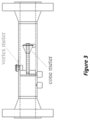
- Steven's teachings [6] disclosed a hybrid meter system that combines a vortex meter and cone DP meter ( Figure 3 ). This is a specific example of a Boden [7] mass flow meter design. Boden taught that cross-referencing of a density sensitive volume meter (e.g. a DP meter), and a density insensitive meter (e.g. a turbine, ultrasonic, or vortex meter) produces a density prediction. Combing the density insensitive meter's volume flowrate prediction with this density prediction produces a mass flowrate prediction.
- the Boden concept is a mass meter design, i.e. a flow meter that can predict the mass flow without requiring an externally obtained fluid density input.
- Boden metering system designs (such as Figure 3 ) consist of two flow meter designs in series, or two flow metering principles in one meter body, they are not in any way used to reduce the flow metering systems fluid flow prediction uncertainty.
- MLU comprises various mathematical techniques that combine a process system's multiple independent instrumentation measurements, equipment settings, associated uncertainties, and physical laws, to automatically validate data (i.e. finely adjust measured outputs) in order to reconcile measurements.
- the techniques transform raw and sometimes inconsistent data sets into a single consistent data set.
- ⁇ MLU' techniques produces a single set of process data that most probably represents the true process conditions. The operator obtains a more precise understanding of the state of the process system, and can then make better decisions about achieving and maintaining optimum process efficiency.
- MLU techniques are used on complex systems on a macro scale. Each individual instrument output, including flow meter system's output are seen as individual nodes (i.e. data values) in the overall process system. If any instrument is off line, or clearly erroneous, the MLU techniques can derive the missing information from the massed data and governing physical laws. However, MLU techniques are not applied in the micro scale, i.e. within the inner workings of individual instruments, and they are not applied within individual flow meter systems.
- MLU techniques are applied over pipe networks, the only involvement of flow meters is the standard output of each metering system being used, along with all other instrumentation outputs, as nodes in the overall pipe network MLU technique.
- the flow meter system is not in itself subject to MLU techniques.
- This proposed method utilizes the information from both flow meters, and the knowledge that they are measuring the same true flow, in such a way as to generate a model where mathematics probability theory can be applied to produce a statistical maximum likelihood estimate of that true flow given the available data.
- This statistical maximum likelihood estimate of that true flow is statistically more likely to be closer to the true flowrate value than either of the two input flowrate predictions.
- this maximum likelihood estimate flowrate prediction also has a lower associated uncertainty than either of the two individual flowrate predictions.
- the method can be extended to include more than two flow measurement devices in series.
- the method can even be extended to flow measurement devices in parallel as long as mass conservation relates their combined measured flows.
- An example would be one meter upstream of a pipe tee, and a meter on each of the branching lines downstream (e.g. see Figure 5 ).
- the method is not restricted to the conservation of mass flow, or volume flow for constant density, or for a known fluid composition the equivalent of conservation of energy flow or mole component flow rate. It can be extended to utilize other relevant laws of physics.
- One example, which is exploited in this disclosure, is the rule of 'the equivalence of measured pressure differentials'.
- the method is applicable to gas and liquid flows.
- the method termed 'MLU' is the combination of a system's multiple instrumentation readings, associated uncertainties, governing physical laws, and mathematical techniques, to automatically validate data and reconcile measurements such that the whole complies with the physical laws (such as conservation of energy, conservation of mass, or other laws related to these physical principles) and is statistically optimal in the reconciled values and their associated uncertainties.
- the technique can improve best estimates of not just measured system variables but even unmeasured variables.
- the technique transforms raw and sometimes inconsistent data sets into a single consistent data set representing the most likely truth.
- MLU techniques are typically used by the hydrocarbon production industry for product allocation in complex pipe networks owned by many parties or process plants where there are multiple independent measurements of distinct hydrocarbon streams.
- This macro system can be used to validate measurements as being compatible with respect to uncertainties and the relevant constraints, or to detect gross instrumentation errors.
- the technique often applied on this macro scale is introduced to the micro scale of flow meter systems.
- L ⁇ ln 1 2 ⁇ 2 2 1 2 ⁇ 1 2 + m ⁇ t ⁇ m ⁇ 2 2 2 ⁇ 2 2 + m ⁇ t ⁇ m ⁇ 1 2 2 ⁇ 1 2
- U ⁇ r is always less than U ⁇ 2 , for any real meter.
- U ⁇ r is always less than U ⁇ 1 .
- U ⁇ r is always less than either meter's uncertainty.
- the principle is that the higher uncertainty measurement does contain independent additional information, and even if it is less accurate than the lower uncertainty information, when the information is combined, the higher uncertainty additional information supplements the lower uncertainty information, which inherently reduces the overall measurement uncertainty.
- the invention is not restricted to one computational method or type of meter. Wherever a system is designed with multiple sensor inputs various mathematical (computational) approaches can be used to combine measurements optimally, giving reconciled finely adjusted more accurate outputs with reduced uncertainty compared to the initial inputs. Hence, although any suitable mathematical (computational) method would suffice, the text uses MLU techniques as an arbitrary example.
- the results of applying this approach to a vortex meter and cone meter operating in series are shown below.
- the data is from a 6", schedule 80, gas flow laboratory with the vortex meter upstream of the DP cone meter.
- the meters were separated by a short spool piece.
- the data consist of points at nominally 60 bar and 15 bar.
- the standalone cone meter had a mass flow prediction uncertainty of 0.6%.
- the standalone vortex meter had a mass flow prediction uncertainty of 0.75%.
- the reconciled mass flowrate prediction uncertainty is reduced to 0.47%, i.e. the combined metering system has a lower mass flowrate uncertainty than either individual meter.
- Table 1 Vortex and Cone Meter in Series with Applied MLU.
- the traditional method of metering the flow uses a single meter's uncertainty value. If the cone meter stood alone in the pipe this result would be used without any check meter verification. If there were two meters in series for check metering the standard practice is to use the meter with the lower uncertainty for billing, i.e. in this example the cone meter at 0.6% uncertainty. However, if this MLU technique is applied it is proven that the flow prediction and its associate uncertainty needs finely adjusted to 20.175 kg/s ⁇ 0.47% (see point 8 in Table 1). The custody transfer metering result has shifted to 83.62 MMSCFD ⁇ 0.39 MMSCFD, i.e. an annual flow value of $76.30 million ⁇ $359K.
- the primary flowrate has been finely altered by +0.14 MMSCFD, i.e. a billing alteration of +$127.775K per annum, while the uncertainty in the flow metering system output has dropped by 0.13% from ⁇ $457K to ⁇ $359K per year, i.e. exposure to flow metering uncertainty is reduced by $98,000 per year.
- This example utilized the method for the case where there were two independent metering systems in series (see Figure 6 ). The method will work regardless of whether the two (or more) flow meters are similar or dissimilar design. This example of two independent dissimilar flow meters in series is applicable in industry in several scenarios. It would work with check metering, it will work when a buyer and seller have separate meters in series, and it will work with hybrid meter designs, such as the vortex and cone meter combination in Figure 3 .
- a hybrid meter is one where two different metering measurements are made by sharing at least some physical components.
- Figure 3 shows an example of a hybrid meter produced by two dissimilar meters.
- some ultrasonic meter (USM) systems have more than one 'ultrasonic meter system' in the same meter body. This could be described as a hybrid of two distinct independent ultrasonic meter designs sharing the same upstream flow conditioner and the same meter body.
- As ultrasonic meters are described by their number of paths, such designs are called by the two ultrasonic meter's number of paths.
- a 4+1 ultrasonic metering system indicates one embedded four path ultrasonic metering system and one embedded one path ultrasonic metering system installed together in one meter body.
- Some ultrasonic meter designs have ⁇ bounce paths' where the transducer pair are not directly opposite from each other but send and receive signals by bouncing the ultrasonic wave off the wall. This makes no difference to the application of this technique.
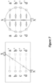
- Figure 7 shows an example of a 4+1 ultrasonic meter design.
- the 4 path chordal design has four paths created by transducer pairs a & a', b & b', c & c', d & d'.
- This four path chordal design typically has its own dedicated flow computer (or 'head').
- the 1 path design has a path created by transducer pairs x & x'.
- This one path design typically has a separate dedicated flow computer (or 'head'). That is the two ultrasonic metering systems are independent.
- Ultrasonic meter manufacturers use such meter designs to give an extra level of system redundancy, e.g. check metering, and to offer an extra diagnostic capability (e.g.
- the 1 path meter may be positioned in the vertical axis and can therefore be adversely affected by problems such as contamination or liquids at the base of the meter before the four path meter diagnostic system can see the problem).
- problems such as contamination or liquids at the base of the meter before the four path meter diagnostic system can see the problem.
- ultrasonic meter manufacturers There is no attempt by ultrasonic meter manufacturers to cross reference the two (or more) independent meters in order to reduce the overall system flowrate prediction uncertainty.
- any such ultrasonic metering system with two such systems e.g. 4+1, 4+2, 4+4 etc.
- the next example shows the method being applied to 4+1 path ultrasonic meter data.
- the 4-path and 1-path measured flow rates are treated as being independent.
- Ultrasonic meters are used to determine the volume flow rate.
- Ancillary calculations are applied to derive the fluid density from which a mass flow rate is then derived.
- the reconciliation calculations equations 15 and 20 apply in any situation where the same quantity is independently measured by different means.
- a reconciled volume or mass flow rate can be derived and its uncertainty calculated. Equations 15 and 20 can then be applied to obtain a reconciled volume or mass flow rate.
- This example utilized the method for the case where the metering system inherently had two pre-existing independent but similar metering systems to compare. However, most standalone meters do not have two such independent sub-system flowrate predictions as a standard commercial offering. However, it is sometimes possible to add a supplemental system (or systems) to produce a second flowrate prediction.
- the next example shows a case where a standard flow meter with no inherent suitable extra instrumentation is modified to produce a second flow meter system such that the method can be applied.
- Coriolis meters produce a single mass flowrate prediction.
- Standard Coriolis meters have no second mass flow prediction in which to apply this method. But a second mass flowrate prediction can be created.
- the permanent pressure loss can be read across the Coriolis meter, see Figure 8 .
- This permanent pressure loss is directly related to the fluid velocity, and therefore the mass flow.
- the mass flowrate can therefore be calculated from this read permanent pressure loss DP.
- This flow metering concept is fundamentally the same as that discussed in the DP meter diagnostic / validation section 2.2. Equation 4 is applicable for the permanent pressure loss across any pipe obstruction, DP meter and Coriolis meter inclusive.
- reading the permanent pressure loss across the Coriolis meter i.e. the differential pressure between pressure taps 1 and 3 (see Figure 8 ) creates a second independent mass flowrate prediction.
- some Coriolis meters are installed with a reduced bore assembly, see Figure 8 . In this scenario there is the option to read the differential pressure across the reduction in bore, i.e. the differential pressure between pressure taps 1 and 2, thereby effectively creating an upstream Venturi meter.
- a Coriolis meter is calibrated to have a gas mass flowrate of 0.5%. This is a typical Coriolis meter uncertainty.
- the permanent pressure loss across a typical Coriolis meter is such that a calibrated permanent pressure loss Coriolis flow meter could have an uncertainty of 0.75%.
- Carrying out the MLU technique produces a reconciled (finely adjusted) flowrate prediction, and drops the uncertainty to 0.42%.
- the Maximum Likelihood Uncertainty' system can then reduce the metering system's uncertainty.
- most flow meters are operated without diagnostic systems. Hence, the extra DP transmitter/s could be added to any DP meter without the diagnostics system, the meter can be assumed to be working correctly, and the Maximum Likelihood Uncertainty system will then reduce the metering systems flowrate prediction uncertainty.
- the prior art diagnostic system requires a standard DP meter, and then a non-standard geometry change of a third pressure tapping downstream of the meter, and the addition of one or two extra DP transmitters, for the specific reason of producing redundant flowrate predictions, and applying diagnostic algorithms to check the health of the meter.
- This disclosure provides a standard DP meter, and then a non-standard geometry change of a third pressure tapping downstream of the meter, and the addition of one or two extra DP transmitters, for the distinctly different specific reason of applying MLU algorithms to reduce a correctly operating metering system's overall flowrate prediction uncertainty.
- the present disclosure involves use of multiple instruments in conjunction with physical laws to reduce the metering system's overall uncertainty.
- the multiple instruments are reading different but related signals, i.e. the three DPs are all 'dependent' on the meter body's pressure field.
- the general term 'dependent' is here defined as systems of flow rate predictions that share some, or all, of a common set of input variables.
- Equation set 2a, 3a, and 4a are the expanded versions of the DP meter Equation set 2, 3, and 4, where A and ⁇ are geometry terms, ⁇ denotes fluid density, Y denotes the expansion factor, and C d , K r , and K PPL are the DP meter flow coefficients
- constraints listed above could be augmented with inequality constraints to ensure calculations result in positive values for reconciled variables.
- constraints would be dependent on the meter and relevant measured and unmeasured variables.
- J x J 11 0 0 J 14 J 15 0 0 J 18 0 J 22 0 0 0 J 26 0 J 28 0 0 J 33 0 0 0 J 37 J 38 1 ⁇ 1 ⁇ 1 0 0 0 0 0 0 0
- V ⁇ ⁇ P t 2 ⁇ 0 ⁇ ⁇ ⁇ 0 ⁇ ⁇ ⁇ 2
- Measured values are used as inputs to x 0 in the first iteration.
- An initial estimate of the mass flow rate used in the first iteration, u 0 can be set from any one, or any combination, of the traditional, recovered and PPL calculated mass flow rates, e.g. an arithmetic average or uncertainty weighted average.
- This example's data set is from a 14" (35.56 cm) 0.56 beta cone DP meter calibrated at a natural gas calibration facility.
- the meter had an inlet diameter of 0.337 m and cone diameter of 0.28 m. Cone meter geometry uncertainty is accounted for in the calibrated flow coefficient data. This standalone cone meter's mass flowrate prediction uncertainty is 0.78% at the flow rate in this example.
- V diag (1045.825, 66.254, 1045.80, 1.60E-09, 1.81E-05, 1.30E-03, 1.18E-05, 8.22E-03)
- the derived traditional, recovered and PPL mass flow rates calculated according to Equations 2, 3, & 4 are shown in Table 4 along with their arithmetic average.
- the arithmetic average is the input into vector u of equation 30.
- Alternative methods to calculate the mass flow rate for input into vector u could be used, such as an uncertainty weighted average mass flow rate, or simply choosing the traditional mass flow rate as it typically has the lowest uncertainty.
- the Jacobian matrix, J x derived from the constraints of equations 26 to 29 is the 4x8 matrix with entries according to Table 5. The rows correspond to the constraints applied to cone meter measurements and the columns are the measured variables to be reconciled. Table 5. 14", 0.56 ⁇ Cone Meter 1 st Iteration Jacobian for Metered Variables and Parameters.
- the Jacobian matrix, J u derived from equation 34 is the 4x1 matrix with entries according to Table 6. Again, the rows represent the constraints applied to the system and the columns are the unknown variables to be reconciled, in this case the mass flow rate. Table 6. 14", 0.56 Beta Cone DP Meter Jacobian for unmeasured variables. m DP t 1 DP r 1 DP PPL 1 Delta P 0
- Equation 30 and 31 results in the following corrections being derived and new values for the measured and unmeasured variables as shown in Table 8.
- the Initial Value column shows the value of each measured and unmeasured variable before reconciliation.
- the Reconciled Value at Start of Iteration column shows the value of each variable calculated in the previous iteration of the MLU calculation. In the first iteration this is the Initial Value of each variable.
- the Correction column shows the correction to each variable calculated by the MLU equations 30 and 31.
- Table 8 also shows convergence test results. Convergence is checked in both the measured variables and unmeasured variables. In the measured variables convergence is checked by taking the sum of the absolute values of the difference between reconciled variables at the start and end of each iteration, S m .
- the Jacobian matrix, J x derived from the constraints of equations 26 to 29 is the 4x8 matrix with entries according to the 'Reconciled Value at End of Iteration' column Table 8. The iteration will continue until convergence is achieved. In this example convergence is achieved on the third iteration. The result of this third iteration is shown as Table 8.
- the stand-alone 14" cone meter reads 10.613 kg/s at 0.78% relative uncertainty.
- Measured input variables, relative uncertainties and absolute uncertainties are listed in Table 9. These measurements comprise the inputs into the vector x in equation 23 and the covariance matrix, V , in equation 35.
- V diag(811074.3, 56414.8, 439339.5, 6.5E-10, 6.5E-08, 9E-06, 9.2E-06, 3.04E-4, 3.2E-06, 9.6E-03)
- Measurement Unit Value Percent Uncertainty Absolute Uncertainty DP t Pa 90059.66 1.00% 900.597 DP r Pa 23751.81 1.00% 237.518 DP PPL Pa 66282.69 1.00% 662.827 d m 0.051 0.05% 0.000 D m 0.102 0.25% 0.000 Y Dimensionless 0.991 0.30% 0.003 C d Dimensionless 0.605 0.50% 0.003 K r Dimensionless 1.162 1.50% 0.017 K PPL Dimensionless 0.178 1.00% 0.002 ⁇ kg/m 3 36.304 0.27% 0.098
- the Jacobian matrix, J x derived from the constraints of equations 26 to 29 is the 4x10matrix with entries according to Table 11. The rows correspond to the constraints applied to the orifice meter measurements and the columns are the measured variables to be reconciled.
- the Jacobian matrix, J u derived from equation 34 is the 4x1 matrix with entries according to Table 12. Again, the rows represent the constraints applied to the system and the columns are the unknown variables to be reconciled, in this case the mass flow rate.
- the Jacobian matrix, J x derived from the constraints of equations 26 to 29 is the 4x10 matrix with entries according to the 'Reconciled Value at End of Iteration' column Table 13. Iteration will continue until convergence is achieved. In this example convergence is achieved on the fourth iteration.
- Table 13 First Iteration of Orifice Meter's ⁇ Maximum Likelihood Uncertainty' Convergence Check.
- the stand-alone 4" orifice meter reads 3.208 kg/s at 0.79%.
- the method is not limited to DP meters with three independent DP measurements, but applies to any meter with two or more measurements.
- This disclosure provides for taking the physical assembly of two (or more) flow meters, or one meter with additional instrumentation, and comparing the resulting data set as a whole to physical law/s such that discrepancies arising from instrument reading uncertainty are mitigated.
- the result is the production of a single set of data more accurately representing the likely physical reality.
- This includes an optimised ⁇ Maximum Likelihood Uncertainty', i.e. a more precise and trustworthy flowrate prediction.
- the particular choice of mathematical techniques used to operate the method can vary. The examples given above are just that, examples. There are various mathematical techniques that can be applied to solve such a mathematical problem.
- some mathematical techniques offer the potential of taking the combined data sets of the multiple instrumentation and the associated physical constraints, and eking out further nuggets of useful information. The following are a selection of optional mathematical techniques. This list is not exhaustive.
- Robust MLU [13] provides a means by which the least-squares MLU approach can be made less sensitive to gross errors. It is also applicable if the assumption that measurement uncertainties follows a normal distribution is known or suspected not to be valid, and instead follows a different distribution.
- Robust MLU differs from the standard MLU approach defined above by altering the Covariance matrix according to the probability distributions from which measurement errors are expected to follow.
- Possible probability distributions could be, but are not limited to: Contaminated Gaussian; Cauchy, Logistic, Lorentzian, Fair Function, or Hempel's Redescending M-Estimator.
- the Contaminated Gaussian probability density function is the sum of these two distributions P x i
- x ⁇ i , ⁇ 1 , ⁇ 2 ⁇ P 1 , i + 1 ⁇ ⁇ P 2 , i where 0 ⁇ ⁇ ⁇ 1.
- the method described above applies multiple measurements at one point or period in time to derive best estimates of variables.
- filtering techniques can be applied. That is, the method can be extended from an essentially static data set to dynamic data analysis. For instance, Reynolds number (a dimensionless expression of flowrate) can vary with time, and a DP meter's discharge coefficient varies with Reynolds number.
- an orifice meter's Pressure-Loss-Ratio (the ratio of permanent pressure loss to primary DP) is a function of discharge coefficient, meter geometry and Reynolds number.
- Kalman Filters are typically used to model dynamic systems where a linear relationship defines evolution of the system state with time. For the case of a flow meter this can be modified to considering a non-linear evolution of the flow meter's state with flowrate. The non-linear evolution is due to the non-linear relationship between the mass flowrate and the state variables, (e.g. for DP meters: m ⁇ ⁇ ( ⁇ P). Hence, for this non-linear case an ⁇ Extended Kalman Filter' is required. This Extended Kalman Filter would model the flow metering system's non- linear evolution with flowrate (instead of time). By analyzing multiple data grabs at different flow rates an Extended Kalman Filter (EKF) could reduce flow rate uncertainty and/or parameter estimation thereby even calibrating the DP meter in-situ.
- EKF Extended Kalman Filter
- the EKF works in a two-step process.
- the Kalman filter produces estimates of the current state variables, along with their uncertainties. This requires a physical model, representing the underlying dynamics of the system, to calculate the current state from the latest estimates. Once the outcome of the next measurement is observed (naturally corrupted with some amount of uncertainty, including random noise), these estimates are updated (in the update step ) using an uncertainty weighted average, with more weight being given to estimates with lower uncertainty.
- Such an algorithm is recursive in that it uses only the present input measurements, the previously calculated state and the uncertainties in each of these; no additional past information is required.
- the flow meter Kalman filter comprises the flow meter data reconciliation (MLU) method extended into the time domain.
- MLU flow meter data reconciliation
- Time provides an extra dimension in which repeated measurements by the same instruments generate additional information that can be exploited by the MLU techniques to improve the estimates of flow rate and further reduce its uncertainty. It exploits temporal dependencies using a model that describes how the flow meter system parameters and variables propagate from one time step to the next. It uses the same weighted least square uncertainties, as flow meter data reconciliation MLU, to update the values of the parameters and variables in the system.
- the flow meter Extended Kalman Filter uses a process model to predict how the dynamic flow metering system's variables and parameters propagate from one time step to the next, and reconciles these with a series of measurements with statistical noise (i.e. uncertainty) observed over time. It does this in a statistically optimal fashion and produces estimates of the variables and parameters that tend to be more precise than those based on measurements alone.
- a DP meter that monitors the meter's axial pressure profile has three flow equations using three flow coefficients. For ostensibly constant flow conditions, with associated constant Reynolds number, these flow coefficients are ostensibly constant in time. Any small fluctuation in flow conditions produces corresponding small fluctuations in Reynolds number are flow coefficients. This extra information can be incorporated into the MLU technique using the Kalman Filter.
- the flow meter Kalman filter algorithm works in a two-step process as indicated schematically in Figure 11 .
- the Kalman filter produces estimates of the current state variables, along with their uncertainties. Once the outcome of the next measurement (necessarily with some uncertainty including random noise) is observed, these estimates are updated (in the update step) using a weighted average, with more weight being given to estimates with lower certainty.
- the algorithm is recursive in that it uses only the present input measurements and the previously calculated state and its uncertainty matrix; no additional past information is required.
- Six state variables of a DP measurement system can be defined as:
- the 'modified' coefficients are derived from the discharge, expansion, and permanent pressure loss coefficients C d , K r and K PPL respectively.
- the first equation in the predict phase of the DP meter Kalman filter employs the transition matrix, which predicts how the state variables from the previous time step (t-1) propagate to the current time step (t).
- the filter is provided with initial estimates of the values of these parameters and their uncertainty. However, their true value is unknown, only that the true value remains constant in time.
- the Kalman filter uses this information and the DP measurements to update its estimate of these parameters and improve the uncertainties of those estimates.
- the three differential pressures can vary unpredictably as dictated by the fluctuations in the process from one time step to the next.
- the process noise represents the uncertainty in the physical model.
- This step updates the state variables using the data from available measurements. It also imposes the mass and pressure balance constraints associated with the system.
- the available measurements are the three differential pressure measurements.
- the DP measurements are necessarily uncertain and hence the Kalman filter's estimates of the values of the constant but unknown flow coefficients are updated using a weighted average of all estimates and measurements, with more weight being given to those with lower uncertainty.
- the constraints are also imposed, and to ensure they are complied with the coefficients and measured differential pressures, are adjusted accordingly.
- the filter's behaviour can be considered in terms of gain.
- the Kalman gain is a function of the relative uncertainty of the measurements and current estimates of the flow coefficients. These can be tuned to achieve a particular performance. With high gain, the filter places more confidence on the measurements, and thus follows them more closely. With low gain, the filter follows the model predictions more closely, smoothing out noise but decreasing the responsiveness. The gain is adjusted using the process noise described in the Predict Step.
- the uncertainties of the state variables i.e. the updated coefficients and DPs, are also filter outputs. These are in the form of a covariance matrix. This covariance matrix, along with the uncertainty in the fluid density, is used in the determination of the uncertainty in the calculated mass flow rate at each time step.
- the DP flow meter filter's calculated state variables and their associated uncertainties at the current time step, t form the inputs to the calculations of the next time step, t + 1. This is the filter's recursive nature. All information required to perform the calculations in the next time step is contained within the estimates and uncertainties from the current time step.
- the 'Extended' Kalman filter technique being employed here is necessary to handle the non-linear constraint, and its discrete nature is due to it being applied at discrete time intervals rather than continuously (though the time intervals are short in duration).
- the parameter C d ' can be considered a modified discharge coefficient parameter (where the constant geometry terms and variable expansion factor are added).
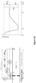
- Figure 16 shows the evolution of this modified discharge coefficient with time. This plot illustrates how the Kalman filter adjusts this parameter to a stable and consistent value.
- the Extended Kalman Filter is not the only suitable filtering approach.
- other filtering techniques which could be applied are the Unscented Kalman Filter and the H ⁇ filter.
- the linearization approximation of the EKF may be unsuitable and more accurate predictions of a system's state and associated uncertainty can be determined from the Unscented Kalman Filter.
- H ⁇ (H-infinity) mathematical procedures are generally employed in control systems.
- the system expresses the metering problem as a mathematical optimization problem.
- H ⁇ mathematical techniques were developed to deal with multivariable systems and cross-referencing of different sub-systems and the inventors have realized that they are useful in this application.
- the H ⁇ technique is also applicable when assumptions around process and measurement noise necessary for the EKF (such as known distributions and zero means) are not applicable.
- the H ⁇ method is a robust version of the Kalman Filter.
- the known disadvantage of H ⁇ methods is their dependence on a strong physical model. However, in this application the physical model (i.e. the flow meter's physical operation) is indeed well understood and the physical model is analogous with the physical law constraints we are putting on the combined data.
- H ⁇ mathematics is another potential mathematical tool to analyze the inventions resulting combined data with physical constraints.
- the Robust MLU based approach described above requires the uncertainties in the input independent variables. In the examples thus far these uncertainties have been based on manufacturer's data or calculated in accordance with the relevant standards, e.g. ISO 5167-2 [14] for orifice meters, ISO 17089-1 [15] for ultrasonic meters, ASME MFC-6-2013 [16] for vortex meters etc..
- the GUM [8] defines these uncertainties as Type B.
- Flow meter manufacturer's 'catch all' uncertainty statements are generic statements to cover multiple applications. In specific applications it is possible that a flow meter's uncertainty will be more or less than the manufacturer's generic statement. Properly installed, and used within the calibrated flow conditions ranges, a flow meter may have lower uncertainty than quoted by the manufacturer. However, if used in adverse flow conditions, or outside the calibrated flow range, a flow meter's uncertainty may be higher than quoted by the manufacturer. In such a scenario there is no reliable manufacturer or standards baseline flow meter uncertainty available. However, in this scenario it is possible to apply this disclosed method, i.e. to cross-reference multiple instrument readings with physical laws, and predict the actual uncertainties.
- Bayesian updating provides a posterior probability distribution of the values of the various parameters and independent and dependent variables. It also provides the probability distribution of the range of uncertainties of those same parameters and variables. According to Bayes theorem, the posterior probability of the value of a variable is proportional to the product of the prior probability of that value and the likelihood of the data observed given that value of the variable.
- the posterior probability (left-hand side of equation 42) can be differentiated with respect to ( ⁇ t ) to obtain the most probable value of the true flow given the meter readings and their quoted uncertainties.
- the second derivative provides the standard deviation (or uncertainty) in the most probable value of the true flow.
- the Bayesian formulation allows the problem to be expressed more generally and to allow the probability distributions associated with the uncertainties in the input variables to be included: P m ⁇ t , ⁇ 2 , ⁇ 1
- the prior probability distributions of the standard deviations can be based on a ⁇ Jeffrey's (uninformed) prior' updated using the quoted manufacturer's uncertainties.
- the resultant joint probability distribution can be marginalized to obtain the standard deviation (or uncertainty) in ( ⁇ t ) by integrating out the contribution of the two, meter standard deviations.
- updated uncertainties in the individual meter's readings can be obtained by marginalizing the true flow and the other meter's standard deviation.
- the standard deviation of the input parameters can be included and updated based on the data using this Bayesian formulation.
- the generation of the joint posterior distribution and the marginalization of variables may require numerical approaches such as 'Markov Chain Monte Carlo' methods.
- the present disclosure of taking the physical assembly of two (or more) flow meters, or one meter with additional instrumentation, and comparing the resulting data set as a whole to the inherent constraints of physical law/s, allows for various different mathematical techniques to be employed as tools to extract the information. Indeed, different mathematical techniques can eke out different pieces of information buried within these data sets with physical constraints. Such a system could use more than one mathematical technique concurrently to analyze the resulting data and its physical constraints. There is no constraint on the mathematical procedure/s chosen and the list above is not exhaustive. The examples above show that such data with physical constraints does contain information where the flowrate prediction uncertainty can be reduced, and the mass flowrate prediction finely adjusted. But other advantages and information is also attainable from the general disclosed method, such as the potential for self-calibration of meters in-situ, deriving flowrate prediction uncertainties when the meter is used outside its stated flow condition range, gross error detection etc.
- FIG. 17 showing a flow metering system which has a first measuring device producing a first flow rate reading, and a second measuring device producing a second flow rate reading.
- the readings are provided to a calculation device, which then operates as described here to produce a flow rate prediction, also called a reconciled flow, and its associated uncertainty.
Landscapes
- Physics & Mathematics (AREA)
- Fluid Mechanics (AREA)
- General Physics & Mathematics (AREA)
- Measuring Volume Flow (AREA)
Claims (15)
- Verfahren zum Messen einer Fluidströmung, umfassend:Verwenden eines ersten Strömungsmessers zum Erzeugen eines ersten Strömungsratenmesswerts der zu messenden Strömung mit einer zugehörigen ersten Unsicherheit;Verwenden eines zweiten Strömungsmessers zum Erzeugen eines zweiten Strömungsratenmesswerts der zu messenden Strömung mit einer zugehörigen zweiten Unsicherheit;und gekennzeichnet durch:Berechnen einer Strömungsratenvorhersage basierend auf der Kombination aus dem ersten Strömungsratenmesswert, dem zweiten Strömungsratenmesswert, der ersten Unsicherheit, der zweiten Unsicherheit und Anwenden von Kriterien, die auf physikalischen Gesetzen basieren;wobei die Strömungsratenvorhersage eine zugehörige Unsicherheit aufweist, die geringer als jede der ersten Unsicherheit und der zweiten Unsicherheit ist.
- Verfahren nach Anspruch 1, wobei der erste und der zweite Strömungsmesser in Reihe geschaltet sind.
- Verfahren nach Anspruch 2, wobei der oder jeder des ersten und des zweiten Strömungsmessers einen Satz parallel verbundener, untergeordneter Strömungsmesser umfasst.
- Verfahren nach Anspruch 1, wobei der erste und der zweite Strömungsmesser nach den gleichen physikalischen Prinzipien arbeiten.
- Verfahren nach Anspruch 1, wobei der erste und der zweite Strömungsmesser nach unterschiedlichen physikalischen Prinzipien arbeiten.
- Verfahren nach Anspruch 1, wobei der erste und der zweite Strömungsmesser Untersysteme in einem einzigen Hybrid-Strömungsmessergehäuse sind.
- Verfahren nach Anspruch 4, wobei die Messuntersysteme unabhängige Ultraschallwandlersätze in einem Ultraschallmessergehäuse sind, die zwei oder mehr unabhängige Strömungsratenmesswerte erzeugen.
- Verfahren nach Anspruch 5, wobei die Untersysteme Folgendes umfassen:(a) einen Wirbelmesser und ein Konusmesser, die gemeinsam in einem Hybridzählergehäuse eingesetzt sind, die zwei oder mehr unabhängige Strömungsratenmesswerte erzeugen; oder(b) ein primäres Strömungsmessersystem mit einem sekundären, unabhängigen Differenzdruckmesser, der durch Ablesen eines oder mehrerer Differenzdrücke über zwei Punkte in dem primären Strömungsmessersystem gebildet wird; oder(c) einen unabhängigen Coriolis-Messer und einen unabhängigen Differenzdruckmesser, der durch Ablesen eines Differenzdrucks zwischen zwei Punkten über dem Gehäuse des Coriolis-Messers gebildet wird, die zwei unabhängige Strömungsratenmesswerte erzeugen.
- Verfahren nach Anspruch 1, wobei ein Strömungsmesssystem ein primäres Fluidsperrelement und drei Druckentnahmestellen umfasst, die an Positionen stromaufwärts, strommittig beziehungsweise stromabwärts in Bezug auf das primäre Fluidsperrelement bereitgestellt sind; und wobei der erste und der zweite Strömungsmesser jeweils durch Messen eines beliebigen Paars von Folgenden bereitgestellt sind:(i) einem Differenzdruck des permanenten Druckverlusts (PPL), der zwischen den Druckentnahmestellen stromaufwärts und stromabwärts erfasst wird;(ii) einem herkömmlichen Differenzdruck, der zwischen den Druckentnahmestellen stromaufwärts und strommittig erfasst wird; und(iii) einem wiederhergestellten Differenzdruck, der zwischen den Druckentnahmestellen strommittig und stromabwärts erfasst wird;um den ersten und zweiten Strömungsratenmesswert zu erzeugen.
- Verfahren nach Anspruch 1, wobei der erste und der zweite Strömungsmesser vor der Verwendung kalibriert werden.
- Verfahren nach Anspruch 1, wobei die Strömung eine Nassgasströmung ist.
- Verfahren nach Anspruch 1, wobei das Berechnen einer Strömungsratenvorhersage Anwenden eines erweiterten Kalman-Filters umfasst, um Systemparameter, Schätzungen und ihre zugehörigen Unsicherheiten zu reduzieren, wodurch das Strömungsmesssystem in situ kalibriert wird.
- Verfahren nach Anspruch 1, wobei das Berechnen einer Strömungsratenvorhersage Anwenden eines von Folgenden umfasst: robuste Maximum-Likelihood-Unsicherheit; erweiterter Kalman-Filter; Unscented Kalman-Filter; H-Infinity-Filter; und Bayessche Aktualisierung.
- Fluidströmungsmesssystem, umfassend:einen ersten Strömungsmesser, der zum Erzeugen eines ersten Strömungsratenmesswerts einer zu messenden Strömung, der eine zugehörige erste Unsicherheit aufweist, konfiguriert ist;einen zweiten Strömungsmesser, der zum Erzeugen eines zweiten Strömungsratenmesswerts der zu messenden Strömung, der eine zugehörige zweite Unsicherheit aufweist, konfiguriert ist; und gekennzeichnet durcheine Berechnungsvorrichtung, die zum Berechnen einer Strömungsratenvorhersage basierend auf der Kombination aus dem ersten Strömungsratenmesswert, dem zweiten Strömungsratenmesswert, der ersten Unsicherheit, der zweiten Unsicherheit und durch Anwenden von Kriterien, die auf physikalischen Gesetzen basieren, konfiguriert ist;wobei die Strömungsratenvorhersage eine zugehörige Unsicherheit aufweist, die geringer als jede der ersten Unsicherheit und der zweiten Unsicherheit ist.
- Computerprogrammprodukt, Anweisungen umfassend, die bei Ausführung auf einer Vorrichtung, die eines von einem Computer, einem dedizierten Strömungscomputer oder einer Schaltung ist, die Vorrichtung zu Folgendem konfigurieren:Empfangen eines ersten Strömungsratenmesswerts einer zu messenden Strömung von einem ersten Strömungsmesser mit einer zugehörigen ersten Unsicherheit;Empfangen eines zweiten Strömungsratenmesswerts von einem zweiten Strömungsmesser der zu messenden Strömung mit einer zugehörigen zweiten Unsicherheit; und dadurch gekennzeichnet, dass die Vorrichtung zu Folgendem konfiguriert ist:Berechnen einer Strömungsratenvorhersage basierend auf der Kombination aus dem ersten Strömungsratenmesswert, dem zweiten Strömungsratenmesswert, der ersten Unsicherheit, der zweiten Unsicherheit und Anwenden von Kriterien, die auf physikalischen Gesetzen basieren;wobei die Strömungsratenvorhersage eine zugehörige Unsicherheit aufweist, die geringer als jede der ersten Unsicherheit und der zweiten Unsicherheit ist.
Applications Claiming Priority (2)
| Application Number | Priority Date | Filing Date | Title |
|---|---|---|---|
| US201962914073P | 2019-10-11 | 2019-10-11 | |
| PCT/GB2020/052535 WO2021069932A1 (en) | 2019-10-11 | 2020-10-09 | Improvements relating to fluid flow measurement |
Publications (2)
| Publication Number | Publication Date |
|---|---|
| EP4042115A1 EP4042115A1 (de) | 2022-08-17 |
| EP4042115B1 true EP4042115B1 (de) | 2024-10-30 |
Family
ID=73401842
Family Applications (1)
| Application Number | Title | Priority Date | Filing Date |
|---|---|---|---|
| EP20807092.0A Active EP4042115B1 (de) | 2019-10-11 | 2020-10-09 | Verbesserungen im zusammenhang mit flüssigkeitsstrommessungen |
Country Status (4)
| Country | Link |
|---|---|
| US (1) | US20240094036A1 (de) |
| EP (1) | EP4042115B1 (de) |
| CA (1) | CA3154212A1 (de) |
| WO (1) | WO2021069932A1 (de) |
Families Citing this family (5)
| Publication number | Priority date | Publication date | Assignee | Title |
|---|---|---|---|---|
| DE102021127850A1 (de) | 2021-10-26 | 2023-04-27 | Endress+Hauser Flowtec Ag | Verfahren zum Ermitteln eines Masseanteils der Gasphase und/oder der Massedurchflussrate der Gasphase, eines in einem Messrohr strömenden mehrphasigen Mediums mit einer Flüssigkeitsphase und einer Gasphase und Messaufnehmer dafür |
| WO2023183403A1 (en) * | 2022-03-22 | 2023-09-28 | Chevron U.S.A. Inc. | Correction of gas flow in the presence of liquid in a gas pipeline |
| EP4508397A1 (de) * | 2022-04-12 | 2025-02-19 | Micro Motion, Inc. | Druckkompensation eines fluidstromparameters |
| EP4446707A1 (de) * | 2023-04-13 | 2024-10-16 | Waltero Holding AB | Kategorisierung einer diskrepanz bei einer messauslesung eines durchflussmessers |
| CN117588736B (zh) * | 2024-01-18 | 2024-05-10 | 常州高凯电子有限公司 | 一种压电式高温水蒸气发生器控制系统及方法 |
Citations (1)
| Publication number | Priority date | Publication date | Assignee | Title |
|---|---|---|---|---|
| WO2018195368A1 (en) * | 2017-04-20 | 2018-10-25 | Schlumberger Technology Corporation | Detecting and correcting for discrepancy events in fluid pipelines |
Family Cites Families (6)
| Publication number | Priority date | Publication date | Assignee | Title |
|---|---|---|---|---|
| US2772567A (en) | 1953-08-21 | 1956-12-04 | North American Aviation Inc | Mass flowmeter |
| WO2008025934A1 (en) | 2006-08-29 | 2008-03-06 | Richard Steven | Improvements in or relating to flow metering |
| GB2453704B (en) | 2006-08-29 | 2011-11-02 | Richard Steven | Improvements in or relating to flow metering |
| US20120095733A1 (en) * | 2010-06-02 | 2012-04-19 | Schlumberger Technology Corporation | Methods, systems, apparatuses, and computer-readable mediums for integrated production optimization |
| US11680833B2 (en) | 2013-05-04 | 2023-06-20 | Richard Steven | Flow metering |
| US20180073904A1 (en) * | 2016-09-14 | 2018-03-15 | General Electric Company | Estimation approach for use with a virtual flow meter |
-
2020
- 2020-10-09 US US17/768,098 patent/US20240094036A1/en active Pending
- 2020-10-09 EP EP20807092.0A patent/EP4042115B1/de active Active
- 2020-10-09 CA CA3154212A patent/CA3154212A1/en active Pending
- 2020-10-09 WO PCT/GB2020/052535 patent/WO2021069932A1/en not_active Ceased
Patent Citations (1)
| Publication number | Priority date | Publication date | Assignee | Title |
|---|---|---|---|---|
| WO2018195368A1 (en) * | 2017-04-20 | 2018-10-25 | Schlumberger Technology Corporation | Detecting and correcting for discrepancy events in fluid pipelines |
Also Published As
| Publication number | Publication date |
|---|---|
| EP4042115A1 (de) | 2022-08-17 |
| CA3154212A1 (en) | 2021-04-15 |
| WO2021069932A1 (en) | 2021-04-15 |
| US20240094036A1 (en) | 2024-03-21 |
Similar Documents
| Publication | Publication Date | Title |
|---|---|---|
| US20240094036A1 (en) | Improvement relating to fluid flow measurement | |
| US7636640B2 (en) | Multi-gas flow device | |
| EP3580427B1 (de) | Verfahren zur beurteilung und verwaltung von sensorunsicherheiten in einem virtuellen durchflussmesser | |
| Choi et al. | In-situ observation and calibration in building digitalization: Comparison of intrusive and nonintrusive approaches | |
| EP2592395B1 (de) | Bestimmung einer Durchflussmenge | |
| WO2008025935A1 (en) | Improvements in or relating to flow metering | |
| EP3287750B1 (de) | Gaszählersystem und verfahren zur schätzung des heizwerts | |
| SG177731A1 (en) | Method and apparatus for determining and compensating for a change in a differential zero offset of a vibrating flow meter | |
| EP3889555B1 (de) | Durchflussmesserkalibrierverfahren | |
| Wilson et al. | Data Reconciliation in Microcosm–Reducing DP Meter Uncertainty | |
| Jousten et al. | Final report of key comparison CCM. P-K12 for very low helium flow rates (leak rates) | |
| Adefila et al. | Calibration of an averaging pitot tube for gaseous CO 2 flowmetering | |
| Couput et al. | Operational experience with virtual flow measurement technology | |
| Gugole et al. | Assessment of alternative fluid calibration to estimate traceable liquefied hydrogen flow measurement uncertainty | |
| Lira et al. | Error-in-variables models in calibration | |
| Lunde et al. | Handbook of Uncertainty Calculations: Ultrasonic Fiscal Oil Metering Stations | |
| Johnson et al. | Uncertainty and traceability for the CEESI Iowa natural gas facility | |
| WO2013017876A1 (en) | An aid in validating flow measurement equipment | |
| Fry | Measurement validation via expected uncertainty | |
| Brown et al. | LNG allocation metering using 8-path ultrasonic meters | |
| Pobitzer et al. | Systematic bias in pro rata allocation schemes | |
| Razaghi et al. | Uncertainty calculations for a crude oil metering system including bidirectional pipe prover, automatic sampling system and water draw; North Yaran Oil Field case study | |
| Valasubramanian | Minimize Measurement Uncertainties to Gain More | |
| Gilarranz | Uncertainty Analysis of a Polytropic Compression Process and Application to Centrifugal Compressor Performance Testing | |
| Ifft | Custody Transfer Flow Measurement with New Technologies |
Legal Events
| Date | Code | Title | Description |
|---|---|---|---|
| STAA | Information on the status of an ep patent application or granted ep patent |
Free format text: STATUS: UNKNOWN |
|
| STAA | Information on the status of an ep patent application or granted ep patent |
Free format text: STATUS: THE INTERNATIONAL PUBLICATION HAS BEEN MADE |
|
| PUAI | Public reference made under article 153(3) epc to a published international application that has entered the european phase |
Free format text: ORIGINAL CODE: 0009012 |
|
| STAA | Information on the status of an ep patent application or granted ep patent |
Free format text: STATUS: REQUEST FOR EXAMINATION WAS MADE |
|
| 17P | Request for examination filed |
Effective date: 20220425 |
|
| AK | Designated contracting states |
Kind code of ref document: A1 Designated state(s): AL AT BE BG CH CY CZ DE DK EE ES FI FR GB GR HR HU IE IS IT LI LT LU LV MC MK MT NL NO PL PT RO RS SE SI SK SM TR |
|
| DAV | Request for validation of the european patent (deleted) | ||
| DAX | Request for extension of the european patent (deleted) | ||
| GRAP | Despatch of communication of intention to grant a patent |
Free format text: ORIGINAL CODE: EPIDOSNIGR1 |
|
| STAA | Information on the status of an ep patent application or granted ep patent |
Free format text: STATUS: GRANT OF PATENT IS INTENDED |
|
| INTG | Intention to grant announced |
Effective date: 20240228 |
|
| GRAS | Grant fee paid |
Free format text: ORIGINAL CODE: EPIDOSNIGR3 |
|
| GRAA | (expected) grant |
Free format text: ORIGINAL CODE: 0009210 |
|
| STAA | Information on the status of an ep patent application or granted ep patent |
Free format text: STATUS: THE PATENT HAS BEEN GRANTED |
|
| AK | Designated contracting states |
Kind code of ref document: B1 Designated state(s): AL AT BE BG CH CY CZ DE DK EE ES FI FR GB GR HR HU IE IS IT LI LT LU LV MC MK MT NL NO PL PT RO RS SE SI SK SM TR |
|
| REG | Reference to a national code |
Ref country code: GB Ref legal event code: FG4D |
|
| REG | Reference to a national code |
Ref country code: CH Ref legal event code: EP |
|
| REG | Reference to a national code |
Ref country code: DE Ref legal event code: R096 Ref document number: 602020040431 Country of ref document: DE |
|
| REG | Reference to a national code |
Ref country code: IE Ref legal event code: FG4D |
|
| REG | Reference to a national code |
Ref country code: LT Ref legal event code: MG9D |
|
| REG | Reference to a national code |
Ref country code: NL Ref legal event code: MP Effective date: 20241030 |
|
| REG | Reference to a national code |
Ref country code: CH Ref legal event code: PK Free format text: BERICHTIGUNGEN |
|
| PG25 | Lapsed in a contracting state [announced via postgrant information from national office to epo] |
Ref country code: PT Free format text: LAPSE BECAUSE OF FAILURE TO SUBMIT A TRANSLATION OF THE DESCRIPTION OR TO PAY THE FEE WITHIN THE PRESCRIBED TIME-LIMIT Effective date: 20250228 Ref country code: IS Free format text: LAPSE BECAUSE OF FAILURE TO SUBMIT A TRANSLATION OF THE DESCRIPTION OR TO PAY THE FEE WITHIN THE PRESCRIBED TIME-LIMIT Effective date: 20250228 Ref country code: HR Free format text: LAPSE BECAUSE OF FAILURE TO SUBMIT A TRANSLATION OF THE DESCRIPTION OR TO PAY THE FEE WITHIN THE PRESCRIBED TIME-LIMIT Effective date: 20241030 |
|
| PG25 | Lapsed in a contracting state [announced via postgrant information from national office to epo] |
Ref country code: FI Free format text: LAPSE BECAUSE OF FAILURE TO SUBMIT A TRANSLATION OF THE DESCRIPTION OR TO PAY THE FEE WITHIN THE PRESCRIBED TIME-LIMIT Effective date: 20241030 Ref country code: NL Free format text: LAPSE BECAUSE OF FAILURE TO SUBMIT A TRANSLATION OF THE DESCRIPTION OR TO PAY THE FEE WITHIN THE PRESCRIBED TIME-LIMIT Effective date: 20241030 |
|
| REG | Reference to a national code |
Ref country code: AT Ref legal event code: MK05 Ref document number: 1737266 Country of ref document: AT Kind code of ref document: T Effective date: 20241030 |
|
| PG25 | Lapsed in a contracting state [announced via postgrant information from national office to epo] |
Ref country code: BG Free format text: LAPSE BECAUSE OF FAILURE TO SUBMIT A TRANSLATION OF THE DESCRIPTION OR TO PAY THE FEE WITHIN THE PRESCRIBED TIME-LIMIT Effective date: 20241030 |
|
| PG25 | Lapsed in a contracting state [announced via postgrant information from national office to epo] |
Ref country code: ES Free format text: LAPSE BECAUSE OF FAILURE TO SUBMIT A TRANSLATION OF THE DESCRIPTION OR TO PAY THE FEE WITHIN THE PRESCRIBED TIME-LIMIT Effective date: 20241030 |
|
| PG25 | Lapsed in a contracting state [announced via postgrant information from national office to epo] |
Ref country code: NO Free format text: LAPSE BECAUSE OF FAILURE TO SUBMIT A TRANSLATION OF THE DESCRIPTION OR TO PAY THE FEE WITHIN THE PRESCRIBED TIME-LIMIT Effective date: 20250130 |
|
| RAP4 | Party data changed (patent owner data changed or rights of a patent transferred) |
Owner name: WILSON, ALLAN Owner name: STOCKTON, PHILIP Owner name: STEVEN, RICHARD |
|
| RIN2 | Information on inventor provided after grant (corrected) |
Inventor name: WILSON, ALLAN Inventor name: STOCKTON, PHILIP Inventor name: STEVEN, RICHARD |
|
| PG25 | Lapsed in a contracting state [announced via postgrant information from national office to epo] |
Ref country code: LV Free format text: LAPSE BECAUSE OF FAILURE TO SUBMIT A TRANSLATION OF THE DESCRIPTION OR TO PAY THE FEE WITHIN THE PRESCRIBED TIME-LIMIT Effective date: 20241030 Ref country code: GR Free format text: LAPSE BECAUSE OF FAILURE TO SUBMIT A TRANSLATION OF THE DESCRIPTION OR TO PAY THE FEE WITHIN THE PRESCRIBED TIME-LIMIT Effective date: 20250131 Ref country code: AT Free format text: LAPSE BECAUSE OF FAILURE TO SUBMIT A TRANSLATION OF THE DESCRIPTION OR TO PAY THE FEE WITHIN THE PRESCRIBED TIME-LIMIT Effective date: 20241030 |
|
| PG25 | Lapsed in a contracting state [announced via postgrant information from national office to epo] |
Ref country code: PL Free format text: LAPSE BECAUSE OF FAILURE TO SUBMIT A TRANSLATION OF THE DESCRIPTION OR TO PAY THE FEE WITHIN THE PRESCRIBED TIME-LIMIT Effective date: 20241030 |
|
| PG25 | Lapsed in a contracting state [announced via postgrant information from national office to epo] |
Ref country code: RS Free format text: LAPSE BECAUSE OF FAILURE TO SUBMIT A TRANSLATION OF THE DESCRIPTION OR TO PAY THE FEE WITHIN THE PRESCRIBED TIME-LIMIT Effective date: 20250130 |
|
| PG25 | Lapsed in a contracting state [announced via postgrant information from national office to epo] |
Ref country code: SM Free format text: LAPSE BECAUSE OF FAILURE TO SUBMIT A TRANSLATION OF THE DESCRIPTION OR TO PAY THE FEE WITHIN THE PRESCRIBED TIME-LIMIT Effective date: 20241030 |
|
| PG25 | Lapsed in a contracting state [announced via postgrant information from national office to epo] |
Ref country code: DK Free format text: LAPSE BECAUSE OF FAILURE TO SUBMIT A TRANSLATION OF THE DESCRIPTION OR TO PAY THE FEE WITHIN THE PRESCRIBED TIME-LIMIT Effective date: 20241030 |
|
| PG25 | Lapsed in a contracting state [announced via postgrant information from national office to epo] |
Ref country code: EE Free format text: LAPSE BECAUSE OF FAILURE TO SUBMIT A TRANSLATION OF THE DESCRIPTION OR TO PAY THE FEE WITHIN THE PRESCRIBED TIME-LIMIT Effective date: 20241030 |
|
| PG25 | Lapsed in a contracting state [announced via postgrant information from national office to epo] |
Ref country code: RO Free format text: LAPSE BECAUSE OF FAILURE TO SUBMIT A TRANSLATION OF THE DESCRIPTION OR TO PAY THE FEE WITHIN THE PRESCRIBED TIME-LIMIT Effective date: 20241030 |
|
| PG25 | Lapsed in a contracting state [announced via postgrant information from national office to epo] |
Ref country code: SK Free format text: LAPSE BECAUSE OF FAILURE TO SUBMIT A TRANSLATION OF THE DESCRIPTION OR TO PAY THE FEE WITHIN THE PRESCRIBED TIME-LIMIT Effective date: 20241030 |
|
| PG25 | Lapsed in a contracting state [announced via postgrant information from national office to epo] |
Ref country code: CZ Free format text: LAPSE BECAUSE OF FAILURE TO SUBMIT A TRANSLATION OF THE DESCRIPTION OR TO PAY THE FEE WITHIN THE PRESCRIBED TIME-LIMIT Effective date: 20241030 |
|
| PG25 | Lapsed in a contracting state [announced via postgrant information from national office to epo] |
Ref country code: IT Free format text: LAPSE BECAUSE OF FAILURE TO SUBMIT A TRANSLATION OF THE DESCRIPTION OR TO PAY THE FEE WITHIN THE PRESCRIBED TIME-LIMIT Effective date: 20241030 |
|
| REG | Reference to a national code |
Ref country code: DE Ref legal event code: R097 Ref document number: 602020040431 Country of ref document: DE |
|
| PLBE | No opposition filed within time limit |
Free format text: ORIGINAL CODE: 0009261 |
|
| STAA | Information on the status of an ep patent application or granted ep patent |
Free format text: STATUS: NO OPPOSITION FILED WITHIN TIME LIMIT |
|
| PG25 | Lapsed in a contracting state [announced via postgrant information from national office to epo] |
Ref country code: SE Free format text: LAPSE BECAUSE OF FAILURE TO SUBMIT A TRANSLATION OF THE DESCRIPTION OR TO PAY THE FEE WITHIN THE PRESCRIBED TIME-LIMIT Effective date: 20241030 |
|
| 26N | No opposition filed |
Effective date: 20250731 |
|
| PGFP | Annual fee paid to national office [announced via postgrant information from national office to epo] |
Ref country code: GB Payment date: 20250820 Year of fee payment: 6 |
|
| PGFP | Annual fee paid to national office [announced via postgrant information from national office to epo] |
Ref country code: DE Payment date: 20251020 Year of fee payment: 6 |
|
| PGFP | Annual fee paid to national office [announced via postgrant information from national office to epo] |
Ref country code: FR Payment date: 20251029 Year of fee payment: 6 |