EP4042080B1 - Refrigerator - Google Patents
Refrigerator Download PDFInfo
- Publication number
- EP4042080B1 EP4042080B1 EP21751147.6A EP21751147A EP4042080B1 EP 4042080 B1 EP4042080 B1 EP 4042080B1 EP 21751147 A EP21751147 A EP 21751147A EP 4042080 B1 EP4042080 B1 EP 4042080B1
- Authority
- EP
- European Patent Office
- Prior art keywords
- drawer
- supporting frame
- projection
- refrigerator
- guide
- Prior art date
- Legal status (The legal status is an assumption and is not a legal conclusion. Google has not performed a legal analysis and makes no representation as to the accuracy of the status listed.)
- Active
Links
Images



Classifications
-
- A—HUMAN NECESSITIES
- A47—FURNITURE; DOMESTIC ARTICLES OR APPLIANCES; COFFEE MILLS; SPICE MILLS; SUCTION CLEANERS IN GENERAL
- A47B—TABLES; DESKS; OFFICE FURNITURE; CABINETS; DRAWERS; GENERAL DETAILS OF FURNITURE
- A47B88/00—Drawers for tables, cabinets or like furniture; Guides for drawers
- A47B88/40—Sliding drawers; Slides or guides therefor
-
- A—HUMAN NECESSITIES
- A47—FURNITURE; DOMESTIC ARTICLES OR APPLIANCES; COFFEE MILLS; SPICE MILLS; SUCTION CLEANERS IN GENERAL
- A47B—TABLES; DESKS; OFFICE FURNITURE; CABINETS; DRAWERS; GENERAL DETAILS OF FURNITURE
- A47B96/00—Details of cabinets, racks or shelf units not covered by a single one of groups A47B43/00 - A47B95/00; General details of furniture
- A47B96/02—Shelves
- A47B96/024—Shelves characterised by support bracket location means, e.g. fixing means between support bracket and shelf
-
- F—MECHANICAL ENGINEERING; LIGHTING; HEATING; WEAPONS; BLASTING
- F25—REFRIGERATION OR COOLING; COMBINED HEATING AND REFRIGERATION SYSTEMS; HEAT PUMP SYSTEMS; MANUFACTURE OR STORAGE OF ICE; LIQUEFACTION SOLIDIFICATION OF GASES
- F25D—REFRIGERATORS; COLD ROOMS; ICE-BOXES; COOLING OR FREEZING APPARATUS NOT OTHERWISE PROVIDED FOR
- F25D23/00—General constructional features
- F25D23/06—Walls
- F25D23/065—Details
- F25D23/067—Supporting elements
-
- F—MECHANICAL ENGINEERING; LIGHTING; HEATING; WEAPONS; BLASTING
- F25—REFRIGERATION OR COOLING; COMBINED HEATING AND REFRIGERATION SYSTEMS; HEAT PUMP SYSTEMS; MANUFACTURE OR STORAGE OF ICE; LIQUEFACTION SOLIDIFICATION OF GASES
- F25D—REFRIGERATORS; COLD ROOMS; ICE-BOXES; COOLING OR FREEZING APPARATUS NOT OTHERWISE PROVIDED FOR
- F25D25/00—Charging, supporting, and discharging the articles to be cooled
- F25D25/02—Charging, supporting, and discharging the articles to be cooled by shelves
- F25D25/024—Slidable shelves
- F25D25/025—Drawers
-
- A—HUMAN NECESSITIES
- A47—FURNITURE; DOMESTIC ARTICLES OR APPLIANCES; COFFEE MILLS; SPICE MILLS; SUCTION CLEANERS IN GENERAL
- A47B—TABLES; DESKS; OFFICE FURNITURE; CABINETS; DRAWERS; GENERAL DETAILS OF FURNITURE
- A47B2210/00—General construction of drawers, guides and guide devices
- A47B2210/0002—Guide construction for drawers
- A47B2210/0051—Guide position
- A47B2210/0059—Guide located at the side of the drawer
-
- A—HUMAN NECESSITIES
- A47—FURNITURE; DOMESTIC ARTICLES OR APPLIANCES; COFFEE MILLS; SPICE MILLS; SUCTION CLEANERS IN GENERAL
- A47B—TABLES; DESKS; OFFICE FURNITURE; CABINETS; DRAWERS; GENERAL DETAILS OF FURNITURE
- A47B2210/00—General construction of drawers, guides and guide devices
- A47B2210/17—Drawers used in connection with household appliances
- A47B2210/175—Refrigerators or freezers
-
- A—HUMAN NECESSITIES
- A47—FURNITURE; DOMESTIC ARTICLES OR APPLIANCES; COFFEE MILLS; SPICE MILLS; SUCTION CLEANERS IN GENERAL
- A47B—TABLES; DESKS; OFFICE FURNITURE; CABINETS; DRAWERS; GENERAL DETAILS OF FURNITURE
- A47B88/00—Drawers for tables, cabinets or like furniture; Guides for drawers
- A47B88/40—Sliding drawers; Slides or guides therefor
- A47B88/417—Profiled cabinet walls with grooves or protuberances for supporting drawers
-
- F—MECHANICAL ENGINEERING; LIGHTING; HEATING; WEAPONS; BLASTING
- F25—REFRIGERATION OR COOLING; COMBINED HEATING AND REFRIGERATION SYSTEMS; HEAT PUMP SYSTEMS; MANUFACTURE OR STORAGE OF ICE; LIQUEFACTION SOLIDIFICATION OF GASES
- F25D—REFRIGERATORS; COLD ROOMS; ICE-BOXES; COOLING OR FREEZING APPARATUS NOT OTHERWISE PROVIDED FOR
- F25D11/00—Self-contained movable devices, e.g. domestic refrigerators
- F25D11/02—Self-contained movable devices, e.g. domestic refrigerators with cooling compartments at different temperatures
Definitions
- the disclosure also provides a refrigerator equipped with a supporting frame having an enhanced installation structure to be easily installed in a storeroom.
- a supporting frame supports a drawer and guides movements of the drawer, so that trembling of the drawer may be reduced and noise occurring when the drawer collides with an inner case may be reduced.
- first and second may be used to explain various components, but the components are not limited by the terms. The terms are only for the purpose of distinguishing a component from another. Thus, a first element, component, region, layer or chamber discussed below could be termed a second element, component, region, layer or section without departing from the teachings of the disclosure. Descriptions shall be understood as to include any and all combinations of one or more of the associated listed items when the items are described by using the conjunctive term " ⁇ and/or ⁇ ,” or the like.
- the disclosure provides a refrigerator equipped with a supporting frame to reduce trembling and noise occurring from a drawer when the drawer is inserted or pulled out.
- the disclosure also provides a refrigerator equipped with a supporting frame having an enhanced installation structure to be easily installed in a storeroom.
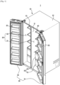
- FIG. 1 shows a refrigerator, according to an embodiment of the disclosure.
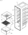
- FIG. 2 is an exploded view of a refrigerator with drawers and a supporting frame separated therefrom.
- FIG. 3 is a front view of an inner case of the refrigerator shown in FIG. 1 .
- FIG. 4 is a side view of the refrigerator shown in FIG. 1 with a drawer and a supporting frame.
- FIG.5 is a cross-sectional view of the refrigerator shown in FIG. 1 along line A-A' of FIG. 4 .
- FIG. 6 is an enlarged view of portion X of FIG. 5 .
- a refrigerator 1 includes a main body 10, a storeroom 20 with the front open, which is provided inside the main body 10, and a door 30 rotationally coupled to the main body 10 to open or close the open front of the storeroom 20.
- the main body 10 includes an inner case 11 defining the storeroom 20, an outer case 12 defining the exterior, and may include a cold air supply (not shown) for supplying cold air to the storeroom 20.
- the cold air supply may include a compressor, a condenser, an expansion valve, an evaporator, a fan, a cold air duct, etc., and insulation (not shown) is foamed between the inner case 11 and the outer case 12 of the main body 10 to prevent cold air from leaking out.
- the storeroom 20 is divided by a partition wall 13 into a fridge chamber 21 and a freezer chamber 22.
- the fridge chamber 21 and the freezer chamber 22 may be opened or closed by a fridge door 31 and a freezer door 32, respectively, which are rotationally coupled to the main body 10, and a plurality of door guards 35 may be installed on the rear sides of the door 30 to contain foods.
- One or more drawers 50 are detachably arranged in the storeroom 20.
- the drawer 50 may make an accommodating room to keep groceries inside, and may be arranged in a lower portion of the fridge chamber 21 or the freezer chamber 22 to be inserted thereto or pulled out therefrom.
- a supporting frame 100 is arranged in the storeroom 20 to support the drawer 50 and guide movements of the drawer 50.
- the supporting frame 100 may be inserted to the storeroom 20 through the open front of the storeroom 20 to be placed in the storeroom 20.
- the drawer 50 and the supporting frame 100 of the fridge chamber 21 will now be described in detail. The description may be equally applied to the freezer chamber 22.
- first drawer 51 and a second drawer 52 arranged above the first drawer 51 are shown in the fridge chamber 21 of the refrigerator 1 shown in FIG. 1 , embodiments of the disclosure are not limited thereto and there may be the first drawer 51 only or three or more drawers 50 arranged.
- a projection 14 is formed on a side of the inner case 11 that defines the fridge chamber 21.
- the projection 14 may be integrally formed with the inner case 11.
- the projection 14 includes a plurality of projections 14, and the second drawer 52 may slide into an installation groove 15 formed by the plurality of projections 14.
- the refrigerator 1 may include the supporting frame 100 arranged in the fridge chamber 21.
- the supporting frame 100 may be arranged between the first drawer 51 and the second drawer 52 to support the first drawer 51 and the second drawer 52.
- the first drawer 51 may be slidably coupled with the supporting frame 100.
- the supporting frame 100 may be detachably arranged in the fridge chamber 21.
- the supporting frame 100 is inserted to and detachably installed in the installation groove 15 formed by the plurality of projections 14, and both side edges of the supporting frame 100 are supported by the projections 14.
- a first guide rib 102 is inserted to the installation groove 15 so that the supporting frame 100 may be installed at the projection 14, in which case the projections 14 may be placed above and underneath the first guide rib 102.
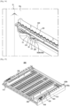
- FIG. 7 shows a supporting frame equipped in the refrigerator shown in FIG. 1 .
- FIG. 8 is a side view of the supporting frame shown in FIG. 7 .
- FIG. 9 is a bottom perspective view of the supporting frame shown in FIG. 7 .
- FIG. 10 is an enlarged view of portion B of FIG. 9 .
- the supporting frame 100 may include a main body 101, includes first guide ribs 102, and and may include a second guide rib 103.
- the main body 101 may be provided as a plate shaped member, and may have a plurality of holes 101a formed to have sufficient strength while saving materials required to manufacture the main body 101.
- the first guide rib 102 includes a plurality of first guide ribs 102.
- the first guide rib 102 may be formed to extend downwards from the main body 101 at both sides of the main body 101.
- the first guide rib 102 may be formed at edges of either side of the main body 101 to extend downwards.
- the first guide rib 102 may be integrally formed with the main body 101. Specifically, a first portion 102a of the first guide rib 102 may correspond to a side surface of the main body 101.
- the first guide rib 102 may include the first portion 102a vertically protruding from the horizontal main body 101, and a second portion 102b extending from the end of the first portion 102a to be parallel to the main body 101.
- the first portion 102a and the second portion 102b may be integrally formed.
- the first guide rib 102 may form a guide groove 102c to which the first drawer 51 may be inserted.
- the guide groove 102c may include a space surrounded by the main body 101, the first portion 102a, and the second portion 102b. Top edges of the first drawer 51 may be slidably inserted to the guide groove 102c, making the first drawer 51 slidably coupled with the supporting frame 100.
- guide rails 51a formed to extend sideways from the first drawer 51 may be arranged on top left and top right edges of the first drawer 51, and the guide rail 51a may be slidably inserted to the guide groove 102c.
- the guide rail 51a may be integrally formed with an accommodating portion 51b of the first drawer 51, which defines an accommodating room.
- the first drawer 51 may be prevented from trembling from side to side while the first drawer 51 is sliding into the guide groove 102c.
- the second guide rib 103 may include a plurality of second guide ribs 103, which may protrude upwards from the top surface of the main body 101. Specifically, the second guide rib 103 may be formed to protrude upwards from the top surface of the main body 101 on both sides of the main body 101.
- the second drawer 52 may be arranged to be put in or pulled out as a guide rail 52a formed on a lower portion of an accommodating portion 52b is inserted to the installation groove 15 formed by the projection 14.
- a supporting rib 52c protruding downwards from the guide rail 52a may be formed at the guide rail 52a.
- the second guide rib 103 may come into contact with the supporting rib 52c from the lower portion of the side of the second drawer 52, and thus support the lower portion of the side of the second drawer 52. Accordingly, the second guide rib 103 may prevent the second drawer 52 from trembling from side to side while the second drawer 52 is put in or pulled out.
- the supporting rib 52c may be omitted from the second drawer 52, and the second guide rib 103 may contact the lower portion of the side of the accommodating portion 52b of the second drawer 52 to support the second drawer 52.
- An elastic supporter 104 which is elastically deformable, may be arranged on a side of the main body 101 of the supporting frame 100.
- the elastic supporter 104 may include a plurality of elastic supporters 104.
- the elastic supporter 104 may be formed of an elastic material such as a synthetic resin.
- the elastic supporter 104 may be integrally formed with the main body 101.
- the elastic supporter 104 and the main body 101 may be formed of the elastic material.
- Separation slits 105 may be formed above and underneath the elastic supporter 104 to separate the elastic supporter 104 from the side of the main body 101. Left and right of the elastic supporter 104 may be connected to the side of the main body 101.
- the elastic supporter 104 While no external force is applied to the elastic supporter 104 (hereinafter, referred to as a non-pressurized sate), the elastic supporter 104 may protrude sideways from the main body 101 of the supporting frame 100.
- the elastic supporter 104 comes into contact with a side 11a of the inner case 11 and may be in a state of being pressurized by the side 11a of the inner case 11 (hereinafter, referred to as a pressurized state).
- the elastic supporter 104 may protrude sideways from the main body 101 less than in the non-pressurized state. In other words, it is pressurized by the side 11a of the inner case 11 and may be elastically deformed in the left and right direction.
- the elastically deformed elastic supporter 104 in the pressurized state may exert restitution force to the side 11a of the inner case 11 to be restored back into the non-pressurized state. Furthermore, even when a crack is made due to a gap between a side of the main body 101 and the side 11a of the inner case 11 or trembling of the supporting frame 100, the elastic supporter 104 in the pressurized state may be elastically restored as much as the width of the crack, keeping contact with the side 11a of the inner case 11. Accordingly, left or right movements of the supporting frame 100 may be prevented, and the supporting frame 100 may be stably supported.
- the supporting frame 100 may include a stopper 106.
- the stopper 106 may be formed to protrude from the top of the main body 101 of the supporting frame 100.
- the stopper 106 may restrict movement radius of the second drawer 52.
- a stopping projection 52d may be formed at the guide rail 52a of the second drawer 52 to correspond to the stopper 106, and movements of the stopping projection 52d may be restricted by the stopper 106.
- the guide rail 52a and the stopping projection 52d may be integrally formed.
- the stopping projection 52d may be put in or pulled out in sync with the second drawer 52, but when the second drawer 52 is pulled out beyond a certain range, the stopping projection 52d is interfered by the stopper 106, thereby restricting the movement range of the second drawer 52. Accordingly, the second drawer 52 may be prevented from being overly pulled out and deviating from the installation groove 15.
- the supporting frame 100 includes fixers 110 arranged on either side of the supporting frame 100 to prevent the supporting frame 100 from deviating from the projection 14.
- the fixer 110 includes a plurality of fixers 110.
- the fixer 110 is formed on the bottom surface of the first guide rib 102.
- the bottom surface of the first guide rib 102 may be formed by the second portion 102b, and the fixer 110 may be formed on the second portion 102b.
- the fixer 110 may be formed such that only a portion of the fixer 110 may be connected to the second portion 102b and the remaining portions may be separated from the second portion 102b. More specifically, the fixer 110 may be separated from the first guide rib 102 by a cut 107 formed between the fixer 110 and the first guide rib 102, and only one end of the fixer 110 may be connected to the first guide rib 102.
- the fixer 110 may include an insertion projection 111 arranged to be separated from the first guide rib 102, and an elastic connector 112 connecting between the first rib 102 and the insertion projection 111.
- the insertion projection 111 may have a triangular shape with a slope 111a, but it is not limited thereto and it may have a curve.
- the insertion projection 111 may protrude farther down than the second portion 102b of the first guide rib 102.
- the elastic connector 112 may have one end connected to the insertion projection 111 and the other end connected to the first guide rib 102.
- the elastic connector 112 may be formed of an elastic material such as a synthetic resin. Accordingly, when the insertion projection 111 is changed in position with respect to the first guide rib 102, the elastic connector 112 may be elastically deformed.
- the insertion projection 111 and the elastic connector 112 may be integrally formed.
- the insertion projection 111, the elastic connector 112, and the first guide rib 102 may be integrally formed.
- the insertion projection 111, the elastic connector 112, and the first guide rib 102 may be integrally formed of an elastic material.
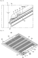
- FIG. 11 shows the portion B of the supporting frame of FIG. 9 being inserted to an installation groove.
- FIG. 12 shows a state in which the fixer of the supporting frame of FIG. 11 is inserted to a fixing groove.
- the supporting frame 100 is installed at the projection 14.
- the supporting frame 100 is inserted to and detachably installed in the installation groove 15 formed by the projection 14.
- the supporting frame 100 is fixed by the fixer 110 not to be deviated from the projection 14.
- the fixer 110 is inserted to a fixing groove 16 formed at the projection 14, so that the supporting frame 100 is installed at the projection 14. Specifically, the insertion projection 111 of the fixer 110 may be inserted to the fixing groove 16.
- the fixer 110 While no external force is applied to the fixer 110 (in the non-pressurized state), the fixer 110 may be located side by side with the second portion 102b of the first guide rib 102. Specifically, the elastic connector 112 of the fixer 110 may be located on the same plane with the second portion 102b of the first guide rib 102, and the insertion projection 111 of the fixer 110 may protrude farther down than the second portion 102b of the first guide rib 102.
- a portion of the projection 14 pressurizes the fixer 110.
- the portion of the projection 14 may pressurize the insertion projection 111 so that the insertion projection 111 is moved from the downward direction to the upward direction.
- the supporting frame 100 being pushed into the installation groove 15 to be installed therein may be inserted into the installation groove 15 without being interfered by the insertion projection 111, so that the supporting frame 100 may be easily installed.
- the elastic connector 112 may be elastically deformed.
- the elastic connector 112 which stays as a flat plate in the non-pressurized state, may bend according to a change in position of the insertion projection 111 connected to an end of the elastic connector 112. More specifically, as the elastic connector 112 has one end connected to the insertion projection 111 and the other end connected to the second portion 102b of the first guide rib 102, the elastic connector 112 in the pressurized state may be elastically deformed such that the one end comes above the second portion 102b.
- FIG. 13 is an enlarged view of a fixer of a supporting frame of a refrigerator according to claim 1, according to another embodiment of the disclosure.
- FIG. 14 shows a state in which the fixer of the supporting frame of FIG. 13 is inserted to a fixing groove. Descriptions of parts overlapping the foregoing will not be repeated.
- the fixing groove 16 is formed at the projection 14 in a position that corresponds to the fixer 110.
- the fixing groove 16 may be formed in a position where the insertion projection 111 is placed when the supporting frame 100 is fully inserted and installed. Accordingly, when the supporting frame 100 is pushed into the installation groove 15 in the pressurized state and fully inserted to and installed at the installation groove 15, the fixing groove 16 formed at the projection 14 may come under the insertion projection 111.
- the insertion projection 111 When the insertion projection 111 is located above the fixing groove 16, the insertion projection 111 is not in contact with the projection 14 that has been pushed the insertion projection 111, and the pressure from the projection 14 is released. Once the pressure from the projection 14 is released, the elastic connector 112 that has been in an elastically deformed state may be restored into its original state according to restitution force.
- the elastic connector 112 may be elastically restored such that one end of the elastic connector 112, which has been above the second portion 102b along with the insertion projection 111 in the pressurized state, may be located back on the same plane with the second portion 102b. That is, it may be restored back into the non-pressurized state.
- the insertion projection 111 of the fixer 110 restored into the non-pressurized stat may protrude farther down than the second portion 102b and may be inserted to the fixing groove 16 located underneath it. Accordingly, the fixer 110 fixes the supporting frame 100 to the projection 14 to prevent the supporting frame 100 from easily deviating from the projection 14.
- FIG. 15 is a perspective view of a supporting frame of a refrigerator in accordance with claim 1, according to another embodiment of the disclosure.
- FIG. 16 shows a state in which a fixer of the supporting frame of FIG. 15 is inserted to a fixing groove.
- the projection 14 arranged underneath the supporting frame 300 is not shown. Descriptions of parts overlapping the foregoing will not be repeated.
- the fixer 110 protrudes upwards from a supporting frame 300.
- the first guide rib 102 on which the fixer 110 is formed may be formed to protrude upwards from the main body 101 at either side edge of the main body 101.
- the first guide rib 102 may include the first portion 102a vertically protruding upwards from the horizontal main body 101, and the second portion 102b extending from the end of the first portion 102a to be parallel to the main body 101.
- the second portion 102b may correspond to the top surface of the first guide rib 102.
- the fixer 110 may be formed on the second portion 102b, and the insertion projection 111 of the fixer 110 may protrude farther up than the second portion 102b of the first guide rib 102.
- the supporting frame 300 may include a third guide rib 113 that may guide the first drawer 51.
- the third guide rib 113 may be formed to extend downwards from the bottom of the main body 300.
- the fixing groove 16 formed at the projection 14 may come above the insertion projection 111.
- the insertion projection 111 of the fixer 110 restored into the non-pressurized state may protrude farther up than the second portion 102b and may be inserted to the fixing groove 16 located above.
- FIG. 17 is a perspective view of a supporting frame of a refrigerator in accordance with claim 1, according to another embodiment of the disclosure.
- FIG. 18 is an enlarged view of portion X' of FIG. 17 .Descriptions of parts overlapping the foregoing will not be repeated.
- the fixer 110 protrudes upwards from a supporting frame 400.
- the fixer 110 may be arranged on either side of a top surface 100b of the main body 101 to protrude upwards from the main body 101, and may be located between the first guide rib 102 and the second guide rib 103.
- the insertion projection 111 of the fixer 110 may protrude farther up than the top surface 100b of the main body 101.
- a portion of the top surface 100b of the main body 101, on which the fixer 110 is formed, may be formed to be flat.
- the fixing groove 16 formed at the projection 14 may come above the insertion projection 111.
- the insertion projection 111 of the fixer 110 restored into the non-pressurized state may protrude upwards from the main body 101 and may be inserted to the fixing groove 16 located above.
- a supporting frame supports a drawer and guides movements of the drawer, so that trembling of the drawer may be reduced and noise occurring when the drawer collides with an inner case may be reduced.
- the supporting frame is equipped with an elastically deformable fixer, by which the supporting frame may be easily inserted and fixed to a projection formed at the inner case.
Landscapes
- Engineering & Computer Science (AREA)
- Chemical & Material Sciences (AREA)
- Combustion & Propulsion (AREA)
- Physics & Mathematics (AREA)
- Mechanical Engineering (AREA)
- Thermal Sciences (AREA)
- General Engineering & Computer Science (AREA)
- Refrigerator Housings (AREA)
Description
- The disclosure relates to a refrigerator, and more particularly, to a refrigerator having a supporting frame whose installation structure is enhanced.
- Refrigerators are devices having a storeroom and a cold air supply for supplying cold air into the storeroom to keep groceries fresh.
- Temperatures in the storeroom remain within a certain range required to keep the groceries fresh.
- The storeroom has an open front, which is closed by a door at ordinary times to maintain the temperature of the storeroom.
- The storeroom is partitioned by a wall into a freezer chamber and a fridge chamber, the freezer and fridge chambers being opened or closed by the respective doors.
- There are drawers detachably arranged in the fridge and freezer chambers to make accommodating rooms to keep groceries, and the drawers may be inserted to or pulled out from the fridge and freezer chambers.
- The drawer is formed as a separate part from an inner case that defines the storeroom, so the drawer may be trembled from side to side, making noise while inserted to or pulled out from the storeroom.
KR 2009 0133009 A US 2016/178274 A1 discloses a refrigerator which includes a drawer possessing a locking mechanism.KR 102 034 293 B1 - Further relevant prior art is disclosed in document
CN107144083A . - The disclosure provides a refrigerator equipped with a supporting frame to reduce trembling and noise occurring from a drawer when the drawer is inserted or pulled out.
- The disclosure also provides a refrigerator equipped with a supporting frame having an enhanced installation structure to be easily installed in a storeroom.
- According to the invention, there is provided a refrigerator according to
claim 1. Preferred features are set out in the dependent claims. - A supporting frame supports a drawer and guides movements of the drawer, so that trembling of the drawer may be reduced and noise occurring when the drawer collides with an inner case may be reduced.
- The supporting frame is equipped with an elastically deformable fixer, by which the supporting frame may be easily inserted and fixed to a projection formed at the inner case.
-
-
FIG. 1 shows a refrigerator, according to an embodiment of the invention. -
FIG. 2 is an exploded view of the refrigerator shown inFIG. 1 with drawers and a supporting frame separated therefrom; -
FIG. 3 is a front view of an inner case of the refrigerator shown inFIG. 1 ; -
FIG. 4 is a side view of the refrigerator shown inFIG. 1 with a drawer and a supporting frame; -
FIG.5 is a cross-sectional view of the refrigerator shown inFIG. 1 along line A-A' ofFIG. 4 ; -
FIG. 6 is an enlarged view of portion X ofFIG. 5 ; -
FIG. 7 shows a supporting frame equipped in the refrigerator shown inFIG. 1 ; -
FIG. 8 is a side view of the supporting frame shown inFIG. 7 ; -
FIG. 9 is a bottom perspective view of the supporting frame shown inFIG. 7 ; -
FIG. 10 is an enlarged view of portion B ofFIG. 9 ; -
FIG. 11 shows the portion B of the supporting frame ofFIG. 9 being inserted to an installation groove; -
FIG. 12 shows a state in which a fixer of the supporting frame ofFIG. 11 is inserted to a fixing groove; -
FIG. 13 is an enlarged view of a fixer of a supporting frame of a refrigerator, according to another embodiment of the invention. -
FIG. 14 shows a state in which the fixer of the supporting frame ofFIG. 13 is inserted to a fixing groove; -
FIG. 15 is a perspective view of a supporting frame of a refrigerator, according to another embodiment of the invention. -
FIG. 16 shows a state in which a fixer of the supporting frame ofFIG. 15 is inserted to a fixing groove; -
FIG. 17 is a perspective view of a supporting frame of a refrigerator, according to another embodiment of the invention. -
FIG. 18 is an enlarged view of portion X' ofFIG. 17 . - Throughout the drawings, like reference numerals refer to like parts or components. For the sake of clarity, the elements of the drawings are drawn with exaggerated forms and sizes.
- The terminology used herein is for the purpose of describing particular embodiments only and is not intended to limit the present disclosure. It is to be understood that the singular forms "a," "'an," and "the" include plural references unless the context clearly dictates otherwise.
- It will be further understood that the terms "comprise" and/or "comprising," when used in this specification, specify the presence of stated features, integers, steps, operations, elements, and/or components, but do not preclude the presence or addition of one or more other features, integers, steps, operations, elements, components, and/or groups thereof.
- The terms including ordinal numbers like "first" and "second" may be used to explain various components, but the components are not limited by the terms. The terms are only for the purpose of distinguishing a component from another. Thus, a first element, component, region, layer or chamber discussed below could be termed a second element, component, region, layer or section without departing from the teachings of the disclosure. Descriptions shall be understood as to include any and all combinations of one or more of the associated listed items when the items are described by using the conjunctive term "~ and/or ~," or the like.
- The terms "front", "rear", "upper", "lower", "top", and "bottom" as herein used are defined with respect to the drawings, but the terms may not restrict the shape and position of the respective components.
- The disclosure provides a refrigerator equipped with a supporting frame to reduce trembling and noise occurring from a drawer when the drawer is inserted or pulled out.
- The disclosure also provides a refrigerator equipped with a supporting frame having an enhanced installation structure to be easily installed in a storeroom.
- Reference will now be made in detail to embodiments of the disclosure, which are illustrated in the accompanying drawings, wherein like reference numerals refer to the like elements throughout.
-
FIG. 1 shows a refrigerator, according to an embodiment of the disclosure.FIG. 2 is an exploded view of a refrigerator with drawers and a supporting frame separated therefrom.FIG. 3 is a front view of an inner case of the refrigerator shown inFIG. 1 .FIG. 4 is a side view of the refrigerator shown inFIG. 1 with a drawer and a supporting frame.FIG.5 is a cross-sectional view of the refrigerator shown inFIG. 1 along line A-A' ofFIG. 4 .FIG. 6 is an enlarged view of portion X ofFIG. 5 . - Referring to
FIGS. 1 to 6 , arefrigerator 1 according toclaim 1 includes amain body 10, astoreroom 20 with the front open, which is provided inside themain body 10, and adoor 30 rotationally coupled to themain body 10 to open or close the open front of thestoreroom 20. - The
main body 10 includes aninner case 11 defining thestoreroom 20, anouter case 12 defining the exterior, and may include a cold air supply (not shown) for supplying cold air to thestoreroom 20. - The cold air supply may include a compressor, a condenser, an expansion valve, an evaporator, a fan, a cold air duct, etc., and insulation (not shown) is foamed between the
inner case 11 and theouter case 12 of themain body 10 to prevent cold air from leaking out. - The
storeroom 20 is divided by apartition wall 13 into afridge chamber 21 and afreezer chamber 22. Thefridge chamber 21 and thefreezer chamber 22 may be opened or closed by afridge door 31 and afreezer door 32, respectively, which are rotationally coupled to themain body 10, and a plurality ofdoor guards 35 may be installed on the rear sides of thedoor 30 to contain foods. - There may be a plurality of
racks 40 provided in thestoreroom 20, which may divide thefridge chamber 21 andfreezer chamber 22 into a plurality of spaces. - One or
more drawers 50 are detachably arranged in thestoreroom 20. Thedrawer 50 may make an accommodating room to keep groceries inside, and may be arranged in a lower portion of thefridge chamber 21 or thefreezer chamber 22 to be inserted thereto or pulled out therefrom. - A supporting
frame 100 is arranged in thestoreroom 20 to support thedrawer 50 and guide movements of thedrawer 50. The supportingframe 100 may be inserted to thestoreroom 20 through the open front of thestoreroom 20 to be placed in thestoreroom 20. - The
drawer 50 and the supportingframe 100 of thefridge chamber 21 will now be described in detail. The description may be equally applied to thefreezer chamber 22. - Although a
first drawer 51 and asecond drawer 52 arranged above thefirst drawer 51 are shown in thefridge chamber 21 of therefrigerator 1 shown inFIG. 1 , embodiments of the disclosure are not limited thereto and there may be thefirst drawer 51 only or three ormore drawers 50 arranged. - A
projection 14 is formed on a side of theinner case 11 that defines thefridge chamber 21. Theprojection 14 may be integrally formed with theinner case 11. Theprojection 14 includes a plurality ofprojections 14, and thesecond drawer 52 may slide into aninstallation groove 15 formed by the plurality ofprojections 14. - The
refrigerator 1 may include the supportingframe 100 arranged in thefridge chamber 21. - The supporting
frame 100 may be arranged between thefirst drawer 51 and thesecond drawer 52 to support thefirst drawer 51 and thesecond drawer 52. Thefirst drawer 51 may be slidably coupled with the supportingframe 100. - The supporting
frame 100 may be detachably arranged in thefridge chamber 21. The supportingframe 100 is inserted to and detachably installed in theinstallation groove 15 formed by the plurality ofprojections 14, and both side edges of the supportingframe 100 are supported by theprojections 14. Specifically, afirst guide rib 102 is inserted to theinstallation groove 15 so that the supportingframe 100 may be installed at theprojection 14, in which case theprojections 14 may be placed above and underneath thefirst guide rib 102. -
FIG. 7 shows a supporting frame equipped in the refrigerator shown inFIG. 1 .FIG. 8 is a side view of the supporting frame shown inFIG. 7 .FIG. 9 is a bottom perspective view of the supporting frame shown inFIG. 7 .FIG. 10 is an enlarged view of portion B ofFIG. 9 . - Referring to
FIGS. 6 to 10 , the supportingframe 100 may include amain body 101, includesfirst guide ribs 102, and and may include asecond guide rib 103. - The
main body 101 may be provided as a plate shaped member, and may have a plurality ofholes 101a formed to have sufficient strength while saving materials required to manufacture themain body 101. - The
first guide rib 102 includes a plurality offirst guide ribs 102. Thefirst guide rib 102 may be formed to extend downwards from themain body 101 at both sides of themain body 101. Thefirst guide rib 102 may be formed at edges of either side of themain body 101 to extend downwards. Thefirst guide rib 102 may be integrally formed with themain body 101. Specifically, afirst portion 102a of thefirst guide rib 102 may correspond to a side surface of themain body 101. - The
first guide rib 102 may include thefirst portion 102a vertically protruding from the horizontalmain body 101, and asecond portion 102b extending from the end of thefirst portion 102a to be parallel to themain body 101. Thefirst portion 102a and thesecond portion 102b may be integrally formed. - The
first guide rib 102 may form aguide groove 102c to which thefirst drawer 51 may be inserted. Specifically, theguide groove 102c may include a space surrounded by themain body 101, thefirst portion 102a, and thesecond portion 102b. Top edges of thefirst drawer 51 may be slidably inserted to theguide groove 102c, making thefirst drawer 51 slidably coupled with the supportingframe 100. - More specifically,
guide rails 51a formed to extend sideways from thefirst drawer 51 may be arranged on top left and top right edges of thefirst drawer 51, and theguide rail 51a may be slidably inserted to theguide groove 102c. Theguide rail 51a may be integrally formed with anaccommodating portion 51b of thefirst drawer 51, which defines an accommodating room. - As the
guide rail 51a is stably supported by thefirst guide rib 102, thefirst drawer 51 may be prevented from trembling from side to side while thefirst drawer 51 is sliding into theguide groove 102c. - The
second guide rib 103 may include a plurality ofsecond guide ribs 103, which may protrude upwards from the top surface of themain body 101. Specifically, thesecond guide rib 103 may be formed to protrude upwards from the top surface of themain body 101 on both sides of themain body 101. - The
second drawer 52 may be arranged to be put in or pulled out as aguide rail 52a formed on a lower portion of anaccommodating portion 52b is inserted to theinstallation groove 15 formed by theprojection 14. A supportingrib 52c protruding downwards from theguide rail 52a may be formed at theguide rail 52a. Thesecond guide rib 103 may come into contact with the supportingrib 52c from the lower portion of the side of thesecond drawer 52, and thus support the lower portion of the side of thesecond drawer 52. Accordingly, thesecond guide rib 103 may prevent thesecond drawer 52 from trembling from side to side while thesecond drawer 52 is put in or pulled out. - However, it is not limited thereto. The supporting
rib 52c may be omitted from thesecond drawer 52, and thesecond guide rib 103 may contact the lower portion of the side of theaccommodating portion 52b of thesecond drawer 52 to support thesecond drawer 52. - An
elastic supporter 104, which is elastically deformable, may be arranged on a side of themain body 101 of the supportingframe 100. Theelastic supporter 104 may include a plurality ofelastic supporters 104. Theelastic supporter 104 may be formed of an elastic material such as a synthetic resin. Theelastic supporter 104 may be integrally formed with themain body 101. Theelastic supporter 104 and themain body 101 may be formed of the elastic material. - Separation slits 105 may be formed above and underneath the
elastic supporter 104 to separate theelastic supporter 104 from the side of themain body 101. Left and right of theelastic supporter 104 may be connected to the side of themain body 101. - While no external force is applied to the elastic supporter 104 (hereinafter, referred to as a non-pressurized sate), the
elastic supporter 104 may protrude sideways from themain body 101 of the supportingframe 100. - When the supporting
frame 100 is inserted to theinstallation groove 15, theelastic supporter 104 comes into contact with aside 11a of theinner case 11 and may be in a state of being pressurized by theside 11a of the inner case 11 (hereinafter, referred to as a pressurized state). - In the pressurized state, the
elastic supporter 104 may protrude sideways from themain body 101 less than in the non-pressurized state. In other words, it is pressurized by theside 11a of theinner case 11 and may be elastically deformed in the left and right direction. - The elastically deformed
elastic supporter 104 in the pressurized state may exert restitution force to theside 11a of theinner case 11 to be restored back into the non-pressurized state. Furthermore, even when a crack is made due to a gap between a side of themain body 101 and theside 11a of theinner case 11 or trembling of the supportingframe 100, theelastic supporter 104 in the pressurized state may be elastically restored as much as the width of the crack, keeping contact with theside 11a of theinner case 11. Accordingly, left or right movements of the supportingframe 100 may be prevented, and the supportingframe 100 may be stably supported. - The supporting
frame 100 may include astopper 106. Thestopper 106 may be formed to protrude from the top of themain body 101 of the supportingframe 100. - The
stopper 106 may restrict movement radius of thesecond drawer 52. Specifically, a stoppingprojection 52d may be formed at theguide rail 52a of thesecond drawer 52 to correspond to thestopper 106, and movements of the stoppingprojection 52d may be restricted by thestopper 106. Theguide rail 52a and the stoppingprojection 52d may be integrally formed. - More specifically, the stopping
projection 52d may be put in or pulled out in sync with thesecond drawer 52, but when thesecond drawer 52 is pulled out beyond a certain range, the stoppingprojection 52d is interfered by thestopper 106, thereby restricting the movement range of thesecond drawer 52. Accordingly, thesecond drawer 52 may be prevented from being overly pulled out and deviating from theinstallation groove 15. - The supporting
frame 100 includesfixers 110 arranged on either side of the supportingframe 100 to prevent the supportingframe 100 from deviating from theprojection 14. Thefixer 110 includes a plurality offixers 110. - The
fixer 110 is formed on the bottom surface of thefirst guide rib 102. Specifically, the bottom surface of thefirst guide rib 102 may be formed by thesecond portion 102b, and thefixer 110 may be formed on thesecond portion 102b. Thefixer 110 may be formed such that only a portion of thefixer 110 may be connected to thesecond portion 102b and the remaining portions may be separated from thesecond portion 102b. More specifically, thefixer 110 may be separated from thefirst guide rib 102 by acut 107 formed between thefixer 110 and thefirst guide rib 102, and only one end of thefixer 110 may be connected to thefirst guide rib 102. - The
fixer 110 may include aninsertion projection 111 arranged to be separated from thefirst guide rib 102, and anelastic connector 112 connecting between thefirst rib 102 and theinsertion projection 111. - The
insertion projection 111 may have a triangular shape with aslope 111a, but it is not limited thereto and it may have a curve. Theinsertion projection 111 may protrude farther down than thesecond portion 102b of thefirst guide rib 102. - The
elastic connector 112 may have one end connected to theinsertion projection 111 and the other end connected to thefirst guide rib 102. Theelastic connector 112 may be formed of an elastic material such as a synthetic resin. Accordingly, when theinsertion projection 111 is changed in position with respect to thefirst guide rib 102, theelastic connector 112 may be elastically deformed. - The
insertion projection 111 and theelastic connector 112 may be integrally formed. Theinsertion projection 111, theelastic connector 112, and thefirst guide rib 102 may be integrally formed. Theinsertion projection 111, theelastic connector 112, and thefirst guide rib 102 may be integrally formed of an elastic material. -
FIG. 11 shows the portion B of the supporting frame ofFIG. 9 being inserted to an installation groove.FIG. 12 shows a state in which the fixer of the supporting frame ofFIG. 11 is inserted to a fixing groove. - Referring to
FIGS. 3 ,11 and12 , the supportingframe 100 is installed at theprojection 14. The supportingframe 100 is inserted to and detachably installed in theinstallation groove 15 formed by theprojection 14. When the supportingframe 100 is installed in theinstallation groove 15, the supportingframe 100 is fixed by thefixer 110 not to be deviated from theprojection 14. - The
fixer 110 is inserted to a fixinggroove 16 formed at theprojection 14, so that the supportingframe 100 is installed at theprojection 14. Specifically, theinsertion projection 111 of thefixer 110 may be inserted to the fixinggroove 16. - While no external force is applied to the fixer 110 (in the non-pressurized state), the
fixer 110 may be located side by side with thesecond portion 102b of thefirst guide rib 102. Specifically, theelastic connector 112 of thefixer 110 may be located on the same plane with thesecond portion 102b of thefirst guide rib 102, and theinsertion projection 111 of thefixer 110 may protrude farther down than thesecond portion 102b of thefirst guide rib 102. - When the supporting
frame 100 is pushed into theinstallation groove 15 to install the supportingframe 110 at theprojection 14, a portion of theprojection 14 pressurizes thefixer 110. In particular, the portion of theprojection 14 may pressurize theinsertion projection 111 so that theinsertion projection 111 is moved from the downward direction to the upward direction. - While the
insertion projection 111 is pressurized by the projection 14 (in the pressurized state), theinsertion projection 111 is in a position different from when it is in the non-pressurized state, with respect to thesecond portion 102b of thefirst guide rib 102. Specifically, as theinsertion projection 111 is pushed upwards, theinsertion projection 111 in the pressurized state has a smaller portion than in the non-pressurized state, which protrudes farther down than thesecond portion 102b or may not protrude farther down than thesecond portion 102b. - Accordingly, the supporting
frame 100 being pushed into theinstallation groove 15 to be installed therein may be inserted into theinstallation groove 15 without being interfered by theinsertion projection 111, so that the supportingframe 100 may be easily installed. - In the pressurized state, the
elastic connector 112 may be elastically deformed. Specifically, theelastic connector 112, which stays as a flat plate in the non-pressurized state, may bend according to a change in position of theinsertion projection 111 connected to an end of theelastic connector 112. More specifically, as theelastic connector 112 has one end connected to theinsertion projection 111 and the other end connected to thesecond portion 102b of thefirst guide rib 102, theelastic connector 112 in the pressurized state may be elastically deformed such that the one end comes above thesecond portion 102b. - As shown in
FIG. 11 , theelastic connector 112 may be located behind theinsertion projection 111 to connect theinsertion projection 111 to thesecond portion 102b of the first guide rib 102.However, it is not limited thereto. -
FIG. 13 is an enlarged view of a fixer of a supporting frame of a refrigerator according toclaim 1, according to another embodiment of the disclosure.FIG. 14 shows a state in which the fixer of the supporting frame ofFIG. 13 is inserted to a fixing groove. Descriptions of parts overlapping the foregoing will not be repeated. - Referring to
FIGS. 13 and14 , as in a supportingframe 200 shown inFIG. 13 , theelastic connector 112 may be located in front of theinsertion projection 111 to connect theinsertion projection 111 to thesecond portion 102b of thefirst guide rib 102. Besides, as will be described below, theelastic connector 112 may be arranged in any position at which to deliver restitution force to theinsertion projection 111. - The following description may be equally applied to the supporting
frame 200 shown inFIG. 13 . - Turning back to
FIGS. 3 ,11 and12 , the fixinggroove 16 is formed at theprojection 14 in a position that corresponds to thefixer 110. Specifically, the fixinggroove 16 may be formed in a position where theinsertion projection 111 is placed when the supportingframe 100 is fully inserted and installed. Accordingly, when the supportingframe 100 is pushed into theinstallation groove 15 in the pressurized state and fully inserted to and installed at theinstallation groove 15, the fixinggroove 16 formed at theprojection 14 may come under theinsertion projection 111. - When the
insertion projection 111 is located above the fixinggroove 16, theinsertion projection 111 is not in contact with theprojection 14 that has been pushed theinsertion projection 111, and the pressure from theprojection 14 is released. Once the pressure from theprojection 14 is released, theelastic connector 112 that has been in an elastically deformed state may be restored into its original state according to restitution force. - Specifically, the
elastic connector 112 may be elastically restored such that one end of theelastic connector 112, which has been above thesecond portion 102b along with theinsertion projection 111 in the pressurized state, may be located back on the same plane with thesecond portion 102b. That is, it may be restored back into the non-pressurized state. - In this case, the
insertion projection 111 connected to the restored end of theelastic connector 112 does not have theprojection 14 underneath it, and may thus be moved downwards along with the end of theelastic connector 112 and may protrude farther down than thesecond portion 102b. That is, theelastic connector 112 may be able to deliver restitution force to theinsertion projection 111, and thefixer 110 may go back into the non-pressurized stat. - The
insertion projection 111 of thefixer 110 restored into the non-pressurized stat may protrude farther down than thesecond portion 102b and may be inserted to the fixinggroove 16 located underneath it. Accordingly, thefixer 110 fixes the supportingframe 100 to theprojection 14 to prevent the supportingframe 100 from easily deviating from theprojection 14. - However, it is not limited thereto.
FIG. 15 is a perspective view of a supporting frame of a refrigerator in accordance withclaim 1, according to another embodiment of the disclosure.FIG. 16 shows a state in which a fixer of the supporting frame ofFIG. 15 is inserted to a fixing groove. InFIG. 16 , theprojection 14 arranged underneath the supportingframe 300 is not shown. Descriptions of parts overlapping the foregoing will not be repeated. - The
fixer 110 protrudes upwards from a supportingframe 300. Specifically, thefirst guide rib 102 on which thefixer 110 is formed may be formed to protrude upwards from themain body 101 at either side edge of themain body 101. - For example, the
first guide rib 102 may include thefirst portion 102a vertically protruding upwards from the horizontalmain body 101, and thesecond portion 102b extending from the end of thefirst portion 102a to be parallel to themain body 101. In this case, thesecond portion 102b may correspond to the top surface of thefirst guide rib 102. Thefixer 110 may be formed on thesecond portion 102b, and theinsertion projection 111 of thefixer 110 may protrude farther up than thesecond portion 102b of thefirst guide rib 102. - In this case, the supporting
frame 300 may include athird guide rib 113 that may guide thefirst drawer 51. Thethird guide rib 113 may be formed to extend downwards from the bottom of themain body 300. - When the supporting
frame 300 is pushed into theinstallation groove 15 in the pressurized state and fully inserted to and installed at theinstallation groove 15, the fixinggroove 16 formed at theprojection 14 may come above theinsertion projection 111. Theinsertion projection 111 of thefixer 110 restored into the non-pressurized state may protrude farther up than thesecond portion 102b and may be inserted to the fixinggroove 16 located above. - There may be another example.
FIG. 17 is a perspective view of a supporting frame of a refrigerator in accordance withclaim 1, according to another embodiment of the disclosure.FIG. 18 is an enlarged view of portion X' ofFIG. 17 .Descriptions of parts overlapping the foregoing will not be repeated. - The
fixer 110 protrudes upwards from a supportingframe 400. Specifically, thefixer 110 may be arranged on either side of a top surface 100b of themain body 101 to protrude upwards from themain body 101, and may be located between thefirst guide rib 102 and thesecond guide rib 103. - The
insertion projection 111 of thefixer 110 may protrude farther up than the top surface 100b of themain body 101. A portion of the top surface 100b of themain body 101, on which thefixer 110 is formed, may be formed to be flat. - When the supporting
frame 400 is pushed into theinstallation groove 15 in the pressurized state and fully inserted to and installed at theinstallation groove 15, the fixinggroove 16 formed at theprojection 14 may come above theinsertion projection 111. Theinsertion projection 111 of thefixer 110 restored into the non-pressurized state may protrude upwards from themain body 101 and may be inserted to the fixinggroove 16 located above. - A supporting frame supports a drawer and guides movements of the drawer, so that trembling of the drawer may be reduced and noise occurring when the drawer collides with an inner case may be reduced.
- The supporting frame is equipped with an elastically deformable fixer, by which the supporting frame may be easily inserted and fixed to a projection formed at the inner case.
- Several embodiments of the disclosure have been described above, but a person of ordinary skill in the art will understand and appreciate that various modifications can be made without departing the scope of the disclosure. Thus, it will be apparent to those ordinary skilled in the art that the true scope of technical protection is only defined by the following claims.
Claims (13)
- A refrigerator (1) comprising:an inner case (11) defining a storeroom (20) and having a plurality of projections (14) formed to protrude toward an inside of the storeroom (20);a drawer (50) arranged to be inserted into or pulled out from the storeroom (20); anda supporting frame (100) formed in a plate shape and formed to extend across a width of the drawer, the supporting frame (100) arranged to be installed at the projections (14) of the inner case (11) in the storeroom (20) to guide a movement of the drawer (50),wherein the supporting frame (100) comprises:guide ribs (102) formed to guide the movement of the drawer (50), anda plurality of fixers (110) arranged on both sides of the supporting frame (100) to prevent the supporting frame (100) from deviating from the projections (14), the fixers (110) being formed on bottom surfaces of the guide ribs (102) and being deformed from an original state when a pressure is applied by the projections (14) and restored to the original state when the pressure from the projections is released;wherein the supporting frame (100) is inserted to and installed in an installation groove (15) formed by the plurality of projections (14), and both side edges of the supporting frame (100) are supported by the projections (14), andcharacterized in thatthe projection (14) comprises a fixing groove (16) recessed to form a space into which the fixer (110) is insertable, and the supporting frame (100) is fixed to the projection (14) while the fixer (110) is inserted into the fixing groove (16).
- The refrigerator of claim 1,
wherein each fixer comprises an insertion projection (111) arranged to be separated from the guide rib by a cut, and an elastic connector (112) to connect the guide rib to the insertion projection (111). - The refrigerator of claim 2, wherein the elastic connector (112) is elastically deformed as the insertion projection is pushed upwards by the pressure applied from the projection (14), and restored to an original state of the elastic connector when the pressure from the projection is released.
- The refrigerator of claim 3, wherein the insertion projection (111) is inserted to the fixing groove.
- The refrigerator of claim 4, wherein the insertion projection is pushed upwards by the pressure from the projection, and when the insertion projection is located above the fixing groove, the pressure from the projection is released and the insertion projection is returned to an original state of the insertion projection and inserted to the fixing groove.
- The refrigerator of claim 4, wherein the insertion projection has a slope arranged to come into contact with the projection, and the projection pushes up the insertion projection while sliding on the slope.
- The refrigerator of claim 2, wherein the elastic connector (112) is formed behind the insertion projection (111).
- The refrigerator of claim 2, wherein the elastic connector (112) is formed in front of the insertion projection (111).
- The refrigerator of claim 1, wherein the supporting frame (100) comprises elastic supporters (104) to prevent the supporting frame from moving from side to side.
- The refrigerator of claim 2, wherein an upper portion of the drawer is slidably inserted to a guide groove formed by each guide rib.
- The refrigerator of claim 10, wherein the drawer is a first drawer (51) and the guide ribs are first guide ribs, and the refrigerator further comprises:
a second drawer arranged above the first drawer, and second guide ribs formed on the supporting frame to guide a movement of the second drawer. - The refrigerator of claim 11,wherein the supporting frame comprises a main body arranged between the first drawer and the second drawer, andwherein the first guide ribs are formed to protrude downwards from the main body, andthe second guide ribs are formed to protrude upwards from the main body.
- The refrigerator of claim 12, wherein each second guide rib supports a lower portion of a side of the second drawer to prevent the second drawer from moving from side to side.
Applications Claiming Priority (2)
| Application Number | Priority Date | Filing Date | Title |
|---|---|---|---|
| KR1020200013831A KR20210099904A (en) | 2020-02-05 | 2020-02-05 | Refrigerator |
| PCT/KR2021/001511 WO2021158050A1 (en) | 2020-02-05 | 2021-02-05 | Refrigerator |
Publications (4)
| Publication Number | Publication Date |
|---|---|
| EP4042080A1 EP4042080A1 (en) | 2022-08-17 |
| EP4042080A4 EP4042080A4 (en) | 2022-11-02 |
| EP4042080B1 true EP4042080B1 (en) | 2024-08-21 |
| EP4042080C0 EP4042080C0 (en) | 2024-08-21 |
Family
ID=77061390
Family Applications (1)
| Application Number | Title | Priority Date | Filing Date |
|---|---|---|---|
| EP21751147.6A Active EP4042080B1 (en) | 2020-02-05 | 2021-02-05 | Refrigerator |
Country Status (4)
| Country | Link |
|---|---|
| US (1) | US11629907B2 (en) |
| EP (1) | EP4042080B1 (en) |
| KR (1) | KR20210099904A (en) |
| WO (1) | WO2021158050A1 (en) |
Citations (1)
| Publication number | Priority date | Publication date | Assignee | Title |
|---|---|---|---|---|
| CN107144083A (en) * | 2017-05-24 | 2017-09-08 | 青岛海尔股份有限公司 | Refrigeration compartment and the refrigerator with it |
Family Cites Families (19)
| Publication number | Priority date | Publication date | Assignee | Title |
|---|---|---|---|---|
| KR900000704Y1 (en) | 1986-09-11 | 1990-01-30 | 삼성전자주식회사 | Rail for shelf of refrigerator |
| JP3294964B2 (en) | 1995-01-13 | 2002-06-24 | 三菱電機株式会社 | refrigerator |
| JPH11132649A (en) | 1997-10-31 | 1999-05-21 | Sanyo Electric Co Ltd | Refrigerator |
| KR100389639B1 (en) | 2001-01-31 | 2003-06-27 | 엘지전자 주식회사 | Cabinet fixing structure for tention rib |
| JP2005156133A (en) | 2003-10-31 | 2005-06-16 | Sanyo Electric Co Ltd | Refrigerator |
| KR101313552B1 (en) | 2007-02-26 | 2013-10-01 | 삼성전자주식회사 | Refrigerator |
| KR101554852B1 (en) * | 2008-03-06 | 2015-09-23 | 삼성전자 주식회사 | Refrigerator |
| KR20090133009A (en) | 2008-06-23 | 2009-12-31 | 엘지전자 주식회사 | Drawer of refrigerator |
| KR101427277B1 (en) | 2008-06-26 | 2014-08-06 | 엘지전자 주식회사 | Drawer mounting structure of refrigerator |
| CN102374747B (en) | 2011-11-21 | 2014-10-22 | 合肥美的电冰箱有限公司 | Refrigerator |
| KR102034293B1 (en) | 2012-12-10 | 2019-11-08 | 엘지전자 주식회사 | A refrigerator |
| KR102028022B1 (en) | 2013-04-05 | 2019-10-04 | 삼성전자주식회사 | Refrigerator |
| KR101641263B1 (en) | 2014-12-23 | 2016-07-20 | 엘지전자 주식회사 | Refrigerator |
| CN205174989U (en) * | 2015-10-30 | 2016-04-20 | 海信(山东)冰箱有限公司 | Refrigerator drawer guideway system and refrigerator |
| CN105466138B (en) | 2015-12-29 | 2019-01-18 | 青岛海尔股份有限公司 | Closed case assembly |
| KR102415750B1 (en) * | 2016-01-04 | 2022-07-01 | 엘지전자 주식회사 | Refrigerator |
| CH710199A1 (en) | 2016-02-01 | 2016-03-31 | V Zug Ag | Refrigeration device comprising at least one tray with spring element. |
| KR102500805B1 (en) | 2018-01-18 | 2023-02-17 | 엘지전자 주식회사 | refrigerator |
| KR20190088310A (en) | 2018-01-18 | 2019-07-26 | 엘지전자 주식회사 | refrigerator |
-
2020
- 2020-02-05 KR KR1020200013831A patent/KR20210099904A/en active Pending
-
2021
- 2021-02-05 WO PCT/KR2021/001511 patent/WO2021158050A1/en not_active Ceased
- 2021-02-05 EP EP21751147.6A patent/EP4042080B1/en active Active
- 2021-02-05 US US17/168,570 patent/US11629907B2/en active Active
Patent Citations (1)
| Publication number | Priority date | Publication date | Assignee | Title |
|---|---|---|---|---|
| CN107144083A (en) * | 2017-05-24 | 2017-09-08 | 青岛海尔股份有限公司 | Refrigeration compartment and the refrigerator with it |
Also Published As
| Publication number | Publication date |
|---|---|
| KR20210099904A (en) | 2021-08-13 |
| EP4042080A4 (en) | 2022-11-02 |
| US11629907B2 (en) | 2023-04-18 |
| EP4042080A1 (en) | 2022-08-17 |
| EP4042080C0 (en) | 2024-08-21 |
| US20210239390A1 (en) | 2021-08-05 |
| WO2021158050A1 (en) | 2021-08-12 |
Similar Documents
| Publication | Publication Date | Title |
|---|---|---|
| EP3809076B1 (en) | Refrigerator | |
| US9759479B2 (en) | Appliance modular system for incorporating a pantry compartment within an appliance | |
| KR102296461B1 (en) | Refrigerator | |
| US10006693B2 (en) | Appliance modular system for incorporating a pantry compartment within an appliance | |
| KR950019567A (en) | Capacity variable refrigerator | |
| US8911040B2 (en) | Refrigerator | |
| EP3109581A2 (en) | Refrigerator | |
| US20170191742A1 (en) | Refrigerator | |
| US5540492A (en) | Snap-in humidity control for crisper pans | |
| CA2014912C (en) | Refrigerator cabinet assembly | |
| CN112513546B (en) | Refrigerator with a door | |
| CN103608631B (en) | Refrigerating appliances with air channels | |
| US11629907B2 (en) | Refrigerator | |
| EP4249836B1 (en) | Refrigerator | |
| JP7755983B2 (en) | Refrigerator and refrigerator manufacturing method | |
| JP2021183903A (en) | refrigerator | |
| JP6407822B2 (en) | Showcase | |
| KR20070109517A (en) | Refrigerator | |
| CN220436853U (en) | Refrigerating appliance | |
| KR100389736B1 (en) | Refrigerator | |
| US12631388B2 (en) | Cooling device having a back cover | |
| KR200180237Y1 (en) | Refrigerator | |
| US20240302093A1 (en) | Cooling device having a back cover | |
| JP2016161151A (en) | Refrigerator | |
| CN223869634U (en) | Modular refrigeration equipment |
Legal Events
| Date | Code | Title | Description |
|---|---|---|---|
| STAA | Information on the status of an ep patent application or granted ep patent |
Free format text: STATUS: THE INTERNATIONAL PUBLICATION HAS BEEN MADE |
|
| PUAI | Public reference made under article 153(3) epc to a published international application that has entered the european phase |
Free format text: ORIGINAL CODE: 0009012 |
|
| STAA | Information on the status of an ep patent application or granted ep patent |
Free format text: STATUS: REQUEST FOR EXAMINATION WAS MADE |
|
| 17P | Request for examination filed |
Effective date: 20220427 |
|
| AK | Designated contracting states |
Kind code of ref document: A1 Designated state(s): AL AT BE BG CH CY CZ DE DK EE ES FI FR GB GR HR HU IE IS IT LI LT LU LV MC MK MT NL NO PL PT RO RS SE SI SK SM TR |
|
| REG | Reference to a national code |
Ref country code: DE Ref legal event code: R079 Free format text: PREVIOUS MAIN CLASS: F25D0025020000 Ipc: A47B0088417000 Ref country code: DE Ref legal event code: R079 Ref document number: 602021017592 Country of ref document: DE Free format text: PREVIOUS MAIN CLASS: F25D0025020000 Ipc: A47B0088417000 |
|
| A4 | Supplementary search report drawn up and despatched |
Effective date: 20220929 |
|
| RIC1 | Information provided on ipc code assigned before grant |
Ipc: F25D 25/02 20060101ALI20220923BHEP Ipc: A47B 88/417 20170101AFI20220923BHEP |
|
| DAV | Request for validation of the european patent (deleted) | ||
| DAX | Request for extension of the european patent (deleted) | ||
| GRAP | Despatch of communication of intention to grant a patent |
Free format text: ORIGINAL CODE: EPIDOSNIGR1 |
|
| STAA | Information on the status of an ep patent application or granted ep patent |
Free format text: STATUS: GRANT OF PATENT IS INTENDED |
|
| INTG | Intention to grant announced |
Effective date: 20240417 |
|
| GRAS | Grant fee paid |
Free format text: ORIGINAL CODE: EPIDOSNIGR3 |
|
| GRAA | (expected) grant |
Free format text: ORIGINAL CODE: 0009210 |
|
| STAA | Information on the status of an ep patent application or granted ep patent |
Free format text: STATUS: THE PATENT HAS BEEN GRANTED |
|
| AK | Designated contracting states |
Kind code of ref document: B1 Designated state(s): AL AT BE BG CH CY CZ DE DK EE ES FI FR GB GR HR HU IE IS IT LI LT LU LV MC MK MT NL NO PL PT RO RS SE SI SK SM TR |
|
| REG | Reference to a national code |
Ref country code: GB Ref legal event code: FG4D |
|
| REG | Reference to a national code |
Ref country code: CH Ref legal event code: EP |
|
| REG | Reference to a national code |
Ref country code: IE Ref legal event code: FG4D |
|
| REG | Reference to a national code |
Ref country code: DE Ref legal event code: R096 Ref document number: 602021017592 Country of ref document: DE |
|
| U01 | Request for unitary effect filed |
Effective date: 20240912 |
|
| U07 | Unitary effect registered |
Designated state(s): AT BE BG DE DK EE FI FR IT LT LU LV MT NL PT RO SE SI Effective date: 20241004 |
|
| PG25 | Lapsed in a contracting state [announced via postgrant information from national office to epo] |
Ref country code: NO Free format text: LAPSE BECAUSE OF FAILURE TO SUBMIT A TRANSLATION OF THE DESCRIPTION OR TO PAY THE FEE WITHIN THE PRESCRIBED TIME-LIMIT Effective date: 20241121 |
|
| PG25 | Lapsed in a contracting state [announced via postgrant information from national office to epo] |
Ref country code: PL Free format text: LAPSE BECAUSE OF FAILURE TO SUBMIT A TRANSLATION OF THE DESCRIPTION OR TO PAY THE FEE WITHIN THE PRESCRIBED TIME-LIMIT Effective date: 20240821 Ref country code: GR Free format text: LAPSE BECAUSE OF FAILURE TO SUBMIT A TRANSLATION OF THE DESCRIPTION OR TO PAY THE FEE WITHIN THE PRESCRIBED TIME-LIMIT Effective date: 20241122 |
|
| PG25 | Lapsed in a contracting state [announced via postgrant information from national office to epo] |
Ref country code: IS Free format text: LAPSE BECAUSE OF FAILURE TO SUBMIT A TRANSLATION OF THE DESCRIPTION OR TO PAY THE FEE WITHIN THE PRESCRIBED TIME-LIMIT Effective date: 20241221 |
|
| PG25 | Lapsed in a contracting state [announced via postgrant information from national office to epo] |
Ref country code: HR Free format text: LAPSE BECAUSE OF FAILURE TO SUBMIT A TRANSLATION OF THE DESCRIPTION OR TO PAY THE FEE WITHIN THE PRESCRIBED TIME-LIMIT Effective date: 20240821 |
|
| PG25 | Lapsed in a contracting state [announced via postgrant information from national office to epo] |
Ref country code: RS Free format text: LAPSE BECAUSE OF FAILURE TO SUBMIT A TRANSLATION OF THE DESCRIPTION OR TO PAY THE FEE WITHIN THE PRESCRIBED TIME-LIMIT Effective date: 20241121 Ref country code: ES Free format text: LAPSE BECAUSE OF FAILURE TO SUBMIT A TRANSLATION OF THE DESCRIPTION OR TO PAY THE FEE WITHIN THE PRESCRIBED TIME-LIMIT Effective date: 20240821 |
|
| PG25 | Lapsed in a contracting state [announced via postgrant information from national office to epo] |
Ref country code: RS Free format text: LAPSE BECAUSE OF FAILURE TO SUBMIT A TRANSLATION OF THE DESCRIPTION OR TO PAY THE FEE WITHIN THE PRESCRIBED TIME-LIMIT Effective date: 20241121 Ref country code: PL Free format text: LAPSE BECAUSE OF FAILURE TO SUBMIT A TRANSLATION OF THE DESCRIPTION OR TO PAY THE FEE WITHIN THE PRESCRIBED TIME-LIMIT Effective date: 20240821 Ref country code: NO Free format text: LAPSE BECAUSE OF FAILURE TO SUBMIT A TRANSLATION OF THE DESCRIPTION OR TO PAY THE FEE WITHIN THE PRESCRIBED TIME-LIMIT Effective date: 20241121 Ref country code: IS Free format text: LAPSE BECAUSE OF FAILURE TO SUBMIT A TRANSLATION OF THE DESCRIPTION OR TO PAY THE FEE WITHIN THE PRESCRIBED TIME-LIMIT Effective date: 20241221 Ref country code: HR Free format text: LAPSE BECAUSE OF FAILURE TO SUBMIT A TRANSLATION OF THE DESCRIPTION OR TO PAY THE FEE WITHIN THE PRESCRIBED TIME-LIMIT Effective date: 20240821 Ref country code: GR Free format text: LAPSE BECAUSE OF FAILURE TO SUBMIT A TRANSLATION OF THE DESCRIPTION OR TO PAY THE FEE WITHIN THE PRESCRIBED TIME-LIMIT Effective date: 20241122 Ref country code: ES Free format text: LAPSE BECAUSE OF FAILURE TO SUBMIT A TRANSLATION OF THE DESCRIPTION OR TO PAY THE FEE WITHIN THE PRESCRIBED TIME-LIMIT Effective date: 20240821 |
|
| U20 | Renewal fee for the european patent with unitary effect paid |
Year of fee payment: 5 Effective date: 20250221 |
|
| PG25 | Lapsed in a contracting state [announced via postgrant information from national office to epo] |
Ref country code: SM Free format text: LAPSE BECAUSE OF FAILURE TO SUBMIT A TRANSLATION OF THE DESCRIPTION OR TO PAY THE FEE WITHIN THE PRESCRIBED TIME-LIMIT Effective date: 20240821 |
|
| PG25 | Lapsed in a contracting state [announced via postgrant information from national office to epo] |
Ref country code: CZ Free format text: LAPSE BECAUSE OF FAILURE TO SUBMIT A TRANSLATION OF THE DESCRIPTION OR TO PAY THE FEE WITHIN THE PRESCRIBED TIME-LIMIT Effective date: 20240821 |
|
| PG25 | Lapsed in a contracting state [announced via postgrant information from national office to epo] |
Ref country code: SK Free format text: LAPSE BECAUSE OF FAILURE TO SUBMIT A TRANSLATION OF THE DESCRIPTION OR TO PAY THE FEE WITHIN THE PRESCRIBED TIME-LIMIT Effective date: 20240821 |
|
| PLBE | No opposition filed within time limit |
Free format text: ORIGINAL CODE: 0009261 |
|
| STAA | Information on the status of an ep patent application or granted ep patent |
Free format text: STATUS: NO OPPOSITION FILED WITHIN TIME LIMIT |
|
| 26N | No opposition filed |
Effective date: 20250522 |
|
| PG25 | Lapsed in a contracting state [announced via postgrant information from national office to epo] |
Ref country code: MC Free format text: LAPSE BECAUSE OF FAILURE TO SUBMIT A TRANSLATION OF THE DESCRIPTION OR TO PAY THE FEE WITHIN THE PRESCRIBED TIME-LIMIT Effective date: 20240821 |
|
| REG | Reference to a national code |
Ref country code: CH Ref legal event code: PL |
|
| PG25 | Lapsed in a contracting state [announced via postgrant information from national office to epo] |
Ref country code: CH Free format text: LAPSE BECAUSE OF NON-PAYMENT OF DUE FEES Effective date: 20250228 |
|
| PG25 | Lapsed in a contracting state [announced via postgrant information from national office to epo] |
Ref country code: IE Free format text: LAPSE BECAUSE OF NON-PAYMENT OF DUE FEES Effective date: 20250205 |
|
| U20 | Renewal fee for the european patent with unitary effect paid |
Year of fee payment: 6 Effective date: 20260223 |
|
| PGFP | Annual fee paid to national office [announced via postgrant information from national office to epo] |
Ref country code: GB Payment date: 20260122 Year of fee payment: 6 |