EP4042071B1 - Kraftstoffeinspritzer - Google Patents
Kraftstoffeinspritzer Download PDFInfo
- Publication number
- EP4042071B1 EP4042071B1 EP20781698.4A EP20781698A EP4042071B1 EP 4042071 B1 EP4042071 B1 EP 4042071B1 EP 20781698 A EP20781698 A EP 20781698A EP 4042071 B1 EP4042071 B1 EP 4042071B1
- Authority
- EP
- European Patent Office
- Prior art keywords
- pilot
- fuel
- injector
- passage
- swirler
- Prior art date
- Legal status (The legal status is an assumption and is not a legal conclusion. Google has not performed a legal analysis and makes no representation as to the accuracy of the status listed.)
- Active
Links
Images

Classifications
-
- F—MECHANICAL ENGINEERING; LIGHTING; HEATING; WEAPONS; BLASTING
- F23—COMBUSTION APPARATUS; COMBUSTION PROCESSES
- F23R—GENERATING COMBUSTION PRODUCTS OF HIGH PRESSURE OR HIGH VELOCITY, e.g. GAS-TURBINE COMBUSTION CHAMBERS
- F23R3/00—Continuous combustion chambers using liquid or gaseous fuel
- F23R3/28—Continuous combustion chambers using liquid or gaseous fuel characterised by the fuel supply
- F23R3/283—Attaching or cooling of fuel injecting means including supports for fuel injectors, stems, or lances
-
- F—MECHANICAL ENGINEERING; LIGHTING; HEATING; WEAPONS; BLASTING
- F23—COMBUSTION APPARATUS; COMBUSTION PROCESSES
- F23R—GENERATING COMBUSTION PRODUCTS OF HIGH PRESSURE OR HIGH VELOCITY, e.g. GAS-TURBINE COMBUSTION CHAMBERS
- F23R3/00—Continuous combustion chambers using liquid or gaseous fuel
- F23R3/02—Continuous combustion chambers using liquid or gaseous fuel characterised by the air-flow or gas-flow configuration
- F23R3/04—Air inlet arrangements
- F23R3/10—Air inlet arrangements for primary air
- F23R3/12—Air inlet arrangements for primary air inducing a vortex
- F23R3/14—Air inlet arrangements for primary air inducing a vortex by using swirl vanes
-
- F—MECHANICAL ENGINEERING; LIGHTING; HEATING; WEAPONS; BLASTING
- F23—COMBUSTION APPARATUS; COMBUSTION PROCESSES
- F23R—GENERATING COMBUSTION PRODUCTS OF HIGH PRESSURE OR HIGH VELOCITY, e.g. GAS-TURBINE COMBUSTION CHAMBERS
- F23R3/00—Continuous combustion chambers using liquid or gaseous fuel
- F23R3/28—Continuous combustion chambers using liquid or gaseous fuel characterised by the fuel supply
- F23R3/286—Continuous combustion chambers using liquid or gaseous fuel characterised by the fuel supply having fuel-air premixing devices
-
- F—MECHANICAL ENGINEERING; LIGHTING; HEATING; WEAPONS; BLASTING
- F23—COMBUSTION APPARATUS; COMBUSTION PROCESSES
- F23R—GENERATING COMBUSTION PRODUCTS OF HIGH PRESSURE OR HIGH VELOCITY, e.g. GAS-TURBINE COMBUSTION CHAMBERS
- F23R3/00—Continuous combustion chambers using liquid or gaseous fuel
- F23R3/28—Continuous combustion chambers using liquid or gaseous fuel characterised by the fuel supply
- F23R3/34—Feeding into different combustion zones
- F23R3/343—Pilot flames, i.e. fuel nozzles or injectors using only a very small proportion of the total fuel to insure continuous combustion
-
- F—MECHANICAL ENGINEERING; LIGHTING; HEATING; WEAPONS; BLASTING
- F23—COMBUSTION APPARATUS; COMBUSTION PROCESSES
- F23C—METHODS OR APPARATUS FOR COMBUSTION USING FLUID FUEL OR SOLID FUEL SUSPENDED IN A CARRIER GAS OR AIR
- F23C2900/00—Special features of, or arrangements for combustion apparatus using fluid fuels or solid fuels suspended in air; Combustion processes therefor
- F23C2900/07001—Air swirling vanes incorporating fuel injectors
-
- F—MECHANICAL ENGINEERING; LIGHTING; HEATING; WEAPONS; BLASTING
- F23—COMBUSTION APPARATUS; COMBUSTION PROCESSES
- F23R—GENERATING COMBUSTION PRODUCTS OF HIGH PRESSURE OR HIGH VELOCITY, e.g. GAS-TURBINE COMBUSTION CHAMBERS
- F23R2900/00—Special features of, or arrangements for continuous combustion chambers; Combustion processes therefor
- F23R2900/03343—Pilot burners operating in premixed mode
Definitions
- the present disclosure generally pertains to gas turbine engines. More particularly this application is directed toward a fuel injector for a gas turbine engine.
- Gas turbine engines include compressor, combustor, and turbine sections.
- the combustor section includes fuel injectors that supply fuel for the combustion process.
- the configuration of features and parts of the fuel injector can have an impact on the performance characteristics of the fuel injector.
- U.S. patent No. 7,703,288 to Rodgers describes fuel injection nozzles used for reducing NOx in gas turbine engines that have incorporated a variety of expensive and complicated techniques.
- the dual fuel injector reduces the formation of carbon monoxide, unburned hydrocarbons and nitrogen oxides within the combustion zone by providing a series of premixing chambers being in serially aligned relationship one to another.
- the premixing chambers have a liquid fluid and air or water and air being further mixed with additional air or a gaseous fluid and air.
- the liquid fluid and the gaseous fluid can be used simultaneously or individually depending on the availability of fluids.
- the present disclosure is directed toward overcoming one or more of the problems discovered by the inventors or that is known in the art.
- US-A-2008/0078181 discloses a method for operating a combustion system which includes coupling the main swirler to a pilot swirler, such that the main swirler substantially circumscribes the pilot swirler. Fuel is supplied to a first fuel circuit defined in the main swirler, and swirling is induced to the supplied fuel via a first set of swirler vanes positioned within the main swirler.
- a fuel injector for a gas turbine engine includes a pilot fitting, a main fitting, a fuel stem, and an injector head.
- the fuel stem includes a fuel stem pilot passage proximate to and in fluid communication with the pilot fitting.
- the fuel stem further includes a fuel stem main passage proximate to and in fluid communication with the main fitting.
- the injector head includes an injector body.
- the injector body includes a fuel stem receiver encircling and connecting to the fuel stem.
- the injector body further includes a main fuel gallery proximate to and in fluid communication with the main passage and a pilot fuel gallery proximate to and in fluid communication with the pilot passage.
- a pilot assembly is positioned within the injector body, said pilot assembly including an outer pilot surface, an inner pilot surface, a pilot shield, and a pilot tube, and a plurality of swirler vanes extending inward from the injector body to the pilot assembly.
- Each of the plurality of swirler vanes includes a swirler pilot passage extending from the injector body to the pilot assembly.
- the swirler pilot passage is in fluid communication with the pilot fuel gallery.
- the pilot assembly further comprises a plurality of pilot struts spaced apart, each of the plurality of pilot struts having a strut pilot passage in fluid communication with the first pilot fuel gallery.
- Each pilot strut corresponds with a specific swirler vane and the number of pilot struts equal the number of swirler vanes and the strut pilot passages are in fluid communication with the swirler pilot passage and extend inward from adjacent the swirler pilot passage into the pilot shield.
- the pilot shield includes a portion of the strut pilot passage, a second pilot fuel gallery, a pilot tube inlet, pilot fuel passages, which connect with the second pilot fuel gallery at multiple locations, and a portion of the pilot tube.
- Fuel is distributed from the first pilot fuel gallery to the strut pilot passages via the swirler pilot passages, through the strut pilot passages to the second pilot fuel gallery which collects the fuel from the strut pilot passages and distributed around the injector axis proximate to the pilot tube, through the pilot fuel passages, and from the second pilot fuel gallery to the pilot tube via the pilot fuel passages.
- FIG. 1 is a schematic illustration of an exemplary gas turbine engine. Some of the surfaces and reference characters may have been left out or exaggerated (here and in other figures) for clarity and ease of explanation. Also, the disclosure may reference a forward and an aft direction. Generally, all references to “forward” and “aft” are associated with the flow direction of primary air (i.e., air used in the combustion process), unless specified otherwise. For example, forward is “upstream” relative to primary air flow, and aft is "downstream” relative to primary air flow.
- primary air i.e., air used in the combustion process
- the disclosure may generally reference a center axis 95 of rotation of the gas turbine engine 100, which may be generally defined by the longitudinal axis of its shaft 120 (supported by a plurality of bearing assemblies 150).
- the center axis 95 may be common to or shared with various other engine concentric components. All references to radial, axial, and circumferential directions and measures refer to center axis 95, unless specified otherwise, and terms such as “inner” and “outer” generally indicate a lesser or greater radial distance from, wherein a radial 96 may be in any direction perpendicular and radiating outward from center axis 95.
- a gas turbine engine 100 includes an inlet 110, a compressor 200, a combustor 300, a turbine 400, an exhaust 500, and a power output coupling 50.
- the compressor 200 includes one or more compressor rotor assemblies 220.
- the combustor 300 includes one or more fuel injectors 600 and includes one or more combustion chambers 390. In the gas turbine engine 100 shown, each fuel injector 600 is installed into combustor 300 in the axial direction relative to center axis 95 through a combustor case 398.
- the turbine 400 includes one or more turbine rotor assemblies 420.
- the exhaust 500 includes an exhaust diffuser 510 and an exhaust collector 520.
- both compressor rotor assembly 220 and turbine rotor assembly 420 are axial flow rotor assemblies, where each rotor assembly includes a rotor disk that is circumferentially populated with a plurality of airfoils ("rotor blades").
- rotor blades When installed, the rotor blades associated with one rotor disk are axially separated from the rotor blades associated with an adjacent disk by stationary vanes 250, 450 (“stator vanes” or “stators”) circumferentially distributed in an annular casing.
- a gas enters the inlet 110 as a "working fluid", and is compressed by the compressor 200.
- the working fluid is compressed in an annular flow path 115 by the series of compressor rotor assemblies 220.
- the air 10 is compressed in numbered "stages", the stages being associated with each compressor rotor assembly 220.
- “4th stage air” may be associated with the 4th compressor rotor assembly 220 in the downstream or "aft" direction -going from the inlet 110 towards the exhaust 500).
- each turbine rotor assembly 420 may be associated with a numbered stage.
- first stage turbine rotor assembly is the forward most of the turbine rotor assemblies 420.
- other numbering/naming conventions may also be used.
- the fuel injector 600 may include multiple fuel circuits for delivering fuel to the combustion chamber 390, such as a pilot fuel circuit for pilot fuel and a main fuel circuit for main fuel. Air 10 and fuel are injected into the combustion chamber 390 via fuel injector 600 and ignited. After the combustion reaction, energy is then extracted from the combusted fuel/air mixture via the turbine 400 by each stage of the series of turbine rotor assemblies 420. Exhaust gas 90 may then be diffused in exhaust diffuser 510 and collected, redirected, and exit the system via an exhaust collector 520. Exhaust gas 90 may also be further processed (e.g., to reduce harmful emissions, and/or to recover heat from the exhaust gas 90).
- One or more of the above components may be made from stainless steel and/or durable, high temperature materials known as "superalloys".
- a superalloy, or high-performance alloy is an alloy that exhibits excellent mechanical strength and creep resistance at high temperatures, good surface stability, and corrosion and oxidation resistance.
- Superalloys may include materials such as HASTELLOY, INCONEL, WASPALOY, RENE alloys, HAYNES alloys, INCOLOY, MP98T, TMS alloys, and CMSX single crystal alloys.
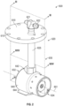
- FIG. 2 is a perspective view of the fuel injector 600 of FIG. 1 .
- the fuel injector 600 can include a flange, a fuel stem assembly 620, and an injector head 630.
- the flange 610 may be a cylindrical disk and may include mounting holes 615 for fastening the fuel injector 600 to the combustor case 398.
- the fuel stem assembly 620 can include a pilot fitting 621, a main fitting 622, and a fuel stem 625.
- the pilot fitting 621 can receive fuel from a pilot fuel source and be part of the pilot fuel circuit.
- the pilot fuel is a gas fuel. In other examples the pilot fuel is a liquid fuel.
- the pilot fitting 621 can be connected to the fuel stem 625.
- the main fitting 622 can received fuel from a main fuel source and be part of the main fuel circuit.
- the main fuel is a gas fuel.
- the main fuel is a liquid fuel.
- the pilot fuel and the main fuel are received from the same fuel source. Sometimes the pilot fuel and the main fuel are referred to as fuel.
- the main fitting 622 can be connected to the fuel stem 625.
- the injector head 630 can include an injector body 640.
- the injector head can include an injector axis 601.
- the injector axis 601 extends longitudinal to the injector head. All references to radial, axial, and circumferential directions and measures of the injector head 630 and the elements of the injector head 630 refer to the injector axis 601, and terms such as “inner” and “outer” generally indicate a lesser or greater radial distance from the injector axis 601.
- the injector head 630 can include a fuel stem receiver 642 and an injector fastener 644.
- the fuel stem receiver 642 can extend outward from the injector body 640.
- the fuel stem receiver 642 can connect with the fuel stem 625.
- the fuel stem receiver 642 and the fuel stem 625 may be metallurgically bonded, such as by brazing or welding.
- the injector fastener 644 can extend outward from the injector body 640.
- the injector fastener 644 can be located opposite from the fuel stem receiver 642.
- the injector fastener 644 can be narrower adjacent to the injector body 640 than away from the injector body 640.
- the injector head 630 can have a forward end 632 and an aft end 634 opposite the forward end 632.
- the forward end 632 can be referred to as the upstream end or upstream from the aft end 634.
- the aft end 634 can be referred to as the downstream end or downstream from the forward end 632.
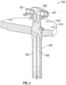
- FIG. 3 is a cross-sectional view of an embodiment of the fuel stem assembly along plane III - III of FIG. 2 .
- the fuel stem 625 can be a generally cylindrical and extend through the flange 610.
- the fuel stem 625 can include a fuel stem pilot passage 626 and a fuel stem main passage 627.
- the fuel stem pilot passage 626 can be in fluid communication with the pilot fitting 621 and be part of the pilot fuel circuit.
- the fuel stem main passage 627 can be in fluid communication with the main fitting 622 and be part of the main fuel circuit.
- the fuel stem assembly 620 can be for receiving a main fuel and a pilot fuel and distributing the main fuel and pilot fuel to the injector head 630.
- the fuel stem pilot passage 626 and the fuel stem main passage 627 can twist within the fuel stem 625.
- the fuel stem main passage 627 can be closer to the aft end 634 of the injector head than the fuel stem pilot passage 626 and at a location away from the pilot fitting 621 and the main fitting 622 the fuel stem pilot passage 626 can closer to the aft end 634 of the injector head 630 than the fuel stem main passage 627.
- the fuel stem pilot passage 626 and the fuel stem main passage 627 twist proximate to the flange 610.
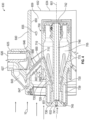
- FIG. 4 is a cross-sectional view of an embodiment of the injector head along plane IV - IV of FIG. 2 with the bottom portion not shown.
- the fuel stem receiver 642 can include a fuel stem receiver main passage 643 in fluid communication with the fuel stem main passage 627.
- the fuel stem receiver main passage 643 can be part of the main fuel circuit.
- the injector body 640 can include an injector body inner surface 650 forming a bore along the injector axis 601.
- the injector body inner surface 650 can be positioned inward of the fuel stem receiver 642.
- the injector body 640 can include a main fuel gallery 647 and a first pilot fuel gallery 646 (sometimes referred to as pilot fuel gallery).
- the main fuel gallery 647 can be positioned between the injector body inner surface 650 and the fuel stem receiver 642. In an embodiment the main fuel gallery 647 is formed by space between the injector body inner surface 650and the fuel stem receiver main passage 643.
- the main fuel gallery 647 can circumferentially extend around the injector axis 601.
- the main fuel gallery 647 can be in fluid communication with the fuel stem receiver main passage 643 and be part of the main fuel circuit.
- the first pilot fuel gallery 646 can be positioned downstream of the main fuel gallery 647. In an embodiment the first pilot fuel gallery 646 can be positioned closer to the aft end 634 of the injector head 630 than the main fuel gallery 647.
- the first pilot fuel gallery 646 can be positioned between the injector body inner surface 650 and the fuel stem receiver 642.
- the first pilot fuel gallery 646 can circumferentially extend around the injector axis 601.
- the first pilot fuel gallery 646 is formed by the space between the injector body inner surface 650 and the fuel stem pilot passage 626.
- the pilot fuel gallery 646 can be in fluid communication with the fuel stem pilot passage 626 and be part of the pilot fuel circuit.
- the injector body inner surface 650 can circumferentially extend around the injector axis 601.
- the injector body can have a premix passage forward end 651 and a premix passage aft end 652 opposite from the premix passage forward end 651.
- the premix passage aft end 652 and the aft end 634 of the injector head 630 are the same feature.
- the premix passage forward end 651 can be proximate to the main fuel gallery 647.
- the injector body 640 may include openings 655 that allow compressor discharge air 10 to enter into the injector head 630.
- the injector head 630 can include swirler vanes 660.
- the swirler vanes 660 can extend inward from the injector body 640.
- the swirler vanes 660 may have a portion that is wedge shaped and may have the tip of the wedge truncated or removed.
- the swirler vanes 660 may include other shapes configured to direct air through the injector body.
- the swirler vanes 660 can extend diagonally from the injector body inner surface 650 toward the aft end 634.
- Each of the swirler vanes 660 may include a swirler main passage 667 and swirler outlets 669.
- the swirler main passage 667 can extend inward from the injector body 640.
- the swirler main passage 667 can extend through the injector body inner surface 650 and be adjacent to the main fuel gallery 647.
- the swirler main passage 667 can be part of the main fuel circuit.
- the swirler outlets 669 can be in fluid communication with the swirler main passage 667.
- the swirler vanes 660 can include a swirler pilot passage 666 extending through the swirler vane 660.
- the swirler pilot passage 666 is positioned between the swirler main passage 667 and the aft end 634.
- the swirler pilot passage 666 can extend through the injector body inner surface 650 and be adjacent to the pilot fuel gallery 646.
- the swirler pilot passage 666 can be part of the pilot fuel circuit.
- the injector head 630 can include a pilot assembly 700.
- the pilot assembly 700 can include an outer pilot surface 710 an inner pilot surface 715, pilot struts 720, a pilot shield 730, and a pilot tube 746.
- the outer pilot surface 710 can be located inward of the injector body 640.
- the swirler vanes 660 can extend from the injector body inner 650 to the outer pilot surface 710.
- the outer pilot surface 710 can circumferentially extend around the injector axis 601.
- the swirler main passage 667 may not extend into the outer pilot surface 710.
- the swirler pilot passage 666 extends from adjacent to the first pilot fuel gallery 646 and into the pilot assembly 700.
- the swirler pilot passage can extend through the outer pilot surface 710.
- the outer pilot surface 710 can circumferentially extend around the injector axis 601.
- the outer pilot surface 710 can be positioned outward of the pilot shield 730.
- the space between the injector body inner surface 650 and the outer pilot surface 710 can form a premix passage 659.
- the inner pilot surface 715 can be positioned inward of the outer pilot surface 710.
- the inner pilot surface 715 can circumferentially extend around the injector axis 601 and form a pilot chamber 705.
- the pilot struts 720 can extend from the inner pilot surface 715 to the pilot shield 730. In an embodiment the pilot struts 720 extend diagonally towards the forward end 632 of the injector head 630. The pilot struts 720 can be radially positioned around the injector axis 601. The pilot struts 720 can be spaced apart and form feed air passages 725 between adjacent pilot struts 720, the pilot shield 730, and the inner pilot surface 715. The feed air passages 725 can direct discharge air 10 into the pilot chamber 705. Each pilot strut 720 may correspond with a specific swirler vane 660. In an embodiment, the number of pilot struts 720 can equal the number of swirler vanes 660. Each pilot strut 720 can extend from proximate to the interface between the swirler vane 660 and the pilot assembly 700.
- Each of the pilot struts (720) has a strut pilot passage (726) in fluid communication with the first pilot fuel gallery (646).
- the strut pilot passage 726 can be in fluid communication with the swirler pilot passage 666.
- the strut pilot passage 726 can extend into the pilot shield 730.
- the strut pilot passage 726 can extend through the inner pilot surface 715.
- the strut pilot passage 726 can extend inward from adjacent the swirler pilot passage 666.
- the strut pilot passage 726 can extend from proximate the outer pilot surface710 towards the forward end 632 of the injector head 630.
- the strut pilot passage 720 can extend inward from the inner pilot surface 715.
- the strut pilot passage 726 can be part of the pilot fuel circuit.
- the pilot shield 730 can circumferentially extend around the injector axis 601.
- the pilot shield 730 can be positioned inward of the inner pilot surface 715.
- the pilot shield 730 can form the forward end 632 of the injector head 630.
- the pilot shield 730 can be positioned proximate to the premix passage forward end 651.
- the pilot shield 730 can extend laterally from the pilot struts 720. A portion of the pilot shield 730 can be positioned within the pilot chamber 705.
- the pilot shield 730 can include a portion of the strut pilot passage 726, a second pilot fuel gallery 736, a pilot tube inlet 741, pilot fuel passages 745, and a portion of the pilot tube 746.
- the second pilot fuel gallery 736 can circumferentially extend around the injector axis 601.
- the second pilot fuel gallery 736 can be in fluid communication with the strut pilot passages 726.
- the second pilot fuel gallery 736 can extend from adjacent to the strut pilot passages 726 towards the forward end 632.
- the second pilot fuel gallery 736 can be part of the pilot fuel circuit.
- the pilot shield 730 can include a pilot cavity 739. can circumferentially extend around the injector axis 601. The pilot cavity 739 can help reduce the material needed to manufacture the injector head 630.
- the pilot tube 746 can circumferentially extend around the injector axis 601.
- the pilot tube 746 can extend laterally along the injector axis 601.
- the pilot tube 746 can have a pilot tube inlet 741 located proximate to the forward end 632.
- the pilot tube inlet 741 can be in fluid communication with discharge air 10. In other words, the pilot tube inlet 741 can allow air 10 to enter the pilot tube 746.
- Pilot fuel passages 745 can extend from the second pilot fuel gallery 736 to the pilot tube 746 allowing the pilot tube 746 to be in fluid communication with the second pilot fuel gallery 736.
- the pilot fuel passages 745 can be located proximate to the pilot tube inlet 741.
- the pilot tube 746 can have a pilot tube outlet 742 opposite from the pilot tube inlet 741.
- the pilot tube 746 can be part of the pilot fuel circuit.
- the present disclosure generally applies to fuel injectors 600 for gas turbine engines 100.
- the described embodiments are not limited to use in conjunction with a particular type of gas turbine engine 100, but rather may be applied to stationary or motive gas turbine engines, or any variant thereof.
- Gas turbine engines 100, and thus their components, may be suited for any number of industrial applications, such as, but not limited to, various aspects of the oil and natural gas industry (including include transmission, gathering, storage, withdrawal, and lifting of oil and natural gas), power generation industry, cogeneration, aerospace and transportation industry, to name a few examples.
- the disclosed fuel injector 600 utilizes passages 666 within the swirler vanes 660 to deliver fuel to the pilot tube 746 without additional structures impeding discharge air 10 entering the premix passage 659.
- the fuel injector 600 can include a fuel circuit.
- the fuel injector 600 can include a pilot fuel circuit and a main fuel circuit.
- the fuel injector 600 can receive fuel at the pilot fitting 621 and distribute the fuel via the pilot circuit.
- the pilot fuel circuit can continue from the pilot fitting 621 and through the fuel stem pilot passage 626.
- the fuel stem pilot passage 626 twist with the fuel stem main passage 627 to position the fuel stem pilot passage 626 to be downstream of the fuel stem main passage 627 while positioning the main fitting 622 downstream of the pilot fitting 621.
- the pilot fuel circuit can further continue from the fuel stem pilot passage 626 to the first pilot fuel gallery 646. Fuel is collected within the first pilot fuel gallery 646. The pilot fuel circuit can continue further with the swirler pilot passages 666 connecting with the first pilot fuel gallery 646 at multiple locations. The fuel is distributed from the first pilot fuel gallery 646 to the strut pilot passages 726 via the swirler pilot passage 666. The pilot fuel circuit can continue through the strut pilot passages 726 to the second pilot fuel gallery 736. The second pilot fuel gallery 736 collects the fuel from the strut pilot passages 726 and distributed around the injector axis 601 proximate to the pilot tube 746. The pilot fuel circuit can continue further with the pilot fuel passage 745 connecting with the second pilot fuel gallery 736 at multiple locations.
- the fuel is distributed from the second pilot fuel gallery 736 to the pilot tube 746 via the pilot fuel passages 745.
- the pilot fuel circuit continues with fuel entering the pilot tube 746 and mixing with discharge air 10 entering through the pilot tube inlet 741.
- the air and fuel fixture can be distributed through the pilot tube 746 and exit out of the pilot tube outlet 742 to be combusted within the combustion chamber 390.
- the fuel injector 600 can receive fuel at the main fitting 622 and distribute the fuel via the main circuit.
- the main fuel circuit can continue from the main fitting 622 and through the fuel stem main passage 627.
- the main fuel circuit can continue from the fuel stem main passage 627 to the fuel stem receiver main passage 643.
- the main fuel circuit can further continue from the fuel stem receiver main passage 643 to the main fuel gallery 647.
- Fuel is collected within the main fuel gallery 647.
- the main fuel circuit can continue further with the swirler main passages 667 connecting with the main fuel gallery 647 at multiple locations. The fuel is distributed from the main fuel gallery 647 to the swirler outlets 669 via the swirler main passage 667.
- the main fuel circuit continues with fuel exiting the swirler outlets 669 and entering the premix passage and mixing with discharge air 10 entering into the premix passage 659 proximate to the premix passage forward end 651.
- the air and fuel mixture can be distributed through the premix passage 659 and exit out of the premix passage 659 proximate to the premix passage aft end 652 to be combusted within the combustion chamber 390.
- the fuel injector 600 can be manufactured by additive manufacturing and can reduce the number of separate pieces needed to assembly the fuel injector 600. The reduced number of pieces can reduce fuel injector 600 assembly time and cost.
- the fuel stem 625 can be manufactured as one piece and be from a single parent material and the injector head 630 can be manufactured as another piece and be from a single parent material.
- the fuel stem 625 material and the injector head 630 material can be substantially similar. The similarity in materials can improve connection between the fuel stem 625 and the injector head 630 through connection methods such as brazing.
- the fuel injector 600 can be manufactured in part by forging and/or casting.
Landscapes
- Engineering & Computer Science (AREA)
- Chemical & Material Sciences (AREA)
- Combustion & Propulsion (AREA)
- Mechanical Engineering (AREA)
- General Engineering & Computer Science (AREA)
- Fuel-Injection Apparatus (AREA)
- Turbine Rotor Nozzle Sealing (AREA)
Claims (7)
- Kraftstoffinjektor (600) für ein Gasturbinentriebwerk (100), wobei der Kraftstoffinjektor (600) umfasst:eine Pilotarmatur (621);eine Hauptarmatur (622);einen Kraftstoffschaft (625), aufweisendeinen Kraftstoffschaft-Pilotdurchgang (626), der sich in der Nähe der Pilotarmatur (621) befindet und mit dieser in Fluidverbindung steht, undeinen Kraftstoffschaft-Hauptdurchgang (627) in der Nähe der Hauptarmatur (622) und in Fluidverbindung mit dieser; undeinen Injektorkopf (630), aufweisendeinen Injektorkörper (640), einschließendeine Kraftstoffschaftaufnahme (642), die den Kraftstoffschaft (625) umgibt und mit diesem verbunden ist,eine Hauptkraftstoffleitung (647) in der Nähe des Kraftstoffschaft-Hauptdurchgangs (627) und in Fluidverbindung mit diesem,eine erste Pilotkraftstoffleitung (646) in der Nähe des Kraftstoffschaft-Pilotdurchgangs (626) und in Fluidverbindung mit diesem,eine Pilotanordnung (700), die innerhalb des Injektorkörpers (640) angeordnet ist, wobei die Pilotanordnung eine äußere Pilotoberfläche (710), eine innere Pilotoberfläche (715), einen Pilotschild (730) und ein Pilotrohr (746) umfasst, undeine Mehrzahl von Verwirblerschaufeln (660), die sich vom Injektorkörper (640) nach innen zur Pilotanordnung (700) erstrecken, wobei jede der Mehrzahl von Verwirblerschaufeln (660) Folgendes einschließteinen Verwirblerpilotdurchgang (666), der sich vom Injektorkörper (640) zur Pilotanordnung (700) erstreckt, wobei der Verwirblerpilotdurchgang (666) in Fluidverbindung mit der ersten Pilotkraftstoffleitung (646) steht;dadurch gekennzeichnet, dass die Pilotanordnung (700) ferner eine Mehrzahl von Pilotstreben (720) umfasst, die voneinander beabstandet sind, wobei jede der Mehrzahl von Pilotstreben (720) einen Streben-Pilotdurchgang (726) in Fluidverbindung mit der ersten Pilotkraftstoffleitung (646) aufweist;wobei jede Pilotstrebe (720) einer bestimmten Verwirblerschaufel (660) entspricht und die Anzahl der Pilotstreben (720) gleich der Anzahl der Verwirblerschaufeln (660) ist und die Streben-Pilotdurchgänge (726) in Fluidverbindung mit dem Verwirblerpilotdurchgang (666) stehen und sich von neben dem Verwirblerpilotdurchgang (666) nach innen in den Pilotschild (730) erstrecken, undwobei der Pilotschild (730) einen Abschnitt des Streben-Pilotdurchgangs (726), eine zweite Pilotkraftstoffleitung (736), einen Pilotrohreinlass (741), Pilotkraftstoffdurchgänge (745), die an mehreren Stellen mit der zweiten Pilotkraftstoffleitung (736) verbunden sind, und einen Abschnitt des Pilotrohrs (746) einschließt;so dass Kraftstoff von der ersten Pilotkraftstoffleitung (646) durch die Verwirblerpilotdurchgänge (666) zu den Streben-Pilotdurchgängen (726), durch die Streben-Pilotdurchgänge (726) zur zweiten Pilotkraftstoffleitung (736), die den Kraftstoff von den Streben-Pilotdurchgängen (726) sammelt, verteilt wird und um die Injektorachse (601) in der Nähe des Pilotrohrs (746) herum, durch die Pilotkraftstoffdurchgänge (745) und von der zweiten Pilotkraftstoffleitung (736) über die Pilotkraftstoffdurchgänge (745) zum Pilotrohr (746) verteilt wird.
- Kraftstoffinjektor (600) nach Anspruch 1, wobei der Injektorkopf (630) ferner ein hinteres Ende (634) umfasst, wobei sich die Hauptarmatur (622) näher am hinteren Ende (634) befindet als die Pilotarmatur (621) und wobei sich die erste Pilotkraftstoffleitung (646) näher am hinteren Ende (634) befindet als die Hauptkraftstoffleitung (647).
- Kraftstoffinjektor (600) nach Anspruch 1, wobei jede der Mehrzahl von Verwirblerschaufeln (660) ferner umfasst:einen Verwirblerhauptdurchgang (667), der sich vom Injektorkörper (640) in Richtung der Pilotanordnung (700) erstreckt, wobei der Verwirblerhauptdurchgang (667) in Fluidverbindung mit der Hauptkraftstoffleitung (647) steht; undeine Mehrzahl von Verwirblerauslässen (669) in Fluidverbindung mit dem Verwirblerhauptdurchgang (667).
- Kraftstoffinjektor (600) nach Anspruch 1, wobei der Injektorkopf (630) aus einem einzigen Grundmaterial hergestellt ist.
- Kraftstoffinjektor (600) nach Anspruch 1, wobei der Injektorkopf (630) und der Kraftstoffschaft (625) aus einem im Wesentlichen ähnlichen Grundmaterial hergestellt sind.
- Kraftstoffinjektor (600) nach Anspruch 1, wobei sich der Pilotschild (730) seitlich von den Pilotstreben (720) erstreckt.
- Kraftstoffinjektor (600) nach Anspruch 6, wobei der Abschnitt eines Pilotrohrs (746), der von dem Pilotschild (730) umfasst ist, einwärts von der Mehrzahl von Pilotstreben (720) positioniert ist, wobei das Pilotrohr (746) in Fluidverbindung mit der zweiten Pilotkraftstoffleitung (736) steht.
Applications Claiming Priority (2)
| Application Number | Priority Date | Filing Date | Title |
|---|---|---|---|
| US16/600,124 US11162682B2 (en) | 2019-10-11 | 2019-10-11 | Fuel injector |
| PCT/US2020/051199 WO2021071645A1 (en) | 2019-10-11 | 2020-09-17 | Fuel injector |
Publications (2)
| Publication Number | Publication Date |
|---|---|
| EP4042071A1 EP4042071A1 (de) | 2022-08-17 |
| EP4042071B1 true EP4042071B1 (de) | 2024-11-27 |
Family
ID=72670833
Family Applications (1)
| Application Number | Title | Priority Date | Filing Date |
|---|---|---|---|
| EP20781698.4A Active EP4042071B1 (de) | 2019-10-11 | 2020-09-17 | Kraftstoffeinspritzer |
Country Status (7)
| Country | Link |
|---|---|
| US (1) | US11162682B2 (de) |
| EP (1) | EP4042071B1 (de) |
| CN (1) | CN114502884B (de) |
| AU (1) | AU2020364230B2 (de) |
| CA (1) | CA3153149A1 (de) |
| MX (1) | MX2022004111A (de) |
| WO (1) | WO2021071645A1 (de) |
Families Citing this family (3)
| Publication number | Priority date | Publication date | Assignee | Title |
|---|---|---|---|---|
| US20240093869A1 (en) * | 2022-09-15 | 2024-03-21 | Pratt & Whitney Canada Corp. | Fuel nozzle |
| US12601487B2 (en) | 2023-12-22 | 2026-04-14 | Solar Turbines Incorporated | Injector head for fuel injector |
| DE102024205468A1 (de) * | 2024-06-13 | 2025-12-18 | Rolls-Royce Deutschland Ltd & Co Kg | Injektoranordnung für ein Triebwerk und Flugzeug |
Citations (1)
| Publication number | Priority date | Publication date | Assignee | Title |
|---|---|---|---|---|
| US5778676A (en) * | 1996-01-02 | 1998-07-14 | General Electric Company | Dual fuel mixer for gas turbine combustor |
Family Cites Families (20)
| Publication number | Priority date | Publication date | Assignee | Title |
|---|---|---|---|---|
| GB1421399A (en) * | 1972-11-13 | 1976-01-14 | Snecma | Fuel injectors |
| US4735044A (en) * | 1980-11-25 | 1988-04-05 | General Electric Company | Dual fuel path stem for a gas turbine engine |
| US5404711A (en) | 1993-06-10 | 1995-04-11 | Solar Turbines Incorporated | Dual fuel injector nozzle for use with a gas turbine engine |
| US5675971A (en) * | 1996-01-02 | 1997-10-14 | General Electric Company | Dual fuel mixer for gas turbine combustor |
| US5680766A (en) * | 1996-01-02 | 1997-10-28 | General Electric Company | Dual fuel mixer for gas turbine combustor |
| US7703288B2 (en) | 2005-09-30 | 2010-04-27 | Solar Turbines Inc. | Fuel nozzle having swirler-integrated radial fuel jet |
| US7631500B2 (en) | 2006-09-29 | 2009-12-15 | General Electric Company | Methods and apparatus to facilitate decreasing combustor acoustics |
| EP3401529A1 (de) | 2013-03-14 | 2018-11-14 | United Technologies Corporation | Hohlwandiges hitzeschild für eine kraftstoffeinspritzdüsenkomponente |
| US20140367494A1 (en) | 2013-06-14 | 2014-12-18 | Delavan Inc | Additively manufactured nozzle tip for fuel injector |
| US20160003157A1 (en) | 2014-07-03 | 2016-01-07 | United Technologies Corporation | Additive manufactured tube assembly |
| US10591164B2 (en) | 2015-03-12 | 2020-03-17 | General Electric Company | Fuel nozzle for a gas turbine engine |
| US10215414B2 (en) | 2015-04-22 | 2019-02-26 | General Electric Company | System and method having fuel nozzle |
| US10364751B2 (en) | 2015-08-03 | 2019-07-30 | Delavan Inc | Fuel staging |
| GB201516977D0 (en) | 2015-09-25 | 2015-11-11 | Rolls Royce Plc | A Fuel Injector For A Gas Turbine Engine Combustion Chamber |
| US10317084B2 (en) | 2015-11-23 | 2019-06-11 | Rolls-Royce Plc | Additive layer manufacturing for fuel injectors |
| US10082082B2 (en) * | 2016-01-05 | 2018-09-25 | Solar Turbines Incorporated | Fuel injector with multi tube gas distribution |
| EP3301374A1 (de) * | 2016-09-29 | 2018-04-04 | Siemens Aktiengesellschaft | Pilotbrenneranordnung mit pilotluftversorgung |
| US10386074B2 (en) * | 2016-12-09 | 2019-08-20 | Solar Turbines Incorporated | Injector head with a resonator for a gas turbine engine |
| US10955138B2 (en) | 2017-04-25 | 2021-03-23 | Parker-Hannifin Corporation | Airblast fuel nozzle |
| US11561008B2 (en) * | 2017-08-23 | 2023-01-24 | General Electric Company | Fuel nozzle assembly for high fuel/air ratio and reduced combustion dynamics |
-
2019
- 2019-10-11 US US16/600,124 patent/US11162682B2/en active Active
-
2020
- 2020-09-17 WO PCT/US2020/051199 patent/WO2021071645A1/en not_active Ceased
- 2020-09-17 AU AU2020364230A patent/AU2020364230B2/en active Active
- 2020-09-17 CN CN202080069873.1A patent/CN114502884B/zh active Active
- 2020-09-17 EP EP20781698.4A patent/EP4042071B1/de active Active
- 2020-09-17 CA CA3153149A patent/CA3153149A1/en active Pending
- 2020-09-17 MX MX2022004111A patent/MX2022004111A/es unknown
Patent Citations (1)
| Publication number | Priority date | Publication date | Assignee | Title |
|---|---|---|---|---|
| US5778676A (en) * | 1996-01-02 | 1998-07-14 | General Electric Company | Dual fuel mixer for gas turbine combustor |
Also Published As
| Publication number | Publication date |
|---|---|
| MX2022004111A (es) | 2022-04-26 |
| EP4042071A1 (de) | 2022-08-17 |
| US20210108800A1 (en) | 2021-04-15 |
| CA3153149A1 (en) | 2021-04-15 |
| AU2020364230B2 (en) | 2025-08-21 |
| WO2021071645A1 (en) | 2021-04-15 |
| CN114502884A (zh) | 2022-05-13 |
| US11162682B2 (en) | 2021-11-02 |
| AU2020364230A1 (en) | 2022-04-28 |
| CN114502884B (zh) | 2023-07-04 |
Similar Documents
| Publication | Publication Date | Title |
|---|---|---|
| US12025314B2 (en) | Methods of operating a turbomachine combustor on hydrogen | |
| US9592480B2 (en) | Inner premix tube air wipe | |
| EP2741005A1 (de) | Brennstoffdüse für einen Verbrenner eines Gasturbinenmotors | |
| US9366190B2 (en) | Tapered gas turbine engine liquid gallery | |
| US9803863B2 (en) | Controlled-leak combustor grommet | |
| EP4042071B1 (de) | Kraftstoffeinspritzer | |
| US20160116168A1 (en) | Robust insulated fuel injector for a gas turbine engine | |
| US11662096B2 (en) | Combustor swirler to pseudo-dome attachment and interface with a CMC dome | |
| US9347378B2 (en) | Outer premix barrel vent air sweep | |
| WO2015134216A1 (en) | Gas turbine engine fuel injector with an inner heat shield | |
| EP3894750B1 (de) | Kraftstoffinjektor mit lochplatte | |
| US20160175921A1 (en) | Forged fuel injector stem | |
| US11828466B2 (en) | Combustor swirler to CMC dome attachment | |
| US9938841B2 (en) | Diaphragm assembly with a preswirler | |
| US11959445B1 (en) | Isolation of plate thermal expansion between different expansion rate materials | |
| US9890660B2 (en) | Diaphragm assembly bolted joint stress reduction | |
| US9447976B2 (en) | Fuel injector with a diffusing main gas passage |
Legal Events
| Date | Code | Title | Description |
|---|---|---|---|
| STAA | Information on the status of an ep patent application or granted ep patent |
Free format text: STATUS: UNKNOWN |
|
| STAA | Information on the status of an ep patent application or granted ep patent |
Free format text: STATUS: THE INTERNATIONAL PUBLICATION HAS BEEN MADE |
|
| PUAI | Public reference made under article 153(3) epc to a published international application that has entered the european phase |
Free format text: ORIGINAL CODE: 0009012 |
|
| STAA | Information on the status of an ep patent application or granted ep patent |
Free format text: STATUS: REQUEST FOR EXAMINATION WAS MADE |
|
| 17P | Request for examination filed |
Effective date: 20220320 |
|
| AK | Designated contracting states |
Kind code of ref document: A1 Designated state(s): AL AT BE BG CH CY CZ DE DK EE ES FI FR GB GR HR HU IE IS IT LI LT LU LV MC MK MT NL NO PL PT RO RS SE SI SK SM TR |
|
| DAV | Request for validation of the european patent (deleted) | ||
| DAX | Request for extension of the european patent (deleted) | ||
| STAA | Information on the status of an ep patent application or granted ep patent |
Free format text: STATUS: EXAMINATION IS IN PROGRESS |
|
| 17Q | First examination report despatched |
Effective date: 20230530 |
|
| GRAP | Despatch of communication of intention to grant a patent |
Free format text: ORIGINAL CODE: EPIDOSNIGR1 |
|
| STAA | Information on the status of an ep patent application or granted ep patent |
Free format text: STATUS: GRANT OF PATENT IS INTENDED |
|
| INTG | Intention to grant announced |
Effective date: 20231221 |
|
| RIN1 | Information on inventor provided before grant (corrected) |
Inventor name: LEE, HANJIE Inventor name: HUMER, STEFAN H. Inventor name: ARCHER, ROBERT Inventor name: BURKE, STEPHEN Inventor name: DUCKERS, JONATHAN G. Inventor name: EVANS, JR., TIMOTHY R. Inventor name: DOMINIQUE, DREW A. Inventor name: ROGERS, RICHARD A. |
|
| P01 | Opt-out of the competence of the unified patent court (upc) registered |
Effective date: 20240502 |
|
| GRAS | Grant fee paid |
Free format text: ORIGINAL CODE: EPIDOSNIGR3 |
|
| GRAA | (expected) grant |
Free format text: ORIGINAL CODE: 0009210 |
|
| STAA | Information on the status of an ep patent application or granted ep patent |
Free format text: STATUS: THE PATENT HAS BEEN GRANTED |
|
| AK | Designated contracting states |
Kind code of ref document: B1 Designated state(s): AL AT BE BG CH CY CZ DE DK EE ES FI FR GB GR HR HU IE IS IT LI LT LU LV MC MK MT NL NO PL PT RO RS SE SI SK SM TR |
|
| REG | Reference to a national code |
Ref country code: GB Ref legal event code: FG4D |
|
| REG | Reference to a national code |
Ref country code: CH Ref legal event code: EP |
|
| REG | Reference to a national code |
Ref country code: DE Ref legal event code: R096 Ref document number: 602020042114 Country of ref document: DE |
|
| REG | Reference to a national code |
Ref country code: IE Ref legal event code: FG4D |
|
| REG | Reference to a national code |
Ref country code: LT Ref legal event code: MG9D |
|
| REG | Reference to a national code |
Ref country code: NL Ref legal event code: MP Effective date: 20241127 |
|
| PG25 | Lapsed in a contracting state [announced via postgrant information from national office to epo] |
Ref country code: PT Free format text: LAPSE BECAUSE OF FAILURE TO SUBMIT A TRANSLATION OF THE DESCRIPTION OR TO PAY THE FEE WITHIN THE PRESCRIBED TIME-LIMIT Effective date: 20250327 Ref country code: IS Free format text: LAPSE BECAUSE OF FAILURE TO SUBMIT A TRANSLATION OF THE DESCRIPTION OR TO PAY THE FEE WITHIN THE PRESCRIBED TIME-LIMIT Effective date: 20250327 Ref country code: HR Free format text: LAPSE BECAUSE OF FAILURE TO SUBMIT A TRANSLATION OF THE DESCRIPTION OR TO PAY THE FEE WITHIN THE PRESCRIBED TIME-LIMIT Effective date: 20241127 |
|
| PG25 | Lapsed in a contracting state [announced via postgrant information from national office to epo] |
Ref country code: FI Free format text: LAPSE BECAUSE OF FAILURE TO SUBMIT A TRANSLATION OF THE DESCRIPTION OR TO PAY THE FEE WITHIN THE PRESCRIBED TIME-LIMIT Effective date: 20241127 Ref country code: NL Free format text: LAPSE BECAUSE OF FAILURE TO SUBMIT A TRANSLATION OF THE DESCRIPTION OR TO PAY THE FEE WITHIN THE PRESCRIBED TIME-LIMIT Effective date: 20241127 |
|
| REG | Reference to a national code |
Ref country code: AT Ref legal event code: MK05 Ref document number: 1746028 Country of ref document: AT Kind code of ref document: T Effective date: 20241127 |
|
| PG25 | Lapsed in a contracting state [announced via postgrant information from national office to epo] |
Ref country code: BG Free format text: LAPSE BECAUSE OF FAILURE TO SUBMIT A TRANSLATION OF THE DESCRIPTION OR TO PAY THE FEE WITHIN THE PRESCRIBED TIME-LIMIT Effective date: 20241127 |
|
| PG25 | Lapsed in a contracting state [announced via postgrant information from national office to epo] |
Ref country code: ES Free format text: LAPSE BECAUSE OF FAILURE TO SUBMIT A TRANSLATION OF THE DESCRIPTION OR TO PAY THE FEE WITHIN THE PRESCRIBED TIME-LIMIT Effective date: 20241127 |
|
| PG25 | Lapsed in a contracting state [announced via postgrant information from national office to epo] |
Ref country code: NO Free format text: LAPSE BECAUSE OF FAILURE TO SUBMIT A TRANSLATION OF THE DESCRIPTION OR TO PAY THE FEE WITHIN THE PRESCRIBED TIME-LIMIT Effective date: 20250227 |
|
| PG25 | Lapsed in a contracting state [announced via postgrant information from national office to epo] |
Ref country code: GR Free format text: LAPSE BECAUSE OF FAILURE TO SUBMIT A TRANSLATION OF THE DESCRIPTION OR TO PAY THE FEE WITHIN THE PRESCRIBED TIME-LIMIT Effective date: 20250228 Ref country code: AT Free format text: LAPSE BECAUSE OF FAILURE TO SUBMIT A TRANSLATION OF THE DESCRIPTION OR TO PAY THE FEE WITHIN THE PRESCRIBED TIME-LIMIT Effective date: 20241127 Ref country code: LV Free format text: LAPSE BECAUSE OF FAILURE TO SUBMIT A TRANSLATION OF THE DESCRIPTION OR TO PAY THE FEE WITHIN THE PRESCRIBED TIME-LIMIT Effective date: 20241127 |
|
| PG25 | Lapsed in a contracting state [announced via postgrant information from national office to epo] |
Ref country code: PL Free format text: LAPSE BECAUSE OF FAILURE TO SUBMIT A TRANSLATION OF THE DESCRIPTION OR TO PAY THE FEE WITHIN THE PRESCRIBED TIME-LIMIT Effective date: 20241127 |
|
| PG25 | Lapsed in a contracting state [announced via postgrant information from national office to epo] |
Ref country code: RS Free format text: LAPSE BECAUSE OF FAILURE TO SUBMIT A TRANSLATION OF THE DESCRIPTION OR TO PAY THE FEE WITHIN THE PRESCRIBED TIME-LIMIT Effective date: 20250227 |
|
| PG25 | Lapsed in a contracting state [announced via postgrant information from national office to epo] |
Ref country code: SM Free format text: LAPSE BECAUSE OF FAILURE TO SUBMIT A TRANSLATION OF THE DESCRIPTION OR TO PAY THE FEE WITHIN THE PRESCRIBED TIME-LIMIT Effective date: 20241127 |
|
| PG25 | Lapsed in a contracting state [announced via postgrant information from national office to epo] |
Ref country code: DK Free format text: LAPSE BECAUSE OF FAILURE TO SUBMIT A TRANSLATION OF THE DESCRIPTION OR TO PAY THE FEE WITHIN THE PRESCRIBED TIME-LIMIT Effective date: 20241127 |
|
| PG25 | Lapsed in a contracting state [announced via postgrant information from national office to epo] |
Ref country code: EE Free format text: LAPSE BECAUSE OF FAILURE TO SUBMIT A TRANSLATION OF THE DESCRIPTION OR TO PAY THE FEE WITHIN THE PRESCRIBED TIME-LIMIT Effective date: 20241127 |
|
| PG25 | Lapsed in a contracting state [announced via postgrant information from national office to epo] |
Ref country code: RO Free format text: LAPSE BECAUSE OF FAILURE TO SUBMIT A TRANSLATION OF THE DESCRIPTION OR TO PAY THE FEE WITHIN THE PRESCRIBED TIME-LIMIT Effective date: 20241127 |
|
| PG25 | Lapsed in a contracting state [announced via postgrant information from national office to epo] |
Ref country code: SK Free format text: LAPSE BECAUSE OF FAILURE TO SUBMIT A TRANSLATION OF THE DESCRIPTION OR TO PAY THE FEE WITHIN THE PRESCRIBED TIME-LIMIT Effective date: 20241127 |
|
| PG25 | Lapsed in a contracting state [announced via postgrant information from national office to epo] |
Ref country code: CZ Free format text: LAPSE BECAUSE OF FAILURE TO SUBMIT A TRANSLATION OF THE DESCRIPTION OR TO PAY THE FEE WITHIN THE PRESCRIBED TIME-LIMIT Effective date: 20241127 |
|
| PG25 | Lapsed in a contracting state [announced via postgrant information from national office to epo] |
Ref country code: IT Free format text: LAPSE BECAUSE OF FAILURE TO SUBMIT A TRANSLATION OF THE DESCRIPTION OR TO PAY THE FEE WITHIN THE PRESCRIBED TIME-LIMIT Effective date: 20241127 |
|
| REG | Reference to a national code |
Ref country code: DE Ref legal event code: R097 Ref document number: 602020042114 Country of ref document: DE |
|
| PG25 | Lapsed in a contracting state [announced via postgrant information from national office to epo] |
Ref country code: SE Free format text: LAPSE BECAUSE OF FAILURE TO SUBMIT A TRANSLATION OF THE DESCRIPTION OR TO PAY THE FEE WITHIN THE PRESCRIBED TIME-LIMIT Effective date: 20241127 |
|
| PLBE | No opposition filed within time limit |
Free format text: ORIGINAL CODE: 0009261 |
|
| STAA | Information on the status of an ep patent application or granted ep patent |
Free format text: STATUS: NO OPPOSITION FILED WITHIN TIME LIMIT |
|
| PGFP | Annual fee paid to national office [announced via postgrant information from national office to epo] |
Ref country code: DE Payment date: 20250820 Year of fee payment: 6 |
|
| PGFP | Annual fee paid to national office [announced via postgrant information from national office to epo] |
Ref country code: GB Payment date: 20250820 Year of fee payment: 6 |
|
| 26N | No opposition filed |
Effective date: 20250828 |