EP4041997B1 - System zur überwachung eines motors - Google Patents
System zur überwachung eines motors Download PDFInfo
- Publication number
- EP4041997B1 EP4041997B1 EP20790369.1A EP20790369A EP4041997B1 EP 4041997 B1 EP4041997 B1 EP 4041997B1 EP 20790369 A EP20790369 A EP 20790369A EP 4041997 B1 EP4041997 B1 EP 4041997B1
- Authority
- EP
- European Patent Office
- Prior art keywords
- oil
- engine
- polynomial function
- sensor
- electrical conductivity
- Prior art date
- Legal status (The legal status is an assumption and is not a legal conclusion. Google has not performed a legal analysis and makes no representation as to the accuracy of the status listed.)
- Active
Links
Images


Classifications
-
- F—MECHANICAL ENGINEERING; LIGHTING; HEATING; WEAPONS; BLASTING
- F01—MACHINES OR ENGINES IN GENERAL; ENGINE PLANTS IN GENERAL; STEAM ENGINES
- F01M—LUBRICATING OF MACHINES OR ENGINES IN GENERAL; LUBRICATING INTERNAL COMBUSTION ENGINES; CRANKCASE VENTILATING
- F01M11/00—Component parts, details or accessories, not provided for in, or of interest apart from, groups F01M1/00 - F01M9/00
- F01M11/10—Indicating devices; Other safety devices
-
- F—MECHANICAL ENGINEERING; LIGHTING; HEATING; WEAPONS; BLASTING
- F02—COMBUSTION ENGINES; HOT-GAS OR COMBUSTION-PRODUCT ENGINE PLANTS
- F02D—CONTROLLING COMBUSTION ENGINES
- F02D41/00—Electrical control of supply of combustible mixture or its constituents
- F02D41/22—Safety or indicating devices for abnormal conditions
-
- F—MECHANICAL ENGINEERING; LIGHTING; HEATING; WEAPONS; BLASTING
- F01—MACHINES OR ENGINES IN GENERAL; ENGINE PLANTS IN GENERAL; STEAM ENGINES
- F01M—LUBRICATING OF MACHINES OR ENGINES IN GENERAL; LUBRICATING INTERNAL COMBUSTION ENGINES; CRANKCASE VENTILATING
- F01M11/00—Component parts, details or accessories, not provided for in, or of interest apart from, groups F01M1/00 - F01M9/00
- F01M11/10—Indicating devices; Other safety devices
- F01M2011/14—Indicating devices; Other safety devices for indicating the necessity to change the oil
- F01M2011/1413—Indicating devices; Other safety devices for indicating the necessity to change the oil by considering dielectric properties
-
- F—MECHANICAL ENGINEERING; LIGHTING; HEATING; WEAPONS; BLASTING
- F01—MACHINES OR ENGINES IN GENERAL; ENGINE PLANTS IN GENERAL; STEAM ENGINES
- F01M—LUBRICATING OF MACHINES OR ENGINES IN GENERAL; LUBRICATING INTERNAL COMBUSTION ENGINES; CRANKCASE VENTILATING
- F01M11/00—Component parts, details or accessories, not provided for in, or of interest apart from, groups F01M1/00 - F01M9/00
- F01M11/10—Indicating devices; Other safety devices
- F01M2011/14—Indicating devices; Other safety devices for indicating the necessity to change the oil
- F01M2011/1446—Indicating devices; Other safety devices for indicating the necessity to change the oil by considering pressure
-
- F—MECHANICAL ENGINEERING; LIGHTING; HEATING; WEAPONS; BLASTING
- F01—MACHINES OR ENGINES IN GENERAL; ENGINE PLANTS IN GENERAL; STEAM ENGINES
- F01M—LUBRICATING OF MACHINES OR ENGINES IN GENERAL; LUBRICATING INTERNAL COMBUSTION ENGINES; CRANKCASE VENTILATING
- F01M11/00—Component parts, details or accessories, not provided for in, or of interest apart from, groups F01M1/00 - F01M9/00
- F01M11/10—Indicating devices; Other safety devices
- F01M2011/14—Indicating devices; Other safety devices for indicating the necessity to change the oil
- F01M2011/146—Indicating devices; Other safety devices for indicating the necessity to change the oil by considering moisture level
-
- F—MECHANICAL ENGINEERING; LIGHTING; HEATING; WEAPONS; BLASTING
- F01—MACHINES OR ENGINES IN GENERAL; ENGINE PLANTS IN GENERAL; STEAM ENGINES
- F01M—LUBRICATING OF MACHINES OR ENGINES IN GENERAL; LUBRICATING INTERNAL COMBUSTION ENGINES; CRANKCASE VENTILATING
- F01M11/00—Component parts, details or accessories, not provided for in, or of interest apart from, groups F01M1/00 - F01M9/00
- F01M11/10—Indicating devices; Other safety devices
- F01M2011/14—Indicating devices; Other safety devices for indicating the necessity to change the oil
- F01M2011/1473—Indicating devices; Other safety devices for indicating the necessity to change the oil by considering temperature
-
- F—MECHANICAL ENGINEERING; LIGHTING; HEATING; WEAPONS; BLASTING
- F02—COMBUSTION ENGINES; HOT-GAS OR COMBUSTION-PRODUCT ENGINE PLANTS
- F02D—CONTROLLING COMBUSTION ENGINES
- F02D2250/00—Engine control related to specific problems or objectives
- F02D2250/11—Oil dilution, i.e. prevention thereof or special controls according thereto
-
- F—MECHANICAL ENGINEERING; LIGHTING; HEATING; WEAPONS; BLASTING
- F16—ENGINEERING ELEMENTS AND UNITS; GENERAL MEASURES FOR PRODUCING AND MAINTAINING EFFECTIVE FUNCTIONING OF MACHINES OR INSTALLATIONS; THERMAL INSULATION IN GENERAL
- F16N—LUBRICATING
- F16N2200/00—Condition of lubricant
- F16N2200/04—Detecting debris, chips, swarfs
-
- Y—GENERAL TAGGING OF NEW TECHNOLOGICAL DEVELOPMENTS; GENERAL TAGGING OF CROSS-SECTIONAL TECHNOLOGIES SPANNING OVER SEVERAL SECTIONS OF THE IPC; TECHNICAL SUBJECTS COVERED BY FORMER USPC CROSS-REFERENCE ART COLLECTIONS [XRACs] AND DIGESTS
- Y02—TECHNOLOGIES OR APPLICATIONS FOR MITIGATION OR ADAPTATION AGAINST CLIMATE CHANGE
- Y02T—CLIMATE CHANGE MITIGATION TECHNOLOGIES RELATED TO TRANSPORTATION
- Y02T10/00—Road transport of goods or passengers
- Y02T10/10—Internal combustion engine [ICE] based vehicles
- Y02T10/40—Engine management systems
Definitions
- the invention relates to the field of monitoring an engine and relates more particularly to the detection of abnormal states liable to affect an engine during its operation.
- the invention aims in particular to detect certain malfunctions, damage, degradation and/or operating deviations that may affect an engine, with a view in particular to preventing them or treating them appropriately, and thus maintaining the engine in operational condition.
- Mechanical motors of the internal combustion engine or electric motor type, are ubiquitous in modern industry and more generally in everyday devices and machines. For example, a large number of vehicles (cars, trains, ships, etc.) or even industrial devices are equipped with a mechanical motor to perform a given mechanical function (rotation of the wheels of a vehicle, for example ).
- an engine uses a source of energy (heat released by the internal combustion of a fuel or a source of electrical energy) to move at least one piston in a cylinder, this translational movement being transformed into rotation by a connecting rod-crank system.
- the rotation of the motor shaft makes it possible to drive any equipment via a transmission mechanism.
- the invention makes it possible to monitor the condition of a mechanical engine from the quality of the oil circulating in the oil circuit of the engine. From the measurement of parameters representative of the quality of the oil, the system of the invention is capable of detecting any degradation and/or pollution of the quality of the oil indicating an abnormal state of the engine. This monitoring can be carried out continuously, or periodically or regularly, so as to monitor the operational state of the motor even when the latter is operating.
- the invention makes it possible to detect in an early manner (even in real time) malfunctions, anomalies, damage, operating deviations or others that an engine is likely to encounter during its life cycle.
- the invention makes it possible in particular to check whether an engine is in operational conditions or whether its performance is degraded due to any malfunction. Thanks to the invention, easy, rapid and reliability of an engine can be achieved, allowing efficient engine maintenance to be carried out when needed.
- the monitoring system comprises a control unit configured, on detection of said at least one degradation in the quality of the oil, to trigger at least one predefined action to secure the engine.
- the first parameters measured by said at least one sensor comprise at least the following parameter: relative humidity of the oil.
- at least the relative humidity of the oil is measured as a first parameter, possibly in combination with one or other first parameters, for example among those mentioned below.
- the first parameters comprise at least one parameter characterizing metallic particles likely to be present in the oil.
- the invention also relates to a corresponding monitoring method implemented by a monitoring system as defined in this document.
- the invention is implemented by means of software and/or hardware components.
- unit which can also be called “module”
- module may correspond in this document to a software component, a hardware component or a set of hardware and software components.
- the electronic device of the invention may comprise a corresponding unit configured to perform said step.
- the different steps of the method implemented by the analysis unit, by the detection unit, by the control unit, by the control unit and by the calibration unit are determined by computer program instructions.
- the invention also relates to a computer program on an information medium (or recording medium), this program being capable of being implemented in a surveillance system or more generally in a computer, this program comprising instructions adapted to the implementation of certain steps of a monitoring method as defined in this document.
- This program may use any programming language, and be in the form of source code, object code, or intermediate code between source code and object code, such as in partially compiled form, or in any other desirable form.
- the invention also relates to an information medium (or recording medium) readable by a computer, and comprising instructions of a computer program as mentioned above.
- the information carrier can be any entity or device capable of storing the program.
- the medium may include a storage medium, such as a ROM, for example a CD ROM or a microelectronic circuit ROM, or even a magnetic recording medium, for example a diskette (floppy disk) or a disk hard.
- the information medium can be a transmissible medium such as an electrical or optical signal, which can be conveyed via an electrical or optical cable, by radio or by other means.
- the program according to the invention can in particular be downloaded from an Internet-type network.
- the information carrier may be an integrated circuit in which the program is incorporated, the circuit being adapted to execute or to be used in the execution of the method in question.
- the invention relates to the monitoring of an engine operating in an oil circuit.
- the invention proposes to effectively monitor an engine by means of a monitoring system (also called management system or control system) comprising a sensor unit, an analysis unit and a detection unit.
- the sensor unit is connected to an inlet line that includes a hydraulic tubing connector configured to connect to an engine oil circuit.
- the sensor unit also includes at least one sensor configured to measure first parameters representative of the quality of an engine lubricating oil taken from the oil circuit via the inlet pipe.
- the analysis unit is configured to determine, from the first parameters, or from second parameters obtained by processing the first parameters, whether at least one predefined condition is satisfied. To do this, the analysis unit can compare these first or second parameters with at least one threshold value.
- the detection unit makes it possible to detect at least one degradation in the quality of the oil representative of an abnormal state of the engine, if said at least one predefined condition is satisfied.
- the invention also relates to a corresponding monitoring method (or management method, or even control method), to a corresponding computer program and to an information medium comprising such a program.
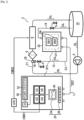
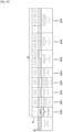
- FIG. 1 schematically represents the structure of a monitoring system SY1 and of an oil circuit C1, in accordance with a particular embodiment.
- the monitoring system SY1 and the oil circuit C1 are configured to cooperate together, thus forming a system 2.
- the oil circuit C1 comprises a mechanical motor 8 (hereinafter called “motor”), a pump 4 for injecting an engine lubricating oil OL (hereinafter called “ oil”) in the engine 8, and a sump 10 for collecting the engine lubricating oil OL evacuated at the outlet of the engine 8.
- the oil circuit C1 further comprises an oil filter 6 arranged upstream of the engine 8 to filter various types of pollution, sludge, soot or other likely to be present in the oil OL before the latter enters the engine 8.
- the filter 6 is positioned between the pump 4 and the engine 8.
- the engine 8 is an internal combustion engine, for example of the diesel engine or gas engine type, other examples of mechanical engines being however possible.
- the pump 4 is configured to circulate the oil OL at high pressure (here at a pressure between 0 and 10 bars, with a flow rate between 0 and 800 m 3 /h, for example 7 bars at 54 m 3 /h. It is however understood that the operating configuration of the main oil circuit C1, in particular in terms of pressure and flow rate, can be adapted on a case-by-case basis.
- the lubricating oil OL is an oil resistant to pollution from a combustion engine such as the engine 8 in the present case.
- the general system 2 further comprises a secondary oil circuit C2 forming a bypass connected to the main oil circuit C1 at a sampling point 18. More specifically, the secondary oil circuit C2 is a circuit of analysis comprising in this example an inlet pipe 12, a sensor unit (or measurement unit) U1 and an outlet pipe 14.
- the object of the monitoring system SY1 is to monitor the state of the engine 8 while the latter is in operation, to detect and identify abnormal states (breakdowns, damage, malfunctions, etc.) liable to affect the engine 8, and possibly securing the engine to ensure that it remains in operational condition.
- the monitoring system (also called system) SY1 comprises a sensor unit U1 (already mentioned above), an analysis unit U2, a detection unit U3, and possibly a control unit U4 and/or a U5 calibration. Other embodiments are however possible, in particular without the control unit U4 and/or without the calibration unit U5.
- the sensor unit U1 is housed in a first casing (or first device) 20 while the units U2, U3, U4 and U5 are housed in a second casing (or second device) 30 remote from the first casing 20
- the calibration unit U5 may optionally be located outside the boxes 20 and 30. These two boxes 20 and 30 are connected by a communication link L1 allowing in particular the sensor unit U1 to transmit sensor signals SG1 to the analysis unit U2, as explained below.
- Other implementations are however possible in which the units U1-U5 are for example arranged together in the same box or are arranged differently in several boxes or devices.
- the sensor unit U1 is connected to the inlet pipe 12 and to the outlet pipe 14.
- the inlet pipe 12 comprises a hydraulic pipe connector 16 (also called connection) configured to connect to the oil circuit C1 of the engine 8.
- the connector 12 has mechanical characteristics to attach to the main oil circuit C1 at the level of the sample 18 and to withstand the temperature and pressure conditions imposed by the main oil circuit C1. It can be a connector for flexible hydraulic tubing or for rigid hydraulic tubing, as the case may be.
- the connector 16 can be made of steel or of a stainless steel material to resist corrosion (in particular in marine environments).
- the connector 16 is for example a connector waterproof type 15L or other.
- an isolation valve system 3 can optionally be coupled to the connector 16 or to the inlet pipe 12 to allow, if necessary, the isolation and the purging of the system in the event of an intervention.
- the sampling point 18 at which the connector 16 is connected to the main oil circuit C1 is located between the oil filter 6 and the pump 4, other positions being however possible.
- the sensor unit U1 comprises at least one sensor SN configured to measure first parameters PR1 representative of the quality of a lubricating oil OL taken from the main oil circuit C1 via the inlet pipe 12, more precisely at the level of sampling point 18 in this example. It is assumed in this example that the sensor unit U1 comprises 2 sensors SN1, SN2 configured to measure first parameters PR1, the number and nature of the sensors possibly varying depending on the case.
- the sensors SN1 and SN2 are arranged in parallel in the secondary oil circuit C2 to measure the first parameters PR1 on the oil OL taken from the main circuit C1 at the level of the sampling point 18, while the engine 8 is in operation, or at least while the oil OL is circulating in the main oil circuit C1.
- the bypass positioning of the sensor unit U1 is advantageous in that it makes it possible to take only part of the oil flow OL circulating in the main oil circuit C1 and thus to maintain an oil flow lower in the secondary oil circuit C2 than in the main oil circuit C1.
- the oil flow can be adjusted in order to allow a more effective measurement of the quality of the oil OL.
- the oil flow rate is for example 600 m 3 /hour maximum in the main oil circuit C1 and 0.6 m 3 /hour maximum in the secondary oil circuit C2.
- the bypass configuration makes it possible to isolate the secondary oil circuit C2 if necessary and to intervene (installation, maintenance, etc.) if necessary on the monitoring system SY1 without disturbing the operation of the main oil circuit. C1.
- the SN sensors (also called “oil condition sensor” in English) make it possible to regularly, even continuously, evaluate the quality of the engine oil OL circulating in the main oil circuit C1 when the engine 8 is in operation and /or under oil pressure.
- the sensors SN can be of various types depending on the nature of the first parameters that it is desired to measure.
- the first parameters PR1 representative of the quality of the lubricating oil OL taken from the main oil circuit C1 it is possible advantageously to monitor the state of the engine 8 and detect abnormal states liable to affect the engine.
- the electrical conductivity (measured in siemens per meter, denoted S/m) here characterizes the ability of the oil OL to allow electrical charges to move freely and therefore to allow the passage of an electrical current.
- the first parameters PR1 measured by the sensors SN further comprise at least one parameter PT characterizing metallic particles likely to be present in the oil OL. They can be ferrous and/or non-ferrous particles.
- the sensors SN measure as parameter PT at least one of: the quantity of metallic particles present in the oil OL, the size of the metallic particles present in the oil OL and the weight of the metallic particles present in OL oil.
- Other updates work are however possible in which the metal particles likely to be present in the oil are not taken into account in the monitoring method of the invention.
- T, P, HR, CE, CD, and optionally PT have been selected in the present embodiment because of their inherent ability to characterize the operation of an engine so as to be able to detect and identify a wide spectrum of abnormal conditions (breakdowns, damage, malfunctions, etc.) likely to affect this engine.
- outlet pipe 14 connected to the sensor unit U1 is configured to discharge the oil OL from the sensor unit U1 into the main oil circuit C1.
- the oil OL taken from the sampling point 18 and measured by the sensors SN is evacuated in the casing 10 in order to return to the main oil circuit C1.
- the manner in which outlet conduit 14 is configured may vary depending on the case.
- the lubricating oil OL can therefore circulate in a closed circuit in the engine system 2 comprising the main circuit C1 and the secondary circuit C2.
- the monitoring system SY1 comprises the units U2, U3, U4 and U5 which are in this example housed in a box 30 separate from the box 20. It is thus possible to place the sensor unit U1 as close as possible to the main oil circuit C1 and to place the other components of the SY1 monitoring system remotely so that they are not exposed to the operating conditions of the main oil circuit C1 and to facilitate human intervention (installation, use, adjustments , maintenance, etc).
- the box 30 comprises a processor 31, a non-volatile memory 32, the units U2-U5 and a user interface 23.
- the processor 31 controlled by the computer program PG1 is here configured to implement the U2, U3, U4 and U5 units, as shown in figure 1 .
- the box 30 comprising in particular the processor 31 and the memory 32 takes for example the form of a computer or an equivalent electronic device.
- the analysis unit U2 is configured to determine, from the first parameters PR1 or from second parameters PR2 obtained by processing the first parameters PR1, whether at least one predefined condition CN is satisfied.
- the first parameters PR1 are received here in the form of signals SG1 transmitted by the sensor unit U1 via the communication link L1.
- the analysis unit U2 compares the first or second parameters PR1, PR2 with at least one predefined threshold value SL in accordance with at least one rule RL (as explained later).
- the memory 32 is a rewritable non-volatile memory (Flash, EEPRO, etc.) or a read only memory (ROM), this memory constituting a recording medium (or information medium) conforming to a particular embodiment, readable by the monitoring system SY1, and on which is recorded a computer program PG1 conforming to a particular embodiment.
- This computer program PG1 includes instructions for the execution of certain steps of a monitoring method according to a particular embodiment. The steps of this method are described later in particular embodiments.
- the memory 32 is capable of storing at least one RL rule specifying at least one EVT event associated with at least one CN condition.
- each EVT event corresponds to a particular deterioration in the quality of the oil OL detectable by the monitoring system SY1 of the invention.
- the quality of the lubricating oil OL is likely to be degraded or altered in various ways, depending on the type of malfunction encountered by the engine 8.
- the memory 32 comprises a plurality of RL rules each specifying at least one RL condition to be fulfilled for an associated EVT event to be detected.
- Each rule RL can also specify at least one AT security action triggered by the control unit U4 in response to the detection of the associated event EVT.
- An EVT event within the meaning of the invention constitutes any abnormal state of the lubricating oil OL detected by the monitoring system SY1, this state abnormal condition of the oil being itself representative (or symptomatic) of an abnormal state of the engine 8.
- an EVT event is a deterioration in the quality of the oil OL which is characterized by a particular evolution of the one or more among the parameters PR1, and optionally PR2, and which is therefore detectable by the monitoring system SY1 from these parameters.
- An EVT event can thus be (or include) one or more predefined pollutions affecting the oil OL (for example water, fuel and/or metal particle pollution), an abnormal state of its viscosity, and more generally any abnormal state of the oil detectable from the first or second parameters PR1, PR2.
- These EVT events are defined beforehand by those skilled in the art on a case-by-case basis, depending in particular on the characteristics of the engine and of the oil circuit and on the operational conditions.
- Each event EVT that is to say each type of deterioration in the quality of the oil OL, thus reflects an abnormal state of the engine 8 which requires particular attention.
- An EVT event can be representative of a damage or breakdown of the engine 8, of a deviation or degradation vis-à-vis a reference state of the engine, or of any other malfunction.
- Each abnormal state of the engine 8 is manifested by a degradation or predefined state (pollution, degradation, etc.) of the lubricating oil OL that the monitoring system SY1 is capable of detecting.
- the memory 32 can also be configured to store the first parameters PR1, and possibly also the second parameters PR2, obtained over time for a predefined period (for example for 1 year) so that a user can access them later. In association with these first and second parameters, the memory 32 can also store for this predefined duration each EVT event detected during this period as well as any AT actions triggered in response to these events. Access to this data may be useful in particular for diagnostic, monitoring, operating statistics, maintenance or other purposes.
- the control unit U4 can for example be configured to send a command CMD1 to command the motor 8 to go into a particular state (for example to trigger the stopping of the motor 8 or to modify its operating speed or any parameters of functioning).
- control unit U4 is configured to cooperate with the control unit U5 to control the state of the motor 8.
- the control unit U10 is for example configured, in response to a command CMD1 received from the control unit U4, to command motor 8 to go into a particular state by sending it an appropriate command CMD2.
- the user interface (or man-machine interface) 23 of the box 30 comprises a display screen 24 and buttons or other actuators denoted 26.
- the number, nature and configuration of these components of the user interface 23 may vary depending on the case. Other means (sound, visual, etc.) can be used as an alternative, or in addition, to interact with the user.
- the user interface 23 allows a user in particular to obtain information provided by the monitoring system SY1 and, if necessary, to act for example to secure the motor 8 in the event of an abnormal state.
- the display screen 24 here makes it possible to display NF notifications intended in particular to inform the user of detected EVT events.
- the term “notification” is understood here in the broad sense to designate any message or information which can be displayed on the screen 24 (or otherwise transmitted to the user).
- the screen can thus present NF warning messages or NF alert messages (alarms), as well as any useful information for the user such as in particular recommendations provided to the user to best deal with the detected EVT event.
- the display screen 24 is configured to display at least one gauge 36 (2 gauges in this example) to represent in real time at least one of the first or second parameters PR1, PR2, or any other parameters obtained from of these.
- buttons (or actuators) 26 in order, if necessary, to force the sending of least one command CMD1 by the control unit U4.
- a calibration may be necessary to carry out an initial configuration of the monitoring system SY1 and more particularly of the analysis unit U2.
- the calibration unit U5 is configured to carry out a calibration when such a calibration is necessary, as described later.
- the monitoring system SY1 can be the subject of an initial configuration. It is initially assumed that the monitoring system SY1 is already operational so that no initial configuration S2 is necessary.
- the measurement unit U1 measures first parameters PR1 representative of the quality of an engine lubricating oil OL taken from the main oil circuit C1 via the inlet pipe 12, at the level of the sampling point 18.
- the inlet pipe 12 takes a portion of the oil flow OL circulating in the main oil circuit C1 so as to lead it from the connector 16 to the unit of sensor U1 located in the housing 20.
- the sensors SN thus measure the first the first parameters PR1 while the sampled oil circulates in the secondary oil circuit C2.
- the sensors SN can thus measure regularly, or even continuously, the first parameters PR1 from the oil OL taken from the main oil circuit C1.
- the first parameters PR1 measured by the sensors SN can also comprise at least one parameter PT characterizing particles metals that may be present in OL oil. They can be ferrous and/or non-ferrous particles.
- the sensors SN measure as parameter PT at least one of: the quantity of metallic particles present in the oil OL, the size of metallic particles present in the oil OL and the weight of metallic particles present in OL oil.
- the characterization of the metallic particles in the oil OL makes it possible to evaluate more completely and precisely the state of the engine 8. The taking into account of these particles is however not obligatory to implement the invention.
- the sensor unit U1 thus generates signals SG1 comprising the first parameters PR1 measured (S8) by the sensors SN. These SG1 signals are transmitted via the communication link L1 to the device 30.
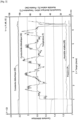
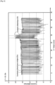
- FIG. 3 There picture 3 is a graph representing, by way of example, the evolution of the following first parameters PR1 over time: temperature T, pressure P, relative humidity HR, electrical conductivity CE and dielectric constant CD measured by the sensors SN.
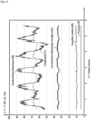
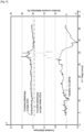
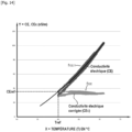
- FIG 4 is a graph representing by way of example the evolution, as first parameters PR1, of the temperature T, of the pressure P, and of two parameters PT1 and PT2 characterizing the metallic particles present in the oil OL.
- these parameters PT1 and PT2 characterize in two different ways the quantity of metallic particles (ferrous particles Fe and non-ferrous particles NFe) present in the oil OL (PT1: cumulative count of metallic particles; PT2: point count per minute metal particles).
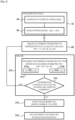
- the analysis unit U2 performs an analysis based on the first parameters PR1 received from the sensor unit U1 to determine whether at least one predefined condition CN as defined in the rules RL is satisfied. More particularly, during this analysis S10, the analysis unit U2 determines, from the first parameters PR1 or second parameters PR2 obtained by processing S12 of the first parameters PR1, whether at at least one predefined condition CN is satisfied, by comparing said first or second parameters with at least one threshold value SL.
- the analysis unit U2 determining (S14, picture 2 ) then if at least one predefined condition CN is satisfied from the first parameters PR1.
- the analysis unit U2 can thus compare each of the first parameters PR1 (or only part of them) with respective thresholds SL defined in the rules RL.
- a condition CN requires for example that a respective first parameter PR1 reaches a predefined threshold (minimum or maximum) SL.
- the analysis unit U2 carries out a processing S12 on the electrical conductivity CE and on the dielectric constant CD of the oil received from the sensor unit U1.
- This processing aims to obtain a corrected electrical conductivity CEc and a corrected dielectric constant CDc from respectively the electrical conductivity CE and the dielectric constant CD measured in S8.
- the analysis unit U2 thus performs, during the processing S12, the two operations S12a and S12b described below. These two operations S12a and S12b can be performed simultaneously or one after the other in any order. In a particular example, only one of these two operations S12a and S12b is carried out, so that only one of the corrected electrical conductivity CEc and the corrected dielectric constant CDc is determined and taken into account as the second parameter PR2 in the remainder of the method of the invention for detecting at least one EVT event.
- the analysis unit U11 determines (S12a), as second parameter PR2, a corrected electrical conductivity CEc from the electrical conductivity CE measured in S8 by applying a first polynomial function f3CE, called first final polynomial function .
- This first final polynomial function f3CE defines the corrected electrical conductivity CEc from the electrical conductivity CE, the temperature T, the pressure P and the relative humidity HR measured by the sensors SN at S8.
- the polynomial function f3CE is of order n.
- n 6 (although other orders are possible, n being an even integer) and the polynomial function f3CE is stated as follows:
- CEc To 6 ⁇ T 6 + To 5 ⁇ T 5 + To 4 ⁇ T 4 + To 3 ⁇ T 3 + To 2 ⁇ T 2 + To 1 ⁇ T + To 0 + b 6 ⁇ P 6 + b 5 ⁇ P 5 + b 4 ⁇ P 4 + b 3 ⁇ P 3 + b 2 ⁇ P 2 + b 1 ⁇ P + b 0 + vs 6 ⁇ HR 6 + vs 5 ⁇ HR 5 + vs 4 ⁇ HR 4 + vs 3 ⁇ HR 3 + vs 2 ⁇ HR 2 + vs 1 ⁇ HR + vs 0 ⁇ THIS in which CEc is the corrected electrical conductivity and CE is the measured electrical conductivity also called gross electrical conductivity.
- the first final polynomial function f3CE is weighted by first coefficients a0-a6, b0-b6 and c0-c6 (denoted collectively CFCE) associated respectively with the temperature T, the pressure P and the relative humidity HR , these coefficients being defined so as to compensate at least in part for the respective influence of the temperature T, the pressure P and the relative humidity HR on the electrical conductivity CE measured in S8 by the sensor unit U1.
- FIG. 5 represents by way of example the evolution of the corrected electrical conductivity CEc as a function of time, obtained from the processing S12a in a particular case.
- the analysis unit U11 determines (S12b), as second parameter PR2, a corrected dielectric constant CDc from the dielectric constant CD measured in S8 by applying a second polynomial function f3CD, called second polynomial function final.
- This second final polynomial function f3CD defines the corrected dielectric constant CDc from the dielectric constant CD, the temperature T, the pressure P and the relative humidity HR measured by the sensors SN at S8.
- the polynomial function f3CD is of order p.
- CDc is the corrected dielectric constant
- CD is the measured dielectric constant also called raw dielectric constant.
- the second final polynomial function f3CD is weighted by first coefficients d0-d6, e0-e6 and f0-f6 (denoted collectively CFCD) associated respectively with the temperature T, the pressure P and the relative humidity HR , these coefficients being defined so as to compensate at least in part for the respective influence of the temperature T, the pressure P and the relative humidity HR on the dielectric constant CE measured at S8 by the sensor unit U1.
- the value of the coefficients CFCE and CFCD in the polynomial functions f3CE and f3CD can be adapted as appropriate so as to compensate at an appropriate level for the influence of the variations of each of the parameters T, P and HR on respectively CE and CD.
- a way of determining these coefficients CFCE and CFCD is described later in a specific example.
- the coefficients CFCE and CFCD can in particular be chosen so that the respective correction applied to CE and CD is zero for a reference temperature Tref, a reference pressure Pref and a reference relative humidity HRref.
- the second parameters PR2 determined during the processing S12 and taken into account by the monitoring system SY1 are: the corrected electrical conductivity CEc and the corrected dielectric constant CDc obtained in S12 as well as the relative humidity HR measured in S8.
- Other examples are however possible in which other processing operations S10 are carried out and in which other parameters are used as second parameters PR2 of the invention.
- at least one parameter PT characterizing metallic particles likely to be present in the oil OL can also be taken into account as second parameter PR2 in variant embodiments.
- each RL rule stored in the memory 32 defines one or more CN rules associated with a respective event EVT and possibly with at least a corresponding AT security action.
- Each EVT event corresponds to a degradation or abnormal state of the quality of the oil OL which can occur in response to a particular malfunction of the engine 8. Examples of RL rules are described later with reference to the figure 10 .
- each condition CN defines a threshold SL (minimum or maximum) that a first parameter PR1 or second parameter PR2 must reach for the condition CN to be fulfilled.
- the analysis unit U2 thus compares the second parameters PR2 obtained in S12 (CEc, CDc and HR in this example) with associated thresholds SL (minimum or maximum), as defined in the RL rules, to determine if one or more CN conditions are satisfied.
- Each condition CN can thus define a threshold SL (maximum or minimum) which should be compared with the corrected electrical conductivity CEc, the corrected dielectric constant CDc or with the relative humidity HR.
- Step S8 If the detection unit U3 does not detect (S14) that the condition or conditions CN associated with an event EVT according to the rules RL are fulfilled, then the method resumes at step S8. Steps S8 and S10 can be repeated iteratively in order to be able to monitor the behavior of motor 8 over time.
- the detection unit U3 detects an event EVT (and therefore a deterioration in the quality of the oil OL) representative of an abnormal state of the engine 8 if at least one associated CN condition is satisfied, in accordance with the predefined RL rules.
- each EVT event corresponds to an abnormal state of the lubricating oil OL, that is to say to a deterioration in the quality of this oil compared to a reference state.
- the detection unit U3 therefore applies the rules RL to determine whether the condition(s) CN associated with an event EVT are fulfilled. If so, the U3 detection unit detects some type of oil quality degradation as as an EVT event, and therefore detects an abnormal state encountered by the engine 8.
- control unit U4 upon detection (S16) of an EVT event, can trigger (S18) at least one predefined action AT in accordance with the rules RL so as to secure the engine 8 accordingly.
- the control unit U4 can for example transmit or present an NF notification representative of the deterioration in the quality of the oil detected by the monitoring system SY1, and possibly also to indicate the state abnormal that the engine 8 potentially encounters. Users should then take the appropriate measures to verify this information and secure the engine 8 (and more generally the engine 2 system) if necessary.
- This NF notification can be transmitted to a user by any appropriate means of communication and/or presented in any appropriate form. In the example shown in figure 1 , the NF notification is displayed on the screen 24 of the user interface 23.
- the control unit U4 on detection of an EVT event, triggers the sending, by the control unit U5, of a command CMD2 to modify at least one operating parameter of the engine 8 (or another component of the main oil circuit C1) in order to secure it or at least to optimize its operation. To do this, the control unit U4 sends at least one command CMD1 to the control unit U10.
- This control unit U10 external to the device 30, therefore acts as an interface between the control unit U4 and the motor 8.
- control unit U4 commands (S18) the automatic stopping of the engine 8 in response to a deterioration in the quality of the oil OL detected in S16.
- the monitoring system SY1 carries out a processing S12 during the analysis S10 to obtain second parameters PR2, namely CEc, CDc and HR, from the first parameters (T, P , HR, CE, CD) measured on OL oil in S8.
- second parameters PR2 namely CEc, CDc and HR
- the relative humidity HR is used as the second parameter PR2 without any particular processing.
- the monitoring system SY1 can directly compare the first parameters PR1 with associated thresholds SL (minimum or maximum) as defined in the rules RL. In this case, it is not necessary to perform the processing S12 to obtain second parameters PR1 from the first parameters PR1.
- the use of the corrected electrical conductivity CEc and the corrected dielectric constant CDc is however advantageous in that it makes it possible to improve the accuracy and reliability of the monitoring system SY1 insofar as its results are less affected by possible changes climatic conditions to which the engine system 2 is exposed, thus comparing the results at iso-condition.
- Steps S8 and S10 can be carried out iteratively as long as an EVT event has not been detected (and possibly continue afterwards), in order to allow continuous monitoring of the state of the engine 8.
- the sampling point 18 where the connector 18 connects to the main oil circuit C1 is located between the pump 4 and the motor 8.
- the monitoring system SY1 is enabled to effectively control the quality of the oil OL insofar as the measurements are carried out on the oil OL before it is filtered in the oil filter 6, which makes it possible to detect the presence of any pollution, sludge, soot, degradation or others in the oil OL and therefore in the engine 8.
- the oil filter 6 is likely to mask at least partially the state of pollution of the oil OL caused by possible malfunctions of the engine 8.
- the pump can be positioned at the outlet of the motor 8. In this case, it is possible to position the sampling point 18 between the motor 8 and the casing 10 (downstream of the motor 8 and upstream of the casing 10).
- the invention therefore makes it possible to monitor the state of a mechanical motor during operation from the quality of the oil circulating in the oil circuit of the motor. From the measurement of parameters representative of the quality of the oil, the system of the invention is capable of detecting any degradation and/or pollution of the quality of the oil indicating an abnormal state of the engine. This monitoring can be carried out continuously, or periodically or regularly, so as to monitor the operational state of the motor even when the latter is operating.
- the invention makes it possible to detect in an early manner (even in real time) malfunctions, anomalies, damage, operating deviations or others that an engine is likely to encounter during its life cycle.
- the invention makes it possible in particular to check whether an engine is in operational conditions or whether its performance is degraded due to any malfunction. Thanks to the invention, an easy, rapid and reliable monitoring of an engine can be carried out, which makes it possible to carry out effective maintenance of the engine if necessary.
- the invention also makes it possible, if necessary, to warn the user of a problem encountered by the engine and to possibly trigger predefined actions to automatically secure the engine or modify its settings.
- the invention is also capable of operating without disturbing the correct operation of the engine and more generally of the oil circuit.
- the bypass configuration of the SY1 monitoring system (and more specifically of the U1 sensor unit) allows the sensors to be isolated if necessary without disturbing the main engine oil circuit.
- first parameters PR1 and possibly of the second parameters PR2, which are taken into account by the monitoring system SY1 during the analysis S10 ( picture 2 ) is left to the discretion of those skilled in the art, this choice may vary depending on the use case.
- These parameters are chosen and analyzed to enable the detection of one or more predefined states of the motor (malfunction or other).
- the sensors SN can be configured to measure, among the first parameters PR1, at least one parameter PT characterizing metallic particles (ferrous and/or non-ferrous) likely to be present in the oil OL.
- the first parameters PR1 can thus comprise as parameter PT at least one of: the quantity of metallic particles present in the oil OL, the size of metallic particles present in the oil OL and the weight of metallic particles present in OL oil.
- Each of these PT parameters can be compared during the S10 analysis ( figure 2 ) with one or more associated SL thresholds as defined in the CN conditions to determine if an EVT event is detected according to the RL rules.
- the display screen 36 ( figure 2 ) can be configured to display in real time, in the form of gauges for example, at least one parameter representative of the quality of the oil measured by the monitoring system SY1.
- the display may relate to one or more first parameters PR1 and/or second parameters PR2, or even alternatively or in addition, to at least one third parameter synthetically representing the state of the oil OL.
- the monitoring system SY1 takes into account, as second parameter PR2, the deviations of the corrected electrical conductivity CEc and of the corrected dielectric constant CDc with respect to respective reference values corresponding to a reference state of the circuit of main oil C1.
- the analysis unit U2 determines the corrected electrical conductivity CEc0, called the initial corrected electrical conductivity, of the oil OL at a reference time t0 (S40, figure 7 ). To do this, the analysis unit U2 determines the electrical conductivity CE measured at this initial instant t0 by the sensor unit U1, then calculates from the electrical conductivity CE measured at t0 the initial corrected electrical conductivity CEc0 by applying the first final polynomial function f3CE, analogously to step S12a described previously.
- the reference instant t0 can correspond to a reference period (of several hours for example) during which the electrical conductivity CE is averaged to obtain the electrical conductivity CE measured at this instant t0.
- the analysis unit U2 also determines the corrected dielectric constant CED0, called the initial corrected dielectric constant, of the oil OL at the reference instant t0 (S50, figure 7 ). To do this, the analysis unit U2 determines the dielectric constant CD measured at this initial instant t0 by the sensor unit U1, then calculates from the dielectric constant CD measured at t0 the initial corrected dielectric constant CDc0 by applying the second final polynomial function f3CD, analogously to step S12b described previously.
- the reference instant t0 can correspond to a reference period (of several hours for example) during which the dielectric constant CD is averaged for obtain the dielectric constant CD measured at this instant t0.
- Steps S40 and S50 can be performed simultaneously or in any order.
- the reference time t0 corresponds to a time when the motor 8 is in a reference state (or initial state), for example during commissioning of the motor (for example during a very first commissioning (new engine) or when returning to service following an oil change).
- the analysis unit U2 determines a second deviation DEV2 between a corrected dielectric constant CDc obtained in S12b at a current instant t (later than t0) and the initial corrected dielectric constant CDc0 obtained in S40.
- DEV 2 cdc ⁇ cdc 0 / cdc 0
- the analysis unit U2 then performs the determination step S14 ( figure 7 ) analogously to what was described previously with reference to the figure 2 .
- the analysis unit U2 uses (S14) as second parameters PR2 the deviations DEV1 and DEV2 previously obtained as well as the relative humidity HR measured in S8 to determine, on the basis of the RL rules, whether at least one CN condition is met. To do this, the analysis unit U2 therefore compares these second parameters PR2 with respective thresholds SL (minimum or maximum) defined in the conditions CN of the rules RL.
- the method continues by detecting (S16) said EVT event and by triggering (S18) at least one AT securing action, as already described above with reference to there figure 2 . Otherwise, the method continues by reiterating steps S8 and S10, as already explained.
- the figure 8 represents in a particular case the initial corrected electrical conductivity CEc0 as well as the evolution over time of the corrected electrical conductivity CEc and of the first deviation DEV1 representing the difference between CEc and CEc0.
- the figure 9 represents in a particular case the initial corrected dielectric constant CDc0 as well as the evolution over time of the corrected dielectric constant CDc and of the second deviation DEV2 representing the difference between CDc and CDc0.
- the monitoring system SY1 of the invention is capable of detecting effectively and reliably from progressive degradation over time which is likely to impact the quality of the oil OL following a malfunction or an abnormal state of the engine 8.
- the content of the RL rules, and in particular the nature and number of applicable CN conditions as well as the type of associated EVT events, can be adapted on a case-by-case basis.
- Various associations between CN conditions and detected EVT events can be predefined and represented in a diagnostic table.
- the RL rules can for example provide that at least one EVT event is detected if a single deviation only among the deviations DEV1 and DEV2 reaches a threshold SL (minimum or maximum), or alternatively, if the 2 deviations DEV1 and DEV2 each reach a respective threshold SL (minimum or maximum), possibly also taking into account the relative humidity HR with respect to a respective threshold (minimum or maximum).
- Analyzes and tests of the monitoring system SY1 implemented in the engine system 2 may be necessary to define, in each specific case, a diagnostic matrix adequately defining the conditions CN to be satisfied in order to detect an associated EVT event, from one or more thresholds SL applied to certain parameters PR1 and/or PR2.
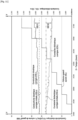
- FIG 10 thus represents the rules RL in the form of a diagnostic table, according to a particular example.
- the deviations DEV1, DEV2 and the relative humidity HR are taken into account as second parameters PR2 in the monitoring method of the invention to determine whether an EVT event according to the rules RL is detected or not in S16 .
- the RL rules define 7 distinct events EVT0-EVT7 which are each associated with 1, 2 or 3 respective CN conditions which must be fulfilled for the associated EVT event to be detected.
- a light fuel designates a fuel characterized in that its viscosity at a temperature of 40° C. is less than or equal to 100 centistokes (cSt) corresponding to 10 -4 m 2 /s, which means that a light fuel is in a liquid state at ambient temperature and pressure.
- cSt centistokes
- a fuel is said to be "heavy” if it must be maintained at a minimum temperature of 70°C to remain in the liquid state (below a temperature of 40°C, a heavy fuel becomes pasty and unusable in the engine).
- +DevCondAlmax5 is equal to 4.5 and -DevDcAlmin5 is equal to 2.
- +DevCondAlmax5 is equal to 12 and -DevDcAlmin5 is equal to -3.
- diesel pollution appears in the lubricating oil OL circulating in the main oil circuit C1.
- This pollution results from an engine malfunction, such as, for example, an anomaly in the engine gaskets, cylinder heads, liners, segmentation, injectors, injection pumps, etc.
- the addition of diesel to the oil OL is manifested in this example by an increase in the first deviation DEV1 and by a decrease in the second deviation DEV2, over time.
- the monitoring system SY1 Upon detection that DEV1 becomes greater than or equal to +DevCondAlmax5 and that DEV2 becomes less than or equal to -DevDcAlmin5, the monitoring system SY1 detects (S16) a degradation of the oil OL, namely pollution with light fuel, which is representative malfunction or abnormal condition of the engine.
- FIG 12 represents for example a particular case where water and/or fuel pollution in the oil OL is detected as event EVT1EVT2.
- the event EVT2 is detected if the following condition CN is fulfilled: the first deviation DEV1 of the corrected electrical conductivity CEc with respect to the initial corrected electrical conductivity CEc0 is greater than or equal to a maximum threshold noted -DevDCAlmin3.
- DevDCAlmin3 is equal to -5, or even to -3.
- TBN designates the total base number (for “Total Base Number” in English), expressed in mg KOH/g of oil, which characterizes the alkalinity reserve of the oil, and therefore its capacity to neutralize the acids of combustion.
- the TBN parameter is particularly representative of the state of engine oils, diesel in particular, especially in the case of use with a high sulfur fuel.
- the addition of water to the oil OL is manifested in particular by an increase over time of the first deviation DEV1.
- an increase in the second deviation DEV2 is also detectable when the amount of water added increases, it has been observed that taking this parameter into account is not necessary in this particular case to detect pollution at the water in OL oil.
- the monitoring system SY1 Upon detection that the deviation DEV2 becomes less than or equal to -DevCondAlmax1, the monitoring system SY1 detects (S16) a degradation of the oil OL, namely water pollution, which is representative of a malfunction or abnormal engine condition.
- contamination of the OL oil with water can also be detected as an EVT0 event ( figure 10 ) by determining whether the relative humidity HR is greater than or equal to a maximum threshold denoted HRAImax0.
- an S4 calibration may be necessary during an initial configuration S2 prior to steps S8-18 in order to determine the final polynomial functions f3CE and f3CD, and more particularly their respective coefficients CFCE and CFCD, making it possible to calculate the corrected electrical conductivity CEc and the dielectric constant corrected CDc.
- the coefficients a0-a6 (collectively denoted CFCE-T) define a correction CRCE-T applied to the electrical conductivity CE as a function of the temperature T.
- the coefficients b0-b6 (denoted collectively CFCE-P) define a correction CRCE-P applied to the electrical conductivity CE as a function of the pressure P.
- the coefficients c0-c6 (denoted collectively CFCE-HR) define a correction CRCE-HR applied to the electrical conductivity CE as a function of the relative humidity HR.
- the coefficients d0-d6 (collectively denoted CFCD-T) define a CRCD-T correction applied to the dielectric constant CD as a function of the temperature T.
- the coefficients e0-e6 (denoted collectively CFCD-P) define a correction CRCD-P applied to the dielectric constant CD as a function of the pressure P.
- the coefficients f0-f6 (denoted collectively CFCD-HR) define a CRCD-HR correction applied to the dielectric constant CD as a function of the relative humidity HR.
- the calibration unit U5 determines the evolution of the electrical conductivity CE measured (mathematical model of CE) by the sensors SN as a function of the temperature T measured by the SN sensors. To do this, the calibration unit U5 receives (in the form of the signals SG1) electrical conductivity values CE measured by the sensor unit U1 for different temperatures. From these values, the calibration unit U5 determines (S30) a first polynomial function f1CE representing the evolution of the electrical conductivity CE of the lubricating oil OL as a function of the temperature T.
- FIG 14 represents an example of such a polynomial prime function f1CE-T determined in S30 by the calibration unit U5.
- This function f1CE is determined by carrying out a polynomial regression from the pairs of values [CE, T] previously obtained.
- the calibration unit U5 determines a deviation denoted DEV3, as a function of the temperature T, of the electrical conductivity CE with respect to a reference electrical conductivity denoted CEref.
- This reference electrical conductivity CEref is the electrical conductivity CE defined by the function f1CE-T for a predefined reference temperature Tref.
- This temperature Tref defines a temperature at which the correction CRCE-T applied to the electrical conductivity CE to obtain a corrected electrical conductivity CEc must be zero.
- the reference temperature Tref can be chosen for example between 50°C and 85°C. In this example, the reference temperature Tref is equal to 60° C., the approximate temperature of engine 8 in normal operation.
- the calibration module U5 determines (S34, figure 13 ) then from the first polynomial function f1CE-T, and more particularly from the deviation DV3 calculated in S32 as a function of the temperature T, a second polynomial function f2CE-T representing the evolution of the deviation DV3 as a function of the temperature T.
- This second polynomial function f2CE-T defines the CRCE-T correction applied by the final polynomial function f3CE as a function of the temperature T.
- This second function f2CE-T is thus weighted by the coefficients a0-a6 defining the CRCE-T correction applied by the final polynomial function f3CE on the electrical conductivity CE as a function of temperature, so that this correction CRCE-T is zero at the reference temperature Tref.
- the calibration unit U5 thus obtains (extracts) in S36 the coefficients CFCE-T (a0-a6) to be applied in the first final polynomial function f3CE to calculate the corrected electrical conductivity CEc.
- the other CFCE coefficients (namely b0-b6 and c0-c6) of the f3CE function as well as the CFCD coefficients (d0-d6, e0-e6 and f0-f6) of the f3CD function are also determined by the calibration unit U5 by applying steps S30-S36 described above in an analogous manner.
- a first polynomial function then a second polynomial function are determined in order to deduce therefrom the coefficients defining respectively the corrections CRCE-P and CRCE-HR in the first final polynomial function f3CE and the corrections CRCD-T, CRCD-P and CRCD-HR in the second final polynomial function f3CD.
- the reference pressure Pref is between 0.5 and 10 bars, or even between 3 and 5 bars. Pref is for example equal to 4 bars. Furthermore, the reference relative humidity RH is comprised in this example between 2% and 60%, or even between 5% and 25%. HRref is for example equal to 15%.
- the polynomial coefficients CFCE and CFCD are therefore chosen here so that the respective correction applied to CE and CD by the final polynomial functions f3CE and f3CD is zero for the reference temperature Tref, the reference pressure Pref and the reference relative humidity HRref.
- the steps described above enable the calibration unit U5 to automatically determine the value of the CFCE and CFCD coefficients during the calibration step S4 ( figure 2 ).
- the analysis module U2 thus applies the coefficients CFCE and CFCD respectively in the final polynomial functions f3CE and f3CD to determine during the processing S12 the corrected electrical conductivity CEc and the corrected dielectric constant CDc as second parameters PR2.
- Other implementations of the S4 calibration are however possible.
- the implementation of the calibration step S4 is not always necessary.
- a person skilled in the art can define each of the CFCE and CFCD coefficients himself.
Landscapes
- Engineering & Computer Science (AREA)
- Mechanical Engineering (AREA)
- General Engineering & Computer Science (AREA)
- Chemical & Material Sciences (AREA)
- Combustion & Propulsion (AREA)
- Lubrication Details And Ventilation Of Internal Combustion Engines (AREA)
- Investigating Or Analyzing Materials By The Use Of Electric Means (AREA)
Claims (13)
- Überwachungssystem (SY1) zur Überwachung eines Motors (6), das umfasst:- eine Sensoreinheit (U1), die an einen Eingangskanal (12) und an einen Ausgangskanal (12) angeschlossen ist, wobei der Eingangskanal einen hydraulischen Rohrleitungsverbinder (18) umfasst, der ausgelegt ist, um sich mit einem Ölkreis (C1) des Motors zu verbinden, wobei die Sensoreinheit mindestens einen Sensor (SN) umfasst, der ausgelegt ist, um erste Parameter (PR1) zu messen, die für die Qualität eines Motorschmieröls (OL) repräsentativ sind, das dem Ölkreis über den Eingangskanal entnommen wurde, wobei der Ausgangskanal imstande ist, das Öl ab der Sensoreinheit in den Ölkreis abzuleiten;- eine Analyseeinheit (U2), die ausgelegt ist, um ausgehend von den ersten Parametern (PR1) oder von zweiten Parametern (PR2), die durch eine Verarbeitung der ersten Parameter erhalten wurden, durch Vergleichen der ersten oder zweiten Parameter mit mindestens einem Grenzwert (SL) zu bestimmen, ob mindestens eine vorbestimmte Bedingung (CN) erfüllt ist; und- eine Detektionseinheit (U3), die ausgelegt ist, um eine Verschlechterung (EVT) der Qualität des Öls zu ermitteln, die für einen anormalen Zustand des Motors repräsentativ ist, wenn die mindestens eine vorbestimmte Bedingung erfüllt ist;
wobei die Verarbeitung, die durch die Analyseeinheit (U2) durchgeführt wird, mindestens eins umfasst von:- Bestimmung, als zweiten Parameter, einer korrigierten elektrischen Leitfähigkeit ausgehend von der von dem mindestens einen Sensor gemessenen elektrischen Leitfähigkeit durch Anwenden einer ersten finalen Polynomfunktion, wobei die erste finale Polynomfunktion die korrigierte elektrische Leitfähigkeit ausgehend von der elektrischen Leitfähigkeit, der Temperatur, dem Druck und der relativen Feuchtigkeit definiert, die von dem mindestens einen Sensor gemessen wurden, wobei die erste finale Polynomfunktion von ersten Koeffizienten (CFCE) gewichtet wird, die jeweils der Temperatur, dem Druck und der relativen Feuchtigkeit zugeordnet sind, um mindestens zum Teil den jeweiligen Einfluss der Temperatur, des Drucks und der relativen Feuchtigkeit auf die von dem mindestens einen Sensor gemessene elektrische Leitfähigkeit auszugleichen; und- Bestimmung, als zweiten Parameter, einer korrigierten dielektrischen Konstante ausgehend von der von dem mindestens einen Sensor gemessenen dielektrischen Konstante durch Anwenden einer zweiten finalen Polynomfunktion, wobei die zweite finale Polynomfunktion die korrigierte dielektrische Konstante ausgehend von der dielektrischen Konstante, der Temperatur, dem Druck und der relativen Feuchtigkeit definiert, die von dem mindestens einen Sensor gemessen wurden, wobei die zweite finale Polynomfunktion von zweiten Koeffizienten (CFCD) gewichtet wird, die jeweils der Temperatur, dem Druck und der relativen Feuchtigkeit zugeordnet sind, um mindestens zum Teil den jeweiligen Einfluss der Temperatur, des Drucks und der relativen Feuchtigkeit auf die von dem mindestens einen Sensor gemessene dielektrische Konstante auszugleichen;
wobei das Analysemodul ausgelegt ist, um mindestens eins von der korrigierten elektrischen Leitfähigkeit und der korrigierten dielektrischen Konstante mit einem jeweiligen Grenzwert zu vergleichen, um zu bestimmen, ob die mindestens eine vorbestimmte Bedingung erfüllt ist. - System nach Anspruch 1, umfassend:- eine Kontrolleinheit (U4), die ausgelegt ist, um nach Ermittlung mindestens einer Verschlechterung der Qualität des Öls mindestens eine vorbestimmte Aktion (AT) zur Sicherung des Motors auszulösen.
- System nach Anspruch 2, wobei die mindestens eine Aktion mindestens eins umfasst von:- Übertragung oder Präsentation einer Mitteilung (NF), die für die Verschlechterung der Qualität des Öls repräsentativ ist; und- Auslösen eines Versands durch eine Steuereinheit (U10) eines Befehls (CMD2) zum Ändern mindestens eines Betriebsparameters des Motors.
- System nach einem der Ansprüche 1 bis 3, wobei die ersten Parameter, die von dem mindestens einen Sensor gemessen wurden, die folgenden Parameter umfassen:- elektrische Leitfähigkeit des Öls;- dielektrische Konstante des Öls;- Temperatur des Öls;- Druck des Öls; und- relative Feuchtigkeit des Öls.
- System nach einem der Ansprüche 1 bis 4, wobei die ersten Parameter mindestens einen Parameter umfassen, der Metallpartikel charakterisiert, die in dem Öl vorhanden sein könnten.
- System nach einem der Ansprüche 1 bis 5, wobei das Analysemodul ausgelegt ist, um die korrigierte elektrische Leitfähigkeit und die korrigierte dielektrische Konstante bei der Verarbeitung zu bestimmen,
wobei die mindestens eine vorbestimmte Bedingung die folgenden Bedingungen umfasst:- die korrigierte elektrische Leitfähigkeit erreicht einen ersten Grenzwert; und- die korrigierte dielektrische Konstante erreicht einen zweiten Grenzwert. - System nach einem der Ansprüche 1 bis 6, das eine Kalibriereinheit (U5) umfasst, die ausgelegt ist, um vor der Analyse die ersten und zweiten Koeffizienten zu bestimmen, die jeweils die erste und zweite finale Polynomfunktion gewichten, wobei die Kalibriereinheit ausgelegt ist, um die folgenden Schritte durchzuführen:- Bestimmung einer ersten Polynomfunktion f1CE-T, die die Entwicklung der elektrischen Leitfähigkeit repräsentiert, die von dem mindestens einen Sensor in Abhängigkeit von der Temperatur gemessen wurde, die von dem mindestens einen Sensor gemessen wurde;- Bestimmung einer ersten Polynomfunktion f1CE-P, die die Entwicklung der elektrischen Leitfähigkeit repräsentiert, die von dem mindestens einen Sensor in Abhängigkeit von dem Druck gemessen wurde, der von dem mindestens einen Sensor gemessen wurde;- Bestimmung einer ersten Polynomfunktion f1CE-HR, die die Entwicklung der elektrischen Leitfähigkeit repräsentiert, die von dem mindestens einen Sensor in Abhängigkeit von der relativen Feuchtigkeit gemessen wurde, die von dem mindestens einen Sensor gemessen wurde;- Bestimmung einer ersten Polynomfunktion f1CD-T, die die Entwicklung der dielektrischen Konstante repräsentiert, die von dem mindestens einen Sensor in Abhängigkeit von der Temperatur gemessen wurde, die von dem mindestens einen Sensor gemessen wurde;- Bestimmung einer ersten Polynomfunktion f1CD-P, die die Entwicklung der dielektrischen Konstante repräsentiert, die von dem mindestens einen Sensor in Abhängigkeit von dem Druck gemessen wurde, der von dem mindestens einen Sensor gemessen wurde;- Bestimmung einer ersten Polynomfunktion f1CD-HR, die die Entwicklung der dielektrischen Konstante repräsentiert, die von dem mindestens einen Sensor in Abhängigkeit von der relativen Feuchtigkeit gemessen wurde, die von dem mindestens einen Sensor gemessen wurde;- Bestimmung, ausgehend von der ersten Polynomfunktion f1CE-T, einer zweiten Polynomfunktion f2CE-T, die eine Korrektur CRCE-T der elektrischen Leitfähigkeit in Abhängigkeit von der Temperatur definiert, wobei die zweite Polynomfunktion f2CE-T von den ersten Koeffizienten gewichtet wird, die die Korrektur CRCE-T derart definieren, dass sie bei einer Referenztemperatur null ist;- Bestimmung, ausgehend von der ersten Polynomfunktion f1CE-P, einer zweiten Polynomfunktion f2CE-P, die eine Korrektur CRCE-P der elektrischen Leitfähigkeit in Abhängigkeit vom Druck definiert, wobei die zweite Polynomfunktion f2CE-P von den ersten Koeffizienten gewichtet wird, die die Korrektur derart definieren, dass sie bei einem Referenzdruck null ist;- Bestimmung, ausgehend von der ersten Polynomfunktion f1CE-HR, einer zweiten Polynomfunktion f2CE-HR, die eine Korrektur CRCE-HR der elektrischen Leitfähigkeit in Abhängigkeit von der relativen Feuchtigkeit definiert, wobei die zweite Polynomfunktion f2CE-HR von den ersten Koeffizienten gewichtet wird, die die Korrektur derart definieren, dass sie bei einer relativen Referenzfeuchtigkeit null ist;- Bestimmung, ausgehend von der ersten Polynomfunktion f1CD-T, einer zweiten Polynomfunktion f2CD-T, die eine Korrektur CRCD-T der dielektrischen Konstante in Abhängigkeit von der Temperatur definiert, wobei die zweite Polynomfunktion f2CD-T von den zweiten Koeffizienten gewichtet wird, die die Korrektur derart definieren, dass sie bei der Referenztemperatur null ist;- Bestimmung, ausgehend von der ersten Polynomfunktion f1CD-P, einer zweiten Polynomfunktion f2CD-P, die eine Korrektur CRCD-P der dielektrischen Konstante in Abhängigkeit vom Druck definiert, wobei die zweite Polynomfunktion f2CD-P von den zweiten Koeffizienten gewichtet wird, die die Korrektur derart definieren, dass sie beim Referenzdruck null ist; und- Bestimmung, ausgehend von der ersten Polynomfunktion f1CD-HR, einer zweiten Polynomfunktion f2CD-HR, die eine Korrektur CRCD-HR der dielektrischen Konstante in Abhängigkeit von der relativen Feuchtigkeit definiert, wobei die zweite Polynomfunktion f2CD-HR von den zweiten Koeffizienten gewichtet wird, die die Korrektur derart definieren, dass sie bei der relativen Referenzfeuchtigkeit null ist;
wobei das Analysemodul ausgelegt ist, um die ersten und zweiten Koeffizienten in jeweils der ersten und zweiten finalen Polynomfunktion anzuwenden, um bei der Verarbeitung die korrigierte elektrische Leitfähigkeit und die korrigierte dielektrische Konstante als zweite Parameter zu bestimmen. - System nach einem der Ansprüche 1 bis 7, wobei das Analysemodul ausgelegt ist, um bei einer Lernphase durchzuführen:- Bestimmung einer korrigierten elektrischen Ausgangs-Leitfähigkeit und einer korrigierten dielektrischen Ausgangs-Konstante ausgehend jeweils von der elektrischen Leitfähigkeit und von der dielektrischen Konstante, die von dem mindestens einen Sensor in einem Referenzzustand des Ölkreises gemessen wurden;
wobei das Analysemodul ferner ausgelegt ist, um bei der Verarbeitung durchzuführen:- Berechnung einer ersten Abweichung zwischen einer korrigierten elektrischen Leitfähigkeit, die zu einem laufenden Zeitpunkt im Verhältnis zu der korrigierten elektrischen Ausgangs-Leitfähigkeit bestimmt wurde, und einer zweiten Abweichung zwischen einer korrigierten dielektrischen Konstante, die zu einem laufenden Zeitpunkt im Verhältnis zu korrigierten dielektrischen Ausgangs-Konstante bestimmt wurde; und- Bestimmung, dass die mindestens eine vorbestimmte Bedingung erfüllt ist, wenn mindestens eine von der ersten und zweiten Abweichung einen vorbestimmten Grenzwert erreicht. - System nach Anspruch 8, wobei:- wenn die erste Abweichung einen ersten vorbestimmten minimalen Grenzwert erreicht, ist das Detektionsmodul ausgelegt, um als Verschlechterung der Qualität des Öls ein anormales Viskositätsniveau des Öls zu ermitteln;- wenn die erste Abweichung einen zweiten vorbestimmten maximalen Grenzwert erreicht, ist das Detektionsmodul ausgelegt, um als Verschlechterung der Qualität des Öls eine Kraftstoffverschmutzung des Öls zu ermitteln;- wenn die zweite Abweichung einen dritten vorbestimmten minimalen Grenzwert erreicht, ist das Detektionsmodul ausgelegt, um als Verschlechterung der Qualität des Öls eine Rußverschmutzung des Öls zu ermitteln; und- wenn die zweite Abweichung einen vierten vorbestimmten maximalen Grenzwert erreicht, ist das Detektionsmodul ausgelegt, um als Verschlechterung der Qualität des Öls einen anormalen Basizitätsgehalt des Öls zu ermitteln.
- System nach Anspruch 8 oder 9, wobei:- wenn die erste Abweichung einen fünften vorbestimmten maximalen Grenzwert erreicht und wenn die zweite Abweichung einen sechsten vorbestimmten minimalen Grenzwert erreicht, ist das Detektionsmodul ausgelegt, um als Verschlechterung der Qualität des Öls eine Leichtölverschmutzung des Öls zu ermitteln;- wenn die erste Abweichung einen siebten vorbestimmten maximalen Grenzwert erreicht und wenn die zweite Abweichung einen achten vorbestimmten maximalen Grenzwert erreicht, ist das Detektionsmodul ausgelegt, um als Verschlechterung der Qualität des Öls eine Schwerölverschmutzung des Öls zu ermitteln; und- wenn die relative Feuchtigkeit einen neunten vorbestimmten maximalen Grenzwert erreicht, wenn die erste Abweichung einen zehnten vorbestimmten maximalen Grenzwert erreicht und wenn die zweite Abweichung einen elften vorbestimmten maximalen Grenzwert erreicht, ist das Detektionsmodul ausgelegt, um als Verschlechterung der Qualität des Öls einen anormalen Eisengehalt des Öls zu ermitteln.
- Motorsystem (2), umfassend:- einen Ölkreis, der einen Motor, eine Pumpe zum Einleiten eines Motorschmieröls in den Motor und ein Gehäuse zum Sammeln des am Ausgang des Motors ausgeleiteten Motorschmieröls aufweist; und- ein Überwachungssystem nach einem der Ansprüche 1 bis 10, wobei der Verbinder des Eingangskanals mit dem Ölkreis derart verbunden ist, dass Motorschmieröl entnommen wird, das in dem Ölkreis zirkuliert, und wobei der Ausgangskanal ausgelegt ist, um das Schmieröl in das Gehäuse abzuleiten.
- Motorsystem nach Anspruch 11, wobei der Ölkreis ferner einen Ölfilter umfasst, der zwischen der Pumpe und dem Motor angeordnet ist,
wobei der Verbinder des Eingangskanals mit dem Ölkreis im Bereich eines Entnahmepunkts verbunden ist, der sich befindet:- zwischen der Pumpe und dem Ölfilter derart, dass er der Pumpe nachgelagert und dem Motor vorgelagert ist; oder- zwischen der Pumpe und dem Motor derart, dass er dem Motor nachgelagert und der Pumpe vorgelagert ist. - Verfahren zur Überwachung eines Motors (8), das von einem Überwachungssystem (SY1) durchgeführt wird, das mindestens einen Sensor (SN) umfasst und über einen Eingangskanal (12) an einen Ölkreis (C1) des Motors angeschlossen ist, wobei das Verfahren umfasst:- Messung (S8), durch den mindestens einen Sensor, von ersten Parametern (PR1), die für die Qualität eines Motorschmieröls (OL) repräsentativ sind, das dem Ölkreis über den Eingangskanal entnommen wird, wobei das Öl nach der Messung in den Ölkreis über einen Ausgangskanal (14) des Überwachungssystems abgeleitet wird;- Analyse (S10), ausgehend von den ersten Parametern (PR1) oder von zweiten Parametern (PR2), die von einer Verarbeitung der ersten Parameter erhalten wurden, um durch Vergleichen der ersten oder zweiten Parameter mit mindestens einem Grenzwert zu bestimmen, ob mindestens eine vorbestimmte Bedingung erfüllt ist; und- Ermittlung (S16) mindestens einer vorbestimmten Verschlechterung der Qualität des Öls, die für einen anormalen Zustand des Motors repräsentativ ist, wenn die mindestens eine vorbestimmte Bedingung erfüllt ist;
wobei die Verarbeitung mindestens eins umfasst von:- Bestimmung, als zweiten Parameter, einer korrigierten elektrischen Leitfähigkeit ausgehend von der von dem mindestens einen Sensor gemessenen elektrischen Leitfähigkeit durch Anwenden einer ersten finalen Polynomfunktion, wobei die erste finale Polynomfunktion die korrigierte elektrische Leitfähigkeit ausgehend von der elektrischen Leitfähigkeit, der Temperatur, dem Druck und der relativen Feuchtigkeit definiert, die von dem mindestens einen Sensor gemessen wurden, wobei die erste finale Polynomfunktion von ersten Koeffizienten (CFCE) gewichtet wird, die jeweils der Temperatur, dem Druck und der relativen Feuchtigkeit zugeordnet sind, um mindestens zum Teil den jeweiligen Einfluss der Temperatur, des Drucks und der relativen Feuchtigkeit auf die von dem mindestens einen Sensor gemessene elektrische Leitfähigkeit auszugleichen; und- Bestimmung, als zweiten Parameter, einer korrigierten dielektrischen Konstante ausgehend von der von dem mindestens einen Sensor gemessenen dielektrischen Konstante durch Anwenden einer zweiten finalen Polynomfunktion, wobei die zweite finale Polynomfunktion die korrigierte dielektrische Konstante ausgehend von der dielektrischen Konstante, der Temperatur, dem Druck und der relativen Feuchtigkeit definiert, die von dem mindestens einen Sensor gemessen wurden, wobei die zweite finale Polynomfunktion von zweiten Koeffizienten (CFCD) gewichtet wird, die jeweils der Temperatur, dem Druck und der relativen Feuchtigkeit zugeordnet sind, um mindestens zum Teil den jeweiligen Einfluss der Temperatur, des Drucks und der relativen Feuchtigkeit auf die von dem mindestens einen Sensor gemessene dielektrische Konstante auszugleichen;
wobei die Analyse einen Vergleich von mindestens einer von der korrigierten elektrischen Leitfähigkeit und der korrigierten dielektrischen Konstante mit einem jeweiligen Grenzwert umfasst, um zu bestimmen, ob die mindestens eine vorbestimmte Bedingung erfüllt ist.
Applications Claiming Priority (2)
| Application Number | Priority Date | Filing Date | Title |
|---|---|---|---|
| FR1911183A FR3101916B1 (fr) | 2019-10-09 | 2019-10-09 | Système de surveillance d’un moteur |
| PCT/FR2020/051660 WO2021069811A1 (fr) | 2019-10-09 | 2020-09-24 | Système de surveillance d'un moteur |
Publications (3)
| Publication Number | Publication Date |
|---|---|
| EP4041997A1 EP4041997A1 (de) | 2022-08-17 |
| EP4041997B1 true EP4041997B1 (de) | 2023-06-07 |
| EP4041997C0 EP4041997C0 (de) | 2023-06-07 |
Family
ID=68988015
Family Applications (1)
| Application Number | Title | Priority Date | Filing Date |
|---|---|---|---|
| EP20790369.1A Active EP4041997B1 (de) | 2019-10-09 | 2020-09-24 | System zur überwachung eines motors |
Country Status (4)
| Country | Link |
|---|---|
| US (1) | US11746680B2 (de) |
| EP (1) | EP4041997B1 (de) |
| FR (1) | FR3101916B1 (de) |
| WO (1) | WO2021069811A1 (de) |
Families Citing this family (3)
| Publication number | Priority date | Publication date | Assignee | Title |
|---|---|---|---|---|
| FR3101916B1 (fr) | 2019-10-09 | 2022-05-06 | Man Energy Solutions France | Système de surveillance d’un moteur |
| CN114323660B (zh) * | 2022-01-10 | 2023-09-26 | 中车大连机车车辆有限公司 | 一种低误报率碾瓦位置可视的高效柴油机碾瓦报警装置 |
| CN120820703A (zh) * | 2024-04-12 | 2025-10-21 | 安徽容知日新科技股份有限公司 | 一种油液在线监测设备及其操作方法 |
Family Cites Families (11)
| Publication number | Priority date | Publication date | Assignee | Title |
|---|---|---|---|---|
| US5964318A (en) * | 1998-01-12 | 1999-10-12 | The Lubrizol Corporation | System for maintaining the quality and level of lubricant in an engine |
| US7043969B2 (en) * | 2002-10-18 | 2006-05-16 | Symyx Technologies, Inc. | Machine fluid sensor and method |
| US20190156600A1 (en) * | 2006-11-16 | 2019-05-23 | Ge Global Sourcing Llc | Locomotive sensor system for monitoring engine and lubricant health |
| US20080302606A1 (en) * | 2007-06-08 | 2008-12-11 | Glacier Bay, Inc. | Oil replacement system |
| US20090139484A1 (en) * | 2007-11-30 | 2009-06-04 | Caterpillar Inc. | Automatically adjustable oil renewal system |
| JP5558337B2 (ja) * | 2010-12-27 | 2014-07-23 | 三菱重工業株式会社 | エンジンにおける潤滑油の補充装置 |
| DE102013005003A1 (de) * | 2013-03-22 | 2014-09-25 | Ulrich Kuipers | Verfahren zur Messung kritischer Betriebszustände von Maschinenelementen und zur Verschleißbegrenzungsregelung von Anlagen |
| US20150082871A1 (en) * | 2013-09-20 | 2015-03-26 | Cummins Inc. | Onboard diagnostic of engine oil quality by using a transfer function with a plurality of fluid property sensors |
| WO2016140731A1 (en) * | 2015-03-05 | 2016-09-09 | Sikorsky Aircraft Corporation | Fluid condition monitoring device |
| CN110382827B (zh) * | 2017-03-08 | 2021-09-10 | 康明斯滤清系统知识产权公司 | 使过滤器元件和润滑剂流体的维护警报同步的系统和方法 |
| FR3101916B1 (fr) | 2019-10-09 | 2022-05-06 | Man Energy Solutions France | Système de surveillance d’un moteur |
-
2019
- 2019-10-09 FR FR1911183A patent/FR3101916B1/fr active Active
-
2020
- 2020-09-24 WO PCT/FR2020/051660 patent/WO2021069811A1/fr not_active Ceased
- 2020-09-24 US US17/767,673 patent/US11746680B2/en active Active
- 2020-09-24 EP EP20790369.1A patent/EP4041997B1/de active Active
Also Published As
| Publication number | Publication date |
|---|---|
| WO2021069811A1 (fr) | 2021-04-15 |
| US11746680B2 (en) | 2023-09-05 |
| US20230145029A1 (en) | 2023-05-11 |
| EP4041997C0 (de) | 2023-06-07 |
| FR3101916B1 (fr) | 2022-05-06 |
| FR3101916A1 (fr) | 2021-04-16 |
| EP4041997A1 (de) | 2022-08-17 |
Similar Documents
| Publication | Publication Date | Title |
|---|---|---|
| EP4041997B1 (de) | System zur überwachung eines motors | |
| EP2376988B1 (de) | Standardisierung von daten verwendeten zur überwachung eines flugzeugtriebwerks | |
| FR2949352A1 (fr) | Surveillance d'un filtre servant au filtrage d'un fluide dans un moteur d'aeronef | |
| FR2963960A1 (fr) | Surveillance des particules dans un systeme de lubrification | |
| EP3039497B1 (de) | Überwachung eines flugzeugmotors zur vorausplanung von wartungsoperationen | |
| EP2630548B1 (de) | Verfahren und vorrichtung zur überwachung einer rückkopplungsschleife mit betätigungssystem mit variabler geometrie eines triebwerks | |
| FR3065995B1 (fr) | Systeme et procede de surveillance d'une turbomachine a detection d'anomalie corrigee par un facteur d'usure | |
| FR3093768A1 (fr) | Procédé et système de surveillance d’un état d’un réducteur d’une turbine à gaz | |
| EP3839679B1 (de) | Verfahren zur kontrolle eines qualitätsniveaus der verschraubung eines schraubers, entsprechende vorrichtung und programm zur umsetzung dieses verfahrens | |
| EP3842185B1 (de) | Verfahren zur unterstützung der wartung eines industriewerkzeugs, entsprechendes werkzeug und system, sowie programm zur durchführung des verfahrens | |
| FR3035232A1 (fr) | Systeme de surveillance de l'etat de sante d'un moteur et procede de configuration associe | |
| FR3014502A1 (fr) | Procede et dispositif de detection de defauts mecaniques dans une machine tournante a regime variable | |
| EP2240676B1 (de) | Verfahren zur erkennung von stromimpulsen und zur verwaltung des betriebs eines motors | |
| CA3127551A1 (fr) | Procede de surveillance de l'etat de fonctionnement d'un systeme de positionnement d'organes a geometrie variable d'une turbomachine | |
| FR3140185A1 (fr) | Procédé et dispositif de détection d’anomalie de fonctionnement d’un aéronef | |
| FR3030624A1 (fr) | Procede et dispositif d'obtention d'une pression differentielle de reference d'un fluide traversant un filtre d'un moteur d'aeronef | |
| EP3789687B1 (de) | Zustandsbestimmungsverfahren für heizsystem | |
| EP3729003B1 (de) | Detektion und unterbringung von intermittierenden offenen schaltungen an einem motorsensor eines flugzeugturbinentriebwerks | |
| FR3156733A1 (fr) | Procede de controle de valve de systeme de frein de parking | |
| WO2025219666A1 (fr) | Procede d'evaluation d'une duree de vie residuelle d'une piece d'un systeme hydraulique, et dispositif electronique associe | |
| FR3144279A1 (fr) | Procédé et dispositif de surveillance d’une machine tournante à partir d’un signal vibratoire | |
| EP4564035A1 (de) | Verfahren und vorrichtung zur erkennung eines fehlers einer bleibatterie | |
| FR3120145A1 (fr) | Procédé d’évaluation de l’usure d’une pièce d’une turbomachine | |
| FR3094485A1 (fr) | Procédé de prévision d’une panne d’un composant électromécanique | |
| FR3076633A1 (fr) | Procede de gestion de defauts averes pour un calculateur moteur |
Legal Events
| Date | Code | Title | Description |
|---|---|---|---|
| STAA | Information on the status of an ep patent application or granted ep patent |
Free format text: STATUS: UNKNOWN |
|
| STAA | Information on the status of an ep patent application or granted ep patent |
Free format text: STATUS: THE INTERNATIONAL PUBLICATION HAS BEEN MADE |
|
| PUAI | Public reference made under article 153(3) epc to a published international application that has entered the european phase |
Free format text: ORIGINAL CODE: 0009012 |
|
| STAA | Information on the status of an ep patent application or granted ep patent |
Free format text: STATUS: REQUEST FOR EXAMINATION WAS MADE |
|
| 17P | Request for examination filed |
Effective date: 20220412 |
|
| AK | Designated contracting states |
Kind code of ref document: A1 Designated state(s): AL AT BE BG CH CY CZ DE DK EE ES FI FR GB GR HR HU IE IS IT LI LT LU LV MC MK MT NL NO PL PT RO RS SE SI SK SM TR |
|
| GRAP | Despatch of communication of intention to grant a patent |
Free format text: ORIGINAL CODE: EPIDOSNIGR1 |
|
| STAA | Information on the status of an ep patent application or granted ep patent |
Free format text: STATUS: GRANT OF PATENT IS INTENDED |
|
| INTG | Intention to grant announced |
Effective date: 20221125 |
|
| DAV | Request for validation of the european patent (deleted) | ||
| DAX | Request for extension of the european patent (deleted) | ||
| GRAS | Grant fee paid |
Free format text: ORIGINAL CODE: EPIDOSNIGR3 |
|
| GRAA | (expected) grant |
Free format text: ORIGINAL CODE: 0009210 |
|
| STAA | Information on the status of an ep patent application or granted ep patent |
Free format text: STATUS: THE PATENT HAS BEEN GRANTED |
|
| AK | Designated contracting states |
Kind code of ref document: B1 Designated state(s): AL AT BE BG CH CY CZ DE DK EE ES FI FR GB GR HR HU IE IS IT LI LT LU LV MC MK MT NL NO PL PT RO RS SE SI SK SM TR |
|
| REG | Reference to a national code |
Ref country code: GB Ref legal event code: FG4D Free format text: NOT ENGLISH |
|
| REG | Reference to a national code |
Ref country code: CH Ref legal event code: EP Ref country code: AT Ref legal event code: REF Ref document number: 1575723 Country of ref document: AT Kind code of ref document: T Effective date: 20230615 |
|
| REG | Reference to a national code |
Ref country code: DE Ref legal event code: R096 Ref document number: 602020012295 Country of ref document: DE |
|
| U01 | Request for unitary effect filed |
Effective date: 20230607 |
|
| U07 | Unitary effect registered |
Designated state(s): AT BE BG DE DK EE FI FR IT LT LU LV MT NL PT SE SI Effective date: 20230612 |
|
| REG | Reference to a national code |
Ref country code: LT Ref legal event code: MG9D |
|
| PG25 | Lapsed in a contracting state [announced via postgrant information from national office to epo] |
Ref country code: NO Free format text: LAPSE BECAUSE OF FAILURE TO SUBMIT A TRANSLATION OF THE DESCRIPTION OR TO PAY THE FEE WITHIN THE PRESCRIBED TIME-LIMIT Effective date: 20230907 Ref country code: ES Free format text: LAPSE BECAUSE OF FAILURE TO SUBMIT A TRANSLATION OF THE DESCRIPTION OR TO PAY THE FEE WITHIN THE PRESCRIBED TIME-LIMIT Effective date: 20230607 |
|
| PG25 | Lapsed in a contracting state [announced via postgrant information from national office to epo] |
Ref country code: RS Free format text: LAPSE BECAUSE OF FAILURE TO SUBMIT A TRANSLATION OF THE DESCRIPTION OR TO PAY THE FEE WITHIN THE PRESCRIBED TIME-LIMIT Effective date: 20230607 Ref country code: HR Free format text: LAPSE BECAUSE OF FAILURE TO SUBMIT A TRANSLATION OF THE DESCRIPTION OR TO PAY THE FEE WITHIN THE PRESCRIBED TIME-LIMIT Effective date: 20230607 Ref country code: GR Free format text: LAPSE BECAUSE OF FAILURE TO SUBMIT A TRANSLATION OF THE DESCRIPTION OR TO PAY THE FEE WITHIN THE PRESCRIBED TIME-LIMIT Effective date: 20230908 |
|
| U21 | Renewal fee for the european patent with unitary effect paid with additional fee |
Year of fee payment: 4 Effective date: 20231110 |
|
| PG25 | Lapsed in a contracting state [announced via postgrant information from national office to epo] |
Ref country code: SK Free format text: LAPSE BECAUSE OF FAILURE TO SUBMIT A TRANSLATION OF THE DESCRIPTION OR TO PAY THE FEE WITHIN THE PRESCRIBED TIME-LIMIT Effective date: 20230607 |
|
| PG25 | Lapsed in a contracting state [announced via postgrant information from national office to epo] |
Ref country code: IS Free format text: LAPSE BECAUSE OF FAILURE TO SUBMIT A TRANSLATION OF THE DESCRIPTION OR TO PAY THE FEE WITHIN THE PRESCRIBED TIME-LIMIT Effective date: 20231007 |
|
| PG25 | Lapsed in a contracting state [announced via postgrant information from national office to epo] |
Ref country code: SM Free format text: LAPSE BECAUSE OF FAILURE TO SUBMIT A TRANSLATION OF THE DESCRIPTION OR TO PAY THE FEE WITHIN THE PRESCRIBED TIME-LIMIT Effective date: 20230607 Ref country code: SK Free format text: LAPSE BECAUSE OF FAILURE TO SUBMIT A TRANSLATION OF THE DESCRIPTION OR TO PAY THE FEE WITHIN THE PRESCRIBED TIME-LIMIT Effective date: 20230607 Ref country code: RO Free format text: LAPSE BECAUSE OF FAILURE TO SUBMIT A TRANSLATION OF THE DESCRIPTION OR TO PAY THE FEE WITHIN THE PRESCRIBED TIME-LIMIT Effective date: 20230607 Ref country code: IS Free format text: LAPSE BECAUSE OF FAILURE TO SUBMIT A TRANSLATION OF THE DESCRIPTION OR TO PAY THE FEE WITHIN THE PRESCRIBED TIME-LIMIT Effective date: 20231007 Ref country code: CZ Free format text: LAPSE BECAUSE OF FAILURE TO SUBMIT A TRANSLATION OF THE DESCRIPTION OR TO PAY THE FEE WITHIN THE PRESCRIBED TIME-LIMIT Effective date: 20230607 |
|
| PG25 | Lapsed in a contracting state [announced via postgrant information from national office to epo] |
Ref country code: PL Free format text: LAPSE BECAUSE OF FAILURE TO SUBMIT A TRANSLATION OF THE DESCRIPTION OR TO PAY THE FEE WITHIN THE PRESCRIBED TIME-LIMIT Effective date: 20230607 |
|
| REG | Reference to a national code |
Ref country code: DE Ref legal event code: R097 Ref document number: 602020012295 Country of ref document: DE |
|
| PLBE | No opposition filed within time limit |
Free format text: ORIGINAL CODE: 0009261 |
|
| STAA | Information on the status of an ep patent application or granted ep patent |
Free format text: STATUS: NO OPPOSITION FILED WITHIN TIME LIMIT |
|
| REG | Reference to a national code |
Ref country code: CH Ref legal event code: PL |
|
| 26N | No opposition filed |
Effective date: 20240308 |
|
| PG25 | Lapsed in a contracting state [announced via postgrant information from national office to epo] |
Ref country code: MC Free format text: LAPSE BECAUSE OF FAILURE TO SUBMIT A TRANSLATION OF THE DESCRIPTION OR TO PAY THE FEE WITHIN THE PRESCRIBED TIME-LIMIT Effective date: 20230607 |
|
| REG | Reference to a national code |
Ref country code: IE Ref legal event code: MM4A |
|
| PG25 | Lapsed in a contracting state [announced via postgrant information from national office to epo] |
Ref country code: IE Free format text: LAPSE BECAUSE OF NON-PAYMENT OF DUE FEES Effective date: 20230924 |
|
| PG25 | Lapsed in a contracting state [announced via postgrant information from national office to epo] |
Ref country code: CH Free format text: LAPSE BECAUSE OF NON-PAYMENT OF DUE FEES Effective date: 20230930 |
|
| PG25 | Lapsed in a contracting state [announced via postgrant information from national office to epo] |
Ref country code: IE Free format text: LAPSE BECAUSE OF NON-PAYMENT OF DUE FEES Effective date: 20230924 Ref country code: CH Free format text: LAPSE BECAUSE OF NON-PAYMENT OF DUE FEES Effective date: 20230930 |
|
| U20 | Renewal fee for the european patent with unitary effect paid |
Year of fee payment: 5 Effective date: 20240919 |
|
| PG25 | Lapsed in a contracting state [announced via postgrant information from national office to epo] |
Ref country code: CY Free format text: LAPSE BECAUSE OF FAILURE TO SUBMIT A TRANSLATION OF THE DESCRIPTION OR TO PAY THE FEE WITHIN THE PRESCRIBED TIME-LIMIT; INVALID AB INITIO Effective date: 20200924 |
|
| PG25 | Lapsed in a contracting state [announced via postgrant information from national office to epo] |
Ref country code: HU Free format text: LAPSE BECAUSE OF FAILURE TO SUBMIT A TRANSLATION OF THE DESCRIPTION OR TO PAY THE FEE WITHIN THE PRESCRIBED TIME-LIMIT; INVALID AB INITIO Effective date: 20200924 |
|
| PGFP | Annual fee paid to national office [announced via postgrant information from national office to epo] |
Ref country code: GB Payment date: 20250919 Year of fee payment: 6 |
|
| U20 | Renewal fee for the european patent with unitary effect paid |
Year of fee payment: 6 Effective date: 20250919 |
|
| PG25 | Lapsed in a contracting state [announced via postgrant information from national office to epo] |
Ref country code: TR Free format text: LAPSE BECAUSE OF FAILURE TO SUBMIT A TRANSLATION OF THE DESCRIPTION OR TO PAY THE FEE WITHIN THE PRESCRIBED TIME-LIMIT Effective date: 20230607 |