EP4041958B1 - PREVENTION AND CLEANING OF BLOCKAGES IN TOILET FITTINGS - Google Patents
PREVENTION AND CLEANING OF BLOCKAGES IN TOILET FITTINGS Download PDFInfo
- Publication number
- EP4041958B1 EP4041958B1 EP20875060.4A EP20875060A EP4041958B1 EP 4041958 B1 EP4041958 B1 EP 4041958B1 EP 20875060 A EP20875060 A EP 20875060A EP 4041958 B1 EP4041958 B1 EP 4041958B1
- Authority
- EP
- European Patent Office
- Prior art keywords
- jet
- pipe
- toilet
- mounting base
- inlet pipe
- Prior art date
- Legal status (The legal status is an assumption and is not a legal conclusion. Google has not performed a legal analysis and makes no representation as to the accuracy of the status listed.)
- Active
Links
Images


Classifications
-
- E—FIXED CONSTRUCTIONS
- E03—WATER SUPPLY; SEWERAGE
- E03C—DOMESTIC PLUMBING INSTALLATIONS FOR FRESH WATER OR WASTE WATER; SINKS
- E03C1/00—Domestic plumbing installations for fresh water or waste water; Sinks
-
- E—FIXED CONSTRUCTIONS
- E03—WATER SUPPLY; SEWERAGE
- E03C—DOMESTIC PLUMBING INSTALLATIONS FOR FRESH WATER OR WASTE WATER; SINKS
- E03C1/00—Domestic plumbing installations for fresh water or waste water; Sinks
- E03C1/12—Plumbing installations for waste water; Basins or fountains connected thereto; Sinks
- E03C1/28—Odour seals
- E03C1/282—Odour seals combined with additional object-catching devices
-
- E—FIXED CONSTRUCTIONS
- E03—WATER SUPPLY; SEWERAGE
- E03D—WATER-CLOSETS OR URINALS WITH FLUSHING DEVICES; FLUSHING VALVES THEREFOR
- E03D11/00—Other component parts of water-closets, e.g. noise-reducing means in the flushing system, flushing pipes mounted in the bowl, seals for the bowl outlet, devices preventing overflow of the bowl contents; devices forming a water seal in the bowl after flushing, devices eliminating obstructions in the bowl outlet or preventing backflow of water and excrements from the waterpipe
- E03D11/13—Parts or details of bowls; Special adaptations of pipe joints or couplings for use with bowls, e.g. provisions in bowl construction preventing backflow of waste-water from the bowl in the flushing pipe or cistern, provisions for a secondary flushing, for noise-reducing
-
- E—FIXED CONSTRUCTIONS
- E03—WATER SUPPLY; SEWERAGE
- E03D—WATER-CLOSETS OR URINALS WITH FLUSHING DEVICES; FLUSHING VALVES THEREFOR
- E03D3/00—Flushing devices operated by pressure of the water supply system flushing valves not connected to the water-supply main, also if air is blown in the water seal for a quick flushing
-
- E—FIXED CONSTRUCTIONS
- E03—WATER SUPPLY; SEWERAGE
- E03D—WATER-CLOSETS OR URINALS WITH FLUSHING DEVICES; FLUSHING VALVES THEREFOR
- E03D11/00—Other component parts of water-closets, e.g. noise-reducing means in the flushing system, flushing pipes mounted in the bowl, seals for the bowl outlet, devices preventing overflow of the bowl contents; devices forming a water seal in the bowl after flushing, devices eliminating obstructions in the bowl outlet or preventing backflow of water and excrements from the waterpipe
- E03D11/18—Siphons
-
- E—FIXED CONSTRUCTIONS
- E03—WATER SUPPLY; SEWERAGE
- E03D—WATER-CLOSETS OR URINALS WITH FLUSHING DEVICES; FLUSHING VALVES THEREFOR
- E03D2201/00—Details and methods of use for water closets and urinals not otherwise provided for
- E03D2201/30—Water injection in siphon for enhancing flushing
Definitions
- the present disclosure relates to a toilet fixture according to the preamble of claim 1.
- angle stop sealing material In current toilet fixtures, angle stop sealing material, flush valve diaphragms, and vacuum breaker rubber have a tendency to deteriorate over time causing these elements to break apart and flow into the piping system of a toilet fixture.
- This deterioration and general debris in piping systems cause blockages downstream of the water closet's inlet in the blowout jet or flush rim holes that rinse the bowl of the toilet fixture. These blockages result in poor flushing and removal of waste from the toilet bowl. It is particularly difficult to remove this debris in a blowout jet when the blowout jet is welded into a waste pipe and requires the toilet fixture to be removed from the wall and sent back to the manufacturer, where the toilet fixture is cut apart, re-welded and then sent back to the customer for reinstallation.
- a toilet fixture according to the invention is defined by the features of claim 1.
- Preferred embodiments are defined by the features of the dependent claims.
- a toilet fixture that includes a clog prevention and cleanout assembly.
- a toilet fixture that allows for easy and improved cleanout of debris from the toilet fixture in the event debris enters the toilet bowl.
- a toilet fixture may include an inlet pipe, a toilet bowl in fluid communication with the inlet pipe, an outlet pipe in fluid communication with the toilet bowl, a jet pipe in fluid communication with the inlet pipe and the outlet pipe, and a removable jet pipe assembly that connects the jet pipe to the outlet pipe.
- the removable jet pipe assembly includes a mounting base to be positioned on the outlet pipe, and a jet removably connected to the mounting base.
- the removable jet pipe assembly includes a locking mechanism for removal of the jet from the mounting base and attached of the jet to the mounting base.
- the locking mechanism includes a pair of locking arms that hold the jet to the mounting base.
- at least one of the locking arms may be spring-biased to permit the locking arm to move relative to the mounting base between a locked position and an unlocked position.
- the locking mechanism may include at least one screw member for adjusting a biasing force of the spring-biased locking arm.
- a fitting may be provided in-line with the inlet pipe, wherein the fitting is connected to the jet pipe.
- the fitting may include a cleanout hole that permits access to an interior space of the inlet pipe and jet pipe.
- a toilet fixture may include an inlet pipe, a toilet bowl in fluid communication with the inlet pipe, an outlet pipe in fluid communication with the toilet bowl, a jet pipe in fluid communication with the inlet pipe and the outlet pipe, and a foreign object strainer positioned in-line with the inlet pipe.
- a toilet fixture may include a jet pipe adapted to be placed in fluid communication with an inlet pipe and an outlet pipe, wherein the inlet pipe and outlet pipe are in fluid communication with a toilet bowl; and a removable jet pipe assembly configured to selectively connect and disconnect the jet pipe to the outlet pipe.
- the removable jet pipe assembly may include a mounting base adapted to be positioned on the outlet pipe; and a jet removably connected to the mounting base.
- the present disclosure is directed to a toilet fixture with a clog prevention and cleanout arrangement. Certain preferred and nonlimiting examples of the components of the toilet fixture are illustrated in FIGS. 1-4 .
- the toilet fixture 2 includes an inlet pipe 4, a toilet bowl 6 and an outlet/waste pipe 8.
- the inlet pipe 4 may include a fitting ring 10 for connection to a flush assembly (not shown in FIG. 1 ) that is positioned behind a wall upon which the toilet fixture 2 is anchored. Fluid from the flush assembly is directed to the inlet pipe 4 and into the toilet bowl 6.
- the toilet bowl 6 may be any type of toilet bowl generally known in the art.
- the toilet bowl 6 may include a plurality of flush rim rinse holes 12 defined in an upper edge of the toilet bowl 6. Waste and fluid from the toilet bowl 6 are flushed out of the toilet fixture 2 through the outlet pipe 8.
- the inlet pipe 4, the toilet bowl 6, and the waste pipe 8 may be made of stainless steel and may be pre-welded together before installation of the toilet fixture 2 on the wall.
- debris from the flush assembly may be directed to the toilet fixture 2 via the inlet pipe 4.
- This debris may be directed into the toilet bowl 6, which can cause clogging of the toilet bowl 6, and/or may be directed through a jet pipe 14 that fluidly connects the inlet pipe 4 to the outlet pipe 8.
- the jet pipe 14 may also direct fluid from the inlet pipe 4 to the outlet pipe 8 to assist in flushing any waste or debris from the outlet pipe 8.
- the debris from the flush assembly may begin to also clog in the outlet pipe 8. Therefore, in this example of the toilet fixture 2, a fitting 16 is positioned in-line with the inlet pipe 4 and is connected to the jet pipe 14.
- the fitting 16 includes a cleanout hole 18 that permits an individual to access the interior of the inlet pipe 4 and/or the jet pipe 14 to remove any debris that has been directed therethrough from the flush assembly.
- the fitting 16 may include a removable cap 20 to cover the cleanout hole 18.
- the toilet fixture 2 may also include a jet assembly 22 provided on an end of the jet pipe 14 and connected to the outlet pipe 8.
- the jet assembly 22 may be removably connected to the jet pipe 14 and the outlet pipe 8 so that the jet assembly 22 can be easily removed from the toilet fixture 2 to remove any debris that has built up within the jet assembly 22.
- the jet assembly 22 includes a jet 24, a mounting base 26, and a locking mechanism 28.
- the jet 24 defines a passageway to direct fluid from the inlet pipe 4 to the outlet pipe 8 and includes a first threaded end for connection to the jet pipe 14 and a flanged end for connection to the mounting base 26.
- the mounting base 26 may be welded or fastened to an outer surface of the outlet pipe 8.
- the mounting base 26 may be mechanically fastened according to any known technique for fastening two elements together, such as nuts and bolts, screws, clamps, and/or latches.
- the jet 24 may be held on the mounting base 26 using the locking mechanism 28.
- the locking mechanism 28 includes two locking arms 30, 32 that hold a bottom portion of the jet 24 between the mounting base 26 and the locking mechanism 28.
- One locking arm 30 may be slidable relative to the mounting base 26 and one locking arm 32 may be held stationary on the mounting base 26.
- the locking arm 30 may be spring-loaded into a lock position by a resilient member, such as a spring 34. An individual can move the locking arm 34 to an open position by pushing the locking arm 30 against the spring 34.
- the jet assembly 22 also includes at least one screw member 36 that can be used to adjust the biasing force of the spring 34 against the locking arm 30.
- the screw member 36 can also be removed to allow complete removal of the jet 24.
- a sealing gasket 38 may be provided between the flanged end portion of the jet 24 and the mounting base 26 to ensure a leak-free connection between the jet 24 and the mounting base 26.
- the sealing gasket 38 may be made of an elastomer.
Landscapes
- Engineering & Computer Science (AREA)
- Health & Medical Sciences (AREA)
- Life Sciences & Earth Sciences (AREA)
- Hydrology & Water Resources (AREA)
- Public Health (AREA)
- Water Supply & Treatment (AREA)
- Environmental & Geological Engineering (AREA)
- Sanitary Device For Flush Toilet (AREA)
- Bidet-Like Cleaning Device And Other Flush Toilet Accessories (AREA)
- Sink And Installation For Waste Water (AREA)
Description
- This application claims priority to
United States Provisional Patent Application No. 62/913,233 filed on October 10, 2019 - The present disclosure relates to a toilet fixture according to the preamble of claim 1.
- In current toilet fixtures, angle stop sealing material, flush valve diaphragms, and vacuum breaker rubber have a tendency to deteriorate over time causing these elements to break apart and flow into the piping system of a toilet fixture. This deterioration and general debris in piping systems cause blockages downstream of the water closet's inlet in the blowout jet or flush rim holes that rinse the bowl of the toilet fixture. These blockages result in poor flushing and removal of waste from the toilet bowl. It is particularly difficult to remove this debris in a blowout jet when the blowout jet is welded into a waste pipe and requires the toilet fixture to be removed from the wall and sent back to the manufacturer, where the toilet fixture is cut apart, re-welded and then sent back to the customer for reinstallation. Others have also tried removing the toilet fixture from the wall, turning the toilet fixture over, and heating the blowout jet area with a torch in an attempt to melt the debris while hammering on the blowout jet area to release the melted debris.
A toilet fixture having the features defined within the preamble of claim 1 is described inUS 1,928,717 . - A toilet fixture according to the invention is defined by the features of claim 1. Preferred embodiments are defined by the features of the dependent claims. In view of the foregoing, there is a current need for a toilet fixture that includes a clog prevention and cleanout assembly. There is a further need for a toilet fixture that allows for easy and improved cleanout of debris from the toilet fixture in the event debris enters the toilet bowl.
- In one example of the present disclosure, a toilet fixture may include an inlet pipe, a toilet bowl in fluid communication with the inlet pipe, an outlet pipe in fluid communication with the toilet bowl, a jet pipe in fluid communication with the inlet pipe and the outlet pipe, and a removable jet pipe assembly that connects the jet pipe to the outlet pipe.
- According to the present invention, the removable jet pipe assembly includes a mounting base to be positioned on the outlet pipe, and a jet removably connected to the mounting base. The removable jet pipe assembly includes a locking mechanism for removal of the jet from the mounting base and attached of the jet to the mounting base. The locking mechanism includes a pair of locking arms that hold the jet to the mounting base. According to one embodiment of the present invention, at least one of the locking arms may be spring-biased to permit the locking arm to move relative to the mounting base between a locked position and an unlocked position. The locking mechanism may include at least one screw member for adjusting a biasing force of the spring-biased locking arm. A fitting may be provided in-line with the inlet pipe, wherein the fitting is connected to the jet pipe. The fitting may include a cleanout hole that permits access to an interior space of the inlet pipe and jet pipe.
- In another example of the present disclosure, a toilet fixture may include an inlet pipe, a toilet bowl in fluid communication with the inlet pipe, an outlet pipe in fluid communication with the toilet bowl, a jet pipe in fluid communication with the inlet pipe and the outlet pipe, and a foreign object strainer positioned in-line with the inlet pipe.
- In another example of the present disclosure, a toilet fixture may include a jet pipe adapted to be placed in fluid communication with an inlet pipe and an outlet pipe, wherein the inlet pipe and outlet pipe are in fluid communication with a toilet bowl; and a removable jet pipe assembly configured to selectively connect and disconnect the jet pipe to the outlet pipe. The removable jet pipe assembly may include a mounting base adapted to be positioned on the outlet pipe; and a jet removably connected to the mounting base.
- Further details and advantages will be understood from the following detailed description read in conjunction with the accompanying drawings.
-
-
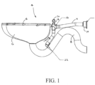
FIG. 1 is a side view of a toilet fixture according to one example of the present disclosure; -
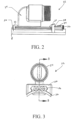
FIG. 2 is a side view of a jet assembly of the toilet fixture ofFIG. 1 according to one example of the present disclosure; -
FIG. 3 is a rear view of the jet assembly ofFIG. 2 ; -
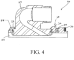
FIG. 4 is a cross-sectional view of the jet assembly ofFIG. 2 along line B-B; - The embodiments depicted in
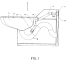
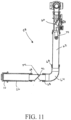
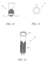
figures 5-14 are not comprised within the scope of protection conferred by the claims. - For purposes of the description hereinafter, spatial orientation terms, as used, shall relate to the referenced embodiment as it is oriented in the accompanying drawings, figures, or otherwise described in the following detailed description. However, it is to be understood that the embodiments described hereinafter may assume many alternative variations and configurations. It is also to be understood that the specific components, devices, features, and operational sequences illustrated in the accompanying drawings, figures, or otherwise described herein are simply exemplary and should not be considered as limiting.
- The present disclosure is directed to a toilet fixture with a clog prevention and cleanout arrangement. Certain preferred and nonlimiting examples of the components of the toilet fixture are illustrated in
FIGS. 1-4 . - With reference to
FIG. 1 , atoilet fixture 2 utilizing a clog prevention and cleanout arrangement is shown and described. Thetoilet fixture 2 includes aninlet pipe 4, a toilet bowl 6 and an outlet/waste pipe 8. Theinlet pipe 4 may include afitting ring 10 for connection to a flush assembly (not shown inFIG. 1 ) that is positioned behind a wall upon which thetoilet fixture 2 is anchored. Fluid from the flush assembly is directed to theinlet pipe 4 and into the toilet bowl 6. The toilet bowl 6 may be any type of toilet bowl generally known in the art. The toilet bowl 6 may include a plurality of flush rim rinse holes 12 defined in an upper edge of the toilet bowl 6. Waste and fluid from the toilet bowl 6 are flushed out of thetoilet fixture 2 through the outlet pipe 8. Theinlet pipe 4, the toilet bowl 6, and the waste pipe 8 may be made of stainless steel and may be pre-welded together before installation of thetoilet fixture 2 on the wall. - As discussed above, debris from the flush assembly may be directed to the
toilet fixture 2 via theinlet pipe 4. This debris may be directed into the toilet bowl 6, which can cause clogging of the toilet bowl 6, and/or may be directed through a jet pipe 14 that fluidly connects theinlet pipe 4 to the outlet pipe 8. The jet pipe 14 may also direct fluid from theinlet pipe 4 to the outlet pipe 8 to assist in flushing any waste or debris from the outlet pipe 8. The debris from the flush assembly, however, may begin to also clog in the outlet pipe 8. Therefore, in this example of thetoilet fixture 2, a fitting 16 is positioned in-line with theinlet pipe 4 and is connected to the jet pipe 14. The fitting 16 includes acleanout hole 18 that permits an individual to access the interior of theinlet pipe 4 and/or the jet pipe 14 to remove any debris that has been directed therethrough from the flush assembly. The fitting 16 may include a removable cap 20 to cover thecleanout hole 18. - With reference to
FIGS. 1-4 , thetoilet fixture 2 may also include ajet assembly 22 provided on an end of the jet pipe 14 and connected to the outlet pipe 8. Thejet assembly 22 may be removably connected to the jet pipe 14 and the outlet pipe 8 so that thejet assembly 22 can be easily removed from thetoilet fixture 2 to remove any debris that has built up within thejet assembly 22. Thejet assembly 22 includes ajet 24, a mounting base 26, and alocking mechanism 28. Thejet 24 defines a passageway to direct fluid from theinlet pipe 4 to the outlet pipe 8 and includes a first threaded end for connection to the jet pipe 14 and a flanged end for connection to the mounting base 26. The mounting base 26 may be welded or fastened to an outer surface of the outlet pipe 8. In another example, the mounting base 26 may be mechanically fastened according to any known technique for fastening two elements together, such as nuts and bolts, screws, clamps, and/or latches. Thejet 24 may be held on the mounting base 26 using thelocking mechanism 28. Thelocking mechanism 28 includes two lockingarms jet 24 between the mounting base 26 and thelocking mechanism 28. Onelocking arm 30 may be slidable relative to the mounting base 26 and onelocking arm 32 may be held stationary on the mounting base 26. Thelocking arm 30 may be spring-loaded into a lock position by a resilient member, such as aspring 34. An individual can move the lockingarm 34 to an open position by pushing the lockingarm 30 against thespring 34. As the lockingarm 30 is moved away from the lockingarm 34, an opening to receive thejet 24 is enlarged to permit an individual to remove or insert thejet 24. In the event thejet 24 is being inserted, upon release of the lockingarm 30, thespring 34 biases the lockingarm 30 back to the lock position to lock thejet 24 on the mounting base 26. Using thislocking mechanism 28, an individual can easily and efficiently remove and attach thejet 24 to the mounting base 26 to keep thejet 24 free of debris. In one example of the present disclosure, thejet assembly 22 also includes at least onescrew member 36 that can be used to adjust the biasing force of thespring 34 against the lockingarm 30. Thescrew member 36 can also be removed to allow complete removal of thejet 24. As shown inFIG. 4 , a sealinggasket 38 may be provided between the flanged end portion of thejet 24 and the mounting base 26 to ensure a leak-free connection between thejet 24 and the mounting base 26. The sealinggasket 38 may be made of an elastomer. - The invention described hereinabove is defined by the appended claims and all changes to the invention that fall within the meaning and range of equivalency of the claims are to be embraced within their scope.
Claims (6)
- A toilet fixture, comprising:a jet pipe (14) adapted to be placed in fluid communication with an inlet pipe (4) and an outlet pipe (8), wherein the inlet pipe (4) and the outlet pipe (8) are in fluid communication with a toilet bowl (6); anda removable jet pipe assembly (22) configured to selectively connect and disconnect the jet pipe (14) to the outlet pipe (8),wherein the removable jet pipe assembly (22) comprises:a mounting base (26) adapted to be positioned on the outlet pipe (8), anda jet (24) removably connected to the mounting base (26),wherein the removable jet pipe assembly (22) further comprises a locking mechanism (28) configured to remove the jet (24) from the mounting base (26) and/or attach the jet (24) to the mounting base (26), andcharacterized in thatthe locking mechanism (28) includes a pair of locking arms (32, 34) that hold the jet (24) to the mounting base (26).
- The toilet fixture as claimed in claim 1, wherein at least one of the locking arms (32, 34) is spring-biased to permit the locking arms (32, 34) to move relative to the mounting base (26) between a locked position and an unlocked position.
- The toilet fixture as claimed in claim 2, wherein the locking mechanism (28) further comprises at least one screw member (36) for adjusting a biasing force of the spring-biased locking arms (32, 34).
- The toilet fixture as claimed in claim 1, further comprising a fitting (16) provided in-line with the inlet pipe (4), wherein the fitting (16) is connected to the jet pipe (14).
- The toilet fixture as claimed in claim 4, wherein the fitting (16) includes a cleanout hole (18) that permits access to an interior space of the inlet pipe (4) and jet pipe (14).
- The toilet fixture of claim 1, further comprising:the inlet pipe (4);the toilet bowl (6) in fluid communication with the inlet pipe (4); andthe outlet pipe (8) in fluid communication with the toilet bowl (6).
Priority Applications (2)
| Application Number | Priority Date | Filing Date | Title |
|---|---|---|---|
| EP22202191.7A EP4148197A1 (en) | 2019-10-10 | 2020-10-09 | Toilet fixture clog prevention and cleanout |
| HRP20250881TT HRP20250881T1 (en) | 2019-10-10 | 2020-10-09 | PREVENTING CLOGGING AND CLEANING SANITARY EQUIPMENT |
Applications Claiming Priority (2)
| Application Number | Priority Date | Filing Date | Title |
|---|---|---|---|
| US201962913233P | 2019-10-10 | 2019-10-10 | |
| PCT/US2020/054954 WO2021072174A1 (en) | 2019-10-10 | 2020-10-09 | Toilet fixture clog prevention and cleanout |
Related Child Applications (2)
| Application Number | Title | Priority Date | Filing Date |
|---|---|---|---|
| EP22202191.7A Division-Into EP4148197A1 (en) | 2019-10-10 | 2020-10-09 | Toilet fixture clog prevention and cleanout |
| EP22202191.7A Division EP4148197A1 (en) | 2019-10-10 | 2020-10-09 | Toilet fixture clog prevention and cleanout |
Publications (3)
| Publication Number | Publication Date |
|---|---|
| EP4041958A1 EP4041958A1 (en) | 2022-08-17 |
| EP4041958A4 EP4041958A4 (en) | 2023-03-15 |
| EP4041958B1 true EP4041958B1 (en) | 2025-04-30 |
Family
ID=75382690
Family Applications (2)
| Application Number | Title | Priority Date | Filing Date |
|---|---|---|---|
| EP22202191.7A Pending EP4148197A1 (en) | 2019-10-10 | 2020-10-09 | Toilet fixture clog prevention and cleanout |
| EP20875060.4A Active EP4041958B1 (en) | 2019-10-10 | 2020-10-09 | PREVENTION AND CLEANING OF BLOCKAGES IN TOILET FITTINGS |
Family Applications Before (1)
| Application Number | Title | Priority Date | Filing Date |
|---|---|---|---|
| EP22202191.7A Pending EP4148197A1 (en) | 2019-10-10 | 2020-10-09 | Toilet fixture clog prevention and cleanout |
Country Status (9)
| Country | Link |
|---|---|
| US (3) | US11692338B2 (en) |
| EP (2) | EP4148197A1 (en) |
| JP (2) | JP7620334B2 (en) |
| AU (2) | AU2020361592B2 (en) |
| CA (1) | CA3152350A1 (en) |
| ES (1) | ES3034558T3 (en) |
| HR (1) | HRP20250881T1 (en) |
| MX (2) | MX428627B (en) |
| WO (1) | WO2021072174A1 (en) |
Families Citing this family (4)
| Publication number | Priority date | Publication date | Assignee | Title |
|---|---|---|---|---|
| JP7806441B2 (en) * | 2021-10-29 | 2026-01-27 | Toto株式会社 | flush toilet |
| US12674310B2 (en) * | 2023-03-01 | 2026-07-07 | Willoughby Industries Inc | Rotationally molded ligature resistant toilet |
| US12662804B2 (en) * | 2023-09-15 | 2026-06-23 | Acorn Engineering Company | Hybrid toilet |
| EP4589087A1 (en) * | 2024-01-19 | 2025-07-23 | Sanitea S.R.L. | Method for installing sanitary fixtures, method for reducing water leaks in the bowl, kit, and installation |
Family Cites Families (33)
| Publication number | Priority date | Publication date | Assignee | Title |
|---|---|---|---|---|
| US957709A (en) * | 1909-04-08 | 1910-05-10 | Hiram Phillips | Plumbing attachment. |
| US1755040A (en) * | 1929-04-17 | 1930-04-15 | Wallace Frank | Water-closet |
| US1817376A (en) | 1929-06-24 | 1931-08-04 | Izquierdo Angel | Drain strainer |
| US1928717A (en) * | 1932-09-26 | 1933-10-03 | Cesare C Campus | Siphon jet flushing nozzle, water closet, flushing valve, and bidet combination |
| US1998861A (en) | 1934-05-14 | 1935-04-23 | Cesare C Campus | Siphonproof flushometer and bowl combination |
| US3224013A (en) * | 1964-03-18 | 1965-12-21 | Elton H Tubbs | Siphonic flush commode |
| US3654641A (en) * | 1970-10-02 | 1972-04-11 | Fred Braun Sr | Toilet bowl structure |
| JPS51127335U (en) | 1975-04-10 | 1976-10-15 | ||
| US4164048A (en) * | 1977-12-30 | 1979-08-14 | Kampfer John H | Combination sink trap access port filtration device |
| US4250037A (en) * | 1979-03-28 | 1981-02-10 | Kempa John F | Plumbing fixture with integral strainer |
| DE8709163U1 (en) | 1987-07-03 | 1987-08-27 | Keramag Keramische Werke Ag, 4030 Ratingen | Device for connecting the under-shower of a hygienic toilet seat to the water supply network |
| US5067181A (en) * | 1990-03-13 | 1991-11-26 | Acorn Engineering Company | Blow out toilet with low water volume usage |
| US5502845A (en) * | 1991-06-10 | 1996-04-02 | Toto Ltd. | Siphon-jet flush water supply system for toilet stool |
| US5388610A (en) * | 1994-05-17 | 1995-02-14 | Chuang; Ming-Jung | Flush valve for urinals |
| US5525215A (en) * | 1995-05-08 | 1996-06-11 | Marchionda; Tony F. | Drain trap filter assembly |
| US5944991A (en) * | 1997-11-21 | 1999-08-31 | Dresser Industries, Inc. | Pipeline strainer |
| JP3191766B2 (en) * | 1998-06-10 | 2001-07-23 | 東陶機器株式会社 | Base plate for toilet device and toilet device including the same |
| EP1234921B1 (en) | 1999-11-29 | 2006-08-02 | Inax Corporation | Tankless toilet |
| US6494325B1 (en) * | 2000-10-23 | 2002-12-17 | Israel Mizrahi | Toilet water-line filter |
| US6308350B1 (en) * | 2000-11-09 | 2001-10-30 | Anthony F. Marchionda, Jr. | Drain trap filter assembly |
| US6662381B1 (en) | 2003-01-13 | 2003-12-16 | Elizabeth C. Powell | Automated toilet plunging apparatus |
| US6802424B2 (en) * | 2003-01-14 | 2004-10-12 | Globe Union Industrial Corp. | Strainer in shower bath tap valve |
| US6928666B1 (en) * | 2004-03-03 | 2005-08-16 | Richard C. Schaffer | Toilet with self-contained ventilation system |
| JP2006045775A (en) * | 2004-07-30 | 2006-02-16 | Inax Corp | Toilet bowl flushing method and toilet bowl flushing device |
| US20080244819A1 (en) * | 2006-04-06 | 2008-10-09 | David Meador | Self-plunging toilet and method of clearing a toilet |
| US8418277B2 (en) * | 2006-08-31 | 2013-04-16 | Toto Ltd. | Flush toilet |
| US7461410B1 (en) * | 2008-03-28 | 2008-12-09 | Shaffer Gene P | Toilet odor ventilating assembly |
| JP5700483B2 (en) | 2010-08-06 | 2015-04-15 | 株式会社Lixil | Toilet bowl cleaning device |
| KR101263756B1 (en) | 2011-08-31 | 2013-05-13 | 계림요업주식회사 | Water injector of green toilet which has multiple jets nozzle |
| US10465366B2 (en) * | 2014-05-27 | 2019-11-05 | As America, Inc. | Sanitaryware cleaning system |
| US10352028B2 (en) * | 2015-06-29 | 2019-07-16 | Acorn Engineering Company | Waste receptacle systems and methods |
| US9945111B1 (en) * | 2016-03-11 | 2018-04-17 | Challenge Llc | Toilet with easy access cleanout |
| CN109610589A (en) | 2018-12-15 | 2019-04-12 | 广东鹏美森木业科技有限公司 | self unclogging toilet |
-
2020
- 2020-10-09 ES ES20875060T patent/ES3034558T3/en active Active
- 2020-10-09 MX MX2022004165A patent/MX428627B/en unknown
- 2020-10-09 EP EP22202191.7A patent/EP4148197A1/en active Pending
- 2020-10-09 HR HRP20250881TT patent/HRP20250881T1/en unknown
- 2020-10-09 WO PCT/US2020/054954 patent/WO2021072174A1/en not_active Ceased
- 2020-10-09 EP EP20875060.4A patent/EP4041958B1/en active Active
- 2020-10-09 JP JP2022521424A patent/JP7620334B2/en active Active
- 2020-10-09 CA CA3152350A patent/CA3152350A1/en active Pending
- 2020-10-09 AU AU2020361592A patent/AU2020361592B2/en active Active
- 2020-10-09 US US17/067,214 patent/US11692338B2/en active Active
-
2022
- 2022-04-06 MX MX2025012272A patent/MX2025012272A/en unknown
-
2023
- 2023-05-23 US US18/322,215 patent/US12264463B2/en active Active
-
2024
- 2024-12-27 JP JP2024232748A patent/JP2025041965A/en active Pending
-
2025
- 2025-03-03 US US19/068,157 patent/US20250198137A1/en active Pending
-
2026
- 2026-03-19 AU AU2026202146A patent/AU2026202146A1/en active Pending
Also Published As
| Publication number | Publication date |
|---|---|
| WO2021072174A1 (en) | 2021-04-15 |
| ES3034558T3 (en) | 2025-08-19 |
| CA3152350A1 (en) | 2021-04-15 |
| HRP20250881T1 (en) | 2025-12-05 |
| EP4041958A4 (en) | 2023-03-15 |
| US11692338B2 (en) | 2023-07-04 |
| EP4148197A1 (en) | 2023-03-15 |
| JP2022551492A (en) | 2022-12-09 |
| US20250198137A1 (en) | 2025-06-19 |
| US20210108404A1 (en) | 2021-04-15 |
| JP2025041965A (en) | 2025-03-26 |
| US20230295912A1 (en) | 2023-09-21 |
| AU2020361592B2 (en) | 2026-01-08 |
| MX428627B (en) | 2025-11-13 |
| US12264463B2 (en) | 2025-04-01 |
| MX2022004165A (en) | 2022-05-02 |
| EP4041958A1 (en) | 2022-08-17 |
| AU2020361592A1 (en) | 2022-04-14 |
| MX2025012272A (en) | 2025-11-03 |
| JP7620334B2 (en) | 2025-01-23 |
| AU2026202146A1 (en) | 2026-04-09 |
Similar Documents
| Publication | Publication Date | Title |
|---|---|---|
| US12264463B2 (en) | Toilet fixture clog prevention and cleanout | |
| US10087610B2 (en) | Devices, systems, and methods for automated drain jetting | |
| US20140366256A1 (en) | Flexible Toilet Seal Adaptable to Conduits of Different Size and Related Method | |
| US7270144B2 (en) | Universal washing machine outlet box | |
| US11725371B2 (en) | Sink basin drain assembly | |
| US20150275488A1 (en) | Circular galley drain strainer | |
| US7373674B1 (en) | Tub spout installation system | |
| GB2425818A (en) | Set of components for the modular construction of an outlet assembly | |
| US9765505B2 (en) | Air-gap faucet | |
| KR20170000017A (en) | A drain valve for outdoor fire hydrant and mounting structure thereof | |
| US9856991B2 (en) | Flush cap for a valve assembly | |
| CA2514386C (en) | Escutcheon for wall mounted faucets and hydrants | |
| US9758956B2 (en) | Flushing device | |
| EP1516969B1 (en) | Removable device for opening and closing sanitary fittings outlets | |
| JP3531056B2 (en) | Flush faucet | |
| JPH09189062A (en) | Hand-washing equipment for the toilet bowl | |
| US20230323647A1 (en) | Insert | |
| US20060283502A1 (en) | Air gap fitting | |
| EP2412878A1 (en) | A trap assembly and a lavatory comprising said trap assembly | |
| WO2019211648A1 (en) | Waterless waste valve | |
| JP2001062372A (en) | Lining jig and lining method for water pipe inner surface | |
| JP2002054194A (en) | Flush faucet |
Legal Events
| Date | Code | Title | Description |
|---|---|---|---|
| REG | Reference to a national code |
Ref country code: HR Ref legal event code: TUEP Ref document number: P20250881T Country of ref document: HR |
|
| STAA | Information on the status of an ep patent application or granted ep patent |
Free format text: STATUS: THE INTERNATIONAL PUBLICATION HAS BEEN MADE |
|
| PUAI | Public reference made under article 153(3) epc to a published international application that has entered the european phase |
Free format text: ORIGINAL CODE: 0009012 |
|
| STAA | Information on the status of an ep patent application or granted ep patent |
Free format text: STATUS: REQUEST FOR EXAMINATION WAS MADE |
|
| 17P | Request for examination filed |
Effective date: 20220503 |
|
| AK | Designated contracting states |
Kind code of ref document: A1 Designated state(s): AL AT BE BG CH CY CZ DE DK EE ES FI FR GB GR HR HU IE IS IT LI LT LU LV MC MK MT NL NO PL PT RO RS SE SI SK SM TR |
|
| DAV | Request for validation of the european patent (deleted) | ||
| DAX | Request for extension of the european patent (deleted) | ||
| REG | Reference to a national code |
Ref country code: DE Ref legal event code: R079 Free format text: PREVIOUS MAIN CLASS: E03D0003100000 Ipc: E03D0011130000 Ref country code: DE Ref legal event code: R079 Ref document number: 602020050599 Country of ref document: DE Free format text: PREVIOUS MAIN CLASS: E03D0003100000 Ipc: E03D0011130000 |
|
| A4 | Supplementary search report drawn up and despatched |
Effective date: 20230213 |
|
| RIC1 | Information provided on ipc code assigned before grant |
Ipc: E03D 3/00 20060101ALI20230207BHEP Ipc: E03D 11/13 20060101AFI20230207BHEP |
|
| GRAP | Despatch of communication of intention to grant a patent |
Free format text: ORIGINAL CODE: EPIDOSNIGR1 |
|
| STAA | Information on the status of an ep patent application or granted ep patent |
Free format text: STATUS: GRANT OF PATENT IS INTENDED |
|
| INTG | Intention to grant announced |
Effective date: 20241126 |
|
| GRAS | Grant fee paid |
Free format text: ORIGINAL CODE: EPIDOSNIGR3 |
|
| GRAA | (expected) grant |
Free format text: ORIGINAL CODE: 0009210 |
|
| STAA | Information on the status of an ep patent application or granted ep patent |
Free format text: STATUS: THE PATENT HAS BEEN GRANTED |
|
| AK | Designated contracting states |
Kind code of ref document: B1 Designated state(s): AL AT BE BG CH CY CZ DE DK EE ES FI FR GB GR HR HU IE IS IT LI LT LU LV MC MK MT NL NO PL PT RO RS SE SI SK SM TR |
|
| REG | Reference to a national code |
Ref country code: CH Ref legal event code: EP Ref country code: GB Ref legal event code: FG4D |
|
| REG | Reference to a national code |
Ref country code: IE Ref legal event code: FG4D |
|
| REG | Reference to a national code |
Ref country code: DE Ref legal event code: R096 Ref document number: 602020050599 Country of ref document: DE |
|
| REG | Reference to a national code |
Ref country code: ES Ref legal event code: FG2A Ref document number: 3034558 Country of ref document: ES Kind code of ref document: T3 Effective date: 20250819 |
|
| REG | Reference to a national code |
Ref country code: NL Ref legal event code: MP Effective date: 20250430 |
|
| REG | Reference to a national code |
Ref country code: AT Ref legal event code: MK05 Ref document number: 1790129 Country of ref document: AT Kind code of ref document: T Effective date: 20250430 |
|
| PG25 | Lapsed in a contracting state [announced via postgrant information from national office to epo] |
Ref country code: FI Free format text: LAPSE BECAUSE OF FAILURE TO SUBMIT A TRANSLATION OF THE DESCRIPTION OR TO PAY THE FEE WITHIN THE PRESCRIBED TIME-LIMIT Effective date: 20250430 Ref country code: PT Free format text: LAPSE BECAUSE OF FAILURE TO SUBMIT A TRANSLATION OF THE DESCRIPTION OR TO PAY THE FEE WITHIN THE PRESCRIBED TIME-LIMIT Effective date: 20250901 |
|
| REG | Reference to a national code |
Ref country code: LT Ref legal event code: MG9D |
|
| PG25 | Lapsed in a contracting state [announced via postgrant information from national office to epo] |
Ref country code: GR Free format text: LAPSE BECAUSE OF FAILURE TO SUBMIT A TRANSLATION OF THE DESCRIPTION OR TO PAY THE FEE WITHIN THE PRESCRIBED TIME-LIMIT Effective date: 20250731 Ref country code: NO Free format text: LAPSE BECAUSE OF FAILURE TO SUBMIT A TRANSLATION OF THE DESCRIPTION OR TO PAY THE FEE WITHIN THE PRESCRIBED TIME-LIMIT Effective date: 20250730 |
|
| PG25 | Lapsed in a contracting state [announced via postgrant information from national office to epo] |
Ref country code: NL Free format text: LAPSE BECAUSE OF FAILURE TO SUBMIT A TRANSLATION OF THE DESCRIPTION OR TO PAY THE FEE WITHIN THE PRESCRIBED TIME-LIMIT Effective date: 20250430 Ref country code: PL Free format text: LAPSE BECAUSE OF FAILURE TO SUBMIT A TRANSLATION OF THE DESCRIPTION OR TO PAY THE FEE WITHIN THE PRESCRIBED TIME-LIMIT Effective date: 20250430 |
|
| PG25 | Lapsed in a contracting state [announced via postgrant information from national office to epo] |
Ref country code: BG Free format text: LAPSE BECAUSE OF FAILURE TO SUBMIT A TRANSLATION OF THE DESCRIPTION OR TO PAY THE FEE WITHIN THE PRESCRIBED TIME-LIMIT Effective date: 20250430 |
|
| PG25 | Lapsed in a contracting state [announced via postgrant information from national office to epo] |
Ref country code: AT Free format text: LAPSE BECAUSE OF FAILURE TO SUBMIT A TRANSLATION OF THE DESCRIPTION OR TO PAY THE FEE WITHIN THE PRESCRIBED TIME-LIMIT Effective date: 20250430 |
|
| PG25 | Lapsed in a contracting state [announced via postgrant information from national office to epo] |
Ref country code: RS Free format text: LAPSE BECAUSE OF FAILURE TO SUBMIT A TRANSLATION OF THE DESCRIPTION OR TO PAY THE FEE WITHIN THE PRESCRIBED TIME-LIMIT Effective date: 20250731 |
|
| PG25 | Lapsed in a contracting state [announced via postgrant information from national office to epo] |
Ref country code: IS Free format text: LAPSE BECAUSE OF FAILURE TO SUBMIT A TRANSLATION OF THE DESCRIPTION OR TO PAY THE FEE WITHIN THE PRESCRIBED TIME-LIMIT Effective date: 20250830 |
|
| PG25 | Lapsed in a contracting state [announced via postgrant information from national office to epo] |
Ref country code: LV Free format text: LAPSE BECAUSE OF FAILURE TO SUBMIT A TRANSLATION OF THE DESCRIPTION OR TO PAY THE FEE WITHIN THE PRESCRIBED TIME-LIMIT Effective date: 20250430 |
|
| REG | Reference to a national code |
Ref country code: HR Ref legal event code: ODRP Ref document number: P20250881T Country of ref document: HR Payment date: 20251001 Year of fee payment: 6 |
|
| REG | Reference to a national code |
Ref country code: HR Ref legal event code: T1PR Ref document number: P20250881 Country of ref document: HR |
|
| PGFP | Annual fee paid to national office [announced via postgrant information from national office to epo] |
Ref country code: DE Payment date: 20251029 Year of fee payment: 6 |
|
| PGFP | Annual fee paid to national office [announced via postgrant information from national office to epo] |
Ref country code: GB Payment date: 20251027 Year of fee payment: 6 |
|
| PG25 | Lapsed in a contracting state [announced via postgrant information from national office to epo] |
Ref country code: DK Free format text: LAPSE BECAUSE OF FAILURE TO SUBMIT A TRANSLATION OF THE DESCRIPTION OR TO PAY THE FEE WITHIN THE PRESCRIBED TIME-LIMIT Effective date: 20250430 Ref country code: SM Free format text: LAPSE BECAUSE OF FAILURE TO SUBMIT A TRANSLATION OF THE DESCRIPTION OR TO PAY THE FEE WITHIN THE PRESCRIBED TIME-LIMIT Effective date: 20250430 |
|
| PGFP | Annual fee paid to national office [announced via postgrant information from national office to epo] |
Ref country code: IT Payment date: 20251021 Year of fee payment: 6 |
|
| PGFP | Annual fee paid to national office [announced via postgrant information from national office to epo] |
Ref country code: FR Payment date: 20251027 Year of fee payment: 6 Ref country code: HR Payment date: 20251001 Year of fee payment: 6 |
|
| PG25 | Lapsed in a contracting state [announced via postgrant information from national office to epo] |
Ref country code: CZ Free format text: LAPSE BECAUSE OF FAILURE TO SUBMIT A TRANSLATION OF THE DESCRIPTION OR TO PAY THE FEE WITHIN THE PRESCRIBED TIME-LIMIT Effective date: 20250430 |
|
| PG25 | Lapsed in a contracting state [announced via postgrant information from national office to epo] |
Ref country code: EE Free format text: LAPSE BECAUSE OF FAILURE TO SUBMIT A TRANSLATION OF THE DESCRIPTION OR TO PAY THE FEE WITHIN THE PRESCRIBED TIME-LIMIT Effective date: 20250430 |
|
| PG25 | Lapsed in a contracting state [announced via postgrant information from national office to epo] |
Ref country code: SK Free format text: LAPSE BECAUSE OF FAILURE TO SUBMIT A TRANSLATION OF THE DESCRIPTION OR TO PAY THE FEE WITHIN THE PRESCRIBED TIME-LIMIT Effective date: 20250430 |
|
| PGFP | Annual fee paid to national office [announced via postgrant information from national office to epo] |
Ref country code: ES Payment date: 20251103 Year of fee payment: 6 |
|
| REG | Reference to a national code |
Ref country code: DE Ref legal event code: R097 Ref document number: 602020050599 Country of ref document: DE |
|
| PG25 | Lapsed in a contracting state [announced via postgrant information from national office to epo] |
Ref country code: RO Free format text: LAPSE BECAUSE OF FAILURE TO SUBMIT A TRANSLATION OF THE DESCRIPTION OR TO PAY THE FEE WITHIN THE PRESCRIBED TIME-LIMIT Effective date: 20250430 |
|
| PLBE | No opposition filed within time limit |
Free format text: ORIGINAL CODE: 0009261 |
|
| STAA | Information on the status of an ep patent application or granted ep patent |
Free format text: STATUS: NO OPPOSITION FILED WITHIN TIME LIMIT |
|
| REG | Reference to a national code |
Ref country code: CH Ref legal event code: L10 Free format text: ST27 STATUS EVENT CODE: U-0-0-L10-L00 (AS PROVIDED BY THE NATIONAL OFFICE) Effective date: 20260311 |
|
| 26N | No opposition filed |
Effective date: 20260202 |
|
| REG | Reference to a national code |
Ref country code: CH Ref legal event code: H13 Free format text: ST27 STATUS EVENT CODE: U-0-0-H10-H13 (AS PROVIDED BY THE NATIONAL OFFICE) Effective date: 20260527 |
|
| PG25 | Lapsed in a contracting state [announced via postgrant information from national office to epo] |
Ref country code: LU Free format text: LAPSE BECAUSE OF NON-PAYMENT OF DUE FEES Effective date: 20251009 |
|
| REG | Reference to a national code |
Ref country code: BE Ref legal event code: MM Effective date: 20251031 |
|
| PG25 | Lapsed in a contracting state [announced via postgrant information from national office to epo] |
Ref country code: LT Free format text: LAPSE BECAUSE OF FAILURE TO SUBMIT A TRANSLATION OF THE DESCRIPTION OR TO PAY THE FEE WITHIN THE PRESCRIBED TIME-LIMIT Effective date: 20250430 |
|
| PG25 | Lapsed in a contracting state [announced via postgrant information from national office to epo] |
Ref country code: MC Free format text: LAPSE BECAUSE OF FAILURE TO SUBMIT A TRANSLATION OF THE DESCRIPTION OR TO PAY THE FEE WITHIN THE PRESCRIBED TIME-LIMIT Effective date: 20250430 |
|
| PG25 | Lapsed in a contracting state [announced via postgrant information from national office to epo] |
Ref country code: BE Free format text: LAPSE BECAUSE OF NON-PAYMENT OF DUE FEES Effective date: 20251031 Ref country code: CH Free format text: LAPSE BECAUSE OF NON-PAYMENT OF DUE FEES Effective date: 20251031 |
|
| PG25 | Lapsed in a contracting state [announced via postgrant information from national office to epo] |
Ref country code: SE Free format text: LAPSE BECAUSE OF FAILURE TO SUBMIT A TRANSLATION OF THE DESCRIPTION OR TO PAY THE FEE WITHIN THE PRESCRIBED TIME-LIMIT Effective date: 20250430 |