EP4041155B1 - Apparatuses and methods for negative pressure wound therapy - Google Patents
Apparatuses and methods for negative pressure wound therapy Download PDFInfo
- Publication number
- EP4041155B1 EP4041155B1 EP20786501.5A EP20786501A EP4041155B1 EP 4041155 B1 EP4041155 B1 EP 4041155B1 EP 20786501 A EP20786501 A EP 20786501A EP 4041155 B1 EP4041155 B1 EP 4041155B1
- Authority
- EP
- European Patent Office
- Prior art keywords
- layer
- wound
- negative pressure
- dressing
- drape
- Prior art date
- Legal status (The legal status is an assumption and is not a legal conclusion. Google has not performed a legal analysis and makes no representation as to the accuracy of the status listed.)
- Active
Links
Images








Classifications
-
- A—HUMAN NECESSITIES
- A61—MEDICAL OR VETERINARY SCIENCE; HYGIENE
- A61M—DEVICES FOR INTRODUCING MEDIA INTO, OR ONTO, THE BODY; DEVICES FOR TRANSDUCING BODY MEDIA OR FOR TAKING MEDIA FROM THE BODY; DEVICES FOR PRODUCING OR ENDING SLEEP OR STUPOR
- A61M1/00—Suction or pumping devices for medical purposes; Devices for carrying-off, for treatment of, or for carrying-over, body-liquids; Drainage systems
- A61M1/90—Negative pressure wound therapy devices, i.e. devices for applying suction to a wound to promote healing, e.g. including a vacuum dressing
- A61M1/91—Suction aspects of the dressing
-
- A—HUMAN NECESSITIES
- A61—MEDICAL OR VETERINARY SCIENCE; HYGIENE
- A61F—FILTERS IMPLANTABLE INTO BLOOD VESSELS; PROSTHESES; DEVICES PROVIDING PATENCY TO, OR PREVENTING COLLAPSING OF, TUBULAR STRUCTURES OF THE BODY, e.g. STENTS; ORTHOPAEDIC, NURSING OR CONTRACEPTIVE DEVICES; FOMENTATION; TREATMENT OR PROTECTION OF EYES OR EARS; BANDAGES, DRESSINGS OR ABSORBENT PADS; FIRST-AID KITS
- A61F13/00—Bandages or dressings; Absorbent pads
-
- A—HUMAN NECESSITIES
- A61—MEDICAL OR VETERINARY SCIENCE; HYGIENE
- A61F—FILTERS IMPLANTABLE INTO BLOOD VESSELS; PROSTHESES; DEVICES PROVIDING PATENCY TO, OR PREVENTING COLLAPSING OF, TUBULAR STRUCTURES OF THE BODY, e.g. STENTS; ORTHOPAEDIC, NURSING OR CONTRACEPTIVE DEVICES; FOMENTATION; TREATMENT OR PROTECTION OF EYES OR EARS; BANDAGES, DRESSINGS OR ABSORBENT PADS; FIRST-AID KITS
- A61F13/00—Bandages or dressings; Absorbent pads
- A61F13/02—Adhesive bandages or dressings
-
- A—HUMAN NECESSITIES
- A61—MEDICAL OR VETERINARY SCIENCE; HYGIENE
- A61F—FILTERS IMPLANTABLE INTO BLOOD VESSELS; PROSTHESES; DEVICES PROVIDING PATENCY TO, OR PREVENTING COLLAPSING OF, TUBULAR STRUCTURES OF THE BODY, e.g. STENTS; ORTHOPAEDIC, NURSING OR CONTRACEPTIVE DEVICES; FOMENTATION; TREATMENT OR PROTECTION OF EYES OR EARS; BANDAGES, DRESSINGS OR ABSORBENT PADS; FIRST-AID KITS
- A61F13/00—Bandages or dressings; Absorbent pads
- A61F13/02—Adhesive bandages or dressings
- A61F13/0203—Adhesive bandages or dressings with fluid retention members
- A61F13/0206—Adhesive bandages or dressings with fluid retention members with absorbent fibrous layers, e.g. woven or non-woven absorbent pads or island dressings
-
- A—HUMAN NECESSITIES
- A61—MEDICAL OR VETERINARY SCIENCE; HYGIENE
- A61F—FILTERS IMPLANTABLE INTO BLOOD VESSELS; PROSTHESES; DEVICES PROVIDING PATENCY TO, OR PREVENTING COLLAPSING OF, TUBULAR STRUCTURES OF THE BODY, e.g. STENTS; ORTHOPAEDIC, NURSING OR CONTRACEPTIVE DEVICES; FOMENTATION; TREATMENT OR PROTECTION OF EYES OR EARS; BANDAGES, DRESSINGS OR ABSORBENT PADS; FIRST-AID KITS
- A61F13/00—Bandages or dressings; Absorbent pads
- A61F13/02—Adhesive bandages or dressings
- A61F13/023—Adhesive bandages or dressings wound covering film layers without a fluid retention layer
-
- A—HUMAN NECESSITIES
- A61—MEDICAL OR VETERINARY SCIENCE; HYGIENE
- A61F—FILTERS IMPLANTABLE INTO BLOOD VESSELS; PROSTHESES; DEVICES PROVIDING PATENCY TO, OR PREVENTING COLLAPSING OF, TUBULAR STRUCTURES OF THE BODY, e.g. STENTS; ORTHOPAEDIC, NURSING OR CONTRACEPTIVE DEVICES; FOMENTATION; TREATMENT OR PROTECTION OF EYES OR EARS; BANDAGES, DRESSINGS OR ABSORBENT PADS; FIRST-AID KITS
- A61F13/00—Bandages or dressings; Absorbent pads
- A61F13/05—Bandages or dressings; Absorbent pads specially adapted for use with sub-pressure or over-pressure therapy, wound drainage or wound irrigation, e.g. for use with negative-pressure wound therapy [NPWT]
-
- A—HUMAN NECESSITIES
- A61—MEDICAL OR VETERINARY SCIENCE; HYGIENE
- A61M—DEVICES FOR INTRODUCING MEDIA INTO, OR ONTO, THE BODY; DEVICES FOR TRANSDUCING BODY MEDIA OR FOR TAKING MEDIA FROM THE BODY; DEVICES FOR PRODUCING OR ENDING SLEEP OR STUPOR
- A61M1/00—Suction or pumping devices for medical purposes; Devices for carrying-off, for treatment of, or for carrying-over, body-liquids; Drainage systems
- A61M1/90—Negative pressure wound therapy devices, i.e. devices for applying suction to a wound to promote healing, e.g. including a vacuum dressing
- A61M1/91—Suction aspects of the dressing
- A61M1/915—Constructional details of the pressure distribution manifold
-
- A—HUMAN NECESSITIES
- A61—MEDICAL OR VETERINARY SCIENCE; HYGIENE
- A61M—DEVICES FOR INTRODUCING MEDIA INTO, OR ONTO, THE BODY; DEVICES FOR TRANSDUCING BODY MEDIA OR FOR TAKING MEDIA FROM THE BODY; DEVICES FOR PRODUCING OR ENDING SLEEP OR STUPOR
- A61M1/00—Suction or pumping devices for medical purposes; Devices for carrying-off, for treatment of, or for carrying-over, body-liquids; Drainage systems
- A61M1/90—Negative pressure wound therapy devices, i.e. devices for applying suction to a wound to promote healing, e.g. including a vacuum dressing
- A61M1/96—Suction control thereof
-
- A—HUMAN NECESSITIES
- A61—MEDICAL OR VETERINARY SCIENCE; HYGIENE
- A61M—DEVICES FOR INTRODUCING MEDIA INTO, OR ONTO, THE BODY; DEVICES FOR TRANSDUCING BODY MEDIA OR FOR TAKING MEDIA FROM THE BODY; DEVICES FOR PRODUCING OR ENDING SLEEP OR STUPOR
- A61M1/00—Suction or pumping devices for medical purposes; Devices for carrying-off, for treatment of, or for carrying-over, body-liquids; Drainage systems
- A61M1/90—Negative pressure wound therapy devices, i.e. devices for applying suction to a wound to promote healing, e.g. including a vacuum dressing
- A61M1/96—Suction control thereof
- A61M1/962—Suction control thereof having pumping means on the suction site, e.g. miniature pump on dressing or dressing capable of exerting suction
-
- A—HUMAN NECESSITIES
- A61—MEDICAL OR VETERINARY SCIENCE; HYGIENE
- A61M—DEVICES FOR INTRODUCING MEDIA INTO, OR ONTO, THE BODY; DEVICES FOR TRANSDUCING BODY MEDIA OR FOR TAKING MEDIA FROM THE BODY; DEVICES FOR PRODUCING OR ENDING SLEEP OR STUPOR
- A61M1/00—Suction or pumping devices for medical purposes; Devices for carrying-off, for treatment of, or for carrying-over, body-liquids; Drainage systems
- A61M1/90—Negative pressure wound therapy devices, i.e. devices for applying suction to a wound to promote healing, e.g. including a vacuum dressing
- A61M1/96—Suction control thereof
- A61M1/964—Suction control thereof having venting means on or near the dressing
-
- A—HUMAN NECESSITIES
- A61—MEDICAL OR VETERINARY SCIENCE; HYGIENE
- A61M—DEVICES FOR INTRODUCING MEDIA INTO, OR ONTO, THE BODY; DEVICES FOR TRANSDUCING BODY MEDIA OR FOR TAKING MEDIA FROM THE BODY; DEVICES FOR PRODUCING OR ENDING SLEEP OR STUPOR
- A61M1/00—Suction or pumping devices for medical purposes; Devices for carrying-off, for treatment of, or for carrying-over, body-liquids; Drainage systems
- A61M1/90—Negative pressure wound therapy devices, i.e. devices for applying suction to a wound to promote healing, e.g. including a vacuum dressing
- A61M1/91—Suction aspects of the dressing
- A61M1/912—Connectors between dressing and drainage tube
-
- A—HUMAN NECESSITIES
- A61—MEDICAL OR VETERINARY SCIENCE; HYGIENE
- A61M—DEVICES FOR INTRODUCING MEDIA INTO, OR ONTO, THE BODY; DEVICES FOR TRANSDUCING BODY MEDIA OR FOR TAKING MEDIA FROM THE BODY; DEVICES FOR PRODUCING OR ENDING SLEEP OR STUPOR
- A61M1/00—Suction or pumping devices for medical purposes; Devices for carrying-off, for treatment of, or for carrying-over, body-liquids; Drainage systems
- A61M1/90—Negative pressure wound therapy devices, i.e. devices for applying suction to a wound to promote healing, e.g. including a vacuum dressing
- A61M1/91—Suction aspects of the dressing
- A61M1/912—Connectors between dressing and drainage tube
- A61M1/913—Connectors between dressing and drainage tube having a bridging element for transferring the reduced pressure from the connector to the dressing
-
- A—HUMAN NECESSITIES
- A61—MEDICAL OR VETERINARY SCIENCE; HYGIENE
- A61M—DEVICES FOR INTRODUCING MEDIA INTO, OR ONTO, THE BODY; DEVICES FOR TRANSDUCING BODY MEDIA OR FOR TAKING MEDIA FROM THE BODY; DEVICES FOR PRODUCING OR ENDING SLEEP OR STUPOR
- A61M1/00—Suction or pumping devices for medical purposes; Devices for carrying-off, for treatment of, or for carrying-over, body-liquids; Drainage systems
- A61M1/90—Negative pressure wound therapy devices, i.e. devices for applying suction to a wound to promote healing, e.g. including a vacuum dressing
- A61M1/98—Containers specifically adapted for negative pressure wound therapy
- A61M1/984—Containers specifically adapted for negative pressure wound therapy portable on the body
-
- A—HUMAN NECESSITIES
- A61—MEDICAL OR VETERINARY SCIENCE; HYGIENE
- A61M—DEVICES FOR INTRODUCING MEDIA INTO, OR ONTO, THE BODY; DEVICES FOR TRANSDUCING BODY MEDIA OR FOR TAKING MEDIA FROM THE BODY; DEVICES FOR PRODUCING OR ENDING SLEEP OR STUPOR
- A61M2205/00—General characteristics of the apparatus
- A61M2205/75—General characteristics of the apparatus with filters
- A61M2205/7509—General characteristics of the apparatus with filters for virus
-
- A—HUMAN NECESSITIES
- A61—MEDICAL OR VETERINARY SCIENCE; HYGIENE
- A61M—DEVICES FOR INTRODUCING MEDIA INTO, OR ONTO, THE BODY; DEVICES FOR TRANSDUCING BODY MEDIA OR FOR TAKING MEDIA FROM THE BODY; DEVICES FOR PRODUCING OR ENDING SLEEP OR STUPOR
- A61M2205/00—General characteristics of the apparatus
- A61M2205/75—General characteristics of the apparatus with filters
- A61M2205/7518—General characteristics of the apparatus with filters bacterial
Definitions
- the present disclosure relates to systems for negative pressure wound therapy.
- TNP therapy sometimes referred to as vacuum assisted closure, negative pressure wound therapy (NPWT), or reduced pressure wound therapy, is widely recognized as a beneficial mechanism for improving the healing rate of a wound.
- NNPWT negative pressure wound therapy
- Such therapy is applicable to a broad range of wounds such as incisional wounds, open wounds and abdominal wounds or the like.
- TNP therapy assists in the closure and healing of wounds by reducing tissue oedema, encouraging blood flow, stimulating the formation of granulation tissue, removing excess exudates and may reduce bacterial load and, thus, infection to the wound. Furthermore, TNP therapy permits less outside disturbance of the wound and promotes more rapid healing.
- a wound may initially contain and generate larger amounts of exudate, and the treatment may start with a system including a larger pump and a canister for the collection of greater volumes of wound exudate. As the healing progresses and less exudate is produced, the patient may be switched to a smaller disposable/portable device.
- WO2017/186771 relates to a system for negative pressure wound therapy.
- a drape comprising:
- the wound contact layer carries an adhesive portion on a lower surface thereof, the adhesive portion for forming a substantially fluid tight seal over a wound site.
- the wound contact layer may be perforated.
- the cover layer is moisture vapor permeable.
- the support layer comprises polypropylene, polyethylene terephthalate, or polyvinyl chloride.
- the support layer may be positioned above the spacer layer.
- the support layer may have greater stiffness than the cover layer.
- the support layer may comprise one or more perforations formed through a thickness of the support layer.
- the support layer may be positioned immediately below the cover layer, such that a portion of the support layer under the opening is exposed.
- the system may further comprise a suction adapter having an applicator at a distal end of the suction adapter, wherein at least a portion of the applicator is configured to be attached to the exposed portion of the support layer when the suction adapter is coupled to the drape and form a fluid tight seal.
- a proximal end of the suction adapter is configured to be fluidically connected to a source of negative pressure.
- the drape further comprises a reinforcement member positioned above the cover layer. The reinforcement member may be attached to an upper surface of the cover layer using an adhesive. The reinforcement member may comprise a window formed through the reinforcement layer, wherein the window is configured to expose the opening of the cover layer when the reinforcement member is attached to the cover layer.
- the reinforcement member may comprise a material stiffer than the cover layer.
- the system may further comprise a wound dressing, wherein at least a portion of the wound dressing is configured to be attached to the reinforcement member and coupled to the drape.
- An outer perimeter of the wound dressing may substantially conform to an outer perimeter of the reinforcement layer.
- the cover layer is sealed to the wound contact layer in a border region around the circumference of the drape.
- the support layer may be smaller than the spacer layer.
- Embodiments disclosed herein relate to apparatuses, systems, devices of treating a wound with reduced pressure.
- reduced or negative pressure levels such as -X mmHg
- a negative pressure value of -X mmHg reflects absolute pressure that is X mmHg below 760 mmHg or, in other words, an absolute pressure of (760-X) mmHg.
- negative pressure that is "less” or “smaller” than X mmHg corresponds to pressure that is closer to atmospheric pressure (e.g., -40 mmHg is less than - 60 mmHg).
- Negative pressure that is "more” or “greater” than -X mmHg corresponds to pressure that is further from atmospheric pressure (e.g., -80 mmHg is more than -60 mmHg).
- local ambient atmospheric pressure is used as a reference point, and such local atmospheric pressure may not necessarily be, for example, 760 mmHg.
- Embodiments of the present disclosure are generally applicable to use in topical negative pressure (TNP) or reduced pressure therapy systems.
- TNP topical negative pressure
- negative pressure wound therapy assists in the closure and healing of many forms of "hard to heal" wounds by reducing tissue oedema, encouraging blood flow and granular tissue formation, or removing excess exudate and can reduce bacterial load (and thus infection risk).
- the therapy allows for less disturbance of a wound leading to more rapid healing.
- TNP therapy systems can also assist in the healing of surgically closed wounds by removing fluid.
- TNP therapy helps to stabilize the tissue in the apposed position of closure.
- a further beneficial use of TNP therapy can be found in grafts and flaps where removal of excess fluid is important and close proximity of the graft to tissue is required in order to ensure tissue viability.
- Fig. 1 illustrates an embodiment of a negative or reduced pressure wound treatment (or TNP) system 100 including a wound filler 130 placed inside a wound cavity 110, the wound cavity sealed by a wound cover 120.
- the wound filler 130 in combination with the wound cover 120 can be referred to as wound dressing.
- a flow path 140 such as a single or multi lumen tube or conduit, is connected to the wound cover 120 with a negative pressure wound therapy device, for example pump assembly 150, configured to supply reduced pressure.
- the wound cover 120 can be in fluidic communication with the wound cavity 110.
- the pump assembly can be a canisterless pump assembly (meaning that exudate is collected in the wound dressing or is transferred via tube 140 for collection to another location).
- any of the pump assembly embodiments disclosed herein can be configured to include or support a canister. Additionally, in any of the system embodiments disclosed herein, any of the pump assembly embodiments can be mounted to or supported by the dressing, or adjacent to the dressing.
- the wound filler 130 can be any suitable type, such as hydrophilic or hydrophobic foam, gauze, inflatable bag, and so on.
- the wound filler 130 can be conformable to the wound cavity 110 such that it substantially fills the cavity.
- the wound cover 120 can provide a substantially fluid impermeable seal over the wound cavity 110.
- the wound cover 120 can have a top side and a bottom side, and the bottom side adhesively (or in any other suitable manner) seals with wound cavity 110.
- the conduit 140 or lumen or any other conduit or lumen disclosed herein can be formed from polyurethane, PVC, nylon, polyethylene, silicone, or any other suitable material.
- the wound cover 120 can have a port (not shown) configured to receive an end of the conduit 140.
- the conduit 140 can otherwise pass through or under the wound cover 120 to supply reduced pressure to the wound cavity 110 so as to maintain a desired level of reduced pressure in the wound cavity.
- the conduit 140 can be any suitable article configured to provide at least a substantially sealed fluid flow pathway between the pump assembly 150 and the wound cover 120, so as to supply the reduced pressure provided by the pump assembly 150 to wound cavity 110.
- the wound cover 120 and the wound filler 130 can be provided as a single article or an integrated single unit. In some embodiments, no wound filler is provided and the wound cover by itself may be considered the wound dressing.
- the wound dressing may then be connected, via the conduit 140, to a source of negative pressure, such as the pump assembly 150.
- the pump assembly 150 can be miniaturized and portable, although larger conventional pumps such can also be used.
- the wound cover 120 can be located over a wound site to be treated.
- the wound cover 120 can form a substantially sealed cavity or enclosure over the wound site.
- the wound cover 120 can be configured to have a film having a high water vapour permeability to enable the evaporation of surplus fluid, and can have a superabsorbing material contained therein to safely absorb wound exudate.
- a wound it is to be understood that the term wound is to be broadly construed and encompasses open and closed wounds in which skin is torn, cut or punctured or where trauma causes a contusion, or any other surficial or other conditions or imperfections on the skin of a patient or otherwise that benefit from reduced pressure treatment.
- a wound is thus broadly defined as any damaged region of tissue where fluid may or may not be produced.
- wounds include, but are not limited to, acute wounds, chronic wounds, surgical incisions and other incisions, subacute and dehisced wounds, traumatic wounds, flaps and skin grafts, lacerations, abrasions, contusions, burns, diabetic ulcers, pressure ulcers, stoma, surgical wounds, trauma and venous ulcers or the like.
- the components of the TNP system described herein can be particularly suited for incisional wounds that exude a small amount of wound exudate.
- Some embodiments of the system are designed to operate without the use of an exudate canister. Some embodiments can be configured to support an exudate canister. In some embodiments, configuring the pump assembly 150 and tubing 140 so that the tubing 140 can be quickly and easily removed from the pump assembly 150 can facilitate or improve the process of dressing or pump changes, if necessary. Any of the pump embodiments disclosed herein can be configured to have any suitable connection between the tubing and the pump.
- the pump assembly 150 can be configured to deliver negative pressure of approximately -80 mmHg, or between about -20 mmHg and -200 mmHg. Note that these pressures are relative to normal ambient atmospheric pressure thus, -200 mmHg would be about 560 mmHg in practical terms.
- the pressure range can be between about -40 mmHg and -150 mmHg. Alternatively a pressure range of up to -75 mmHg, up to - 80 mmHg or over -80 mmHg can be used. Also a pressure range of below -75 mmHg can be used. Alternatively a pressure range of over approximately -100 mmHg, or even 150 mmHg, can be supplied by the pump assembly 150.
- the pump assembly 150 is configured to provide continuous or intermittent negative pressure therapy.
- Continuous therapy can be delivered at above -25 mmHg, -25 mmHg, -40 mmHg, -50 mmHg, -60 mmHg, -70 mmHg, -80 mmHg, -90 mmHg, -100 mmHg, -120 mmHg, -140 mmHg, -160 mmHg, - 180 mmHg, -200 mmHg, or below -200 mmHg.
- Intermittent therapy can be delivered between low and high negative pressure setpoints.
- Low setpoint can be set at above 0 mmHg, 0 mmHg, -25 mmHg, -40 mmHg, -50 mmHg, -60 mmHg, -70 mmHg, -80 mmHg, -90 mmHg, -100 mmHg, -120 mmHg, -140 mmHg, -160 mmHg, -180 mmHg, or below -180 mmHg.
- High setpoint can be set at above -25 mmHg, -40 mmHg, -50 mmHg, -60 mmHg, -70 mmHg, -80 mmHg, -90 mmHg, -100 mmHg, -120 mmHg, -140 mmHg, -160 mmHg, -180 mmHg, -200 mmHg, or below -200 mmHg.
- negative pressure at low setpoint can be delivered for a first-time duration, and upon expiration of the first-time duration, negative pressure at high setpoint can be delivered for a second-time duration. Upon expiration of the second-time duration, negative pressure at low setpoint can be delivered.
- the first and second time durations can be same or different values.
- the first and second durations can be selected from the following range: less than 2 minutes, 2 minutes, 3 minutes, 4 minutes, 6 minutes, 8 minutes, 10 minutes, or greater than 10 minutes.
- switching between low and high setpoints and vice versa can be performed according to a step waveform, square waveform, sinusoidal waveform, and the like.
- the TNP system 100 can include multiple wound dressings connected to the pump assembly 150.
- the performance and wound healing capabilities (such as, fluid management) of the TNP system with multiple wound dressings with the pump assembly 150 can be equivalent to or exceed that of a standard single wound dressing with single pump set-up.
- the wound filler 130 is inserted into the wound cavity 110 and wound cover 120 is placed so as to seal the wound cavity 110.
- the pump assembly 150 provides a source of a negative pressure to the wound cover 120, which is transmitted to the wound cavity 110 via the wound filler 130.
- Fluid e.g., wound exudate
- Fluid is drawn through the conduit 140, and can be stored in a canister.
- fluid is absorbed by the wound filler 130 or one or more absorbent layers (not shown).
- Wound dressings that may be utilized with the pump assembly and other embodiments of the present application include Renasys-F, Renasys-G, Renasys AB, and Pico Dressings available from Smith & Nephew. Any of the dressings described herein can be used with Smith and Nephew's Renasys Soft Port connector or interface between the dressing and the pump assembly.
- the Renasys Soft Port connector can be positioned in the flow path 140 and serve as a port for the wound dressing.
- other suitable wound dressings can be utilized.
- Fig. 2 illustrates a front view 200 of a pump assembly 230 and canister 220 according to some embodiments.
- the pump assembly 230 and the canister may be connected, thereby forming a TNP device or system.
- the pump assembly 230 may include one or more indicators, such as visual indicator 202 configured to indicate alarms and visual indicator 204 configured to indicate status of the TNP system.
- the indicators 202 and 204 can be configured to alert a user, such as patient or medical care provider, to a variety of operating or failure conditions of the system, including alerting the user to normal or proper operating conditions, pump failure, power supplied to the pump or power failure, detection of a leak within the wound cover or flow pathway, suction blockage, no flow condition, canister full condition, or any other similar or suitable conditions or combinations thereof.
- the pump assembly 230 can include additional indicators. The pump assembly can use a single indicator or multiple indicators. Any suitable indicator can be used such as visual, audio, tactile indicator, and so on.
- the indicator 202 can be configured to signal alarm conditions, such as canister full, power low, conduit 140 disconnected, seal broken in the wound seal 120, and so on.
- the indicator 202 can be configured to display red flashing light to draw user's attention.
- the indicator 204 can be configured to signal status of the TNP system, such as therapy delivery is ok, leak detected, and so on.
- the indicator 204 can be configured to display one or more different colors of light, such as green, yellow, etc. For example, green light can be emitted when the TNP system is operating properly and yellow light can be emitted to indicate a warning.
- the pump assembly 230 may include a display or screen 206 mounted in a recess 208 formed in a case of the pump assembly.
- the display 206 can be a touch screen display.
- the display 206 can support playback of audiovisual (AV) content, such as instructional videos.
- AV audiovisual
- the display 206 can be configured to render a number of screens or graphical user interfaces (GUIs) for configuring, controlling, and monitoring the operation of the TNP system.
- the pump assembly 230 includes a gripping portion 210 formed in the case of the pump assembly.
- the gripping portion 210 can be configured to assist the user to hold the pump assembly 230, such as during removal of the canister 220.
- the canister 220 can be replaced with another canister, such as when the canister 220 has been filled with fluid.
- the pump assembly 230 may include one or more keys or buttons 212 configured to allow the user to operate and monitor the operation of the TNP system. As is illustrated, there buttons 212a, 212b, and 212c are included. Button 212a can be configured as a power button to turn on/off the pump assembly 230. Button 212b can be configured as a play/pause button for the delivery of negative pressure therapy. For example, pressing the button 212b can cause therapy to start, and pressing the button 212b afterward can cause therapy to pause or end. Button 212c can be configured to lock the display 206 or the buttons 212. For instance, button 212c can be pressed so that the user does not unintentionally alter the delivery of the therapy.
- Button 212c can be depressed to unlock the controls. In other embodiments, additional buttons can be used or one or more of the illustrated buttons 212a, 212b, or 212c can be omitted. Multiple key presses or sequences of key presses can be used to operate the pump assembly 230.
- the pump assembly 230 may include one or more latch recesses 222 formed in the cover. In the illustrated embodiment, two latch recesses 222 can be formed on the sides of the pump assembly 230. The latch recesses 222 can be configured to allow attachment and detachment of the canister 220 using one or more canister latches 221.
- the pump assembly 230 includes an air outlet 224 for allowing air removed from the wound cavity 110 to escape. Air entering the pump assembly can be passed through one or more suitable filters, such as antibacterial filters. This can maintain reusability of the pump assembly.
- the pump assembly 230 includes one or more strap mounts 226 for connecting a carry strap to the pump assembly 230 or for attaching a cradle. In the illustrated embodiment, two strap mounts 226 can be formed on the sides of the pump assembly 230. In some embodiments, various features are omitted or various additional features are added to the pump assembly 230.
- the canister 220 may be configured to hold fluid (e.g., exudate) removed from the wound cavity 110.
- the canister 220 may include one or more latches 221 for attaching the canister to the pump assembly 230.
- the canister 220 includes two latches 221 on the sides of the canister.
- the exterior of the canister 220 can formed from frosted plastic so that the canister is substantially opaque and the contents of the canister and substantially hidden from plain view.
- the canister 220 may include a gripping portion 214 formed in a case of the canister.
- the gripping portion 214 can be configured to allow the user to hold the pump assembly 220, such as during removal of the canister from the apparatus 230.
- the canister 220 includes a substantially transparent window 216, which can also include graduations of volume.
- the illustrated 300 mL canister 220 includes graduations of 50 mL, 100 mL, 150 mL, 200 mL, 250 mL, and 300 mL.
- Other embodiments of the canister can hold different volume of fluid and can include different graduation scale.
- the canister can be an 800 mL canister.
- the canister 220 includes a tubing channel 218 for connecting to the conduit 140. In some embodiments, one or more of these features, such as the gripping portion 214, are omitted or various additional features are added to the canister 220. Any of the disclosed canisters may include or may omit a solidifier.
- Fig. 3 illustrates an electrical component schematic 300 of a pump assembly, such as the pump assembly 230, according to some embodiments.
- Electrical components can operate to accept user input, provide output to the user, operate the pump assembly and the TNP system, provide network connectivity, and so on. Electrical components can be mounted on one or more printed circuit boards (PCBs).
- PCBs printed circuit boards
- the pump assembly can include multiple processors. It may be advantageous to utilize multiple processors in order to allocate or assign various tasks to different processors.
- a first processor can be responsible for user activity and a second processor can be responsible for controlling the pump.
- the pump assembly can include a user interface processor or controller 310 configured to operate one or more components for accepting user input and providing output to the user, such as the display 206, buttons 212, etc.
- Input to the pump assembly and output from the pump assembly can controlled by an input/output (I/O) module 320.
- the I/O module can receive data from one or more ports, such as serial, parallel, hybrid ports, and the like.
- the processor 310 also receives data from and provides data to one or more expansion modules 360, such as one or more USB ports, SD ports, Compact Disc (CD) drives, DVD drives, FireWire ports, Thunderbolt ports, PCI Express ports, and the like.
- the processor 310 stores data in one or more memory modules 350, which can be internal or external to the processor 310.
- Any suitable type of memory can be used, including volatile or non-volatile memory, such as RAM, ROM, magnetic memory, solid-state memory, Magnetoresistive random-access memory (MRAM), and the like.
- the processor 310 can be a general-purpose controller, such as a low-power processor. In other embodiments, the processor 310 can be an application specific processor.
- the processor 310 can be configured as a "central" processor in the electronic architecture of the pump assembly, and the processor 310 can coordinate the activity of other processors, such as a pump control processor 370, communications processor 330, and one or more additional processors 380 (e.g., processor for controlling the display 206, processor for controlling the buttons 212, etc.).
- the processor 310 can run a suitable operating system, such as a Linux, Windows CE, VxWorks, etc.
- the pump control processor 370 can be configured to control the operation of a negative pressure source or pump 390.
- the pump 390 can be a suitable pump, such as a diaphragm pump, peristaltic pump, rotary pump, rotary vane pump, scroll pump, screw pump, liquid ring pump, pump (for example, diaphragm pump) operated by a piezoelectric transducer, voice coil pump, and the like.
- the pump control processor 370 can measure pressure in a fluid flow path, using data received from one or more pressure sensors, calculate the rate of fluid flow, and control the pump.
- the pump control processor 370 can control an actuator, such as a pump motor, so that a desired level of negative pressure is achieved in the wound cavity 110.
- the desired level of negative pressure can be pressure set or selected by the user.
- the pump control processor 370 controls the pump actuator (e.g., pump motor) using pulse-width modulation (PWM).
- a control signal for driving the pump actuator can be a 0-100% duty cycle PWM signal.
- the pump control processor 370 can perform flow rate calculations and detect various conditions in a flow path.
- the pump control processor 370 can communicate information to the processor 310.
- the pump control processor 370 can include internal memory or can utilize memory 350.
- the pump control processor 370 can be a low-power processor.
- a communications processor 330 can be configured to provide wired or wireless connectivity.
- the communications processor 330 can utilize one or more antennas 340 for sending and receiving data.
- the communications processor 330 can provide one or more of the following types of connections: Global Positioning System (GPS) technology, cellular connectivity (e.g., 2G, 3G, LTE, 4G), Wi-Fi connectivity, Internet connectivity, and the like. Connectivity can be used for various activities, such as pump assembly location tracking, asset tracking, compliance monitoring, remote selection, uploading of logs, alarms, and other operational data, and adjustment of therapy settings, upgrading of software or firmware, and the like.
- the communications processor 330 can provide dual GPS/cellular functionality.
- Cellular functionality can, for example, be 3G functionality.
- the device location can be determined using the 3G network connection, such as by using cell identification, triangulation, forward link timing, and the like.
- the pump assembly can include a SIM card, and SIM-based positional information can be obtained.
- the communications processor 330 can communicate information to the processor 310.
- the communications processor 330 can include internal memory or can utilize memory 350.
- the communications processor 330 can be a low-power processor.
- the pump assembly can track and store various data, such as one or more of positioning data, therapy parameters, logs, device data, and so on.
- the pump assembly can track and log therapy and other operational data. Data can be stored, for example, in the memory 350.
- the device can upload any of the data stored, maintained, or tracked by the pump assembly.
- the following information can be uploaded to a remote computer or server: activity log(s), which includes therapy delivery information, such as therapy duration, alarm log(s), which includes alarm type and time of occurrence; error log, which includes internal error information, transmission errors, and the like; therapy duration information, which can be computed hourly, daily, and the like; total therapy time, which includes therapy duration from first applying a particular therapy program or programs; lifetime therapy information; device information, such as the serial number, software version, battery level, etc.; device location information; patient information; and so on.
- the device can also download various operational data, such as therapy selection and parameters, firmware and software patches and upgrades, and the like.
- the pump assembly can provide Internet browsing functionality using one or more browser programs, mail programs, application software (e.g., apps), etc.
- the communications processor 330 can use the antenna 340 to communicate a location of the pump assembly, such as a location of a housing of the pump assembly, to other devices in the proximity (for example, within 10, 20, or 50 meters and the like) of the pump assembly.
- the communications processor 330 can perform one-way or two-way communication with the other devices depending on the implementation.
- the communications transmitted by the communications processor 330 can include identifying information to uniquely identify the pump assembly relative to one or more other pump assemblies also in the proximity of the pump assembly. For example, identifying information can include a serial number or a value derived from the serial number.
- the signal strength of the transmitted communications by the communications processor 330 can be controlled (for example, maintained at a constant or substantially constant level) to enable another device to determine a distance to the pump assembly, such as a distance between the device and the pump assembly.
- the communications processor 330 can communicate with other devices in the proximity of the pump assembly so that the communications processor 330 can itself determine a distance from the pump assembly to the other devices.
- the communications processor 330 in such embodiments, can track and store the distance from the pump assembly to the other devices or indications of change in the distance over time, and the communications processor 330 can later provide this information to the other devices. For instance, the communications processor 330 can determine a duration of time during which the pump assembly has been removed from a coverage area of a device and subsequently report this time to the device upon being returned to the coverage area.
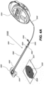
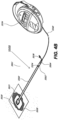
- FIGS. 4A-6 illustrate embodiments of a negative pressure wound treatment system 5501 similar to the embodiment illustrated in FIG. 1 .
- the system 5501 may comprise a flexible suction adapter 5500 having a bridge portion 5502 with a proximal end 5503 and a distal end 5505, and an applicator 5520 at the distal end 5505 of the bridge portion 5502 forming the flexible suction adapter 5500.
- a connector 5504 is preferably disposed at the proximal end 5503 of the bridge portion 5502, so as to connect to at least one of the channels 5512 and/or 5516, as shown in FIG. 4B .
- a cap 5536 may be provided with the system 5501 (and can in some cases, as illustrated, be attached to the connector 5504).
- the cap 5536 can be useful in preventing fluids from leaking out of the proximal end 5503.
- the system 5501 may include a source of negative pressure such as a pump or negative pressure unit 5534 capable of supplying negative pressure.
- the pump also preferably comprises a canister or other container for the storage of wound exudates and other fluids that may be removed from the wound.
- this pump 5534 may be the pump 200 described in relation to FIG. 2 .
- this pump 5534 can be a RENASYS GO pump, as sold by Smith & Nephew.
- the pump 5534 may be connected to the connector 5504 via a tube 5540.
- the applicator 5520 is placed over an aperture 5535 formed in a drape 5531 that is placed over a suitably-prepared wound 5530, which may in some cases be filled with a wound packing material such as foam or gauze. Subsequently, with the pump 5534 connected via the tube 5540 to the connector 5504, the pump is activated, thereby supplying negative pressure to the wound. Application of negative pressure may be applied until a desired level of healing of the wound 5530 is achieved.
- the bridge portion 5502 may comprise an upper channel layer 5512 positioned between an upper layer 5510 and an intermediate layer 5514, with a lower channel layer 5516 positioned between the intermediate layer 5514 and a bottom layer 5518.
- the layers 5510, 5514, and 5518 have elongate portions extending between proximal and distal ends and may be comprised of a material that is fluid-impermeable, for example polymers such as polyurethane. It will of course be appreciated that the layers 5510, 5514, and 5518 may each be constructed from different materials, including semi-permeable materials. In some embodiments, one or more of the layers 5510, 5514, and 5518 may be at least partially transparent. As illustrated in FIG.
- the upper and lower layers 5510 and 5518 may be curved, rounded or outwardly convex over a majority of their lengths.
- the layers 5510, 5514, and 5518 may be pinched together to weld or adhere the layers together.
- the proximal ends of the channels 5512 and 5516 may be sandwiched between these layers, thus partially compressing the proximal ends of the channels 5512, 5516 and stretching the layers 5510, 5514, 5518 over these aforementioned proximal ends.
- the proximal ends of the materials used in the bridge portion 5502 may not necessarily be rounded or curved; as shown in FIG. 6 , they can remain substantially squared off and straight.
- the upper and lower channel layers 5512 and 5516 are preferably elongate layers extending from the proximal end 5503 to the distal end 5505 and may each preferably comprise a porous material, including for example open-celled foams such as polyethylene or polyurethane.
- one or more of the upper and lower channel layers 5512 and 5516 may be comprised of a fabric, for example a knitted or woven spacer fabric (such as a knitted polyester 3D fabric, Baltex 7970.RTM., or Gehring 879.RTM.) or a nonwoven material. Suitable materials may also include terry-woven or loop-pile materials.
- the fibers may not necessarily be woven, and can include felted and flocked (including materials such as Flotex.RTM.) fibrous materials.
- the materials selected are preferably suited to channeling wound exudate away from the wound and for transmitting negative pressure and/or vented air to the wound site, and may also confer a degree of kinking or occlusion resistance to the channel layers 5512 and 5516 as described below.
- the upper channel layer 5512 may comprise an open-celled foam such as polyurethane, and the lower channel layer may comprise a fabric as described herein.
- the upper channel layer is optional, and the system may instead be provided with an open upper channel. In the embodiment illustrated in FIG.
- the upper channel layer 5512 may have a curved, rounded or upwardly convex upper surface and a substantially flat lower surface
- the lower channel layer 5516 may have a curved, rounded or downwardly convex lower surface and a substantially flat upper surface
- the fabric may have a three-dimensional (3D) structure, where one or more types of fibers form a structure where the fibers extend in all three dimensions.
- 3D three-dimensional
- Such a fabric may in some cases aid in wicking, transporting fluid, and/or transmitting negative pressure.
- To prevent the channels 5512 and/or 5516 from being displaced or twisted while encased in the system 5501--which may impair performance of the respective channels under negative pressure--it may in some embodiments be preferable to adhere or otherwise secure the channels 5512 and/or 5516 to one or more of the layers 5510, 5514, and 5518.
- these materials remain open and capable of communicating negative pressure to a wound area under the typical pressures used in negative pressure therapy, for example between 40 to 150 mmHg, although higher and lower values are possible.
- the fabric may comprise several layers of material stacked or layered over each other, which may in some cases be useful in preventing the channel 5516 from collapsing under the application of negative pressure.
- the fabric used in channel 5516 may be between 1.5 mm and 6 mm; more preferably, the fabric may be between 3 mm and 6 mm thick, and may be comprised of either one or several individual layers of fabric.
- the channel 5512 may be between 1.2-3 mm thick, and preferably thicker than 1.5 mm.
- the materials used in the system 5501 are preferably conformable and soft, which may help to avoid pressure ulcers and other complications which may result from a wound treatment system being pressed against the skin of a patient. Further examples of 3D fabrics are discussed below in FIGS. 7A-C .
- the distal ends of the layers 5510, 5514, and 5518 and the channel layers 5512 and 5516 are enlarged at their distal ends (to be placed over a wound site), and may form a "teardrop" or other enlarged shape.
- the distal ends of at least the layers 5512, 5514, 5516, and 5518 may also be provided with at least one through aperture. This aperture may be useful not only for the drainage of wound exudate and for applying negative pressure to the wound, but also during manufacturing of the device, as these apertures may be used to align these respective layers appropriately.
- a channel connector 5506 is provided at the proximal end 5503 of the bridge portion 5502, the channel connector 5506 preferably being configured so as to be embedded into the lower channel layer 5516 so as to create a secure fluidic connection.
- the channel connector 5506 may in some embodiments be inserted into a pre-made cavity formed into the channel 5516; as illustrated in FIG. 6 , this cavity can be cut out or can be in the form of a rabbet joint.
- the channel connector 5506 may be one of the connectors described in FIGS. 8A-B below.
- the other end of the channel connector 5506 may be connected or in communication with, in one embodiment, a connector tube 5507, although in some embodiments the channel connector 5506 may be connected directly to the connector 5504, or else connected directly to a tube 5540 connected to a source of negative pressure.
- a connector tube 5507 the resulting assembly can permit a connector 5504 to be attached thereto.
- a cap 5536 which may be secured to the suction adapter for example via a cap leash 5527 secured with a ring disposed on the outer surface of the connector tube 5507.
- the cap 5536 may be used to cover the end of the suction adapter, for example at the connector 5504, so as to prevent exudate and other wound fluids from leaking out.
- the connector 5504 is preferably configured to connect with a tube 5540 connected to a source of negative pressure.
- the connector 5504 may for example comprise a lip or other such structure to aid in securing the connector 5504 to a tube 5540 and/or cap 5536, although it will be understood that other connector types are possible, including quick-disconnect couplings, luer locks, Christmas-tree, and other such connectors.
- the upper layer 5510 may comprise additional material extending downward, preferably at least of the thickness of the bridge portion 5502; this material may then be used to bond or weld to the other layers so to form a fluid-tight seal. More specifically, during assembly, the upper layer 5510 may be attached, for example by melting, welding, or with adhesives, to the lower layer 5518 so as to form a fluid-tight seal (with the exception of the apertures at the distal and proximal ends). Preferably, the middle layer 5514 is attached to the top layer 5510 and the bottom layer 5518.
- the connectors 5504 and/or 5506, as well as the tube 5507 may be preferable to attach or bond to at least one of the layers 5510, 5514, 5518 so as to create a fluid-tight connection.
- some embodiments may also be provided with a weld 5532 made onto the lower layer 5518.
- the lower channel 5516 may have a hole or aperture made through it, which may be used to weld it, via the weld 5532, to the lower layer 5518. This welding of the lower channel 5516 to the lower layer 5518 via the weld 5532 made through the hole 5533 may thus aid in preventing the various layers and channels from shifting or being displaced.
- other securement means may be used, for example adhesives and the like, and that such arrangements may be also be used in the upper channel 5512.
- a controlled air leak 5524 may be disposed on the bridge portion 5502, for example at the proximal end thereof.
- This air leak 5524 may comprise an opening or channel extending through upper layer 5510, such that the air leak 5524 is in fluidic communication with the upper channel 5512.
- the air leak 5524 preferably comprises a filter 5525.
- the air leak 5524 is located at the proximal end of the bridge portion 5502 so as to minimize the likelihood of wound exudate or other fluids coming into contact and possibly occluding or interfering with the air leak 5524 or its filter 5525.
- this filter 5525 is a microporous membrane capable of excluding microorganisms and bacteria, and which may be able to filter out particles larger than 45 ⁇ m.
- the filter 5525 can exclude particles larger than 1.0 ⁇ m, and more preferably, particles larger than 0.2 ⁇ m.
- some embodiments may provide for a filter 5525 that is at least partially chemically-resistant, for example to water, common household liquids such as shampoos, and other surfactants.
- reapplication of vacuum to the suction adapter 5500 and/or wiping of the exposed outer portion of the filter 5525 may be sufficient to clear any foreign substance occluding the filter 5525.
- the filter 5525 may be composed of a suitably-resistant polymer such as acrylic, polyethersulfone, or polytetrafluoroethylene, and may be oleophobic and/or hydrophobic.
- the filter 5525 may also comprise a supporting backing layer, for example a nonwoven polyester support.
- the air leak 5524 will supply a relatively constant air flow that does not appreciably increase as additional negative pressure is applied to the system 5501. In embodiments of the suction adapter 5500 where the air flow through the air leak 5524 increases as additional negative pressure is applied, preferably this increased air flow will be minimized and not increase in proportion to the negative pressure applied thereto.
- the filter 5525 provided in the controlled air leak 5524 in certain embodiments may be useful in a system 5501 for use with more ambulatory and active patients.
- a chemically-resistant filter may permit a patient to bathe or shower without damaging the filter's functionality when reconnected to a source of negative pressure. Any occlusion or fluid blocking the air leak 5524 could then be cleared by, for example, wiping off the filter 5525 or re-applying negative pressure to the suction adapter 5500.
- Such a system would also have the advantage that the system 5501 and any assorted wound dressing materials, if present, would not need to be removed and then re-applied should a patient need to be disconnected from the source of negative pressure, for example incidental to bathing. This would entail significant advantages in improving the cost-effectiveness and ease of use of the present treatment system.
- the suction adapter 5500 is preferably constructed so as to provide a consistent fluid flow even if the suction adapter 5500 is kinked or weighted down.
- the bridge portion 5502 may become folded over itself, or else the patient may roll over, thus placing his or her weight over at least a portion of the suction adapter 5500.
- prior art dressings and fluidic connectors become blocked or ineffective in such situations and in some cases may contribute to complications such as pressure ulcers.
- certain embodiments provide for improved blockage resistance if kinked or weighed down.
- the suction adapter 5500 is able to maintain a flow rate through the air leak 5524 of at least 0.08 L/min, and preferably 0.12 L/min while negative pressure is applied through a source of negative pressure.
- Further embodiments also provide for the suction adapter 5500 to be able to handle fluid exudate drainage from the wound site through the lower channel 5516 of at least 10 L/day, or 6.9 ml/min.
- Certain embodiments provide for the suction adapter 5500 to maintain these flow rates with a weight, for example a 12 kg weight, pressing down on the bridge portion through a rod with a 1 in. diameter.
- these flow rates are also maintained while the bridge portion 5502 is kinked over itself with the same weight, or for example with a 4.75 kg weight placed directly on the folded region. It is preferable that the suction adapter 5500 be able to withstand being folded or kinked over even during an extended period of time, for example over 40 hours, and not show any degradation in performance (e.g., flow rates) compared to its performance prior to being folded or kinked over. Preferably, embodiments of the suction adapter 5500 are also able to transmit and maintain a negative pressure at the wound that is close to the negative pressure level at the source of negative pressure.
- an acceptable level of pressure maintained at the wound may be within +-.25 mmHg of the negative pressure set at the source of negative pressure, with this pressure being preferably maintained at this level within 95% of the time that the suction adapter 5500 has negative pressure applied to it.
- Acceptable pressure levels may include pressure ranges between 40-120 mmHg, although levels of 200 mmHg have successfully been used.
- the suction adapter 5500 also comprises an applicator 5520 designed for placement over a wound site.
- the applicator 5520 comprises a flexible layer 5550, for example polyethylene or polyurethane, with a layer of adhesive on its lower (wound-facing) side.
- a protective release layer 5529 may be placed on the adhesive layer, which is removable before use.
- a more rigid removable backing layer 5552 may be provided on the upper side of the applicator 5520 to facilitate handling of the applicator 5520 due to the flexibility of the layer 5550.
- the applicator 5520 preferably comprises an attachment point for the bridge 5502 at the distal end 5505, for example using a section of double-sided adhesive tape 5528.
- the double-sided adhesive tape 5528 may be protected by an additional protective release layer, which is removed prior to adhering the bridge 5502 to the applicator 5520.
- attachment methods are also contemplated, for example heat sealing, welding, or suitable adhesives. Some embodiments may also permit the manufacture of the bridge 5502 and the applicator 5520 as a single unit that does not require separate attachment means.
- the applicator 5520 preferably comprises at least one aperture 5526 through itself and designed to be placed over a wound site, and which can serve to fluidically connect the wound site to the source of negative pressure and to the air leak while also serving as a conduit to draw out wound exudate from the wound site.
- the system 5501 may be used in a similar fashion to the other embodiments previously disclosed herein, such as the system 100 described in relation to FIG. 1 .
- a wound site 5530 is preferably cleaned and prepared in a suitable fashion, and a wound packing material, if necessary, placed into the wound site, followed by a drape 5531.
- An aperture 5535 through the drape to the wound site is then created, although some embodiments may have a pre-made aperture 5535. Subsequently, an operator may situate the applicator portion 5520 over the aperture 5535.
- a fluidic conduit such as a tube 5540 may then be connected to the connector 5504.
- the tube 5540 may also be connected to connector 5504 prior to applying the applicator to the wound site.
- the fluidic conduit is connected to a source of negative pressure 5534, preferably with a container suitable for containing wound exudate interposed therebetween. The application of negative pressure may then be effectuated to the wound site 5530 until the wound site progresses to a desired level of healing.
- wound exudate from the wound site 5530 is drawn by the negative pressure through the lower channel layer 5516.
- the air leak 5524 allows air to pass through the upper channel layer 5512 into the apertures through the distal ends of the layers 5512, 5514, 5516 and 5518.
- the negative pressure draws air passing through the upper channel layer into the lower channel layer 5516 back toward the source of negative pressure or pump.
- the controlled air leak 5524 provides a constant flow of air through the suction adapter 5500, which then may be used to determine whether blockage or leakage is present.
- causes of blockage can include, for example, situations where the lower channel 5516 becomes occluded with wound debris.
- Leakage causes can include, for example, improper sealing of the drape over the wound site, or physical damage to the suction adapter 5500 leading to excess air leaking into the system.
- the blockage or leakage may be determined, in certain embodiments, by measuring the speed of the pump while the pump works to maintain a constant negative pressure. Pump speed may also be measured indirectly by measuring the amount of voltage or signal sent to the pump.
- Figure 7A illustrates an embodiment of a negative pressure wound treatment system 70 employing a wound dressing 700 in conjunction with a fluidic connector 710. Additional examples related to negative pressure wound treatment comprising a wound dressing in combination with a pump as described herein may also be used in combination or in addition to those described in US Patent No. 9,061,095 , which is incorporated by reference in its entirety.
- the fluidic connector 710 may comprise an elongate conduit, more preferably a bridge 720 having a proximal end 730 and a distal end 740, and an applicator 780 at the distal end 740 of the bridge 720.
- the system 70 may include a source of negative pressure such as a pump or negative pressure unit 750 capable of supplying negative pressure.
- the pump may comprise a canister or other container for the storage of wound exudates and other fluids that may be removed from the wound.
- a canister or container may also be provided separate from the pump.
- the pump 750 can be a canisterless pump such as the PICO TM pump, as sold by Smith & Nephew.
- the pump 750 may be connected to the bridge 720 via a tube, or the pump 750 may be connected directly to the bridge 720.
- the dressing 700 is placed over a suitably-prepared wound, which may in some cases be filled with a wound packing material such as foam or gauze as described above.
- the applicator 780 of the fluidic connector 710 has a sealing surface that is placed over an aperture in the dressing 700 and is sealed to the top surface of the dressing 700.
- the pump 750 is connected via the tube to the coupling 760, or is connected directly to the bridge 720. The pump is then activated, thereby supplying negative pressure to the wound. Application of negative pressure may be applied until a desired level of healing of the wound is achieved.
- the fluidic connector 710 preferably comprises an enlarged distal end, or head 740 that is in fluidic communication with the dressing 700 as will be described in further detail below.
- the enlarged distal end has a round or circular shape.
- the head 740 is illustrated here as being positioned near an edge of the dressing 700, but may also be positioned at any location on the dressing. For example, some embodiments may provide for a centrally or off-centered location not on or near an edge or corner of the dressing 700.
- the dressing 70 may comprise two or more fluidic connectors 710, each comprising one or more heads 740, in fluidic communication therewith.
- the head 740 may measure 30mm along its widest edge.
- the head 740 forms at least in part the applicator 780, described above, that is configured to seal against a top surface of the wound dressing.
- Figure 7C illustrates a cross-section through a wound dressing 700 similar to the wound dressing 70 as described in International Patent Publication WO2013175306 A2 , which is incorporated by reference in its entirety, along with fluidic connector 710.
- the wound dressing 700 which can alternatively be any wound dressing embodiment disclosed herein or any combination of features of any number of wound dressing embodiments disclosed herein, can be located over a wound site to be treated.
- the dressing 700 may be placed as to form a sealed cavity over the wound site.
- the dressing 700 comprises a top or cover layer, or backing layer 820 attached to an optional wound contact layer 822, both of which are described in greater detail below. These two layers 820, 822 are preferably joined or sealed together so as to define an interior space or chamber.
- This interior space or chamber may comprise additional structures that may be adapted to distribute or transmit negative pressure, store wound exudate and other fluids removed from the wound, and other functions which will be explained in greater detail below.
- additional structures that may be adapted to distribute or transmit negative pressure, store wound exudate and other fluids removed from the wound, and other functions which will be explained in greater detail below. Examples of such structures, described below, include a transmission layer 826 and an absorbent layer 821.
- the upper layer, top layer, or layer above refers to a layer furthest from the surface of the skin or wound while the dressing is in use and positioned over the wound.
- the lower surface, lower layer, bottom layer, or layer below refers to the layer that is closest to the surface of the skin or wound while the dressing is in use and positioned over the wound.
- the wound contact layer 822 can be a polyurethane layer or polyethylene layer or other flexible layer which is perforated, for example via a hot pin process, laser ablation process, ultrasound process or in some other way or otherwise made permeable to liquid and gas.
- the wound contact layer 822 has a lower surface 824 and an upper surface 823.
- the perforations 825 preferably comprise through holes in the wound contact layer 822 which enable fluid to flow through the layer 822.
- the wound contact layer 822 helps prevent tissue ingrowth into the other material of the wound dressing.
- the perforations are small enough to meet this requirement while still allowing fluid to flow therethrough.
- perforations formed as slits or holes having a size ranging from 0.025 mm to 1.2 mm are considered small enough to help prevent tissue ingrowth into the wound dressing while allowing wound exudate to flow into the dressing.
- the wound contact layer 822 may help maintain the integrity of the entire dressing 700 while also creating an air tight seal around the absorbent pad in order to maintain negative pressure at the wound.
- the wound contact layer 822 may also act as a carrier for an optional lower and upper adhesive layer (not shown).
- a lower pressure sensitive adhesive may be provided on the lower surface 824 of the wound dressing 700 whilst an upper pressure sensitive adhesive layer may be provided on the upper surface 823 of the wound contact layer.
- the pressure sensitive adhesive which may be a silicone, hot melt, hydrocolloid or acrylic based adhesive or other such adhesives, may be formed on both sides or optionally on a selected one or none of the sides of the wound contact layer. When a lower pressure sensitive adhesive layer is utilized may be helpful to adhere the wound dressing 700 to the skin around a wound site.
- the wound contact layer may comprise perforated polyurethane film.
- the lower surface of the film may be provided with a silicone pressure sensitive adhesive and the upper surface may be provided with an acrylic pressure sensitive adhesive, which may help the dressing maintain its integrity.
- a polyurethane film layer may be provided with an adhesive layer on both its upper surface and lower surface, and all three layers may be perforated together.
- a transmission layer 826 can be located above the wound contact layer 822.
- the transmission layer can be a porous material.
- the transmission layer can be referred to as a spacer layer and the terms can be used interchangeably to refer to the same component described herein.
- This transmission layer 726 allows transmission of fluid including liquid and gas away from a wound site into upper layers of the wound dressing.
- the transmission layer 826 preferably ensures that an open-air channel can be maintained to communicate negative pressure over the wound area even when the absorbent layer has absorbed substantial amounts of exudates.
- the layer 826 should preferably remain open under the typical pressures that will be applied during negative pressure wound therapy as described above, so that the whole wound site sees an equalized negative pressure.
- the layer 826 may be formed of a material having a three-dimensional structure.
- a knitted or woven spacer fabric for example Baltex 7970 weft knitted polyester
- a non-woven fabric could be used.
- the three-dimensional material can comprise a 3D spacer fabric material similar to the material described in International Publication WO 2013/175306 A2 and International Publication WO2014/020440 , the disclosures of which are incorporated by reference in their entireties.
- the wound dressing 700 may incorporate or comprise a multi-care WCL as described herein this section or elsewhere in the specification.
- the wound dressing 700 may incorporate any of the multi-care WCLs disclosed herein this section or elsewhere in the specification.
- the multi-care WCL may be incorporated as a whole component layer or a part of a component layer.
- the multi-care WCL layer may be provided below the transmission layer 826.
- the multi-care WCL layer may be provided above the wound contact layer 822.
- the multi-care WCL layer may replace the transmission layer 826, such that the multi-care WCL layer is provided between an absorbent layer 221 (described further below) and the wound contact layer 822.
- the multi-care WCL layer can supplement or replace the absorbent layer 821.
- the wound dressing 700 does not have the wound contact layer 822, and the multi-care WCL layer may be the lowermost layer of the wound dressing 700.
- the multi-care WCL may have same or substantially similar size and shape with the transmission layer 826 and/or the absorbent layer 821.
- the multi-care WCL layer may be constructed to be flexible but stiff enough to withstand negative pressure, such that the multi-care WCL is not collapsed excessively and thereby transmits negative pressure sufficiently to the wound when negative pressure is supplied to the wound dressing 700.
- the multi-care WCL layer may be constructed to include sufficient number or size of pores to enable transmission of negative pressure through it.
- the multi-care WCL layer may have suitable thickness to transmit enough negative pressure to the wound.
- the multi-care WCL layer may have a thickness of 1 mm to 10 mm, or 1 mm to 7 mm, or 1.5 mm to 7 mm, or 1.5 mm to 4 mm, or 2 mm to 3 mm. In some embodiments, the multi-care WCL may have a thickness of approximately 2 mm.
- the layer 821 of absorbent material is provided above the transmission layer 826.
- the absorbent material which can comprise a foam or non-woven natural or synthetic material, and which may optionally comprise a super-absorbent material, forms a reservoir for fluid, particularly liquid, removed from the wound site.
- the layer 821 may also aid in drawing fluids towards the backing layer 220.
- the material of the absorbent layer 821 may also prevent liquid collected in the wound dressing 700 from flowing freely within the dressing, and preferably acts so as to contain any liquid collected within the dressing.
- the absorbent layer 821 also helps distribute fluid throughout the layer via a wicking action so that fluid is drawn from the wound site and stored throughout the absorbent layer. This helps prevent agglomeration in areas of the absorbent layer.
- the capacity of the absorbent material must be sufficient to manage the exudates flow rate of a wound when negative pressure is applied. Since in use the absorbent layer experiences negative pressures the material of the absorbent layer is chosen to absorb liquid under such circumstances. A number of materials exist that are able to absorb liquid when under negative pressure, for example superabsorber material.
- the absorbent layer 821 may typically be manufactured from ALLEVYN TM foam, Freudenberg 114-224-4 or Chem-Posite TM 11C-450.
- the absorbent layer 821 may comprise a composite comprising superabsorbent powder, fibrous material such as cellulose, and bonding fibers.
- the composite is an air-laid, thermally-bonded composite.
- the absorbent layer 821 is a layer of non-woven cellulose fibers having super-absorbent material in the form of dry particles dispersed throughout.
- Use of the cellulose fibers introduces fast wicking elements which help quickly and evenly distribute liquid taken up by the dressing.
- the juxtaposition of multiple strand-like fibers leads to strong capillary action in the fibrous pad which helps distribute liquid.
- the super-absorbent material is efficiently supplied with liquid.
- the wicking action also assists in bringing liquid into contact with the upper cover layer to aid increase transpiration rates of the dressing.
- An aperture, hole, or orifice 827 is preferably provided in the backing layer 820 to allow a negative pressure to be applied to the dressing 700.
- the fluidic connector 710 is preferably attached or sealed to the top of the backing layer 820 over the orifice 827 made into the dressing 700, and communicates negative pressure through the orifice 827.
- a length of tubing may be coupled at a first end to the fluidic connector 710 and at a second end to a pump unit (not shown) to allow fluids to be pumped out of the dressing.
- a length of tubing may be coupled at a first end of the fluidic connector such that the tubing, or conduit, extends away from the fluidic connector parallel or substantially to the top surface of the dressing.
- the fluidic connector 710 may be adhered and sealed to the backing layer 820 using an adhesive such as an acrylic, cyanoacrylate, epoxy, UV curable or hot melt adhesive.
- the fluidic connector 710 may be formed from a soft polymer, for example a polyethylene, a polyvinyl chloride, a silicone or polyurethane having a hardness of 30 to 90 on the Shore A scale. In some embodiments, the fluidic connector 710 may be made from a soft or conformable material.
- the absorbent layer 821 includes at least one through hole 828 located so as to underlie the fluidic connector 710.
- the through hole 828 may in some embodiments be the same size as the opening 827 in the backing layer, or may be bigger or smaller.
- a single through hole can be used to produce an opening underlying the fluidic connector 710. It will be appreciated that multiple openings could alternatively be utilized.
- one or multiple openings may be made in the absorbent layer in registration with each respective fluidic connector.
- the use of through holes in the super-absorbent layer may provide a fluid flow pathway which remains unblocked in particular when the absorbent layer is near saturation.
- the aperture or through-hole 828 is preferably provided in the absorbent layer 821 beneath the orifice 827 such that the orifice is connected directly to the transmission layer 826 as illustrated in Figure 2C. This allows the negative pressure applied to the fluidic connector 710 to be communicated to the transmission layer 826 without passing through the absorbent layer 821. This ensures that the negative pressure applied to the wound site is not inhibited by the absorbent layer as it absorbs wound exudates. In other embodiments, no aperture may be provided in the absorbent layer 821, or alternatively a plurality of apertures underlying the orifice 827 may be provided.
- additional layers such as another transmission layer or an obscuring layer such as described with reference to Figures 6A-6B and in International Patent Publication WO2014/020440 , the entirety of which is hereby incorporated by reference, may be provided over the absorbent layer 821 and beneath the backing layer 820.
- the backing layer 820 is preferably gas impermeable, but moisture vapor permeable, and can extend across the width of the wound dressing 700.
- the backing layer 820 which may for example be a polyurethane film (for example, Elastollan SP9109) having a pressure sensitive adhesive on one side, is impermeable to gas and this layer thus operates to cover the wound and to seal a wound cavity over which the wound dressing is placed. In this way, an effective chamber is made between the backing layer 820 and a wound site where a negative pressure can be established.
- the backing layer 820 is preferably sealed to the wound contact layer 822 in a border region around the circumference of the dressing, ensuring that no air is drawn in through the border area, for example via adhesive or welding techniques.
- the backing layer 820 protects the wound from external bacterial contamination (bacterial barrier) and allows liquid from wound exudates to be transferred through the layer and evaporated from the film outer surface.
- the backing layer 820 preferably comprises two layers; a polyurethane film and an adhesive pattern spread onto the film.
- the polyurethane film is preferably moisture vapor permeable and may be manufactured from a material that has an increased water transmission rate when wet.
- the moisture vapor permeability of the backing layer increases when the backing layer becomes wet.
- the moisture vapor permeability of the wet backing layer may be up to about ten times more than the moisture vapor permeability of the dry backing layer.
- the absorbent layer 821 may be of a greater area than the transmission layer 826, such that the absorbent layer overlaps the edges of the transmission layer 826, thereby ensuring that the transmission layer does not contact the backing layer 820.
- This provides an outer channel of the absorbent layer 821 that is in direct contact with the wound contact layer 822, which aids more rapid absorption of exudates to the absorbent layer. Furthermore, this outer channel ensures that no liquid is able to pool around the circumference of the wound cavity, which may otherwise seep through the seal around the perimeter of the dressing leading to the formation of leaks.
- the absorbent layer 821 may define a smaller perimeter than that of the backing layer 820, such that a boundary or border region is defined between the edge of the absorbent layer 821 and the edge of the backing layer 820.
- one embodiment of the wound dressing 700 comprises an aperture 828 in the absorbent layer 821 situated underneath the fluidic connector 710.
- a wound facing portion of the fluidic connector may thus come into contact with the transmission layer 826, which can thus aid in transmitting negative pressure to the wound site even when the absorbent layer 821 is filled with wound fluids.
- Some embodiments may have the backing layer 820 be at least partly adhered to the transmission layer 826.
- the aperture 828 is at least 1-2 mm larger than the diameter of the wound facing portion of the fluidic connector 710, or the orifice 827.
- the fluidic connector 710 and through hole may be located in an off-center position as illustrated in Figure 7B .
- Such a location may permit the dressing 700 to be positioned onto a patient such that the fluidic connector 710 is raised in relation to the remainder of the dressing 700. So positioned, the fluidic connector 710 and the filter 814 may be less likely to come into contact with wound fluids that could prematurely occlude the filter 814 so as to impair the transmission of negative pressure to the wound site.
- some wound dressings comprise a perforated wound contact layer with silicone adhesive on the skin-contact face and acrylic adhesive on the reverse.
- the wound contact layer may be constructed from polyurethane, polyethylene or polyester.
- a transmission layer Above this bordered layer sits a transmission layer.
- an absorbent layer Above the transmission layer, sits an absorbent layer.
- the absorbent layer can include a superabsorbent non-woven (NW) pad.
- NW superabsorbent non-woven
- the absorbent layer can over-border the transmission layer by approximately 5mm at the perimeter.
- the absorbent layer can have an aperture or through-hole toward one end. The aperture can be about 10 mm in diameter.
- a backing layer Over the transmission layer and absorbent layer lies a backing layer.
- the backing layer can be a high moisture vapor transmission rate (MVTR) film, pattern coated with acrylic adhesive.
- MVTR moisture vapor transmission rate
- the high MVTR film and wound contact layer encapsulate the transmission layer and absorbent layer, creating a perimeter border of approximately 20 mm.
- the backing layer can have a 10 mm aperture that overlies the aperture in the absorbent layer.
- Above the hole can be bonded a fluidic connector that comprises a liquid-impermeable, gas-permeable semi-permeable membrane (SPM) or filter that overlies the aforementioned apertures.
- SPM liquid-impermeable, gas-permeable semi-permeable membrane
- a source of negative pressure (such as a pump) and some or all other components of the TNP system, such as power source(s), sensor(s), connector(s), user interface component(s) (such as button(s), switch(es), speaker(s), screen(s), etc.) and the like, can be integral with the wound dressing.
- some embodiments related to wound treatment comprising a wound dressing described herein may also be used in combination or in addition to those described in International Application WO 2016/174048 and International Patent Application PCT/EP2017/055225, filed on March 6, 2017 , entitled "WOUND TREATMENT APPARATUSES AND METHODS WITH NEGATIVE PRESSURE SOURCE INTEGRATED INTO THE WOUND DRESSING," including further details relating to embodiments of wound dressings, the wound dressing components and principles, and the materials used for the wound dressings and wound dressing components.
- the pump and/or other electronic components can be configured to be positioned adjacent to or next to the absorbent and/or transmission layers in the wound dressing so that the pump and/or other electronic components are still part of a single apparatus to be applied to a patient with the pump and/or other electronics positioned away from the wound site.
- Figure 8A illustrates a wound dressing incorporating the source of negative pressure and/or other electronic components within the wound dressing.
- Figure 8A illustrates a wound dressing 1200 with the pump and/or other electronics positioned away from the wound site.
- the wound dressing can include an electronics area 1261 and an absorbent area 1260.
- the dressing can comprise a wound contact layer (not shown) and a moisture vapor permeable film or cover layer 1213 positioned above the contact layer and other layers of the dressing.
- the wound dressing layers and components of the electronics area as well as the absorbent area can be covered by one continuous cover layer 1213 as shown in Figure 8A .
- the electronics area 1261 can include a source of negative pressure (such as a pump) and some or all other components of the TNP system, such as power source(s), sensor(s), connector(s), user interface component(s) (such as button(s), switch(es), speaker(s), screen(s), etc.) and the like, that can be integral with the wound dressing.
- a source of negative pressure such as a pump
- the electronics area 1261 can include a button or switch 1211 as shown in Figure 8A .
- the button or switch 1211 can be used for operating the pump (e.g., turning the pump on/off).
- the absorbent area 1260 can include an absorbent material 1212 and can be positioned over the wound site.
- the electronics area 1261 can be positioned away from the wound site, such as by being located off to the side from the absorbent area 1260.
- the electronics area 1261 can be positioned adjacent to and in fluid communication with the absorbent area 1260 as shown in Figure 8A .
- each of the electronics area 1261 and absorbent area 1260 may be rectangular in shape and positioned adjacent to one another.
- additional layers of dressing material can be included in the electronics area 1261, the absorbent area 1260, or both areas.
- the dressing can comprise one or more spacer or transmission layers and/or one or more absorbent layers positioned above the contact layer and below the wound cover layer 1213 of the dressing.
- the dressing can comprise a multi-care WCL, as described above or described elsewhere herein, a transmission layer (not shown), an absorbent layer 1212 over the transmission layer, a moisture vapor permeable film or cover layer 1213 positioned above the wound contact layer, transmission layer, absorbent layer, or other layers of the dressing.
- the wound contact layer can be configured to be in contact with the wound.
- the wound contact layer can include an adhesive on the patient facing side for securing the dressing to the surrounding skin or on the top side for securing the wound contact layer to a cover layer or other layer of the dressing.
- the wound contact layer can be configured to provide unidirectional flow so as to facilitate removal of exudate from the wound while blocking or substantially preventing exudate from returning to the wound.
- the one or more transmission layers assist in distributing negative pressure over the wound site and facilitating transport of wound exudate and fluids into the wound dressing.
- the transmission layer can be formed at least partially from a three-dimensional (3D) fabric.
- an absorbent layer (such as layer 1212) for absorbing and retaining exudate aspirated from the wound can be utilized.
- a superabsorbent material can be used in the absorbent layer 1212.
- the absorbent includes a shaped form of a superabsorber layer.
- the wound dressing layers of the electronics area and the absorbent layer can be covered by one continuous cover layer 1213.
- the cover layer can include a moisture vapor permeable material that prevents liquid exudate removed from the wound and other liquids from passing through, while allowing gases through.
- Figure 8B illustrates an embodiment of layers of a wound dressing with the pump and electronic components offset from the absorbent area of the dressing.
- the dressing can include a wound contact layer 1310 for placing in contact with the wound.
- Lower spacer or transmission layers 1311 and 1311' are provided above the wound contact layer 1310.
- the transmission layer 1311 can be a separate layer from spacer layer 1311' as shown in Figure 8B .
- the lower transmission layers 1311 and/or 1311' can assist in distributing pressure evenly to the wound surface and/or wicking fluid away from the wound.
- An absorbent layer 1322 can be positioned above the lower transmission layer 1311.
- a dressing layer 1351 can include cutouts or recesses 1328 for embedding the electronic components 1350 within the layer 1351.
- the cutouts or recesses 1328 can be sized and shaped to embed a pump 1327, power source 1326, and/or other electronic components.
- the layer 1351 can include multiple spacer or transmission layers stacked together. In some embodiments, the layer 1351 can include multiple spacer or transmission layers pieced together to surround the electronic components 1350.
- An upper transmission layer 1317 can be provided above the absorbent layer 1322, layer 1351, and/or electronic components 1350.
- the wound dressing 1200, 1300 may incorporate or comprise a multi-care WCL as described herein this section or elsewhere in the specification.
- the wound dressing 1200, 1300 may incorporate any of the multi-care WCLs disclosed herein this section or elsewhere in the specification.
- the multi-care WCL layer may be provided below the transmission layer 1311.
- the multi-care WCL layer may be provided below the wound contact layer 1310.
- the multi-care WCL layer may replace the transmission layer 1311, 1311' such that the multi-care WCL layer is provided between an absorbent layer 1322 and the wound contact layer 1310.
- the multi-care WCL layer can supplement or replace the absorbent layer 1212, 1322.
- the multi-care WCL layer may be the lowermost layer of the wound dressing.
- the multi-care WCL layer may have same or substantially similar size and shape with the transmission layers and/or the absorbent layers described herein this section or elsewhere in the specification.
- the multi-care WCL layer may be constructed to be flexible but stiff enough to withstand negative pressure, such that the multi-care WCL layer is not collapsed excessively and thereby transmits negative pressure sufficiently to the wound when negative pressure is supplied to the wound dressing 1200.
- the multi-care WCL layer may be constructed to include sufficient number or size of pores to enable transmission of negative pressure through it. Further, the multi-care WCL layer may have suitable thickness to transmit enough negative pressure to the wound.
- the multi-care WCL layer may have a thickness of 1 mm to 10 mm, 1 mm to 7 mm, 1.5 to 7 mm, 1.5 mm to 4 mm, or 2 mm to 3 mm. In some embodiments, the multi-care WCL layer may have a thickness of approximately 2 mm.
- a cover layer or backing layer 1313 can be positioned over the upper transmission layer 1317.
- the backing layer 1313 can form a seal to the wound contact layer 1310 at a perimeter region enclosing the transmission layers 1311, 1311', and 1317, the absorbent layer 1322, layer 1351, and electronic components 1350.
- the backing layer 1313 can be a flexible sheet of material that forms and molds around the dressing components when they are applied to the wound.
- the backing layer 1313 can be a material that is preformed or premolded to fit around the dressing components as shown in Figure 8B .
- components of a reduced pressure wound treatment (NPWT) or TNP system/apparatus such as a wound dressing or a suction adapter may need to be replaced during treatment.
- the wound dressing may be saturated with wound exudate, or a suction adapter may be clogged or damaged.
- different types of TNP systems may need to be used at different stages of the treatment.
- a wound may initially contain and generate larger amounts of exudate, and the treatment may start with a system including a larger pump and a canister for the collection of greater volumes of wound exudate, such as RENASYS-F, RENASYS-G, RENASYS AB sold by Smith & Nephew.
- the patient may be switched to a smaller disposable/portable device such as PICO sold by Smith & Nephew.
- PICO sold by Smith & Nephew.
- Such a change in pump and dressing arrangement may improve the experience for the patient, allowing the patient to avoid an unneeded bulkier dressing and canister combination.
- Wound dressing or drapes covering the wound may need to be removed in these instances when switching pump types, thereby exposing the wound for a certain time.
- different types of TNP systems may use different wound dressings or drapes, or wound dressings or drapes may be damaged when the rest of the TNP system is decoupled from the wound dressings or drapes. Further, the wound may be exposed to infection while uncovered.
- a drape or wound dressing will need to be resilient enough to withstand multiple removal and installation steps of TNP systems while maintaining a seal over/around a wound. Further, a drape or a wound dressing which can accommodate different types of TNP systems without being removed from the wound may be needed.
- FIG. 9 illustrates an exploded view of a drape 900 for negative pressure wound therapy (NPWT).
- the drape or cover layer 900 includes a wound contact layer 950, a spacer layer 940, a support layer 930, a cover layer 920 and a reinforcement member 910.
- the drape 900 may include any additional components of wound dressings or drapes described elsewhere herein the specification.
- the wound contact layer 950 is the lowermost layer of the drape 900 and may act as the primary interface between a wound and the drape 900.
- the wound contact layer 950 may be similar to any wound contact layers described elsewhere herein, such as the wound contact layer 822 and the wound contact layer 1310.
- the wound contact layer 950 may be a polyurethane layer or polyethylene layer or other flexible layer which is perforated, for example via a hot pin process, laser ablation process, ultrasound process or in some other way or otherwise made permeable to liquid and gas.
- the perforations preferably comprise through holes in the wound contact layer 950 which enable fluid to flow through the wound contact layer 950.
- the wound contact layer 950 may help preventing tissue ingrowth into the other material of the wound dressing.
- the perforations are small enough to meet this requirement while still allowing fluid to flow therethrough.
- perforations formed as slits or holes having a size ranging from 0.025 mm to 1.2 mm are considered small enough to help prevent tissue ingrowth into the wound dressing while allowing wound exudate to flow into the dressing.
- the wound contact layer 950 may help maintain the integrity of the entire drape 900 while also creating an air tight seal around the wound in order to maintain negative pressure at the wound. In operation, the wound contact layer 950 may provide unidirectional flow so as to facilitate removal of exudate from the wound while blocking or substantially preventing exudate from returning to the wound.
- the wound contact layer 950 can include an adhesive on the patient facing side for securing the dressing to the surrounding skin or on the top side for securing the wound contact layer to a cover layer or other layer of the dressing. Some embodiments of the wound contact layer 950 may also act as a carrier for an optional lower and upper adhesive layer (not shown). For example, a lower pressure sensitive adhesive may be provided on the lower surface of the drape 900 whilst an upper pressure sensitive adhesive layer may be provided on the upper surface of the wound contact layer 950.
- the pressure sensitive adhesive which may be a silicone, hot melt, hydrocolloid or acrylic based adhesive or other such adhesive, may be formed on both sides or optionally on a selected one or none of the sides of the wound contact layer 950.
- the wound contact layer 950 may comprise perforated polyurethane film.
- the lower surface of the film may be provided with a silicone pressure sensitive adhesive and the upper surface may be provided with an acrylic pressure sensitive adhesive, which may help the dressing maintain its integrity.
- a polyurethane film layer may be provided with an adhesive layer on both its upper surface and lower surface, and all three layers may be perforated together.
- the spacer layer 940 is positioned above the wound contact layer 950.
- the spacer layer 940 can assist in distributing negative pressure evenly to the wound surface and/or wicking exudate away from the wound and/or periwound into upper layers of the drape 900.
- the spacer layer 940 may be similar with any spacer layer or transmission layer described elsewhere herein, such as the transmission layer 826.
- the spacer layer 940 can be a porous material.
- the spacer layer 940 preferably ensures that an open-air channel can be maintained to communicate negative pressure over the wound area even when the absorbent layer has absorbed substantial amounts of exudates.
- the spacer layer 940 may remain open under the typical pressures that will be applied during negative pressure wound therapy as described above, such that the whole wound site sees an equalized negative pressure.
- the spacer layer 940 may be formed of a material having a three-dimensional structure.
- a knitted or woven spacer fabric for example Baltex 7970 weft knitted polyester
- a non-woven fabric could be used.
- the three-dimensional material can comprise a 3D spacer fabric material similar to the material described in International Publication WO 2013/175306 A2 and International Publication WO2014/020440 .
- the cover layer 920 may be similar to any cover layers or backing layers described elsewhere herein, such as the cover layer 1213, the cover layer or backing layer 1313 and the backing layer 820.
- the cover layer 920 which may for example be a polyurethane film (for example, Elastollan SP9109) having a pressure sensitive adhesive on one side, is impermeable to gas and this layer thus operates to cover the wound and to seal a wound cavity over which the wound dressing is placed. In this way, an effective chamber can be made between the cover layer 920 and a wound site where a negative pressure can be established.
- the cover layer can include a moisture vapor permeable material that prevents liquid exudate removed from the wound and other liquids from passing through, while allowing gases through.
- the cover layer 920 may be sealed to the wound contact layer 950 in a border region around the circumference of the drape, ensuring that no air is drawn in through the border area, for example via adhesive or welding techniques.
- the cover layer 920 can protect the wound from external bacterial contamination (bacterial barrier) and/or allow liquid from wound exudates to be transferred through the layer and evaporated from the film outer surface.
- the cover layer 920 may comprise two layers; a polyurethane film and an adhesive pattern spread onto the film.
- the polyurethane film may be moisture vapor permeable and may be manufactured from a material that has an increased water transmission rate when wet.
- the moisture vapor permeability of the backing layer increases when the backing layer becomes wet.
- the moisture vapor permeability of the wet cover layer may be up to about ten times more than the moisture vapor permeability of the dry cover layer.
- the cover layer 920 is transparent or translucent.
- the cover layer 920 includes an opening 922 through the thickness of the cover layer 920.
- the opening 922 is fluidically connected with a source of a negative pressure, and deliver negative pressure to the drape 900 and the wound, and wound exudate may be moved from the drape 900 through the opening 922.
- the opening 922 may include one or more openings.
- the opening 922 is formed in a central region of the cover layer 920, but the opening 922 may be positioned at any suitable location in the cover layer 920.
- the opening 922 may be horizontally biased to one side.
- the opening 922 has a square or a substantially square shape, but the opening 922 may have any suitable shapes.
- the opening 922 can have a circular, rectangular, triangular, or oval shape.
- the drape 900 can include layers or components to enhance structural integrity of the drape 900, such that the drape 900 can withstand multiple application and removal of TNP components (e.g. a wound dressing, a suction adapter) to the it.
- the drape 900 includes the support layer 930.
- the support layer 930 may be more rigid than other layers such as the cover layer 920, the spacer layer 940 or the wound contact layer 950, such that the support layer 930 can increase the overall structural strength of the drape 920.
- the support layer 930 may be elastic and can be bent to some degree, such that the drape 900 does not disrupt the wound tissue and conforms to the patient's body.
- the support layer 930 may have a thickness less than about: 1 cm, 7 mm, 5 mm, 4 mm, 3 mm, or 1 mm.
- the support layer 930 may include one or more polymeric materials, such as polyethylene (PE), polyethylene terephthalate (PET), polypropylene (PP), polystyrene (PS), polyvinyl chloride (PVC), or silicone.
- the support layer 930 is completely or substantially transparent.
- the support layer 930 is translucent.
- the support layer 930 includes one or more perforations 932 through the support layer to facilitate wound exudate removal. Each of the one or more perforations 932 may be sized to allow wound exudate flow through it.
- each of the perforations 932 may have a diameter greater than about: 0.1 mm, 0.3 mm, 0.5 mm, 1 mm, 2 mm, or 5 mm.
- the one or more perforations 932 may be distributed across the support layer 930.
- the one or more perforations 932 may be more concentrated at one or more locations, such as a central region, or a region beneath the opening 922.
- the support layer 930 is included between the cover layer 920 and the spacer layer 940.
- the support layer 930 may be positioned anywhere between the cover layer 920 and the wound contact layer 950.
- the support layer 930 may be included between the spacer layer 940 and the wound contact layer 950.
- the support layer 930 can be positioned immediately below the cover layer 920.
- the support layer 930 may be at least partially attached to the wound side surface of the cover layer 920 using adhesive, heat sealing, or any other suitable methods, such that the support layer 930 provides resilience to the cover layer 920.
- the opening 922 expose a portion of the support layer 930 underneath the opening 922.
- the suction adapter when a suction adapter is applied to the drape 900 over the opening 922 of the cover layer 920, at least a portion of the suction adapter can be coupled to the exposed portion of the support layer 920, such that the force exerted by the suction adapter to the cover layer 920 can be reduced.
- the support layer 930 may be smaller than the spacer layer 940.
- the drape 900 may further include a removable or replaceable cover for the opening 922, such that the opening 922 may be sealed when no suction adapter or the wound dressing is attached to the drape 900.
- the reinforcement member 910 is positioned over the cover layer 920.
- the reinforcement member 910 can reinforce the cover layer 920 over the area where a wound dressing or a suction adapter of a TNP system will be applied.
- the reinforcement member 912 may be made of similar material with the cover layer 912.
- the reinforcement member 912 may be made of a polymeric film material.
- the reinforcement member 912 may be made of a stiffer plastic material.
- the reinforcement member 910 may be made of a material more stiff or resilient than the cover layer 920.
- the reinforcement member may be made of a polyurethane, polyprolylene, polyethylene, polyvinylchloride, silicone or a combination thereof.
- the lower surface of the reinforcement member 912 at the wound-facing side may have an adhesive, such that the reinforcement member 910 can be attached to the upper surface of the cover layer 920.
- the reinforcement member 910 may have a substantially rectangular shape, and a rectangular-shaped wound dressing with a similar horizontal dimension with the reinforcement member 910 may be applied over the reinforcement member 910, forming an airtight seal.
- the reinforcement member 910 may have any suitable shape, such that it can accommodate a similarly shaped wound dressing or an applicator of a suction adapter.
- the reinforcement member 910 may be made of an opaque material, such that the reinforcement member 910 is visible from above, and serve as a guide for application of a wound dressing or a suction adapter over the drape 900.
- the reinforcement member 910 may be colored for enhanced visibility.
- the reinforcement member 910 may include a window 912, such that the opening 922 of the cover layer 920 can be exposed for the connection with a TNP system. Further, if a size of the window 912 is greater, a larger portion of the cover layer 920 is exposed, thus allowing faster moisture removal from the drape 900 through the moister vapor permeable cover layer 920. However, in some embodiments, maintaining the size of the window 912 lower than a certain amount will keep the reinforcement layer 910 resilient enough, positively affecting the reinforcing role of the reinforcement member.
- the window 912 may have an area smaller than 95%, 90%, 80%, 70%, or 50% of the total area covered by the reinforcement member 910 including the window 912.
- the window 912 may have a same or substantially same shape with the reinforcement member 910, such that the window 912 defines an inner perimeter of the reinforcement member 910 which extends at least substantially along an outer perimeter of the reinforcement member 910.
- the drape 900 may be used with components of different TNP systems or apparatus.
- FIGS. 10-11 illustrate the drape 900 in use with a negative pressure wound therapy apparatus including a suction adapter 1000, for example a RENASYS soft port by Smith & Nephew
- FIGS. 12-13 illustrate an illustrates the drape 900 in use with a negative pressure wound therapy apparatus including a wound dressing 2000, for example, a PICO wound dressing by Smith & Nephew.
- a wound dressing 2000 for example, a PICO wound dressing by Smith & Nephew.
- the drape 900 may be used with both a suction adapter 1000 and a wound dressing 2000, and a suction adapter and wound dressing may be switched, depending on the course of treatment.
- the suction adapter 1000 may be coupled to the drape 900.
- the suction adapter 1000 may be similar with the suction adapter 5500 described in relation to FIGS. 4A-6 , and the description about the suction adapter 5500 and its parts may apply to the suction adapter 1000 except as noted below.
- the suction adapter 1000 may be fluidically connected to a source of negative pressure such as the pump 5534 described in relation to FIGS. 4A-4B or the pump assembly 230 and the canister 220 described in relation to FIG. 2 , and deliver negative pressure to the drape 900 and the wound under the drape 900.
- the drape 900 may be placed over a suitably-prepared wound, which may in some cases be filled with a wound packing material such as foam or gauze.
- the drape 900 may be attached to healthy skin around the wound, for example using an adhesive applied at the lower surface of the wound contact layer 950, and form a fluid tight seal around the wound.
- an additional cover or backing layer may be applied to cover the opening 922 for prevention of contamination of the wound.
- the opening 922 may be exposed, and a distal end of the suction adapter 1000 may be applied over the opening 922 as shown in FIG. 11 .
- a proximal end of the suction adapter 1000 may be fluidically connected to a source of negative pressure, such as the pump 5534 described in relation to FIGS. 4A-4B or the pump assembly 230 and the canister 220 described in relation to FIG. 2 .
- the suction adapter 1000 may be coupled to the drape 900 before placing the drape 900 over the wound.
- the suction adapter 1000 may include an applicator 1010 at the distal end to facilitate coupling of the suction adapter 1000 to the drape 900.
- the applicator 1010 may be similar with the applicator 5520, and include an adhesive under the wound facing surface of the applicator 1010.
- the applicator 1010 may be attached to the support layer 930 using the adhesive.
- the outer edge of the applicator 1010 may be attached to the cover layer 920 around the opening 922, such that a fluid tight seal between the suction adapter 1000 and the drape 900 can be formed.
- the applicator 1010 may have greater dimension than the opening 922, such that the outer edge of the applicator 1010 extends over the cover layer 920.
- the applicator 1010 may be transparent or translucent to facilitate positioning the distal end of the suction adaptor 1000 over the opening 922.
- wound exudate may be removed from the wound through the perforations 932 of the support layer 930 toward the suction adaptor 1000.
- the suction adapter 1000 may be decoupled from the drape 900 without removing the drape 900 from the wound or substantially damaging the drape 900, such that the drape 900 can be further used.
- the wound dressing 2000 may be coupled to the drape 900.
- the wound dressing 2000 may be coupled to the drape 900 after the suction adapter 1000 is decoupled from the drape 900.
- a suction adapter 1000 may be coupled to the drape 900 after the wound dressing 2000 is decoupled from the drape 900.
- the drape 900 may stay attached over the wound during the transition.
- the wound dressing 2000 may be similar with the wound dressing 700 described in relation to FIGS. 7A-7C , and the description about the wound dressing 700 and its parts may apply to the wound dressing 2000 except as noted below.
- the wound dressing 700 may be fluidically connected to a source of negative pressure such as the pump 750 described in relation to FIG. 7A , and deliver negative pressure to the drape 900 and the wound under the drape 900.
- the wound dressing 2000 may be similar with the wound dressing 1200 described in relation to FIGS. 8A-8B , and may include a source of negative pressure.
- the wound dressing 2000 may be applied over the opening 922 as shown in FIG. 13 . While not shown in FIGS. 12-13 , the wound dressing 2000 may be fluidically connected to a source of negative pressure. In some embodiments, the wound dressing 2000 may be coupled to the drape 900 before placing the drape 900 over the wound. In some embodiments, the wound dressing 2000 may be coupled to the drape 900, after another wound dressing or suction adapter has been coupled and decoupled to the drape 900. For example, after the drape 900 is applied to the wound, the suction adapter 1000 may be coupled to the drape 900, decoupled from the drape 900 after a certain amount of time of treatment, and the wound dressing 2000 may be coupled to the drape 900.
- the wound dressing 2000 may include an adhesive at its lower surface at wound facing side for coupling of the suction adapter 1000 to the drape 900.
- the wound dressing 2000 may be attached to the reinforcement member 910 using the adhesive.
- the wound dressing 2000 may partially or entirely cover the reinforcement member 910.
- the wound dressing 2000 may be further attached to the cover layer 920 under the window 912, and/or the support layer 930 using the adhesive.
- the wound dressing 2000 may be attached only to the reinforcement member 910, such that it can be removed without damaging the cover layer 920.
- the wound dressing 2000 may be removed and replaced with another wound dressing multiple times as the treatment continues. During this process, the drape 900 may stay attached over the wound.
- the term “or” is used in its inclusive sense (and not in its exclusive sense) so that when used, for example, to connect a list of elements, the term “or” means one, some, or all of the elements in the list.
- the term “and/or” in reference to a list of two or more items covers all of the following interpretations of the word: any one of the items in the list, all of the items in the list, and any combination of the items in the list.
- the term “each,” as used herein, in addition to having its ordinary meaning, can mean any subset of a set of elements to which the term “each” is applied.
- the words “herein,” “above,” “below,” and words of similar import when used in this application, refer to this application as a whole and not to any particular portions of this application.
- the terms “generally parallel” and “substantially parallel” refer to a value, amount, or characteristic that departs from exactly parallel by less than or equal to 15 degrees, 10 degrees, 5 degrees, 3 degrees, 1 degree, or 0.1 degree.
- Any of the embodiments described herein can be used with a canister or without a canister. Any of the dressing embodiments described herein can absorb and store wound exudate.
Landscapes
- Health & Medical Sciences (AREA)
- Heart & Thoracic Surgery (AREA)
- General Health & Medical Sciences (AREA)
- Engineering & Computer Science (AREA)
- Biomedical Technology (AREA)
- Life Sciences & Earth Sciences (AREA)
- Animal Behavior & Ethology (AREA)
- Vascular Medicine (AREA)
- Public Health (AREA)
- Veterinary Medicine (AREA)
- Anesthesiology (AREA)
- Hematology (AREA)
- Media Introduction/Drainage Providing Device (AREA)
Description
- The present disclosure relates to systems for negative pressure wound therapy.
- Many different types of wound dressings are known for aiding in the healing process of a human or animal. These different types of wound dressings include many different types of materials and layers, for example, gauze, pads, foam pads or multi-layer wound dressings. Topical negative pressure (TNP) therapy, sometimes referred to as vacuum assisted closure, negative pressure wound therapy (NPWT), or reduced pressure wound therapy, is widely recognized as a beneficial mechanism for improving the healing rate of a wound. Such therapy is applicable to a broad range of wounds such as incisional wounds, open wounds and abdominal wounds or the like.
- TNP therapy assists in the closure and healing of wounds by reducing tissue oedema, encouraging blood flow, stimulating the formation of granulation tissue, removing excess exudates and may reduce bacterial load and, thus, infection to the wound. Furthermore, TNP therapy permits less outside disturbance of the wound and promotes more rapid healing.
- In some instances, different types of TNP therapy systems may need to be used at different stages of the treatment. For example, a wound may initially contain and generate larger amounts of exudate, and the treatment may start with a system including a larger pump and a canister for the collection of greater volumes of wound exudate. As the healing progresses and less exudate is produced, the patient may be switched to a smaller disposable/portable device.
-
WO2017/186771 relates to a system for negative pressure wound therapy. - According to the invention, there is provided a system for negative pressure wound therapy, the system comprising:
a drape comprising: - a cover layer having an opening for fluidically connecting to a source of negative pressure;
- a support layer beneath the cover layer having one or more perforations, and wherein the drape further comprises a reinforcement member positioned above the cover layer;
- a spacer layer for distributing negative pressure beneath the cover layer; and
- a wound contact layer beneath the support layer and the spacer layer.
- The system of the preceding paragraph or in other embodiments can include one or more the following features. In some embodiments, the wound contact layer carries an adhesive portion on a lower surface thereof, the adhesive portion for forming a substantially fluid tight seal over a wound site. The wound contact layer may be perforated. In some embodiments, the cover layer is moisture vapor permeable. In some embodiments, the support layer comprises polypropylene, polyethylene terephthalate, or polyvinyl chloride. The support layer may be positioned above the spacer layer. The support layer may have greater stiffness than the cover layer. The support layer may comprise one or more perforations formed through a thickness of the support layer. The support layer may be positioned immediately below the cover layer, such that a portion of the support layer under the opening is exposed. In some embodiments, the system may further comprise a suction adapter having an applicator at a distal end of the suction adapter, wherein at least a portion of the applicator is configured to be attached to the exposed portion of the support layer when the suction adapter is coupled to the drape and form a fluid tight seal. In some embodiments, a proximal end of the suction adapter is configured to be fluidically connected to a source of negative pressure. In some embodiments, the drape further comprises a reinforcement member positioned above the cover layer. The reinforcement member may be attached to an upper surface of the cover layer using an adhesive. The reinforcement member may comprise a window formed through the reinforcement layer, wherein the window is configured to expose the opening of the cover layer when the reinforcement member is attached to the cover layer. The reinforcement member may comprise a material stiffer than the cover layer. In some embodiments, the system may further comprise a wound dressing, wherein at least a portion of the wound dressing is configured to be attached to the reinforcement member and coupled to the drape. An outer perimeter of the wound dressing may substantially conform to an outer perimeter of the reinforcement layer. In some embodiments, the cover layer is sealed to the wound contact layer in a border region around the circumference of the drape. In some embodiments, the support layer may be smaller than the spacer layer.
-
-
FIG. 1 illustrates a reduced pressure wound therapy system according to some embodiments. -
FIG. 2 illustrates a pump assembly and canister according to some embodiments. -
FIG. 3 illustrates an electrical component schematic of a pump assembly according to some embodiments. -
FIG. 4A illustrates an embodiment of a negative pressure wound treatment system comprising a pump, and illustrating a flexible suction adapter being applied to a wound. -
FIG. 4B illustrates the embodiment ofFIG. 4A , with the flexible suction adapter having been placed over a wound. -
FIG. 5A illustrates an isometric view of a flexible suction adapter that may be used in a negative pressure wound treatment system. -
FIG. 5B illustrates an exploded view of the flexible suction adapter ofFIG. 5A . -
FIG. 5C illustrates a close-up view of the proximal end of the flexible suction adapter ofFIG. 5B . -
FIG. 5D illustrates a close-up cutaway view of the proximal end of the flexible suction adapter of FIG. 2A. -
FIG. 5E illustrates a top view of the flexible suction adapter ofFIG. 5A . -
FIG. 5F illustrates a side view of the flexible suction adapter ofFIG. 5A . -
FIG. 5G illustrates a bottom view of the flexible suction adapter ofFIG. 5A . -
FIG. 6 illustrates an exploded view of an alternative flexible suction adapter. -
FIG. 7A illustrates an embodiment of a negative pressure wound treatment system employing a pump, a flexible fluidic connector and a wound dressing capable of absorbing and storing wound exudate; -
FIG. 7B illustrates an embodiment of a negative pressure wound treatment system employing a flexible fluidic connector and a wound dressing capable of absorbing and storing wound exudate; -
FIG. 7C illustrates a cross section of an embodiment of a fluidic connector connected to a wound dressing; -
FIG. 8A illustrates an embodiment of a wound dressing incorporating a source of negative pressure and/or other electronic components within the wound dressing; -
FIG. 8B illustrates an embodiment of layers of a wound dressing with the pump and electronic components offset from the absorbent area of the dressing; -
FIG. 9 illustrates an exploded view of a wound dressing for a negative pressure wound treatment system according to some embodiments. -
FIG. 10 illustrates a negative pressure wound treatment system employing a flexible fluidic connector and a wound dressing according to some embodiments; -
FIG. 11 illustrates a negative pressure wound treatment system employing a flexible fluidic connector and a wound dressing according to some embodiments; -
FIG. 12 illustrates a negative pressure wound treatment system employing a flexible fluidic connector and a wound dressing according to some embodiments; -
FIG. 13 illustrates a negative pressure wound treatment system employing a flexible fluidic connector and a wound dressing according to some embodiments. - Embodiments disclosed herein relate to apparatuses, systems, devices of treating a wound with reduced pressure. As is used herein, reduced or negative pressure levels, such as -X mmHg, represent pressure levels relative to normal ambient atmospheric pressure, which can correspond to 760 mmHg (or 1 atm, 29.93 inHg, 101.325 kPa, 14.696 psi, etc.). Accordingly, a negative pressure value of -X mmHg reflects absolute pressure that is X mmHg below 760 mmHg or, in other words, an absolute pressure of (760-X) mmHg. In addition, negative pressure that is "less" or "smaller" than X mmHg corresponds to pressure that is closer to atmospheric pressure (e.g., -40 mmHg is less than - 60 mmHg). Negative pressure that is "more" or "greater" than -X mmHg corresponds to pressure that is further from atmospheric pressure (e.g., -80 mmHg is more than -60 mmHg). In some embodiments, local ambient atmospheric pressure is used as a reference point, and such local atmospheric pressure may not necessarily be, for example, 760 mmHg.
- Embodiments of the present disclosure are generally applicable to use in topical negative pressure (TNP) or reduced pressure therapy systems. Briefly, negative pressure wound therapy assists in the closure and healing of many forms of "hard to heal" wounds by reducing tissue oedema, encouraging blood flow and granular tissue formation, or removing excess exudate and can reduce bacterial load (and thus infection risk). In addition, the therapy allows for less disturbance of a wound leading to more rapid healing. TNP therapy systems can also assist in the healing of surgically closed wounds by removing fluid. In some embodiments, TNP therapy helps to stabilize the tissue in the apposed position of closure. A further beneficial use of TNP therapy can be found in grafts and flaps where removal of excess fluid is important and close proximity of the graft to tissue is required in order to ensure tissue viability.
-
Fig. 1 illustrates an embodiment of a negative or reduced pressure wound treatment (or TNP)system 100 including awound filler 130 placed inside awound cavity 110, the wound cavity sealed by awound cover 120. Thewound filler 130 in combination with thewound cover 120 can be referred to as wound dressing. Aflow path 140, such as a single or multi lumen tube or conduit, is connected to thewound cover 120 with a negative pressure wound therapy device, forexample pump assembly 150, configured to supply reduced pressure. Thewound cover 120 can be in fluidic communication with thewound cavity 110. In any of the system embodiments disclosed herein, as in the embodiment illustrated inFig. 1 , the pump assembly can be a canisterless pump assembly (meaning that exudate is collected in the wound dressing or is transferred viatube 140 for collection to another location). However, any of the pump assembly embodiments disclosed herein can be configured to include or support a canister. Additionally, in any of the system embodiments disclosed herein, any of the pump assembly embodiments can be mounted to or supported by the dressing, or adjacent to the dressing. Thewound filler 130 can be any suitable type, such as hydrophilic or hydrophobic foam, gauze, inflatable bag, and so on. Thewound filler 130 can be conformable to thewound cavity 110 such that it substantially fills the cavity. Thewound cover 120 can provide a substantially fluid impermeable seal over thewound cavity 110. Thewound cover 120 can have a top side and a bottom side, and the bottom side adhesively (or in any other suitable manner) seals withwound cavity 110. Theconduit 140 or lumen or any other conduit or lumen disclosed herein can be formed from polyurethane, PVC, nylon, polyethylene, silicone, or any other suitable material. - Some embodiments of the
wound cover 120 can have a port (not shown) configured to receive an end of theconduit 140. In other embodiments, theconduit 140 can otherwise pass through or under thewound cover 120 to supply reduced pressure to thewound cavity 110 so as to maintain a desired level of reduced pressure in the wound cavity. Theconduit 140 can be any suitable article configured to provide at least a substantially sealed fluid flow pathway between thepump assembly 150 and thewound cover 120, so as to supply the reduced pressure provided by thepump assembly 150 to woundcavity 110. Thewound cover 120 and thewound filler 130 can be provided as a single article or an integrated single unit. In some embodiments, no wound filler is provided and the wound cover by itself may be considered the wound dressing. The wound dressing may then be connected, via theconduit 140, to a source of negative pressure, such as thepump assembly 150. Thepump assembly 150 can be miniaturized and portable, although larger conventional pumps such can also be used. - The
wound cover 120 can be located over a wound site to be treated. Thewound cover 120 can form a substantially sealed cavity or enclosure over the wound site. In some embodiments, thewound cover 120 can be configured to have a film having a high water vapour permeability to enable the evaporation of surplus fluid, and can have a superabsorbing material contained therein to safely absorb wound exudate. It will be appreciated that throughout this specification reference is made to a wound. In this sense it is to be understood that the term wound is to be broadly construed and encompasses open and closed wounds in which skin is torn, cut or punctured or where trauma causes a contusion, or any other surficial or other conditions or imperfections on the skin of a patient or otherwise that benefit from reduced pressure treatment. A wound is thus broadly defined as any damaged region of tissue where fluid may or may not be produced. Examples of such wounds include, but are not limited to, acute wounds, chronic wounds, surgical incisions and other incisions, subacute and dehisced wounds, traumatic wounds, flaps and skin grafts, lacerations, abrasions, contusions, burns, diabetic ulcers, pressure ulcers, stoma, surgical wounds, trauma and venous ulcers or the like. The components of the TNP system described herein can be particularly suited for incisional wounds that exude a small amount of wound exudate. - Some embodiments of the system are designed to operate without the use of an exudate canister. Some embodiments can be configured to support an exudate canister. In some embodiments, configuring the
pump assembly 150 andtubing 140 so that thetubing 140 can be quickly and easily removed from thepump assembly 150 can facilitate or improve the process of dressing or pump changes, if necessary. Any of the pump embodiments disclosed herein can be configured to have any suitable connection between the tubing and the pump. - In some embodiments, the
pump assembly 150 can be configured to deliver negative pressure of approximately -80 mmHg, or between about -20 mmHg and -200 mmHg. Note that these pressures are relative to normal ambient atmospheric pressure thus, -200 mmHg would be about 560 mmHg in practical terms. The pressure range can be between about -40 mmHg and -150 mmHg. Alternatively a pressure range of up to -75 mmHg, up to - 80 mmHg or over -80 mmHg can be used. Also a pressure range of below -75 mmHg can be used. Alternatively a pressure range of over approximately -100 mmHg, or even 150 mmHg, can be supplied by thepump assembly 150. In some embodiments, thepump assembly 150 is configured to provide continuous or intermittent negative pressure therapy. Continuous therapy can be delivered at above -25 mmHg, -25 mmHg, -40 mmHg, -50 mmHg, -60 mmHg, -70 mmHg, -80 mmHg, -90 mmHg, -100 mmHg, -120 mmHg, -140 mmHg, -160 mmHg, - 180 mmHg, -200 mmHg, or below -200 mmHg. Intermittent therapy can be delivered between low and high negative pressure setpoints. Low setpoint can be set at above 0 mmHg, 0 mmHg, -25 mmHg, -40 mmHg, -50 mmHg, -60 mmHg, -70 mmHg, -80 mmHg, -90 mmHg, -100 mmHg, -120 mmHg, -140 mmHg, -160 mmHg, -180 mmHg, or below -180 mmHg. High setpoint can be set at above -25 mmHg, -40 mmHg, -50 mmHg, -60 mmHg, -70 mmHg, -80 mmHg, -90 mmHg, -100 mmHg, -120 mmHg, -140 mmHg, -160 mmHg, -180 mmHg, -200 mmHg, or below -200 mmHg. During intermittent therapy, negative pressure at low setpoint can be delivered for a first-time duration, and upon expiration of the first-time duration, negative pressure at high setpoint can be delivered for a second-time duration. Upon expiration of the second-time duration, negative pressure at low setpoint can be delivered. The first and second time durations can be same or different values. The first and second durations can be selected from the following range: less than 2 minutes, 2 minutes, 3 minutes, 4 minutes, 6 minutes, 8 minutes, 10 minutes, or greater than 10 minutes. In some embodiments, switching between low and high setpoints and vice versa can be performed according to a step waveform, square waveform, sinusoidal waveform, and the like. - In some embodiments, the
TNP system 100 can include multiple wound dressings connected to thepump assembly 150. The performance and wound healing capabilities (such as, fluid management) of the TNP system with multiple wound dressings with thepump assembly 150 can be equivalent to or exceed that of a standard single wound dressing with single pump set-up. - In operation, the
wound filler 130 is inserted into thewound cavity 110 and woundcover 120 is placed so as to seal thewound cavity 110. Thepump assembly 150 provides a source of a negative pressure to thewound cover 120, which is transmitted to thewound cavity 110 via thewound filler 130. Fluid (e.g., wound exudate) is drawn through theconduit 140, and can be stored in a canister. In some embodiments, fluid is absorbed by thewound filler 130 or one or more absorbent layers (not shown). - Wound dressings that may be utilized with the pump assembly and other embodiments of the present application include Renasys-F, Renasys-G, Renasys AB, and Pico Dressings available from Smith & Nephew. Any of the dressings described herein can be used with Smith and Nephew's Renasys Soft Port connector or interface between the dressing and the pump assembly. For example, the Renasys Soft Port connector can be positioned in the
flow path 140 and serve as a port for the wound dressing. In other embodiments, other suitable wound dressings can be utilized. -
Fig. 2 illustrates afront view 200 of a pump assembly 230 andcanister 220 according to some embodiments. As is illustrated, the pump assembly 230 and the canister may be connected, thereby forming a TNP device or system. The pump assembly 230 may include one or more indicators, such asvisual indicator 202 configured to indicate alarms andvisual indicator 204 configured to indicate status of the TNP system. Theindicators indicator 202 can be configured to signal alarm conditions, such as canister full, power low,conduit 140 disconnected, seal broken in thewound seal 120, and so on. Theindicator 202 can be configured to display red flashing light to draw user's attention. Theindicator 204 can be configured to signal status of the TNP system, such as therapy delivery is ok, leak detected, and so on. Theindicator 204 can be configured to display one or more different colors of light, such as green, yellow, etc. For example, green light can be emitted when the TNP system is operating properly and yellow light can be emitted to indicate a warning. - The pump assembly 230 may include a display or
screen 206 mounted in arecess 208 formed in a case of the pump assembly. Thedisplay 206 can be a touch screen display. Thedisplay 206 can support playback of audiovisual (AV) content, such as instructional videos. As explained herein, thedisplay 206 can be configured to render a number of screens or graphical user interfaces (GUIs) for configuring, controlling, and monitoring the operation of the TNP system. The pump assembly 230 includes agripping portion 210 formed in the case of the pump assembly. The grippingportion 210 can be configured to assist the user to hold the pump assembly 230, such as during removal of thecanister 220. Thecanister 220 can be replaced with another canister, such as when thecanister 220 has been filled with fluid. - The pump assembly 230 may include one or more keys or
buttons 212 configured to allow the user to operate and monitor the operation of the TNP system. As is illustrated, therebuttons Button 212a can be configured as a power button to turn on/off the pump assembly 230. Button 212b can be configured as a play/pause button for the delivery of negative pressure therapy. For example, pressing the button 212b can cause therapy to start, and pressing the button 212b afterward can cause therapy to pause or end.Button 212c can be configured to lock thedisplay 206 or thebuttons 212. For instance,button 212c can be pressed so that the user does not unintentionally alter the delivery of the therapy.Button 212c can be depressed to unlock the controls. In other embodiments, additional buttons can be used or one or more of the illustratedbuttons - The pump assembly 230 may include one or more latch recesses 222 formed in the cover. In the illustrated embodiment, two
latch recesses 222 can be formed on the sides of the pump assembly 230. The latch recesses 222 can be configured to allow attachment and detachment of thecanister 220 using one or more canister latches 221. The pump assembly 230 includes anair outlet 224 for allowing air removed from thewound cavity 110 to escape. Air entering the pump assembly can be passed through one or more suitable filters, such as antibacterial filters. This can maintain reusability of the pump assembly. The pump assembly 230 includes one or more strap mounts 226 for connecting a carry strap to the pump assembly 230 or for attaching a cradle. In the illustrated embodiment, two strap mounts 226 can be formed on the sides of the pump assembly 230. In some embodiments, various features are omitted or various additional features are added to the pump assembly 230. - The
canister 220 may be configured to hold fluid (e.g., exudate) removed from thewound cavity 110. Thecanister 220 may include one ormore latches 221 for attaching the canister to the pump assembly 230. In the illustrated embodiment, thecanister 220 includes twolatches 221 on the sides of the canister. The exterior of thecanister 220 can formed from frosted plastic so that the canister is substantially opaque and the contents of the canister and substantially hidden from plain view. Thecanister 220 may include agripping portion 214 formed in a case of the canister. The grippingportion 214 can be configured to allow the user to hold thepump assembly 220, such as during removal of the canister from the apparatus 230. Thecanister 220 includes a substantiallytransparent window 216, which can also include graduations of volume. For example, the illustrated 300mL canister 220 includes graduations of 50 mL, 100 mL, 150 mL, 200 mL, 250 mL, and 300 mL. Other embodiments of the canister can hold different volume of fluid and can include different graduation scale. For example, the canister can be an 800 mL canister. Thecanister 220 includes atubing channel 218 for connecting to theconduit 140. In some embodiments, one or more of these features, such as the grippingportion 214, are omitted or various additional features are added to thecanister 220. Any of the disclosed canisters may include or may omit a solidifier. -
Fig. 3 illustrates anelectrical component schematic 300 of a pump assembly, such as the pump assembly 230, according to some embodiments. Electrical components can operate to accept user input, provide output to the user, operate the pump assembly and the TNP system, provide network connectivity, and so on. Electrical components can be mounted on one or more printed circuit boards (PCBs). As is illustrated, the pump assembly can include multiple processors. It may be advantageous to utilize multiple processors in order to allocate or assign various tasks to different processors. A first processor can be responsible for user activity and a second processor can be responsible for controlling the pump. This way, the activity of controlling the pump, which may necessitate a higher level of responsiveness (corresponding to higher risk level), can be offloaded to a dedicated processor and, thereby, will not be interrupted by user interface tasks, which may take longer to complete because of interactions with the user. - The pump assembly can include a user interface processor or
controller 310 configured to operate one or more components for accepting user input and providing output to the user, such as thedisplay 206,buttons 212, etc. Input to the pump assembly and output from the pump assembly can controlled by an input/output (I/O)module 320. For example, the I/O module can receive data from one or more ports, such as serial, parallel, hybrid ports, and the like. Theprocessor 310 also receives data from and provides data to one ormore expansion modules 360, such as one or more USB ports, SD ports, Compact Disc (CD) drives, DVD drives, FireWire ports, Thunderbolt ports, PCI Express ports, and the like. Theprocessor 310, along with other controllers or processors, stores data in one ormore memory modules 350, which can be internal or external to theprocessor 310. Any suitable type of memory can be used, including volatile or non-volatile memory, such as RAM, ROM, magnetic memory, solid-state memory, Magnetoresistive random-access memory (MRAM), and the like. - In some embodiments, the
processor 310 can be a general-purpose controller, such as a low-power processor. In other embodiments, theprocessor 310 can be an application specific processor. Theprocessor 310 can be configured as a "central" processor in the electronic architecture of the pump assembly, and theprocessor 310 can coordinate the activity of other processors, such as apump control processor 370,communications processor 330, and one or more additional processors 380 (e.g., processor for controlling thedisplay 206, processor for controlling thebuttons 212, etc.). Theprocessor 310 can run a suitable operating system, such as a Linux, Windows CE, VxWorks, etc. - The
pump control processor 370 can be configured to control the operation of a negative pressure source or pump 390. Thepump 390 can be a suitable pump, such as a diaphragm pump, peristaltic pump, rotary pump, rotary vane pump, scroll pump, screw pump, liquid ring pump, pump (for example, diaphragm pump) operated by a piezoelectric transducer, voice coil pump, and the like. Thepump control processor 370 can measure pressure in a fluid flow path, using data received from one or more pressure sensors, calculate the rate of fluid flow, and control the pump. Thepump control processor 370 can control an actuator, such as a pump motor, so that a desired level of negative pressure is achieved in thewound cavity 110. The desired level of negative pressure can be pressure set or selected by the user. In various embodiments, thepump control processor 370 controls the pump actuator (e.g., pump motor) using pulse-width modulation (PWM). A control signal for driving the pump actuator can be a 0-100% duty cycle PWM signal. Thepump control processor 370 can perform flow rate calculations and detect various conditions in a flow path. Thepump control processor 370 can communicate information to theprocessor 310. Thepump control processor 370 can include internal memory or can utilizememory 350. Thepump control processor 370 can be a low-power processor. - A
communications processor 330 can be configured to provide wired or wireless connectivity. Thecommunications processor 330 can utilize one ormore antennas 340 for sending and receiving data. Thecommunications processor 330 can provide one or more of the following types of connections: Global Positioning System (GPS) technology, cellular connectivity (e.g., 2G, 3G, LTE, 4G), Wi-Fi connectivity, Internet connectivity, and the like. Connectivity can be used for various activities, such as pump assembly location tracking, asset tracking, compliance monitoring, remote selection, uploading of logs, alarms, and other operational data, and adjustment of therapy settings, upgrading of software or firmware, and the like. Thecommunications processor 330 can provide dual GPS/cellular functionality. Cellular functionality can, for example, be 3G functionality. In such cases, if the GPS module is not able to establish satellite connection due to various factors including atmospheric conditions, building or terrain interference, satellite geometry, and so on, the device location can be determined using the 3G network connection, such as by using cell identification, triangulation, forward link timing, and the like. The pump assembly can include a SIM card, and SIM-based positional information can be obtained. - The
communications processor 330 can communicate information to theprocessor 310. Thecommunications processor 330 can include internal memory or can utilizememory 350. Thecommunications processor 330 can be a low-power processor. - In some embodiments, the pump assembly can track and store various data, such as one or more of positioning data, therapy parameters, logs, device data, and so on. The pump assembly can track and log therapy and other operational data. Data can be stored, for example, in the
memory 350. - In some embodiments, using the connectivity provided by the
communications processor 330, the device can upload any of the data stored, maintained, or tracked by the pump assembly. For example, the following information can be uploaded to a remote computer or server: activity log(s), which includes therapy delivery information, such as therapy duration, alarm log(s), which includes alarm type and time of occurrence; error log, which includes internal error information, transmission errors, and the like; therapy duration information, which can be computed hourly, daily, and the like; total therapy time, which includes therapy duration from first applying a particular therapy program or programs; lifetime therapy information; device information, such as the serial number, software version, battery level, etc.; device location information; patient information; and so on. The device can also download various operational data, such as therapy selection and parameters, firmware and software patches and upgrades, and the like. The pump assembly can provide Internet browsing functionality using one or more browser programs, mail programs, application software (e.g., apps), etc. - In some embodiments, the
communications processor 330 can use theantenna 340 to communicate a location of the pump assembly, such as a location of a housing of the pump assembly, to other devices in the proximity (for example, within 10, 20, or 50 meters and the like) of the pump assembly. Thecommunications processor 330 can perform one-way or two-way communication with the other devices depending on the implementation. The communications transmitted by thecommunications processor 330 can include identifying information to uniquely identify the pump assembly relative to one or more other pump assemblies also in the proximity of the pump assembly. For example, identifying information can include a serial number or a value derived from the serial number. The signal strength of the transmitted communications by thecommunications processor 330 can be controlled (for example, maintained at a constant or substantially constant level) to enable another device to determine a distance to the pump assembly, such as a distance between the device and the pump assembly. - In some embodiments, the
communications processor 330 can communicate with other devices in the proximity of the pump assembly so that thecommunications processor 330 can itself determine a distance from the pump assembly to the other devices. Thecommunications processor 330, in such embodiments, can track and store the distance from the pump assembly to the other devices or indications of change in the distance over time, and thecommunications processor 330 can later provide this information to the other devices. For instance, thecommunications processor 330 can determine a duration of time during which the pump assembly has been removed from a coverage area of a device and subsequently report this time to the device upon being returned to the coverage area. -
FIGS. 4A-6 illustrate embodiments of a negative pressure woundtreatment system 5501 similar to the embodiment illustrated inFIG. 1 . Here, thesystem 5501 may comprise aflexible suction adapter 5500 having abridge portion 5502 with aproximal end 5503 and adistal end 5505, and anapplicator 5520 at thedistal end 5505 of thebridge portion 5502 forming theflexible suction adapter 5500. Aconnector 5504 is preferably disposed at theproximal end 5503 of thebridge portion 5502, so as to connect to at least one of thechannels 5512 and/or 5516, as shown inFIG. 4B . Acap 5536 may be provided with the system 5501 (and can in some cases, as illustrated, be attached to the connector 5504). Thecap 5536 can be useful in preventing fluids from leaking out of theproximal end 5503. Thesystem 5501 may include a source of negative pressure such as a pump ornegative pressure unit 5534 capable of supplying negative pressure. The pump also preferably comprises a canister or other container for the storage of wound exudates and other fluids that may be removed from the wound. In some embodiments, thispump 5534 may be thepump 200 described in relation toFIG. 2 . In some embodiments, thispump 5534 can be a RENASYS GO pump, as sold by Smith & Nephew. Thepump 5534 may be connected to theconnector 5504 via atube 5540. In use, theapplicator 5520 is placed over anaperture 5535 formed in adrape 5531 that is placed over a suitably-prepared wound 5530, which may in some cases be filled with a wound packing material such as foam or gauze. Subsequently, with thepump 5534 connected via thetube 5540 to theconnector 5504, the pump is activated, thereby supplying negative pressure to the wound. Application of negative pressure may be applied until a desired level of healing of thewound 5530 is achieved. - In some embodiments, the
bridge portion 5502 may comprise anupper channel layer 5512 positioned between anupper layer 5510 and anintermediate layer 5514, with alower channel layer 5516 positioned between theintermediate layer 5514 and abottom layer 5518. Preferably, thelayers layers layers FIG. 5B , the upper andlower layers layers channels channels layers bridge portion 5502 may not necessarily be rounded or curved; as shown inFIG. 6 , they can remain substantially squared off and straight. - The upper and
lower channel layers proximal end 5503 to thedistal end 5505 and may each preferably comprise a porous material, including for example open-celled foams such as polyethylene or polyurethane. In some embodiments, one or more of the upper andlower channel layers channel layers upper channel layer 5512 may comprise an open-celled foam such as polyurethane, and the lower channel layer may comprise a fabric as described herein. In another embodiment, the upper channel layer is optional, and the system may instead be provided with an open upper channel. In the embodiment illustrated inFIG. 5B , theupper channel layer 5512 may have a curved, rounded or upwardly convex upper surface and a substantially flat lower surface, and thelower channel layer 5516 may have a curved, rounded or downwardly convex lower surface and a substantially flat upper surface. - In some embodiments, the fabric may have a three-dimensional (3D) structure, where one or more types of fibers form a structure where the fibers extend in all three dimensions. Such a fabric may in some cases aid in wicking, transporting fluid, and/or transmitting negative pressure. To prevent the
channels 5512 and/or 5516 from being displaced or twisted while encased in thesystem 5501--which may impair performance of the respective channels under negative pressure--it may in some embodiments be preferable to adhere or otherwise secure thechannels 5512 and/or 5516 to one or more of thelayers channel 5516 from collapsing under the application of negative pressure. In other embodiments, the fabric used inchannel 5516 may be between 1.5 mm and 6 mm; more preferably, the fabric may be between 3 mm and 6 mm thick, and may be comprised of either one or several individual layers of fabric. In other embodiments, thechannel 5512 may be between 1.2-3 mm thick, and preferably thicker than 1.5 mm. Additionally, and as described previously, the materials used in thesystem 5501 are preferably conformable and soft, which may help to avoid pressure ulcers and other complications which may result from a wound treatment system being pressed against the skin of a patient. Further examples of 3D fabrics are discussed below inFIGS. 7A-C . - Preferably, the distal ends of the
layers channel layers layers - With additional reference to
FIGS. 5B-C and6 , achannel connector 5506 is provided at theproximal end 5503 of thebridge portion 5502, thechannel connector 5506 preferably being configured so as to be embedded into thelower channel layer 5516 so as to create a secure fluidic connection. Thechannel connector 5506 may in some embodiments be inserted into a pre-made cavity formed into thechannel 5516; as illustrated inFIG. 6 , this cavity can be cut out or can be in the form of a rabbet joint. In some embodiments, thechannel connector 5506 may be one of the connectors described inFIGS. 8A-B below. With one end of thechannel connector 5506 being embedded into thelower channel layer 5516, the other end of thechannel connector 5506 may be connected or in communication with, in one embodiment, aconnector tube 5507, although in some embodiments thechannel connector 5506 may be connected directly to theconnector 5504, or else connected directly to atube 5540 connected to a source of negative pressure. When using aconnector tube 5507, the resulting assembly can permit aconnector 5504 to be attached thereto. Acap 5536, which may be secured to the suction adapter for example via acap leash 5527 secured with a ring disposed on the outer surface of theconnector tube 5507. Thecap 5536 may be used to cover the end of the suction adapter, for example at theconnector 5504, so as to prevent exudate and other wound fluids from leaking out. Theconnector 5504 is preferably configured to connect with atube 5540 connected to a source of negative pressure. Theconnector 5504 may for example comprise a lip or other such structure to aid in securing theconnector 5504 to atube 5540 and/orcap 5536, although it will be understood that other connector types are possible, including quick-disconnect couplings, luer locks, Christmas-tree, and other such connectors. - The
upper layer 5510 may comprise additional material extending downward, preferably at least of the thickness of thebridge portion 5502; this material may then be used to bond or weld to the other layers so to form a fluid-tight seal. More specifically, during assembly, theupper layer 5510 may be attached, for example by melting, welding, or with adhesives, to thelower layer 5518 so as to form a fluid-tight seal (with the exception of the apertures at the distal and proximal ends). Preferably, themiddle layer 5514 is attached to thetop layer 5510 and thebottom layer 5518. In some embodiments, it may be preferable to attach or bond theconnectors 5504 and/or 5506, as well as thetube 5507 to at least one of thelayers weld 5532 made onto thelower layer 5518. Thelower channel 5516 may have a hole or aperture made through it, which may be used to weld it, via theweld 5532, to thelower layer 5518. This welding of thelower channel 5516 to thelower layer 5518 via theweld 5532 made through thehole 5533 may thus aid in preventing the various layers and channels from shifting or being displaced. Obviously, it will be understood that other securement means may be used, for example adhesives and the like, and that such arrangements may be also be used in theupper channel 5512. - In certain embodiments, for example as illustrated in
FIGS. 5A-6 , a controlledair leak 5524 may be disposed on thebridge portion 5502, for example at the proximal end thereof. Thisair leak 5524 may comprise an opening or channel extending throughupper layer 5510, such that theair leak 5524 is in fluidic communication with theupper channel 5512. Upon the application of suction to thesuction adapter 5500, air will enter through theair leak 5524 and move from theproximal end 5503 to thedistal end 5505 along theupper channel 5512. The air will then be suctioned into thelower channel 5516 by passing through the apertures through the distal ends of thelayers air leak 5524 preferably comprises afilter 5525. Preferably, theair leak 5524 is located at the proximal end of thebridge portion 5502 so as to minimize the likelihood of wound exudate or other fluids coming into contact and possibly occluding or interfering with theair leak 5524 or itsfilter 5525. In some embodiments, thisfilter 5525 is a microporous membrane capable of excluding microorganisms and bacteria, and which may be able to filter out particles larger than 45 µm. Preferably, thefilter 5525 can exclude particles larger than 1.0 µm, and more preferably, particles larger than 0.2 µm. Advantageously, some embodiments may provide for afilter 5525 that is at least partially chemically-resistant, for example to water, common household liquids such as shampoos, and other surfactants. In some embodiments, reapplication of vacuum to thesuction adapter 5500 and/or wiping of the exposed outer portion of thefilter 5525 may be sufficient to clear any foreign substance occluding thefilter 5525. Thefilter 5525 may be composed of a suitably-resistant polymer such as acrylic, polyethersulfone, or polytetrafluoroethylene, and may be oleophobic and/or hydrophobic. In some embodiments, thefilter 5525 may also comprise a supporting backing layer, for example a nonwoven polyester support. Preferably, theair leak 5524 will supply a relatively constant air flow that does not appreciably increase as additional negative pressure is applied to thesystem 5501. In embodiments of thesuction adapter 5500 where the air flow through theair leak 5524 increases as additional negative pressure is applied, preferably this increased air flow will be minimized and not increase in proportion to the negative pressure applied thereto. - The
filter 5525 provided in the controlledair leak 5524 in certain embodiments may be useful in asystem 5501 for use with more ambulatory and active patients. For example, a chemically-resistant filter may permit a patient to bathe or shower without damaging the filter's functionality when reconnected to a source of negative pressure. Any occlusion or fluid blocking theair leak 5524 could then be cleared by, for example, wiping off thefilter 5525 or re-applying negative pressure to thesuction adapter 5500. Such a system would also have the advantage that thesystem 5501 and any assorted wound dressing materials, if present, would not need to be removed and then re-applied should a patient need to be disconnected from the source of negative pressure, for example incidental to bathing. This would entail significant advantages in improving the cost-effectiveness and ease of use of the present treatment system. - The
suction adapter 5500 is preferably constructed so as to provide a consistent fluid flow even if thesuction adapter 5500 is kinked or weighted down. For example, in use on a patient, thebridge portion 5502 may become folded over itself, or else the patient may roll over, thus placing his or her weight over at least a portion of thesuction adapter 5500. Typically, prior art dressings and fluidic connectors become blocked or ineffective in such situations and in some cases may contribute to complications such as pressure ulcers. Here, however, certain embodiments provide for improved blockage resistance if kinked or weighed down. Preferably, by employingchannel layers foam channel layer 5512 and afabric channel layer 5516, thesuction adapter 5500 is able to maintain a flow rate through theair leak 5524 of at least 0.08 L/min, and preferably 0.12 L/min while negative pressure is applied through a source of negative pressure. Further embodiments also provide for thesuction adapter 5500 to be able to handle fluid exudate drainage from the wound site through thelower channel 5516 of at least 10 L/day, or 6.9 ml/min. Certain embodiments provide for thesuction adapter 5500 to maintain these flow rates with a weight, for example a 12 kg weight, pressing down on the bridge portion through a rod with a 1 in. diameter. In some embodiments, these flow rates are also maintained while thebridge portion 5502 is kinked over itself with the same weight, or for example with a 4.75 kg weight placed directly on the folded region. It is preferable that thesuction adapter 5500 be able to withstand being folded or kinked over even during an extended period of time, for example over 40 hours, and not show any degradation in performance (e.g., flow rates) compared to its performance prior to being folded or kinked over. Preferably, embodiments of thesuction adapter 5500 are also able to transmit and maintain a negative pressure at the wound that is close to the negative pressure level at the source of negative pressure. For example, an acceptable level of pressure maintained at the wound may be within +-.25 mmHg of the negative pressure set at the source of negative pressure, with this pressure being preferably maintained at this level within 95% of the time that thesuction adapter 5500 has negative pressure applied to it. Acceptable pressure levels may include pressure ranges between 40-120 mmHg, although levels of 200 mmHg have successfully been used. - With additional reference to
FIGS. 4A-5B and6 , thesuction adapter 5500 also comprises anapplicator 5520 designed for placement over a wound site. Preferably, theapplicator 5520 comprises aflexible layer 5550, for example polyethylene or polyurethane, with a layer of adhesive on its lower (wound-facing) side. Optionally, aprotective release layer 5529 may be placed on the adhesive layer, which is removable before use. In some embodiments, a more rigidremovable backing layer 5552 may be provided on the upper side of theapplicator 5520 to facilitate handling of theapplicator 5520 due to the flexibility of thelayer 5550. Theapplicator 5520 preferably comprises an attachment point for thebridge 5502 at thedistal end 5505, for example using a section of double-sided adhesive tape 5528. The double-sided adhesive tape 5528 may be protected by an additional protective release layer, which is removed prior to adhering thebridge 5502 to theapplicator 5520. It will be understood that different attachment methods are also contemplated, for example heat sealing, welding, or suitable adhesives. Some embodiments may also permit the manufacture of thebridge 5502 and theapplicator 5520 as a single unit that does not require separate attachment means. Theapplicator 5520 preferably comprises at least oneaperture 5526 through itself and designed to be placed over a wound site, and which can serve to fluidically connect the wound site to the source of negative pressure and to the air leak while also serving as a conduit to draw out wound exudate from the wound site. - In use, and with reference to
FIGS. 4A-B , thesystem 5501 may be used in a similar fashion to the other embodiments previously disclosed herein, such as thesystem 100 described in relation toFIG. 1 . Awound site 5530 is preferably cleaned and prepared in a suitable fashion, and a wound packing material, if necessary, placed into the wound site, followed by adrape 5531. Anaperture 5535 through the drape to the wound site is then created, although some embodiments may have apre-made aperture 5535. Subsequently, an operator may situate theapplicator portion 5520 over theaperture 5535. After removing the backing layer 5529 (if present) from the adhesive layer on the underside of theapplicator portion 5520, the applicator is sealed to thedrape 5531, and the backing layer 5552 (if present) is also removed from theapplicator portion 5520. A fluidic conduit such as atube 5540 may then be connected to theconnector 5504. Thetube 5540 may also be connected toconnector 5504 prior to applying the applicator to the wound site. The fluidic conduit is connected to a source ofnegative pressure 5534, preferably with a container suitable for containing wound exudate interposed therebetween. The application of negative pressure may then be effectuated to thewound site 5530 until the wound site progresses to a desired level of healing. - During use of the
system 5501, wound exudate from thewound site 5530 is drawn by the negative pressure through thelower channel layer 5516. Theair leak 5524 allows air to pass through theupper channel layer 5512 into the apertures through the distal ends of thelayers lower channel layer 5516 back toward the source of negative pressure or pump. In some embodiments, the controlledair leak 5524 provides a constant flow of air through thesuction adapter 5500, which then may be used to determine whether blockage or leakage is present. Causes of blockage can include, for example, situations where thelower channel 5516 becomes occluded with wound debris. Leakage causes can include, for example, improper sealing of the drape over the wound site, or physical damage to thesuction adapter 5500 leading to excess air leaking into the system. The blockage or leakage may be determined, in certain embodiments, by measuring the speed of the pump while the pump works to maintain a constant negative pressure. Pump speed may also be measured indirectly by measuring the amount of voltage or signal sent to the pump. -
Figure 7A illustrates an embodiment of a negative pressure woundtreatment system 70 employing a wound dressing 700 in conjunction with afluidic connector 710. Additional examples related to negative pressure wound treatment comprising a wound dressing in combination with a pump as described herein may also be used in combination or in addition to those described inUS Patent No. 9,061,095 fluidic connector 710 may comprise an elongate conduit, more preferably abridge 720 having aproximal end 730 and adistal end 740, and anapplicator 780 at thedistal end 740 of thebridge 720. Thesystem 70 may include a source of negative pressure such as a pump ornegative pressure unit 750 capable of supplying negative pressure. The pump may comprise a canister or other container for the storage of wound exudates and other fluids that may be removed from the wound. A canister or container may also be provided separate from the pump. In some embodiments, thepump 750 can be a canisterless pump such as the PICO™ pump, as sold by Smith & Nephew. Thepump 750 may be connected to thebridge 720 via a tube, or thepump 750 may be connected directly to thebridge 720. In use, the dressing 700 is placed over a suitably-prepared wound, which may in some cases be filled with a wound packing material such as foam or gauze as described above. Theapplicator 780 of thefluidic connector 710 has a sealing surface that is placed over an aperture in the dressing 700 and is sealed to the top surface of thedressing 700. Either before, during, or after connection of thefluidic connector 710 to the dressing 700, thepump 750 is connected via the tube to the coupling 760, or is connected directly to thebridge 720. The pump is then activated, thereby supplying negative pressure to the wound. Application of negative pressure may be applied until a desired level of healing of the wound is achieved. - As shown in
Figure 7B , thefluidic connector 710 preferably comprises an enlarged distal end, orhead 740 that is in fluidic communication with the dressing 700 as will be described in further detail below. In one embodiment, the enlarged distal end has a round or circular shape. Thehead 740 is illustrated here as being positioned near an edge of the dressing 700, but may also be positioned at any location on the dressing. For example, some embodiments may provide for a centrally or off-centered location not on or near an edge or corner of thedressing 700. In some embodiments, the dressing 70 may comprise two or morefluidic connectors 710, each comprising one ormore heads 740, in fluidic communication therewith. In a preferred embodiment, thehead 740 may measure 30mm along its widest edge. Thehead 740 forms at least in part theapplicator 780, described above, that is configured to seal against a top surface of the wound dressing. -
Figure 7C illustrates a cross-section through a wound dressing 700 similar to the wound dressing 70 as described in International Patent PublicationWO2013175306 A2 , which is incorporated by reference in its entirety, along withfluidic connector 710. The wound dressing 700, which can alternatively be any wound dressing embodiment disclosed herein or any combination of features of any number of wound dressing embodiments disclosed herein, can be located over a wound site to be treated. The dressing 700 may be placed as to form a sealed cavity over the wound site. In a preferred embodiment, the dressing 700 comprises a top or cover layer, orbacking layer 820 attached to an optionalwound contact layer 822, both of which are described in greater detail below. These twolayers transmission layer 826 and anabsorbent layer 821. - As used herein the upper layer, top layer, or layer above refers to a layer furthest from the surface of the skin or wound while the dressing is in use and positioned over the wound. Accordingly, the lower surface, lower layer, bottom layer, or layer below refers to the layer that is closest to the surface of the skin or wound while the dressing is in use and positioned over the wound.
- As illustrated in
Figure 7C , thewound contact layer 822 can be a polyurethane layer or polyethylene layer or other flexible layer which is perforated, for example via a hot pin process, laser ablation process, ultrasound process or in some other way or otherwise made permeable to liquid and gas. Thewound contact layer 822 has alower surface 824 and anupper surface 823. Theperforations 825 preferably comprise through holes in thewound contact layer 822 which enable fluid to flow through thelayer 822. Thewound contact layer 822 helps prevent tissue ingrowth into the other material of the wound dressing. Preferably, the perforations are small enough to meet this requirement while still allowing fluid to flow therethrough. For example, perforations formed as slits or holes having a size ranging from 0.025 mm to 1.2 mm are considered small enough to help prevent tissue ingrowth into the wound dressing while allowing wound exudate to flow into the dressing. In some configurations, thewound contact layer 822 may help maintain the integrity of theentire dressing 700 while also creating an air tight seal around the absorbent pad in order to maintain negative pressure at the wound. - Some embodiments of the
wound contact layer 822 may also act as a carrier for an optional lower and upper adhesive layer (not shown). For example, a lower pressure sensitive adhesive may be provided on thelower surface 824 of the wound dressing 700 whilst an upper pressure sensitive adhesive layer may be provided on theupper surface 823 of the wound contact layer. The pressure sensitive adhesive, which may be a silicone, hot melt, hydrocolloid or acrylic based adhesive or other such adhesives, may be formed on both sides or optionally on a selected one or none of the sides of the wound contact layer. When a lower pressure sensitive adhesive layer is utilized may be helpful to adhere the wound dressing 700 to the skin around a wound site. In some embodiments, the wound contact layer may comprise perforated polyurethane film. The lower surface of the film may be provided with a silicone pressure sensitive adhesive and the upper surface may be provided with an acrylic pressure sensitive adhesive, which may help the dressing maintain its integrity. In some embodiments, a polyurethane film layer may be provided with an adhesive layer on both its upper surface and lower surface, and all three layers may be perforated together. - A
transmission layer 826 can be located above thewound contact layer 822. In some embodiments, the transmission layer can be a porous material. As used herein the transmission layer can be referred to as a spacer layer and the terms can be used interchangeably to refer to the same component described herein. This transmission layer 726 allows transmission of fluid including liquid and gas away from a wound site into upper layers of the wound dressing. In particular, thetransmission layer 826 preferably ensures that an open-air channel can be maintained to communicate negative pressure over the wound area even when the absorbent layer has absorbed substantial amounts of exudates. Thelayer 826 should preferably remain open under the typical pressures that will be applied during negative pressure wound therapy as described above, so that the whole wound site sees an equalized negative pressure. Thelayer 826 may be formed of a material having a three-dimensional structure. For example, a knitted or woven spacer fabric (for example Baltex 7970 weft knitted polyester) or a non-woven fabric could be used. The three-dimensional material can comprise a 3D spacer fabric material similar to the material described in International PublicationWO 2013/175306 A2 and International PublicationWO2014/020440 , the disclosures of which are incorporated by reference in their entireties. - In certain embodiments, the wound dressing 700 may incorporate or comprise a multi-care WCL as described herein this section or elsewhere in the specification. One of skill in the art will understand that the wound dressing 700 may incorporate any of the multi-care WCLs disclosed herein this section or elsewhere in the specification. One of skill in the art will also understand that the multi-care WCL may be incorporated as a whole component layer or a part of a component layer. In some embodiments, the multi-care WCL layer may be provided below the
transmission layer 826. In some embodiments, the multi-care WCL layer may be provided above thewound contact layer 822. In some embodiments, the multi-care WCL layer may replace thetransmission layer 826, such that the multi-care WCL layer is provided between an absorbent layer 221 (described further below) and thewound contact layer 822. In some embodiments, the multi-care WCL layer can supplement or replace theabsorbent layer 821. In some embodiments, the wound dressing 700 does not have thewound contact layer 822, and the multi-care WCL layer may be the lowermost layer of the wound dressing 700. The multi-care WCL may have same or substantially similar size and shape with thetransmission layer 826 and/or theabsorbent layer 821. - The multi-care WCL layer may be constructed to be flexible but stiff enough to withstand negative pressure, such that the multi-care WCL is not collapsed excessively and thereby transmits negative pressure sufficiently to the wound when negative pressure is supplied to the wound dressing 700. The multi-care WCL layer may be constructed to include sufficient number or size of pores to enable transmission of negative pressure through it. Further, the multi-care WCL layer may have suitable thickness to transmit enough negative pressure to the wound. For example, the multi-care WCL layer may have a thickness of 1 mm to 10 mm, or 1 mm to 7 mm, or 1.5 mm to 7 mm, or 1.5 mm to 4 mm, or 2 mm to 3 mm. In some embodiments, the multi-care WCL may have a thickness of approximately 2 mm.
- In some embodiments, the
layer 821 of absorbent material is provided above thetransmission layer 826. The absorbent material, which can comprise a foam or non-woven natural or synthetic material, and which may optionally comprise a super-absorbent material, forms a reservoir for fluid, particularly liquid, removed from the wound site. In some embodiments, thelayer 821 may also aid in drawing fluids towards thebacking layer 220. - The material of the
absorbent layer 821 may also prevent liquid collected in the wound dressing 700 from flowing freely within the dressing, and preferably acts so as to contain any liquid collected within the dressing. Theabsorbent layer 821 also helps distribute fluid throughout the layer via a wicking action so that fluid is drawn from the wound site and stored throughout the absorbent layer. This helps prevent agglomeration in areas of the absorbent layer. The capacity of the absorbent material must be sufficient to manage the exudates flow rate of a wound when negative pressure is applied. Since in use the absorbent layer experiences negative pressures the material of the absorbent layer is chosen to absorb liquid under such circumstances. A number of materials exist that are able to absorb liquid when under negative pressure, for example superabsorber material. Theabsorbent layer 821 may typically be manufactured from ALLEVYN™ foam, Freudenberg 114-224-4 or Chem-Posite™11C-450. In some embodiments, theabsorbent layer 821 may comprise a composite comprising superabsorbent powder, fibrous material such as cellulose, and bonding fibers. In a preferred embodiment, the composite is an air-laid, thermally-bonded composite. - In some embodiments, the
absorbent layer 821 is a layer of non-woven cellulose fibers having super-absorbent material in the form of dry particles dispersed throughout. Use of the cellulose fibers introduces fast wicking elements which help quickly and evenly distribute liquid taken up by the dressing. The juxtaposition of multiple strand-like fibers leads to strong capillary action in the fibrous pad which helps distribute liquid. In this way, the super-absorbent material is efficiently supplied with liquid. The wicking action also assists in bringing liquid into contact with the upper cover layer to aid increase transpiration rates of the dressing. - An aperture, hole, or
orifice 827 is preferably provided in thebacking layer 820 to allow a negative pressure to be applied to thedressing 700. Thefluidic connector 710 is preferably attached or sealed to the top of thebacking layer 820 over theorifice 827 made into the dressing 700, and communicates negative pressure through theorifice 827. A length of tubing may be coupled at a first end to thefluidic connector 710 and at a second end to a pump unit (not shown) to allow fluids to be pumped out of the dressing. Where the fluidic connector is adhered to the top layer of the wound dressing, a length of tubing may be coupled at a first end of the fluidic connector such that the tubing, or conduit, extends away from the fluidic connector parallel or substantially to the top surface of the dressing. Thefluidic connector 710 may be adhered and sealed to thebacking layer 820 using an adhesive such as an acrylic, cyanoacrylate, epoxy, UV curable or hot melt adhesive. Thefluidic connector 710 may be formed from a soft polymer, for example a polyethylene, a polyvinyl chloride, a silicone or polyurethane having a hardness of 30 to 90 on the Shore A scale. In some embodiments, thefluidic connector 710 may be made from a soft or conformable material. - Optionally, the
absorbent layer 821 includes at least one throughhole 828 located so as to underlie thefluidic connector 710. The throughhole 828 may in some embodiments be the same size as theopening 827 in the backing layer, or may be bigger or smaller. As illustrated in Figure 2C a single through hole can be used to produce an opening underlying thefluidic connector 710. It will be appreciated that multiple openings could alternatively be utilized. Additionally, should more than one port be utilized according to certain embodiments of the present disclosure one or multiple openings may be made in the absorbent layer in registration with each respective fluidic connector. Although not essential to certain embodiments of the present disclosure the use of through holes in the super-absorbent layer may provide a fluid flow pathway which remains unblocked in particular when the absorbent layer is near saturation. - The aperture or through-
hole 828 is preferably provided in theabsorbent layer 821 beneath theorifice 827 such that the orifice is connected directly to thetransmission layer 826 as illustrated in Figure 2C. This allows the negative pressure applied to thefluidic connector 710 to be communicated to thetransmission layer 826 without passing through theabsorbent layer 821. This ensures that the negative pressure applied to the wound site is not inhibited by the absorbent layer as it absorbs wound exudates. In other embodiments, no aperture may be provided in theabsorbent layer 821, or alternatively a plurality of apertures underlying theorifice 827 may be provided. In further alternative embodiments, additional layers such as another transmission layer or an obscuring layer such as described with reference to Figures 6A-6B and in International Patent PublicationWO2014/020440 , the entirety of which is hereby incorporated by reference, may be provided over theabsorbent layer 821 and beneath thebacking layer 820. - The
backing layer 820 is preferably gas impermeable, but moisture vapor permeable, and can extend across the width of the wound dressing 700. Thebacking layer 820, which may for example be a polyurethane film (for example, Elastollan SP9109) having a pressure sensitive adhesive on one side, is impermeable to gas and this layer thus operates to cover the wound and to seal a wound cavity over which the wound dressing is placed. In this way, an effective chamber is made between thebacking layer 820 and a wound site where a negative pressure can be established. Thebacking layer 820 is preferably sealed to thewound contact layer 822 in a border region around the circumference of the dressing, ensuring that no air is drawn in through the border area, for example via adhesive or welding techniques. Thebacking layer 820 protects the wound from external bacterial contamination (bacterial barrier) and allows liquid from wound exudates to be transferred through the layer and evaporated from the film outer surface. Thebacking layer 820 preferably comprises two layers; a polyurethane film and an adhesive pattern spread onto the film. The polyurethane film is preferably moisture vapor permeable and may be manufactured from a material that has an increased water transmission rate when wet. In some embodiments, the moisture vapor permeability of the backing layer increases when the backing layer becomes wet. The moisture vapor permeability of the wet backing layer may be up to about ten times more than the moisture vapor permeability of the dry backing layer. - The
absorbent layer 821 may be of a greater area than thetransmission layer 826, such that the absorbent layer overlaps the edges of thetransmission layer 826, thereby ensuring that the transmission layer does not contact thebacking layer 820. This provides an outer channel of theabsorbent layer 821 that is in direct contact with thewound contact layer 822, which aids more rapid absorption of exudates to the absorbent layer. Furthermore, this outer channel ensures that no liquid is able to pool around the circumference of the wound cavity, which may otherwise seep through the seal around the perimeter of the dressing leading to the formation of leaks. As illustrated inFigure 7C , theabsorbent layer 821 may define a smaller perimeter than that of thebacking layer 820, such that a boundary or border region is defined between the edge of theabsorbent layer 821 and the edge of thebacking layer 820. - As shown in
Figure 7C , one embodiment of the wound dressing 700 comprises anaperture 828 in theabsorbent layer 821 situated underneath thefluidic connector 710. In use, for example when negative pressure is applied to the dressing 700, a wound facing portion of the fluidic connector may thus come into contact with thetransmission layer 826, which can thus aid in transmitting negative pressure to the wound site even when theabsorbent layer 821 is filled with wound fluids. Some embodiments may have thebacking layer 820 be at least partly adhered to thetransmission layer 826. In some embodiments, theaperture 828 is at least 1-2 mm larger than the diameter of the wound facing portion of thefluidic connector 710, or theorifice 827. - In particular for embodiments with a
single fluidic connector 710 and through hole, it may be preferable for thefluidic connector 710 and through hole to be located in an off-center position as illustrated inFigure 7B . Such a location may permit the dressing 700 to be positioned onto a patient such that thefluidic connector 710 is raised in relation to the remainder of thedressing 700. So positioned, thefluidic connector 710 and thefilter 814 may be less likely to come into contact with wound fluids that could prematurely occlude thefilter 814 so as to impair the transmission of negative pressure to the wound site. - Similar to the embodiments of wound dressings described above, some wound dressings comprise a perforated wound contact layer with silicone adhesive on the skin-contact face and acrylic adhesive on the reverse. In some embodiments, the wound contact layer may be constructed from polyurethane, polyethylene or polyester. Above this bordered layer sits a transmission layer. Above the transmission layer, sits an absorbent layer. The absorbent layer can include a superabsorbent non-woven (NW) pad. The absorbent layer can over-border the transmission layer by approximately 5mm at the perimeter. The absorbent layer can have an aperture or through-hole toward one end. The aperture can be about 10 mm in diameter. Over the transmission layer and absorbent layer lies a backing layer. The backing layer can be a high moisture vapor transmission rate (MVTR) film, pattern coated with acrylic adhesive. The high MVTR film and wound contact layer encapsulate the transmission layer and absorbent layer, creating a perimeter border of approximately 20 mm. The backing layer can have a 10 mm aperture that overlies the aperture in the absorbent layer. Above the hole can be bonded a fluidic connector that comprises a liquid-impermeable, gas-permeable semi-permeable membrane (SPM) or filter that overlies the aforementioned apertures.
- In some embodiments, a source of negative pressure (such as a pump) and some or all other components of the TNP system, such as power source(s), sensor(s), connector(s), user interface component(s) (such as button(s), switch(es), speaker(s), screen(s), etc.) and the like, can be integral with the wound dressing. Additionally, some embodiments related to wound treatment comprising a wound dressing described herein may also be used in combination or in addition to those described in International Application
WO 2016/174048 and International Patent ApplicationPCT/EP2017/055225, filed on March 6, 2017 - In some embodiments, the pump and/or other electronic components can be configured to be positioned adjacent to or next to the absorbent and/or transmission layers in the wound dressing so that the pump and/or other electronic components are still part of a single apparatus to be applied to a patient with the pump and/or other electronics positioned away from the wound site.
Figure 8A illustrates a wound dressing incorporating the source of negative pressure and/or other electronic components within the wound dressing.Figure 8A illustrates a wound dressing 1200 with the pump and/or other electronics positioned away from the wound site. The wound dressing can include anelectronics area 1261 and anabsorbent area 1260. The dressing can comprise a wound contact layer (not shown) and a moisture vapor permeable film orcover layer 1213 positioned above the contact layer and other layers of the dressing. The wound dressing layers and components of the electronics area as well as the absorbent area can be covered by onecontinuous cover layer 1213 as shown inFigure 8A . - The
electronics area 1261 can include a source of negative pressure (such as a pump) and some or all other components of the TNP system, such as power source(s), sensor(s), connector(s), user interface component(s) (such as button(s), switch(es), speaker(s), screen(s), etc.) and the like, that can be integral with the wound dressing. For example, theelectronics area 1261 can include a button or switch 1211 as shown inFigure 8A . The button or switch 1211 can be used for operating the pump (e.g., turning the pump on/off). - The
absorbent area 1260 can include anabsorbent material 1212 and can be positioned over the wound site. Theelectronics area 1261 can be positioned away from the wound site, such as by being located off to the side from theabsorbent area 1260. Theelectronics area 1261 can be positioned adjacent to and in fluid communication with theabsorbent area 1260 as shown inFigure 8A . In some embodiments, each of theelectronics area 1261 andabsorbent area 1260 may be rectangular in shape and positioned adjacent to one another. - In some embodiments, additional layers of dressing material can be included in the
electronics area 1261, theabsorbent area 1260, or both areas. In some embodiments, the dressing can comprise one or more spacer or transmission layers and/or one or more absorbent layers positioned above the contact layer and below thewound cover layer 1213 of the dressing. - The dressing can comprise a multi-care WCL, as described above or described elsewhere herein, a transmission layer (not shown), an
absorbent layer 1212 over the transmission layer, a moisture vapor permeable film orcover layer 1213 positioned above the wound contact layer, transmission layer, absorbent layer, or other layers of the dressing. The wound contact layer can be configured to be in contact with the wound. The wound contact layer can include an adhesive on the patient facing side for securing the dressing to the surrounding skin or on the top side for securing the wound contact layer to a cover layer or other layer of the dressing. In operation, the wound contact layer can be configured to provide unidirectional flow so as to facilitate removal of exudate from the wound while blocking or substantially preventing exudate from returning to the wound. The one or more transmission layers assist in distributing negative pressure over the wound site and facilitating transport of wound exudate and fluids into the wound dressing. In some embodiments, the transmission layer can be formed at least partially from a three-dimensional (3D) fabric. Further, an absorbent layer (such as layer 1212) for absorbing and retaining exudate aspirated from the wound can be utilized. In some embodiments, a superabsorbent material can be used in theabsorbent layer 1212. In some embodiments, the absorbent includes a shaped form of a superabsorber layer. The wound dressing layers of the electronics area and the absorbent layer can be covered by onecontinuous cover layer 1213. In some embodiments, the cover layer can include a moisture vapor permeable material that prevents liquid exudate removed from the wound and other liquids from passing through, while allowing gases through. -
Figure 8B illustrates an embodiment of layers of a wound dressing with the pump and electronic components offset from the absorbent area of the dressing. As illustrated inFigure 8B , the dressing can include a wound contact layer 1310 for placing in contact with the wound. Lower spacer ortransmission layers 1311 and 1311' are provided above the wound contact layer 1310. In some embodiments, thetransmission layer 1311 can be a separate layer from spacer layer 1311' as shown inFigure 8B . Thelower transmission layers 1311 and/or 1311' can assist in distributing pressure evenly to the wound surface and/or wicking fluid away from the wound. Anabsorbent layer 1322 can be positioned above thelower transmission layer 1311. Adressing layer 1351 can include cutouts or recesses 1328 for embedding theelectronic components 1350 within thelayer 1351. In some embodiments, the cutouts or recesses 1328 can be sized and shaped to embed a pump 1327,power source 1326, and/or other electronic components. In some embodiments, thelayer 1351 can include multiple spacer or transmission layers stacked together. In some embodiments, thelayer 1351 can include multiple spacer or transmission layers pieced together to surround theelectronic components 1350. An upper transmission layer 1317 can be provided above theabsorbent layer 1322,layer 1351, and/orelectronic components 1350. - The wound dressing 1200, 1300 may incorporate or comprise a multi-care WCL as described herein this section or elsewhere in the specification. One of skill in the art will understand that the wound dressing 1200, 1300 may incorporate any of the multi-care WCLs disclosed herein this section or elsewhere in the specification. In some embodiments, the multi-care WCL layer may be provided below the
transmission layer 1311. In some embodiments, the multi-care WCL layer may be provided below the wound contact layer 1310. In some embodiments, the multi-care WCL layer may replace thetransmission layer 1311, 1311' such that the multi-care WCL layer is provided between anabsorbent layer 1322 and the wound contact layer 1310. In some embodiments, the multi-care WCL layer can supplement or replace theabsorbent layer - The multi-care WCL layer may be constructed to be flexible but stiff enough to withstand negative pressure, such that the multi-care WCL layer is not collapsed excessively and thereby transmits negative pressure sufficiently to the wound when negative pressure is supplied to the
wound dressing 1200. The multi-care WCL layer may be constructed to include sufficient number or size of pores to enable transmission of negative pressure through it. Further, the multi-care WCL layer may have suitable thickness to transmit enough negative pressure to the wound. For example, the multi-care WCL layer may have a thickness of 1 mm to 10 mm, 1 mm to 7 mm, 1.5 to 7 mm, 1.5 mm to 4 mm, or 2 mm to 3 mm. In some embodiments, the multi-care WCL layer may have a thickness of approximately 2 mm. - A cover layer or
backing layer 1313 can be positioned over the upper transmission layer 1317. Thebacking layer 1313 can form a seal to the wound contact layer 1310 at a perimeter region enclosing the transmission layers 1311, 1311', and 1317, theabsorbent layer 1322,layer 1351, andelectronic components 1350. In some embodiments, thebacking layer 1313 can be a flexible sheet of material that forms and molds around the dressing components when they are applied to the wound. In other embodiments, thebacking layer 1313 can be a material that is preformed or premolded to fit around the dressing components as shown inFigure 8B . - In some instances, components of a reduced pressure wound treatment (NPWT) or TNP system/apparatus, such as a wound dressing or a suction adapter may need to be replaced during treatment. For example, the wound dressing may be saturated with wound exudate, or a suction adapter may be clogged or damaged. Or, different types of TNP systems may need to be used at different stages of the treatment. For example, a wound may initially contain and generate larger amounts of exudate, and the treatment may start with a system including a larger pump and a canister for the collection of greater volumes of wound exudate, such as RENASYS-F, RENASYS-G, RENASYS AB sold by Smith & Nephew. As the healing progresses and less exudate is produced, the patient may be switched to a smaller disposable/portable device such as PICO sold by Smith & Nephew. Such a change in pump and dressing arrangement may improve the experience for the patient, allowing the patient to avoid an unneeded bulkier dressing and canister combination.
- Wound dressing or drapes covering the wound may need to be removed in these instances when switching pump types, thereby exposing the wound for a certain time. For example, different types of TNP systems may use different wound dressings or drapes, or wound dressings or drapes may be damaged when the rest of the TNP system is decoupled from the wound dressings or drapes. Further, the wound may be exposed to infection while uncovered.
- To keep the wound covered and thereby reduce the risk of infection, a drape or wound dressing will need to be resilient enough to withstand multiple removal and installation steps of TNP systems while maintaining a seal over/around a wound. Further, a drape or a wound dressing which can accommodate different types of TNP systems without being removed from the wound may be needed.
-
FIG. 9 illustrates an exploded view of adrape 900 for negative pressure wound therapy (NPWT). In the illustrated embodiment, according to the invention, the drape orcover layer 900 includes awound contact layer 950, aspacer layer 940, asupport layer 930, acover layer 920 and areinforcement member 910. Thedrape 900 may include any additional components of wound dressings or drapes described elsewhere herein the specification. - In some embodiments, the
wound contact layer 950 is the lowermost layer of thedrape 900 and may act as the primary interface between a wound and thedrape 900. Thewound contact layer 950 may be similar to any wound contact layers described elsewhere herein, such as thewound contact layer 822 and the wound contact layer 1310. For example, thewound contact layer 950 may be a polyurethane layer or polyethylene layer or other flexible layer which is perforated, for example via a hot pin process, laser ablation process, ultrasound process or in some other way or otherwise made permeable to liquid and gas. The perforations preferably comprise through holes in thewound contact layer 950 which enable fluid to flow through thewound contact layer 950. Thewound contact layer 950 may help preventing tissue ingrowth into the other material of the wound dressing. Preferably, the perforations are small enough to meet this requirement while still allowing fluid to flow therethrough. For example, perforations formed as slits or holes having a size ranging from 0.025 mm to 1.2 mm are considered small enough to help prevent tissue ingrowth into the wound dressing while allowing wound exudate to flow into the dressing. In some configurations, thewound contact layer 950 may help maintain the integrity of theentire drape 900 while also creating an air tight seal around the wound in order to maintain negative pressure at the wound. In operation, thewound contact layer 950 may provide unidirectional flow so as to facilitate removal of exudate from the wound while blocking or substantially preventing exudate from returning to the wound. - The
wound contact layer 950 can include an adhesive on the patient facing side for securing the dressing to the surrounding skin or on the top side for securing the wound contact layer to a cover layer or other layer of the dressing. Some embodiments of thewound contact layer 950 may also act as a carrier for an optional lower and upper adhesive layer (not shown). For example, a lower pressure sensitive adhesive may be provided on the lower surface of thedrape 900 whilst an upper pressure sensitive adhesive layer may be provided on the upper surface of thewound contact layer 950. The pressure sensitive adhesive, which may be a silicone, hot melt, hydrocolloid or acrylic based adhesive or other such adhesive, may be formed on both sides or optionally on a selected one or none of the sides of thewound contact layer 950. When a lower pressure sensitive adhesive layer is utilized may be helpful to adhere thedrape 900 to the skin around a wound site. In some embodiments, thewound contact layer 950 may comprise perforated polyurethane film. The lower surface of the film may be provided with a silicone pressure sensitive adhesive and the upper surface may be provided with an acrylic pressure sensitive adhesive, which may help the dressing maintain its integrity. In some embodiments, a polyurethane film layer may be provided with an adhesive layer on both its upper surface and lower surface, and all three layers may be perforated together. - The
spacer layer 940 is positioned above thewound contact layer 950. Thespacer layer 940 can assist in distributing negative pressure evenly to the wound surface and/or wicking exudate away from the wound and/or periwound into upper layers of thedrape 900. Thespacer layer 940 may be similar with any spacer layer or transmission layer described elsewhere herein, such as thetransmission layer 826. For example, thespacer layer 940 can be a porous material. Thespacer layer 940 preferably ensures that an open-air channel can be maintained to communicate negative pressure over the wound area even when the absorbent layer has absorbed substantial amounts of exudates. Thespacer layer 940 may remain open under the typical pressures that will be applied during negative pressure wound therapy as described above, such that the whole wound site sees an equalized negative pressure. Thespacer layer 940 may be formed of a material having a three-dimensional structure. For example, a knitted or woven spacer fabric (for example Baltex 7970 weft knitted polyester) or a non-woven fabric could be used. The three-dimensional material can comprise a 3D spacer fabric material similar to the material described in International PublicationWO 2013/175306 A2 and International PublicationWO2014/020440 . - The
cover layer 920 may be similar to any cover layers or backing layers described elsewhere herein, such as thecover layer 1213, the cover layer orbacking layer 1313 and thebacking layer 820. For example, in some embodiments, thecover layer 920, which may for example be a polyurethane film (for example, Elastollan SP9109) having a pressure sensitive adhesive on one side, is impermeable to gas and this layer thus operates to cover the wound and to seal a wound cavity over which the wound dressing is placed. In this way, an effective chamber can be made between thecover layer 920 and a wound site where a negative pressure can be established. In some embodiments, the cover layer can include a moisture vapor permeable material that prevents liquid exudate removed from the wound and other liquids from passing through, while allowing gases through. Thecover layer 920 may be sealed to thewound contact layer 950 in a border region around the circumference of the drape, ensuring that no air is drawn in through the border area, for example via adhesive or welding techniques. Thecover layer 920 can protect the wound from external bacterial contamination (bacterial barrier) and/or allow liquid from wound exudates to be transferred through the layer and evaporated from the film outer surface. Thecover layer 920 may comprise two layers; a polyurethane film and an adhesive pattern spread onto the film. The polyurethane film may be moisture vapor permeable and may be manufactured from a material that has an increased water transmission rate when wet. In some embodiments, the moisture vapor permeability of the backing layer increases when the backing layer becomes wet. The moisture vapor permeability of the wet cover layer may be up to about ten times more than the moisture vapor permeability of the dry cover layer. In some embodiments, thecover layer 920 is transparent or translucent. - The
cover layer 920 includes anopening 922 through the thickness of thecover layer 920. Theopening 922 is fluidically connected with a source of a negative pressure, and deliver negative pressure to thedrape 900 and the wound, and wound exudate may be moved from thedrape 900 through theopening 922. In some embodiments, theopening 922 may include one or more openings. In the illustrated embodiment, theopening 922 is formed in a central region of thecover layer 920, but theopening 922 may be positioned at any suitable location in thecover layer 920. For example, theopening 922 may be horizontally biased to one side. In the illustrated embodiment, theopening 922 has a square or a substantially square shape, but theopening 922 may have any suitable shapes. For example, theopening 922 can have a circular, rectangular, triangular, or oval shape. - In some embodiments, the
drape 900 can include layers or components to enhance structural integrity of thedrape 900, such that thedrape 900 can withstand multiple application and removal of TNP components (e.g. a wound dressing, a suction adapter) to the it. Thedrape 900 includes thesupport layer 930. Thesupport layer 930 may be more rigid than other layers such as thecover layer 920, thespacer layer 940 or thewound contact layer 950, such that thesupport layer 930 can increase the overall structural strength of thedrape 920. However, thesupport layer 930 may be elastic and can be bent to some degree, such that thedrape 900 does not disrupt the wound tissue and conforms to the patient's body. Thesupport layer 930 may have a thickness less than about: 1 cm, 7 mm, 5 mm, 4 mm, 3 mm, or 1 mm. Thesupport layer 930 may include one or more polymeric materials, such as polyethylene (PE), polyethylene terephthalate (PET), polypropylene (PP), polystyrene (PS), polyvinyl chloride (PVC), or silicone. In some embodiments, thesupport layer 930 is completely or substantially transparent. In some embodiments, thesupport layer 930 is translucent. Thesupport layer 930 includes one ormore perforations 932 through the support layer to facilitate wound exudate removal. Each of the one ormore perforations 932 may be sized to allow wound exudate flow through it. For example, each of theperforations 932 may have a diameter greater than about: 0.1 mm, 0.3 mm, 0.5 mm, 1 mm, 2 mm, or 5 mm. In some embodiments, the one ormore perforations 932 may be distributed across thesupport layer 930. In some embodiments, the one ormore perforations 932 may be more concentrated at one or more locations, such as a central region, or a region beneath theopening 922. - As illustrated in
FIG. 9 , thesupport layer 930 is included between thecover layer 920 and thespacer layer 940. Thesupport layer 930 may be positioned anywhere between thecover layer 920 and thewound contact layer 950. In some embodiments, thesupport layer 930 may be included between thespacer layer 940 and thewound contact layer 950. In some embodiments, thesupport layer 930 can be positioned immediately below thecover layer 920. Thesupport layer 930 may be at least partially attached to the wound side surface of thecover layer 920 using adhesive, heat sealing, or any other suitable methods, such that thesupport layer 930 provides resilience to thecover layer 920. In some embodiments, theopening 922 expose a portion of thesupport layer 930 underneath theopening 922. In some embodiments, when a suction adapter is applied to thedrape 900 over the opening 922 of thecover layer 920, at least a portion of the suction adapter can be coupled to the exposed portion of thesupport layer 920, such that the force exerted by the suction adapter to thecover layer 920 can be reduced. In some embodiments, thesupport layer 930 may be smaller than thespacer layer 940. In some embodiments, thedrape 900 may further include a removable or replaceable cover for theopening 922, such that theopening 922 may be sealed when no suction adapter or the wound dressing is attached to thedrape 900. - The
reinforcement member 910 is positioned over thecover layer 920. Thereinforcement member 910 can reinforce thecover layer 920 over the area where a wound dressing or a suction adapter of a TNP system will be applied. In some embodiments, thereinforcement member 912 may be made of similar material with thecover layer 912. For example, thereinforcement member 912 may be made of a polymeric film material. In some embodiments, thereinforcement member 912 may be made of a stiffer plastic material. Thereinforcement member 910 may be made of a material more stiff or resilient than thecover layer 920. For example, the reinforcement member may be made of a polyurethane, polyprolylene, polyethylene, polyvinylchloride, silicone or a combination thereof. The lower surface of thereinforcement member 912 at the wound-facing side may have an adhesive, such that thereinforcement member 910 can be attached to the upper surface of thecover layer 920. - As illustrated in
FIG. 9 , thereinforcement member 910 may have a substantially rectangular shape, and a rectangular-shaped wound dressing with a similar horizontal dimension with thereinforcement member 910 may be applied over thereinforcement member 910, forming an airtight seal. Thereinforcement member 910 may have any suitable shape, such that it can accommodate a similarly shaped wound dressing or an applicator of a suction adapter. In some embodiments, thereinforcement member 910 may be made of an opaque material, such that thereinforcement member 910 is visible from above, and serve as a guide for application of a wound dressing or a suction adapter over thedrape 900. In some embodiments, thereinforcement member 910 may be colored for enhanced visibility. - As illustrated in
FIG. 9 , thereinforcement member 910 may include awindow 912, such that theopening 922 of thecover layer 920 can be exposed for the connection with a TNP system. Further, if a size of thewindow 912 is greater, a larger portion of thecover layer 920 is exposed, thus allowing faster moisture removal from thedrape 900 through the moister vaporpermeable cover layer 920. However, in some embodiments, maintaining the size of thewindow 912 lower than a certain amount will keep thereinforcement layer 910 resilient enough, positively affecting the reinforcing role of the reinforcement member. For example, thewindow 912 may have an area smaller than 95%, 90%, 80%, 70%, or 50% of the total area covered by thereinforcement member 910 including thewindow 912. In some embodiments, thewindow 912 may have a same or substantially same shape with thereinforcement member 910, such that thewindow 912 defines an inner perimeter of thereinforcement member 910 which extends at least substantially along an outer perimeter of thereinforcement member 910. - As discussed elsewhere herein, the
drape 900 may be used with components of different TNP systems or apparatus.FIGS. 10-11 illustrate thedrape 900 in use with a negative pressure wound therapy apparatus including asuction adapter 1000, for example a RENASYS soft port by Smith & Nephew, andFIGS. 12-13 illustrate an illustrates thedrape 900 in use with a negative pressure wound therapy apparatus including a wound dressing 2000, for example, a PICO wound dressing by Smith & Nephew. One of skill in the art will understand and as explained further below, that thedrape 900 may be used with both asuction adapter 1000 and a wound dressing 2000, and a suction adapter and wound dressing may be switched, depending on the course of treatment. - As shown in
FIGS. 10-11 , thesuction adapter 1000 may be coupled to thedrape 900. In some embodiments, thesuction adapter 1000 may be similar with thesuction adapter 5500 described in relation toFIGS. 4A-6 , and the description about thesuction adapter 5500 and its parts may apply to thesuction adapter 1000 except as noted below. Further, thesuction adapter 1000 may be fluidically connected to a source of negative pressure such as thepump 5534 described in relation toFIGS. 4A-4B or the pump assembly 230 and thecanister 220 described in relation toFIG. 2 , and deliver negative pressure to thedrape 900 and the wound under thedrape 900. - In some embodiments, the
drape 900 may be placed over a suitably-prepared wound, which may in some cases be filled with a wound packing material such as foam or gauze. Thedrape 900 may be attached to healthy skin around the wound, for example using an adhesive applied at the lower surface of thewound contact layer 950, and form a fluid tight seal around the wound. In some embodiments, an additional cover or backing layer may be applied to cover theopening 922 for prevention of contamination of the wound. - After the
drape 900 is secured over the wound, theopening 922 may be exposed, and a distal end of thesuction adapter 1000 may be applied over theopening 922 as shown inFIG. 11 . While not shown inFIGS. 10-11 , a proximal end of thesuction adapter 1000 may be fluidically connected to a source of negative pressure, such as thepump 5534 described in relation toFIGS. 4A-4B or the pump assembly 230 and thecanister 220 described in relation toFIG. 2 . In some embodiments, thesuction adapter 1000 may be coupled to thedrape 900 before placing thedrape 900 over the wound. - The
suction adapter 1000 may include anapplicator 1010 at the distal end to facilitate coupling of thesuction adapter 1000 to thedrape 900. Theapplicator 1010 may be similar with theapplicator 5520, and include an adhesive under the wound facing surface of theapplicator 1010. In some embodiments, theapplicator 1010 may be attached to thesupport layer 930 using the adhesive. The outer edge of theapplicator 1010 may be attached to thecover layer 920 around theopening 922, such that a fluid tight seal between thesuction adapter 1000 and thedrape 900 can be formed. In some embodiments, theapplicator 1010 may have greater dimension than theopening 922, such that the outer edge of theapplicator 1010 extends over thecover layer 920. Theapplicator 1010 may be transparent or translucent to facilitate positioning the distal end of thesuction adaptor 1000 over theopening 922. When the negative pressure is provided by the source of negative pressure, wound exudate may be removed from the wound through theperforations 932 of thesupport layer 930 toward thesuction adaptor 1000. - The
suction adapter 1000 may be decoupled from thedrape 900 without removing thedrape 900 from the wound or substantially damaging thedrape 900, such that thedrape 900 can be further used. - As shown in
FIGS. 12-13 , the wound dressing 2000 may be coupled to thedrape 900. In some embodiments, the wound dressing 2000 may be coupled to thedrape 900 after thesuction adapter 1000 is decoupled from thedrape 900. Conversely, asuction adapter 1000 may be coupled to thedrape 900 after the wound dressing 2000 is decoupled from thedrape 900. Thedrape 900 may stay attached over the wound during the transition. In some embodiments, the wound dressing 2000 may be similar with the wound dressing 700 described in relation toFIGS. 7A-7C , and the description about the wound dressing 700 and its parts may apply to the wound dressing 2000 except as noted below. Further, the wound dressing 700 may be fluidically connected to a source of negative pressure such as thepump 750 described in relation toFIG. 7A , and deliver negative pressure to thedrape 900 and the wound under thedrape 900. In some embodiments, the wound dressing 2000 may be similar with the wound dressing 1200 described in relation toFIGS. 8A-8B , and may include a source of negative pressure. - The wound dressing 2000 may be applied over the
opening 922 as shown inFIG. 13 . While not shown inFIGS. 12-13 , the wound dressing 2000 may be fluidically connected to a source of negative pressure. In some embodiments, the wound dressing 2000 may be coupled to thedrape 900 before placing thedrape 900 over the wound. In some embodiments, the wound dressing 2000 may be coupled to thedrape 900, after another wound dressing or suction adapter has been coupled and decoupled to thedrape 900. For example, after thedrape 900 is applied to the wound, thesuction adapter 1000 may be coupled to thedrape 900, decoupled from thedrape 900 after a certain amount of time of treatment, and the wound dressing 2000 may be coupled to thedrape 900. - The wound dressing 2000 may include an adhesive at its lower surface at wound facing side for coupling of the
suction adapter 1000 to thedrape 900. In some embodiments, the wound dressing 2000 may be attached to thereinforcement member 910 using the adhesive. When coupled to thedrape 900, the wound dressing 2000 may partially or entirely cover thereinforcement member 910. In some embodiments, the wound dressing 2000 may be further attached to thecover layer 920 under thewindow 912, and/or thesupport layer 930 using the adhesive. In some embodiments, the wound dressing 2000 may be attached only to thereinforcement member 910, such that it can be removed without damaging thecover layer 920. In some embodiments, the wound dressing 2000 may be removed and replaced with another wound dressing multiple times as the treatment continues. During this process, thedrape 900 may stay attached over the wound. - Aspects of the disclosure can be modified, if necessary, to employ the systems, functions, and concepts of the various references described herein to provide yet further implementations.
- Features, materials, characteristics, or groups described in conjunction with a particular aspect, embodiment, or example are to be understood to be applicable to any other aspect, embodiment or example described herein unless incompatible therewith. All of the features disclosed in this specification (including any accompanying claims, abstract and drawings), or all of the steps of any method or process so disclosed, may be combined in any combination, except combinations where at least some of such features or steps are mutually exclusive. The protection is not restricted to the details of any foregoing embodiments.
- While certain embodiments have been described, these embodiments have been presented by way of example only, and are not intended to limit the scope of protection. Indeed, the novel systems described herein may be embodied in a variety of other forms. Furthermore, various omissions, substitutions and changes in the form of the systems described herein may be made. Those skilled in the art will appreciate that in some embodiments, the actual steps taken in the processes illustrated or disclosed may differ from those shown in the figures. Depending on the embodiment, certain of the steps described above may be removed, others may be added. For example, the actual steps or order of steps taken in the disclosed processes may differ from those shown in the figure. Depending on the embodiment, certain of the steps described above may be removed, others may be added. Furthermore, the features and attributes of the specific embodiments disclosed above may be combined in different ways to form additional embodiments, all of which fall within the scope of the claims.
- Although the present disclosure includes certain embodiments, examples and applications, it will be understood by those skilled in the art that the present disclosure extends beyond the specifically disclosed embodiments to other alternative embodiments or uses and obvious modifications thereof, including embodiments which do not provide all of the features and advantages set forth herein. Accordingly, the scope of the present disclosure is not intended to be limited by the described embodiments, and is defined by claims.
- Conditional language, such as "can," "could," "might," or "may," unless specifically stated otherwise, or otherwise understood within the context as used, is generally intended to convey that certain embodiments include, while other embodiments do not include, certain features, elements, or steps. Thus, such conditional language is not generally intended to imply that features, elements, or steps are in any way required for one or more embodiments or that one or more embodiments necessarily include logic for deciding, with or without user input or prompting, whether these features, elements, or steps are included or are to be performed in any particular embodiment. The terms "comprising," "including," "having," and the like are synonymous and are used inclusively, in an open-ended fashion, and do not exclude additional elements, features, acts, operations, and so forth. Also, the term "or" is used in its inclusive sense (and not in its exclusive sense) so that when used, for example, to connect a list of elements, the term "or" means one, some, or all of the elements in the list. Likewise the term "and/or" in reference to a list of two or more items, covers all of the following interpretations of the word: any one of the items in the list, all of the items in the list, and any combination of the items in the list. Further, the term "each," as used herein, in addition to having its ordinary meaning, can mean any subset of a set of elements to which the term "each" is applied. Additionally, the words "herein," "above," "below," and words of similar import, when used in this application, refer to this application as a whole and not to any particular portions of this application.
- Conjunctive language such as the phrase "at least one of X, Y, and Z," unless specifically stated otherwise, is otherwise understood with the context as used in general to convey that an item, term, etc. may be either X, Y, or Z. Thus, such conjunctive language is not generally intended to imply that certain embodiments require the presence of at least one of X, at least one of Y, and at least one of Z.
- Language of degree used herein, such as the terms "approximately," "about," "generally," and "substantially" as used herein represent a value, amount, or characteristic close to the stated value, amount, or characteristic that still performs a desired function or achieves a desired result. For example, the terms "approximately", "about", "generally," and "substantially" may refer to an amount that is within less than 10% of, within less than 5% of, within less than 1% of, within less than 0.1% of, and within less than 0.01% of the stated amount. As another example, in certain embodiments, the terms "generally parallel" and "substantially parallel" refer to a value, amount, or characteristic that departs from exactly parallel by less than or equal to 15 degrees, 10 degrees, 5 degrees, 3 degrees, 1 degree, or 0.1 degree.
- Any of the embodiments described herein can be used with a canister or without a canister. Any of the dressing embodiments described herein can absorb and store wound exudate.
- The scope of the present disclosure is not intended to be limited by the description of certain embodiments and is defined by the claims. The language of the claims is to be interpreted broadly based on the language employed in the claims and not limited to the examples described in the present specification or during the prosecution of the application, which examples are to be construed as non-exclusive.
- Various modifications to the implementations described in this disclosure may be readily apparent to those skilled in the art, and the generic principles defined herein may be applied to other implementations without departing from the scope of this disclosure. Thus, the disclosure is not intended to be limited to the implementations shown herein, but is to be accorded the widest scope consistent with the principles and features disclosed herein. The invention is defined in the claim set listed below .
Claims (16)
- A system for negative pressure wound therapy, the system comprising:
a drape comprising:a cover layer having an opening for fluidically connecting to a source of negative pressure;a support layer beneath the cover layer having one or more perforations and wherein the drape further comprises a reinforcement member positioned above the cover layer;a spacer layer for distributing negative pressure beneath the cover layer; anda wound contact layer beneath the support layer and the spacer layer. - The system of Claim 1, wherein the wound contact layer carries an adhesive portion on a lower surface thereof, the adhesive portion for forming a substantially fluid tight seal over a wound site.
- The system of Claim 1 or 2, wherein the wound contact layer is perforated.
- The system of any one of the preceding claims, wherein the cover layer is moisture vapor permeable.
- The system of any one of the preceding claims, wherein the support layer comprises polypropylene, polyethylene terephthalate, or polyvinyl chloride.
- The system of any one of the preceding claims, wherein the support layer is positioned above the spacer layer.
- The system of any one of the preceding claims, wherein the support layer has greater stiffness than the cover layer.
- The system of any one of the preceding claims, wherein the support layer comprises one or more perforations formed through a thickness of the support layer.
- The system of any one of the preceding claims, wherein the support layer is positioned immediately below the cover layer, such that a portion of the support layer under the opening is exposed; optionally, further comprising a suction adapter having an applicator at a distal end of the suction adapter, wherein at least a portion of the applicator is configured to be attached to the exposed portion of the support layer when the suction adapter is coupled to the drape and form a fluid tight seal.
- The system of Claim 9, wherein a proximal end of the suction adapter is configured to be fluidically connected to a source of negative pressure.
- The system of any one of the preceding claims, wherein the reinforcement member is attached to an upper surface of the cover layer using an adhesive.
- The system of any one of the preceding claims, wherein the reinforcement member comprises a window formed through the reinforcement layer, wherein the window is configured to expose the opening of the cover layer when the reinforcement member is attached to the cover layer.
- The system of any one of the preceding claims, wherein the reinforcement member comprises a material stiffer than the cover layer.
- The system of any one of the preceding claims, further comprising a wound dressing, wherein at least a portion of the wound dressing is configured to be attached to the reinforcement member and coupled to the drape; optionally, wherein an outer perimeter of the wound dressing substantially conforms to an outer perimeter of the reinforcement layer.
- The system of any one of Claims 1-14, wherein the cover layer is sealed to the wound contact layer in a border region around the circumference of the drape.
- The system of any one of Claims 1-15, wherein the support layer is smaller than the spacer layer.
Applications Claiming Priority (2)
| Application Number | Priority Date | Filing Date | Title |
|---|---|---|---|
| GB201914725A GB201914725D0 (en) | 2019-10-11 | 2019-10-11 | Apparatuses and methods for negative pressure wound therapy |
| PCT/EP2020/077482 WO2021069290A1 (en) | 2019-10-11 | 2020-10-01 | Apparatuses and methods for negative pressure wound therapy |
Publications (2)
| Publication Number | Publication Date |
|---|---|
| EP4041155A1 EP4041155A1 (en) | 2022-08-17 |
| EP4041155B1 true EP4041155B1 (en) | 2025-04-23 |
Family
ID=68619632
Family Applications (1)
| Application Number | Title | Priority Date | Filing Date |
|---|---|---|---|
| EP20786501.5A Active EP4041155B1 (en) | 2019-10-11 | 2020-10-01 | Apparatuses and methods for negative pressure wound therapy |
Country Status (4)
| Country | Link |
|---|---|
| US (2) | US12447056B2 (en) |
| EP (1) | EP4041155B1 (en) |
| GB (3) | GB201914725D0 (en) |
| WO (1) | WO2021069290A1 (en) |
Families Citing this family (7)
| Publication number | Priority date | Publication date | Assignee | Title |
|---|---|---|---|---|
| GB201914725D0 (en) | 2019-10-11 | 2019-11-27 | Smith & Nephew | Apparatuses and methods for negative pressure wound therapy |
| GB202002339D0 (en) | 2020-02-20 | 2020-04-08 | Convatec Ltd | A wound dressing and a wound therapy apparatus |
| GB202006305D0 (en) | 2020-04-29 | 2020-06-10 | Smith & Nephew | Apparatures and methods for negative pressure wound therapy |
| US20220370704A1 (en) * | 2021-05-18 | 2022-11-24 | Stacey Goller | Vacuum sealed bandage and methods of use |
| WO2022245337A1 (en) * | 2021-05-18 | 2022-11-24 | Goller Stacey | Vacuum sealed bandage and methods of use |
| US12661273B2 (en) | 2022-11-22 | 2026-06-23 | Cilag Gmbh International | Wound closure system having microcannulaic pathways |
| US20250135093A1 (en) * | 2023-10-31 | 2025-05-01 | Tao Treasures Llc Dba Nanobiofab | Method and System for Wound Monitoring and Pathogen Detection |
Family Cites Families (139)
| Publication number | Priority date | Publication date | Assignee | Title |
|---|---|---|---|---|
| US3903882A (en) | 1974-04-19 | 1975-09-09 | American Cyanamid Co | Composite dressing |
| US4181127A (en) | 1978-06-29 | 1980-01-01 | Johnson & Johnson | Balanced environment wound dressing |
| US5445604A (en) | 1980-05-22 | 1995-08-29 | Smith & Nephew Associated Companies, Ltd. | Wound dressing with conformable elastomeric wound contact layer |
| US4592751A (en) | 1983-07-18 | 1986-06-03 | E. R. Squibb & Sons, Inc. | Incontinence pad |
| JPS61288860A (en) | 1985-06-17 | 1986-12-19 | 東洋化学株式会社 | Mainly medical tape |
| US5160315A (en) | 1991-04-05 | 1992-11-03 | Minnesota Mining And Manufacturing Company | Combined adhesive strip and transparent dressing delivery system |
| CA2071391C (en) | 1991-07-29 | 1998-05-05 | Thomas H. Gilman | Vented wound dressing |
| US5636643A (en) | 1991-11-14 | 1997-06-10 | Wake Forest University | Wound treatment employing reduced pressure |
| SE500973C2 (en) | 1992-03-30 | 1994-10-10 | Moelnlycke Ab | Absorbent wound dressing |
| US5549584A (en) | 1994-02-14 | 1996-08-27 | The Kendall Company | Apparatus for removing fluid from a wound |
| US20040200094A1 (en) | 1996-11-12 | 2004-10-14 | Baychar | Softboots and waterproof /breathable moisture transfer composite and liner for in-line skates, ice-skates, hockey skates, snowboard boots, alpine boots, hiking boots and the like |
| US6653520B1 (en) | 1999-09-23 | 2003-11-25 | Innovative Global Inc. | Wound dressing |
| ATE375772T1 (en) | 2000-07-18 | 2007-11-15 | Coloplast As | WOUND DRESSING |
| US6963019B2 (en) | 2000-08-21 | 2005-11-08 | Gelzone, Inc. | Flexible support for gel wraps |
| US6689931B2 (en) | 2001-06-12 | 2004-02-10 | Tiax Llc | Wound dressing and method of making |
| CA2468309A1 (en) | 2001-12-26 | 2003-07-17 | Robert Petrosenko | Wound vacuum therapy dressing kit |
| EP1487389B1 (en) | 2002-02-28 | 2011-10-05 | KCI Medical Resources | External catheter access to vacuum bandage |
| US20030212359A1 (en) | 2002-03-07 | 2003-11-13 | Butler Charles E. | Conformable bi-laminate compression bolster and method for using same |
| GB0224986D0 (en) | 2002-10-28 | 2002-12-04 | Smith & Nephew | Apparatus |
| AU2003294238A1 (en) | 2002-10-30 | 2004-06-07 | Joel S. Rossen | Simplified one-handed preemptive medical procedure site dressing to prevent sharps injuries and exposure to bloodborne pathogens |
| US7154017B2 (en) | 2002-12-31 | 2006-12-26 | Ossur Hf | Method for producing a wound dressing |
| US20050033211A1 (en) | 2003-08-08 | 2005-02-10 | Samuel Scheinberg | Friction reducing bandage |
| JP4660171B2 (en) | 2004-02-05 | 2011-03-30 | 阿蘇製薬株式会社 | Emergency bandage |
| US8100887B2 (en) | 2004-03-09 | 2012-01-24 | Bluesky Medical Group Incorporated | Enclosure-based reduced pressure treatment system |
| US7909805B2 (en) | 2004-04-05 | 2011-03-22 | Bluesky Medical Group Incorporated | Flexible reduced pressure treatment appliance |
| US8062272B2 (en) | 2004-05-21 | 2011-11-22 | Bluesky Medical Group Incorporated | Flexible reduced pressure treatment appliance |
| US7708724B2 (en) | 2004-04-05 | 2010-05-04 | Blue Sky Medical Group Incorporated | Reduced pressure wound cupping treatment system |
| JP2005296480A (en) | 2004-04-15 | 2005-10-27 | Uni Charm Corp | Sanitary napkin |
| GB2415382A (en) | 2004-06-21 | 2005-12-28 | Johnson & Johnson Medical Ltd | Wound dressings for vacuum therapy |
| DE202004017052U1 (en) | 2004-11-02 | 2005-06-09 | Riesinger, Birgit | Device for wound treatment using negative pressure |
| US7161056B2 (en) | 2005-01-28 | 2007-01-09 | Ossur Hf | Wound dressing and method for manufacturing the same |
| DE102005007016A1 (en) | 2005-02-15 | 2006-08-24 | Fleischmann, Wilhelm, Dr.med. | Device for the treatment of wounds |
| US20060282028A1 (en) | 2005-06-10 | 2006-12-14 | Howard Pamela A | Wound Management System |
| WO2007030601A2 (en) | 2005-09-06 | 2007-03-15 | Tyco Healthcare Group Lp | Self contained wound dressing with micropump |
| EP1767177B1 (en) | 2005-09-23 | 2016-06-15 | The Procter & Gamble Company | Apertured liquid acquisition layer with caliper recovery |
| US7985209B2 (en) | 2005-12-15 | 2011-07-26 | Kimberly-Clark Worldwide, Inc. | Wound or surgical dressing |
| EP1981554B1 (en) | 2006-01-18 | 2010-09-22 | Coloplast A/S | Layered adhesive construction with adhesive layers having different hydrocolloid composition |
| ZA200600686B (en) | 2006-01-24 | 2006-04-26 | Jacobus F Mouton | A wound dressing |
| US7779625B2 (en) | 2006-05-11 | 2010-08-24 | Kalypto Medical, Inc. | Device and method for wound therapy |
| EP2039328B1 (en) | 2006-07-06 | 2014-03-05 | Zuiko Corporation | Wound-covering material |
| DE102008020553A1 (en) | 2007-04-29 | 2008-10-30 | Iskia Gmbh & Co.Kg | Flat drainage for wound treatment |
| EP2155831B1 (en) | 2007-06-04 | 2012-09-26 | Coloplast A/S | A method for manufacturing two different patterned adhesive layers simultaneously |
| US7790946B2 (en) | 2007-07-06 | 2010-09-07 | Tyco Healthcare Group Lp | Subatmospheric pressure wound therapy dressing |
| HUE049431T2 (en) * | 2007-11-21 | 2020-09-28 | Smith & Nephew | Wound dressing |
| EP2214612B1 (en) | 2007-11-21 | 2019-05-01 | Smith & Nephew PLC | Wound dressing |
| US20130096518A1 (en) | 2007-12-06 | 2013-04-18 | Smith & Nephew Plc | Wound filling apparatuses and methods |
| BRPI0906093A2 (en) | 2008-03-05 | 2016-10-25 | Kci Licensing Inc | reduced pressure treatment system, reduced pressure dressing adapted to deliver reduced pressure to a tissue site, method for collecting fluid in a bandage positioned at a tissue site, and reduced pressure dressing kit. |
| US20180369462A1 (en) | 2008-03-07 | 2018-12-27 | Smith & Nephew, Inc. | System for providing wound dressing port and associated wound dressing |
| US8152785B2 (en) * | 2008-03-13 | 2012-04-10 | Tyco Healthcare Group Lp | Vacuum port for vacuum wound therapy |
| CN102046121A (en) | 2008-04-04 | 2011-05-04 | 3M创新有限公司 | Wound dressing with micropump |
| US20090299251A1 (en) | 2008-05-27 | 2009-12-03 | John Buan | Negative pressure wound therapy device |
| BRPI0909606A2 (en) | 2008-05-30 | 2016-02-16 | Kci Licensing Inc | system for providing strength to a desired treatment area in a curved body part of a person, system for providing compression force to a desired treatment area on a person's torso, method for manufacturing a system for providing compression force to a person desired treatment area in a curved part of a person's body |
| SE533841C2 (en) | 2009-06-15 | 2011-02-01 | Moelnlycke Health Care Ab | Wound dressing with high fluid handling capacity |
| DE102009031992A1 (en) | 2009-07-06 | 2011-01-13 | Paul Hartmann Ag | Device for negative pressure therapy of wounds |
| EP2504040B1 (en) | 2009-11-27 | 2013-11-13 | Coloplast A/S | A body waste collecting device |
| WO2011067626A1 (en) * | 2009-12-03 | 2011-06-09 | Pharmaplast Sae | A wound dressing, and method and production line of producing the wound dressing |
| CN105797224B (en) | 2009-12-22 | 2019-11-08 | 史密夫和内修有限公司 | Apparatus and method for negative pressure wound therapy |
| US8721606B2 (en) | 2010-03-11 | 2014-05-13 | Kci Licensing, Inc. | Dressings, systems, and methods for treating a tissue site |
| US9061095B2 (en) | 2010-04-27 | 2015-06-23 | Smith & Nephew Plc | Wound dressing and method of use |
| JP5498292B2 (en) | 2010-07-20 | 2014-05-21 | 日東電工株式会社 | Adhesive sheet for skin application |
| US20120253302A1 (en) | 2011-04-04 | 2012-10-04 | Tyco Healthcare Group Lp | Negative Pressure Wound Therapy Dressing |
| CN103702646B (en) | 2011-06-24 | 2016-03-30 | 凯希特许有限公司 | The decompression of tissue fixation elements is adopted to apply part |
| AU2012282287B2 (en) * | 2011-07-14 | 2017-06-01 | Smith & Nephew Plc | Wound dressing and method of treatment |
| US20180021178A1 (en) | 2012-03-28 | 2018-01-25 | Kci Licensing, Inc. | Reduced-Pressure Systems, Dressings, Pump Assemblies And Methods |
| EP3650055B1 (en) | 2012-05-23 | 2026-01-07 | Smith & Nephew plc | Apparatuses and methods for negative pressure wound therapy |
| BR112014032458A2 (en) | 2012-06-26 | 2017-06-27 | 3M Innovative Properties Co | medical dressings and method of attaching a medical device |
| HUE033329T2 (en) | 2012-08-01 | 2017-11-28 | Smith & Nephew | dressing |
| JP6126345B2 (en) | 2012-09-25 | 2017-05-10 | 株式会社Kalbas | Perforated sheet, manufacturing method thereof, and perforated blade |
| EP3081199B1 (en) | 2013-01-03 | 2019-10-30 | KCI Licensing, Inc. | Moisture absorbing seal |
| GB201317742D0 (en) * | 2013-10-08 | 2013-11-20 | Smith & Nephew | Ph indicator dressing |
| JP6715598B2 (en) | 2013-03-15 | 2020-07-01 | スミス アンド ネフュー ピーエルシーSmith & Nephew Public Limited Company | Wound dressing and treatment method |
| JP6808323B2 (en) | 2013-03-15 | 2021-01-06 | スミス アンド ネフュー ピーエルシーSmith & Nephew Public Limited Company | Wound dressing sealant and its use |
| EP2996650B1 (en) * | 2013-05-16 | 2024-09-04 | BSN medical GmbH | Wound care device for treating wounds by means of subatmospheric pressure, having openable window |
| WO2015065616A1 (en) | 2013-10-30 | 2015-05-07 | Kci Licensing, Inc. | Dressing with sealing and retention intereface |
| GB201408553D0 (en) | 2014-05-14 | 2014-06-25 | Brightwake Ltd | Wound dressing |
| WO2015193257A1 (en) | 2014-06-18 | 2015-12-23 | Smith & Nephew Plc | Wound dressing |
| US10016310B2 (en) | 2014-07-31 | 2018-07-10 | Johnson & Johnson Consumer Inc. | Wound dressing assembly |
| EP3023083A1 (en) | 2014-11-20 | 2016-05-25 | Mölnlycke Health Care AB | Wound dressings |
| EP3253425B1 (en) | 2015-02-02 | 2020-07-08 | KCI Licensing, Inc. | Customizable closed tissue site dressing for improved postoperative removal |
| CN113367890B (en) | 2015-04-27 | 2023-02-21 | 史密夫及内修公开有限公司 | Pressure reducing device |
| EP3328458B1 (en) | 2015-07-29 | 2020-05-06 | Innovative Therapies Inc. | Wound therapy device pressure monitoring and control system |
| GB2543544A (en) | 2015-10-21 | 2017-04-26 | Brightwake Ltd | Wound dressing |
| GB2544342B (en) | 2015-11-13 | 2020-06-03 | First Water Ltd | Compositions for application to wounds |
| EP3669840B1 (en) * | 2015-11-20 | 2022-12-28 | 3M Innovative Properties Company | Medical system with flexible fluid storage bridge |
| CN108472160B (en) | 2015-12-30 | 2022-02-22 | 史密夫及内修公开有限公司 | Negative pressure wound therapy apparatus |
| US20170291020A1 (en) | 2016-04-12 | 2017-10-12 | Mylan Inc. | Double disk transdermal system |
| EP4049692B1 (en) | 2016-04-26 | 2025-06-18 | Smith & Nephew PLC | Wound dressings with integrated negative pressure source having a fluid ingress inhibition component |
| EP3503857B1 (en) | 2016-08-25 | 2024-04-17 | Smith & Nephew plc | Absorbent negative pressure wound therapy dressing |
| EP3538044B1 (en) | 2016-11-11 | 2020-06-17 | 3M Innovative Properties Company | Trimmable conformable wound dressing |
| CN110300564B (en) | 2016-12-26 | 2022-10-11 | 梅特罗诺姆中国知识产权控股公司 | Adhesive system with super-bonded outer ring and low effective elastic modulus |
| US11439797B2 (en) * | 2017-02-10 | 2022-09-13 | Medtronic Advanced Energy Llc. | Surgical drain system and container |
| US20200170841A1 (en) | 2017-05-19 | 2020-06-04 | Kci Usa, Inc. | Dressings for filtering wound fluids |
| WO2018226627A1 (en) * | 2017-06-07 | 2018-12-13 | Kci Licensing, Inc. | Composite dressings for improved granulation and reduced maceration with negative-pressure treatment |
| EP3634334B1 (en) | 2017-06-07 | 2023-05-24 | 3M Innovative Properties Company | Multi-layer wound filler for extended wear time |
| BR112019025760A2 (en) | 2017-06-07 | 2020-06-23 | Kci Licensing, Inc. | DRESSING TO TREAT A FABRIC PLACE WITH NEGATIVE PRESSURE, APPLIANCE TO TREAT A FABRIC PLACE WITH NEGATIVE PRESSURE, SYSTEM TO TREAT A TISSUE PLACE, USE OF ANY OF THE DRESSINGS, APPLIANCES OR SYSTEMS, METHOD TO TREAT A SURFACE WOUND WITH PRESSURE PRESSURE , METHOD TO PROMOTE GRANULATION IN A SURFACE INJURY AND SYSTEMS, APPLIANCES AND METHODS |
| JP2020523073A (en) | 2017-06-07 | 2020-08-06 | ケーシーアイ ライセンシング インコーポレイテッド | Peel-off dressing for negative pressure treatment |
| US20180353338A1 (en) | 2017-06-07 | 2018-12-13 | Kci Licensing, Inc. | Customizable Composite Dressings For Improved Granulation And Reduced Maceration With Negative-Pressure Treatment |
| EP3638167B1 (en) * | 2017-06-14 | 2023-11-01 | T.J. Smith and Nephew, Limited | Negative pressure wound therapy apparatus |
| US11712373B2 (en) | 2017-07-29 | 2023-08-01 | Edward D. Lin | Wound therapy apparatus with scar modulation properties and related methods |
| EP3661570B1 (en) | 2017-08-02 | 2022-12-28 | 3M Innovative Properties Company | Multi-layer compartment dressing |
| WO2019060667A1 (en) | 2017-09-22 | 2019-03-28 | Kci Licensing, Inc. | Wound dressings and systems with high-flow therapeutic gas sources for topical wound therapy and related methods |
| EP3687467B1 (en) | 2017-09-29 | 2022-02-23 | 3M Innovative Properties Company | Dressing exhibiting low tissue ingrowth and negative-pressure treatment method |
| US11883578B2 (en) | 2017-10-23 | 2024-01-30 | 3M Innovative Properties Company | Low profile distribution components for wound therapy |
| US12127916B2 (en) * | 2017-10-23 | 2024-10-29 | Solventum Intellectual Properties Company | High-density evaporative bridge dressing |
| EP3700597B8 (en) | 2017-10-26 | 2023-11-15 | 3M Innovative Properties Company | Manifolding apparatus |
| EP3706686B1 (en) | 2017-11-09 | 2023-06-07 | KCI Licensing, Inc. | Multi-module dressing and therapy methods |
| US11040127B2 (en) | 2018-04-09 | 2021-06-22 | Kci Licensing, Inc. | Abdominal dressing with mechanism for fascial closure |
| US11224543B2 (en) | 2018-05-03 | 2022-01-18 | Kci Licensing, Inc. | Negative pressure wound therapy system with detection of full absorbent dressing |
| WO2019226900A1 (en) | 2018-05-25 | 2019-11-28 | Kci Licensing, Inc. | Method and system for providing active tissue site debridement |
| WO2020005344A1 (en) | 2018-06-28 | 2020-01-02 | Kci Licensing, Inc. | Release liner with edge protection |
| EP3813747B1 (en) | 2018-06-28 | 2024-10-09 | Solventum Intellectual Properties Company | A highly conformable wound dressing |
| WO2020028423A1 (en) | 2018-08-01 | 2020-02-06 | Kci Licensing, Inc. | Soft-tissue treatment with negative pressure |
| WO2020033351A1 (en) | 2018-08-10 | 2020-02-13 | Kci Licensing, Inc. | Wound dressing system for management of fluids in a wound and methods for manufacturing same |
| US11007083B2 (en) | 2018-08-28 | 2021-05-18 | Aatru Medical, LLC | Dressing |
| US11752252B2 (en) | 2018-08-30 | 2023-09-12 | Kci Licensing, Inc. | Electro-mechanical pump for negative-pressure treatment |
| EP3852705A1 (en) | 2018-09-20 | 2021-07-28 | KCI Licensing, Inc. | Super-absorbent, low trauma, advanced wound dressing |
| JP7487211B2 (en) | 2019-01-29 | 2024-05-20 | スリーエム イノベイティブ プロパティズ カンパニー | Removable and replaceable dressing interface for negative pressure therapy systems |
| US20200246190A1 (en) | 2019-02-01 | 2020-08-06 | Kci Licensing, Inc. | Drape strip having selectable adhesive |
| DE202019101382U1 (en) | 2019-03-12 | 2020-06-15 | Lohmann & Rauscher Gmbh | Vacuum treatment arrangement |
| US12097314B2 (en) | 2019-03-22 | 2024-09-24 | Viaderm Llc | Vacuum assisted skin penetrating appliance with external interface |
| CN113660918A (en) | 2019-03-29 | 2021-11-16 | 凯希特许有限公司 | Negative pressure therapy with regional stabilization |
| EP3946500B1 (en) | 2019-03-29 | 2025-10-08 | Solventum Intellectual Properties Company | Negative-pressure treatment with area stabilization |
| WO2020219196A1 (en) | 2019-04-24 | 2020-10-29 | Kci Licensing, Inc. | Hybrid adhesive tissue cover with application stretch |
| WO2020229951A1 (en) | 2019-05-13 | 2020-11-19 | Kci Licensing, Inc. | Dressing including outlet connection fluid buffer |
| US20220241116A1 (en) | 2019-07-03 | 2022-08-04 | Kci Licensing, Inc. | Customizable Dressings For Negative-Pressure Treatment Of Large Areas |
| WO2021009712A1 (en) | 2019-07-17 | 2021-01-21 | Kci Licensing, Inc. | Wound dressing with multiple treatment zones |
| WO2021014297A1 (en) | 2019-07-19 | 2021-01-28 | Kci Licensing, Inc. | Absorbent negative pressure dressing with retaining adhesive border |
| WO2021033051A1 (en) | 2019-08-22 | 2021-02-25 | Kci Licensing, Inc. | Forced airflow moisture management extremity dressing |
| WO2021033052A1 (en) | 2019-08-22 | 2021-02-25 | Kci Licensing, Inc. | System and method for wound dressing moisture management using forced airflow |
| US12121418B2 (en) | 2019-09-24 | 2024-10-22 | Solventum Intellectual Properties Company | Wound dressing construct with high wicking adhesive border |
| EP3804673A1 (en) | 2019-10-11 | 2021-04-14 | Andrew Thomas Obst | Open wound negative pressure wound therapy protection system |
| GB201914706D0 (en) | 2019-10-11 | 2019-11-27 | Smith & Nephew | Apparatuses and methods for negative pressure wound therapy with switcheable fluid management |
| GB201914725D0 (en) | 2019-10-11 | 2019-11-27 | Smith & Nephew | Apparatuses and methods for negative pressure wound therapy |
| GB201914710D0 (en) | 2019-10-11 | 2019-11-27 | Smith & Nephew | Apparatuses and methods for negative pressure wound therapy |
| US12274636B2 (en) | 2019-11-01 | 2025-04-15 | Kci Manufacturing Unlimited Company | Decompression therapy treatment system |
| WO2021094946A1 (en) | 2019-11-11 | 2021-05-20 | Kci Licensing, Inc. | Wound sealing film |
| US20220409801A1 (en) | 2019-12-13 | 2022-12-29 | Kci Licensing, Inc. | Conformable dressing for negative-pressure treatment of large areas |
| GB202004812D0 (en) | 2020-04-01 | 2020-05-13 | Smith & Nephew | Apparatuses and methods for negative pressure wound therapy |
| GB202006305D0 (en) | 2020-04-29 | 2020-06-10 | Smith & Nephew | Apparatures and methods for negative pressure wound therapy |
-
2019
- 2019-10-11 GB GB201914725A patent/GB201914725D0/en not_active Ceased
-
2020
- 2020-10-01 WO PCT/EP2020/077482 patent/WO2021069290A1/en not_active Ceased
- 2020-10-01 EP EP20786501.5A patent/EP4041155B1/en active Active
- 2020-10-01 US US17/766,992 patent/US12447056B2/en active Active
- 2020-10-01 GB GB2317358.6A patent/GB2621509B/en active Active
- 2020-10-01 GB GB2205542.0A patent/GB2604255B/en active Active
-
2025
- 2025-08-22 US US19/308,053 patent/US20250387273A1/en active Pending
Also Published As
| Publication number | Publication date |
|---|---|
| GB201914725D0 (en) | 2019-11-27 |
| WO2021069290A1 (en) | 2021-04-15 |
| GB2604255A (en) | 2022-08-31 |
| US20240074911A1 (en) | 2024-03-07 |
| GB2621509B (en) | 2024-07-24 |
| GB2621509A (en) | 2024-02-14 |
| GB2604255B (en) | 2024-02-14 |
| US20250387273A1 (en) | 2025-12-25 |
| US12447056B2 (en) | 2025-10-21 |
| GB202317358D0 (en) | 2023-12-27 |
| GB202205542D0 (en) | 2022-06-01 |
| EP4041155A1 (en) | 2022-08-17 |
Similar Documents
| Publication | Publication Date | Title |
|---|---|---|
| US12226290B2 (en) | Apparatuses and methods for negative pressure wound therapy | |
| US20250387273A1 (en) | Apparatuses and methods for negative pressure wound therapy | |
| EP4041164B1 (en) | Apparatuses and methods for negative pressure wound therapy | |
| US20240390191A1 (en) | Apparatuses and methods for negative pressure wound therapy with switchable fluid management | |
| EP3843803B1 (en) | Blockage and leak detection in multiple dressing reduced pressure wound therapy systems | |
| US12533459B2 (en) | Fluidic connectors for negative pressure wound therapy | |
| AU2021250640B2 (en) | Apparatuses for negative pressure wound therapy | |
| EP4142669B1 (en) | Apparatuses and methods for negative pressure wound therapy | |
| US20250229016A1 (en) | Apparatuses and methods for negative pressure wound therapy |
Legal Events
| Date | Code | Title | Description |
|---|---|---|---|
| STAA | Information on the status of an ep patent application or granted ep patent |
Free format text: STATUS: UNKNOWN |
|
| STAA | Information on the status of an ep patent application or granted ep patent |
Free format text: STATUS: THE INTERNATIONAL PUBLICATION HAS BEEN MADE |
|
| PUAI | Public reference made under article 153(3) epc to a published international application that has entered the european phase |
Free format text: ORIGINAL CODE: 0009012 |
|
| STAA | Information on the status of an ep patent application or granted ep patent |
Free format text: STATUS: REQUEST FOR EXAMINATION WAS MADE |
|
| 17P | Request for examination filed |
Effective date: 20220511 |
|
| AK | Designated contracting states |
Kind code of ref document: A1 Designated state(s): AL AT BE BG CH CY CZ DE DK EE ES FI FR GB GR HR HU IE IS IT LI LT LU LV MC MK MT NL NO PL PT RO RS SE SI SK SM TR |
|
| DAV | Request for validation of the european patent (deleted) | ||
| DAX | Request for extension of the european patent (deleted) | ||
| REG | Reference to a national code |
Ref country code: DE Free format text: PREVIOUS MAIN CLASS: A61F0013000000 Ipc: A61F0013050000 Ref country code: DE Ref legal event code: R079 Ref document number: 602020050023 Country of ref document: DE Free format text: PREVIOUS MAIN CLASS: A61F0013000000 Ipc: A61F0013050000 |
|
| GRAP | Despatch of communication of intention to grant a patent |
Free format text: ORIGINAL CODE: EPIDOSNIGR1 |
|
| STAA | Information on the status of an ep patent application or granted ep patent |
Free format text: STATUS: GRANT OF PATENT IS INTENDED |
|
| RIC1 | Information provided on ipc code assigned before grant |
Ipc: A61M 1/00 20060101ALI20241114BHEP Ipc: A61F 13/05 20240101AFI20241114BHEP |
|
| INTG | Intention to grant announced |
Effective date: 20241125 |
|
| GRAS | Grant fee paid |
Free format text: ORIGINAL CODE: EPIDOSNIGR3 |
|
| GRAA | (expected) grant |
Free format text: ORIGINAL CODE: 0009210 |
|
| STAA | Information on the status of an ep patent application or granted ep patent |
Free format text: STATUS: THE PATENT HAS BEEN GRANTED |
|
| P01 | Opt-out of the competence of the unified patent court (upc) registered |
Free format text: CASE NUMBER: APP_11911/2025 Effective date: 20250311 |
|
| AK | Designated contracting states |
Kind code of ref document: B1 Designated state(s): AL AT BE BG CH CY CZ DE DK EE ES FI FR GB GR HR HU IE IS IT LI LT LU LV MC MK MT NL NO PL PT RO RS SE SI SK SM TR |
|
| REG | Reference to a national code |
Ref country code: GB Ref legal event code: FG4D |
|
| REG | Reference to a national code |
Ref country code: CH Ref legal event code: EP |
|
| REG | Reference to a national code |
Ref country code: DE Ref legal event code: R096 Ref document number: 602020050023 Country of ref document: DE |
|
| REG | Reference to a national code |
Ref country code: IE Ref legal event code: FG4D |
|
| REG | Reference to a national code |
Ref country code: NL Ref legal event code: MP Effective date: 20250423 |
|
| PG25 | Lapsed in a contracting state [announced via postgrant information from national office to epo] |
Ref country code: NL Free format text: LAPSE BECAUSE OF FAILURE TO SUBMIT A TRANSLATION OF THE DESCRIPTION OR TO PAY THE FEE WITHIN THE PRESCRIBED TIME-LIMIT Effective date: 20250423 |
|
| REG | Reference to a national code |
Ref country code: AT Ref legal event code: MK05 Ref document number: 1787103 Country of ref document: AT Kind code of ref document: T Effective date: 20250423 |
|
| PG25 | Lapsed in a contracting state [announced via postgrant information from national office to epo] |
Ref country code: FI Free format text: LAPSE BECAUSE OF FAILURE TO SUBMIT A TRANSLATION OF THE DESCRIPTION OR TO PAY THE FEE WITHIN THE PRESCRIBED TIME-LIMIT Effective date: 20250423 Ref country code: ES Free format text: LAPSE BECAUSE OF FAILURE TO SUBMIT A TRANSLATION OF THE DESCRIPTION OR TO PAY THE FEE WITHIN THE PRESCRIBED TIME-LIMIT Effective date: 20250423 Ref country code: PT Free format text: LAPSE BECAUSE OF FAILURE TO SUBMIT A TRANSLATION OF THE DESCRIPTION OR TO PAY THE FEE WITHIN THE PRESCRIBED TIME-LIMIT Effective date: 20250825 |
|
| REG | Reference to a national code |
Ref country code: LT Ref legal event code: MG9D |
|
| PG25 | Lapsed in a contracting state [announced via postgrant information from national office to epo] |
Ref country code: GR Free format text: LAPSE BECAUSE OF FAILURE TO SUBMIT A TRANSLATION OF THE DESCRIPTION OR TO PAY THE FEE WITHIN THE PRESCRIBED TIME-LIMIT Effective date: 20250724 Ref country code: NO Free format text: LAPSE BECAUSE OF FAILURE TO SUBMIT A TRANSLATION OF THE DESCRIPTION OR TO PAY THE FEE WITHIN THE PRESCRIBED TIME-LIMIT Effective date: 20250723 |
|
| PG25 | Lapsed in a contracting state [announced via postgrant information from national office to epo] |
Ref country code: PL Free format text: LAPSE BECAUSE OF FAILURE TO SUBMIT A TRANSLATION OF THE DESCRIPTION OR TO PAY THE FEE WITHIN THE PRESCRIBED TIME-LIMIT Effective date: 20250423 |
|
| PG25 | Lapsed in a contracting state [announced via postgrant information from national office to epo] |
Ref country code: BG Free format text: LAPSE BECAUSE OF FAILURE TO SUBMIT A TRANSLATION OF THE DESCRIPTION OR TO PAY THE FEE WITHIN THE PRESCRIBED TIME-LIMIT Effective date: 20250423 |
|
| PGFP | Annual fee paid to national office [announced via postgrant information from national office to epo] |
Ref country code: GB Payment date: 20250918 Year of fee payment: 6 |
|
| PG25 | Lapsed in a contracting state [announced via postgrant information from national office to epo] |
Ref country code: HR Free format text: LAPSE BECAUSE OF FAILURE TO SUBMIT A TRANSLATION OF THE DESCRIPTION OR TO PAY THE FEE WITHIN THE PRESCRIBED TIME-LIMIT Effective date: 20250423 |
|
| PG25 | Lapsed in a contracting state [announced via postgrant information from national office to epo] |
Ref country code: AT Free format text: LAPSE BECAUSE OF FAILURE TO SUBMIT A TRANSLATION OF THE DESCRIPTION OR TO PAY THE FEE WITHIN THE PRESCRIBED TIME-LIMIT Effective date: 20250423 |
|
| PGFP | Annual fee paid to national office [announced via postgrant information from national office to epo] |
Ref country code: FR Payment date: 20250922 Year of fee payment: 6 |
|
| PG25 | Lapsed in a contracting state [announced via postgrant information from national office to epo] |
Ref country code: RS Free format text: LAPSE BECAUSE OF FAILURE TO SUBMIT A TRANSLATION OF THE DESCRIPTION OR TO PAY THE FEE WITHIN THE PRESCRIBED TIME-LIMIT Effective date: 20250723 |
|
| PG25 | Lapsed in a contracting state [announced via postgrant information from national office to epo] |
Ref country code: IS Free format text: LAPSE BECAUSE OF FAILURE TO SUBMIT A TRANSLATION OF THE DESCRIPTION OR TO PAY THE FEE WITHIN THE PRESCRIBED TIME-LIMIT Effective date: 20250823 |
|
| PG25 | Lapsed in a contracting state [announced via postgrant information from national office to epo] |
Ref country code: LV Free format text: LAPSE BECAUSE OF FAILURE TO SUBMIT A TRANSLATION OF THE DESCRIPTION OR TO PAY THE FEE WITHIN THE PRESCRIBED TIME-LIMIT Effective date: 20250423 |
|
| PGFP | Annual fee paid to national office [announced via postgrant information from national office to epo] |
Ref country code: DE Payment date: 20250916 Year of fee payment: 6 |
|
| PG25 | Lapsed in a contracting state [announced via postgrant information from national office to epo] |
Ref country code: DK Free format text: LAPSE BECAUSE OF FAILURE TO SUBMIT A TRANSLATION OF THE DESCRIPTION OR TO PAY THE FEE WITHIN THE PRESCRIBED TIME-LIMIT Effective date: 20250423 Ref country code: SM Free format text: LAPSE BECAUSE OF FAILURE TO SUBMIT A TRANSLATION OF THE DESCRIPTION OR TO PAY THE FEE WITHIN THE PRESCRIBED TIME-LIMIT Effective date: 20250423 |
|
| PG25 | Lapsed in a contracting state [announced via postgrant information from national office to epo] |
Ref country code: CZ Free format text: LAPSE BECAUSE OF FAILURE TO SUBMIT A TRANSLATION OF THE DESCRIPTION OR TO PAY THE FEE WITHIN THE PRESCRIBED TIME-LIMIT Effective date: 20250423 |
|
| PG25 | Lapsed in a contracting state [announced via postgrant information from national office to epo] |
Ref country code: EE Free format text: LAPSE BECAUSE OF FAILURE TO SUBMIT A TRANSLATION OF THE DESCRIPTION OR TO PAY THE FEE WITHIN THE PRESCRIBED TIME-LIMIT Effective date: 20250423 |
|
| REG | Reference to a national code |
Ref country code: DE Ref legal event code: R097 Ref document number: 602020050023 Country of ref document: DE |
|
| PG25 | Lapsed in a contracting state [announced via postgrant information from national office to epo] |
Ref country code: SK Free format text: LAPSE BECAUSE OF FAILURE TO SUBMIT A TRANSLATION OF THE DESCRIPTION OR TO PAY THE FEE WITHIN THE PRESCRIBED TIME-LIMIT Effective date: 20250423 |
|
| PG25 | Lapsed in a contracting state [announced via postgrant information from national office to epo] |
Ref country code: IT Free format text: LAPSE BECAUSE OF FAILURE TO SUBMIT A TRANSLATION OF THE DESCRIPTION OR TO PAY THE FEE WITHIN THE PRESCRIBED TIME-LIMIT Effective date: 20250423 |
|
| PG25 | Lapsed in a contracting state [announced via postgrant information from national office to epo] |
Ref country code: RO Free format text: LAPSE BECAUSE OF FAILURE TO SUBMIT A TRANSLATION OF THE DESCRIPTION OR TO PAY THE FEE WITHIN THE PRESCRIBED TIME-LIMIT Effective date: 20250423 |
|
| PLBE | No opposition filed within time limit |
Free format text: ORIGINAL CODE: 0009261 |
|
| STAA | Information on the status of an ep patent application or granted ep patent |
Free format text: STATUS: NO OPPOSITION FILED WITHIN TIME LIMIT |
|
| REG | Reference to a national code |
Ref country code: CH Ref legal event code: L10 Free format text: ST27 STATUS EVENT CODE: U-0-0-L10-L00 (AS PROVIDED BY THE NATIONAL OFFICE) Effective date: 20260304 |
|
| 26N | No opposition filed |
Effective date: 20260126 |
|
| REG | Reference to a national code |
Ref country code: CH Ref legal event code: H13 Free format text: ST27 STATUS EVENT CODE: U-0-0-H10-H13 (AS PROVIDED BY THE NATIONAL OFFICE) Effective date: 20260527 |
|
| PG25 | Lapsed in a contracting state [announced via postgrant information from national office to epo] |
Ref country code: LU Free format text: LAPSE BECAUSE OF NON-PAYMENT OF DUE FEES Effective date: 20251001 |
|
| REG | Reference to a national code |
Ref country code: BE Ref legal event code: MM Effective date: 20251031 |
|
| PG25 | Lapsed in a contracting state [announced via postgrant information from national office to epo] |
Ref country code: LT Free format text: LAPSE BECAUSE OF FAILURE TO SUBMIT A TRANSLATION OF THE DESCRIPTION OR TO PAY THE FEE WITHIN THE PRESCRIBED TIME-LIMIT Effective date: 20250423 |
|
| PG25 | Lapsed in a contracting state [announced via postgrant information from national office to epo] |
Ref country code: MC Free format text: LAPSE BECAUSE OF FAILURE TO SUBMIT A TRANSLATION OF THE DESCRIPTION OR TO PAY THE FEE WITHIN THE PRESCRIBED TIME-LIMIT Effective date: 20250423 |
|
| PG25 | Lapsed in a contracting state [announced via postgrant information from national office to epo] |
Ref country code: CH Free format text: LAPSE BECAUSE OF NON-PAYMENT OF DUE FEES Effective date: 20251031 Ref country code: BE Free format text: LAPSE BECAUSE OF NON-PAYMENT OF DUE FEES Effective date: 20251031 |
|
| PG25 | Lapsed in a contracting state [announced via postgrant information from national office to epo] |
Ref country code: SE Free format text: LAPSE BECAUSE OF FAILURE TO SUBMIT A TRANSLATION OF THE DESCRIPTION OR TO PAY THE FEE WITHIN THE PRESCRIBED TIME-LIMIT Effective date: 20250423 |