EP4040805A2 - Bone conduction hearing aid system - Google Patents
Bone conduction hearing aid system Download PDFInfo
- Publication number
- EP4040805A2 EP4040805A2 EP21212647.8A EP21212647A EP4040805A2 EP 4040805 A2 EP4040805 A2 EP 4040805A2 EP 21212647 A EP21212647 A EP 21212647A EP 4040805 A2 EP4040805 A2 EP 4040805A2
- Authority
- EP
- European Patent Office
- Prior art keywords
- hearing aid
- connection portion
- interconnection unit
- bone conduction
- aid system
- Prior art date
- Legal status (The legal status is an assumption and is not a legal conclusion. Google has not performed a legal analysis and makes no representation as to the accuracy of the status listed.)
- Pending
Links
Images



Classifications
-
- H—ELECTRICITY
- H04—ELECTRIC COMMUNICATION TECHNIQUE
- H04R—LOUDSPEAKERS, MICROPHONES, GRAMOPHONE PICK-UPS OR LIKE ACOUSTIC ELECTROMECHANICAL TRANSDUCERS; ELECTRIC HEARING AIDS; PUBLIC ADDRESS SYSTEMS
- H04R25/00—Electric hearing aids
- H04R25/60—Mounting or interconnection of hearing aid parts, e.g. inside tips, housings or to ossicles
- H04R25/604—Mounting or interconnection of hearing aid parts, e.g. inside tips, housings or to ossicles of acoustic or vibrational transducers
- H04R25/606—Mounting or interconnection of hearing aid parts, e.g. inside tips, housings or to ossicles of acoustic or vibrational transducers acting directly on the eardrum, the ossicles or the skull, e.g. mastoid, tooth, maxillary or mandibular bone, or mechanically stimulating the cochlea, e.g. at the oval window
-
- H—ELECTRICITY
- H04—ELECTRIC COMMUNICATION TECHNIQUE
- H04R—LOUDSPEAKERS, MICROPHONES, GRAMOPHONE PICK-UPS OR LIKE ACOUSTIC ELECTROMECHANICAL TRANSDUCERS; ELECTRIC HEARING AIDS; PUBLIC ADDRESS SYSTEMS
- H04R25/00—Electric hearing aids
- H04R25/60—Mounting or interconnection of hearing aid parts, e.g. inside tips, housings or to ossicles
-
- H—ELECTRICITY
- H04—ELECTRIC COMMUNICATION TECHNIQUE
- H04R—LOUDSPEAKERS, MICROPHONES, GRAMOPHONE PICK-UPS OR LIKE ACOUSTIC ELECTROMECHANICAL TRANSDUCERS; ELECTRIC HEARING AIDS; PUBLIC ADDRESS SYSTEMS
- H04R2225/00—Details of deaf aids covered by H04R25/00, not provided for in any of its subgroups
- H04R2225/67—Implantable hearing aids or parts thereof not covered by H04R25/606
-
- H—ELECTRICITY
- H04—ELECTRIC COMMUNICATION TECHNIQUE
- H04R—LOUDSPEAKERS, MICROPHONES, GRAMOPHONE PICK-UPS OR LIKE ACOUSTIC ELECTROMECHANICAL TRANSDUCERS; ELECTRIC HEARING AIDS; PUBLIC ADDRESS SYSTEMS
- H04R2460/00—Details of hearing devices, i.e. of ear- or headphones covered by H04R1/10 or H04R5/033 but not provided for in any of their subgroups, or of hearing aids covered by H04R25/00 but not provided for in any of its subgroups
- H04R2460/13—Hearing devices using bone conduction transducers
-
- H—ELECTRICITY
- H04—ELECTRIC COMMUNICATION TECHNIQUE
- H04R—LOUDSPEAKERS, MICROPHONES, GRAMOPHONE PICK-UPS OR LIKE ACOUSTIC ELECTROMECHANICAL TRANSDUCERS; ELECTRIC HEARING AIDS; PUBLIC ADDRESS SYSTEMS
- H04R25/00—Electric hearing aids
- H04R25/75—Electric tinnitus maskers providing an auditory perception
Definitions
- the present invention relates to a hearing aid system providing bone conduction hearing.
- Bone conduction is the conduction of sound to the inner ear through the bones of the skull, and a bone conduction hearing aid, or bone conductor, is a device that stimulates through bone conduction.
- Other types of hearing aids may instead directly stimulate the tympanic membrane, the middle ear ossicles, the round window, the oval window or the cochlear fluid.
- a bone conduction hearing aid may amplify sound or it may also work as a tinnitus masker.
- a bone conductor may also be used in audiometry to determine bone conduction hearing thresholds. Current bone conductors include however several drawbacks, as described below.
- the traditional bone conductor consists of a hearing aid with a vibrator that is pressed against the head behind the ear by a spring arrangement extending from the other side of the head.
- the steel spring arrangement is sometimes built into an eyeglass frame. The vibrations are transmitted through the skin and the skull bone into the inner ear.
- the spring arrangement is also bulky and is not a practical or user friendly solution.
- Another type of established bone conductor which is sometimes called a direct bone conductor, includes a vibrator, which is directly and firmly connected to an anchoring component that is anchored to the skull bone through which the vibrations are directly transmitted from the vibrator to the skull bone. The vibrations do not pass through the skin on its way from the vibrator to the skull bone.
- This type of bone conductor may be designed with a permanent skin penetration which may lead to problems with skin infections. If this type of bone conductor is instead designed with an implanted vibrator and where energy are transmitted from an external hearing aid there is a significant energy loss when transmitting the energy with an inductive link through the skin. Another drawback is that the vibrator cannot easily be repaired if it breaks down.
- Another type of bone conductor is a type where the vibrator is placed in an external unit outside the skin and where this external unit is kept in place through a magnetic attachment to a part that is anchored to the skull bone and implanted under the skin. In this arrangement, the signal from the external part is passing through the skin to the implanted part and the skull bone.
- surgery is still required and the magnetic force may cause skin necrosis due to the constant pressure against the skin and the hearing aid may also easily fall off.
- JP 201 1087142 (A ) presents a solution where a vibrator is attached to the skin of a user by means of an adhesive sheet. Although JP 201 1087142 (A ) reduces the pressure against the head, it is still in need of further improvements in terms of functionality and comfort.
- the bone conduction hearing aid system of the present invention has a hearing aid device with a vibrator disposed in a hearing aid housing.
- the hearing aid device has also a first connection portion.
- the bone conduction hearing aid system of the present invention has an interconnection unit that has a first side, having a second connection portion, and a second side at least partly provided with an adhesive component. The second side is configured to, when in use, face a skin of a user of the bone conduction hearing aid system.
- the first connection portion of the hearing aid device is connectable to the second connection portion of the interconnection unit so that these two portions form a coupling.
- the present invention allows the interconnection unit and the adhesive surface to be at least partly positioned between the hearing aid device and the skin of the user to enable a practical and efficient use of the bone conduction hearing aid system.
- the present invention also allows the hearing device to be connected to and disconnected from the interconnection unit without having to, at the same time, connect or disconnect the interconnection unit to the skin of the user.
- the bone conduction hearing aid system of the present invention is preferably configured so that the adhesive component is a separately arranged adhesive sheet having a first adhesive surface being connectable to the second surface of the interconnection unit, and a second adhesive surface configured to, when in use, being connectable to the skin of the user of the bone conduction hearing device.
- This is an efficient way to manufacture the adhesive component on the interconnection unit and may also enable changing a worn out adhesive component of the interconnection unit to a new adhesive component.
- the bone conduction hearing aid system of the present invention is preferably configured with at least one through hole extending from the first side to the second side of the interconnecting unit. This allows for moisture and air transportation through the interconnection unit which is beneficial to the skin of the user to which the interconnection unit can be attached with the adhesive component.
- the interconnection unit has several through-holes defined therein and the interconnection unit may also have a porous material for the same purpose.
- the interconnection unit has a protective sheet disconnectably arranged on the adhesive component, such that the adhesive component is sandwiched between the protective sheet and the interconnection unit.
- the protective sheet protects the adhesive component during transportation.
- the hearing aid device is rotatable about a rotation spot i.e. in relation to the interconnection unit about a geometric center axis extending through a respective center portion of the first and the second connection portions during use of the bone conduction hearing aid system.
- the second connection portion is positioned non-centrically on the first side of the interconnection unit.
- the interconnection unit is preferably positioned on the naturally non-hair baring area behind the ear of the user since the adhesive attachment of the interconnection unit would be less efficient on a hair baring area.
- the hearing aid device should not touch the outer ear of the user since this may cause feedback and poor sound quality as well as discomfort.
- one of the first and the second connection portion is a female connection portion and the other one of the first and the second connection portion is a male connection portion.
- the male connection portion is at least partly insertable into the female connection portion.
- the second connection portion is defining a geometric plane.
- the geometric plane is perpendicular to a geometric center axis extending through a respective center portion of the first and the second connection portions during use of the bone conduction hearing aid system.
- the first connection portion is configured to be tiltably disconnectable to the second connection portion in relation to the geometric plane. This design allows the first connection portion to be disconnected from the second connection portion by applying a tilting force on the hearing aid device when the hearing aid device is connected to the adhesively attached interconnection unit.
- the lateral direction may be a direction pointing out from the head of a user when the bone conduction hearing aid system is worn by the user, and a contra-lateral direction may be an opposite direction to the lateral direction ⁇ .
- the coupling is preferably configured so that the hearing aid device can be disconnected from the interconnection unit without having to manually hold the interconnection unit to the skin to avoid the interconnection unit from inadvertently being torn off from the skin.
- the hearing aid device is configured to be rotatably disconnectable from the interconnection unit about a geometric center axis extending through a respective center portion of the first and the second connection portions during use of the bone conduction hearing aid system.
- This configuration may comprise a disconnecting arrangement having a sloped contact surface in operative engagement with a rotational disconnection surface so that a manually applied rotational force is directed to overcome the connection force keeping the hearing aid device and the interconnection unit connected to each other.
- the hearing aid device may be disconnected from the interconnection unit without having to pull the hearing aid device in the lateral direction to disconnect it from the interconnection unit which may then be undesirably torn off from the skin of the user.
- a portion of the first side is rigid in relation to the remaining portion of the first side, and the second connection portion is positioned on the rigid portion of the first side. It is desirable that at least a part of the interconnection unit is sufficiently rigid and that this part is in sufficiently rigid connection with the second connection portion so that the interconnection unit is not significantly deformed by the torque it is exposed to when, for example, tilting the hearing aid device to disconnect the hearing aid device from the interconnection unit, since significant deformation or bending of the interconnection unit might prevent disconnection of the hearing aid device through tilting. Deformation may also increase the risk of tearing off the interconnection unit from the skin.
- part of the interconnection unit may be more flexible since it can then more easily adapt to a curvature of the head of a user.
- a part of the interconnection unit may be transformable from a soft to a rigid state so that it can be more easily shaped to a curvature of the head of a user, but still be sufficiently rigid when in use.
- the interconnection unit may also be individually manufactured to fit the head curvature of a user by using any available technology for this.
- one of the first and the second connection portions has a permanent magnet
- the other of the first and the second connection portion has at least one of a permanent magnet and a ferromagnetic material so that the first and second connection portions are connectable to each other by magnetism.
- a magnetic coupling between the hearing aid device and the interconnection unit may be an efficient and durable connection.
- the coupling may alternatively be configured with, for example, one of the first connection portion and the second connection portion that is flexible in relation to the other of the first connection portion and the second connection portion which may be a more cost efficient solution than a magnetic coupling.
- the second connection portion may, for example, be a flexible polymer snap connection portion that is flexibly connectable to the first connection-portion.
- This is an efficient design because the second connection may then be less durable than the first connection portion, and because the interconnection unit is frequently replaced, it is acceptable if the durability of the second connection portion is shorter than the durability of the first connection portion on the hearing aid device which can then be made quite robust.
- the second contact surface is made of a material that has an increased resistance to wear in comparison to the material of the first contact surface.
- the hearing aid device has a vibrator suspension device for acoustically isolating the vibrator from the housing of the hearing aid device which is valuable to reduce the risk for acoustic feedback.
- the bone conduction hearing aid system of the present invention may also have a second high-frequency vibrator that has a resonance frequency higher than a resonance frequency of the vibrator above to further boost the acoustic high frequency performance.
- the second connection portion of the interconnection unit is provided with an adhesive component so that the second connection portion is adhesively attachable to the first connection portion of the hearing aid device.
- the interconnection unit may then be a double sided adhesive sheet that is attached to the hearing aid device and the hearing aid with the double sided adhesive sheet can then be attached to the head of the user.
- the interconnection unit being a double sided adhesive sheet, is removed from the head.
- the double sided adhesive sheet may then be changed before attaching the hearing aid device to the head again.
- This alternative design may be efficient since it may offer a low profile and cost efficient design of the interconnection unit.
- the bone conduction hearing aid system further has an implanted unit under the skin that includes an implanted magnetic material.
- an external magnetic material in at least one of either the hearing aid device or the interconnection unit, and a permanent magnet in at least one of either the implanted magnetic material or the external magnetic material so that the implanted magnetic material is in operative engagement with the external magnetic material.
- the present invention has several advantages and allows a bone conductor to be retained on the user with an adhesive still allowing the user to take the hearing aid device on and off without having to tear the adhesive off the skin.
- a substantial part of the interconnection unit can be located between the hearing aid device and the skin of the user.
- the bone conduction hearing aid system can then be considerably limited in size on the head of the user. It is in many cases possible to fully place the interconnection unit on the naturally non-hair baring area behind the ear without requiring arrangements on other parts on the head of the user.
- the hearing aid device can be easily connected to and disconnected from the interconnection unit without the coupling being sensitive to water and dirt when, for example, connecting the hearing aid device to the interconnection unit after taking a shower (the hearing aid device may not be waterproof whereas the interconnection unit may stay attached to the skin of the user also during for example a shower).
- the hearing aid device can be standardized since the coupling to the interconnection unit can be the same for more or less all patients which is important since the hearing aid is a quite expensive.
- the interconnection unit that is more frequently changed and fairly cost efficient to manufacture can, however, easily be manufactured in various shapes and sizes to fit different users.
- the bone conduction hearing aid system of the present invention enables the attachment of the interconnection unit to the skin to be a separate process from the connection procedure of the hearing aid device.
- the attachment of the adhesive interconnection unit can be done accurately in a controlled situation, for example, in front of a mirror at home, and the interconnection unit will then stay in this position until it is removed after one or several days of usage.
- the hearing aid device may be connected to the interconnection unit in less controlled situations during the day, and as long as the interconnection unit is correctly placed, the hearing aid device will automatically be correctly positioned on the head, for example, when connecting the hearing aid device to the interconnection unit on the beach after a swim.
- the interconnection unit of the present invention which adheres to the skin can be changed at an interval that is suitable for the skin, which may be every night or it may, for example, be more seldom like every third day or once a week.
- the skin can then rest during a night when the interconnection unit is not attached.
- the bone conduction hearing aid system of the present invention can be used as a long term treatment for patients with, for example, conductive hearing losses.
- the bone conduction hearing aid system of the present invention can also be efficient for the rehabilitation of temporary hearing losses due to various middle ear conditions, and it may also be used as a temporary hearing solution to evaluate bone conduction hearing for a patient to decide whether a surgical bone conduction bone conduction hearing aid should be applied on a patient.
- the bone conduction hearing aid system of the present invention may also be a bone conduction tinnitus masker used to reduce the handicap of tinnitus, and it may also be applied as a bone conduction stimulator in audiometry to determine bone conduction hearing.
- the bone conduction hearing aid system has a signal generator for tinnitus masking.
- the bone conduction hearing aid system of the present invention includes a unique combination of technologies and provides new solutions and several advantages to meet complex user requirements.
- FIG. 1 is a perspective side overview of the bone conduction hearing aid system 100 of the present invention.
- a hearing aid device 101 has a vibrator 102 (shown as a cross-sectional view) disposed therein.
- the vibrator 102 is connected to a first connection portion 103 of the hearing aid device 101.
- An interconnection unit 104 has a first side 108 and a second side (not shown) opposite to the first side 108.
- the first side 108 has a second connection portion 105.
- the first connection portion 103 and the second connection portion 105 form a coupling since they are connectable to each other.
- the second side has an adhesive component 109.
- the lateral direction (L) has been marked.
- a contra-lateral direction may be a direction opposite to the lateral direction (L) and a lateral side of a component may be a side facing the lateral direction and a contra-lateral side may be facing a contra-lateral direction.
- the first side 108 may, for example, be a lateral side of the interconnection unit 104.
- the adhesive component 109 has an adhesive surface 106 at the contra-lateral side of the adhesive component 109.
- the adhesive surface 106 can be removably connected to the skin on the head of a user (best shown in Fig. 2 ) and the first connection portion 103 can be removably connected to the second connection portion 105 of the interconnection unit 104 by inserting a portion of the second connection portion 103 into a cavity defined inside the portion 105.
- The, hearing aid device 101 can then transmit bone conduction vibrations to the hearing organ of the user (see Fig. 2 ).
- the lateral direction (L) may be defined as the direction pointing out from the patient's head when the bone conduction hearing aid system 100 is connected to the skin of the patient.
- One useful feature is that the patient may simply remove the hearing aid device 101 by snapping the connection portion 103 from the second connection portion 105, and it may, preferably, require less force to remove the connection portion 103 from the connection portion 105 compared to removing the adhesive component 109 from the skin. In this way, the patient may easily remove the hearing aid device 101 from the interconnection unit 104 without inadvertently removing the interconnection unit 104 from the skin of the patient.
- the first connection portion 103 can be disconnected from the second connection portion 105 by tilting it in relation to the connection portion 105, thus generating significantly less pulling forces on the skin from the adhesive surface 106 when disconnecting the hearing aid device 101 from the interconnection unit 104 adhesively attached to a user.
- the unit 104 is sufficiently rigid so that the unit 104 is not deformed or bent when applying a tilting force since such deformation or bending may prevent the intended disconnection of the hearing aid device 101 from the interconnection unit 104 by using the above described tilting force.
- connection between connection portions 103 and 105 should have a female-male configuration such that the hearing aid device 101 cannot slide in a sideways direction relative to the interconnection unit 104 i.e. in a direction that is perpendicular to the lateral direction (L).
- the first connection portion 103 is, preferably, a substantially rigid female connection portion.
- the second connection portion 105 is, preferably, a male connection portion that consists of flexible and elastic protruding spring arms so that the portion 103 can be snapped onto the portion 105. It is also possible to make portion 105 rigid and portion 103 flexible and elastic.
- the flexible second connection portion 105 establishes a coupling force that keeps the hearing aid device 101 and the interconnection unit 104 together and allows sound vibrations to be transmitted from the vibrator 102 to the interconnection unit 104.
- the portions 103 and 105 may also include magnetic materials that adhere to one another so that the hearing aid device 101 is magnetically attached to the interconnection unit 104. If magnets are used, it is also preferable that the portions 103 and 105 are configured to have mechanisms to prevent sideways movement such as by using protruding parts that prevent sideways movement of portion 103 relative to portion 105.
- the hearing aid device 101 may, in general, also include a microphone, electronics, battery and volume control which are not shown in the drawings.
- the hearing aid device 101 may include a signal generator to generate for example a noise signal for tinnitus masking or tones for audiometry.
- the hearing aid device 101 may also be connected with a cord to a conventional audiometer for audiometry.
- the interconnection unit 104 has a plurality of openings defined therethrough so that air and moisture may be transported through the interconnection unit 104 to reach portions of the patient's skin that is below the surface 106, and opening 1 16 is one such opening that has been marked.
- the female first connection portion 103 can be turned about the center axis of the coupling relative to the male second connection portion 105 connected thereto. This is useful since it is then possible to adjust the orientation of the hearing aid device 101 when it is connected to the interconnection unit 104 attached to the user. Preferably, there should be sufficient friction between the first connection portion 103 and the second connection portion 105 to ensure that the hearing aid device 101 is still kept in an accurate position.
- the first side 108 has a front portion 141 and a rear portion 142. The front portion 141 is closer to the ear of the user than the rear portion 142 when the interconnection portion is adhered to the skin behind the ear (best shown in Fig. 2 ).
- the second connection portion 105 should be eccentrically positioned on the interconnection unit 104 so that the portion is off-center and closer to or at the rear portion 142.
- One advantage is that the hearing aid device 101 is also positioned further to the rear to avoid the hearing aid device 101 from touching the outer ear of a user.
- the hearing aid device 101 may also include a vibrator suspension device 165 that suspends the vibrator 102 from the housing of the hearing aid device 101 to minimize feedback problems.
- the second connection portion 105 may be an elastic plastic snapping device and the first connection portion 103 may be a more durable female connection so that the wear is on the male connection portion 105 of the interconnection unit 104 which is frequently changed, instead of the wear being on the hearing aid device 101 which would need to be sent to repair when worn out.
- both the female 103 and male 105 connection portions include some substantially rigid mechanical components.
- the coupling of the bone conduction hearing aid system 100 of the present invention is, preferably, an arrangement between the hearing aid device 101 and the interconnection unit 104 that is quite stiff when these are connected to each other to ensure an efficient transmission of the vibrations from the vibrator 102 of the hearing aid device 101 to the interconnection unit 104 without damping or distortion of the signal.
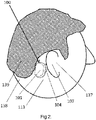
- Fig. 2 is a perspective side overview of the bone conduction hearing aid system 100 of the present invention when it is in position on and attached to a skin 1 13 on the head 139 of a user 138.
- the hearing aid device 101 is connected to the interconnection unit 104 which is connected with an adhesive surface to the skin behind the ear 107 of the user. Sound vibrations are transmitted from the hearing aid device 101 via the interconnection unit 104 to the head of the user to stimulate the hearing organ 137 in the head 139 through bone conduction.
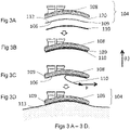
- Figs. 3A-3D are side views of the composition ( Fig. 3A and Fig. 3B ) and the application ( Fig. 3C and Fig.3D ) of the interconnection unit 104 of the bone conduction hearing aid system of the present invention.
- a lateral direction (L) has been marked.
- the interconnection unit 104 has a first side 108, a second side 120 and an adhesive component 109 that may be a double-sided adhesive sheet, and a protective part 110 that is useful to protect a contra-lateral adhesive surface 106 of the adhesive component 109 during transportation and the protective part also prevents the adhesive from attaching to the skin of a user when trying out a suitable curvature version of the interconnection unit 104 for a specific user.
- a user- friendly feature is that the adhesive component (such as a double-sided adhesive sheet) 109 is adapted to be applied to the skin and that it allows oxygen to penetrate therethrough.
- the user may also remove the interconnection unit 104 completely, for example, during a night so that the skin is not permanently interfered with and can "breathe" and function normally when the patient does not need to use the bone conduction hearing aid system 100.
- the adhesive component 109 may also be possible to configure the adhesive component 109 as an adhesive, such as glue, that is directly applied to the second side 120 instead of configuring it as a double-side adhesive sheet.
- the use of a double-sided adhesive sheet may be efficient in manufacturing when applying a contra-lateral adhesive surface 106 to the second side 120.
- the protective part may be a polymer sheet.
- the double-sided adhesive sheet or component 109 has a lateral adhesive surface 112 facing the first side 108.
- Fig. 3B the parts shown in Fig. 3A have been assembled so that the double-sided adhesive sheet 109 has been adhered to the second side 120, and the protective part 110 has been attached to the other side 106 of the double-sided adhesive sheet 109 so that the unit is ready for transportation.
- Fig. 3A the parts shown in Fig. 3A have been assembled so that the double-sided adhesive sheet 109 has been adhered to the second side 120, and the protective part 110 has been attached to the other side 106 of the double-sided adhesive sheet 109 so that the unit is ready for transportation.
- the protective part 1 10 is removed from the adhesive surface 106 of the double-sided adhesive sheet 109 by applying a force (F) to expose the contra-lateral adhesive surface 106.
- the interconnection unit 104 with its double-sided adhesive sheet 109 has been adhesively attached to the skin 1 13 on the head of a user.
- Fig. 4 is a perspective side view of the bone conduction hearing aid system 400 of the present invention.
- a hearing aid device 401 has a first connection portion 403.
- An interconnection unit 404 has a first side 408 and a conical-shaped connection portion 405 and an adhesive surface 406 at its contra-lateral side.
- the bone conduction hearing aid system 400 is similar to the embodiment shown in Fig. 1 , however, the first connection portion 403 and the second connection portion 405 are different, and the interconnection unit 404 has a flexible portion 415.
- the first connection portion 403 is a female coupling that has a flexible portion and a recess defined therein.
- connection portion 405 may be a rigid male coupling so that the flexible female coupling of the connection portion 403 can be snapped onto the male coupling of the connection portion 405. Because an inner diameter of the recess of the flexible female coupling is slightly smaller than an outer diameter of the male coupling, the flexible and elastic female coupling of first connection portion 403 generates a coupling force about the male coupling of the connection portion 405 that keeps the hearing aid device 401 and the interconnection unit 404 together.
- the first connection portion 403 also acts as a member around the protruding second connection portion 405 that hinders the hearing aid device 401 from sliding off the interconnection unit 404 in a sideways direction (i.e. a direction perpendicular to a lateral direction (L)).
- the adhesive surface 406 on the contra-lateral side of the interconnection unit 404 is preferably attached to a skin surface behind the ear of the user (best shown in Fig. 2 ).
- the first side 408 has a rigid portion 414 and a softer flexible and bendable peripheral portion 415 to facilitate adhesion of the adhesive surface 406 to the skin surfaces of various curvatures. Because the rigid portion 414 is sufficiently rigid, it makes it easier for the user to separate connection 403 from connection 405, especially when disconnecting 401 is tilted in relation to 404.
- the interconnection unit 404 both has a non-rigid or flexible portion 415 that is adaptable to the curvature of the skull of the patient while the rigid portion 414 makes it easier to remove the hearing aid device 401 from the interconnection unit 404.
- the interconnection unit 404 has through holes 416 for air and moisture transportation to and from the skin through the interconnection unit 404.
- Figs. 5A and 5B are side views of the bone conduction hearing aid system 100 of the present invention having the hearing aid device 101 and the interconnection unit 104.
- Figs. 5A and 5B are intended to visualize the process when disconnecting the hearing aid device 101 from the interconnection unit 104 by applying a manual tilting force (Fm) on the hearing aid device 101.
- the interconnection unit 104 is attached with an adhesive to the skin 1 13 of the user.
- the manual force (Fm) in contra-lateral direction is applied to a side end 167 of the hearing aid device 101.
- the side end 167 of the device 101 is located away from the first connection portion 103.
- the manual force (Fm) creates a torque that is counter-acted by a counter-acting force (Fc) in a rotation contact spot 160 in the interface between the first connection portion 103 and the second connection portion 105, and by a retention force (Fr).
- the retention force (Fr) is established by the flexible conical second connection portion 105 connected to or inserted into a recess in the rigid female first connection portion 103.
- the retention force (Fr) has been overcome and the hearing aid device 101 is rotated or tilted off from the interconnection unit 104 about the rotation contact spot 160.
- the first side 108 may, preferably, have a sufficiently rigid portion that partially or fully covers the side 108 so that the interconnection unit 104 can counteract the manual force (Fm) against the skin 1 13 and so that the interconnection unit 104 does not undesirably bend because a bending or deformation of the interconnection unit 104 may prevent the manual force 5 (Fm) from disconnecting the hearing aid device 101 from the interconnection unit 104 when the user is applying the manual tilting force (Fm).
- the hearing aid device 101 may be disconnected from the unit 104 with manual forces that includes a force also in contra-lateral direction which minimizes the risk of the interconnection unit 104 being torn off from the skin 1 13 when the device 101 is disconnected from the unit 104.
- FIG. 6 is a cross-sectional side view of a bone conduction hearing aid system 600 of the present invention.
- a hearing aid device 601 has a vibrator 602 and a first connection portion 603.
- An interconnection unit 604 has a second connection portion 605 and an adhesive component 609 being adhesively connectable to a skin 613 of a user.
- the interconnection unit 604 includes an external magnet material 628.
- An implanted unit 629 includes an implanted magnet material 630.
- One of the material 628 and the material 630 has a permanent magnet, and the other one of the material 628 and the material 630 has at least one of a permanent magnet and a ferromagnetic material so that unit 604 and unit 629 are connectable to each other by magnetism.
- the implanted unit 629 is located under the skin 613 and it is fixated to a skull bone 632 with a fixation device such as a fastener 633.
- the magnetic attraction between the external magnet 628 and the implanted magnet 630 presses the interconnection unit 604 towards the skin 613 to enhance sound transmission and to facilitate positioning of the interconnection unit 604 when attaching its adhesive component 609 to the skin 613.
- the interconnection unit 604 and the hearing aid device 601 are substantially retained on the user by the adhesive component 609 of the interconnection unit 604, although the magnetic interaction also contributes to the retention.
- the first connection portion 603 may be a permanent magnet and the second connection portion 605 may include a ferromagnetic material so that also the coupling between the interconnection unit 604 and the hearing aid device 601 is established by magnetic interaction.
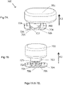
- Figs. 7 A and 7B are perspective side views of a bone conduction hearing aid system 700 of the present invention.
- a hearing aid device 701 is connected to an interconnection unit 704 and in Fig. 7B , the hearing aid device 701 has been disconnected from the interconnection unit 704.
- the bone conduction hearing aid system 700 is similar to the embodiment of Fig. 1 .
- the bone conduction hearing aid system 700 also includes a disconnecting arrangement to facilitate the disconnection of the hearing aid device 701 from the interconnection unit 704.
- Fig. 7A a hearing aid device 701 is connected to an interconnection unit 704 and in Fig. 7B , the hearing aid device 701 has been disconnected from the interconnection unit 704.
- the bone conduction hearing aid system 700 is similar to the embodiment of Fig. 1 .
- the bone conduction hearing aid system 700 also includes a disconnecting arrangement to facilitate the disconnection of the hearing aid device 701 from the interconnection unit 704.
- the hearing aid device 701 has been rotated 90 degrees in a clockwise direction about an axis parallel to the lateral direction (L) in relation to the interconnection unit 704 compared to the position of the hearing aid device 701 in Fig. 7A .
- the hearing aid device 701 has a first connection portion and a hearing aid disconnection portion 725 with a sloping contact surface 727.
- the interconnection unit 704 has a second connection portion 705 and a disconnection portion 724 with a sloping contact surface 726.
- the interconnection unit 704 an adhesive component 709 that can be attached to a skin of a user, as described earlier.
- the lateral direction (L) is marked and a contra-lateral direction is opposite to the lateral direction (L).
- the first connection portion 703 is a rigid female connection portion.
- the second connection portion 705 is a male connection portion that consists of flexible spring arms so that the first connection portion 703 can be snapped on to it.
- the disconnection portion 724 extends further in the lateral direction than the most contra-lateral portion of the disconnection portion 725.
- the sloping contact surface 726 come in contact with the sloping contact surface 727 so that the rotational force creates an axial force parallel to the lateral direction (L) that urges the first connection portion 703 and the second connection portion 705 to disconnect from one another.
- the hearing aid device 701 can be rotated to disconnect it from the interconnection unit 704 instead of pulling it off with a force in lateral direction (L) which may cause the adhesive component 709 to be torn off from the skin of the user when the interconnection unit 704 is adhesively attached to the user.
- the disconnection arrangement may be designed in various ways depending on the design of the coupling.
- the hearing aid device 701 may be disconnected from the interconnection unit 704 by turning the units in a counter-clockwise direction relative to one another.
- a disconnection arrangement may also be designed as a control handle so that a user can press a handle to counteract the coupling force to gently disconnect the hearing aid device 701.
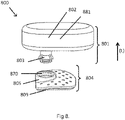
- Fig. 8 is a perspective side view of the bone conduction hearing aid system 800 of the present invention.
- the embodiment shown in Fig. 8 is very similar to the embodiment shown in Fig. 1 except that the positions of the male and female connections have been switched so that the female coupling is on the interconnection unit while the male coupling is on the hearing aid device.
- a hearing aid device 801 has a first male connection portion 803.
- An interconnection unit 804 has a second connection portion 805 and an adhesive component 809.
- the first portion 803 is a flexible male coupling so that it can be removably snapped into the female portion 805.
- the female connection portion 805 has a recess 870 defined therein so that the first connection portion 803 can be retained to the portion 805.
- the way the male portion 803 connects to the female portion 805 is substantially similar to the embodiment of Fig. 1 except that the male and female portions have been switched. More particularly, the first connection portion 803 generates a coupling force that keeps the hearing aid device 801 and the interconnection unit 804 together.
- the female second connection portion 805 also acts as a member around the portion 805 to hinder the hearing aid device 801 to slide off from the unit 804 in a sidewise direction (i.e. a direction perpendicular to a lateral direction (L)).
- the adhesive segment 809 allows the interconnection unit 804 to be removably connected to a skin of the user.
- the hearing aid device 801 includes a tinnitus masking signal generator 881. The signal from the tinnitus masking signal generator 881 is transferred into vibrations by the vibrator 802 that is also located in the hearing aid device 801, and the vibrations is then transmitted to the hearing organ through bone conduction.
- the vibrator of the present invention may be any suitable type of vibrator such as an electromagnetic vibrator or a piezoelectric vibrator.
- the amplifier of the hearing aid device may, for example, include digital processing, directional microphones, noise reduction, feedback suppression and other electronic and software features that are beneficial and used in any suitable type of regular hearing aid.
- the hearing aid device may consist of one housing unit where all electronics are included, or it may consist of two or more separate housing units where different parts of the electronics are included in the different housings and where the separate housing units communicate with each other via wire or wireless communication.
- the interconnection unit may have a bulb or knob in part of the area facing the skin to create a local light pressure against the skin to further enhance sound transmission.
- the adhesive patch By stretching the prior art adhesive patch over the hearing aid device, the adhesive patch also provides an inwardly directed pressure onto the hearing aid system that, in turn, is pressed against the skin.
- the adhesive attachment area on the head of the user may then also have to be quite large.
- the hearing aid system of the present invention is preferably placed and adhered to the area of the skin behind the ear that does not have any hair growing thereon. It was unexpectedly realized that although no or very little pressure is being applied on the skin by the adhesive, the vibrations from the hearing aid system are properly and effectively being conveyed into the skull of the user while holding the hearing aid system in place so that the user can move without the hearing aid system undesirably moving or falling off.
- the adhesive carrier can at least partly be located between the bone conductor of the hearing aid device and the skin.
- the adherence between the interconnection unit and the skin is sufficiently strong to make it possible to use a properly designed mechanically stable coupling between the interconnection unit and the hearing aid device so that the hearing aid device can conveniently be connected to and disconnected from the interconnection unit without undesirably moving or tearing off the interconnection unit from the skin.
- an adhesively attached bone conductor can be designed in one housing without feedback problems and without requiring a cord to a separate unit. An important feature of the present invention is thus that it is not necessary to apply a pressure on the skin in order to be able to properly and effectively convey the vibrations from the hearing aid unit into the skull of the user and to hold the hearing aid system in place while the user is moving.
Landscapes
- Health & Medical Sciences (AREA)
- General Health & Medical Sciences (AREA)
- Otolaryngology (AREA)
- Neurosurgery (AREA)
- Physics & Mathematics (AREA)
- Engineering & Computer Science (AREA)
- Acoustics & Sound (AREA)
- Signal Processing (AREA)
- Details Of Audible-Bandwidth Transducers (AREA)
Abstract
Description
- The present invention relates to a hearing aid system providing bone conduction hearing.
- Bone conduction is the conduction of sound to the inner ear through the bones of the skull, and a bone conduction hearing aid, or bone conductor, is a device that stimulates through bone conduction. Other types of hearing aids may instead directly stimulate the tympanic membrane, the middle ear ossicles, the round window, the oval window or the cochlear fluid. Several different types of bone conduction hearing aids are available. A bone conduction hearing aid may amplify sound or it may also work as a tinnitus masker. A bone conductor may also be used in audiometry to determine bone conduction hearing thresholds. Current bone conductors include however several drawbacks, as described below.
- The traditional bone conductor consists of a hearing aid with a vibrator that is pressed against the head behind the ear by a spring arrangement extending from the other side of the head. The steel spring arrangement is sometimes built into an eyeglass frame. The vibrations are transmitted through the skin and the skull bone into the inner ear. For the traditional bone conductors with a spring arrangement around the head, the constant pressure against the skull bone often causes headaches and skin irritation. The spring arrangement is also bulky and is not a practical or user friendly solution.
- Another type of established bone conductor, which is sometimes called a direct bone conductor, includes a vibrator, which is directly and firmly connected to an anchoring component that is anchored to the skull bone through which the vibrations are directly transmitted from the vibrator to the skull bone. The vibrations do not pass through the skin on its way from the vibrator to the skull bone. This type of bone conductor may be designed with a permanent skin penetration which may lead to problems with skin infections. If this type of bone conductor is instead designed with an implanted vibrator and where energy are transmitted from an external hearing aid there is a significant energy loss when transmitting the energy with an inductive link through the skin. Another drawback is that the vibrator cannot easily be repaired if it breaks down.
- Another type of bone conductor is a type where the vibrator is placed in an external unit outside the skin and where this external unit is kept in place through a magnetic attachment to a part that is anchored to the skull bone and implanted under the skin. In this arrangement, the signal from the external part is passing through the skin to the implanted part and the skull bone. For this type of bone conductor, surgery is still required and the magnetic force may cause skin necrosis due to the constant pressure against the skin and the hearing aid may also easily fall off.
-
JP 201 1087142 (A JP 201 1087142 (A - There is a need for a more effective bone conduction hearing aid system that is reliable and does not have the drawbacks discussed above.
- The present invention provides an effective solution to the above- outlined problems of bone conduction hearing aids. More particularly, the bone conduction hearing aid system of the present invention has a hearing aid device with a vibrator disposed in a hearing aid housing. The hearing aid device has also a first connection portion. Furthermore, the bone conduction hearing aid system of the present invention has an interconnection unit that has a first side, having a second connection portion, and a second side at least partly provided with an adhesive component. The second side is configured to, when in use, face a skin of a user of the bone conduction hearing aid system. The first connection portion of the hearing aid device is connectable to the second connection portion of the interconnection unit so that these two portions form a coupling. The present invention allows the interconnection unit and the adhesive surface to be at least partly positioned between the hearing aid device and the skin of the user to enable a practical and efficient use of the bone conduction hearing aid system. The present invention also allows the hearing device to be connected to and disconnected from the interconnection unit without having to, at the same time, connect or disconnect the interconnection unit to the skin of the user.
- The bone conduction hearing aid system of the present invention is preferably configured so that the adhesive component is a separately arranged adhesive sheet having a first adhesive surface being connectable to the second surface of the interconnection unit, and a second adhesive surface configured to, when in use, being connectable to the skin of the user of the bone conduction hearing device. This is an efficient way to manufacture the adhesive component on the interconnection unit and may also enable changing a worn out adhesive component of the interconnection unit to a new adhesive component.
- The bone conduction hearing aid system of the present invention is preferably configured with at least one through hole extending from the first side to the second side of the interconnecting unit. This allows for moisture and air transportation through the interconnection unit which is beneficial to the skin of the user to which the interconnection unit can be attached with the adhesive component. Preferably, the interconnection unit has several through-holes defined therein and the interconnection unit may also have a porous material for the same purpose.
- In a preferred embodiment of the bone conduction hearing aid system of the present invention, the interconnection unit has a protective sheet disconnectably arranged on the adhesive component, such that the adhesive component is sandwiched between the protective sheet and the interconnection unit. The protective sheet protects the adhesive component during transportation.
- In a preferred embodiment of the bone conduction hearing aid system of the present invention, the hearing aid device is rotatable about a rotation spot i.e. in relation to the interconnection unit about a geometric center axis extending through a respective center portion of the first and the second connection portions during use of the bone conduction hearing aid system. With the hearing aid device being rotatable to at least part of a turn, it is possible to somewhat adjust the orientation of the hearing aid device on the head of the user when the hearing aid device is connected to the interconnection unit that is adhesively attached to the skin of the user. This is practical since the orientation of the hearing aid device on the head of the user can then be adjusted without having to tear off the interconnection unit from the skin to reposition it or to attach a new interconnection unit at a new position on the skin.
- In a preferred embodiment of the bone conduction hearing aid system of the present invention, the second connection portion is positioned non-centrically on the first side of the interconnection unit. The interconnection unit is preferably positioned on the naturally non-hair baring area behind the ear of the user since the adhesive attachment of the interconnection unit would be less efficient on a hair baring area. The hearing aid device should not touch the outer ear of the user since this may cause feedback and poor sound quality as well as discomfort. With the second connection portion being non-centrically positioned on the first side, towards a rear portion of the interconnection unit when the interconnection unit is attached to the skin behind the ear of a user, the hearing aid device is positioned further back to the rear, i.e. further away from the outer ear which reduces the risk of the hearing aid device touching the outer ear. It is desirable not to have to shave off hair behind the naturally non-hair baring area behind the ear, and the positioning of the second connection portion towards the rear portion of the interconnection unit increases the chances of the hearing aid not touching the outer ear and the interconnection unit still being adhesively attached to the naturally non-hair baring area behind the ear of the user.
- In a preferred embodiment of the bone conduction hearing aid system of the present invention, one of the first and the second connection portion is a female connection portion and the other one of the first and the second connection portion is a male connection portion. Preferably, the male connection portion is at least partly insertable into the female connection portion. This is an efficient design that makes the coupling stable and robust and prevents the hearing aid device from sliding off sidewise from the interconnection unit.
- In a preferred embodiment of the bone conduction hearing aid system of the present invention, the second connection portion is defining a geometric plane. The geometric plane is perpendicular to a geometric center axis extending through a respective center portion of the first and the second connection portions during use of the bone conduction hearing aid system. Preferably, the first connection portion is configured to be tiltably disconnectable to the second connection portion in relation to the geometric plane. This design allows the first connection portion to be disconnected from the second connection portion by applying a tilting force on the hearing aid device when the hearing aid device is connected to the adhesively attached interconnection unit. This significantly reduces the risk of tearing the adhesively attached interconnection unit off from the skin of the user compared to if the hearing aid device would have been disconnected from the interconnection unit through a straight pulling force in a lateral direction. The lateral direction may be a direction pointing out from the head of a user when the bone conduction hearing aid system is worn by the user, and a contra-lateral direction may be an opposite direction to the lateral direction}. The coupling is preferably configured so that the hearing aid device can be disconnected from the interconnection unit without having to manually hold the interconnection unit to the skin to avoid the interconnection unit from inadvertently being torn off from the skin.
- In a preferred embodiment of the bone conduction hearing aid system of the present invention, the hearing aid device is configured to be rotatably disconnectable from the interconnection unit about a geometric center axis extending through a respective center portion of the first and the second connection portions during use of the bone conduction hearing aid system. This configuration may comprise a disconnecting arrangement having a sloped contact surface in operative engagement with a rotational disconnection surface so that a manually applied rotational force is directed to overcome the connection force keeping the hearing aid device and the interconnection unit connected to each other. In this way, the hearing aid device may be disconnected from the interconnection unit without having to pull the hearing aid device in the lateral direction to disconnect it from the interconnection unit which may then be undesirably torn off from the skin of the user.
- In a preferred embodiment of the bone conduction hearing aid system of the present invention, a portion of the first side is rigid in relation to the remaining portion of the first side, and the second connection portion is positioned on the rigid portion of the first side. It is desirable that at least a part of the interconnection unit is sufficiently rigid and that this part is in sufficiently rigid connection with the second connection portion so that the interconnection unit is not significantly deformed by the torque it is exposed to when, for example, tilting the hearing aid device to disconnect the hearing aid device from the interconnection unit, since significant deformation or bending of the interconnection unit might prevent disconnection of the hearing aid device through tilting. Deformation may also increase the risk of tearing off the interconnection unit from the skin. It may, however, be advantageous to still have part of the interconnection unit be more flexible since it can then more easily adapt to a curvature of the head of a user. A part of the interconnection unit may be transformable from a soft to a rigid state so that it can be more easily shaped to a curvature of the head of a user, but still be sufficiently rigid when in use. The interconnection unit may also be individually manufactured to fit the head curvature of a user by using any available technology for this.
- In a preferred embodiment of the bone conduction hearing aid system of the present invention, one of the first and the second connection portions has a permanent magnet, and the other of the first and the second connection portion has at least one of a permanent magnet and a ferromagnetic material so that the first and second connection portions are connectable to each other by magnetism. A magnetic coupling between the hearing aid device and the interconnection unit may be an efficient and durable connection. The coupling may alternatively be configured with, for example, one of the first connection portion and the second connection portion that is flexible in relation to the other of the first connection portion and the second connection portion which may be a more cost efficient solution than a magnetic coupling. The second connection portion may, for example, be a flexible polymer snap connection portion that is flexibly connectable to the first connection-portion. This is an efficient design because the second connection may then be less durable than the first connection portion, and because the interconnection unit is frequently replaced, it is acceptable if the durability of the second connection portion is shorter than the durability of the first connection portion on the hearing aid device which can then be made quite robust. In a preferred embodiment of the present invention, there is a first contact surface of the second connection portion and a second contact surface of the first connection- portion, where the first contact surface and the second contact surface face each other when the first connection portion is connected to the second connection portion. Preferably, the second contact surface is made of a material that has an increased resistance to wear in comparison to the material of the first contact surface.
- In a preferred embodiment of the bone conduction hearing aid system of the present invention, the hearing aid device has a vibrator suspension device for acoustically isolating the vibrator from the housing of the hearing aid device which is valuable to reduce the risk for acoustic feedback. The bone conduction hearing aid system of the present invention may also have a second high-frequency vibrator that has a resonance frequency higher than a resonance frequency of the vibrator above to further boost the acoustic high frequency performance.
- In a preferred embodiment of the bone conduction hearing aid system of the present invention, the second connection portion of the interconnection unit is provided with an adhesive component so that the second connection portion is adhesively attachable to the first connection portion of the hearing aid device. The interconnection unit may then be a double sided adhesive sheet that is attached to the hearing aid device and the hearing aid with the double sided adhesive sheet can then be attached to the head of the user. When the hearing aid device is removed from the head also the interconnection unit, being a double sided adhesive sheet, is removed from the head. The double sided adhesive sheet may then be changed before attaching the hearing aid device to the head again. This alternative design may be efficient since it may offer a low profile and cost efficient design of the interconnection unit.
- In a preferred embodiment of the bone conduction hearing aid system of the present invention, the bone conduction hearing aid system further has an implanted unit under the skin that includes an implanted magnetic material. Preferably, there is an external magnetic material in at least one of either the hearing aid device or the interconnection unit, and a permanent magnet in at least one of either the implanted magnetic material or the external magnetic material so that the implanted magnetic material is in operative engagement with the external magnetic material. With this design, the positioning of the adhesive interconnection unit on the head of the user is facilitated. This design may also contribute to improving sound transmission by creating a slight pressure on the skin. The bone conduction hearing aid system of the present invention may also comprise an ear hook to further ensure that the user does not drop the device.
- The present invention has several advantages and allows a bone conductor to be retained on the user with an adhesive still allowing the user to take the hearing aid device on and off without having to tear the adhesive off the skin.
- A substantial part of the interconnection unit can be located between the hearing aid device and the skin of the user. The bone conduction hearing aid system can then be considerably limited in size on the head of the user. It is in many cases possible to fully place the interconnection unit on the naturally non-hair baring area behind the ear without requiring arrangements on other parts on the head of the user. The hearing aid device can be easily connected to and disconnected from the interconnection unit without the coupling being sensitive to water and dirt when, for example, connecting the hearing aid device to the interconnection unit after taking a shower (the hearing aid device may not be waterproof whereas the interconnection unit may stay attached to the skin of the user also during for example a shower).
- Other advantages of the bone conduction hearing aid system of the present invention are that the hearing aid device can be standardized since the coupling to the interconnection unit can be the same for more or less all patients which is important since the hearing aid is a quite expensive. The interconnection unit that is more frequently changed and fairly cost efficient to manufacture can, however, easily be manufactured in various shapes and sizes to fit different users.
- Another advantage of the bone conduction hearing aid system of the present invention is that it enables the attachment of the interconnection unit to the skin to be a separate process from the connection procedure of the hearing aid device. With the bone conduction hearing aid system of the present invention, the attachment of the adhesive interconnection unit can be done accurately in a controlled situation, for example, in front of a mirror at home, and the interconnection unit will then stay in this position until it is removed after one or several days of usage. The hearing aid device may be connected to the interconnection unit in less controlled situations during the day, and as long as the interconnection unit is correctly placed, the hearing aid device will automatically be correctly positioned on the head, for example, when connecting the hearing aid device to the interconnection unit on the beach after a swim. The interconnection unit of the present invention which adheres to the skin can be changed at an interval that is suitable for the skin, which may be every night or it may, for example, be more seldom like every third day or once a week. The skin can then rest during a night when the interconnection unit is not attached.
- The bone conduction hearing aid system of the present invention can be used as a long term treatment for patients with, for example, conductive hearing losses. The bone conduction hearing aid system of the present invention can also be efficient for the rehabilitation of temporary hearing losses due to various middle ear conditions, and it may also be used as a temporary hearing solution to evaluate bone conduction hearing for a patient to decide whether a surgical bone conduction bone conduction hearing aid should be applied on a patient.
- The bone conduction hearing aid system of the present invention may also be a bone conduction tinnitus masker used to reduce the handicap of tinnitus, and it may also be applied as a bone conduction stimulator in audiometry to determine bone conduction hearing. In a preferred embodiment of the bone conduction hearing aid system of the present invention, the bone conduction hearing aid system has a signal generator for tinnitus masking.
- As described above, the bone conduction hearing aid system of the present invention includes a unique combination of technologies and provides new solutions and several advantages to meet complex user requirements.
-
-
Fig. 1 is a perspective side view overviewing the bone conduction hearing aid system of the present invention when the hearing aid device is not connected to the interconnection unit, and where the vibrator of the hearing aid device has been visualized; -
Fig. 2 is a perspective side view overviewing the bone conduction hearing aid system of the present invention when the bone conduction hearing aid system is connected to a user; -
Fig. 3A is a side view of the interconnection unit of the present invention with an adhesive component and protective part separated from the interconnection unit; -
Fig. 3B is a side view of the embodiment shown inFig. 3A with the adhesive component and protective part attached to the interconnection unit; -
Fig. 3C is a side view of the embodiment shown inFig. 3B with the protective part partially removed; -
Fig. 3D is a side view of the embodiment shown inFig. 3C with the protective part fully removed and the embodiment attached to a skin portion of a user; -
Fig. 4 is a perspective side view of an embodiment of the bone conduction hearing aid system of the present invention with a flexible female connection portion of the hearing aid device and a corresponding male connection portion on the first side of the interconnection unit; -
Fig. 5A is a side view of an alternative embodiment of the bone conduction hearing aid system of the present invention, and -
Fig. 5B is a side view of the embodiment shown inFig. 5A in a tilted position; -
Fig. 6 is a cross-sectional side view of an embodiment of the bone conduction hearing aid system of the present invention including magnetic material in an implanted unit under the skin and a corresponding magnetic material in the interconnection unit; -
Fig. 7 A is a perspective side view of an embodiment of the bone conduction hearing aid system of the present invention in a connected position; -
Fig. 7B is a perspective side view of the embodiment shown inFig. 7A in a disconnected position; and -
Fig. 8 is a perspective side view of an embodiment of the bone conduction hearing aid system of the present invention with a flexible male connection portion of the hearing aid device and a corresponding female connection portion on a first side of the interconnection unit. -
Fig. 1 is a perspective side overview of the bone conductionhearing aid system 100 of the present invention. Ahearing aid device 101 has a vibrator 102 (shown as a cross-sectional view) disposed therein. Thevibrator 102 is connected to afirst connection portion 103 of thehearing aid device 101. Aninterconnection unit 104 has afirst side 108 and a second side (not shown) opposite to thefirst side 108. Thefirst side 108 has asecond connection portion 105. Thefirst connection portion 103 and thesecond connection portion 105 form a coupling since they are connectable to each other. The second side has anadhesive component 109. The lateral direction (L) has been marked. A contra-lateral direction may be a direction opposite to the lateral direction (L) and a lateral side of a component may be a side facing the lateral direction and a contra-lateral side may be facing a contra-lateral direction. Thefirst side 108 may, for example, be a lateral side of theinterconnection unit 104. Theadhesive component 109 has anadhesive surface 106 at the contra-lateral side of theadhesive component 109. Theadhesive surface 106 can be removably connected to the skin on the head of a user (best shown inFig. 2 ) and thefirst connection portion 103 can be removably connected to thesecond connection portion 105 of theinterconnection unit 104 by inserting a portion of thesecond connection portion 103 into a cavity defined inside theportion 105. The,hearing aid device 101 can then transmit bone conduction vibrations to the hearing organ of the user (seeFig. 2 ). The lateral direction (L) may be defined as the direction pointing out from the patient's head when the bone conductionhearing aid system 100 is connected to the skin of the patient. One useful feature is that the patient may simply remove thehearing aid device 101 by snapping theconnection portion 103 from thesecond connection portion 105, and it may, preferably, require less force to remove theconnection portion 103 from theconnection portion 105 compared to removing theadhesive component 109 from the skin. In this way, the patient may easily remove thehearing aid device 101 from theinterconnection unit 104 without inadvertently removing theinterconnection unit 104 from the skin of the patient. To ensure this, thefirst connection portion 103 can be disconnected from thesecond connection portion 105 by tilting it in relation to theconnection portion 105, thus generating significantly less pulling forces on the skin from theadhesive surface 106 when disconnecting thehearing aid device 101 from theinterconnection unit 104 adhesively attached to a user. To enable disconnecting thehearing aid device 101 from theunit 104 with a tilting force, theunit 104 is sufficiently rigid so that theunit 104 is not deformed or bent when applying a tilting force since such deformation or bending may prevent the intended disconnection of thehearing aid device 101 from theinterconnection unit 104 by using the above described tilting force. - Preferably, the connection between
connection portions hearing aid device 101 cannot slide in a sideways direction relative to theinterconnection unit 104 i.e. in a direction that is perpendicular to the lateral direction (L). Thefirst connection portion 103 is, preferably, a substantially rigid female connection portion. Thesecond connection portion 105 is, preferably, a male connection portion that consists of flexible and elastic protruding spring arms so that theportion 103 can be snapped onto theportion 105. It is also possible to makeportion 105 rigid andportion 103 flexible and elastic. When thefirst connection portion 103 has been snapped onto thesecond connection portion 105, the flexiblesecond connection portion 105 establishes a coupling force that keeps thehearing aid device 101 and theinterconnection unit 104 together and allows sound vibrations to be transmitted from thevibrator 102 to theinterconnection unit 104. Theportions hearing aid device 101 is magnetically attached to theinterconnection unit 104. If magnets are used, it is also preferable that theportions portion 103 relative toportion 105. - The
hearing aid device 101 may, in general, also include a microphone, electronics, battery and volume control which are not shown in the drawings. Thehearing aid device 101 may include a signal generator to generate for example a noise signal for tinnitus masking or tones for audiometry. Thehearing aid device 101 may also be connected with a cord to a conventional audiometer for audiometry. - Preferably, the
interconnection unit 104 has a plurality of openings defined therethrough so that air and moisture may be transported through theinterconnection unit 104 to reach portions of the patient's skin that is below thesurface 106, andopening 1 16 is one such opening that has been marked. - The female
first connection portion 103 can be turned about the center axis of the coupling relative to the malesecond connection portion 105 connected thereto. This is useful since it is then possible to adjust the orientation of thehearing aid device 101 when it is connected to theinterconnection unit 104 attached to the user. Preferably, there should be sufficient friction between thefirst connection portion 103 and thesecond connection portion 105 to ensure that thehearing aid device 101 is still kept in an accurate position. Thefirst side 108 has afront portion 141 and arear portion 142. Thefront portion 141 is closer to the ear of the user than therear portion 142 when the interconnection portion is adhered to the skin behind the ear (best shown inFig. 2 ). Thesecond connection portion 105 should be eccentrically positioned on theinterconnection unit 104 so that the portion is off-center and closer to or at therear portion 142. One advantage is that thehearing aid device 101 is also positioned further to the rear to avoid thehearing aid device 101 from touching the outer ear of a user. Thehearing aid device 101 may also include avibrator suspension device 165 that suspends thevibrator 102 from the housing of thehearing aid device 101 to minimize feedback problems. - The
second connection portion 105 may be an elastic plastic snapping device and thefirst connection portion 103 may be a more durable female connection so that the wear is on themale connection portion 105 of theinterconnection unit 104 which is frequently changed, instead of the wear being on thehearing aid device 101 which would need to be sent to repair when worn out. However, it is also possible to design theportions male portion 105 is more wear resistant than thefemale portion 103 and so that thefemale portion 103 is more flexible and elastic compared to themale portion 105. To achieve a stable and durable coupling, both the female 103 and male 105 connection portions include some substantially rigid mechanical components. The coupling of the bone conductionhearing aid system 100 of the present invention is, preferably, an arrangement between thehearing aid device 101 and theinterconnection unit 104 that is quite stiff when these are connected to each other to ensure an efficient transmission of the vibrations from thevibrator 102 of thehearing aid device 101 to theinterconnection unit 104 without damping or distortion of the signal. -
Fig. 2 is a perspective side overview of the bone conductionhearing aid system 100 of the present invention when it is in position on and attached to askin 1 13 on thehead 139 of auser 138. Thehearing aid device 101 is connected to theinterconnection unit 104 which is connected with an adhesive surface to the skin behind theear 107 of the user. Sound vibrations are transmitted from thehearing aid device 101 via theinterconnection unit 104 to the head of the user to stimulate thehearing organ 137 in thehead 139 through bone conduction. -
Figs. 3A-3D are side views of the composition (Fig. 3A and Fig. 3B ) and the application (Fig. 3C and Fig.3D ) of theinterconnection unit 104 of the bone conduction hearing aid system of the present invention. A lateral direction (L) has been marked. InFig. 3A the following separated parts are shown before assembly in manufacturing: theinterconnection unit 104 has afirst side 108, asecond side 120 and anadhesive component 109 that may be a double-sided adhesive sheet, and aprotective part 110 that is useful to protect a contra-lateraladhesive surface 106 of theadhesive component 109 during transportation and the protective part also prevents the adhesive from attaching to the skin of a user when trying out a suitable curvature version of theinterconnection unit 104 for a specific user. A user- friendly feature is that the adhesive component (such as a double-sided adhesive sheet) 109 is adapted to be applied to the skin and that it allows oxygen to penetrate therethrough. It is also possible for the user to remove theinterconnection unit 104 completely, for example, during a night so that the skin is not permanently interfered with and can "breathe" and function normally when the patient does not need to use the bone conductionhearing aid system 100. It may also be possible to configure theadhesive component 109 as an adhesive, such as glue, that is directly applied to thesecond side 120 instead of configuring it as a double-side adhesive sheet. However, the use of a double-sided adhesive sheet may be efficient in manufacturing when applying a contra-lateraladhesive surface 106 to thesecond side 120. The protective part may be a polymer sheet. The double-sided adhesive sheet orcomponent 109 has a lateraladhesive surface 112 facing thefirst side 108. Instead of using an adhesive on thesurface 1 12, it is also possible to use other removable attachment mechanisms such as Velcro or separate glue. Since thesheet 109 may be removably attached to thesecond side 120 it is also possible to change thesheet 109 on theinterconnection unit 104 if this is more cost efficient than just to take a newcomplete interconnection unit 104 that includes anew sheet 109. InFig. 3B , the parts shown inFig. 3A have been assembled so that the double-sided adhesive sheet 109 has been adhered to thesecond side 120, and theprotective part 110 has been attached to theother side 106 of the double-sided adhesive sheet 109 so that the unit is ready for transportation. InFig. 3C , theprotective part 1 10 is removed from theadhesive surface 106 of the double-sided adhesive sheet 109 by applying a force (F) to expose the contra-lateraladhesive surface 106. InFig. 3D , theinterconnection unit 104 with its double-sided adhesive sheet 109 has been adhesively attached to theskin 1 13 on the head of a user. -
Fig. 4 is a perspective side view of the bone conductionhearing aid system 400 of the present invention. Ahearing aid device 401 has afirst connection portion 403. Aninterconnection unit 404 has afirst side 408 and a conical-shapedconnection portion 405 and anadhesive surface 406 at its contra-lateral side. The bone conductionhearing aid system 400 is similar to the embodiment shown inFig. 1 , however, thefirst connection portion 403 and thesecond connection portion 405 are different, and theinterconnection unit 404 has aflexible portion 415. Thefirst connection portion 403 is a female coupling that has a flexible portion and a recess defined therein. Theconnection portion 405 may be a rigid male coupling so that the flexible female coupling of theconnection portion 403 can be snapped onto the male coupling of theconnection portion 405. Because an inner diameter of the recess of the flexible female coupling is slightly smaller than an outer diameter of the male coupling, the flexible and elastic female coupling offirst connection portion 403 generates a coupling force about the male coupling of theconnection portion 405 that keeps thehearing aid device 401 and theinterconnection unit 404 together. Thefirst connection portion 403 also acts as a member around the protrudingsecond connection portion 405 that hinders thehearing aid device 401 from sliding off theinterconnection unit 404 in a sideways direction (i.e. a direction perpendicular to a lateral direction (L)). Theadhesive surface 406 on the contra-lateral side of theinterconnection unit 404 is preferably attached to a skin surface behind the ear of the user (best shown inFig. 2 ). Thefirst side 408 has arigid portion 414 and a softer flexible and bendableperipheral portion 415 to facilitate adhesion of theadhesive surface 406 to the skin surfaces of various curvatures. Because therigid portion 414 is sufficiently rigid, it makes it easier for the user to separateconnection 403 fromconnection 405, especially when disconnecting 401 is tilted in relation to 404. It is an important feature that theinterconnection unit 404 both has a non-rigid orflexible portion 415 that is adaptable to the curvature of the skull of the patient while therigid portion 414 makes it easier to remove thehearing aid device 401 from theinterconnection unit 404. Theinterconnection unit 404 has throughholes 416 for air and moisture transportation to and from the skin through theinterconnection unit 404. -
Figs. 5A and 5B are side views of the bone conductionhearing aid system 100 of the present invention having thehearing aid device 101 and theinterconnection unit 104.Figs. 5A and 5B are intended to visualize the process when disconnecting thehearing aid device 101 from theinterconnection unit 104 by applying a manual tilting force (Fm) on thehearing aid device 101. Theinterconnection unit 104 is attached with an adhesive to theskin 1 13 of the user. InFig. 5A , the manual force (Fm) in contra-lateral direction is applied to aside end 167 of thehearing aid device 101. Theside end 167 of thedevice 101 is located away from thefirst connection portion 103. The manual force (Fm) creates a torque that is counter-acted by a counter-acting force (Fc) in arotation contact spot 160 in the interface between thefirst connection portion 103 and thesecond connection portion 105, and by a retention force (Fr). The retention force (Fr) is established by the flexible conicalsecond connection portion 105 connected to or inserted into a recess in the rigid femalefirst connection portion 103. InFig. 5B , the retention force (Fr) has been overcome and thehearing aid device 101 is rotated or tilted off from theinterconnection unit 104 about therotation contact spot 160. As explained in more detail above, thefirst side 108 may, preferably, have a sufficiently rigid portion that partially or fully covers theside 108 so that theinterconnection unit 104 can counteract the manual force (Fm) against theskin 1 13 and so that theinterconnection unit 104 does not undesirably bend because a bending or deformation of theinterconnection unit 104 may prevent the manual force 5 (Fm) from disconnecting thehearing aid device 101 from theinterconnection unit 104 when the user is applying the manual tilting force (Fm). With this configuration, thehearing aid device 101 may be disconnected from theunit 104 with manual forces that includes a force also in contra-lateral direction which minimizes the risk of theinterconnection unit 104 being torn off from theskin 1 13 when thedevice 101 is disconnected from theunit 104. -
Fig. 6 is a cross-sectional side view of a bone conductionhearing aid system 600 of the present invention. Ahearing aid device 601 has avibrator 602 and afirst connection portion 603. Aninterconnection unit 604 has asecond connection portion 605 and anadhesive component 609 being adhesively connectable to askin 613 of a user. Theinterconnection unit 604 includes anexternal magnet material 628. An implantedunit 629 includes an implantedmagnet material 630. One of thematerial 628 and thematerial 630 has a permanent magnet, and the other one of thematerial 628 and thematerial 630 has at least one of a permanent magnet and a ferromagnetic material so thatunit 604 andunit 629 are connectable to each other by magnetism. The implantedunit 629 is located under theskin 613 and it is fixated to askull bone 632 with a fixation device such as afastener 633. The magnetic attraction between theexternal magnet 628 and the implantedmagnet 630 presses theinterconnection unit 604 towards theskin 613 to enhance sound transmission and to facilitate positioning of theinterconnection unit 604 when attaching itsadhesive component 609 to theskin 613. Theinterconnection unit 604 and thehearing aid device 601 are substantially retained on the user by theadhesive component 609 of theinterconnection unit 604, although the magnetic interaction also contributes to the retention. Thefirst connection portion 603 may be a permanent magnet and thesecond connection portion 605 may include a ferromagnetic material so that also the coupling between theinterconnection unit 604 and thehearing aid device 601 is established by magnetic interaction. -
Figs. 7 A and 7B are perspective side views of a bone conductionhearing aid system 700 of the present invention. InFig. 7A , ahearing aid device 701 is connected to aninterconnection unit 704 and inFig. 7B , thehearing aid device 701 has been disconnected from theinterconnection unit 704. The bone conductionhearing aid system 700 is similar to the embodiment ofFig. 1 . However, the bone conductionhearing aid system 700 also includes a disconnecting arrangement to facilitate the disconnection of thehearing aid device 701 from theinterconnection unit 704. InFig. 7B , thehearing aid device 701 has been rotated 90 degrees in a clockwise direction about an axis parallel to the lateral direction (L) in relation to theinterconnection unit 704 compared to the position of thehearing aid device 701 inFig. 7A . Thehearing aid device 701 has a first connection portion and a hearingaid disconnection portion 725 with asloping contact surface 727. Theinterconnection unit 704 has asecond connection portion 705 and adisconnection portion 724 with asloping contact surface 726. Theinterconnection unit 704 anadhesive component 709 that can be attached to a skin of a user, as described earlier. The lateral direction (L) is marked and a contra-lateral direction is opposite to the lateral direction (L). Preferably, thefirst connection portion 703 is a rigid female connection portion. Preferably, thesecond connection portion 705 is a male connection portion that consists of flexible spring arms so that thefirst connection portion 703 can be snapped on to it. Thedisconnection portion 724 extends further in the lateral direction than the most contra-lateral portion of thedisconnection portion 725. When thehearing aid device 701 is rotated in the clockwise direction about a geometric center axis (parallel to the lateral direction) extending through a respective center portion of the first and the second connection infig. 7A , the slopingcontact surface 726 come in contact with thesloping contact surface 727 so that the rotational force creates an axial force parallel to the lateral direction (L) that urges thefirst connection portion 703 and thesecond connection portion 705 to disconnect from one another. In this way, thehearing aid device 701 can be rotated to disconnect it from theinterconnection unit 704 instead of pulling it off with a force in lateral direction (L) which may cause theadhesive component 709 to be torn off from the skin of the user when theinterconnection unit 704 is adhesively attached to the user. The disconnection arrangement may be designed in various ways depending on the design of the coupling. For example, thehearing aid device 701 may be disconnected from theinterconnection unit 704 by turning the units in a counter-clockwise direction relative to one another. A disconnection arrangement may also be designed as a control handle so that a user can press a handle to counteract the coupling force to gently disconnect thehearing aid device 701. -
Fig. 8 is a perspective side view of the bone conductionhearing aid system 800 of the present invention. The embodiment shown inFig. 8 is very similar to the embodiment shown inFig. 1 except that the positions of the male and female connections have been switched so that the female coupling is on the interconnection unit while the male coupling is on the hearing aid device. More particularly, ahearing aid device 801 has a firstmale connection portion 803. Aninterconnection unit 804 has asecond connection portion 805 and anadhesive component 809. Thefirst portion 803 is a flexible male coupling so that it can be removably snapped into thefemale portion 805. Thefemale connection portion 805 has arecess 870 defined therein so that thefirst connection portion 803 can be retained to theportion 805. The way themale portion 803 connects to thefemale portion 805 is substantially similar to the embodiment ofFig. 1 except that the male and female portions have been switched. More particularly, thefirst connection portion 803 generates a coupling force that keeps thehearing aid device 801 and theinterconnection unit 804 together. The femalesecond connection portion 805 also acts as a member around theportion 805 to hinder thehearing aid device 801 to slide off from theunit 804 in a sidewise direction (i.e. a direction perpendicular to a lateral direction (L)). Theadhesive segment 809 allows theinterconnection unit 804 to be removably connected to a skin of the user. Thehearing aid device 801 includes a tinnitusmasking signal generator 881. The signal from the tinnitus maskingsignal generator 881 is transferred into vibrations by thevibrator 802 that is also located in thehearing aid device 801, and the vibrations is then transmitted to the hearing organ through bone conduction. - The vibrator of the present invention may be any suitable type of vibrator such as an electromagnetic vibrator or a piezoelectric vibrator. The amplifier of the hearing aid device may, for example, include digital processing, directional microphones, noise reduction, feedback suppression and other electronic and software features that are beneficial and used in any suitable type of regular hearing aid. The hearing aid device may consist of one housing unit where all electronics are included, or it may consist of two or more separate housing units where different parts of the electronics are included in the different housings and where the separate housing units communicate with each other via wire or wireless communication. The interconnection unit may have a bulb or knob in part of the area facing the skin to create a local light pressure against the skin to further enhance sound transmission.
- In the past, it has been assumed that it is necessary to apply a fairly high pressure to transmit bone conduction vibrations through the skin regardless of whether the bone conductor has been applied with an elastic or adhesive arrangement. In the present invention, it has been surprisingly realized that bone conduction work efficiently also without any pressure applied against the skin. In the prior art designs of hearing aid systems, it has also been assumed that an adhesively attached bone conductor requires an adhesive patch that extend over the hearing aid device so that the ends of the adhesive patch may be attached to the head. In other words, the prior art adhesive patch or band encloses the hearing aid device and the adhesive is therefore attached directly to the top of the hearing aid device to hold the entire hearing aid system in place on the head of the user. By stretching the prior art adhesive patch over the hearing aid device, the adhesive patch also provides an inwardly directed pressure onto the hearing aid system that, in turn, is pressed against the skin. The adhesive attachment area on the head of the user may then also have to be quite large. As indicated above, it was believed necessary in the past to apply a pressure on the skin to not only hold the hearing aid system in place but also to ensure proper conveyance of vibrations into the skull of the user. No one has realized that it is possible to place the adhesive in the area between the hearing aid system and the skin i.e. place the adhesive on the contact area of the hearing aid system that is directly applied to the skin to hold the hearing aid system in place on the skin behind the ear. More particularly, the hearing aid system of the present invention is preferably placed and adhered to the area of the skin behind the ear that does not have any hair growing thereon. It was unexpectedly realized that although no or very little pressure is being applied on the skin by the adhesive, the vibrations from the hearing aid system are properly and effectively being conveyed into the skull of the user while holding the hearing aid system in place so that the user can move without the hearing aid system undesirably moving or falling off. The adhesive carrier can at least partly be located between the bone conductor of the hearing aid device and the skin. In the present invention, it was also unexpectedly discovered that the adherence between the interconnection unit and the skin is sufficiently strong to make it possible to use a properly designed mechanically stable coupling between the interconnection unit and the hearing aid device so that the hearing aid device can conveniently be connected to and disconnected from the interconnection unit without undesirably moving or tearing off the interconnection unit from the skin. It was also surprisingly discovered that an adhesively attached bone conductor can be designed in one housing without feedback problems and without requiring a cord to a separate unit. An important feature of the present invention is thus that it is not necessary to apply a pressure on the skin in order to be able to properly and effectively convey the vibrations from the hearing aid unit into the skull of the user and to hold the hearing aid system in place while the user is moving. The fact that no or very little pressure is being applied on the skin is more comfortable to the user and reduces the risk for not only discomfort in the area of attachment but also enhances the general comfort of the user because there is less strain on the skull. Another important feature is that the adherence is sufficiently strong so that the user can easily snap on and snap off the hearing aid device from the interconnection unit without tearing off the interconnection unit from the skin. This makes it possible for the user to only attach the hearing aid device to the interconnection unit when necessary but also the user can easily remove it without removing the interconnection unit when needed such as when sleeping or swimming.
- For all of the above embodiments several alternative designs and combinations are possible and the invention is not limited to the preferred embodiments presented above. While the present invention has been described in accordance with preferred compositions and embodiments, it is to be understood that certain substitutions and alterations may be made thereto without departing from the spirit and scope of the following claims.
Claims (12)
- A bone conduction hearing aid system, comprising,a hearing aid device (101) having a hearing aid housing and a vibrator (102) disposed in the hearing aid housing, the hearing aid device (101) having a first connection portion (103);an interconnection unit (104) having a first side (108) having a second connection portion (105) for removable connection to the first connection portion (103), and a second side (120) being at least partly provided with an adhesive layer (109) thereon for removable attachment to a skin (113) of a user (138) behind the outer ear of the user,the interconnection unit (104) being adhesively attachable to the skin (113) for transmission of vibrations from the hearing aid (101) to a skull of the user (138) through the adhesive layer,the first side (108) of the interconnection unit (104) being rigid such that it is not deformed by a tilting force sufficient to secure connection to or disconnection from the hearing aid device (101), andthe interconnection unit (104) comprises a plurality of openings (116) defined therethrough for the passage of air and moisture through the interconnection unit (104) such that air and moisture can reach portions of the user's skin.
- A bone conduction hearing aid system according to claim 1, wherein the adhesive component (109) is a separately arranged adhesive sheet having a first adhesive surface (106) being connectable to the second surface (120) of the interconnection unit (104), and a second adhesive surface (106) being connectable to the skin (113) of the user (138).
- A bone conduction hearing aid system according to claim 1, wherein the interconnection unit (104) has a protective sheet (110) being disconnectably arranged on the adhesive component (109), such that the adhesive component is sandwiched between the protective sheet (110) and the interconnection unit (104).
- A bone conduction hearing aid system according to claim 1, wherein the second connection portion (105) is non-centrically positioned on the first side (108) of the interconnection unit (104).
- A bone conduction hearing aid system according to claim 1 wherein the hearing aid device (101) is rotatable about a rotation contact spot (160).
- A bone conduction hearing aid system according to claim 1, wherein one of the first and the second connection portion is a female connection portion (403) and the other of the first and the second connection portion is a male connection portion (405), and wherein the male connection portion (405) is at least partly insertable into the female connection portion (403).
- A bone conduction hearing aid system according to claim 1, wherein the first connection portion (103) is tiltably disconnectable from the second connection portion (105).
- A bone conduction hearing aid system according to claim 1, wherein the first side (408) has a rigid portion (414) that is more rigid than a non-rigid portion (415) of the first side (408), and the second connection portion (405) is positioned on the rigid portion (414) of the first side (408).
- A bone conduction hearing aid system according to claim 1, wherein the hearing aid device (100) is rotatably disconnectable from the interconnection unit (104).
- A bone conduction hearing aid system according to claim 1 wherein one of the first (603) and the second (605) connection portions has a permanent magnet, and the other of the first (603) and the second (605) connection portion has at least one of a permanent magnet and a ferromagnetic material so that the first (603) and second (605) connection portions are connectable to each other by magnetism.
- A bone conduction hearing aid system according to claim 1 wherein the hearing aid device (101) has a vibrator suspension device (165).
- A bone conduction hearing aid system according to claim 1, wherein the bone conduction hearing aid system has a tinnitus masking signal generator (881).
Applications Claiming Priority (3)
| Application Number | Priority Date | Filing Date | Title |
|---|---|---|---|
| US201313963186A | 2013-08-09 | 2013-08-09 | |
| EP14833689.4A EP3031219A4 (en) | 2013-08-09 | 2014-07-10 | Bone conduction hearing aid system |
| PCT/US2014/046146 WO2015020753A2 (en) | 2013-08-09 | 2014-07-10 | Bone conduction hearing aid system |
Related Parent Applications (1)
| Application Number | Title | Priority Date | Filing Date |
|---|---|---|---|
| EP14833689.4A Division EP3031219A4 (en) | 2013-08-09 | 2014-07-10 | Bone conduction hearing aid system |
Publications (2)
| Publication Number | Publication Date |
|---|---|
| EP4040805A2 true EP4040805A2 (en) | 2022-08-10 |
| EP4040805A3 EP4040805A3 (en) | 2022-10-05 |
Family
ID=52462011
Family Applications (2)
| Application Number | Title | Priority Date | Filing Date |
|---|---|---|---|
| EP14833689.4A Ceased EP3031219A4 (en) | 2013-08-09 | 2014-07-10 | Bone conduction hearing aid system |
| EP21212647.8A Pending EP4040805A3 (en) | 2013-08-09 | 2014-07-10 | Bone conduction hearing aid system |
Family Applications Before (1)
| Application Number | Title | Priority Date | Filing Date |
|---|---|---|---|
| EP14833689.4A Ceased EP3031219A4 (en) | 2013-08-09 | 2014-07-10 | Bone conduction hearing aid system |
Country Status (4)
| Country | Link |
|---|---|
| US (2) | US10063981B2 (en) |
| EP (2) | EP3031219A4 (en) |
| AU (1) | AU2014305676B2 (en) |
| WO (1) | WO2015020753A2 (en) |
Families Citing this family (46)
| Publication number | Priority date | Publication date | Assignee | Title |
|---|---|---|---|---|
| US9258656B2 (en) | 2011-12-09 | 2016-02-09 | Sophono, Inc. | Sound acquisition and analysis systems, devices and components for magnetic hearing aids |
| US9526810B2 (en) | 2011-12-09 | 2016-12-27 | Sophono, Inc. | Systems, devices, components and methods for improved acoustic coupling between a bone conduction hearing device and a patient's head or skull |
| US9179228B2 (en) | 2011-12-09 | 2015-11-03 | Sophono, Inc. | Systems devices, components and methods for providing acoustic isolation between microphones and transducers in bone conduction magnetic hearing aids |
| US9736601B2 (en) | 2012-07-16 | 2017-08-15 | Sophono, Inc. | Adjustable magnetic systems, devices, components and methods for bone conduction hearing aids |
| US9210521B2 (en) | 2012-07-16 | 2015-12-08 | Sophono, Inc. | Abutment attachment systems, mechanisms, devices, components and methods for bone conduction hearing aids |
| CN108873372B (en) | 2018-08-24 | 2024-06-14 | 深圳市韶音科技有限公司 | Hinge and glasses |
| US11363362B2 (en) | 2018-06-15 | 2022-06-14 | Shenzhen Shokz Co., Ltd. | Speaker device |
| US11463814B2 (en) | 2011-12-23 | 2022-10-04 | Shenzhen Shokz Co., Ltd. | Bone conduction speaker and compound vibration device thereof |
| US9900709B2 (en) | 2013-03-15 | 2018-02-20 | Cochlear Limited | Determining impedance-related phenomena in vibrating actuator and identifying device system characteristics based thereon |
| EP3031219A4 (en) | 2013-08-09 | 2017-03-29 | MED-EL Elektromedizinische Geräte GmbH | Bone conduction hearing aid system |
| US11558698B2 (en) | 2014-01-06 | 2023-01-17 | Shenzhen Shokz Co., Ltd. | Systems and methods for suppressing sound leakage |
| US11582565B2 (en) | 2014-01-06 | 2023-02-14 | Shenzhen Shokz Co., Ltd. | Systems and methods for suppressing sound leakage |
| CN112822620A (en) | 2014-05-27 | 2021-05-18 | 索飞诺股份有限公司 | Systems, devices, components, and methods for reducing feedback between a microphone and a transducer in a bone conduction magnetic hearing assistance device |
| US10091594B2 (en) | 2014-07-29 | 2018-10-02 | Cochlear Limited | Bone conduction magnetic retention system |
| US10111017B2 (en) * | 2014-09-17 | 2018-10-23 | Cochlear Limited | Control techniques based on own voice related phenomena |
| US20160089298A1 (en) | 2014-09-29 | 2016-03-31 | Otolith Sound Inc | Device for Mitigating Motion Sickness and Other Responses to Inconsistent Sensory Information |
| US10130807B2 (en) | 2015-06-12 | 2018-11-20 | Cochlear Limited | Magnet management MRI compatibility |
| US20160381473A1 (en) | 2015-06-26 | 2016-12-29 | Johan Gustafsson | Magnetic retention device |
| US9872115B2 (en) * | 2015-09-14 | 2018-01-16 | Cochlear Limited | Retention magnet system for medical device |
| US10917730B2 (en) | 2015-09-14 | 2021-02-09 | Cochlear Limited | Retention magnet system for medical device |
| US10009698B2 (en) | 2015-12-16 | 2018-06-26 | Cochlear Limited | Bone conduction device having magnets integrated with housing |
| EP3454816A4 (en) * | 2016-05-11 | 2020-02-12 | The Regents of The University of California | DEVICE, SYSTEM AND METHOD FOR MECHANICAL STIMULATION OF SKIN NERVE FOR PAIN, STROKE, MOOD, BREATHING, MOVEMENT, SLEEP AND VASCULAR ACTION |
| US10123138B2 (en) | 2016-07-26 | 2018-11-06 | Cochlear Limited | Microphone isolation in a bone conduction device |
| DE112017003844B4 (en) * | 2016-08-01 | 2025-01-02 | Siegert Med GmbH | Device for patient-friendly coupling to hearing aids |
| US10542351B2 (en) * | 2016-09-22 | 2020-01-21 | Cochlear Limited | Coupling apparatuses for transcutaneous bone conduction devices |
| US11284205B2 (en) | 2016-11-14 | 2022-03-22 | Otolith Sound Inc. | Systems, devices, and methods for treating vestibular conditions |
| US20180133102A1 (en) * | 2016-11-14 | 2018-05-17 | Otolith Sound, Inc. | Devices And Methods For Reducing The Symptoms Of Maladies Of The Vestibular System |
| US10398897B2 (en) * | 2016-11-14 | 2019-09-03 | Otolith Sound Inc. | Systems, devices, and methods for treating vestibular conditions |
| US11595768B2 (en) | 2016-12-02 | 2023-02-28 | Cochlear Limited | Retention force increasing components |
| AT519629A1 (en) * | 2017-05-31 | 2018-08-15 | Bhm Tech Produktionsgesellschaft M B H | Coupling system for a bone conduction hearing system |
| IT201700096334A1 (en) | 2017-08-25 | 2019-02-25 | Mandala Marco | Electromechanical stimulation system for the treatment of tinnitus disorder |
| CN107979785A (en) * | 2017-11-28 | 2018-05-01 | 苏州佑克骨传导科技有限公司 | A kind of bone conduction earphone sounding module |
| JP6513839B2 (en) * | 2018-01-24 | 2019-05-15 | BoCo株式会社 | Listening device using bone conduction |
| EP3534623B1 (en) * | 2018-03-01 | 2020-12-16 | Oticon Medical A/S | A non surgical bone anchored hearing system with improved vibration transfer |
| GB201808848D0 (en) * | 2018-05-30 | 2018-07-11 | Damson Global Ltd | Hearing aid |
| CN110611865B (en) * | 2018-06-15 | 2024-12-17 | 深圳市韶音科技有限公司 | Bone conduction loudspeaker and earphone |
| WO2020038481A1 (en) | 2018-08-24 | 2020-02-27 | 深圳市韶音科技有限公司 | Spectacles |
| AU2019282656B2 (en) * | 2018-09-24 | 2022-11-17 | Med-El Elektromedizinische Geraete Gmbh | Passive hearing implant |
| WO2020129021A1 (en) * | 2018-12-21 | 2020-06-25 | Cochlear Limited | Advanced bone conduction implant |
| WO2021059163A1 (en) | 2019-09-27 | 2021-04-01 | Cochlear Limited | Multipole magnet for medical implant system |
| SE544905C2 (en) * | 2020-07-27 | 2022-12-27 | Duearity Ab | System and method to monitor and treat tinnitus |
| EP3958588A1 (en) * | 2020-08-21 | 2022-02-23 | Oticon Medical A/S | Hearing system to be worn at a user's head |
| WO2023067613A1 (en) * | 2021-10-20 | 2023-04-27 | Raman R | A non-surgical hearing system and method thereof |
| US20250039613A1 (en) * | 2021-12-10 | 2025-01-30 | Board Of Trustees Of Northern Illinois University | Flexible conductive hearing aids |
| EP4499007A4 (en) * | 2022-03-31 | 2026-03-04 | St Oto Devices Llc | Apparatus and methods for treating tinnitus |
| US20250024187A1 (en) * | 2023-07-12 | 2025-01-16 | Zoreilles Inc | EarBuds Wireless Device and System Thereof |
Citations (2)
| Publication number | Priority date | Publication date | Assignee | Title |
|---|---|---|---|---|
| US5545191A (en) * | 1994-05-06 | 1996-08-13 | Alfred E. Mann Foundation For Scientific Research | Method for optimally positioning and securing the external unit of a transcutaneous transducer of the skin of a living body |
| JP2011087142A (en) | 2009-10-15 | 2011-04-28 | Prefectural Univ Of Hiroshima | Stick type bone conduction hearing aid |
Family Cites Families (32)
| Publication number | Priority date | Publication date | Assignee | Title |
|---|---|---|---|---|
| US2459325A (en) | 1944-10-27 | 1949-01-18 | Zenith Radio Corp | Bone conduction unit |
| US4390576A (en) * | 1980-09-19 | 1983-06-28 | Physical Systems, Inc. | Adhesive attachment assembly |
| SE431705B (en) | 1981-12-01 | 1984-02-20 | Bo Hakansson | COUPLING, PREFERRED FOR MECHANICAL TRANSMISSION OF SOUND INFORMATION TO THE BALL OF A HEARING DAMAGED PERSON |
| US4947865A (en) * | 1987-11-09 | 1990-08-14 | The Hon Group | Sensor support plate with detachable ring |
| US6377693B1 (en) * | 1994-06-23 | 2002-04-23 | Hearing Innovations Incorporated | Tinnitus masking using ultrasonic signals |
| US5949895A (en) | 1995-09-07 | 1999-09-07 | Symphonix Devices, Inc. | Disposable audio processor for use with implanted hearing devices |
| WO2000000123A1 (en) | 1998-06-26 | 2000-01-06 | The Procter & Gamble Company | Faecal collector with improved adhesive flange attachment means to facilitate removal with low pain level |
| US6275737B1 (en) | 1998-10-14 | 2001-08-14 | Advanced Bionics Corporation | Transcutaneous transmission pouch |
| US6358281B1 (en) | 1999-11-29 | 2002-03-19 | Epic Biosonics Inc. | Totally implantable cochlear prosthesis |
| US20020120332A1 (en) | 2000-12-21 | 2002-08-29 | Law Tom J. | Method and apparatus for securing external device to patient |
| US6671559B2 (en) | 2001-01-23 | 2003-12-30 | Microphonics, Inc. | Transcanal, transtympanic cochlear implant system for the rehabilitation of deafness and tinnitus |
| JP3532535B2 (en) * | 2001-05-31 | 2004-05-31 | 株式会社テムコジャパン | Handset device |
| WO2004030572A2 (en) * | 2002-10-02 | 2004-04-15 | Otologics Llc | Retention apparatus for an external portion of a semi-implantable hearing aid |
| US7273447B2 (en) | 2004-04-09 | 2007-09-25 | Otologics, Llc | Implantable hearing aid transducer retention apparatus |
| US7160244B2 (en) | 2004-05-10 | 2007-01-09 | Patrik Westerkull | Arrangement for a hearing aid |
| SE528279C2 (en) * | 2005-02-21 | 2006-10-10 | Entific Medical Systems Ab | Vibrator for bone conductive hearing aid |
| US9162054B2 (en) | 2007-01-22 | 2015-10-20 | Cochlear Limited | Implantable component interface |
| US8363876B2 (en) * | 2007-12-14 | 2013-01-29 | Mednax Services, Inc. | Audiometric devices |
| DE102009014771A1 (en) | 2009-03-25 | 2010-09-30 | Cochlear Ltd., Lane Cove | Percutaneous hearing aid implant for permanent anchoring in skull bone of patient, has counter bearing provided with outer surface, where antibacterial coating is applied on inner part of bearing and/or bone fastener and/or surface of screw |
| US8594356B2 (en) * | 2010-04-29 | 2013-11-26 | Cochlear Limited | Bone conduction device having limited range of travel |
| US20120078035A1 (en) | 2010-09-27 | 2012-03-29 | Andersson Marcus | Cover for a bone fixture |
| US20120294466A1 (en) * | 2011-05-18 | 2012-11-22 | Stefan Kristo | Temporary anchor for a hearing prosthesis |
| US10419861B2 (en) * | 2011-05-24 | 2019-09-17 | Cochlear Limited | Convertibility of a bone conduction device |
| US20130018218A1 (en) * | 2011-07-14 | 2013-01-17 | Sophono, Inc. | Systems, Devices, Components and Methods for Bone Conduction Hearing Aids |
| US20130089229A1 (en) * | 2011-10-11 | 2013-04-11 | Stefan Kristo | Bone conduction device support |
| US9179228B2 (en) * | 2011-12-09 | 2015-11-03 | Sophono, Inc. | Systems devices, components and methods for providing acoustic isolation between microphones and transducers in bone conduction magnetic hearing aids |
| US20140121447A1 (en) * | 2012-07-16 | 2014-05-01 | Sophono, Inc | Cover for Magnetic Implant in a Bone Conduction Hearing Aid System, and Corresponding Devices, Components and Methods |
| US9031274B2 (en) * | 2012-09-06 | 2015-05-12 | Sophono, Inc. | Adhesive bone conduction hearing device |
| US9049527B2 (en) | 2012-08-28 | 2015-06-02 | Cochlear Limited | Removable attachment of a passive transcutaneous bone conduction device with limited skin deformation |
| US11095994B2 (en) * | 2013-02-15 | 2021-08-17 | Cochlear Limited | Conformable pad bone conduction device |
| EP3031219A4 (en) | 2013-08-09 | 2017-03-29 | MED-EL Elektromedizinische Geräte GmbH | Bone conduction hearing aid system |
| EP3042510A4 (en) | 2013-09-04 | 2017-03-29 | MED-EL Elektromedizinische Geraete GmbH | Implantable hearing aid system |
-
2014
- 2014-07-10 EP EP14833689.4A patent/EP3031219A4/en not_active Ceased
- 2014-07-10 EP EP21212647.8A patent/EP4040805A3/en active Pending
- 2014-07-10 AU AU2014305676A patent/AU2014305676B2/en active Active
- 2014-07-10 WO PCT/US2014/046146 patent/WO2015020753A2/en not_active Ceased
-
2016
- 2016-02-09 US US15/018,911 patent/US10063981B2/en active Active
-
2018
- 2018-06-25 US US16/017,441 patent/US10299051B2/en active Active
Patent Citations (2)
| Publication number | Priority date | Publication date | Assignee | Title |
|---|---|---|---|---|
| US5545191A (en) * | 1994-05-06 | 1996-08-13 | Alfred E. Mann Foundation For Scientific Research | Method for optimally positioning and securing the external unit of a transcutaneous transducer of the skin of a living body |
| JP2011087142A (en) | 2009-10-15 | 2011-04-28 | Prefectural Univ Of Hiroshima | Stick type bone conduction hearing aid |
Also Published As
| Publication number | Publication date |
|---|---|
| WO2015020753A3 (en) | 2016-03-10 |
| AU2014305676B2 (en) | 2016-12-22 |
| WO2015020753A2 (en) | 2015-02-12 |
| US10299051B2 (en) | 2019-05-21 |
| US20180310107A1 (en) | 2018-10-25 |
| AU2014305676A1 (en) | 2016-03-03 |
| EP4040805A3 (en) | 2022-10-05 |
| EP3031219A4 (en) | 2017-03-29 |
| EP3031219A2 (en) | 2016-06-15 |
| US20160234613A1 (en) | 2016-08-11 |
| US10063981B2 (en) | 2018-08-28 |
Similar Documents
| Publication | Publication Date | Title |
|---|---|---|
| AU2014305676B2 (en) | Bone conduction hearing aid system | |
| US9154887B2 (en) | Bone conduction hearing aid system | |
| AU2014315672B2 (en) | Implantable hearing aid system | |
| US10531207B2 (en) | Speech processor headpiece | |
| US9942672B2 (en) | Devices for enhancing transmissions of stimuli in auditory prostheses | |
| US6940989B1 (en) | Direct tympanic drive via a floating filament assembly | |
| US10750300B2 (en) | Mounting assembly for a bone conduction hearing device | |
| US20140121452A1 (en) | Abutment Attachment Systems, Mechanisms, Devices, Components and Methods for Bone Conduction Hearing Aids | |
| US11252514B2 (en) | Coupling apparatuses for transcutaneous bone conduction devices | |
| US20090259091A1 (en) | Bone conduction device having a plurality of sound input devices | |
| AU2015343561B2 (en) | Bone conduction hearing aid system |
Legal Events
| Date | Code | Title | Description |
|---|---|---|---|
| PUAI | Public reference made under article 153(3) epc to a published international application that has entered the european phase |
Free format text: ORIGINAL CODE: 0009012 |
|
| STAA | Information on the status of an ep patent application or granted ep patent |
Free format text: STATUS: THE APPLICATION HAS BEEN PUBLISHED |
|
| AC | Divisional application: reference to earlier application |
Ref document number: 3031219 Country of ref document: EP Kind code of ref document: P |
|
| AK | Designated contracting states |
Kind code of ref document: A2 Designated state(s): AL AT BE BG CH CY CZ DE DK EE ES FI FR GB GR HR HU IE IS IT LI LT LU LV MC MK MT NL NO PL PT RO RS SE SI SK SM TR |
|
| PUAL | Search report despatched |
Free format text: ORIGINAL CODE: 0009013 |
|
| AK | Designated contracting states |
Kind code of ref document: A3 Designated state(s): AL AT BE BG CH CY CZ DE DK EE ES FI FR GB GR HR HU IE IS IT LI LT LU LV MC MK MT NL NO PL PT RO RS SE SI SK SM TR |
|
| RIC1 | Information provided on ipc code assigned before grant |
Ipc: H04R 25/00 20060101AFI20220901BHEP |
|
| STAA | Information on the status of an ep patent application or granted ep patent |
Free format text: STATUS: REQUEST FOR EXAMINATION WAS MADE |
|
| 17P | Request for examination filed |
Effective date: 20230405 |
|
| RBV | Designated contracting states (corrected) |
Designated state(s): AL AT BE BG CH CY CZ DE DK EE ES FI FR GB GR HR HU IE IS IT LI LT LU LV MC MK MT NL NO PL PT RO RS SE SI SK SM TR |
|
| STAA | Information on the status of an ep patent application or granted ep patent |
Free format text: STATUS: EXAMINATION IS IN PROGRESS |
|
| 17Q | First examination report despatched |
Effective date: 20240704 |
|
| GRAP | Despatch of communication of intention to grant a patent |
Free format text: ORIGINAL CODE: EPIDOSNIGR1 |
|
| STAA | Information on the status of an ep patent application or granted ep patent |
Free format text: STATUS: GRANT OF PATENT IS INTENDED |
|
| INTG | Intention to grant announced |
Effective date: 20260213 |
|
| GRAS | Grant fee paid |
Free format text: ORIGINAL CODE: EPIDOSNIGR3 |
|
| GRAA | (expected) grant |
Free format text: ORIGINAL CODE: 0009210 |
|
| STAA | Information on the status of an ep patent application or granted ep patent |
Free format text: STATUS: THE PATENT HAS BEEN GRANTED |