EP4040802B1 - Electroacoustic transducer, loudspeaker module and electronic device - Google Patents
Electroacoustic transducer, loudspeaker module and electronic device Download PDFInfo
- Publication number
- EP4040802B1 EP4040802B1 EP20894300.1A EP20894300A EP4040802B1 EP 4040802 B1 EP4040802 B1 EP 4040802B1 EP 20894300 A EP20894300 A EP 20894300A EP 4040802 B1 EP4040802 B1 EP 4040802B1
- Authority
- EP
- European Patent Office
- Prior art keywords
- magnet
- stub
- side magnet
- electroacoustic transducer
- printed circuit
- Prior art date
- Legal status (The legal status is an assumption and is not a legal conclusion. Google has not performed a legal analysis and makes no representation as to the accuracy of the status listed.)
- Active
Links
Images


Classifications
-
- H—ELECTRICITY
- H04—ELECTRIC COMMUNICATION TECHNIQUE
- H04R—LOUDSPEAKERS, MICROPHONES, GRAMOPHONE PICK-UPS OR LIKE ACOUSTIC ELECTROMECHANICAL TRANSDUCERS; ELECTRIC HEARING AIDS; PUBLIC ADDRESS SYSTEMS
- H04R9/00—Transducers of moving-coil, moving-strip, or moving-wire type
- H04R9/02—Details
- H04R9/04—Construction, mounting, or centering of coil
- H04R9/046—Construction
-
- H—ELECTRICITY
- H04—ELECTRIC COMMUNICATION TECHNIQUE
- H04R—LOUDSPEAKERS, MICROPHONES, GRAMOPHONE PICK-UPS OR LIKE ACOUSTIC ELECTROMECHANICAL TRANSDUCERS; ELECTRIC HEARING AIDS; PUBLIC ADDRESS SYSTEMS
- H04R9/00—Transducers of moving-coil, moving-strip, or moving-wire type
- H04R9/06—Loudspeakers
-
- H—ELECTRICITY
- H04—ELECTRIC COMMUNICATION TECHNIQUE
- H04R—LOUDSPEAKERS, MICROPHONES, GRAMOPHONE PICK-UPS OR LIKE ACOUSTIC ELECTROMECHANICAL TRANSDUCERS; ELECTRIC HEARING AIDS; PUBLIC ADDRESS SYSTEMS
- H04R9/00—Transducers of moving-coil, moving-strip, or moving-wire type
- H04R9/02—Details
- H04R9/025—Magnetic circuit
-
- H—ELECTRICITY
- H04—ELECTRIC COMMUNICATION TECHNIQUE
- H04R—LOUDSPEAKERS, MICROPHONES, GRAMOPHONE PICK-UPS OR LIKE ACOUSTIC ELECTROMECHANICAL TRANSDUCERS; ELECTRIC HEARING AIDS; PUBLIC ADDRESS SYSTEMS
- H04R3/00—Circuits for transducers
-
- H—ELECTRICITY
- H04—ELECTRIC COMMUNICATION TECHNIQUE
- H04R—LOUDSPEAKERS, MICROPHONES, GRAMOPHONE PICK-UPS OR LIKE ACOUSTIC ELECTROMECHANICAL TRANSDUCERS; ELECTRIC HEARING AIDS; PUBLIC ADDRESS SYSTEMS
- H04R7/00—Diaphragms for electromechanical transducers; Cones
- H04R7/02—Diaphragms for electromechanical transducers; Cones characterised by the construction
- H04R7/12—Non-planar diaphragms or cones
-
- H—ELECTRICITY
- H04—ELECTRIC COMMUNICATION TECHNIQUE
- H04R—LOUDSPEAKERS, MICROPHONES, GRAMOPHONE PICK-UPS OR LIKE ACOUSTIC ELECTROMECHANICAL TRANSDUCERS; ELECTRIC HEARING AIDS; PUBLIC ADDRESS SYSTEMS
- H04R9/00—Transducers of moving-coil, moving-strip, or moving-wire type
- H04R9/02—Details
- H04R9/04—Construction, mounting, or centering of coil
- H04R9/041—Centering
- H04R9/043—Inner suspension or damper, e.g. spider
-
- H—ELECTRICITY
- H04—ELECTRIC COMMUNICATION TECHNIQUE
- H04R—LOUDSPEAKERS, MICROPHONES, GRAMOPHONE PICK-UPS OR LIKE ACOUSTIC ELECTROMECHANICAL TRANSDUCERS; ELECTRIC HEARING AIDS; PUBLIC ADDRESS SYSTEMS
- H04R9/00—Transducers of moving-coil, moving-strip, or moving-wire type
- H04R9/02—Details
- H04R9/04—Construction, mounting, or centering of coil
- H04R9/045—Mounting
-
- H—ELECTRICITY
- H04—ELECTRIC COMMUNICATION TECHNIQUE
- H04R—LOUDSPEAKERS, MICROPHONES, GRAMOPHONE PICK-UPS OR LIKE ACOUSTIC ELECTROMECHANICAL TRANSDUCERS; ELECTRIC HEARING AIDS; PUBLIC ADDRESS SYSTEMS
- H04R1/00—Details of transducers, loudspeakers or microphones
- H04R1/02—Casings; Cabinets ; Supports therefor; Mountings therein
- H04R1/025—Arrangements for fixing loudspeaker transducers, e.g. in a box, furniture
-
- H—ELECTRICITY
- H04—ELECTRIC COMMUNICATION TECHNIQUE
- H04R—LOUDSPEAKERS, MICROPHONES, GRAMOPHONE PICK-UPS OR LIKE ACOUSTIC ELECTROMECHANICAL TRANSDUCERS; ELECTRIC HEARING AIDS; PUBLIC ADDRESS SYSTEMS
- H04R1/00—Details of transducers, loudspeakers or microphones
- H04R1/06—Arranging circuit leads; Relieving strain on circuit leads
-
- H—ELECTRICITY
- H04—ELECTRIC COMMUNICATION TECHNIQUE
- H04R—LOUDSPEAKERS, MICROPHONES, GRAMOPHONE PICK-UPS OR LIKE ACOUSTIC ELECTROMECHANICAL TRANSDUCERS; ELECTRIC HEARING AIDS; PUBLIC ADDRESS SYSTEMS
- H04R2499/00—Aspects covered by H04R or H04S not otherwise provided for in their subgroups
- H04R2499/10—General applications
- H04R2499/11—Transducers incorporated or for use in hand-held devices, e.g. mobile phones, PDA's, camera's
-
- H—ELECTRICITY
- H04—ELECTRIC COMMUNICATION TECHNIQUE
- H04R—LOUDSPEAKERS, MICROPHONES, GRAMOPHONE PICK-UPS OR LIKE ACOUSTIC ELECTROMECHANICAL TRANSDUCERS; ELECTRIC HEARING AIDS; PUBLIC ADDRESS SYSTEMS
- H04R7/00—Diaphragms for electromechanical transducers; Cones
- H04R7/16—Mounting or tensioning of diaphragms or cones
- H04R7/18—Mounting or tensioning of diaphragms or cones at the periphery
- H04R7/20—Securing diaphragm or cone resiliently to support by flexible material, springs, cords, or strands
Definitions
- Embodiments of this application relate to the field of audio technologies, and in particular, to an electroacoustic transducer, a speaker module, and an electronic device.
- a moving coil micro-speaker is an electroacoustic transducer, and is an audio assembly commonly used in a portable electronic device currently.
- speakers usually need to be designed with larger amplitudes.
- a speaker includes a voice coil and a wire connected to the voice coil. Because the wire needs to vibrate with the voice coil at a large amplitude, a flexible printed circuit (flexible printed circuit, FPC) board is used to form the wire in the industry, to reduce a risk of wire fracture due to fatigue.
- FPC flexible printed circuit
- the voice coil is inserted in a magnetic circuit of the speaker, and the flexible printed circuit board needs to vibrate with the voice coil in the magnetic circuit. Therefore, a structural size of the flexible printed circuit board and a size of the magnetic circuit of the speaker affect each other, and a specific design gap further needs to be reserved between the flexible printed circuit board and the magnetic circuit of the speaker, to prevent the flexible printed circuit board from colliding with the magnetic circuit during vibration. Therefore, when a comparatively long design size is used for the flexible printed circuit board to reduce local stress during large-amplitude vibration, the size of the magnetic circuit is shortened, thereby reducing a driving force for the speaker, and causing poor sensitivity of the speaker.
- CN 209 526 874 U discloses a speaker assembly for a portable mobile device.
- An objective of this application is to provide an electroacoustic transducer, a speaker module, and an electronic device with comparatively high sensitivity.
- an embodiment of this application provides an electroacoustic transducer according to claim 1.
- the electroacoustic transducer is configured to convert an electrical signal into a sound signal.
- the electroacoustic transducer includes a center magnet, two first side magnets, two second side magnets, a voice coil, a voice diaphragm, and two flexible printed circuit boards.
- the two first side magnets are symmetrically arranged on two sides of the center magnet, and a first gap is formed between the first side magnet and the center magnet.
- the two second side magnets are symmetrically arranged on two sides of the center magnet, and the second side magnet is located on a side, away from the center magnet, of the first side magnet.
- the two flexible printed circuit boards are symmetrically arranged on two sides of the center magnet.
- the flexible printed circuit board is located on a side, away from the center magnet, of the first side magnet, and is located between the second side magnet and the voice diaphragm. Tail ends of two stubs of the flexible printed circuit board are fixedly connected to two corners of the voice coil respectively.
- the electroacoustic transducer in this embodiment Compared with a conventional electroacoustic transducer in which flexible printed circuit boards are arranged on a side magnet and a center magnet, in the electroacoustic transducer in this embodiment, a relative location relationship between the flexible printed circuit board and the first side magnet is changed, so that the gap between the first side magnet and the center magnet is narrower, and a magnetic circuit of the electroacoustic transducer has higher magnetic induction strength, thereby helping improve sensitivity of the electroacoustic transducer.
- a pair of second side magnets is additionally disposed in a space under the flexible printed circuit boards, so that magnetic induction strength of the magnetic circuit of the electroacoustic transducer is effectively improved, a driving force for the magnetic circuit is significantly increased, and the electroacoustic transducer has higher sensitivity.
- the first side magnet is spaced from the flexible printed circuit board.
- a spacing between the first side magnet and the flexible printed circuit board may range from 0.1 millimeters to 0.5 millimeters. In this case, when vibrating with the voice coil, the flexible printed circuit board does not collide with the first side magnet, thereby ensuring reliability of the flexible printed circuit board.
- the second side magnet is spaced from the flexible printed circuit board.
- a spacing between the flexible printed circuit board and the second side magnet may range from 0.1 millimeters to 0.7 millimeters. In this case, when vibrating with the voice coil, the flexible printed circuit board does not collide with the second side magnet, thereby ensuring reliability of the flexible printed circuit board.
- the electroacoustic transducer further includes a basin stand.
- a frame of the basin stand includes a first face and a second face that are opposite to each other.
- a periphery of the voice diaphragm is fixed to the first face of the frame.
- the voice coil is located on an inner side of the frame.
- the two flexible printed circuit boards are both partially fixed to the second face of the frame. A part, not fixed to the frame, of the flexible printed circuit board may vibrate with the voice coil relative to the frame.
- the voice diaphragm and the flexible printed circuit board are both fixed to the frame of the basin stand, so that assembly precision of the voice diaphragm and the flexible printed circuit board are comparatively high, and when the voice coil vibrates, the voice diaphragm fixed to an upper end of the frame and the flexible printed circuit board fixed to a lower end of the frame can be better synchronously driven, and a probability of rolling vibration of the voice coil is low, so that the electroacoustic transducer has comparatively good sound quality.
- the periphery of the voice diaphragm may be fixed to the first face of the frame of the basin stand through bonding.
- a vibration direction of the voice diaphragm is parallel to the thickness direction of the electroacoustic transducer.
- a space on the inner side of the frame forms a shape that is narrow at the bottom and wide at the top, so that the voice diaphragm has a larger vibration space, thereby helping the voice diaphragm implement large-amplitude vibration.
- the voice diaphragm includes a vibration diaphragm and a dome.
- the dome is roughly in a rectangular plate shape.
- the dome includes a top face and a bottom face that are disposed opposite to each other, and a peripheral region of the top face of the dome is concave to form a limiting groove.
- the vibration diaphragm is roughly in a rectangular ring shape.
- the vibration diaphragm includes a first fixed part, a vibrating part, and a second fixed part that are connected in sequence. The first fixed part is located on an inner side of the vibrating part, and the second fixed part is located on an outer side of the vibrating part.
- the first fixed part of the vibration diaphragm is partially accommodated in the limiting groove of the dome, and is fixed to the dome.
- a bottom face of the first fixed part of the vibration diaphragm is in contact with a bottom wall of the limiting groove of the dome.
- a top face of the first fixed part of the vibration diaphragm is flush with the top face of the dome.
- a cross-sectional shape of the vibrating part of the vibration diaphragm is an arc or approximately arc shape, and an extension track of the vibrating part is in a rounded rectangular shape.
- the vibrating part of the vibration diaphragm is concave.
- the vibrating part is concave in a direction away from the top face of the first fixed part of the vibration diaphragm and a top face of the second fixed part of the vibration diaphragm.
- the vibrating part can deform, so that the first fixed part and the second fixed part move relative to each other, and the dome and the second fixed part move relative to each other.
- the vibration diaphragm because the vibrating part of the vibration diaphragm is concave, an upper space of the electroacoustic transducer can be saved, and after the vibration diaphragm deforms under an influence of water pressure or air pressure, the vibration diaphragm can easily restore.
- the voice diaphragm includes a vibration diaphragm and a dome.
- the dome is roughly in a rectangular plate shape.
- the dome includes a top face and a bottom face that are disposed opposite to each other, and a peripheral region of the bottom face of the dome is convex to form a limiting groove.
- the vibration diaphragm is roughly in a rectangular ring shape.
- the vibration diaphragm includes a first fixed part, a vibrating part, and a second fixed part that are connected in sequence. The first fixed part is located on an inner side of the vibrating part, and the second fixed part is located on an outer side of the vibrating part.
- the first fixed part of the vibration diaphragm is partially accommodated in the limiting groove of the dome, and is fixed to the dome.
- a top face of the first fixed part of the vibration diaphragm is in contact with a bottom wall of the limiting groove of the dome.
- a bottom face of the first fixed part of the vibration diaphragm is flush with the bottom face of the dome.
- a cross-sectional shape of the vibrating part of the vibration diaphragm is an arc or approximately arc shape, and an extension track of the vibrating part is in a rounded rectangular shape.
- the vibrating part of the vibration diaphragm is convex.
- the vibrating part is convex in a direction away from the bottom face of the first fixed part of the vibration diaphragm and a bottom face of the second fixed part of the vibration diaphragm.
- the vibrating part of the vibration diaphragm When the vibrating part of the vibration diaphragm is subject to an external force, the vibrating part can deform, so that the first fixed part and the second fixed part move relative to each other, and the dome and the second fixed part move relative to each other.
- the vibrating part of the vibration diaphragm is convex, a space under the vibration diaphragm is released, and a larger height size can be set for the magnetic circuit under the vibration diaphragm, thereby improving magnetic induction strength of the electroacoustic transducer, and improving sensitivity of the electroacoustic transducer.
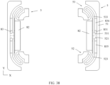
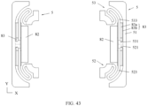
- the flexible printed circuit board includes a body, a first stub, and a second stub.
- the body is fixedly connected to the second face of the frame.
- the first stub includes a head end, a tail end, and a connection section connected between the head end and the tail end.
- the second stub includes a head end, a tail end, and a connection section connected between the head end and the tail end.
- the head end of the first stub and the head end of the second stub are both connected to a middle part of the body.
- the tail end of the first stub is fixedly connected to a corner of the voice coil, and the tail end of the second stub is fixedly connected to another corner of the voice coil.
- the head end of the first stub and the head end of the second stub are disposed directly opposite to the second side magnet.
- the first stub and the second stub are spaced from the second side magnet and the first side magnet.
- the tail end of the first stub and the tail end of the second stub vibrate with the voice coil, amplitudes gradually decrease from the tail end of the first stub to the connection section of the first stub to the head end of the first stub, amplitudes gradually decrease from the tail end of the second stub to the connection section of the second stub to the head end of the second stub, and amplitudes of the head end of the first stub and the head end of the second stub are quite small.
- the second side magnet directly faces the head end of the first stub and the head end of the second stub, so that the second side magnet can have a comparatively large height or a comparatively large local height, to improve magnetic induction strength of the magnetic circuit of the electroacoustic transducer.
- a part of the connection section of the first stub and that is close to the head end may be disposed directly opposite to the second side magnet, and a part of the connection section of the second stub and that is close to the head end may be disposed directly opposite to the second side magnet.
- the middle part of the body may also be disposed directly opposite to the second side magnet.
- the second side magnet is disposed directly opposite to the head end of the first stub, the head end of the second stub, and the middle part of the body. Therefore, the second side magnet can fully utilize a space under the flexible printed circuit board in the length direction of the electroacoustic transducer, so that the second side magnet has a comparatively large size, to effectively improve magnetic induction strength of the magnetic circuit.
- the second side magnet directly faces the head end of the first stub with a comparatively small amplitude, a part of the connection section that is close to the head end of the first stub, the head end of the second stub, and a part of the connection section that is close to the head end of the second stub. Therefore, the second side magnet can fully utilize a space under the flexible printed circuit board in the width direction of the electroacoustic transducer, so that the second side magnet has a comparatively large size, to effectively improve magnetic induction strength of the magnetic circuit.
- the head end of the first stub is connected to the head end of the second stub, and then the two connected head ends are connected to the middle part of the body.
- the head end of the first stub and the head end of the second stub each are connected to a different location in the middle part of the body, and a gap is formed between the two head ends.
- the first stub and the second stub of the flexible printed circuit board are symmetrically disposed.
- two locations at which the voice coil is connected to the flexible printed circuit board are subject to comparatively uniform stress, thereby facilitating steady vibration of the voice coil.
- the first stub includes a bent section and a straight section.
- One end of the bent section is connected to the tail end of the first stub, the other end of the bent section is connected to one end of the straight section, and the other end of the straight section is connected to the head end of the first stub.
- the bent section includes one or more arc sections, and each arc section is convex in a direction away from the center magnet.
- the arc section of the bent section is convex in the direction away from the center magnet, when the voice coil drives the flexible printed circuit board to vibrate, a shape of the flexible printed circuit board can better adapt to deformation and displacement requirements, so that the flexible printed circuit board has higher reliability and a longer service life.
- the bent section can further fully utilize a space on an outer side of a corner of the voice coil, to route a longer wire, so that when the flexible printed circuit board vibrates with the voice coil at a large amplitude, stress is comparatively small, and the flexible printed circuit board has higher reliability.
- an end part, arranged close to the bent part, of the body may have a comparatively large area, and the end part of the body not only has a sufficient area for fixing with an auxiliary vibration diaphragm (for details, refer to the following descriptions), but also has a sufficient area for fixing with an external structure of the electroacoustic transducer.
- the voice coil is in a rounded rectangular shape
- the tail end of the first stub is fixedly connected to a round corner of the voice coil
- each arc section is disposed coaxially with the round corner, connected to the first stub, of the voice coil.
- a shape of the flexible printed circuit board can better adapt to deformation and displacement requirements, so that the flexible printed circuit board has higher reliability and a longer service life.
- An extension direction of the straight section of the first stub may be roughly parallel to the width direction of the electroacoustic transducer.
- the straight section is comparatively long, so that the flexible printed circuit board is comparatively long, and a large amplitude is more easily implemented.
- the straight section occupies a comparatively small space in the length direction of the electroacoustic transducer, thereby helping suppress spatial extrusion against the magnetic circuit by the flexible printed circuit board, so that the magnetic circuit has a larger arrangement space, to ensure magnetic induction strength and sensitivity of the electroacoustic transducer.
- the bent section of the first stub further includes a plurality of transition sections, and the transition section may be arranged between adjacent arc sections, or may be arranged between the arc section and the straight section, or may be arranged between the arc section and the tail end of the first stub.
- the electroacoustic transducer further includes four auxiliary vibration diaphragms.
- the four auxiliary vibration diaphragms are arranged at intervals on sides, away from the voice coil, of the two flexible printed circuit boards.
- One end of each of the four auxiliary vibration diaphragms is fixedly connected to each of tail ends of first stubs of the two flexible printed circuit boards and tail ends of second stubs of the two flexible printed circuit boards, and the other end of the auxiliary vibration diaphragm is fixedly connected to an end of a body of an adjacent flexible printed circuit board. Two ends of each auxiliary vibration diaphragm can move relative to each other.
- the electroacoustic transducer includes two compliant systems, the voice diaphragm is a first compliant system located above the voice coil, and the flexible printed circuit board and the auxiliary vibration diaphragm are a second compliant system located under the voice coil.
- the two compliant systems vibrate with the voice coil, to suppress rolling vibration of the voice coil, and ensure comparatively good sound quality of the electroacoustic transducer.
- the auxiliary vibration diaphragm is roughly in a fan shape.
- the auxiliary vibration diaphragm includes a first fixed part, a vibrating part, and a second fixed part that are connected in sequence.
- the first fixed part is located on an inner side of the vibrating part, and the second fixed part is located on an outer side of the vibrating part.
- the first fixed part is fixedly connected to a tail end of a stub of the flexible printed circuit board, and the second fixed part is fixedly connected to an end of the body of the flexible printed circuit board.
- a cross-sectional shape of the vibrating part of the auxiliary vibration diaphragm is an arc or approximately arc shape, and an extension track of the vibrating part is in an arc shape.
- the vibrating part of the auxiliary vibration diaphragm is concave.
- the vibrating part is concave in a direction away from a top face of the first fixed part and a top face of the second fixed part.
- the first fixed part of the auxiliary vibration diaphragm is in a fan shape.
- a notch is formed on a side, away from the first fixed part, of the second fixed part of the auxiliary vibration diaphragm.
- a part of the flexible printed circuit board is exposed at an end at which the auxiliary vibration diaphragm is fixed to the flexible printed circuit board.
- an end part of the body of the flexible printed circuit board may be exposed through the notch of the second fixed part of the auxiliary vibration diaphragm.
- An exposed region of the end part of the body of the flexible printed circuit board relative to the auxiliary vibration diaphragm may be used for connecting another component of the electroacoustic transducer.
- the extension track of the vibrating part of the auxiliary vibration diaphragm is disposed coaxially with a round corner, connected to the auxiliary vibration diaphragm, of the voice coil.
- a shape of the vibrating part of the auxiliary vibration diaphragm can better adapt to deformation and displacement requirements, so that the auxiliary vibration diaphragm has higher reliability and a longer service life.
- an arc section of a bent section of the stub of the flexible printed circuit board is also disposed coaxially with the round corner of the voice coil, so that a risk of collision between the bent section and the vibrating part can be reduced, and the electroacoustic transducer has higher reliability.
- a height of the first side magnet is greater than a height of the second side magnet.
- the thickness direction of the center magnet is parallel to the thickness direction of the electroacoustic transducer.
- the height of the first side magnet may be greater than the height of the second side magnet, to fully utilize a space and improve magnetic induction strength of the magnetic circuit, so that the electroacoustic transducer has comparatively high sensitivity.
- the height of the first side magnet in the thickness direction of the electroacoustic transducer, may be greater than a sum of the height of the second side magnet, a height of the flexible printed circuit board, and a spacing between the second side magnet and the flexible printed circuit board.
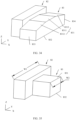
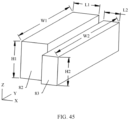
- the second side magnet includes a first surface and a second surface that are disposed opposite to each other, and the first surface faces the flexible printed circuit board.
- the first surface includes a first plane, a first inclined plane, and a second inclined plane.
- the first plane is parallel to the second surface.
- One end of the first inclined plane is connected to one end of the first plane, the other end of the first inclined plane extends in a direction toward the second surface, one end of the second inclined plane is connected to the other end of the first plane, and the other end of the second inclined plane extends in a direction toward the second surface.
- the second side magnet has a structure in which the middle is high and heights on two sides gradually decrease.
- a location in the middle that is high may directly face a part, with a small amplitude, of the flexible printed circuit board.
- a location on the two sides on which the heights gradually decrease may directly face a part, with a gradually increasing amplitude, of the flexible printed circuit board. Therefore, an abundant vibration space can be reserved for the flexible printed circuit board, and further, a non-interfering height can be fully utilized, and a magnet size can be increased, so that the electroacoustic transducer has higher magnetic induction strength.
- a size of the second side magnet in the width direction of the electroacoustic transducer may range from 2 millimeters to 10 millimeters.
- the first plane directly faces the head end of the first stub and the head end of the second stub.
- the first plane may directly face another part, with a comparatively small amplitude, of the flexible printed circuit board, for example, the part that is of the connection section of the first stub and that is close to the head end, and the part that is of the connection section of the second stub and that is close to the head end.
- the second side magnet has a larger volume, and magnetic induction strength of the electroacoustic transducer can be improved.
- the second inclined plane and the first inclined plane may be symmetrically disposed, and the symmetrical planes are perpendicular to the second surface. Because the first stub and the second stub of the flexible printed circuit board are symmetrically disposed, and vibration amplitudes of the first stub and the second stub are symmetrical, the second inclined plane and the first inclined plane that are symmetrically disposed can better match vibration statuses of the first stub and the second stub.
- the first side magnet and the second side magnet are designed in a separated manner, and may be fixed to each other by bonding adjacent surfaces. Because the second side magnet and the first side magnet have different shapes on a YZ plane (that is, a plane on which the width direction and the thickness direction of the electroacoustic transducer are located), the second side magnet and the first side magnet are separately molded and then assembled to form an integrated structure, so that costs can be reduced, and costs of the electroacoustic transducer are lower.
- a YZ plane that is, a plane on which the width direction and the thickness direction of the electroacoustic transducer are located
- the first side magnet and the second side magnet may be alternatively an integrated irregularly-shaped magnet.
- the second side magnet, the first side magnet, and the center magnet are arranged in a first direction.
- a size of the first side magnet in a second direction is a first width.
- the second direction is perpendicular to the first direction and the thickness direction of the center magnet.
- a size of the second side magnet in the second direction is a second width. The second width is less than the first width.
- a width of the second side magnet in the width direction of the electroacoustic transducer is comparatively small, and the second side magnet directly faces a part, with a small amplitude, of the flexible printed circuit board, for example, the head end of the first stub and the head end of the second stub.
- Spaces on two sides of the second side magnet in the width direction of the electroacoustic transducer may be used as vibration spaces for the flexible printed circuit board, and directly face a part, with a comparatively large amplitude, of the flexible printed circuit board, for example, the connection section of the first stub and the connection section of the second stub.
- the second side magnet may directly face another part, with a comparatively small amplitude, of the flexible printed circuit board, for example, the part that is of the connection section of the first stub and that is close to the head end, and the part that is of the connection section of the second stub and that is close to the head end, to have a larger volume.
- the second width of the second side magnet when vibration space requirements of the first stub and the second stub are met, the second width of the second side magnet may be appropriately increased, or a height of the second side magnet may be reduced and the second width of the second side magnet may be greatly increased (in this case, the second width may be greater than or equal to the first width of the first side magnet), so that the second side magnet has a larger volume.
- the first surface of the second side magnet is parallel to the second surface.
- the first surface directly faces the head end of the first stub of the flexible printed circuit board and the head end of the second stub of the flexible printed circuit board.
- the second side magnet further includes a first side face and a second side face.
- the first side face connects one end of the first surface to one end of the second surface.
- the second side face connects the other end of the first surface to the other end of the second surface.
- the first side face directly faces the connection section of the first stub.
- the second side face directly faces the connection section of the second stub.
- the second side magnet fully utilizes a space under the flexible printed circuit board, so that the electroacoustic transducer has higher magnetic induction strength.
- the first side magnet and the second side magnet are integrated, thereby helping simplify an assembly process of the electroacoustic transducer and improve assembly precision.
- the second side magnet, the first side magnet, and the center magnet are arranged in a first direction.
- a cross-sectional shape of the first side magnet is the same as a cross-sectional shape of the second side magnet.
- a cross section of the first side magnet and a cross section of the second side magnet are both perpendicular to the first direction.
- the cross section of the second side magnet may be in an irregular shape, to have a comparatively large area while a vibration space is reserved for the flexible printed circuit board, so that volumes of the second side magnet and the first side magnet are comparatively large.
- the second side magnet, the first side magnet, and the center magnet are arranged in a first direction.
- a height of the first side magnet is the same as a height of the second side magnet.
- a size of the first side magnet in a second direction is a first width.
- the second direction is perpendicular to the first direction and the thickness direction of the center magnet.
- a size of the second side magnet in the second direction is a second width.
- the second width is less than the first width.
- shapes of the second side magnet and the first side magnet may be comparatively regular cuboids, to reduce processing difficulty and costs.
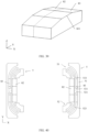
- the second side magnet includes a first magnetic part and a second magnetic part.
- the first magnetic part is located between the second magnetic part and the first side magnet.
- the second magnetic part is disposed directly opposite to the body of the flexible printed circuit board.
- the first magnetic part is disposed directly opposite to the head end of the first stub of the flexible printed circuit board and the head end of the second stub of the flexible printed circuit board.
- the first magnetic part may be disposed directly opposite to the part that is of the connection section of the first stub and that is close to the head end, and the part that is of the connection section of the second stub and that is close to the head end.
- a length of the first magnetic part in the length direction of the electroacoustic transducer is less than that of the second side magnet in the foregoing embodiment.
- a height of the second magnetic part is greater than a height of the first magnetic part, and the height of the second magnetic part is less than the height of the first side magnet.
- a top face of the second magnetic part may be in contact with the body of the flexible printed circuit board, to fully utilize a space under the flexible printed circuit board.
- the first magnetic part and the second magnetic part may be integrated, or may be assembled (for example, bonded) to form an integrated structure.
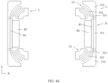
- the flexible printed circuit board includes a body, a first stub, and a second stub.
- the body is fixedly connected to the second face of the frame.
- a head end of the first stub and a head end of the second stub are respectively connected to two end parts of the body.
- a tail end of the first stub is fixedly connected to a corner of the voice coil, and a tail end of the second stub is fixedly connected to another corner of the voice coil.
- the first stub and the second stub of the flexible printed circuit board are connected to the two end parts of the body, a space on an inner side of a middle part of the body is released.
- a length of the second side magnet is reduced, and a length of the first side magnet is increased, so that the magnetic circuit has higher magnetic induction strength.
- the length of the first side magnet may be greater than the length of the second side magnet.
- a height of the first side magnet is greater than a height of the second side magnet.
- the thickness direction of the center magnet is parallel to the thickness direction of the electroacoustic transducer.
- the height of the first side magnet may be greater than the height of the second side magnet, to fully utilize a space and improve magnetic induction strength of the magnetic circuit, so that the electroacoustic transducer has comparatively high sensitivity.
- the first side magnet is in a cuboid shape
- the second side magnet is in a cuboid shape.
- the height of the first side magnet may be greater than the height of the second side magnet.
- a width of the second side magnet may be greater than a width of the first side magnet.
- the basin stand further includes a plurality of legs.
- the plurality of legs are fixed to the second face of the frame at intervals.
- the electroacoustic transducer further includes a lower electrode plate.
- the lower electrode plate is fixedly connected to the plurality of legs and is spaced from the frame.
- the center magnet, the two first side magnets, and the two second side magnets are all fixed to a side, facing the frame, of the lower electrode plate.
- the electroacoustic transducer is supported between the frame and the lower electrode plate by the plurality of legs, and the plurality of legs can play a supporting and connecting role while occupying a quite small space between the frame and the lower electrode plate, so that a comparatively large magnetic circuit arrangement space is formed between the frame and the lower electrode plate, and the space can be fully utilized for the magnetic circuit to arrange magnets, thereby achieving comparatively high magnetic induction strength and comparatively high sensitivity of the electroacoustic transducer.
- the lower electrode plate can not only serve as a magnetic conductive piece to seal a magnetic field to reduce adverse impact of the magnetic field of the electroacoustic transducer on a surrounding environment, but also serve as a carrier to fix the center magnet, the two first side magnets, and the two second side magnets, so that a relative location relationship between the plurality of magnets is stable and reliable, and the electroacoustic transducer has comparatively high reliability.
- the electroacoustic transducer further includes a center electrode plate and a side electrode plate.
- the center electrode plate is fixed to a side, away from the lower electrode plate, of the center magnet.
- the side electrode plate is fixed to the inner side of the frame, and is spaced from the flexible printed circuit board.
- the side electrode plate includes a first electrode plate part.
- the first electrode plate part is disposed directly opposite to the first side magnet and the second side magnet.
- a second gap is formed between the first electrode plate part and the center electrode plate. The second gap is connected to the first gap.
- the voice coil is partially located in the second gap.
- the body of the flexible printed circuit board and the side electrode plate may be stacked at intervals in the thickness direction of the electroacoustic transducer, and the body of the flexible printed circuit board and the side electrode plate that are fixed to the basin stand are separated by some structures of the basin stand.
- a fixing groove is formed on the inner side of the frame, and the fixing groove is provided around the space on the inner side of the frame.
- An opening of the fixing groove is located on an inner side face of the frame, and the fixing groove is concave in a direction toward an outer side face.
- a connection frame part of the side electrode plate may be clamped into the fixing groove of the frame.
- the connection frame part is partially located in the fixing groove and partially located outside the fixing groove.
- the first electrode plate part and a second electrode plate part of the side electrode plate are located outside the fixing groove.
- the first electrode plate part is roughly in a T shape
- the first electrode plate part includes a first part and a second part
- the second part connects the first part to the connection frame part.
- Avoidance gaps are formed on two sides of the second part of the first electrode plate part, and the avoidance gaps are located between the first part of the first electrode plate part and the connection frame part.
- Four corners on an inner side of the connection frame part form corner gaps. The corner gaps connect adjacent avoidance gaps.
- the first part of the first electrode plate part is disposed directly opposite to the first side magnet.
- the second part of the first electrode plate part is disposed directly opposite to the second side magnet.
- a straight-side part, connected to the second part of the first electrode plate part, of the connection frame part of the side electrode plate is disposed directly opposite to the second side magnet.
- the first part of the first electrode plate part may be fixed to the first side magnet through bonding.
- a gap is formed between the second side magnet, and the second part of the first electrode plate part and the connection frame part.
- a second gap is formed between the first electrode plate part and the center electrode plate. The second gap is connected to the first gap.
- the head end of the first stub of the flexible printed circuit board directly faces the second part of the first electrode plate part of the side electrode plate.
- the head end of the first stub and the second part of the first electrode plate part are spaced from each other in the thickness direction of the electroacoustic transducer.
- the connection section and the tail end of the first stub directly face an avoidance gap and a corner gap on one side of the second part of the first electrode plate part.
- the head end of the second stub of the flexible printed circuit board directly faces the second part of the first electrode plate part of the side electrode plate.
- the head end of the second stub and the second part of the first electrode plate part are spaced from each other in the thickness direction of the electroacoustic transducer.
- the connection section and the tail end of the second stub directly face an avoidance gap and a corner gap on the other side of the second part of the first electrode plate part.
- the electroacoustic transducer further includes two third side magnets.
- the two third side magnets are fixed to a side, facing the frame, of the lower electrode plate, and are symmetrically arranged on the other two sides of the center magnet.
- a third gap is formed between the third side magnet and the center magnet.
- the side electrode plate further includes a second electrode plate part. The second electrode plate part directly faces the third side magnet.
- a fourth gap is formed between the second electrode plate part and the center electrode plate. The fourth gap is connected to the third gap.
- the voice coil is partially located in the fourth gap and partially located in the third gap.
- the third side magnet is spaced from the flexible printed circuit board.
- each of two ends of the third side magnet is close to a tail end of a stub of the flexible printed circuit board.
- An end face of each of the two ends of the third side magnet is partially concave to form an avoidance region.
- the avoidance region is connected to the third gap.
- the tail end of the stub of the flexible printed circuit board is partially located in the avoidance region, and forms a gap with a wall surface of the avoidance region.
- a straight-side part, connected to the second electrode plate part, of the connection frame part of the side electrode plate is disposed directly opposite to the third side magnet.
- the third side magnet fully utilizes a space between the side electrode plate and the lower electrode plate, to have a larger size in the width direction of the electroacoustic transducer, so that the magnetic circuit has higher magnetic induction strength.
- the electroacoustic transducer further includes a connection frame.
- the connection frame is located between the voice coil and the voice diaphragm. One end of the connection frame is fixedly connected to the voice coil, and the other end of the connection frame is fixedly connected to the voice diaphragm.
- connection frame separates the voice coil from the voice diaphragm, so that the voice diaphragm is away from the voice coil.
- connection frame may perform heat dissipation for the voice coil, thereby reducing a risk of damaging the voice diaphragm due to overheating of the voice coil.
- the voice coil is connected to the voice diaphragm through the connection frame. Therefore, a spacing between the voice diaphragm and an end part, away from the voice diaphragm, of the voice coil is comparatively large, so that the voice coil can be fully inserted in the magnetic circuit, and a magnetic field generated by the magnetic circuit effectively acts on the voice coil.
- a spacing between the voice diaphragm and the magnetic circuit is comparatively large, and a vibration space for the voice diaphragm is comparatively large, thereby helping the voice diaphragm implement large-amplitude vibration.
- a cross-sectional shape of the connection frame is roughly a Z shape, and an extension track of the connection frame is in a rounded rectangular shape.
- the connection frame includes a main part, an outer extension part, and an inner extension part.
- the outer extension part is connected to a bottom face of the main part and extends toward an outer side of the main part.
- An area of a bottom face of the outer extension part is larger than an area of the bottom face of the main part, to increase a connection area between the connection frame and other components.
- the inner extension part is connected to a top face of the main part and extends toward an inner side of the main part.
- An area of a top face of the inner extension part is greater than an area of the top face of the main part, to increase a connection area between the connection frame and other components.
- connection frame may be integrated.
- the cross-sectional shape of the connection frame may be alternatively a vertical bar shape, an L shape, an inverted L shape, a T shape, an inverted T shape, a " " shape, or the like.
- an embodiment of this application further provides a speaker module.
- the speaker module includes an upper module housing and the electroacoustic transducer according to any one of the foregoing implementations.
- the electroacoustic transducer serves as a speaker core of the speaker module.
- the electroacoustic transducer is fixedly connected to the upper module housing, and a front speaker box is formed between a voice diaphragm and the upper module housing.
- the upper module housing is provided with a sound outlet hole. The sound outlet hole connects the front speaker box to an outer side of the speaker module.
- the electroacoustic transducer has comparatively high magnetic field strength and comparatively high sensitivity, so that the speaker module has a larger sound volume, to have a wider application scope.
- the speaker module further includes a lower module housing.
- the lower module housing is fixed to the upper module housing.
- the electroacoustic transducer is located inside the lower module housing and the upper module housing.
- a rear speaker box is formed on a side, away from the front speaker box, of the voice diaphragm.
- the lower module housing is provided with a leakage hole. The leakage hole connects the rear speaker box to the outer side of the speaker module.
- the speaker module forms a modular structure through sealing by the lower module housing and the upper module housing.
- the lower module housing and the upper module housing can not only fully protect the electroacoustic transducer located inside the lower module housing and the upper module housing, but also help simplify an assembly structure for the speaker module and other components.
- the speaker module further includes a buffer piece.
- the buffer piece is fixed between the lower module housing and the electroacoustic transducer, so that the electroacoustic transducer is firmly connected to the upper module housing, thereby avoiding a risk of shaking of the electroacoustic transducer, and improving reliability of the speaker module.
- an embodiment of this application further provides an electronic device.
- the electronic device includes a housing and the speaker module according to any one of the foregoing implementations.
- the speaker module is accommodated in the housing.
- the housing is provided with a speaker hole.
- the speaker hole connects a sound outlet hole to an outer side of the electronic device.
- the speaker module can produce a comparatively large sound volume, so that sound play performance of the electronic device is better, thereby helping improve user experience.
- an embodiment of this application further provides an electronic device.
- the electronic device includes a housing, a display module, and a receiver.
- the display module includes a cover plate and a display panel.
- the cover plate is fixed to the housing.
- the display panel is fixed to an inner surface, facing the housing, of the cover plate.
- the receiver is accommodated in the housing, and the receiver is the electroacoustic transducer according to any one of the foregoing implementations.
- the cover plate is provided with a receiver hole, or a receiver hole is formed between an edge of the cover plate and the housing, or the housing is provided with a receiver hole. Sound output by the receiver is transmitted to an outer side of the electronic device through the receiver hole.
- the electroacoustic transducer has comparatively high magnetic field strength and comparatively high sensitivity. Therefore, an earpiece using the electroacoustic transducer can produce a comparatively large sound volume, so that sound play performance of the electronic device is better, thereby helping improve user experience.
- An embodiment of this application provides an electroacoustic transducer.
- the electroacoustic transducer is configured to convert an electrical signal into a sound signal.
- structures of a magnetic circuit assembly and a flexible printed circuit board are optimized to ensure a driving force for the magnetic circuit assembly, so that the electroacoustic transducer has comparatively high sensitivity.
- An embodiment of this application further provides an electronic device including the electroacoustic transducer.
- the electronic device may be a product with a sound play function, for example, a mobile phone, a tablet computer, a notebook computer, a wearable device, or a personal stereo.
- the wearable device may be a smart band, a smart watch, a smart head-mounted display, smart glasses, or the like.
- the electroacoustic transducer may be used for the electronic device as a speaker core of a speaker module (also referred to as a loudspeaker), or may be used for the electronic device as a receiver (also referred to as an earpiece).
- a speaker module also referred to as a loudspeaker
- a receiver also referred to as an earpiece
- FIG. 1 is a schematic structural diagram of an electronic device 1000 according to an embodiment of this application.
- the electronic device 1000 shown in FIG. 1 is described by using a mobile phone as an example.
- the electronic device 1000 includes a housing 100, a display module 200, a receiver 300, a camera module 500, a speaker module 600, a first circuit board 700, a second circuit board 800, and a battery 900.
- the housing 100 includes a frame 1001 and a back housing 1002.
- the frame 1001 is connected to a periphery of the back housing 1002.
- the frame 1001 and the back housing 1002 may be of an integrated structure, or may be assembled to form an integrated structure.
- the housing 100 is provided with a speaker hole 1003.
- the speaker hole 1003 connects an inner side of the electronic device 1000 to an outer side of the electronic device 1000.
- the display module 200 includes a cover plate 2001 and a display panel 2002.
- the cover plate 2001 is fixed to the housing 100.
- the cover plate 2001 is fixed to a side, away from the back housing 1002, of the frame 1001.
- the display panel 2002 is fixed to an inner surface, facing the back housing 1002, of the cover plate 2001.
- the cover plate 2001 is configured to protect the display panel 2002.
- the display panel 2002 is configured to display an image, and the display panel 2002 may be further integrated with a touch function.
- the cover plate 2001 is provided with a light transmission part 2003 and a receiver hole 2004.
- the light transmission part 2003 is a region allowing light to pass.
- an ink layer of the cover plate 2001 is hollowed out in the light transmission part 2003.
- the receiver hole 2004 is a through-hole penetrating the cover plate 2001.
- a projection of the display panel 2002 on the cover plate 2001, the light transmission part 2003, and the receiver hole 2004 are staggered.
- a receiver hole is formed between an edge of the cover plate 2001 and the housing 100.
- a receiver hole is formed between an edge, at the top of the electronic device 1000, of the cover plate 2001 and an edge, at the top of the electronic device 1000, of the frame 1001 of the housing 100.
- the housing 100 is provided with a receiver hole.
- a receiver hole is formed in a region, at the top of the electronic device 1000, of the frame 1001 of the housing 100. A specific formation structure and location of the receiver hole are not strictly limited in this application.
- the receiver 300 is accommodated in the housing 100.
- the receiver 300 is located between the display module 200 and the back housing 1002. Sound output by the receiver 300 is transmitted to the outer side of the electronic device 1000 through the receiver hole 2004, to implement a sound play function of the electronic device 1000.
- the receiver 300 may be an electroacoustic transducer described in the following embodiments. In another embodiment, the receiver 300 may be alternatively an electroacoustic transducer with another structure.
- the camera module 500 is accommodated in the housing 100.
- the camera module 500 is located between the display module 200 and the back housing 1002.
- the camera module 500 collects light through the light transmission part 2003 of the cover plate 2001, to perform photographing.
- the electronic device 1000 may further include another camera module accommodated in the housing 100.
- a photographing through-hole may be provided on the back housing 1002.
- the another camera module may collect light through the photographing through-hole, to perform photographing.
- the speaker module 600 is accommodated in the housing 100.
- the speaker module 600 is located between the display module 200 and the back housing 1002. Sound output by the speaker module 600 can be transmitted to the outer side of the electronic device 1000 through the speaker hole 1003, to implement the sound play function of the electronic device 1000.
- the speaker module 600 includes a speaker core.
- the speaker core may be the electroacoustic transducer described in the following embodiments. In another embodiment, the speaker core may be alternatively an electroacoustic transducer with another structure.
- the first circuit board 700, the second circuit board 800, and the battery 900 are all accommodated in the housing 100.
- the first circuit board 700 and the second circuit board 800 are respectively located on two sides of the battery 900.
- the first circuit board 700 is located at the top of the electronic device 1000
- the battery 900 is located in the middle of the electronic device 1000
- the second circuit board 800 is located at the bottom of the electronic device 1000.
- a plurality of devices may be fixed to the first circuit board 700 and the second circuit board 800.
- the devices include but are not limited to a processor, a memory, and the like.
- Functional modules of the electronic device 1000 for example, the display module 200, the camera module 500, the speaker module 600, and the receiver 300, are coupled to the processor.
- the first circuit board 700 and the second circuit board 800 may be connected by using a wire such as a flexible printed circuit board or a coaxial line, to implement an electrical connection between the first circuit board 700 and the second circuit board 800.
- the battery 900 is configured to supply power to the electronic device 1000.
- the first circuit board 700 or the second circuit board 800 may be alternatively omitted from the electronic device 1000, and a device that needs to be fixed to a circuit board may be fixed to a retained circuit board.
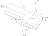
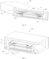
- FIG. 2 is a schematic structural diagram of the speaker module 600 of the electronic device 1000 shown in FIG. 1 .
- the speaker module 600 includes an electroacoustic transducer 10, an upper module housing 20, a lower module housing 30, and a circuit board 40.
- the upper module housing 20 and the lower module housing 30 are fixed to each other to form a sound box.
- the electroacoustic transducer 10 is located inside the sound box.
- One end of the circuit board 40 is located inside the sound box, to connect to the electroacoustic transducer 10.
- the other end of the circuit board 40 is located outside the sound box, to electrically connect the electroacoustic transducer 10 to an external device of the speaker module 600.
- the end of the circuit board 40 that is located outside the sound box may be fixed and electrically connected to the second circuit board 800.
- the upper module housing 20 is provided with a sound outlet hole 201, and the sound outlet hole 201 connects an inner side of the sound box to an outer side of the sound box. Sound output by the electroacoustic transducer 10 can be transmitted to the outer side of the sound box through the sound outlet hole 201.
- the speaker hole 1003 of the housing 100 connects the sound outlet hole 201 of the electroacoustic transducer 10 to the outer side of the electronic device 1000. The sound output by the electroacoustic transducer 10 can be transmitted to the outer side of the electronic device 1000 through the sound outlet hole 201 and the speaker hole 1003.
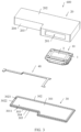
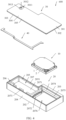
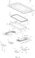
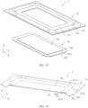
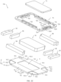
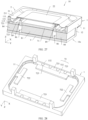
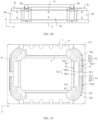
- FIG. 3 is a schematic exploded view of the speaker module 600 shown in FIG. 2
- FIG. 4 is a schematic structural diagram of the speaker module 600 shown in FIG. 3 from another angle.
- the upper module housing 20 includes a top face 202 and a bottom face 203 that are disposed opposite to each other, and a peripheral side face 204 connected between the top face 202 and the bottom face 203.
- An opening of the sound outlet hole 201 is provided on the peripheral side face 204 of the upper module housing 20.
- the upper module housing 20 further includes a positioning groove 205, a first notch 206, and an accommodation groove 207.
- An opening of the positioning groove 205 is provided on the bottom face 203 of the upper module housing 20.
- the first notch 206 penetrates a side wall of the positioning groove 205 until the peripheral side face 204 of the upper module housing 20, and extends to the bottom face 203 of the upper module housing 20.
- An opening of the accommodation groove 207 is provided on a bottom wall 2051 of the positioning groove 205.
- a first protrusion 2072 and a second protrusion 2073 protrude from a bottom wall 2071 of the accommodation groove 207.
- the first protrusion 2072 may be arranged roughly in a U shape to form an enclosed region 2076, and the enclosed region 2076 is connected to the sound outlet hole 201.
- a third protrusion 2075 protrudes from a side wall 2074 of the accommodation groove 207, and the third protrusion 2075 is connected to two ends of the first protrusion 2072.
- the second protrusion 2073 may include a continuous unbroken protrusion strip, or may include a plurality of broken protrusion strips.
- orientation terms such as “top” and “bottom” used for the speaker module 600 in this embodiment of this application are mainly intended for description based on a display orientation of the speaker module 600 in FIG. 3 , and do not limit an orientation of the speaker module 600 in an actual application scenario.
- the electroacoustic transducer 10 includes a basin stand 1 and a voice diaphragm 2 fixed to the basin stand 1.
- the electroacoustic transducer 10 outputs sound through vibration of the voice diaphragm 2.
- the circuit board 40 may be a flexible printed circuit board. One end of the circuit board 40 includes two branches, and connection ends can be formed at tail ends of the two branches.
- the lower module housing 30 includes a substrate 301 and a limiting protrusion strip 302.
- the substrate 301 includes a top face 303 and a bottom face 304 that are disposed opposite to each other, and a peripheral side face 305 connected between the top face 303 and the bottom face 304.
- the limiting protrusion strip 302 is fixed to the top face 303 of the substrate 301, and is disposed around a periphery of the top face 303 of the substrate 301.
- a second notch 3021 may be provided on the limiting protrusion strip 302.
- the second notch 3021 is concave in a direction from a top face 3022 of the limiting protrusion strip 302 toward the top face 303 of the substrate 301, and connects a space on an inner side of the limiting protrusion strip 302 to a space on an outer side of the limiting protrusion strip 302.
- the second notch 3021 directly faces the first notch 206, to form a notch with a comparatively large diameter.
- the second notch 3021 may be alternatively omitted from the lower module housing 30.
- the substrate 301 is provided with a connection groove 3011 and a leakage hole 3012.
- An opening of the connection groove 3011 is provided on the bottom face 304 of the substrate 301, and extends to the peripheral side face 305 of the substrate 301. Openings at two ends of the leakage hole 3012 are respectively provided on a bottom wall 3013 of the connection groove 3011 and the top face 303 of the substrate 301.
- the leakage hole 3012 connects a space at the top of the substrate 301, spaces at the bottom of the connection groove 3011 and the substrate 301, and a peripheral space of the substrate 301.
- the leakage hole 3012 of the substrate 301 penetrates the bottom face 304 of the substrate 301 until the top face 303 of the substrate 301, and the substrate 301 is not provided with the connection groove 3011.
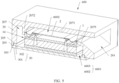
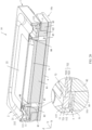
- FIG. 5 is a schematic structural diagram of the speaker module 600 shown in FIG. 2 that is cut along A-A
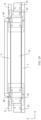
- FIG. 6 is a schematic structural diagram of the speaker module 600 shown in FIG. 2 that is cut along B-B.
- cutting along A-A means cutting along a plane on which a line A-A and arrows at two ends of the line A-A are located
- cutting along B-B means cutting along a plane on which a line B-B and arrows at two ends of the line B-B are located.
- the lower module housing 30 is buckled to the upper module housing 20.
- the top face 303 of the substrate 301 of the lower module housing 30 is in contact with the bottom face 203 of the upper module housing 20.
- the limiting protrusion strip 302 of the lower module housing 30 is clamped into the positioning groove 205 of the upper module housing 20, and a concave-convex fit structure is formed between the limiting protrusion strip 302 and the positioning groove 205, so that the lower module housing 30 and the upper module housing 20 are fixed to each other.
- the lower module housing 30 and the upper module housing 20 jointly encircle a speaker box space 6001.
- the electroacoustic transducer 10 is accommodated in the speaker box space 6001.
- the electroacoustic transducer 10 is located inside the lower module housing 30 and the upper module housing 20.
- the upper module housing 20 is fixedly connected to the basin stand 1 of the electroacoustic transducer 10.
- the basin stand 1 is partially clamped into the enclosed region 2076 (as shown in FIG. 4 ), and the first protrusion 2072 and the third protrusion 2075 continuously abut against a periphery of the basin stand 1.
- the voice diaphragm 2 of the electroacoustic transducer 10 is located in the enclosed region 2076.
- the voice diaphragm 2 divides the speaker box space 6001 into a front speaker box 6002 and a rear speaker box 6003.
- the front speaker box 6002 is formed between the upper module housing 20 and the voice diaphragm 2.
- the bottom wall 2071 of the accommodation groove 207 of the upper module housing 20, the first protrusion 2072, the voice diaphragm 2, and the third protrusion 2075 jointly encircle the front speaker box 6002.
- the sound outlet hole 201 connects the front speaker box 6002 to an outer side of the speaker module 600.
- the rear speaker box 6003 is located on a side, away from the front speaker box 6002, of the voice diaphragm 2.
- the rear speaker box 6003 is connected to the outer side of the speaker module 600 through the leakage hole 3012 and the connection groove 3011.
- FIG. 7 is a schematic structural diagram of the speaker module 600 shown in FIG. 2 that is cut along A-A according to another embodiment.
- the speaker module 600 may further include a buffer piece 50.
- the buffer piece 50 is fixed to the top face 303 of the substrate 301 of the lower module housing 30.
- the buffer piece 50 is located on the inner side of the limiting protrusion strip 302. A side, away from the substrate 301, of the buffer piece 50 abuts against the electroacoustic transducer 10, so that the electroacoustic transducer 10 is firmly connected to the upper module housing 20, thereby avoiding a risk of shaking of the electroacoustic transducer 10, and improving reliability of the speaker module 600.
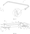
- FIG. 8 is a partial schematic structural diagram of the speaker module 600 shown in FIG. 2 .
- One end of the circuit board 40 is located inside the upper module housing 20, and the other end extends out of the upper module housing 20 through the first notch 206.
- a part of the circuit board 40 that is located inside the upper module housing 20 is disposed on the second protrusion 2073.
- the part of the circuit board 40 that is located inside the upper module housing 20 is fixedly connected (for example, bonded) to an end face of the second protrusion 2073.
- the circuit board 40 is firmly fixed to the upper module housing 20, so that a risk of damage due to shaking can be reduced.
- End parts of the two branches of the circuit board 40 are respectively fixed to two corners of the electroacoustic transducer 10, to electrically connect to the electroacoustic transducer 10.
- structures and shapes of the upper module housing 20, the lower module housing 30, and the circuit board 40 of the speaker module 600 may be alternatively designed into other solutions according to actual requirements (for example, a requirement for a mounting environment and a requirement for a use scenario) of the speaker module 600.
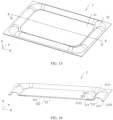
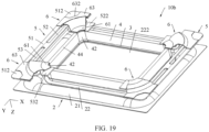
- FIG. 9 is a structural diagram of the electroacoustic transducer 10 shown in FIG. 3
- FIG. 10 is a partial schematic exploded view of the electroacoustic transducer 10 shown in FIG. 9 .
- an X direction is a length direction of the electroacoustic transducer 10
- a Y direction is a width direction of the electroacoustic transducer 10
- a Z direction is a thickness direction of the electroacoustic transducer 10.
- orientation terms such as “top” and “bottom” used for the electroacoustic transducer 10 in this embodiment of this application are mainly intended for description based on a display orientation of the electroacoustic transducer 10 in FIG. 9 , and do not limit an orientation of the electroacoustic transducer 10 in an actual application scenario.
- a plurality of components of the electroacoustic transducer 10 are symmetrically disposed. That two components are symmetrically disposed means that the two components are in an axially symmetrical relationship relative to a reference plane, and a slight deviation caused by a manufacturing tolerance, an assembly tolerance, or the like is allowed. Some components may be symmetrical relative to a first reference plane, some components may be symmetrical relative to a second reference plane, and the second reference plane intersects with the first reference plane. For example, as shown in FIG.
- the first reference plane may pass through a line K-K and be parallel to a YZ plane, where the YZ plane is a plane on which the width direction Y of the electroacoustic transducer 10 and the thickness direction Z of the electroacoustic transducer 10 are located;
- the second reference plane may pass through a line J-J and be parallel to an XZ plane, where the XZ plane is a plane on which the length direction X of the electroacoustic transducer 10 and the thickness direction Z of the electroacoustic transducer 10 are located.
- the electroacoustic transducer 10 includes a support assembly 10a, a vibration assembly 10b, and a magnetic circuit assembly 10c.
- the support assembly 10a includes the basin stand 1.
- the vibration assembly 10b and the magnetic circuit assembly 10c are mounted to the basin stand 1. A part, fixed to the basin stand 1, of each component of the vibration assembly 10b does not move relative to the basin stand 1, and a rest part may vibrate relative to the basin stand 1.
- the magnetic circuit assembly 10c is fixed relative to the basin stand 1, and the magnetic circuit assembly 10c is configured to provide a driving magnetic field for the vibration assembly 10b.
- FIG. 11 is a schematic structural diagram of the basin stand 1 shown in FIG. 10 that is cut along C-C.
- the basin stand 1 includes a frame 11 and a plurality of legs 12.
- the frame 11 is roughly a rectangular frame.
- the frame 11 includes a first face 111 and a second face 112 that are opposite to each other.
- the plurality of legs 12 are fixed to the second face 112 at intervals. In this embodiment of this application, that two components are spaced from each other or are disposed at intervals means that there is a gap between the two components.
- a quantity of the plurality of legs 12 may be 4, and the legs 12 are symmetrically fixed to two side edges of the frame 11.
- the plurality of legs 12 may be symmetrical relative to the first reference plane, or may be symmetrical relative to the second reference plane.
- the frame 11 further includes an inner side face 113 and an outer side face 114 that are disposed opposite to each other.
- the inner side face 113 and the outer side face 114 are connected between the first face 111 and the second face 112.
- the inner side face 113 is disposed obliquely relative to the outer side face 114, and a spacing between the inner side face 113 and the outer side face 114 decreases in a direction toward the first face 111, so that a space on an inner side of the frame 11 can form a shape that is narrow at the bottom and wide at the top.
- a fixing groove 115 is formed on the inner side of the frame 11, and the fixing groove 115 is provided around the space on the inner side of the frame 11.
- An opening of the fixing groove 115 is located on the inner side face 113 of the frame 11, and the fixing groove 115 is concave in a direction toward the outer side face 114.
- the basin stand 1 further includes two limiting blocks 13, and the two limiting blocks 13 are symmetrically fixed to inner sides of the two side edges of the frame 11.
- the two limiting blocks 13 are symmetrical relative to the second reference plane.
- the limiting block 13 includes a limiting strip 131 and at least one limiting leg 132.
- the limiting strip 131 is fixed to the inner side face 113 of the frame 11, and a bottom face of the limiting strip 131 is disposed in a coplanar manner with a side wall of the fixing groove 115.
- the at least one limiting leg 132 is fixed to the bottom face of the limiting strip 131 and extends into the fixing groove 115.
- the limiting strip 131 includes a side surface connecting the bottom face of the limiting strip 131 to the side wall of the fixing groove 115, and the side surface of the limiting strip 131 is disposed obliquely relative to the inner side face 113 of the frame 11.
- the basin stand 1 is of an integrated structure.
- structures of the basin stand 1 may be alternatively assembled (for example, bonded or clamped) to form an integrated structure.
- the basin stand 1 of the electroacoustic transducer 10 is configured to fix and support other components of the electroacoustic transducer 10. If this requirement is met, the basin stand 1 may alternatively have another design shape, and is not limited to this embodiment.
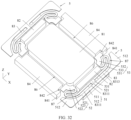
- FIG. 12 is a schematic exploded view of the vibration assembly 10b shown in FIG. 11 .
- the vibration assembly 10b of the electroacoustic transducer 10 includes the voice diaphragm 2, a connection frame 3, a voice coil 4, two flexible printed circuit boards 5, and four auxiliary vibration diaphragms 6.
- the voice coil 4 is in a rounded rectangular shape.
- the voice coil 4 includes four straight edges 41 and four round corners 42, and one round corner 42 is connected between two adjacent straight edges 41.
- Shapes of the voice diaphragm 2, the connection frame 3, the two flexible printed circuit boards 5, and the four auxiliary vibration diaphragms 6 are designed based on the shape of the voice coil 4. It can be understood that a length relationship between two adjacent straight edges 41 of the voice coil 4 is not strictly limited in this application.
- a length of a straight edge 41 may be greater than, equal to, or less than a length of an adjacent straight edge 41.
- the voice coil 4 is inserted in the magnetic circuit assembly 10c, and the magnetic circuit assembly 10c provides a magnetic field for driving the voice coil 4 to vibrate.
- the voice coil 4 drives other components of the vibration assembly 10b to vibrate.
- the voice coil 4 may be alternatively in a rectangular shape, and the following descriptions of the round corner 42 of the voice coil 4 correspond to the four corners of the voice coil 4.
- the voice coil 4 may alternatively have another shape, and a specific shape of the voice coil 4 is not strictly limited in this application.
- FIG. 13 is a schematic exploded view of the voice diaphragm 2 shown in FIG. 12
- FIG. 14 is a schematic structural diagram of the voice diaphragm 2 shown in FIG. 12 that is cut along D-D.
- the voice diaphragm 2 includes a vibration diaphragm 21 and a dome 22.
- the dome 22 is roughly in a rectangular plate shape.
- the dome 22 includes a top face 221 and a bottom face 222 that are disposed opposite to each other, and a peripheral region of the top face 221 of the dome 22 is concave to form a limiting groove 223.
- the vibration diaphragm 21 is roughly in a rectangular ring shape.
- the vibration diaphragm 21 includes a first fixed part 211, a vibrating part 212, and a second fixed part 213 that are connected in sequence.
- the first fixed part 211 is located on an inner side of the vibrating part 212
- the second fixed part 213 is located on an outer side of the vibrating part 212.
- the first fixed part 211 of the vibration diaphragm 21 is partially accommodated in the limiting groove 223 of the dome 22, and is fixed to the dome 22.
- a bottom face 2112 of the first fixed part 211 of the vibration diaphragm 21 is in contact with a bottom wall 2231 of the limiting groove 223 of the dome 22.
- a top face 2111 of the first fixed part 211 of the vibration diaphragm 21 is flush with the top face 221 of the dome 22.
- a cross-sectional shape of the vibrating part 212 of the vibration diaphragm 21 is an arc or approximately arc shape, and an extension track of the vibrating part 212 is in a rounded rectangular shape.
- the vibrating part 212 of the vibration diaphragm 21 is concave.
- the vibrating part 212 is concave in a direction away from the top face 2111 of the first fixed part 211 of the vibration diaphragm 21 and a top face 2131 of the second fixed part 213 of the vibration diaphragm 21.
- the vibrating part 212 of the vibration diaphragm 21 is subject to an external force, the vibrating part 212 can deform, so that the first fixed part 211 and the second fixed part 213 move relative to each other, and the dome 22 and the second fixed part 213 move relative to each other.
- the vibrating part 212 of the vibration diaphragm 21 is concave, an upper space of the electroacoustic transducer 10 can be saved, and after the vibration diaphragm 21 deforms under an influence of water pressure or air pressure, the vibration diaphragm 21 can easily restore.
- FIG. 15 is a schematic structural diagram of the voice diaphragm 2 in FIG. 12 according to another embodiment
- FIG. 16 is a schematic structural diagram of the voice diaphragm 2 shown in FIG. 15 that is cut along E-E.
- the voice diaphragm 2 includes a vibration diaphragm 21 and a dome 22.
- the dome 22 is roughly in a rectangular plate shape.
- the dome 22 includes a top face 221 and a bottom face 222 that are disposed opposite to each other, and a peripheral region of the bottom face 222 of the dome 22 is convex to form a limiting groove 223.
- the vibration diaphragm 21 is roughly in a rectangular ring shape.
- the vibration diaphragm 21 includes a first fixed part 211, a vibrating part 212, and a second fixed part 213 that are connected in sequence.
- the first fixed part 211 is located on an inner side of the vibrating part 212
- the second fixed part 213 is located on an outer side of the vibrating part 212.
- the first fixed part 211 of the vibration diaphragm 21 is partially accommodated in the limiting groove 223 of the dome 22, and is fixed to the dome 22.
- a top face 2111 of the first fixed part 211 of the vibration diaphragm 21 is in contact with a bottom wall 2231 of the limiting groove 223 of the dome 22.
- a bottom face 2112 of the first fixed part 211 of the vibration diaphragm 21 is flush with the bottom face 222 of the dome 22.
- a cross-sectional shape of the vibrating part 212 of the vibration diaphragm 21 is an arc or approximately arc shape, and an extension track of the vibrating part 212 is in a rounded rectangular shape.
- the vibrating part 212 of the vibration diaphragm 21 is convex.
- the vibrating part 212 is convex in a direction away from the bottom face 2112 of the first fixed part 211 of the vibration diaphragm 21 and a bottom face 2132 of the second fixed part 213 of the vibration diaphragm 21.
- the vibrating part 212 of the vibration diaphragm 21 is subject to an external force, the vibrating part 212 can deform, so that the first fixed part 211 and the second fixed part 213 move relative to each other, and the dome 22 and the second fixed part 213 move relative to each other.
- the vibrating part 212 of the vibration diaphragm 21 is convex, a space under the vibration diaphragm 21 is released, and a larger height size can be set for the magnetic circuit assembly 10c under the vibration diaphragm 21, thereby improving magnetic induction strength of the electroacoustic transducer 10, and improving sensitivity of the electroacoustic transducer 10.
- FIG. 17 is a schematic structural diagram of the connection frame 3 shown in FIG. 12 that is cut along F-F.
- connection frame 3 is roughly a Z shape, and an extension track of the connection frame 3 is in a rounded rectangular shape.
- the connection frame 3 includes a main part 31, an outer extension part 32, and an inner extension part 33.
- the outer extension part 32 is connected to a bottom face 311 of the main part 31 and extends toward an outer side of the main part 31.
- An area of a bottom face 321 of the outer extension part 32 is larger than an area of the bottom face 311 of the main part 31, to increase a connection area between the connection frame 3 and other components.
- the inner extension part 33 is connected to a top face 312 of the main part 31 and extends toward an inner side of the main part 31.
- An area of a top face 331 of the inner extension part 33 is greater than an area of the top face 312 of the main part 31, to increase a connection area between the connection frame 3 and other components.
- end faces of two ends of the connection frame 3 (that is, the bottom face 321 of the outer extension part 32 and the top face 331 of the inner extension part 33) have comparatively large areas, so that a connection area between the connection frame 3 and an external structure is comparatively large, and a connection relationship is more stable.
- the connection frame 3 may be integrated.
- the cross-sectional shape of the connection frame 3 may be alternatively a vertical bar shape, an L shape, an inverted L shape, a T shape, an inverted T shape, a " " shape, or the like.
- the cross-sectional shape of the connection frame 3 is not strictly limited in this application.
- the flexible printed circuit board 5 includes a body 51, a first stub 52, and a second stub 53.
- the body 51 includes a middle part 511 and two end parts 512 respectively connected to two sides of the middle part 511.
- the first stub 52 includes a head end 521, a tail end 522, and a connection section 523 connected between the head end 521 and the tail end 522.
- the second stub 53 includes a head end 531, a tail end 532, and a connection section 533 connected between the head end 531 and the tail end 532.
- the head end 521 of the first stub 52 and the head end 531 of the second stub 53 are both connected to the middle part 511 of the body 51.
- the head end 521 of the first stub 52 is connected to the head end 531 of the second stub 53, and then the two connected head ends are connected to the middle part 511 of the body 51.
- the head end 521 of the first stub 52 and the head end 531 of the second stub 53 each are connected to a different location in the middle part 511 of the body 51, and a gap is formed between the two head ends.
- the tail end 522 of the first stub 52 and the tail end 532 of the second stub 53 are spaced from each other, and are spaced from the body 51.
- the tail end 522 of the first stub 52 and the tail end 532 of the second stub 53 are movable end parts, and may move relative to the body 51.
- the connection section 523 of the first stub 52 may be driven to move relative to the body 51.
- the connection section 533 of the second stub 53 may be driven to move relative to the body 51.
- the auxiliary vibration diaphragm 6 is roughly in a fan shape.
- the auxiliary vibration diaphragm 6 includes a first fixed part 61, a vibrating part 62, and a second fixed part 63 that are connected in sequence.
- the first fixed part 61 is located on an inner side of the vibrating part 62
- the second fixed part 63 is located on an outer side of the vibrating part 62.
- a cross-sectional shape of the vibrating part 62 of the auxiliary vibration diaphragm 6 is an arc or approximately arc shape, and an extension track of the vibrating part 212 is in an arc shape.
- the vibrating part 62 of the auxiliary vibration diaphragm 6 is concave. To be specific, the vibrating part 62 is concave in a direction away from a top face 611 of the first fixed part 61 and a top face 631 of the second fixed part 63.
- the first fixed part 61 of the auxiliary vibration diaphragm 6 is in a fan shape.
- a notch 632 is formed on a side, away from the first fixed part 61, of the second fixed part 63 of the auxiliary vibration diaphragm 6.
- FIG. 18 is a schematic structural diagram of the vibration assembly 10b shown in FIG. 10 that is cut along G-G
- FIG. 19 is a schematic structural diagram of the vibration assembly 10b shown in FIG. 10 from another angle.
- One end of the voice coil 4 is fixedly connected to the voice diaphragm 2.
- the voice coil 4 is indirectly connected to the voice diaphragm 2 through the connection frame 3.
- the connection frame 3 is located between the voice coil 4 and the voice diaphragm 2.
- One end of the connection frame 3 is fixedly connected to the voice coil 4, and the other end of the connection frame 3 is fixedly connected to the voice diaphragm 2.
- the top face 331 of the inner extension part 33 of the connection frame 3 is in contact with the bottom face 222 of the dome 22 of the voice diaphragm 2, and the top face 331 and the bottom face 222 may be fixed to each other through bonding.
- the bottom face 321 of the outer extension part 32 of the connection frame 3 is in contact with the top face 43 of the voice coil 4, and the bottom face 321 and the top face 43 may be fixed to each other through bonding.
- An area of the bottom face 321 of the outer extension part 32 of the connection frame 3 may be smaller than an area of the top face 43 of the voice coil 4.
- connection frame 3 separates the voice coil 4 from the voice diaphragm 2, so that the voice diaphragm 2 is away from the voice coil 4.
- connection frame 3 may perform heat dissipation for the voice coil 4, thereby reducing a risk of damaging the voice diaphragm 2 due to overheating of the voice coil 4.
- the connection frame 3 is omitted from the electroacoustic transducer 10, and the voice coil 4 is directly connected to the voice diaphragm 2, to simplify a structure of the electroacoustic transducer 10.
- the two flexible printed circuit boards 5 are symmetrically arranged at intervals.
- the two flexible printed circuit boards 5 may be symmetrical relative to the first reference plane.
- the two flexible printed circuit boards 5 are located on outer sides of two edges of the voice coil 4.
- Tail ends (522 and 532) of two stubs of each flexible printed circuit board 5 are fixedly connected to two round corners 42 of the voice coil 4 respectively.
- the tail end 522 of the first stub 52 is fixedly connected to a round corner 42 of the voice coil 4
- the tail end 532 of the second stub 53 is fixedly connected to another round corner 42 of the voice coil 4.
- the voice coil 4 includes a left edge and a right edge arranged in the length direction X of the electroacoustic transducer 10, two left round corners connecting two ends of the left edge, and two right round corners connecting two ends of the right edge.
- the two flexible printed circuit boards 5 include a first flexible printed circuit board and a second flexible printed circuit board.
- the first flexible printed circuit board is located on an outer side of the left edge of the voice coil 4, and the second flexible printed circuit board is located on an outer side of the right edge of the voice coil 4.
- a tail end of a first stub of the first flexible printed circuit board and a tail end of a second stub of the first flexible printed circuit board are respectively connected to the two left round corners of the voice coil 4.
- a tail end of a first stub of the second flexible printed circuit board and a tail end of a second stub of the second flexible printed circuit board are respectively connected to the two right round corners of the voice coil 4.
- the tail ends (522 and 532) of the stubs of the flexible printed circuit board 5 are fixed to the bottom face 44 of the voice coil 4.
- the tail ends (522 and 532) of the stubs of the flexible printed circuit board 5 and the round corners 42 of the voice coil 4 may be fixed to each other through bonding.
- the voice coil 4 includes two sub-voice coils, and the two sub-voice coils are stacked in the thickness direction Z of the electroacoustic transducer 10. Two ends of a lead of one sub-voice coil each are electrically connected to a tail end of one stub of each of the two flexible printed circuit boards 5. Two ends of a lead of the other sub-voice coil each are electrically connected to a tail end of the other stub of each of the two flexible printed circuit boards 5.
- the two sub-voice coils include a first sub-voice coil and a second sub-voice coil.
- the tail end of the first stub of the first flexible printed circuit board is connected to one end of a lead of the first sub-voice coil
- the tail end of the first stub of the second flexible printed circuit board is connected to the other end of the lead of the first sub-voice coil
- the tail end of the second stub of the second flexible printed circuit board is connected to one end of a lead of the second sub-voice coil
- the tail end of the second stub of the first flexible printed circuit board is connected to the other end of the lead of the second sub-voice coil.
- a current may flow along the following track: "the tail end of the first stub of the first flexible printed circuit board - one end of the lead of the first sub-voice coil - the other end of the lead of the first sub-voice coil - the tail end of the first stub of the second flexible printed circuit board - the tail end of the second stub of the second flexible printed circuit board - one end of the lead of the second sub-voice coil - the other end of the lead of the second sub-voice coil - the tail end of the second stub of the first flexible printed circuit board".
- a connection relationship between the two sub-voice coils and the tail ends (522 and 532) of the two stubs of each of the two flexible printed circuit boards 5 may be alternatively different from that in the foregoing embodiment.
- the voice coil 4 may alternatively include more sub-voice coils.
- the voice coil 4 may further include a voice coil carrier, and a plurality of sub-voice coils are fixed to the voice coil carrier through winding. One end of the voice coil carrier is fixedly connected to the voice diaphragm, and the other end is partially inserted in the magnetic circuit assembly.
- the four auxiliary vibration diaphragms 6 are respectively located on outer sides of the four round corners 42 of the voice coil 4.
- the four auxiliary vibration diaphragms 6 are arranged at intervals on sides, away from the voice coil 4, of the two flexible printed circuit boards 5.
- One end (that is, the first fixed part 61) of each of the four auxiliary vibration diaphragms 6 is fixedly connected to each of tail ends 522 of first stubs 52 of the two flexible printed circuit boards 5 and tail ends 532 of second stubs 53 of the two flexible printed circuit boards 5.
- each auxiliary vibration diaphragm 6 is fixedly connected to an end part 512 of a body 51 of an adjacent flexible printed circuit board 5. Two ends of each auxiliary vibration diaphragm 6 can move relative to each other.
- the four auxiliary vibration diaphragms 6 include a first auxiliary vibration diaphragm and a second auxiliary vibration diaphragm that are located on outer sides of the left round corners the voice coil 4, and further include a third auxiliary vibration diaphragm and a fourth auxiliary vibration diaphragm that are located on outer sides of the right round corners of the voice coil 4.
- a first fixed part of the first auxiliary vibration diaphragm and a first fixed part of the second auxiliary vibration diaphragm are fixedly connected to the tail end of the first stub of the first flexible printed circuit board and the tail end of the second stub of the first flexible printed circuit board, respectively.
- a second fixed part of the first auxiliary vibration diaphragm and a second fixed part of the second auxiliary vibration diaphragm are fixedly connected to two end parts of a body of the first flexible printed circuit board respectively.
- a first fixed part of the third auxiliary vibration diaphragm and a first fixed part of the fourth auxiliary vibration diaphragm are fixedly connected to the tail end of the first stub of the second flexible printed circuit board and the tail end of the second stub of the second flexible printed circuit board, respectively.
- a second fixed part of the third auxiliary vibration diaphragm and a second fixed part of the fourth auxiliary vibration diaphragm are fixedly connected to two end parts of a body of the second flexible printed circuit board respectively.
- a part of the flexible printed circuit board 5 is exposed at an end at which the auxiliary vibration diaphragm 6 is fixed to the flexible printed circuit board 5.
- the end part 512 of the body 51 of the flexible printed circuit board 5 may be exposed through the notch 632 of the second fixed part 63 of the auxiliary vibration diaphragm 6.
- An exposed region of the end part 512 of the body 51 of the flexible printed circuit board 5 relative to the auxiliary vibration diaphragm 6 may be used for connecting another component of the electroacoustic transducer 10. For example, as shown in FIG.
- exposed regions of the two end parts 512 of the body 51 of the flexible printed circuit board 5 may be used for fixing (for example, welding) the tail ends of the two branches of the circuit board 40, to implement an electrical connection between the electroacoustic transducer 10 and an external device.
- FIG. 20 is a schematic structural assembly diagram of the flexible printed circuit board 5 and the voice coil 4 of the vibration assembly 10b shown in FIG. 10 .
- first stub 52 and the second stub 53 of the flexible printed circuit board 5 are symmetrically disposed.
- the first stub 52 and the second stub 53 may be symmetrical relative to the second reference plane.
- the connection section 523 of the first stub 52 includes a bent section 5231 and a straight section 5232.
- One end of the bent section 5231 is connected to the tail end 522 of the first stub 52, the other end of the bent section 5231 is connected to one end of the straight section 5232, and the other end of the straight section 5232 is connected to the head end 521 of the first stub 52.
- the bent section 5231 includes one or more arc sections 5233, and each arc section 5233 is disposed coaxially with a round corner 42, connected to the first stub 52, of the voice coil 4.
- that two structures are coaxially disposed means that central lines (or referred to as center lines) of the two structures overlap, and a slight deviation caused by a manufacturing tolerance, an assembly tolerance, or the like is allowed.
- the arc section 5233 of the bent section 5231 is disposed coaxially with the round corner 42 of the voice coil 4, when the voice coil 4 drives the flexible printed circuit board 5 to vibrate, a shape of the flexible printed circuit board 5 can better adapt to deformation and displacement requirements, so that the flexible printed circuit board 5 has higher reliability and a longer service life.
- the arc section 5233 is disposed coaxially with the round corner 42 of the voice coil 4, so that the bent section 5231 can fully utilize a space on an outer side of the round corner 42 of the voice coil 4, to route a longer wire, and when the flexible printed circuit board 5 vibrates with the voice coil 4 at a large amplitude, stress is comparatively small, and the flexible printed circuit board 5 has higher reliability.
- an end part 512, arranged close to the bent part, of the body 51 may have a comparatively large area, and the end part 512 of the body 51 not only has a sufficient area for fixing with the auxiliary vibration diaphragm 6, but also has a sufficient area for fixing with an external structure of the electroacoustic transducer 10.
- An extension direction of the straight section 5232 of the first stub 52 may be roughly parallel to the width direction Y of the electroacoustic transducer 10.
- the straight section 5232 is comparatively long, so that the flexible printed circuit board 5 is comparatively long, and a large amplitude is more easily implemented.
- the straight section 5232 occupies a comparatively small space in the length direction X of the electroacoustic transducer 10, thereby helping suppress spatial extrusion against the magnetic circuit assembly 10c by the flexible printed circuit board 5, so that the magnetic circuit assembly 10c has a larger arrangement space, to ensure magnetic induction strength and sensitivity of the electroacoustic transducer 10.
- the bent section 5231 of the first stub 52 further includes a plurality of transition sections 5234, and the transition section 5234 may be arranged between adjacent arc sections 5233, or may be arranged between the arc section 5233 and the straight section 5232, or may be arranged between the arc section 5233 and the tail end 522 of the first stub 52.
- FIG. 21 is a schematic structural assembly diagram of the auxiliary vibration diaphragm 6, the flexible printed circuit board 5, and the voice coil 4 of the vibration assembly 10b shown in FIG. 10 .
- an extension track of the vibrating part 62 of the auxiliary vibration diaphragm 6 is disposed coaxially with a round corner 42, connected to the auxiliary vibration diaphragm 6, of the voice coil 4.
- a shape of the vibrating part 62 of the auxiliary vibration diaphragm 6 can better adapt to deformation and displacement requirements, so that the auxiliary vibration diaphragm 6 has higher reliability and a longer service life.
- the arc section 5233 of the bent section 5231 of the stub of the flexible printed circuit board 5 is also disposed coaxially with the round corner 42 of the voice coil 4 (refer to FIG.
- the bent section 5231 of the stub of the flexible printed circuit board 5 and the vibrating part 62 of the auxiliary vibration diaphragm 6 have similar deformation trends in a process of vibrating with the voice coil 4, so that a risk of collision between the bent section 5231 and the vibrating part 62 can be reduced, and the electroacoustic transducer 10 has higher reliability.
- FIG. 22 is a schematic exploded view of the magnetic circuit assembly 10c shown in FIG. 10
- FIG. 23 is a partial schematic structural diagram of the magnetic circuit assembly 10c shown in FIG. 10 .
- the magnetic circuit assembly 10c of the electroacoustic transducer 10 includes a center electrode plate 71, a side electrode plate 72, a center magnet 81, two first side magnets 82, two second side magnets 83, two third side magnets 84, and a lower electrode plate 9.
- the center electrode plate 71, the side electrode plate 72, and the lower electrode plate 9 are magnetic conductive pieces.
- the center magnet 81, the two first side magnets 82, the two second side magnets 83, and the two third side magnets 84 are permanent magnets, and jointly form a magnet group.
- the lower electrode plate 9 is roughly in a chamfered rectangular shape.
- the lower electrode plate 9 includes a top face 91 and a bottom face 92 that are disposed opposite to each other, and a peripheral side face 93 connected between the top face 91 and the bottom face 92.
- the peripheral side face 93 includes four side edge faces 931 and four chamfered faces 932, and one chamfered face 932 is connected between two adjacent side edge faces 931. Two ends of each of two side edge faces 931 that are disposed opposite to each other are concave to form clamping spaces 9311.
- the lower electrode plate 9 forms four symmetrical clamping spaces 9311.
- the four clamping spaces 9311 may be symmetrical relative to the first reference plane, or may be symmetrical relative to the second reference plane.
- the top face 91 of the lower electrode plate 9 is provided with a center groove 911 and four corner grooves 912.
- the four corner grooves 912 are provided around the center groove 911, and are spaced from the center groove 911.
- the four corner grooves 912 are respectively located at four corners of the top face 303, and each corner groove 912 extends to a corresponding chamfered face 932 and side edge face 931.
- the center magnet 81, the two first side magnets 82, the two second side magnets 83, and the two third side magnets 84 are all fixed to the top face 91 of the lower electrode plate 9.
- the magnets may be fixed to the top face 91 of the lower electrode plate 9 through bonding.
- the lower electrode plate 9 is perpendicular to the thickness direction Z of the electroacoustic transducer 10.
- a thickness direction of the center magnet 81 is parallel to the thickness direction Z of the electroacoustic transducer 10.
- the center magnet 81 is roughly in a rounded rectangular shape or a rectangular shape.
- the center magnet 81 covers the center groove 911 of the lower electrode plate 9.
- the setting of the center groove 911 can not only reduce a weight of the lower electrode plate 9, but also reduce a connection area between a lower surface of the center magnet 81 and the top face 91 of the lower electrode plate 9, so that a face-to-face connection is easier to implement, and connection quality is higher.
- the center groove 911 may be alternatively omitted from the lower electrode plate 9.
- the two first side magnets 82 are symmetrically arranged on two sides of the center magnet 81, and a first gap 85 is formed between the first side magnet 82 and the center magnet 81.
- the two first side magnets 82 may be symmetrical relative to the first reference plane.
- the two second side magnets 83 are symmetrically arranged on two sides of the center magnet 81, and the second side magnet 83 is located on a side, away from the center magnet 81, of the first side magnet 82.
- the two second side magnets 83 may be symmetrical relative to the first reference plane.
- the second side magnet 83, the first side magnet 82, and the center magnet 81 are arranged in a first direction (that is, the length direction X of the electroacoustic transducer 10).
- a second side magnet 83 and a first side magnet 82 that are located on one side of the center magnet 81 are fixed to each other.
- two side faces, facing each other, of the second side magnet 83 and the first side magnet 82 are bonded to each other, to ensure reliability of the magnetic circuit assembly 10c.
- the two third side magnets 84 are symmetrically arranged on the other two sides of the center magnet 81, and a third gap 86 is formed between the third side magnet 84 and the center magnet 81.
- the two third side magnets 84 may be symmetrical relative to the second reference plane.
- the third side magnet 84 and the center magnet 81 are arranged in a second direction (that is, the width direction Y of the electroacoustic transducer 10).
- four connection spaces 87 are respectively formed on outer sides of four corners of the center magnet 81.
- Each connection space 87 connects a first gap 85 and a third gap 86 that are adjacent to each other, and is further connected to an outer side of the magnetic circuit assembly 10c.
- the four corner grooves 912 of the lower electrode plate 9 are connected to the four connection spaces 87 in a one-to-one correspondence, to form a space with a larger volume.
- the side electrode plate 72 includes a connection frame part 721, and two first electrode plate parts 722 and two second electrode plate parts 723 that are located on an inner side of the connection frame part 721.
- the two first electrode plate parts 722 are symmetrically connected to two straight edges of the connection frame part 721.
- the two second electrode plate parts 723 are symmetrically connected to the other two straight edges of the connection frame part 721.
- the two first electrode plate parts 722 may be symmetrical relative to the first reference plane, and the two second electrode plate parts 723 may be symmetrical relative to the second reference plane.
- the first electrode plate part 722 is roughly in a T shape.
- the first electrode plate part 722 includes a first part 7221 and a second part 7222.
- the second part 7222 connects the first part 7221 to the connection frame part 721.
- Avoidance gaps 7223 are formed on two sides of the second part 7222 of the first electrode plate part 722, and the avoidance gaps 7223 are located between the first part 7221 of the first electrode plate part 722 and the connection frame part 721.
- Each corner gap 724 is located between a first electrode plate part 722 and a second electrode plate part 723 that are adjacent to each other. Each corner gap 724 is connected to an adjacent avoidance gap 7223.
- At least one limiting hole 725 is formed on outer sides of two straight edges of the connection frame part 721. For example, a straight edge at which the limiting hole 725 is provided is the same as a straight edge connected to the second electrode plate part 723.
- FIG. 24 is a schematic structural diagram of the magnetic circuit assembly 10c shown in FIG. 10 that is cut along H-H.
- the center electrode plate 71 is fixed to a side, away from the lower electrode plate 9, of the center magnet 81.
- the center electrode plate 71 may be fixed to the center magnet 81 through bonding.
- the side electrode plate 72 is located on a side, away from the lower electrode plate 9, of the first side magnet 82, the second side magnet 83, and the third side magnet 84.
- the side electrode plate 72 is disposed around the center electrode plate 71.
- the corner gaps 724 of the side electrode plate 72 are connected to the connection spaces 87 on the outer sides of the four corners of the center magnet 81.
- the first electrode plate part 722 of the side electrode plate 72 is disposed directly opposite to the first side magnet 82 and the second side magnet 83.
- the first part 7221 of the first electrode plate part 722 is disposed directly opposite to the first side magnet 82
- the second part 7222 of the first electrode plate part 722 is disposed directly opposite to the second side magnet 83
- a straight-edge part, connected to the second part 7222 of the first electrode plate part 722, of the connection frame part 721 of the side electrode plate 72 is disposed directly opposite to the second side magnet 83.
- the first part 7221 of the first electrode plate part 722 may be fixed to the first side magnet 82 through bonding.
- a gap is formed between the second side magnet 83, and the second part 7222 of the first electrode plate part 722 and the connection frame part 721.
- a second gap 88 is formed between the first electrode plate part 722 and the center electrode plate 71. The second gap 88 is connected to the first gap 85. The second gap 88 is further connected to the corner gap 724 of the side electrode plate 72.
- FIG. 25 is a schematic structural diagram of the magnetic circuit assembly 10c shown in FIG. 10 that is cut along I-I.
- the second electrode plate part 723 of the side electrode plate 72 is disposed directly opposite to the third side magnet 84.
- a fourth gap 89 is formed between the second electrode plate part 723 and the center electrode plate 71.
- the fourth gap 89 is connected to the third gap 86.
- the fourth gap 89 is further connected to the corner gap 724 of the side electrode plate 72.
- a straight-side part, connected to the second electrode plate part 723, of the connection frame part 721 of the side electrode plate 72 is disposed directly opposite to the third side magnet 84.
- the third side magnet 84 fully utilizes a space between the side electrode plate 72 and the lower electrode plate 9, to have a larger size in the width direction Y of the electroacoustic transducer 10, so that the magnetic circuit assembly 10c has higher magnetic induction strength.
- the following describes a specific location relationship and connection relationship between the basin stand 1 and the components of the vibration assembly 10b and the magnetic circuit assembly 10c of the electroacoustic transducer 10. It can be understood that the components of the electroacoustic transducer 10 may be arranged as compactly as possible while meeting a requirement for a relative location relationship to meet a performance requirement for the electroacoustic transducer 10, so as to facilitate miniaturization, micro-miniaturization, and portability of the electroacoustic transducer 10.
- FIG. 26 is a schematic structural diagram of the electroacoustic transducer 10 shown in FIG. 9 that is cut along J-J
- FIG. 27 is a schematic structural diagram of the electroacoustic transducer 10 shown in FIG. 9 that is cut along K-K.
- a periphery of the voice diaphragm 2 is fixed to the first face 111 of the frame 11 of the basin stand 1.
- the vibration diaphragm 21 of the voice diaphragm 2 may be fixed to the first face 111 of the frame 11 of the basin stand 1 through bonding.
- a vibration direction of the voice diaphragm 2 is parallel to the thickness direction Z of the electroacoustic transducer 10.
- a space on an inner side of the frame 11 forms a shape that is narrow at the bottom and wide at the top, so that the vibrating part 212 of the vibration diaphragm 21 has a larger vibration space, thereby helping the voice diaphragm 2 implement large-amplitude vibration.
- the voice coil 4 is located on the inner side of the frame 11, and one end of the voice coil 4 is fixedly connected to the voice diaphragm 2.
- the voice coil 4 is connected to the voice diaphragm 2 through the connection frame 3.
- the connection frame 3 is fixedly connected to the dome 22 of the voice diaphragm 2.
- the connection frame 3 is fixedly connected to the vibration diaphragm 21.
- the lower electrode plate 9 is fixedly connected to the plurality of legs 12 of the basin stand 1 and is spaced from the frame 11. Tail ends of the plurality of legs 12 of the basin stand 1 may be accommodated in the clamping spaces 9311 (as shown in FIG. 22 ) of the lower electrode plate 9, and are fixed, through bonding, to surfaces, facing the clamping spaces 9311, of the lower electrode plate 9.
- a vertical direction of the lower electrode plate 9 is parallel to the thickness direction of the electroacoustic transducer.
- the center magnet 81, the two first side magnets 82, the two second side magnets 83, and the two third side magnets 84 are all fixed to a side, facing the frame 11, of the lower electrode plate 9.
- the two first side magnets 82 are located on two sides of the center magnet 81
- the two second side magnets 83 are located on two sides of the center magnet 81
- the first side magnet 82 is located between the second side magnet 83 and the center magnet 81.
- An end, away from the voice diaphragm 2, of the voice coil 4 is partially located in the first gap 85 between the first side magnet 82 and the center magnet 81.
- the two third side magnets 84 are located on the other two sides of the center magnet 81.
- the end, away from the voice diaphragm 2, of the voice coil 4 is partially located in the third gap 86 between the third side magnet 84 and the center magnet 81.
- the center electrode plate 71 is fixed to a side, facing the voice diaphragm 2, of the center magnet 81.
- the center electrode plate 71 is located between the center magnet 81 and the voice diaphragm 2.
- the electroacoustic transducer 10 is supported between the frame 11 and the lower electrode plate 9 by the plurality of legs 12.
- the plurality of legs 12 can play a supporting and connecting role while occupying a quite small space between the frame 11 and the lower electrode plate 9, so that a comparatively large magnetic circuit arrangement space is formed between the frame 11 and the lower electrode plate 9, and the space can be fully utilized for the magnetic circuit assembly 10c to arrange magnets, thereby achieving comparatively high magnetic induction strength and comparatively high sensitivity of the electroacoustic transducer 10.
- FIG. 28 is a schematic structural assembly diagram of the side electrode plate 72 and the basin stand 1 of the electroacoustic transducer 10 shown in FIG. 9 .
- the side electrode plate 72 is fixed to the inner side of the frame 11.
- the connection frame part 721 of the side electrode plate 72 may be clamped into the fixing groove 115 of the frame 11, the connection frame part 721 is partially located in the fixing groove 115 and partially located outside the fixing groove 115, and the first electrode plate part 722 and the second electrode plate part 723 of the side electrode plate 72 are located outside the fixing groove 115.
- the limiting strip 131 of the limiting block 13 of the basin stand 1 abuts against the connection frame part 721 of the side electrode plate 72.
- the at least one limiting leg 132 of the limiting block 13 is clamped into the at least one limiting hole 725 of the connection frame part 721 in a one-to-one correspondence.
- the two first electrode plate parts 722 of the side electrode plate 72 are respectively located on two sides of the center electrode plate 71, the second gap 88 is formed between the first electrode plate part 722 and the center electrode plate 71, the second gap 88 is connected to the first gap 85, and the voice coil 4 is partially located in the second gap 88.
- the two second electrode plate parts 723 of the side electrode plate 72 are respectively located on the other two sides of the center electrode plate 71, the fourth gap 89 is formed between the second electrode plate part 723 and the center electrode plate 71, the fourth gap 89 is connected to the third gap 86, and the voice coil 4 is partially located in the fourth gap 89.
- FIG. 29 is a schematic diagram of the magnetic circuit assembly 10c and the voice coil 4 shown in FIG. 26
- FIG. 30 is a schematic diagram of the magnetic circuit assembly 10c and the voice coil 4 shown in FIG. 27 .
- an end, close to the center electrode plate 71, of the center magnet 81 is an N pole; and an end, close to the lower electrode plate 9, of the center magnet 81 is an S pole.
- An end, close to the side electrode plate 72, of each of the first side magnet 82, the second side magnet 83, and the third side magnet 84 is an S pole; and an end, close to the lower electrode plate 9, of each of the first side magnet 82, the second side magnet 83, and the third side magnet 84 is an N pole.
- Paths of magnetic lines shown by dashed lines in FIG. 29 and FIG.
- the voice coil 4 is partially located in the second gap 88 and the fourth gap 89, and a magnetic assembly forms a magnetic field in the second gap 88 and the fourth gap 89. Therefore, when the voice coil 4 is electrically connected, an ampere force is produced to drive the voice coil 4 and the voice diaphragm 2 connected to the voice coil 4 to vibrate.
- the magnetic circuit assembly 10c is designed by using a structure with seven magnetic circuits, so that magnetic induction strength of the second gap 88 is quite high, and the magnetic circuit assembly 10c has sufficiently high magnetic induction strength, thereby increasing a driving force for the magnetic circuits.
- the voice coil 4 is electrically connected, the voice coil 4 is subject to a larger ampere force, and the electroacoustic transducer 10 has higher sensitivity.
- an end, close to the center electrode plate 71, of the center magnet 81 is an S pole; and an end, close to the lower electrode plate 9, of the center magnet 81 is an N pole.
- An end, close to the side electrode plate 72, of each of the first side magnet 82, the second side magnet 83, and the third side magnet 84 is an N pole; and an end, close to the lower electrode plate 9, of each of the first side magnet 82, the second side magnet 83, and the third side magnet 84 is an S pole.
- the voice coil 4 is connected to the voice diaphragm 2 through the connection frame 3. Therefore, a spacing between the voice diaphragm 2 and an end part, away from the voice diaphragm 2, of the voice coil 4 is comparatively large, so that the voice coil 4 can be fully inserted in the magnetic circuit assembly 10c, and a magnetic field generated by the magnetic circuit assembly 10c effectively acts on the voice coil 4. In addition, a spacing between the voice diaphragm 2 and the magnetic circuit assembly 10c is comparatively large, and a vibration space for the voice diaphragm 2 is comparatively large, thereby helping the voice diaphragm 2 implement large-amplitude vibration.
- FIG. 31 is a partial schematic structural diagram of the electroacoustic transducer 10 shown in FIG. 9 .
- FIG. 31 shows a location relationship between the flexible printed circuit board 5, the basin stand 1, and the side electrode plate 72.
- the two flexible printed circuit boards 5 are both partially fixed to the second face 112 of the frame 11 of the basin stand 1, and are symmetrically distributed at intervals.
- the tail ends (522 and 532) of the two stubs of the flexible printed circuit board 5 are fixedly connected to two round corners 42 of the voice coil 4 respectively.
- the body 51 of the flexible printed circuit board 5 is fixedly connected to the second face 112 of the frame 11, the first stub 52 and the second stub 53 of the flexible printed circuit board 5 are suspended relative to the frame 11, and the tail end 522 of the first stub 52 of the flexible printed circuit board 5 and the tail end 532 of the second stub 53 of the flexible printed circuit board 5 are fixedly connected to two round corners 42 of the voice coil 4 respectively.
- the flexible printed circuit board 5 and the side electrode plate 72 are spaced from each other.
- the body 51 of the flexible printed circuit board 5 and the side electrode plate 72 may be stacked at intervals in the thickness direction Z of the electroacoustic transducer 10, and the body 51 of the flexible printed circuit board 5 and the side electrode plate 72 that are fixed to the basin stand 1 are separated by some structures of the basin stand 1.
- the head end 521 of the first stub 52 of the flexible printed circuit board 5 directly faces the second part 7222 of the first electrode plate part 722 of the side electrode plate 72.
- the head end 521 of the first stub 52 and the second part 7222 of the first electrode plate part 722 are spaced from each other in the thickness direction Z of the electroacoustic transducer 10.
- the connection section 523 and the tail end 522 of the first stub 52 directly face an avoidance gap 7223 and a corner gap 724 on one side of the second part 7222 of the first electrode plate part 722.
- the first stub 52 When the first stub 52 vibrates under driving by the voice coil 4, an amplitude of the first stub 52 gradually decreases from the tail end 522 to the head end 521, and an amplitude of the head end 521 of the first stub 52 is quite small, or the head end 521 does not vibrate. Therefore, the first stub 52 can fully utilize the gaps of the side electrode plate 72 for vibration. In addition, the first stub 52 does not collide with the side electrode plate 72 during vibration, thereby helping improve reliability of the electroacoustic transducer 10.
- the head end 531 of the second stub 53 of the flexible printed circuit board 5 directly faces the second part 7222 of the first electrode plate part 722 of the side electrode plate 72.
- the head end 531 of the second stub 53 and the second part 7222 of the first electrode plate part 722 are spaced from each other in the thickness direction Z of the electroacoustic transducer 10.
- the connection section 533 and the tail end 532 of the second stub 53 directly face an avoidance gap 7223 and a corner gap 724 on the other side of the second part 7222 of the first electrode plate part 722.
- the second stub 53 When the second stub 53 vibrates under driving by the voice coil 4, an amplitude of the second stub 53 gradually decreases from the tail end 532 to the head end 531, and an amplitude of the head end 531 of the second stub 53 is quite small, or the head end 531 does not vibrate. Therefore, the second stub 53 can fully utilize the gaps of the side electrode plate 72 for vibration. In addition, the second stub 53 does not collide with the side electrode plate 72 during vibration, thereby helping improve reliability of the electroacoustic transducer 10.
- FIG. 32 is another partial schematic structural diagram of the electroacoustic transducer 10 shown in FIG. 9 .
- FIG. 32 shows a location relationship between the flexible printed circuit board 5 and the magnets of the magnetic circuit assembly 10c.
- the two flexible printed circuit boards 5 are symmetrically arranged on two sides of the center magnet 81.
- the flexible printed circuit board 5 is located on a side, away from the center magnet 81, of the first side magnet 82.
- the first side magnet 82 is located between the flexible printed circuit board 5 and the center magnet 81.
- the flexible printed circuit board 5 is located between the second side magnet 83 and the voice diaphragm 2.
- the second side magnet 83 is located between the flexible printed circuit board 5 and the lower electrode plate 9.
- the electroacoustic transducer 10 in this embodiment Compared with a conventional electroacoustic transducer in which flexible printed circuit boards are arranged on a side magnet and a center magnet, in the electroacoustic transducer 10 in this embodiment, a relative location relationship between the flexible printed circuit board 5 and the first side magnet 82 is changed, so that the gap between the first side magnet 82 and the center magnet 81 is narrower, and the magnetic circuit assembly 10c has higher magnetic induction strength, thereby helping improve sensitivity of the electroacoustic transducer 10.
- a pair of second side magnets 83 is additionally disposed in a space between the flexible printed circuit board 5 and the lower electrode plate 9, so that magnetic induction strength of the magnetic circuit assembly 10c is effectively improved, a driving force for the magnetic circuit assembly 10c is significantly increased, and the electroacoustic transducer 10 has higher sensitivity.
- a conventional structure with five magnetic circuits (including one center magnet and four side magnets) is modified into a structure with seven magnetic circuits. (including one center magnet and six side magnets), so that sensitivity of the electroacoustic transducer 10 can be improved by 0.2 dB to 0.8 dB.
- the first side magnet 82 is spaced from the flexible printed circuit board 5.
- a spacing between the first side magnet 82 and the flexible printed circuit board 5 may range from 0.1 millimeters to 0.5 millimeters.
- the second side magnet 83 is spaced from the flexible printed circuit board 5. In the thickness direction Z of the electroacoustic transducer 10, a spacing between the flexible printed circuit board 5 and the second side magnet 83 may range from 0.1 millimeters to 0.7 millimeters.
- the spacing between the flexible printed circuit board 5 and the first side magnet 82 and the spacing between the flexible printed circuit board 5 and the second side magnet 83 may be designed according to a specific requirement of the electroacoustic transducer 10. This is not strictly limited in this embodiment of this application.
- a height of the first side magnet 82 is greater than a height of the second side magnet 83.
- the height of the first side magnet 82 may be greater than the height of the second side magnet 83, to fully utilize a space and improve magnetic induction strength of the magnetic circuit assembly 10c, so that the electroacoustic transducer 10 has comparatively high sensitivity.
- the height of the first side magnet 82 may be greater than a sum of the height of the second side magnet 83, a height of the flexible printed circuit board 5, and the spacing between the second side magnet 83 and the flexible printed circuit board 5.
- the third side magnet 84 is spaced from the flexible printed circuit board 5.
- each of two ends of the third side magnet 84 is close to a tail end (522 or 532) of a stub of the flexible printed circuit board 5.
- An end face 841 of each of the two ends of the third side magnet 84 is partially concave to form an avoidance region 842.
- the avoidance region 842 is connected to the third gap 86.
- the tail end (522 or 532) of the stub of the flexible printed circuit board 5 is partially located in the avoidance region 842, and forms a gap with a wall surface of the avoidance region 842.
- FIG. 33 is a schematic structural diagram of the electroacoustic transducer 10 shown in FIG. 9 that is cut along L-L.
- the body 51 of the flexible printed circuit board 5 is fixed to the basin stand 1, and the tail end 522 of the first stub 52 of the flexible printed circuit board 5 and the tail end 532 of the second stub 53 of the flexible printed circuit board 5 are fixedly connected to two round corners 42 of the voice coil 4 respectively.
- the tail end 522 of the first stub 52 and the tail end 532 of the second stub 53 vibrate with the voice coil 4, amplitudes gradually decrease from the tail end 522 of the first stub 52 to the connection section 523 of the first stub 52 to the head end 521 of the first stub 52, amplitudes gradually decrease from the tail end 532 of the second stub 53 to the connection section 533 of the second stub 53 to the head end 531 of the second stub 53, and amplitudes of the head end 521 of the first stub 52 and the head end 531 of the second stub 53 are quite small.
- the two end parts 512 of the body 51 of the flexible printed circuit board 5 are disposed directly opposite to the connection spaces 87 of the magnetic circuit assembly 10c, and the middle part 511 of the body 51 is disposed directly opposite to the second side magnet 83.
- the head end 521 of the first stub 52 and the head end 531 of the second stub 53 are disposed directly opposite to the second side magnet 83.
- a part that is of the connection section 523 of the first stub 52 and that is close to the head end 521 is disposed directly opposite to the second side magnet 83, and a part that is of the connection section 523 of the first stub 52 and that is away from the head end 521 is disposed directly opposite to the connection space 87.
- connection section 533 of the second stub 53 and that is close to the head end 531 is disposed directly opposite to the second side magnet 83, and a part that is of the connection section 533 of the second stub 53 and that is away from the head end 531 is disposed directly opposite to the connection space 87.
- the tail end 522 of the first stub 52 and the tail end 532 of the second stub 53 are disposed directly opposite to the connection space 87.
- the first stub 52 and the second stub 53 of the flexible printed circuit board 5 can vibrate by using the connection space 87 of the magnetic circuit assembly 10c.
- the second side magnet 83 is disposed directly opposite to the head end 521 of the first stub 52, the head end 531 of the second stub 53, and the middle part 511 of the body 51. Therefore, the second side magnet 83 can fully utilize a space under the flexible printed circuit board 5 in the length direction X of the electroacoustic transducer 10, so that the second side magnet 83 has a comparatively large size, to effectively improve magnetic induction strength of the magnetic circuit assembly 10c.
- the second side magnet 83 directly faces the head end 521 of the first stub 52 with a comparatively small amplitude, a part of the connection section 523 that is close to the head end 521, the head end 531 of the second stub 53, and a part of the connection section 533 that is close to the head end 531. Therefore, the second side magnet 83 can fully utilize a space under the flexible printed circuit board 5 in the width direction Y of the electroacoustic transducer 10, so that the second side magnet 83 has a comparatively large size, to effectively improve magnetic induction strength of the magnetic circuit assembly 10c.
- one end of the auxiliary vibration diaphragm 6 is connected to the end part 512 of the body 51 of the flexible printed circuit board 5, and the other end is connected to a tail end (522 or 532) of a stub of the flexible printed circuit board 5.
- the auxiliary vibration diaphragm 6 is located in the connection space 87 of the magnetic circuit assembly 10c, and vibrates in the connection space 87.
- the electroacoustic transducer 10 includes two compliant systems.
- the voice diaphragm 2 is a first compliant system located above the voice coil 4, and the flexible printed circuit board 5 and the auxiliary vibration diaphragm 6 are a second compliant system located under the voice coil 4.
- the two compliant systems vibrate with the voice coil 4, to suppress rolling vibration of the voice coil 4, and ensure comparatively good sound quality of the electroacoustic transducer 10.
- a compliance coefficient of the compliant system is a reciprocal of an elasticity coefficient, and a component with a higher compliance coefficient is more likely to deform under a force.
- the voice diaphragm 2 has comparatively high hardness and comparatively low compliance, so that the voice diaphragm 2 can smoothly push air to produce sound; and the flexible printed circuit board 5 and the auxiliary vibration diaphragm 6 have comparatively low hardness and comparatively high compliance, so that total hardness of the two compliant systems is appropriate, thereby ensuring a comparatively large sound volume of the electroacoustic transducer 10.
- Hardness of the auxiliary vibration diaphragm 6 is greater than hardness of the flexible printed circuit board 5, so that the second compliant system has comparatively high hardness and stability, to better suppress swinging of the voice coil 4, and reduce a rolling range of the voice coil 4.
- FIG. 34 is a schematic structural diagram of the first side magnet 82 and the second side magnet 83 shown in FIG. 32 .
- a shape of the second side magnet 83 is designed based on vibration amplitudes of the first stub 52 and the second stub 53 of the flexible printed circuit board 5.
- the second side magnet 83 includes a first surface 831 and a second surface 832 that are disposed opposite to each other.
- the first surface 831 faces the flexible printed circuit board 5.
- the second surface 832 is fixed to the lower electrode plate 9 (as shown in FIG. 23 ), and the second surface 832 is planar.
- the first surface 831 includes a first plane 8311, a first inclined plane 8312, and a second inclined plane 8313.
- the first plane 8311 directly faces the head end 521 of the first stub 52 and the head end 531 of the second stub 53, and the first plane 8311 is parallel to the second surface 832.
- the first inclined plane 8312 faces the connection section 523 of the first stub 52, one end of the first inclined plane 8312 is connected to one end of the first plane 8311, and the other end of the first inclined plane 8312 extends in a direction toward the second surface 832.
- the second inclined plane 8313 faces the connection section 523 of the first stub 52, one end of the second inclined plane 8313 is connected to the other end of the first plane 8311, and the other end of the second inclined plane 8313 extends in a direction toward the second surface 832.
- the second side magnet 83 has a structure in which the middle is high and heights on two sides gradually decrease. A location in the middle that is high directly faces a part, with a small amplitude, of the flexible printed circuit board 5. A location on the two sides on which the heights gradually decrease directly faces a part, with a gradually increasing amplitude, of the flexible printed circuit board 5. Therefore, an abundant vibration space can be reserved for the flexible printed circuit board 5, and further, a non-interfering height can be fully utilized, and a magnet size can be increased, so that the electroacoustic transducer 10 has higher magnetic induction strength.
- a size of the second side magnet 83 in the width direction Y of the electroacoustic transducer 10 may range from 2 millimeters to 10 millimeters.
- the first plane 8311 may directly face another part, with a comparatively small amplitude, of the flexible printed circuit board 5, for example, the part that is of the connection section 523 of the first stub 52 and that is close to the head end 521, and the part that is of the connection section 533 of the second stub 53 and that is close to the head end 531.
- the second side magnet 83 has a larger volume, and magnetic induction strength of the electroacoustic transducer 10 can be improved.
- the second inclined plane 8313 and the first inclined plane 8312 may be symmetrically disposed, and the symmetrical planes are perpendicular to the second surface 832.
- the second inclined plane 8313 and the first inclined plane 8312 may be symmetrical relative to the second reference plane. Because the first stub 52 and the second stub 53 of the flexible printed circuit board 5 are symmetrically disposed, and vibration amplitudes of the first stub 52 and the second stub 53 are symmetrical, the second inclined plane 8313 and the first inclined plane 8312 that are symmetrically disposed can better match vibration statuses of the first stub 52 and the second stub 53.
- the first side magnet 82 is in a cuboid shape.
- the second side magnet 83 further includes two side surfaces (833 and 834) that are disposed opposite to each other.
- the side surface 833 connects one end of the second surface 832 to an end, away from the first plane 8311, of the first inclined plane 8312.
- the side surface 834 connects the other end of the second surface 832 to an end, away from the first plane 8311, of the second inclined plane 8313.
- the first side magnet 82 and the second side magnet 83 are designed in a separated manner, and may be fixed to each other by bonding adjacent surfaces. Because the second side magnet 83 and the first side magnet 82 have different shapes on a YZ plane (that is, a plane on which the width direction Y and the thickness direction Z of the electroacoustic transducer 10 are located), the second side magnet 83 and the first side magnet 82 are separately molded and then assembled to form an integrated structure, so that costs can be reduced, and costs of the electroacoustic transducer 10 are lower.
- a YZ plane that is, a plane on which the width direction Y and the thickness direction Z of the electroacoustic transducer 10 are located
- first side magnet 82 and the second side magnet 83 may be alternatively an integrated irregularly-shaped magnet.
- FIG. 35 is a schematic structural diagram of the first side magnet 82 and the second side magnet 83 shown in FIG. 32 according to another embodiment
- FIG. 36 is a schematic diagram of a location relationship between the first side magnet 82 and the second side magnet 83 shown in FIG. 35 and the flexible printed circuit board 5.
- the following mainly describes differences between this embodiment and the foregoing embodiments, and most content that is the same in the embodiments is not described again.
- a size of the second side magnet 83 in the width direction Y of the electroacoustic transducer 10 is a second width W2.
- a size of the first side magnet 82 in the width direction Y of the electroacoustic transducer 10 is a first width W1.
- the second width W2 is less than the first width W1.
- the width of the second side magnet 83 in the width directionY of the electroacoustic transducer 10 is comparatively small, and the second side magnet 83 directly faces a part, with a small amplitude, of the flexible printed circuit board 5, for example, the head end 521 of the first stub 52 and the head end 531 of the second stub 53.
- Spaces on two sides of the second side magnet 83 in the width direction Y of the electroacoustic transducer 10 may be used as vibration spaces for the flexible printed circuit board 5, and directly face a part, with a comparatively large amplitude, of the flexible printed circuit board 5, for example, the connection section 523 of the first stub 52 and the connection section 533 of the second stub 53.
- the second side magnet 83 may directly face another part, with a comparatively small amplitude, of the flexible printed circuit board 5, for example, the part that is of the connection section 523 of the first stub 52 and that is close to the head end 521, and the part that is of the connection section 533 of the second stub 53 and that is close to the head end 531, to have a larger volume.
- the first surface 831 of the second side magnet 83 is parallel to the second surface 832, and the second side magnet 83 is in a cuboid shape.
- the second width W2 of the second side magnet 83 may be appropriately increased, or a height of the second side magnet 83 may be reduced and the second width W2 of the second side magnet 83 may be greatly increased (in this case, the second width W2 may be greater than or equal to the first width W1 of the first side magnet 82), so that the second side magnet 83 has a larger volume.
- FIG. 37 is a schematic structural diagram of the first side magnet 82 and the second side magnet 83 shown in FIG. 32 according to still another embodiment
- FIG. 38 is a schematic diagram of a location relationship between the first side magnet 82 and the second side magnet 83 shown in FIG. 37 and the flexible printed circuit board 5.
- the following mainly describes differences between this embodiment and the foregoing embodiments, and most content that is the same in the embodiments is not described again.
- a cross section, parallel to the YZ plane, of the second side magnet 83 is in a trapezoidal shape.
- the first surface 831 of the second side magnet 83 is parallel to the second surface 832.
- the first surface 831 directly faces the head end 521 of the first stub 52 of the flexible printed circuit board 5 and the head end 531 of the second stub 53 of the flexible printed circuit board 5.
- the second side magnet 83 further includes a first side face 835 and a second side face 836.
- the first side face 835 connects one end of the first surface 831 to one end of the second surface 832.
- the second side face 836 connects the other end of the first surface 831 to the other end of the second surface 832.
- the first side face 835 directly faces the connection section 523 of the first stub 52.
- the second side face 836 directly faces the connection section 533 of the second stub 53.
- FIG. 39 is a schematic structural diagram of the first side magnet 82 and the second side magnet 83 shown in FIG. 32 according to still another embodiment
- FIG. 40 is a schematic diagram of a location relationship between the first side magnet 82 and the second side magnet 83 shown in FIG. 39 and the flexible printed circuit board 5.
- the following mainly describes differences between this embodiment and the foregoing embodiments, and most content that is the same in the embodiments is not described again.
- the first side magnet 82 and the second side magnet 83 are integrated.
- a cross-sectional shape of the first side magnet 82 is the same as a cross-sectional shape of the second side magnet 83.
- a cross section of the first side magnet 82 and a cross section of the second side magnet 83 are both perpendicular to the length direction X of the electroacoustic transducer 10.
- a height of the first side magnet 82 is lower than that in the foregoing embodiment, and a plurality of outer surfaces of the first side magnet 82 that are parallel to the length direction X of the electroacoustic transducer 10 are coplanar with the second side magnet 83, so that the first side magnet 82 and the second side magnet 83 can be integrated, to simplify an assembly process and improve assembly precision.
- a location relationship between the flexible printed circuit board 5 and each plane of the first surface 831 of the second side magnet 83 may be the same as that in the foregoing embodiment, and the first side magnet 82 is arranged based on a location of the second side magnet 83.
- FIG. 41 is a schematic structural diagram of the first side magnet 82 and the second side magnet 83 in FIG. 32 according to still another embodiment. The following mainly describes differences between this embodiment and the foregoing embodiments, and most content that is the same in the embodiments is not described again.
- the first side magnet 82 and the second side magnet 83 are integrated.
- a height H1 of the first side magnet 82 is the same as a height H2 of the second side magnet 83.
- a size of the second side magnet 83 in the width direction Y of the electroacoustic transducer 10 is a second width W2.
- a size of the first side magnet 82 in the width direction Y of the electroacoustic transducer 10 is a first width W1.
- the second width W2 is less than the first width W1.
- the first side magnet 82 in this embodiment has a lower height H1, and two surfaces of the first side magnet 82 and two surfaces of the second side magnet 83 that are in a direction parallel to the XY plane are separately coplanar, so that the first side magnet 82 and the second side magnet 83 can be integrated, to simplify an assembly process and improve assembly precision.
- FIG. 42 is a schematic structural diagram of the first side magnet 82 and the second side magnet 83 shown in FIG. 32 according to still another embodiment
- FIG. 43 is a schematic diagram of a location relationship between the first side magnet 82 and the second side magnet 83 shown in FIG. 42 and the flexible printed circuit board 5.
- the following mainly describes differences between this embodiment and the foregoing embodiments, and most content that is the same in the embodiments is not described again.
- the second side magnet 83 includes a first magnetic part 83a and a second magnetic part 83b.
- the first magnetic part 83a is located between the second magnetic part 83b and the first side magnet 82.
- the second magnetic part 83b is disposed directly opposite to the body 51 of the flexible printed circuit board 5.
- the first magnetic part 83a is disposed directly opposite to the head end 521 of the first stub 52 of the flexible printed circuit board 5 and the head end 531 of the second stub 53 of the flexible printed circuit board 5.
- the first magnetic part 83a may be disposed directly opposite to the part that is of the connection section 523 of the first stub 52 and that is close to the head end 521, and the part that is of the connection section 533 of the second stub 53 and that is close to the head end 531.
- a length of the first magnetic part 83a in the length direction X of the electroacoustic transducer 10 is less than that of the second side magnet 83 in the foregoing embodiment.
- a length of the first magnetic part 83a in the length direction X of the electroacoustic transducer 10 is less than that of the second side magnet 83 in the foregoing embodiment.
- a height H4 of the second magnetic part 83b is greater than a height H3 of the first magnetic part 83a, and the height H4 of the second magnetic part 83b is less than the height H1 of the first side magnet 82.
- a top face of the second magnetic part 83b may be in contact with the body 51 of the flexible printed circuit board 5, to fully utilize a space under the flexible printed circuit board 5.
- the first magnetic part 83a and the second magnetic part 83b may be integrated, or may be assembled (for example, bonded) to form an integrated structure.
- first side magnet 82 and the second side magnet 83 described in the foregoing embodiments may be combined to form a new embodiment.
- FIG. 44 is a schematic structural diagram of the flexible printed circuit board 5, the first side magnet 82, and the second side magnet 83 in FIG. 32 according to still another embodiment
- FIG. 45 is a schematic structural diagram of the first side magnet 82 and the second side magnet 83 shown in FIG. 44 .
- the following mainly describes differences between this embodiment and the foregoing embodiments, and most content that is the same in the embodiments is not described again.
- the flexible printed circuit board 5 includes a body 51, a first stub 52, and a second stub 53.
- the body 51 includes a middle part 511 and two end parts 512 respectively connected to two sides of the middle part 511.
- a head end 521 of the first stub 52 and a head end 531 of the second stub 53 are respectively connected to the two end parts 512 of the body 51.
- the second side magnet 83 directly faces the middle part 511 of the body 51 of the flexible printed circuit board 5.
- the two first side magnets 82 are located between the two second side magnets 83.
- the first stub 52 and the second stub 53 of the flexible printed circuit board 5 are connected to the two end parts 512 of the body 51, a space on an inner side of the middle part 511 of the body 51 is released.
- a length of the second side magnet 83 is reduced, and a length of the first side magnet 82 is increased, so that the magnetic circuit assembly 10c has higher magnetic induction strength.
- the length L1 of the first side magnet 82 may be greater than the length L2 of the second side magnet 83.
- the first side magnet 82 is in a cuboid shape
- the second side magnet 83 is in a cuboid shape.
- a height H1 of the first side magnet 82 may be greater than a height H2 of the second side magnet 83.
- a width W2 of the second side magnet 83 may be greater than a width W1 of the first side magnet 82.
Landscapes
- Engineering & Computer Science (AREA)
- Physics & Mathematics (AREA)
- Acoustics & Sound (AREA)
- Signal Processing (AREA)
- Multimedia (AREA)
- Audible-Bandwidth Dynamoelectric Transducers Other Than Pickups (AREA)
Description
- Embodiments of this application relate to the field of audio technologies, and in particular, to an electroacoustic transducer, a speaker module, and an electronic device.
- A moving coil micro-speaker is an electroacoustic transducer, and is an audio assembly commonly used in a portable electronic device currently. As consumers require increasingly high sound quality of electronic devices, speakers usually need to be designed with larger amplitudes. Currently, a speaker includes a voice coil and a wire connected to the voice coil. Because the wire needs to vibrate with the voice coil at a large amplitude, a flexible printed circuit (flexible printed circuit, FPC) board is used to form the wire in the industry, to reduce a risk of wire fracture due to fatigue.
- The voice coil is inserted in a magnetic circuit of the speaker, and the flexible printed circuit board needs to vibrate with the voice coil in the magnetic circuit. Therefore, a structural size of the flexible printed circuit board and a size of the magnetic circuit of the speaker affect each other, and a specific design gap further needs to be reserved between the flexible printed circuit board and the magnetic circuit of the speaker, to prevent the flexible printed circuit board from colliding with the magnetic circuit during vibration. Therefore, when a comparatively long design size is used for the flexible printed circuit board to reduce local stress during large-amplitude vibration, the size of the magnetic circuit is shortened, thereby reducing a driving force for the speaker, and causing poor sensitivity of the speaker.
-
CN 209 526 874 U discloses a speaker assembly for a portable mobile device. - An objective of this application is to provide an electroacoustic transducer, a speaker module, and an electronic device with comparatively high sensitivity.
- The present invention is defined in the appended independent claims. Further implementations are disclosed in the pending dependent claims. In the following, implementations not falling within the scope of the claims are to be understood as examples useful for understanding the claims.
- According to a first aspect, an embodiment of this application provides an electroacoustic transducer according to
claim 1. The electroacoustic transducer is configured to convert an electrical signal into a sound signal. The electroacoustic transducer includes a center magnet, two first side magnets, two second side magnets, a voice coil, a voice diaphragm, and two flexible printed circuit boards. The two first side magnets are symmetrically arranged on two sides of the center magnet, and a first gap is formed between the first side magnet and the center magnet. The two second side magnets are symmetrically arranged on two sides of the center magnet, and the second side magnet is located on a side, away from the center magnet, of the first side magnet. One end of the voice coil is partially located in the first gap, and the voice diaphragm is fixedly connected to the other end of the voice coil. The two flexible printed circuit boards are symmetrically arranged on two sides of the center magnet. The flexible printed circuit board is located on a side, away from the center magnet, of the first side magnet, and is located between the second side magnet and the voice diaphragm. Tail ends of two stubs of the flexible printed circuit board are fixedly connected to two corners of the voice coil respectively. - Compared with a conventional electroacoustic transducer in which flexible printed circuit boards are arranged on a side magnet and a center magnet, in the electroacoustic transducer in this embodiment, a relative location relationship between the flexible printed circuit board and the first side magnet is changed, so that the gap between the first side magnet and the center magnet is narrower, and a magnetic circuit of the electroacoustic transducer has higher magnetic induction strength, thereby helping improve sensitivity of the electroacoustic transducer. In addition, in the electroacoustic transducer, a pair of second side magnets is additionally disposed in a space under the flexible printed circuit boards, so that magnetic induction strength of the magnetic circuit of the electroacoustic transducer is effectively improved, a driving force for the magnetic circuit is significantly increased, and the electroacoustic transducer has higher sensitivity.
- In some embodiments, the first side magnet is spaced from the flexible printed circuit board. For example, on an XY plane of the electroacoustic transducer (that is, a plane on which a length direction of the electroacoustic transducer and a width direction of the electroacoustic transducer are located), a spacing between the first side magnet and the flexible printed circuit board may range from 0.1 millimeters to 0.5 millimeters. In this case, when vibrating with the voice coil, the flexible printed circuit board does not collide with the first side magnet, thereby ensuring reliability of the flexible printed circuit board.
- In some embodiments, the second side magnet is spaced from the flexible printed circuit board. In a thickness direction of the electroacoustic transducer, a spacing between the flexible printed circuit board and the second side magnet may range from 0.1 millimeters to 0.7 millimeters. In this case, when vibrating with the voice coil, the flexible printed circuit board does not collide with the second side magnet, thereby ensuring reliability of the flexible printed circuit board.
- The electroacoustic transducer further includes a basin stand. A frame of the basin stand includes a first face and a second face that are opposite to each other. A periphery of the voice diaphragm is fixed to the first face of the frame. The voice coil is located on an inner side of the frame. The two flexible printed circuit boards are both partially fixed to the second face of the frame. A part, not fixed to the frame, of the flexible printed circuit board may vibrate with the voice coil relative to the frame.
- The voice diaphragm and the flexible printed circuit board are both fixed to the frame of the basin stand, so that assembly precision of the voice diaphragm and the flexible printed circuit board are comparatively high, and when the voice coil vibrates, the voice diaphragm fixed to an upper end of the frame and the flexible printed circuit board fixed to a lower end of the frame can be better synchronously driven, and a probability of rolling vibration of the voice coil is low, so that the electroacoustic transducer has comparatively good sound quality.
- For example, the periphery of the voice diaphragm may be fixed to the first face of the frame of the basin stand through bonding. A vibration direction of the voice diaphragm is parallel to the thickness direction of the electroacoustic transducer. A space on the inner side of the frame forms a shape that is narrow at the bottom and wide at the top, so that the voice diaphragm has a larger vibration space, thereby helping the voice diaphragm implement large-amplitude vibration.
- In an embodiment, the voice diaphragm includes a vibration diaphragm and a dome. The dome is roughly in a rectangular plate shape. The dome includes a top face and a bottom face that are disposed opposite to each other, and a peripheral region of the top face of the dome is concave to form a limiting groove. The vibration diaphragm is roughly in a rectangular ring shape. The vibration diaphragm includes a first fixed part, a vibrating part, and a second fixed part that are connected in sequence. The first fixed part is located on an inner side of the vibrating part, and the second fixed part is located on an outer side of the vibrating part. The first fixed part of the vibration diaphragm is partially accommodated in the limiting groove of the dome, and is fixed to the dome. A bottom face of the first fixed part of the vibration diaphragm is in contact with a bottom wall of the limiting groove of the dome. For example, a top face of the first fixed part of the vibration diaphragm is flush with the top face of the dome. A cross-sectional shape of the vibrating part of the vibration diaphragm is an arc or approximately arc shape, and an extension track of the vibrating part is in a rounded rectangular shape. The vibrating part of the vibration diaphragm is concave. To be specific, the vibrating part is concave in a direction away from the top face of the first fixed part of the vibration diaphragm and a top face of the second fixed part of the vibration diaphragm. In this case, when the vibrating part of the vibration diaphragm is subject to an external force, the vibrating part can deform, so that the first fixed part and the second fixed part move relative to each other, and the dome and the second fixed part move relative to each other.
- In this embodiment, because the vibrating part of the vibration diaphragm is concave, an upper space of the electroacoustic transducer can be saved, and after the vibration diaphragm deforms under an influence of water pressure or air pressure, the vibration diaphragm can easily restore.
- In another embodiment, the voice diaphragm includes a vibration diaphragm and a dome. The dome is roughly in a rectangular plate shape. The dome includes a top face and a bottom face that are disposed opposite to each other, and a peripheral region of the bottom face of the dome is convex to form a limiting groove. The vibration diaphragm is roughly in a rectangular ring shape. The vibration diaphragm includes a first fixed part, a vibrating part, and a second fixed part that are connected in sequence. The first fixed part is located on an inner side of the vibrating part, and the second fixed part is located on an outer side of the vibrating part. The first fixed part of the vibration diaphragm is partially accommodated in the limiting groove of the dome, and is fixed to the dome. A top face of the first fixed part of the vibration diaphragm is in contact with a bottom wall of the limiting groove of the dome. For example, a bottom face of the first fixed part of the vibration diaphragm is flush with the bottom face of the dome. A cross-sectional shape of the vibrating part of the vibration diaphragm is an arc or approximately arc shape, and an extension track of the vibrating part is in a rounded rectangular shape. The vibrating part of the vibration diaphragm is convex. To be specific, the vibrating part is convex in a direction away from the bottom face of the first fixed part of the vibration diaphragm and a bottom face of the second fixed part of the vibration diaphragm. When the vibrating part of the vibration diaphragm is subject to an external force, the vibrating part can deform, so that the first fixed part and the second fixed part move relative to each other, and the dome and the second fixed part move relative to each other.
- In this embodiment, because the vibrating part of the vibration diaphragm is convex, a space under the vibration diaphragm is released, and a larger height size can be set for the magnetic circuit under the vibration diaphragm, thereby improving magnetic induction strength of the electroacoustic transducer, and improving sensitivity of the electroacoustic transducer.
- According to the invention, the flexible printed circuit board includes a body, a first stub, and a second stub. The body is fixedly connected to the second face of the frame. The first stub includes a head end, a tail end, and a connection section connected between the head end and the tail end. The second stub includes a head end, a tail end, and a connection section connected between the head end and the tail end. The head end of the first stub and the head end of the second stub are both connected to a middle part of the body. The tail end of the first stub is fixedly connected to a corner of the voice coil, and the tail end of the second stub is fixedly connected to another corner of the voice coil. The head end of the first stub and the head end of the second stub are disposed directly opposite to the second side magnet. The first stub and the second stub are spaced from the second side magnet and the first side magnet.
- When the voice coil vibrates, the tail end of the first stub and the tail end of the second stub vibrate with the voice coil, amplitudes gradually decrease from the tail end of the first stub to the connection section of the first stub to the head end of the first stub, amplitudes gradually decrease from the tail end of the second stub to the connection section of the second stub to the head end of the second stub, and amplitudes of the head end of the first stub and the head end of the second stub are quite small. In this embodiment, the second side magnet directly faces the head end of the first stub and the head end of the second stub, so that the second side magnet can have a comparatively large height or a comparatively large local height, to improve magnetic induction strength of the magnetic circuit of the electroacoustic transducer.
- In some embodiments, a part of the connection section of the first stub and that is close to the head end may be disposed directly opposite to the second side magnet, and a part of the connection section of the second stub and that is close to the head end may be disposed directly opposite to the second side magnet. The middle part of the body may also be disposed directly opposite to the second side magnet.
- In this embodiment, the second side magnet is disposed directly opposite to the head end of the first stub, the head end of the second stub, and the middle part of the body. Therefore, the second side magnet can fully utilize a space under the flexible printed circuit board in the length direction of the electroacoustic transducer, so that the second side magnet has a comparatively large size, to effectively improve magnetic induction strength of the magnetic circuit.
- The second side magnet directly faces the head end of the first stub with a comparatively small amplitude, a part of the connection section that is close to the head end of the first stub, the head end of the second stub, and a part of the connection section that is close to the head end of the second stub. Therefore, the second side magnet can fully utilize a space under the flexible printed circuit board in the width direction of the electroacoustic transducer, so that the second side magnet has a comparatively large size, to effectively improve magnetic induction strength of the magnetic circuit.
- For example, the head end of the first stub is connected to the head end of the second stub, and then the two connected head ends are connected to the middle part of the body. In some other embodiments, the head end of the first stub and the head end of the second stub each are connected to a different location in the middle part of the body, and a gap is formed between the two head ends.
- For example, the first stub and the second stub of the flexible printed circuit board are symmetrically disposed. In this case, when the voice coil vibrates, two locations at which the voice coil is connected to the flexible printed circuit board are subject to comparatively uniform stress, thereby facilitating steady vibration of the voice coil.
- In an optional embodiment, the first stub includes a bent section and a straight section. One end of the bent section is connected to the tail end of the first stub, the other end of the bent section is connected to one end of the straight section, and the other end of the straight section is connected to the head end of the first stub. The bent section includes one or more arc sections, and each arc section is convex in a direction away from the center magnet.
- In this embodiment, because the arc section of the bent section is convex in the direction away from the center magnet, when the voice coil drives the flexible printed circuit board to vibrate, a shape of the flexible printed circuit board can better adapt to deformation and displacement requirements, so that the flexible printed circuit board has higher reliability and a longer service life. In addition, the bent section can further fully utilize a space on an outer side of a corner of the voice coil, to route a longer wire, so that when the flexible printed circuit board vibrates with the voice coil at a large amplitude, stress is comparatively small, and the flexible printed circuit board has higher reliability. In addition, when a length of a bent part meets a requirement and a comparatively small space is occupied, an end part, arranged close to the bent part, of the body may have a comparatively large area, and the end part of the body not only has a sufficient area for fixing with an auxiliary vibration diaphragm (for details, refer to the following descriptions), but also has a sufficient area for fixing with an external structure of the electroacoustic transducer.
- In an optional embodiment, the voice coil is in a rounded rectangular shape, the tail end of the first stub is fixedly connected to a round corner of the voice coil, and each arc section is disposed coaxially with the round corner, connected to the first stub, of the voice coil.
- In this embodiment, because the arc section of the bent section is disposed coaxially with the round corner of the voice coil, when the voice coil drives the flexible printed circuit board to vibrate, a shape of the flexible printed circuit board can better adapt to deformation and displacement requirements, so that the flexible printed circuit board has higher reliability and a longer service life.
- An extension direction of the straight section of the first stub may be roughly parallel to the width direction of the electroacoustic transducer. In this case, the straight section is comparatively long, so that the flexible printed circuit board is comparatively long, and a large amplitude is more easily implemented. In addition, the straight section occupies a comparatively small space in the length direction of the electroacoustic transducer, thereby helping suppress spatial extrusion against the magnetic circuit by the flexible printed circuit board, so that the magnetic circuit has a larger arrangement space, to ensure magnetic induction strength and sensitivity of the electroacoustic transducer.
- The bent section of the first stub further includes a plurality of transition sections, and the transition section may be arranged between adjacent arc sections, or may be arranged between the arc section and the straight section, or may be arranged between the arc section and the tail end of the first stub.
- In an optional embodiment, the electroacoustic transducer further includes four auxiliary vibration diaphragms. The four auxiliary vibration diaphragms are arranged at intervals on sides, away from the voice coil, of the two flexible printed circuit boards. One end of each of the four auxiliary vibration diaphragms is fixedly connected to each of tail ends of first stubs of the two flexible printed circuit boards and tail ends of second stubs of the two flexible printed circuit boards, and the other end of the auxiliary vibration diaphragm is fixedly connected to an end of a body of an adjacent flexible printed circuit board. Two ends of each auxiliary vibration diaphragm can move relative to each other.
- In this embodiment, the electroacoustic transducer includes two compliant systems, the voice diaphragm is a first compliant system located above the voice coil, and the flexible printed circuit board and the auxiliary vibration diaphragm are a second compliant system located under the voice coil. The two compliant systems vibrate with the voice coil, to suppress rolling vibration of the voice coil, and ensure comparatively good sound quality of the electroacoustic transducer.
- For example, the auxiliary vibration diaphragm is roughly in a fan shape. The auxiliary vibration diaphragm includes a first fixed part, a vibrating part, and a second fixed part that are connected in sequence. The first fixed part is located on an inner side of the vibrating part, and the second fixed part is located on an outer side of the vibrating part. The first fixed part is fixedly connected to a tail end of a stub of the flexible printed circuit board, and the second fixed part is fixedly connected to an end of the body of the flexible printed circuit board. A cross-sectional shape of the vibrating part of the auxiliary vibration diaphragm is an arc or approximately arc shape, and an extension track of the vibrating part is in an arc shape. The vibrating part of the auxiliary vibration diaphragm is concave. To be specific, the vibrating part is concave in a direction away from a top face of the first fixed part and a top face of the second fixed part. The first fixed part of the auxiliary vibration diaphragm is in a fan shape. A notch is formed on a side, away from the first fixed part, of the second fixed part of the auxiliary vibration diaphragm. When the vibrating part of the auxiliary vibration diaphragm is subject to an external force, the vibrating part can deform, so that the first fixed part and the second fixed part move relative to each other.
- For example, a part of the flexible printed circuit board is exposed at an end at which the auxiliary vibration diaphragm is fixed to the flexible printed circuit board. In other words, an end part of the body of the flexible printed circuit board may be exposed through the notch of the second fixed part of the auxiliary vibration diaphragm. An exposed region of the end part of the body of the flexible printed circuit board relative to the auxiliary vibration diaphragm may be used for connecting another component of the electroacoustic transducer.
- For example, the extension track of the vibrating part of the auxiliary vibration diaphragm is disposed coaxially with a round corner, connected to the auxiliary vibration diaphragm, of the voice coil. In this embodiment, when the first fixed part of the auxiliary vibration diaphragm vibrates with the voice coil, a shape of the vibrating part of the auxiliary vibration diaphragm can better adapt to deformation and displacement requirements, so that the auxiliary vibration diaphragm has higher reliability and a longer service life. In addition, because an arc section of a bent section of the stub of the flexible printed circuit board is also disposed coaxially with the round corner of the voice coil, the bent section of the stub of the flexible printed circuit board and the vibrating part of the auxiliary vibration diaphragm have similar deformation trends in a process of vibrating with the voice coil, so that a risk of collision between the bent section and the vibrating part can be reduced, and the electroacoustic transducer has higher reliability.
- In an optional embodiment, in a thickness direction of the center magnet, a height of the first side magnet is greater than a height of the second side magnet. The thickness direction of the center magnet is parallel to the thickness direction of the electroacoustic transducer.
- In this embodiment, because the first side magnet and the flexible printed circuit board are not stacked in the thickness direction of the electroacoustic transducer, the height of the first side magnet may be greater than the height of the second side magnet, to fully utilize a space and improve magnetic induction strength of the magnetic circuit, so that the electroacoustic transducer has comparatively high sensitivity.
- In some embodiments, in the thickness direction of the electroacoustic transducer, the height of the first side magnet may be greater than a sum of the height of the second side magnet, a height of the flexible printed circuit board, and a spacing between the second side magnet and the flexible printed circuit board.
- In an optional embodiment, the second side magnet includes a first surface and a second surface that are disposed opposite to each other, and the first surface faces the flexible printed circuit board. The first surface includes a first plane, a first inclined plane, and a second inclined plane. The first plane is parallel to the second surface. One end of the first inclined plane is connected to one end of the first plane, the other end of the first inclined plane extends in a direction toward the second surface, one end of the second inclined plane is connected to the other end of the first plane, and the other end of the second inclined plane extends in a direction toward the second surface.
- In this embodiment, the second side magnet has a structure in which the middle is high and heights on two sides gradually decrease. A location in the middle that is high may directly face a part, with a small amplitude, of the flexible printed circuit board. A location on the two sides on which the heights gradually decrease may directly face a part, with a gradually increasing amplitude, of the flexible printed circuit board. Therefore, an abundant vibration space can be reserved for the flexible printed circuit board, and further, a non-interfering height can be fully utilized, and a magnet size can be increased, so that the electroacoustic transducer has higher magnetic induction strength. For example, a size of the second side magnet in the width direction of the electroacoustic transducer may range from 2 millimeters to 10 millimeters.
- For example, the first plane directly faces the head end of the first stub and the head end of the second stub. Alternatively, the first plane may directly face another part, with a comparatively small amplitude, of the flexible printed circuit board, for example, the part that is of the connection section of the first stub and that is close to the head end, and the part that is of the connection section of the second stub and that is close to the head end. In this case, the second side magnet has a larger volume, and magnetic induction strength of the electroacoustic transducer can be improved.
- For example, the second inclined plane and the first inclined plane may be symmetrically disposed, and the symmetrical planes are perpendicular to the second surface. Because the first stub and the second stub of the flexible printed circuit board are symmetrically disposed, and vibration amplitudes of the first stub and the second stub are symmetrical, the second inclined plane and the first inclined plane that are symmetrically disposed can better match vibration statuses of the first stub and the second stub.
- In some embodiments, the first side magnet and the second side magnet are designed in a separated manner, and may be fixed to each other by bonding adjacent surfaces. Because the second side magnet and the first side magnet have different shapes on a YZ plane (that is, a plane on which the width direction and the thickness direction of the electroacoustic transducer are located), the second side magnet and the first side magnet are separately molded and then assembled to form an integrated structure, so that costs can be reduced, and costs of the electroacoustic transducer are lower.
- In some other embodiments, the first side magnet and the second side magnet may be alternatively an integrated irregularly-shaped magnet.
- In an optional embodiment, the second side magnet, the first side magnet, and the center magnet are arranged in a first direction. A size of the first side magnet in a second direction is a first width. The second direction is perpendicular to the first direction and the thickness direction of the center magnet. A size of the second side magnet in the second direction is a second width. The second width is less than the first width.
- In this embodiment, a width of the second side magnet in the width direction of the electroacoustic transducer is comparatively small, and the second side magnet directly faces a part, with a small amplitude, of the flexible printed circuit board, for example, the head end of the first stub and the head end of the second stub. Spaces on two sides of the second side magnet in the width direction of the electroacoustic transducer may be used as vibration spaces for the flexible printed circuit board, and directly face a part, with a comparatively large amplitude, of the flexible printed circuit board, for example, the connection section of the first stub and the connection section of the second stub.
- Alternatively, the second side magnet may directly face another part, with a comparatively small amplitude, of the flexible printed circuit board, for example, the part that is of the connection section of the first stub and that is close to the head end, and the part that is of the connection section of the second stub and that is close to the head end, to have a larger volume.
- In some embodiments, when vibration space requirements of the first stub and the second stub are met, the second width of the second side magnet may be appropriately increased, or a height of the second side magnet may be reduced and the second width of the second side magnet may be greatly increased (in this case, the second width may be greater than or equal to the first width of the first side magnet), so that the second side magnet has a larger volume.
- In an optional embodiment, the first surface of the second side magnet is parallel to the second surface. The first surface directly faces the head end of the first stub of the flexible printed circuit board and the head end of the second stub of the flexible printed circuit board. The second side magnet further includes a first side face and a second side face. The first side face connects one end of the first surface to one end of the second surface. The second side face connects the other end of the first surface to the other end of the second surface. The first side face directly faces the connection section of the first stub. The second side face directly faces the connection section of the second stub.
- In this embodiment, the second side magnet fully utilizes a space under the flexible printed circuit board, so that the electroacoustic transducer has higher magnetic induction strength.
- In an optional embodiment, the first side magnet and the second side magnet are integrated, thereby helping simplify an assembly process of the electroacoustic transducer and improve assembly precision.
- In an embodiment, the second side magnet, the first side magnet, and the center magnet are arranged in a first direction. A cross-sectional shape of the first side magnet is the same as a cross-sectional shape of the second side magnet. A cross section of the first side magnet and a cross section of the second side magnet are both perpendicular to the first direction. In this case, the cross section of the second side magnet may be in an irregular shape, to have a comparatively large area while a vibration space is reserved for the flexible printed circuit board, so that volumes of the second side magnet and the first side magnet are comparatively large.
- In another embodiment, the second side magnet, the first side magnet, and the center magnet are arranged in a first direction. In a thickness direction of the center magnet, a height of the first side magnet is the same as a height of the second side magnet. A size of the first side magnet in a second direction is a first width. The second direction is perpendicular to the first direction and the thickness direction of the center magnet. A size of the second side magnet in the second direction is a second width. The second width is less than the first width. In this case, shapes of the second side magnet and the first side magnet may be comparatively regular cuboids, to reduce processing difficulty and costs.
- In an optional embodiment, the second side magnet includes a first magnetic part and a second magnetic part. The first magnetic part is located between the second magnetic part and the first side magnet. The second magnetic part is disposed directly opposite to the body of the flexible printed circuit board. The first magnetic part is disposed directly opposite to the head end of the first stub of the flexible printed circuit board and the head end of the second stub of the flexible printed circuit board. Alternatively, the first magnetic part may be disposed directly opposite to the part that is of the connection section of the first stub and that is close to the head end, and the part that is of the connection section of the second stub and that is close to the head end.
- A length of the first magnetic part in the length direction of the electroacoustic transducer is less than that of the second side magnet in the foregoing embodiment. For other structures and parameter designs of the first magnetic part, refer to the second side magnet in the foregoing embodiment.
- In the thickness direction of the electroacoustic transducer, a height of the second magnetic part is greater than a height of the first magnetic part, and the height of the second magnetic part is less than the height of the first side magnet. For example, in the electroacoustic transducer, a top face of the second magnetic part may be in contact with the body of the flexible printed circuit board, to fully utilize a space under the flexible printed circuit board.
- The first magnetic part and the second magnetic part may be integrated, or may be assembled (for example, bonded) to form an integrated structure.
- The flexible printed circuit board includes a body, a first stub, and a second stub. The body is fixedly connected to the second face of the frame. A head end of the first stub and a head end of the second stub are respectively connected to two end parts of the body. A tail end of the first stub is fixedly connected to a corner of the voice coil, and a tail end of the second stub is fixedly connected to another corner of the voice coil.
- In this embodiment, because the first stub and the second stub of the flexible printed circuit board are connected to the two end parts of the body, a space on an inner side of a middle part of the body is released. Compared with the foregoing embodiments, in this embodiment, in the length direction of the electroacoustic transducer, a length of the second side magnet is reduced, and a length of the first side magnet is increased, so that the magnetic circuit has higher magnetic induction strength. For example, in the length direction of the electroacoustic transducer, the length of the first side magnet may be greater than the length of the second side magnet.
- In an optional embodiment, in a thickness direction of the center magnet, a height of the first side magnet is greater than a height of the second side magnet. The thickness direction of the center magnet is parallel to the thickness direction of the electroacoustic transducer.
- In this embodiment, because the first side magnet and the flexible printed circuit board are not stacked in the thickness direction of the electroacoustic transducer, the height of the first side magnet may be greater than the height of the second side magnet, to fully utilize a space and improve magnetic induction strength of the magnetic circuit, so that the electroacoustic transducer has comparatively high sensitivity.
- For example, the first side magnet is in a cuboid shape, and the second side magnet is in a cuboid shape. In the thickness direction of the electroacoustic transducer, the height of the first side magnet may be greater than the height of the second side magnet. In the width direction of the electroacoustic transducer, a width of the second side magnet may be greater than a width of the first side magnet.
- In an optional embodiment, the basin stand further includes a plurality of legs. The plurality of legs are fixed to the second face of the frame at intervals. The electroacoustic transducer further includes a lower electrode plate. The lower electrode plate is fixedly connected to the plurality of legs and is spaced from the frame. The center magnet, the two first side magnets, and the two second side magnets are all fixed to a side, facing the frame, of the lower electrode plate.
- In this embodiment, the electroacoustic transducer is supported between the frame and the lower electrode plate by the plurality of legs, and the plurality of legs can play a supporting and connecting role while occupying a quite small space between the frame and the lower electrode plate, so that a comparatively large magnetic circuit arrangement space is formed between the frame and the lower electrode plate, and the space can be fully utilized for the magnetic circuit to arrange magnets, thereby achieving comparatively high magnetic induction strength and comparatively high sensitivity of the electroacoustic transducer.
- In addition, the lower electrode plate can not only serve as a magnetic conductive piece to seal a magnetic field to reduce adverse impact of the magnetic field of the electroacoustic transducer on a surrounding environment, but also serve as a carrier to fix the center magnet, the two first side magnets, and the two second side magnets, so that a relative location relationship between the plurality of magnets is stable and reliable, and the electroacoustic transducer has comparatively high reliability.
- In an optional embodiment, the electroacoustic transducer further includes a center electrode plate and a side electrode plate. The center electrode plate is fixed to a side, away from the lower electrode plate, of the center magnet. The side electrode plate is fixed to the inner side of the frame, and is spaced from the flexible printed circuit board. The side electrode plate includes a first electrode plate part. The first electrode plate part is disposed directly opposite to the first side magnet and the second side magnet. A second gap is formed between the first electrode plate part and the center electrode plate. The second gap is connected to the first gap. The voice coil is partially located in the second gap.
- For example, the body of the flexible printed circuit board and the side electrode plate may be stacked at intervals in the thickness direction of the electroacoustic transducer, and the body of the flexible printed circuit board and the side electrode plate that are fixed to the basin stand are separated by some structures of the basin stand. For example, a fixing groove is formed on the inner side of the frame, and the fixing groove is provided around the space on the inner side of the frame. An opening of the fixing groove is located on an inner side face of the frame, and the fixing groove is concave in a direction toward an outer side face. A connection frame part of the side electrode plate may be clamped into the fixing groove of the frame. The connection frame part is partially located in the fixing groove and partially located outside the fixing groove. The first electrode plate part and a second electrode plate part of the side electrode plate are located outside the fixing groove.
- In some embodiments, the first electrode plate part is roughly in a T shape, the first electrode plate part includes a first part and a second part, and the second part connects the first part to the connection frame part. Avoidance gaps are formed on two sides of the second part of the first electrode plate part, and the avoidance gaps are located between the first part of the first electrode plate part and the connection frame part. Four corners on an inner side of the connection frame part form corner gaps. The corner gaps connect adjacent avoidance gaps.
- The first part of the first electrode plate part is disposed directly opposite to the first side magnet. The second part of the first electrode plate part is disposed directly opposite to the second side magnet. A straight-side part, connected to the second part of the first electrode plate part, of the connection frame part of the side electrode plate is disposed directly opposite to the second side magnet. The first part of the first electrode plate part may be fixed to the first side magnet through bonding. A gap is formed between the second side magnet, and the second part of the first electrode plate part and the connection frame part. A second gap is formed between the first electrode plate part and the center electrode plate. The second gap is connected to the first gap.
- The head end of the first stub of the flexible printed circuit board directly faces the second part of the first electrode plate part of the side electrode plate. The head end of the first stub and the second part of the first electrode plate part are spaced from each other in the thickness direction of the electroacoustic transducer. The connection section and the tail end of the first stub directly face an avoidance gap and a corner gap on one side of the second part of the first electrode plate part. When the first stub vibrates under driving by the voice coil, an amplitude of the first stub gradually decreases from the tail end to the head end, and an amplitude of the head end of the first stub is quite small, or the head end does not vibrate. Therefore, the first stub can fully utilize the gaps of the side electrode plate for vibration. In addition, the first stub does not collide with the side electrode plate during vibration, thereby helping improve reliability of the electroacoustic transducer.
- The head end of the second stub of the flexible printed circuit board directly faces the second part of the first electrode plate part of the side electrode plate. The head end of the second stub and the second part of the first electrode plate part are spaced from each other in the thickness direction of the electroacoustic transducer. The connection section and the tail end of the second stub directly face an avoidance gap and a corner gap on the other side of the second part of the first electrode plate part. When the second stub vibrates under driving by the voice coil, an amplitude of the second stub gradually decreases from the tail end to the head end, and an amplitude of the head end of the second stub is quite small, or the head end does not vibrate. Therefore, the second stub can fully utilize the gaps of the side electrode plate for vibration. In addition, the second stub does not collide with the side electrode plate during vibration, thereby helping improve reliability of the electroacoustic transducer.
- In an optional embodiment, the electroacoustic transducer further includes two third side magnets. The two third side magnets are fixed to a side, facing the frame, of the lower electrode plate, and are symmetrically arranged on the other two sides of the center magnet. A third gap is formed between the third side magnet and the center magnet. The side electrode plate further includes a second electrode plate part. The second electrode plate part directly faces the third side magnet. A fourth gap is formed between the second electrode plate part and the center electrode plate. The fourth gap is connected to the third gap. The voice coil is partially located in the fourth gap and partially located in the third gap.
- In some embodiments, the third side magnet is spaced from the flexible printed circuit board. For example, each of two ends of the third side magnet is close to a tail end of a stub of the flexible printed circuit board. An end face of each of the two ends of the third side magnet is partially concave to form an avoidance region. The avoidance region is connected to the third gap. The tail end of the stub of the flexible printed circuit board is partially located in the avoidance region, and forms a gap with a wall surface of the avoidance region.
- In some embodiments, a straight-side part, connected to the second electrode plate part, of the connection frame part of the side electrode plate is disposed directly opposite to the third side magnet. In this case, the third side magnet fully utilizes a space between the side electrode plate and the lower electrode plate, to have a larger size in the width direction of the electroacoustic transducer, so that the magnetic circuit has higher magnetic induction strength.
- In an optional embodiment, the electroacoustic transducer further includes a connection frame. The connection frame is located between the voice coil and the voice diaphragm. One end of the connection frame is fixedly connected to the voice coil, and the other end of the connection frame is fixedly connected to the voice diaphragm.
- In this embodiment, the connection frame separates the voice coil from the voice diaphragm, so that the voice diaphragm is away from the voice coil. In addition, the connection frame may perform heat dissipation for the voice coil, thereby reducing a risk of damaging the voice diaphragm due to overheating of the voice coil. In addition, the voice coil is connected to the voice diaphragm through the connection frame. Therefore, a spacing between the voice diaphragm and an end part, away from the voice diaphragm, of the voice coil is comparatively large, so that the voice coil can be fully inserted in the magnetic circuit, and a magnetic field generated by the magnetic circuit effectively acts on the voice coil. In addition, a spacing between the voice diaphragm and the magnetic circuit is comparatively large, and a vibration space for the voice diaphragm is comparatively large, thereby helping the voice diaphragm implement large-amplitude vibration.
- For example, a cross-sectional shape of the connection frame is roughly a Z shape, and an extension track of the connection frame is in a rounded rectangular shape. The connection frame includes a main part, an outer extension part, and an inner extension part. The outer extension part is connected to a bottom face of the main part and extends toward an outer side of the main part. An area of a bottom face of the outer extension part is larger than an area of the bottom face of the main part, to increase a connection area between the connection frame and other components. The inner extension part is connected to a top face of the main part and extends toward an inner side of the main part. An area of a top face of the inner extension part is greater than an area of the top face of the main part, to increase a connection area between the connection frame and other components.
- In this embodiment, end faces of two ends of the connection frame (that is, the bottom face of the outer extension part and the top face of the inner extension part) have comparatively large areas, so that a connection area between the connection frame and an external structure is comparatively large, and a connection relationship is more stable. The connection frame may be integrated.
- In some other embodiments, the cross-sectional shape of the connection frame may be alternatively a vertical bar shape, an L shape, an inverted L shape, a T shape, an inverted T shape, a "" shape, or the like.

- According to a second aspect, an embodiment of this application further provides a speaker module. The speaker module includes an upper module housing and the electroacoustic transducer according to any one of the foregoing implementations. The electroacoustic transducer serves as a speaker core of the speaker module. The electroacoustic transducer is fixedly connected to the upper module housing, and a front speaker box is formed between a voice diaphragm and the upper module housing. The upper module housing is provided with a sound outlet hole. The sound outlet hole connects the front speaker box to an outer side of the speaker module.
- In this embodiment, the electroacoustic transducer has comparatively high magnetic field strength and comparatively high sensitivity, so that the speaker module has a larger sound volume, to have a wider application scope.
- In an optional embodiment, the speaker module further includes a lower module housing. The lower module housing is fixed to the upper module housing. The electroacoustic transducer is located inside the lower module housing and the upper module housing. A rear speaker box is formed on a side, away from the front speaker box, of the voice diaphragm. The lower module housing is provided with a leakage hole. The leakage hole connects the rear speaker box to the outer side of the speaker module.
- In this embodiment, the speaker module forms a modular structure through sealing by the lower module housing and the upper module housing. The lower module housing and the upper module housing can not only fully protect the electroacoustic transducer located inside the lower module housing and the upper module housing, but also help simplify an assembly structure for the speaker module and other components.
- The speaker module further includes a buffer piece. The buffer piece is fixed between the lower module housing and the electroacoustic transducer, so that the electroacoustic transducer is firmly connected to the upper module housing, thereby avoiding a risk of shaking of the electroacoustic transducer, and improving reliability of the speaker module.
- According to a third aspect, an embodiment of this application further provides an electronic device. The electronic device includes a housing and the speaker module according to any one of the foregoing implementations. The speaker module is accommodated in the housing. The housing is provided with a speaker hole. The speaker hole connects a sound outlet hole to an outer side of the electronic device.
- In this embodiment, the speaker module can produce a comparatively large sound volume, so that sound play performance of the electronic device is better, thereby helping improve user experience.
- According to a fourth aspect, an embodiment of this application further provides an electronic device. The electronic device includes a housing, a display module, and a receiver. The display module includes a cover plate and a display panel. The cover plate is fixed to the housing. The display panel is fixed to an inner surface, facing the housing, of the cover plate. The receiver is accommodated in the housing, and the receiver is the electroacoustic transducer according to any one of the foregoing implementations. The cover plate is provided with a receiver hole, or a receiver hole is formed between an edge of the cover plate and the housing, or the housing is provided with a receiver hole. Sound output by the receiver is transmitted to an outer side of the electronic device through the receiver hole.
- In this embodiment, the electroacoustic transducer has comparatively high magnetic field strength and comparatively high sensitivity. Therefore, an earpiece using the electroacoustic transducer can produce a comparatively large sound volume, so that sound play performance of the electronic device is better, thereby helping improve user experience.
-
-
FIG. 1 is a schematic structural diagram of an electronic device according to an embodiment; -
FIG. 2 is a schematic structural diagram of a speaker module of an electronic device shown inFIG. 1 ; -
FIG. 3 is a schematic exploded view of a speaker module shown inFIG. 2 ; -
FIG. 4 is a schematic structural diagram of a speaker module shown inFIG. 3 from another angle; -
FIG. 5 is a schematic structural diagram of a speaker module shown inFIG. 2 that is cut along A-A; -
FIG. 6 is a schematic structural diagram of a speaker module shown inFIG. 2 that is cut along B-B; -
FIG. 7 is a schematic structural diagram of a speaker module shown inFIG. 2 that is cut along A-A according to another embodiment; -
FIG. 8 is a partial schematic structural diagram of a speaker module shown inFIG. 2 ; -
FIG. 9 is a structural diagram of an electroacoustic transducer shown inFIG. 3 ; -
FIG. 10 is a partial schematic exploded view of an electroacoustic transducer shown inFIG. 9 ; -
FIG. 11 is a schematic structural diagram of a basin stand shown inFIG. 10 that is cut along C-C; -
FIG. 12 is a schematic exploded view of a vibration assembly shown inFIG. 11 ; -
FIG. 13 is a schematic exploded view of a voice diaphragm shown inFIG. 12 ; -
FIG. 14 is a schematic structural diagram of a voice diaphragm shown inFIG. 12 that is cut along D-D; -
FIG. 15 is a schematic structural diagram of a voice diaphragm inFIG. 12 according to another embodiment; -
FIG. 16 is a schematic structural diagram of a voice diaphragm shown inFIG. 15 that is cut along E-E; -
FIG. 17 is a schematic structural diagram of a connection frame shown inFIG. 12 that is cut along F-F; -
FIG. 18 is a schematic structural diagram of a vibration assembly shown inFIG. 10 that is cut along G-G; -
FIG. 19 is a schematic structural diagram of a vibration assembly shown inFIG. 10 from another angle; -
FIG. 20 is a schematic structural assembly diagram of a flexible printed circuit board and a voice coil of a vibration assembly shown inFIG. 10 ; -
FIG. 21 is a schematic structural assembly diagram of an auxiliary vibration diaphragm, a flexible printed circuit board, and a voice coil of a vibration assembly shown inFIG. 10 ; -
FIG. 22 is a schematic exploded view of a magnetic circuit assembly shown inFIG. 10 ; -
FIG. 23 is a partial schematic structural diagram of a magnetic circuit assembly shown inFIG. 10 ; -
FIG. 24 is a schematic structural diagram of a magnetic circuit assembly shown inFIG. 10 that is cut along H-H; -
FIG. 25 is a schematic structural diagram of a magnetic circuit assembly shown inFIG. 10 that is cut along I-I; -
FIG. 26 is a schematic structural diagram of an electroacoustic transducer shown inFIG. 9 that is cut along J-J; -
FIG. 27 is a schematic structural diagram of an electroacoustic transducer shown inFIG. 9 that is cut along K-K; -
FIG. 28 is a schematic structural assembly diagram of a side electrode plate and a basin stand of an electroacoustic transducer shown inFIG. 9 ; -
FIG. 29 is a schematic diagram of a magnetic circuit assembly and a voice coil shown inFIG. 26 ; -
FIG. 30 is a schematic diagram of a magnetic circuit assembly and a voice coil shown inFIG. 27 ; -
FIG. 31 is a partial schematic structural diagram of an electroacoustic transducer shown inFIG. 9 ; -
FIG. 32 is another partial schematic structural diagram of an electroacoustic transducer shown inFIG. 9 ; -
FIG. 33 is a schematic structural diagram of an electroacoustic transducer shown inFIG. 9 that is cut along L-L; -
FIG. 34 is a schematic structural diagram of a first side magnet and a second side magnet shown inFIG. 32 ; -
FIG. 35 is a schematic structural diagram of a first side magnet and a second side magnet shown inFIG. 32 according to another embodiment; -
FIG. 36 is a schematic diagram of a location relationship between a first side magnet and a second side magnet shown inFIG. 35 and a flexible printed circuit board; -
FIG. 37 is a schematic structural diagram of a first side magnet and a second side magnet inFIG. 32 according to still another embodiment; -
FIG. 38 is a schematic diagram of a location relationship between a first side magnet and a second side magnet shown inFIG. 37 and a flexible printed circuit board; -
FIG. 39 is a schematic structural diagram of a first side magnet and a second side magnet inFIG. 32 according to still another embodiment; -
FIG. 40 is a schematic diagram of a location relationship between a first side magnet and a second side magnet shown inFIG. 39 and a flexible printed circuit board; -
FIG. 41 is a schematic structural diagram of a first side magnet and a second side magnet inFIG. 32 according to still another embodiment; -
FIG. 42 is a schematic structural diagram of a first side magnet and a second side magnet inFIG. 32 according to still another embodiment; -
FIG. 43 is a schematic diagram of a location relationship between a first side magnet and a second side magnet shown inFIG. 42 and a flexible printed circuit board; -
FIG. 44 is a schematic structural diagram of a flexible printed circuit board, a first side magnet, and a second side magnet inFIG. 32 according to still another embodiment; and -
FIG. 45 is a schematic structural diagram of a first side magnet and a second side magnet shown inFIG. 44 . - The following describes the embodiments of this application with reference to the accompanying drawings in the embodiments of this application.
- An embodiment of this application provides an electroacoustic transducer. The electroacoustic transducer is configured to convert an electrical signal into a sound signal. In the electroacoustic transducer, structures of a magnetic circuit assembly and a flexible printed circuit board are optimized to ensure a driving force for the magnetic circuit assembly, so that the electroacoustic transducer has comparatively high sensitivity. An embodiment of this application further provides an electronic device including the electroacoustic transducer. The electronic device may be a product with a sound play function, for example, a mobile phone, a tablet computer, a notebook computer, a wearable device, or a personal stereo. The wearable device may be a smart band, a smart watch, a smart head-mounted display, smart glasses, or the like. For example, the electroacoustic transducer may be used for the electronic device as a speaker core of a speaker module (also referred to as a loudspeaker), or may be used for the electronic device as a receiver (also referred to as an earpiece).
-
FIG. 1 is a schematic structural diagram of anelectronic device 1000 according to an embodiment of this application. Theelectronic device 1000 shown inFIG. 1 is described by using a mobile phone as an example. - The
electronic device 1000 includes ahousing 100, adisplay module 200, areceiver 300, acamera module 500, aspeaker module 600, afirst circuit board 700, asecond circuit board 800, and abattery 900. - The
housing 100 includes aframe 1001 and aback housing 1002. Theframe 1001 is connected to a periphery of theback housing 1002. Theframe 1001 and theback housing 1002 may be of an integrated structure, or may be assembled to form an integrated structure. Thehousing 100 is provided with aspeaker hole 1003. There may be one or more speaker holes 1003. For example, there are a plurality ofspeaker holes 1003, and the plurality ofspeaker holes 1003 are provided on theframe 1001. Thespeaker hole 1003 connects an inner side of theelectronic device 1000 to an outer side of theelectronic device 1000. - The
display module 200 includes acover plate 2001 and adisplay panel 2002. Thecover plate 2001 is fixed to thehousing 100. For example, thecover plate 2001 is fixed to a side, away from theback housing 1002, of theframe 1001. Thedisplay panel 2002 is fixed to an inner surface, facing theback housing 1002, of thecover plate 2001. Thecover plate 2001 is configured to protect thedisplay panel 2002. Thedisplay panel 2002 is configured to display an image, and thedisplay panel 2002 may be further integrated with a touch function. Thecover plate 2001 is provided with alight transmission part 2003 and areceiver hole 2004. Thelight transmission part 2003 is a region allowing light to pass. For example, an ink layer of thecover plate 2001 is hollowed out in thelight transmission part 2003. Thereceiver hole 2004 is a through-hole penetrating thecover plate 2001. A projection of thedisplay panel 2002 on thecover plate 2001, thelight transmission part 2003, and thereceiver hole 2004 are staggered. - In some other embodiments, a receiver hole is formed between an edge of the
cover plate 2001 and thehousing 100. For example, a receiver hole is formed between an edge, at the top of theelectronic device 1000, of thecover plate 2001 and an edge, at the top of theelectronic device 1000, of theframe 1001 of thehousing 100. In some other embodiments, thehousing 100 is provided with a receiver hole. For example, a receiver hole is formed in a region, at the top of theelectronic device 1000, of theframe 1001 of thehousing 100. A specific formation structure and location of the receiver hole are not strictly limited in this application. - The
receiver 300 is accommodated in thehousing 100. Thereceiver 300 is located between thedisplay module 200 and theback housing 1002. Sound output by thereceiver 300 is transmitted to the outer side of theelectronic device 1000 through thereceiver hole 2004, to implement a sound play function of theelectronic device 1000. For example, thereceiver 300 may be an electroacoustic transducer described in the following embodiments. In another embodiment, thereceiver 300 may be alternatively an electroacoustic transducer with another structure. - The
camera module 500 is accommodated in thehousing 100. Thecamera module 500 is located between thedisplay module 200 and theback housing 1002. Thecamera module 500 collects light through thelight transmission part 2003 of thecover plate 2001, to perform photographing. Theelectronic device 1000 may further include another camera module accommodated in thehousing 100. A photographing through-hole may be provided on theback housing 1002. The another camera module may collect light through the photographing through-hole, to perform photographing. - The
speaker module 600 is accommodated in thehousing 100. Thespeaker module 600 is located between thedisplay module 200 and theback housing 1002. Sound output by thespeaker module 600 can be transmitted to the outer side of theelectronic device 1000 through thespeaker hole 1003, to implement the sound play function of theelectronic device 1000. Thespeaker module 600 includes a speaker core. The speaker core may be the electroacoustic transducer described in the following embodiments. In another embodiment, the speaker core may be alternatively an electroacoustic transducer with another structure. - The
first circuit board 700, thesecond circuit board 800, and thebattery 900 are all accommodated in thehousing 100. Thefirst circuit board 700 and thesecond circuit board 800 are respectively located on two sides of thebattery 900. For example, thefirst circuit board 700 is located at the top of theelectronic device 1000, thebattery 900 is located in the middle of theelectronic device 1000, and thesecond circuit board 800 is located at the bottom of theelectronic device 1000. A plurality of devices may be fixed to thefirst circuit board 700 and thesecond circuit board 800. The devices include but are not limited to a processor, a memory, and the like. Functional modules of theelectronic device 1000, for example, thedisplay module 200, thecamera module 500, thespeaker module 600, and thereceiver 300, are coupled to the processor. Specific devices fixed to thefirst circuit board 700 and thesecond circuit board 800 are not strictly limited in this application. Thefirst circuit board 700 and thesecond circuit board 800 may be connected by using a wire such as a flexible printed circuit board or a coaxial line, to implement an electrical connection between thefirst circuit board 700 and thesecond circuit board 800. Thebattery 900 is configured to supply power to theelectronic device 1000. In another embodiment, thefirst circuit board 700 or thesecond circuit board 800 may be alternatively omitted from theelectronic device 1000, and a device that needs to be fixed to a circuit board may be fixed to a retained circuit board. -
FIG. 2 is a schematic structural diagram of thespeaker module 600 of theelectronic device 1000 shown inFIG. 1 . - The
speaker module 600 includes anelectroacoustic transducer 10, anupper module housing 20, alower module housing 30, and acircuit board 40. Theupper module housing 20 and thelower module housing 30 are fixed to each other to form a sound box. Theelectroacoustic transducer 10 is located inside the sound box. One end of thecircuit board 40 is located inside the sound box, to connect to theelectroacoustic transducer 10. The other end of thecircuit board 40 is located outside the sound box, to electrically connect theelectroacoustic transducer 10 to an external device of thespeaker module 600. For example, the end of thecircuit board 40 that is located outside the sound box may be fixed and electrically connected to thesecond circuit board 800. - The
upper module housing 20 is provided with asound outlet hole 201, and thesound outlet hole 201 connects an inner side of the sound box to an outer side of the sound box. Sound output by theelectroacoustic transducer 10 can be transmitted to the outer side of the sound box through thesound outlet hole 201. Referring to bothFIG. 1 andFIG. 2 , thespeaker hole 1003 of thehousing 100 connects thesound outlet hole 201 of theelectroacoustic transducer 10 to the outer side of theelectronic device 1000. The sound output by theelectroacoustic transducer 10 can be transmitted to the outer side of theelectronic device 1000 through thesound outlet hole 201 and thespeaker hole 1003. - Refer to both
FIG. 3 andFIG. 4 .FIG. 3 is a schematic exploded view of thespeaker module 600 shown inFIG. 2 , andFIG. 4 is a schematic structural diagram of thespeaker module 600 shown inFIG. 3 from another angle. - The
upper module housing 20 includes atop face 202 and abottom face 203 that are disposed opposite to each other, and aperipheral side face 204 connected between thetop face 202 and thebottom face 203. An opening of thesound outlet hole 201 is provided on theperipheral side face 204 of theupper module housing 20. Theupper module housing 20 further includes apositioning groove 205, afirst notch 206, and anaccommodation groove 207. An opening of thepositioning groove 205 is provided on thebottom face 203 of theupper module housing 20. Thefirst notch 206 penetrates a side wall of thepositioning groove 205 until theperipheral side face 204 of theupper module housing 20, and extends to thebottom face 203 of theupper module housing 20. An opening of theaccommodation groove 207 is provided on abottom wall 2051 of thepositioning groove 205. Afirst protrusion 2072 and asecond protrusion 2073 protrude from abottom wall 2071 of theaccommodation groove 207. Thefirst protrusion 2072 may be arranged roughly in a U shape to form anenclosed region 2076, and theenclosed region 2076 is connected to thesound outlet hole 201. Athird protrusion 2075 protrudes from aside wall 2074 of theaccommodation groove 207, and thethird protrusion 2075 is connected to two ends of thefirst protrusion 2072. Thesecond protrusion 2073 may include a continuous unbroken protrusion strip, or may include a plurality of broken protrusion strips. One end of thesecond protrusion 2073 is disposed close to thefirst protrusion 2072, and the other end is disposed close to thefirst notch 206. It can be understood that orientation terms such as "top" and "bottom" used for thespeaker module 600 in this embodiment of this application are mainly intended for description based on a display orientation of thespeaker module 600 inFIG. 3 , and do not limit an orientation of thespeaker module 600 in an actual application scenario. - The
electroacoustic transducer 10 includes abasin stand 1 and avoice diaphragm 2 fixed to thebasin stand 1. Theelectroacoustic transducer 10 outputs sound through vibration of thevoice diaphragm 2. Thecircuit board 40 may be a flexible printed circuit board. One end of thecircuit board 40 includes two branches, and connection ends can be formed at tail ends of the two branches. - The
lower module housing 30 includes asubstrate 301 and a limitingprotrusion strip 302. Thesubstrate 301 includes atop face 303 and abottom face 304 that are disposed opposite to each other, and aperipheral side face 305 connected between thetop face 303 and thebottom face 304. The limitingprotrusion strip 302 is fixed to thetop face 303 of thesubstrate 301, and is disposed around a periphery of thetop face 303 of thesubstrate 301. Asecond notch 3021 may be provided on the limitingprotrusion strip 302. Thesecond notch 3021 is concave in a direction from atop face 3022 of the limitingprotrusion strip 302 toward thetop face 303 of thesubstrate 301, and connects a space on an inner side of the limitingprotrusion strip 302 to a space on an outer side of the limitingprotrusion strip 302. After thelower module housing 30 and theupper module housing 20 are assembled, thesecond notch 3021 directly faces thefirst notch 206, to form a notch with a comparatively large diameter. In some other embodiments, thesecond notch 3021 may be alternatively omitted from thelower module housing 30. - The
substrate 301 is provided with aconnection groove 3011 and aleakage hole 3012. An opening of theconnection groove 3011 is provided on thebottom face 304 of thesubstrate 301, and extends to theperipheral side face 305 of thesubstrate 301. Openings at two ends of theleakage hole 3012 are respectively provided on abottom wall 3013 of theconnection groove 3011 and thetop face 303 of thesubstrate 301. Theleakage hole 3012 connects a space at the top of thesubstrate 301, spaces at the bottom of theconnection groove 3011 and thesubstrate 301, and a peripheral space of thesubstrate 301. In some other embodiments, theleakage hole 3012 of thesubstrate 301 penetrates thebottom face 304 of thesubstrate 301 until thetop face 303 of thesubstrate 301, and thesubstrate 301 is not provided with theconnection groove 3011. - Refer to both
FIG. 5 andFIG. 6 .FIG. 5 is a schematic structural diagram of thespeaker module 600 shown inFIG. 2 that is cut along A-A, andFIG. 6 is a schematic structural diagram of thespeaker module 600 shown inFIG. 2 that is cut along B-B. In the accompanying drawings of this application, "cutting along A-A" means cutting along a plane on which a line A-A and arrows at two ends of the line A-A are located, and "cutting along B-B" means cutting along a plane on which a line B-B and arrows at two ends of the line B-B are located. The following descriptions of the accompanying drawings are understood in the same way. - The
lower module housing 30 is buckled to theupper module housing 20. Thetop face 303 of thesubstrate 301 of thelower module housing 30 is in contact with thebottom face 203 of theupper module housing 20. The limitingprotrusion strip 302 of thelower module housing 30 is clamped into thepositioning groove 205 of theupper module housing 20, and a concave-convex fit structure is formed between the limitingprotrusion strip 302 and thepositioning groove 205, so that thelower module housing 30 and theupper module housing 20 are fixed to each other. Thelower module housing 30 and theupper module housing 20 jointly encircle aspeaker box space 6001. - The
electroacoustic transducer 10 is accommodated in thespeaker box space 6001. To be specific, theelectroacoustic transducer 10 is located inside thelower module housing 30 and theupper module housing 20. Theupper module housing 20 is fixedly connected to the basin stand 1 of theelectroacoustic transducer 10. The basin stand 1 is partially clamped into the enclosed region 2076 (as shown inFIG. 4 ), and thefirst protrusion 2072 and thethird protrusion 2075 continuously abut against a periphery of thebasin stand 1. Thevoice diaphragm 2 of theelectroacoustic transducer 10 is located in theenclosed region 2076. Thevoice diaphragm 2 divides thespeaker box space 6001 into afront speaker box 6002 and arear speaker box 6003. Thefront speaker box 6002 is formed between theupper module housing 20 and thevoice diaphragm 2. To be specific, thebottom wall 2071 of theaccommodation groove 207 of theupper module housing 20, thefirst protrusion 2072, thevoice diaphragm 2, and thethird protrusion 2075 jointly encircle thefront speaker box 6002. Thesound outlet hole 201 connects thefront speaker box 6002 to an outer side of thespeaker module 600. Therear speaker box 6003 is located on a side, away from thefront speaker box 6002, of thevoice diaphragm 2. Therear speaker box 6003 is connected to the outer side of thespeaker module 600 through theleakage hole 3012 and theconnection groove 3011. -
FIG. 7 is a schematic structural diagram of thespeaker module 600 shown inFIG. 2 that is cut along A-A according to another embodiment. - The
speaker module 600 may further include abuffer piece 50. Thebuffer piece 50 is fixed to thetop face 303 of thesubstrate 301 of thelower module housing 30. Thebuffer piece 50 is located on the inner side of the limitingprotrusion strip 302. A side, away from thesubstrate 301, of thebuffer piece 50 abuts against theelectroacoustic transducer 10, so that theelectroacoustic transducer 10 is firmly connected to theupper module housing 20, thereby avoiding a risk of shaking of theelectroacoustic transducer 10, and improving reliability of thespeaker module 600. -
FIG. 8 is a partial schematic structural diagram of thespeaker module 600 shown inFIG. 2 . - One end of the
circuit board 40 is located inside theupper module housing 20, and the other end extends out of theupper module housing 20 through thefirst notch 206. A part of thecircuit board 40 that is located inside theupper module housing 20 is disposed on thesecond protrusion 2073. For example, the part of thecircuit board 40 that is located inside theupper module housing 20 is fixedly connected (for example, bonded) to an end face of thesecond protrusion 2073. In this case, thecircuit board 40 is firmly fixed to theupper module housing 20, so that a risk of damage due to shaking can be reduced. End parts of the two branches of thecircuit board 40 are respectively fixed to two corners of theelectroacoustic transducer 10, to electrically connect to theelectroacoustic transducer 10. - It can be understood that structures and shapes of the
upper module housing 20, thelower module housing 30, and thecircuit board 40 of thespeaker module 600 may be alternatively designed into other solutions according to actual requirements (for example, a requirement for a mounting environment and a requirement for a use scenario) of thespeaker module 600. - Refer to both
FIG. 9 andFIG. 10 .FIG. 9 is a structural diagram of theelectroacoustic transducer 10 shown inFIG. 3 , andFIG. 10 is a partial schematic exploded view of theelectroacoustic transducer 10 shown inFIG. 9 . In this embodiment of this application, an X direction is a length direction of theelectroacoustic transducer 10, a Y direction is a width direction of theelectroacoustic transducer 10, and a Z direction is a thickness direction of theelectroacoustic transducer 10. It can be understood that orientation terms such as "top" and "bottom" used for theelectroacoustic transducer 10 in this embodiment of this application are mainly intended for description based on a display orientation of theelectroacoustic transducer 10 inFIG. 9 , and do not limit an orientation of theelectroacoustic transducer 10 in an actual application scenario. - In this embodiment of this application, a plurality of components of the
electroacoustic transducer 10 are symmetrically disposed. That two components are symmetrically disposed means that the two components are in an axially symmetrical relationship relative to a reference plane, and a slight deviation caused by a manufacturing tolerance, an assembly tolerance, or the like is allowed. Some components may be symmetrical relative to a first reference plane, some components may be symmetrical relative to a second reference plane, and the second reference plane intersects with the first reference plane. For example, as shown inFIG. 9 , the first reference plane may pass through a line K-K and be parallel to a YZ plane, where the YZ plane is a plane on which the width direction Y of theelectroacoustic transducer 10 and the thickness direction Z of theelectroacoustic transducer 10 are located; the second reference plane may pass through a line J-J and be parallel to an XZ plane, where the XZ plane is a plane on which the length direction X of theelectroacoustic transducer 10 and the thickness direction Z of theelectroacoustic transducer 10 are located. - The
electroacoustic transducer 10 includes asupport assembly 10a, avibration assembly 10b, and amagnetic circuit assembly 10c. Thesupport assembly 10a includes thebasin stand 1. Thevibration assembly 10b and themagnetic circuit assembly 10c are mounted to thebasin stand 1. A part, fixed to thebasin stand 1, of each component of thevibration assembly 10b does not move relative to thebasin stand 1, and a rest part may vibrate relative to thebasin stand 1. Themagnetic circuit assembly 10c is fixed relative to thebasin stand 1, and themagnetic circuit assembly 10c is configured to provide a driving magnetic field for thevibration assembly 10b. - Refer to both
FIG. 10 andFIG. 11. FIG. 11 is a schematic structural diagram of thebasin stand 1 shown inFIG. 10 that is cut along C-C. - The basin stand 1 includes a
frame 11 and a plurality oflegs 12. Theframe 11 is roughly a rectangular frame. Theframe 11 includes afirst face 111 and asecond face 112 that are opposite to each other. The plurality oflegs 12 are fixed to thesecond face 112 at intervals. In this embodiment of this application, that two components are spaced from each other or are disposed at intervals means that there is a gap between the two components. A quantity of the plurality oflegs 12 may be 4, and thelegs 12 are symmetrically fixed to two side edges of theframe 11. The plurality oflegs 12 may be symmetrical relative to the first reference plane, or may be symmetrical relative to the second reference plane. - The
frame 11 further includes aninner side face 113 and anouter side face 114 that are disposed opposite to each other. Theinner side face 113 and theouter side face 114 are connected between thefirst face 111 and thesecond face 112. For example, theinner side face 113 is disposed obliquely relative to theouter side face 114, and a spacing between theinner side face 113 and theouter side face 114 decreases in a direction toward thefirst face 111, so that a space on an inner side of theframe 11 can form a shape that is narrow at the bottom and wide at the top. A fixinggroove 115 is formed on the inner side of theframe 11, and the fixinggroove 115 is provided around the space on the inner side of theframe 11. An opening of the fixinggroove 115 is located on theinner side face 113 of theframe 11, and the fixinggroove 115 is concave in a direction toward theouter side face 114. - For example, the
basin stand 1 further includes two limitingblocks 13, and the two limitingblocks 13 are symmetrically fixed to inner sides of the two side edges of theframe 11. The two limitingblocks 13 are symmetrical relative to the second reference plane. The limitingblock 13 includes a limitingstrip 131 and at least one limitingleg 132. The limitingstrip 131 is fixed to theinner side face 113 of theframe 11, and a bottom face of the limitingstrip 131 is disposed in a coplanar manner with a side wall of the fixinggroove 115. The at least one limitingleg 132 is fixed to the bottom face of the limitingstrip 131 and extends into the fixinggroove 115. For example, the limitingstrip 131 includes a side surface connecting the bottom face of the limitingstrip 131 to the side wall of the fixinggroove 115, and the side surface of the limitingstrip 131 is disposed obliquely relative to theinner side face 113 of theframe 11. - For example, the
basin stand 1 is of an integrated structure. In some other embodiments, structures of thebasin stand 1 may be alternatively assembled (for example, bonded or clamped) to form an integrated structure. - It can be understood that the basin stand 1 of the
electroacoustic transducer 10 is configured to fix and support other components of theelectroacoustic transducer 10. If this requirement is met, thebasin stand 1 may alternatively have another design shape, and is not limited to this embodiment. -
FIG. 12 is a schematic exploded view of thevibration assembly 10b shown inFIG. 11 . - The
vibration assembly 10b of theelectroacoustic transducer 10 includes thevoice diaphragm 2, aconnection frame 3, avoice coil 4, two flexible printedcircuit boards 5, and fourauxiliary vibration diaphragms 6. Thevoice coil 4 is in a rounded rectangular shape. To be specific, thevoice coil 4 includes fourstraight edges 41 and fourround corners 42, and oneround corner 42 is connected between two adjacentstraight edges 41. Shapes of thevoice diaphragm 2, theconnection frame 3, the two flexible printedcircuit boards 5, and the fourauxiliary vibration diaphragms 6 are designed based on the shape of thevoice coil 4. It can be understood that a length relationship between two adjacentstraight edges 41 of thevoice coil 4 is not strictly limited in this application. A length of astraight edge 41 may be greater than, equal to, or less than a length of an adjacentstraight edge 41. In this embodiment, thevoice coil 4 is inserted in themagnetic circuit assembly 10c, and themagnetic circuit assembly 10c provides a magnetic field for driving thevoice coil 4 to vibrate. When thevoice coil 4 is electrically connected, thevoice coil 4 drives other components of thevibration assembly 10b to vibrate. - In some other embodiments, the
voice coil 4 may be alternatively in a rectangular shape, and the following descriptions of theround corner 42 of thevoice coil 4 correspond to the four corners of thevoice coil 4. Certainly, thevoice coil 4 may alternatively have another shape, and a specific shape of thevoice coil 4 is not strictly limited in this application. - Refer to both
FIG. 13 and FIG. 14. FIG. 13 is a schematic exploded view of thevoice diaphragm 2 shown inFIG. 12 , andFIG. 14 is a schematic structural diagram of thevoice diaphragm 2 shown inFIG. 12 that is cut along D-D. - The
voice diaphragm 2 includes avibration diaphragm 21 and adome 22. Thedome 22 is roughly in a rectangular plate shape. Thedome 22 includes atop face 221 and abottom face 222 that are disposed opposite to each other, and a peripheral region of thetop face 221 of thedome 22 is concave to form a limitinggroove 223. Thevibration diaphragm 21 is roughly in a rectangular ring shape. Thevibration diaphragm 21 includes a firstfixed part 211, a vibratingpart 212, and a secondfixed part 213 that are connected in sequence. The firstfixed part 211 is located on an inner side of the vibratingpart 212, and the secondfixed part 213 is located on an outer side of the vibratingpart 212. The firstfixed part 211 of thevibration diaphragm 21 is partially accommodated in the limitinggroove 223 of thedome 22, and is fixed to thedome 22. Abottom face 2112 of the firstfixed part 211 of thevibration diaphragm 21 is in contact with abottom wall 2231 of the limitinggroove 223 of thedome 22. For example, atop face 2111 of the firstfixed part 211 of thevibration diaphragm 21 is flush with thetop face 221 of thedome 22. A cross-sectional shape of the vibratingpart 212 of thevibration diaphragm 21 is an arc or approximately arc shape, and an extension track of the vibratingpart 212 is in a rounded rectangular shape. The vibratingpart 212 of thevibration diaphragm 21 is concave. To be specific, the vibratingpart 212 is concave in a direction away from thetop face 2111 of the firstfixed part 211 of thevibration diaphragm 21 and atop face 2131 of the secondfixed part 213 of thevibration diaphragm 21. When the vibratingpart 212 of thevibration diaphragm 21 is subject to an external force, the vibratingpart 212 can deform, so that the firstfixed part 211 and the secondfixed part 213 move relative to each other, and thedome 22 and the secondfixed part 213 move relative to each other. - In this embodiment of this application, because the vibrating
part 212 of thevibration diaphragm 21 is concave, an upper space of theelectroacoustic transducer 10 can be saved, and after thevibration diaphragm 21 deforms under an influence of water pressure or air pressure, thevibration diaphragm 21 can easily restore. - Refer to both
FIG. 15 and FIG. 16. FIG. 15 is a schematic structural diagram of thevoice diaphragm 2 inFIG. 12 according to another embodiment, andFIG. 16 is a schematic structural diagram of thevoice diaphragm 2 shown inFIG. 15 that is cut along E-E. - The
voice diaphragm 2 includes avibration diaphragm 21 and adome 22. Thedome 22 is roughly in a rectangular plate shape. Thedome 22 includes atop face 221 and abottom face 222 that are disposed opposite to each other, and a peripheral region of thebottom face 222 of thedome 22 is convex to form a limitinggroove 223. Thevibration diaphragm 21 is roughly in a rectangular ring shape. Thevibration diaphragm 21 includes a firstfixed part 211, a vibratingpart 212, and a secondfixed part 213 that are connected in sequence. The firstfixed part 211 is located on an inner side of the vibratingpart 212, and the secondfixed part 213 is located on an outer side of the vibratingpart 212. The firstfixed part 211 of thevibration diaphragm 21 is partially accommodated in the limitinggroove 223 of thedome 22, and is fixed to thedome 22. Atop face 2111 of the firstfixed part 211 of thevibration diaphragm 21 is in contact with abottom wall 2231 of the limitinggroove 223 of thedome 22. For example, abottom face 2112 of the firstfixed part 211 of thevibration diaphragm 21 is flush with thebottom face 222 of thedome 22. A cross-sectional shape of the vibratingpart 212 of thevibration diaphragm 21 is an arc or approximately arc shape, and an extension track of the vibratingpart 212 is in a rounded rectangular shape. The vibratingpart 212 of thevibration diaphragm 21 is convex. To be specific, the vibratingpart 212 is convex in a direction away from thebottom face 2112 of the firstfixed part 211 of thevibration diaphragm 21 and abottom face 2132 of the secondfixed part 213 of thevibration diaphragm 21. When the vibratingpart 212 of thevibration diaphragm 21 is subject to an external force, the vibratingpart 212 can deform, so that the firstfixed part 211 and the secondfixed part 213 move relative to each other, and thedome 22 and the secondfixed part 213 move relative to each other. - In this embodiment of this application, because the vibrating
part 212 of thevibration diaphragm 21 is convex, a space under thevibration diaphragm 21 is released, and a larger height size can be set for themagnetic circuit assembly 10c under thevibration diaphragm 21, thereby improving magnetic induction strength of theelectroacoustic transducer 10, and improving sensitivity of theelectroacoustic transducer 10. - Refer to both
FIG. 12 andFIG. 17. FIG. 17 is a schematic structural diagram of theconnection frame 3 shown inFIG. 12 that is cut along F-F. - For example, a cross-sectional shape of the
connection frame 3 is roughly a Z shape, and an extension track of theconnection frame 3 is in a rounded rectangular shape. Theconnection frame 3 includes amain part 31, anouter extension part 32, and aninner extension part 33. Theouter extension part 32 is connected to abottom face 311 of themain part 31 and extends toward an outer side of themain part 31. An area of abottom face 321 of theouter extension part 32 is larger than an area of thebottom face 311 of themain part 31, to increase a connection area between theconnection frame 3 and other components. Theinner extension part 33 is connected to atop face 312 of themain part 31 and extends toward an inner side of themain part 31. An area of atop face 331 of theinner extension part 33 is greater than an area of thetop face 312 of themain part 31, to increase a connection area between theconnection frame 3 and other components. In this embodiment, end faces of two ends of the connection frame 3 (that is, thebottom face 321 of theouter extension part 32 and thetop face 331 of the inner extension part 33) have comparatively large areas, so that a connection area between theconnection frame 3 and an external structure is comparatively large, and a connection relationship is more stable. Theconnection frame 3 may be integrated. - In some other embodiments, the cross-sectional shape of the
connection frame 3 may be alternatively a vertical bar shape, an L shape, an inverted L shape, a T shape, an inverted T shape, a "" shape, or the like. The cross-sectional shape of the
connection frame 3 is not strictly limited in this application. - Still referring to
FIG. 12 , structures of the two flexible printedcircuit boards 5 are the same. The flexible printedcircuit board 5 includes abody 51, afirst stub 52, and asecond stub 53. Thebody 51 includes amiddle part 511 and twoend parts 512 respectively connected to two sides of themiddle part 511. Thefirst stub 52 includes ahead end 521, atail end 522, and aconnection section 523 connected between thehead end 521 and thetail end 522. Thesecond stub 53 includes ahead end 531, atail end 532, and aconnection section 533 connected between thehead end 531 and thetail end 532. - The
head end 521 of thefirst stub 52 and thehead end 531 of thesecond stub 53 are both connected to themiddle part 511 of thebody 51. For example, thehead end 521 of thefirst stub 52 is connected to thehead end 531 of thesecond stub 53, and then the two connected head ends are connected to themiddle part 511 of thebody 51. In some other embodiments, thehead end 521 of thefirst stub 52 and thehead end 531 of thesecond stub 53 each are connected to a different location in themiddle part 511 of thebody 51, and a gap is formed between the two head ends. - The
tail end 522 of thefirst stub 52 and thetail end 532 of thesecond stub 53 are spaced from each other, and are spaced from thebody 51. Thetail end 522 of thefirst stub 52 and thetail end 532 of thesecond stub 53 are movable end parts, and may move relative to thebody 51. When thetail end 522 of thefirst stub 52 moves relative to thebody 51 under a force, theconnection section 523 of thefirst stub 52 may be driven to move relative to thebody 51. When thetail end 532 of thesecond stub 53 moves relative to thebody 51 under a force, theconnection section 533 of thesecond stub 53 may be driven to move relative to thebody 51. - As shown in
FIG. 12 , structures of the fourauxiliary vibration diaphragms 6 are the same. Theauxiliary vibration diaphragm 6 is roughly in a fan shape. Theauxiliary vibration diaphragm 6 includes a firstfixed part 61, a vibratingpart 62, and a secondfixed part 63 that are connected in sequence. The firstfixed part 61 is located on an inner side of the vibratingpart 62, and the secondfixed part 63 is located on an outer side of the vibratingpart 62. A cross-sectional shape of the vibratingpart 62 of theauxiliary vibration diaphragm 6 is an arc or approximately arc shape, and an extension track of the vibratingpart 212 is in an arc shape. The vibratingpart 62 of theauxiliary vibration diaphragm 6 is concave. To be specific, the vibratingpart 62 is concave in a direction away from atop face 611 of the firstfixed part 61 and atop face 631 of the secondfixed part 63. The firstfixed part 61 of theauxiliary vibration diaphragm 6 is in a fan shape. Anotch 632 is formed on a side, away from the firstfixed part 61, of the secondfixed part 63 of theauxiliary vibration diaphragm 6. When the vibratingpart 62 of theauxiliary vibration diaphragm 6 is subject to an external force, the vibratingpart 62 can deform, so that the firstfixed part 61 and the secondfixed part 63 move relative to each other. - Refer to both
FIG. 18 andFIG. 19 .FIG. 18 is a schematic structural diagram of thevibration assembly 10b shown inFIG. 10 that is cut along G-G, andFIG. 19 is a schematic structural diagram of thevibration assembly 10b shown inFIG. 10 from another angle. - One end of the
voice coil 4 is fixedly connected to thevoice diaphragm 2. For example, thevoice coil 4 is indirectly connected to thevoice diaphragm 2 through theconnection frame 3. For example, theconnection frame 3 is located between thevoice coil 4 and thevoice diaphragm 2. One end of theconnection frame 3 is fixedly connected to thevoice coil 4, and the other end of theconnection frame 3 is fixedly connected to thevoice diaphragm 2. Referring to bothFIG. 17 and FIG. 18 , thetop face 331 of theinner extension part 33 of theconnection frame 3 is in contact with thebottom face 222 of thedome 22 of thevoice diaphragm 2, and thetop face 331 and thebottom face 222 may be fixed to each other through bonding. Thebottom face 321 of theouter extension part 32 of theconnection frame 3 is in contact with thetop face 43 of thevoice coil 4, and thebottom face 321 and thetop face 43 may be fixed to each other through bonding. An area of thebottom face 321 of theouter extension part 32 of theconnection frame 3 may be smaller than an area of thetop face 43 of thevoice coil 4. - In this embodiment, the
connection frame 3 separates thevoice coil 4 from thevoice diaphragm 2, so that thevoice diaphragm 2 is away from thevoice coil 4. In addition, theconnection frame 3 may perform heat dissipation for thevoice coil 4, thereby reducing a risk of damaging thevoice diaphragm 2 due to overheating of thevoice coil 4. In some other embodiments, theconnection frame 3 is omitted from theelectroacoustic transducer 10, and thevoice coil 4 is directly connected to thevoice diaphragm 2, to simplify a structure of theelectroacoustic transducer 10. - As shown in
FIG. 18 andFIG. 19 , the two flexible printedcircuit boards 5 are symmetrically arranged at intervals. The two flexible printedcircuit boards 5 may be symmetrical relative to the first reference plane. The two flexible printedcircuit boards 5 are located on outer sides of two edges of thevoice coil 4. Tail ends (522 and 532) of two stubs of each flexible printedcircuit board 5 are fixedly connected to tworound corners 42 of thevoice coil 4 respectively. In one flexible printedcircuit board 5, thetail end 522 of thefirst stub 52 is fixedly connected to around corner 42 of thevoice coil 4, and thetail end 532 of thesecond stub 53 is fixedly connected to anotherround corner 42 of thevoice coil 4. - For example, the
voice coil 4 includes a left edge and a right edge arranged in the length direction X of theelectroacoustic transducer 10, two left round corners connecting two ends of the left edge, and two right round corners connecting two ends of the right edge. The two flexible printedcircuit boards 5 include a first flexible printed circuit board and a second flexible printed circuit board. The first flexible printed circuit board is located on an outer side of the left edge of thevoice coil 4, and the second flexible printed circuit board is located on an outer side of the right edge of thevoice coil 4. A tail end of a first stub of the first flexible printed circuit board and a tail end of a second stub of the first flexible printed circuit board are respectively connected to the two left round corners of thevoice coil 4. A tail end of a first stub of the second flexible printed circuit board and a tail end of a second stub of the second flexible printed circuit board are respectively connected to the two right round corners of thevoice coil 4. - The tail ends (522 and 532) of the stubs of the flexible printed
circuit board 5 are fixed to thebottom face 44 of thevoice coil 4. The tail ends (522 and 532) of the stubs of the flexible printedcircuit board 5 and theround corners 42 of thevoice coil 4 may be fixed to each other through bonding. For example, thevoice coil 4 includes two sub-voice coils, and the two sub-voice coils are stacked in the thickness direction Z of theelectroacoustic transducer 10. Two ends of a lead of one sub-voice coil each are electrically connected to a tail end of one stub of each of the two flexible printedcircuit boards 5. Two ends of a lead of the other sub-voice coil each are electrically connected to a tail end of the other stub of each of the two flexible printedcircuit boards 5. - For example, the two sub-voice coils include a first sub-voice coil and a second sub-voice coil. The tail end of the first stub of the first flexible printed circuit board is connected to one end of a lead of the first sub-voice coil, the tail end of the first stub of the second flexible printed circuit board is connected to the other end of the lead of the first sub-voice coil, the tail end of the second stub of the second flexible printed circuit board is connected to one end of a lead of the second sub-voice coil, and the tail end of the second stub of the first flexible printed circuit board is connected to the other end of the lead of the second sub-voice coil. A current may flow along the following track: "the tail end of the first stub of the first flexible printed circuit board - one end of the lead of the first sub-voice coil - the other end of the lead of the first sub-voice coil - the tail end of the first stub of the second flexible printed circuit board - the tail end of the second stub of the second flexible printed circuit board - one end of the lead of the second sub-voice coil - the other end of the lead of the second sub-voice coil - the tail end of the second stub of the first flexible printed circuit board".
- In some other embodiments, a connection relationship between the two sub-voice coils and the tail ends (522 and 532) of the two stubs of each of the two flexible printed
circuit boards 5 may be alternatively different from that in the foregoing embodiment. This is not strictly limited in this embodiment of this application. In some other embodiments, thevoice coil 4 may alternatively include more sub-voice coils. Thevoice coil 4 may further include a voice coil carrier, and a plurality of sub-voice coils are fixed to the voice coil carrier through winding. One end of the voice coil carrier is fixedly connected to the voice diaphragm, and the other end is partially inserted in the magnetic circuit assembly. - As shown in
FIG. 18 andFIG. 19 , the fourauxiliary vibration diaphragms 6 are respectively located on outer sides of the fourround corners 42 of thevoice coil 4. The fourauxiliary vibration diaphragms 6 are arranged at intervals on sides, away from thevoice coil 4, of the two flexible printedcircuit boards 5. One end (that is, the first fixed part 61) of each of the fourauxiliary vibration diaphragms 6 is fixedly connected to each of tail ends 522 offirst stubs 52 of the two flexible printedcircuit boards 5 and tail ends 532 ofsecond stubs 53 of the two flexible printedcircuit boards 5. The other end (that is, the second fixed part 63) of eachauxiliary vibration diaphragm 6 is fixedly connected to anend part 512 of abody 51 of an adjacent flexible printedcircuit board 5. Two ends of eachauxiliary vibration diaphragm 6 can move relative to each other. - For example, the four
auxiliary vibration diaphragms 6 include a first auxiliary vibration diaphragm and a second auxiliary vibration diaphragm that are located on outer sides of the left round corners thevoice coil 4, and further include a third auxiliary vibration diaphragm and a fourth auxiliary vibration diaphragm that are located on outer sides of the right round corners of thevoice coil 4. A first fixed part of the first auxiliary vibration diaphragm and a first fixed part of the second auxiliary vibration diaphragm are fixedly connected to the tail end of the first stub of the first flexible printed circuit board and the tail end of the second stub of the first flexible printed circuit board, respectively. A second fixed part of the first auxiliary vibration diaphragm and a second fixed part of the second auxiliary vibration diaphragm are fixedly connected to two end parts of a body of the first flexible printed circuit board respectively. A first fixed part of the third auxiliary vibration diaphragm and a first fixed part of the fourth auxiliary vibration diaphragm are fixedly connected to the tail end of the first stub of the second flexible printed circuit board and the tail end of the second stub of the second flexible printed circuit board, respectively. A second fixed part of the third auxiliary vibration diaphragm and a second fixed part of the fourth auxiliary vibration diaphragm are fixedly connected to two end parts of a body of the second flexible printed circuit board respectively. - A part of the flexible printed
circuit board 5 is exposed at an end at which theauxiliary vibration diaphragm 6 is fixed to the flexible printedcircuit board 5. In other words, theend part 512 of thebody 51 of the flexible printedcircuit board 5 may be exposed through thenotch 632 of the secondfixed part 63 of theauxiliary vibration diaphragm 6. An exposed region of theend part 512 of thebody 51 of the flexible printedcircuit board 5 relative to theauxiliary vibration diaphragm 6 may be used for connecting another component of theelectroacoustic transducer 10. For example, as shown inFIG. 8 , exposed regions of the twoend parts 512 of thebody 51 of the flexible printedcircuit board 5 may be used for fixing (for example, welding) the tail ends of the two branches of thecircuit board 40, to implement an electrical connection between theelectroacoustic transducer 10 and an external device. -
FIG. 20 is a schematic structural assembly diagram of the flexible printedcircuit board 5 and thevoice coil 4 of thevibration assembly 10b shown inFIG. 10 . - For example, the
first stub 52 and thesecond stub 53 of the flexible printedcircuit board 5 are symmetrically disposed. Thefirst stub 52 and thesecond stub 53 may be symmetrical relative to the second reference plane. Theconnection section 523 of thefirst stub 52 includes abent section 5231 and astraight section 5232. One end of thebent section 5231 is connected to thetail end 522 of thefirst stub 52, the other end of thebent section 5231 is connected to one end of thestraight section 5232, and the other end of thestraight section 5232 is connected to thehead end 521 of thefirst stub 52. Thebent section 5231 includes one ormore arc sections 5233, and eacharc section 5233 is disposed coaxially with around corner 42, connected to thefirst stub 52, of thevoice coil 4. In this embodiment of this application, that two structures are coaxially disposed means that central lines (or referred to as center lines) of the two structures overlap, and a slight deviation caused by a manufacturing tolerance, an assembly tolerance, or the like is allowed. - In this embodiment, because the
arc section 5233 of thebent section 5231 is disposed coaxially with theround corner 42 of thevoice coil 4, when thevoice coil 4 drives the flexible printedcircuit board 5 to vibrate, a shape of the flexible printedcircuit board 5 can better adapt to deformation and displacement requirements, so that the flexible printedcircuit board 5 has higher reliability and a longer service life. In addition, thearc section 5233 is disposed coaxially with theround corner 42 of thevoice coil 4, so that thebent section 5231 can fully utilize a space on an outer side of theround corner 42 of thevoice coil 4, to route a longer wire, and when the flexible printedcircuit board 5 vibrates with thevoice coil 4 at a large amplitude, stress is comparatively small, and the flexible printedcircuit board 5 has higher reliability. - In addition, when a length of a bent part meets a requirement and a comparatively small space is occupied, an
end part 512, arranged close to the bent part, of thebody 51 may have a comparatively large area, and theend part 512 of thebody 51 not only has a sufficient area for fixing with theauxiliary vibration diaphragm 6, but also has a sufficient area for fixing with an external structure of theelectroacoustic transducer 10. - An extension direction of the
straight section 5232 of thefirst stub 52 may be roughly parallel to the width direction Y of theelectroacoustic transducer 10. In this case, thestraight section 5232 is comparatively long, so that the flexible printedcircuit board 5 is comparatively long, and a large amplitude is more easily implemented. In addition, thestraight section 5232 occupies a comparatively small space in the length direction X of theelectroacoustic transducer 10, thereby helping suppress spatial extrusion against themagnetic circuit assembly 10c by the flexible printedcircuit board 5, so that themagnetic circuit assembly 10c has a larger arrangement space, to ensure magnetic induction strength and sensitivity of theelectroacoustic transducer 10. - The
bent section 5231 of thefirst stub 52 further includes a plurality oftransition sections 5234, and thetransition section 5234 may be arranged betweenadjacent arc sections 5233, or may be arranged between thearc section 5233 and thestraight section 5232, or may be arranged between thearc section 5233 and thetail end 522 of thefirst stub 52. -
FIG. 21 is a schematic structural assembly diagram of theauxiliary vibration diaphragm 6, the flexible printedcircuit board 5, and thevoice coil 4 of thevibration assembly 10b shown inFIG. 10 . - For example, an extension track of the vibrating
part 62 of theauxiliary vibration diaphragm 6 is disposed coaxially with around corner 42, connected to theauxiliary vibration diaphragm 6, of thevoice coil 4. In this embodiment, when the firstfixed part 61 of theauxiliary vibration diaphragm 6 vibrates with thevoice coil 4, a shape of the vibratingpart 62 of theauxiliary vibration diaphragm 6 can better adapt to deformation and displacement requirements, so that theauxiliary vibration diaphragm 6 has higher reliability and a longer service life. In addition, because thearc section 5233 of thebent section 5231 of the stub of the flexible printedcircuit board 5 is also disposed coaxially with theround corner 42 of the voice coil 4 (refer toFIG. 20 ), thebent section 5231 of the stub of the flexible printedcircuit board 5 and the vibratingpart 62 of theauxiliary vibration diaphragm 6 have similar deformation trends in a process of vibrating with thevoice coil 4, so that a risk of collision between thebent section 5231 and the vibratingpart 62 can be reduced, and theelectroacoustic transducer 10 has higher reliability. - Refer to both
FIG. 22 andFIG. 23 .FIG. 22 is a schematic exploded view of themagnetic circuit assembly 10c shown inFIG. 10 , andFIG. 23 is a partial schematic structural diagram of themagnetic circuit assembly 10c shown inFIG. 10 . - The
magnetic circuit assembly 10c of theelectroacoustic transducer 10 includes acenter electrode plate 71, aside electrode plate 72, acenter magnet 81, twofirst side magnets 82, twosecond side magnets 83, twothird side magnets 84, and alower electrode plate 9. Thecenter electrode plate 71, theside electrode plate 72, and thelower electrode plate 9 are magnetic conductive pieces. Thecenter magnet 81, the twofirst side magnets 82, the twosecond side magnets 83, and the twothird side magnets 84 are permanent magnets, and jointly form a magnet group. - For example, the
lower electrode plate 9 is roughly in a chamfered rectangular shape. Thelower electrode plate 9 includes atop face 91 and abottom face 92 that are disposed opposite to each other, and a peripheral side face 93 connected between thetop face 91 and thebottom face 92. Theperipheral side face 93 includes four side edge faces 931 and four chamferedfaces 932, and one chamferedface 932 is connected between two adjacent side edge faces 931. Two ends of each of two side edge faces 931 that are disposed opposite to each other are concave to form clampingspaces 9311. Thelower electrode plate 9 forms foursymmetrical clamping spaces 9311. The fourclamping spaces 9311 may be symmetrical relative to the first reference plane, or may be symmetrical relative to the second reference plane. Thetop face 91 of thelower electrode plate 9 is provided with acenter groove 911 and fourcorner grooves 912. The fourcorner grooves 912 are provided around thecenter groove 911, and are spaced from thecenter groove 911. The fourcorner grooves 912 are respectively located at four corners of thetop face 303, and eachcorner groove 912 extends to a correspondingchamfered face 932 andside edge face 931. - The
center magnet 81, the twofirst side magnets 82, the twosecond side magnets 83, and the twothird side magnets 84 are all fixed to thetop face 91 of thelower electrode plate 9. For example, the magnets may be fixed to thetop face 91 of thelower electrode plate 9 through bonding. Thelower electrode plate 9 is perpendicular to the thickness direction Z of theelectroacoustic transducer 10. A thickness direction of thecenter magnet 81 is parallel to the thickness direction Z of theelectroacoustic transducer 10. - The
center magnet 81 is roughly in a rounded rectangular shape or a rectangular shape. Thecenter magnet 81 covers thecenter groove 911 of thelower electrode plate 9. The setting of thecenter groove 911 can not only reduce a weight of thelower electrode plate 9, but also reduce a connection area between a lower surface of thecenter magnet 81 and thetop face 91 of thelower electrode plate 9, so that a face-to-face connection is easier to implement, and connection quality is higher. In some other embodiments, thecenter groove 911 may be alternatively omitted from thelower electrode plate 9. - The two
first side magnets 82 are symmetrically arranged on two sides of thecenter magnet 81, and afirst gap 85 is formed between thefirst side magnet 82 and thecenter magnet 81. The twofirst side magnets 82 may be symmetrical relative to the first reference plane. The twosecond side magnets 83 are symmetrically arranged on two sides of thecenter magnet 81, and thesecond side magnet 83 is located on a side, away from thecenter magnet 81, of thefirst side magnet 82. The twosecond side magnets 83 may be symmetrical relative to the first reference plane. Thesecond side magnet 83, thefirst side magnet 82, and thecenter magnet 81 are arranged in a first direction (that is, the length direction X of the electroacoustic transducer 10). For example, asecond side magnet 83 and afirst side magnet 82 that are located on one side of thecenter magnet 81 are fixed to each other. For example, two side faces, facing each other, of thesecond side magnet 83 and thefirst side magnet 82 are bonded to each other, to ensure reliability of themagnetic circuit assembly 10c. - The two
third side magnets 84 are symmetrically arranged on the other two sides of thecenter magnet 81, and athird gap 86 is formed between thethird side magnet 84 and thecenter magnet 81. The twothird side magnets 84 may be symmetrical relative to the second reference plane. Thethird side magnet 84 and thecenter magnet 81 are arranged in a second direction (that is, the width direction Y of the electroacoustic transducer 10). In this embodiment, fourconnection spaces 87 are respectively formed on outer sides of four corners of thecenter magnet 81. Eachconnection space 87 connects afirst gap 85 and athird gap 86 that are adjacent to each other, and is further connected to an outer side of themagnetic circuit assembly 10c. The fourcorner grooves 912 of thelower electrode plate 9 are connected to the fourconnection spaces 87 in a one-to-one correspondence, to form a space with a larger volume. - As shown in
FIG. 22 , for example, theside electrode plate 72 includes aconnection frame part 721, and two firstelectrode plate parts 722 and two secondelectrode plate parts 723 that are located on an inner side of theconnection frame part 721. The two firstelectrode plate parts 722 are symmetrically connected to two straight edges of theconnection frame part 721. The two secondelectrode plate parts 723 are symmetrically connected to the other two straight edges of theconnection frame part 721. The two firstelectrode plate parts 722 may be symmetrical relative to the first reference plane, and the two secondelectrode plate parts 723 may be symmetrical relative to the second reference plane. - The first
electrode plate part 722 is roughly in a T shape. The firstelectrode plate part 722 includes afirst part 7221 and asecond part 7222. Thesecond part 7222 connects thefirst part 7221 to theconnection frame part 721.Avoidance gaps 7223 are formed on two sides of thesecond part 7222 of the firstelectrode plate part 722, and theavoidance gaps 7223 are located between thefirst part 7221 of the firstelectrode plate part 722 and theconnection frame part 721. - Four corners of a space on the inner side of the
connection frame part 721form corner gaps 724. Eachcorner gap 724 is located between a firstelectrode plate part 722 and a secondelectrode plate part 723 that are adjacent to each other. Eachcorner gap 724 is connected to anadjacent avoidance gap 7223. At least one limitinghole 725 is formed on outer sides of two straight edges of theconnection frame part 721. For example, a straight edge at which the limitinghole 725 is provided is the same as a straight edge connected to the secondelectrode plate part 723. - Refer to both
FIG. 10 andFIG. 24. FIG. 24 is a schematic structural diagram of themagnetic circuit assembly 10c shown inFIG. 10 that is cut along H-H. - The
center electrode plate 71 is fixed to a side, away from thelower electrode plate 9, of thecenter magnet 81. Thecenter electrode plate 71 may be fixed to thecenter magnet 81 through bonding. Theside electrode plate 72 is located on a side, away from thelower electrode plate 9, of thefirst side magnet 82, thesecond side magnet 83, and thethird side magnet 84. Theside electrode plate 72 is disposed around thecenter electrode plate 71. Thecorner gaps 724 of theside electrode plate 72 are connected to theconnection spaces 87 on the outer sides of the four corners of thecenter magnet 81. - The first
electrode plate part 722 of theside electrode plate 72 is disposed directly opposite to thefirst side magnet 82 and thesecond side magnet 83. For example, thefirst part 7221 of the firstelectrode plate part 722 is disposed directly opposite to thefirst side magnet 82, thesecond part 7222 of the firstelectrode plate part 722 is disposed directly opposite to thesecond side magnet 83, and a straight-edge part, connected to thesecond part 7222 of the firstelectrode plate part 722, of theconnection frame part 721 of theside electrode plate 72 is disposed directly opposite to thesecond side magnet 83. Thefirst part 7221 of the firstelectrode plate part 722 may be fixed to thefirst side magnet 82 through bonding. A gap is formed between thesecond side magnet 83, and thesecond part 7222 of the firstelectrode plate part 722 and theconnection frame part 721. Asecond gap 88 is formed between the firstelectrode plate part 722 and thecenter electrode plate 71. Thesecond gap 88 is connected to thefirst gap 85. Thesecond gap 88 is further connected to thecorner gap 724 of theside electrode plate 72. - Refer to both
FIG. 10 andFIG. 25. FIG. 25 is a schematic structural diagram of themagnetic circuit assembly 10c shown inFIG. 10 that is cut along I-I. - The second
electrode plate part 723 of theside electrode plate 72 is disposed directly opposite to thethird side magnet 84. Afourth gap 89 is formed between the secondelectrode plate part 723 and thecenter electrode plate 71. Thefourth gap 89 is connected to thethird gap 86. Thefourth gap 89 is further connected to thecorner gap 724 of theside electrode plate 72. A straight-side part, connected to the secondelectrode plate part 723, of theconnection frame part 721 of theside electrode plate 72 is disposed directly opposite to thethird side magnet 84. In this case, thethird side magnet 84 fully utilizes a space between theside electrode plate 72 and thelower electrode plate 9, to have a larger size in the width direction Y of theelectroacoustic transducer 10, so that themagnetic circuit assembly 10c has higher magnetic induction strength. - The following describes a specific location relationship and connection relationship between the
basin stand 1 and the components of thevibration assembly 10b and themagnetic circuit assembly 10c of theelectroacoustic transducer 10. It can be understood that the components of theelectroacoustic transducer 10 may be arranged as compactly as possible while meeting a requirement for a relative location relationship to meet a performance requirement for theelectroacoustic transducer 10, so as to facilitate miniaturization, micro-miniaturization, and portability of theelectroacoustic transducer 10. - Refer to both
FIG. 26 andFIG. 27 .FIG. 26 is a schematic structural diagram of theelectroacoustic transducer 10 shown inFIG. 9 that is cut along J-J, andFIG. 27 is a schematic structural diagram of theelectroacoustic transducer 10 shown inFIG. 9 that is cut along K-K. - A periphery of the
voice diaphragm 2 is fixed to thefirst face 111 of theframe 11 of thebasin stand 1. For example, thevibration diaphragm 21 of thevoice diaphragm 2 may be fixed to thefirst face 111 of theframe 11 of thebasin stand 1 through bonding. A vibration direction of thevoice diaphragm 2 is parallel to the thickness direction Z of theelectroacoustic transducer 10. A space on an inner side of theframe 11 forms a shape that is narrow at the bottom and wide at the top, so that the vibratingpart 212 of thevibration diaphragm 21 has a larger vibration space, thereby helping thevoice diaphragm 2 implement large-amplitude vibration. Thevoice coil 4 is located on the inner side of theframe 11, and one end of thevoice coil 4 is fixedly connected to thevoice diaphragm 2. For example, thevoice coil 4 is connected to thevoice diaphragm 2 through theconnection frame 3. Theconnection frame 3 is fixedly connected to thedome 22 of thevoice diaphragm 2. When the structure shown inFIG. 15 is used for thevoice diaphragm 2, theconnection frame 3 is fixedly connected to thevibration diaphragm 21. - The
lower electrode plate 9 is fixedly connected to the plurality oflegs 12 of thebasin stand 1 and is spaced from theframe 11. Tail ends of the plurality oflegs 12 of thebasin stand 1 may be accommodated in the clamping spaces 9311 (as shown inFIG. 22 ) of thelower electrode plate 9, and are fixed, through bonding, to surfaces, facing the clampingspaces 9311, of thelower electrode plate 9. A vertical direction of thelower electrode plate 9 is parallel to the thickness direction of the electroacoustic transducer. - The
center magnet 81, the twofirst side magnets 82, the twosecond side magnets 83, and the twothird side magnets 84 are all fixed to a side, facing theframe 11, of thelower electrode plate 9. The twofirst side magnets 82 are located on two sides of thecenter magnet 81, the twosecond side magnets 83 are located on two sides of thecenter magnet 81, and thefirst side magnet 82 is located between thesecond side magnet 83 and thecenter magnet 81. An end, away from thevoice diaphragm 2, of thevoice coil 4 is partially located in thefirst gap 85 between thefirst side magnet 82 and thecenter magnet 81. The twothird side magnets 84 are located on the other two sides of thecenter magnet 81. The end, away from thevoice diaphragm 2, of thevoice coil 4 is partially located in thethird gap 86 between thethird side magnet 84 and thecenter magnet 81. Thecenter electrode plate 71 is fixed to a side, facing thevoice diaphragm 2, of thecenter magnet 81. Thecenter electrode plate 71 is located between thecenter magnet 81 and thevoice diaphragm 2. - The
electroacoustic transducer 10 is supported between theframe 11 and thelower electrode plate 9 by the plurality oflegs 12. The plurality oflegs 12 can play a supporting and connecting role while occupying a quite small space between theframe 11 and thelower electrode plate 9, so that a comparatively large magnetic circuit arrangement space is formed between theframe 11 and thelower electrode plate 9, and the space can be fully utilized for themagnetic circuit assembly 10c to arrange magnets, thereby achieving comparatively high magnetic induction strength and comparatively high sensitivity of theelectroacoustic transducer 10. - Refer to all of
FIG. 26 to FIG. 28 .FIG. 28 is a schematic structural assembly diagram of theside electrode plate 72 and the basin stand 1 of theelectroacoustic transducer 10 shown inFIG. 9 . - The
side electrode plate 72 is fixed to the inner side of theframe 11. For example, theconnection frame part 721 of theside electrode plate 72 may be clamped into the fixinggroove 115 of theframe 11, theconnection frame part 721 is partially located in the fixinggroove 115 and partially located outside the fixinggroove 115, and the firstelectrode plate part 722 and the secondelectrode plate part 723 of theside electrode plate 72 are located outside the fixinggroove 115. As shown inFIG. 27 , the limitingstrip 131 of the limitingblock 13 of thebasin stand 1 abuts against theconnection frame part 721 of theside electrode plate 72. As shown inFIG. 28 , the at least one limitingleg 132 of the limitingblock 13 is clamped into the at least one limitinghole 725 of theconnection frame part 721 in a one-to-one correspondence. - As shown in
FIG. 26 , the two firstelectrode plate parts 722 of theside electrode plate 72 are respectively located on two sides of thecenter electrode plate 71, thesecond gap 88 is formed between the firstelectrode plate part 722 and thecenter electrode plate 71, thesecond gap 88 is connected to thefirst gap 85, and thevoice coil 4 is partially located in thesecond gap 88. As shown inFIG. 27 , the two secondelectrode plate parts 723 of theside electrode plate 72 are respectively located on the other two sides of thecenter electrode plate 71, thefourth gap 89 is formed between the secondelectrode plate part 723 and thecenter electrode plate 71, thefourth gap 89 is connected to thethird gap 86, and thevoice coil 4 is partially located in thefourth gap 89. - Refer to both
FIG. 29 andFIG. 30 .FIG. 29 is a schematic diagram of themagnetic circuit assembly 10c and thevoice coil 4 shown inFIG. 26 , andFIG. 30 is a schematic diagram of themagnetic circuit assembly 10c and thevoice coil 4 shown inFIG. 27 . - For example, an end, close to the
center electrode plate 71, of thecenter magnet 81 is an N pole; and an end, close to thelower electrode plate 9, of thecenter magnet 81 is an S pole. An end, close to theside electrode plate 72, of each of thefirst side magnet 82, thesecond side magnet 83, and thethird side magnet 84 is an S pole; and an end, close to thelower electrode plate 9, of each of thefirst side magnet 82, thesecond side magnet 83, and thethird side magnet 84 is an N pole. Paths of magnetic lines (shown by dashed lines inFIG. 29 andFIG. 30 ) are as follows: "the N pole of the center magnet 81 - the center electrode plate 71 - the second gap 88 - the side electrode plate 72 - the S pole of the first side magnet 82 - the N pole of the first side magnet 82 - the lower electrode plate 9-the S pole of thecenter magnet 81", "the N pole of the center magnet 81 - the center electrode plate 71 - the second gap 88 - the side electrode plate 72 - the S pole of the second side magnet 83 - the N pole of the second side magnet 83 - the lower electrode plate 9 - the S pole of thecenter magnet 81", and "the N pole of the center magnet 81 - the center electrode plate 71 - the fourth gap 89 - the side electrode plate 72 - the S pole of the third side magnet 84 - the N pole of the third side magnet 84 - the lower electrode plate 9 - the S pole of thecenter magnet 81". Thevoice coil 4 is partially located in thesecond gap 88 and thefourth gap 89, and a magnetic assembly forms a magnetic field in thesecond gap 88 and thefourth gap 89. Therefore, when thevoice coil 4 is electrically connected, an ampere force is produced to drive thevoice coil 4 and thevoice diaphragm 2 connected to thevoice coil 4 to vibrate. - In this embodiment, the
magnetic circuit assembly 10c is designed by using a structure with seven magnetic circuits, so that magnetic induction strength of thesecond gap 88 is quite high, and themagnetic circuit assembly 10c has sufficiently high magnetic induction strength, thereby increasing a driving force for the magnetic circuits. When thevoice coil 4 is electrically connected, thevoice coil 4 is subject to a larger ampere force, and theelectroacoustic transducer 10 has higher sensitivity. - In some other embodiments, an end, close to the
center electrode plate 71, of thecenter magnet 81 is an S pole; and an end, close to thelower electrode plate 9, of thecenter magnet 81 is an N pole. An end, close to theside electrode plate 72, of each of thefirst side magnet 82, thesecond side magnet 83, and thethird side magnet 84 is an N pole; and an end, close to thelower electrode plate 9, of each of thefirst side magnet 82, thesecond side magnet 83, and thethird side magnet 84 is an S pole. - Still referring to
FIG. 26 andFIG. 27 , thevoice coil 4 is connected to thevoice diaphragm 2 through theconnection frame 3. Therefore, a spacing between thevoice diaphragm 2 and an end part, away from thevoice diaphragm 2, of thevoice coil 4 is comparatively large, so that thevoice coil 4 can be fully inserted in themagnetic circuit assembly 10c, and a magnetic field generated by themagnetic circuit assembly 10c effectively acts on thevoice coil 4. In addition, a spacing between thevoice diaphragm 2 and themagnetic circuit assembly 10c is comparatively large, and a vibration space for thevoice diaphragm 2 is comparatively large, thereby helping thevoice diaphragm 2 implement large-amplitude vibration. - Refer to both
FIG. 26 andFIG. 31. FIG. 31 is a partial schematic structural diagram of theelectroacoustic transducer 10 shown inFIG. 9 .FIG. 31 shows a location relationship between the flexible printedcircuit board 5, thebasin stand 1, and theside electrode plate 72. - The two flexible printed
circuit boards 5 are both partially fixed to thesecond face 112 of theframe 11 of thebasin stand 1, and are symmetrically distributed at intervals. The tail ends (522 and 532) of the two stubs of the flexible printedcircuit board 5 are fixedly connected to tworound corners 42 of thevoice coil 4 respectively. For example, thebody 51 of the flexible printedcircuit board 5 is fixedly connected to thesecond face 112 of theframe 11, thefirst stub 52 and thesecond stub 53 of the flexible printedcircuit board 5 are suspended relative to theframe 11, and thetail end 522 of thefirst stub 52 of the flexible printedcircuit board 5 and thetail end 532 of thesecond stub 53 of the flexible printedcircuit board 5 are fixedly connected to tworound corners 42 of thevoice coil 4 respectively. - The flexible printed
circuit board 5 and theside electrode plate 72 are spaced from each other. For example, thebody 51 of the flexible printedcircuit board 5 and theside electrode plate 72 may be stacked at intervals in the thickness direction Z of theelectroacoustic transducer 10, and thebody 51 of the flexible printedcircuit board 5 and theside electrode plate 72 that are fixed to thebasin stand 1 are separated by some structures of thebasin stand 1. - The
head end 521 of thefirst stub 52 of the flexible printedcircuit board 5 directly faces thesecond part 7222 of the firstelectrode plate part 722 of theside electrode plate 72. Thehead end 521 of thefirst stub 52 and thesecond part 7222 of the firstelectrode plate part 722 are spaced from each other in the thickness direction Z of theelectroacoustic transducer 10. Theconnection section 523 and thetail end 522 of thefirst stub 52 directly face anavoidance gap 7223 and acorner gap 724 on one side of thesecond part 7222 of the firstelectrode plate part 722. When thefirst stub 52 vibrates under driving by thevoice coil 4, an amplitude of thefirst stub 52 gradually decreases from thetail end 522 to thehead end 521, and an amplitude of thehead end 521 of thefirst stub 52 is quite small, or thehead end 521 does not vibrate. Therefore, thefirst stub 52 can fully utilize the gaps of theside electrode plate 72 for vibration. In addition, thefirst stub 52 does not collide with theside electrode plate 72 during vibration, thereby helping improve reliability of theelectroacoustic transducer 10. - The
head end 531 of thesecond stub 53 of the flexible printedcircuit board 5 directly faces thesecond part 7222 of the firstelectrode plate part 722 of theside electrode plate 72. Thehead end 531 of thesecond stub 53 and thesecond part 7222 of the firstelectrode plate part 722 are spaced from each other in the thickness direction Z of theelectroacoustic transducer 10. Theconnection section 533 and thetail end 532 of thesecond stub 53 directly face anavoidance gap 7223 and acorner gap 724 on the other side of thesecond part 7222 of the firstelectrode plate part 722. When thesecond stub 53 vibrates under driving by thevoice coil 4, an amplitude of thesecond stub 53 gradually decreases from thetail end 532 to thehead end 531, and an amplitude of thehead end 531 of thesecond stub 53 is quite small, or thehead end 531 does not vibrate. Therefore, thesecond stub 53 can fully utilize the gaps of theside electrode plate 72 for vibration. In addition, thesecond stub 53 does not collide with theside electrode plate 72 during vibration, thereby helping improve reliability of theelectroacoustic transducer 10. - Refer to both
FIG. 26 andFIG. 32. FIG. 32 is another partial schematic structural diagram of theelectroacoustic transducer 10 shown inFIG. 9 .FIG. 32 shows a location relationship between the flexible printedcircuit board 5 and the magnets of themagnetic circuit assembly 10c. - The two flexible printed
circuit boards 5 are symmetrically arranged on two sides of thecenter magnet 81. The flexible printedcircuit board 5 is located on a side, away from thecenter magnet 81, of thefirst side magnet 82. In other words, thefirst side magnet 82 is located between the flexible printedcircuit board 5 and thecenter magnet 81. The flexible printedcircuit board 5 is located between thesecond side magnet 83 and thevoice diaphragm 2. In other words, thesecond side magnet 83 is located between the flexible printedcircuit board 5 and thelower electrode plate 9. - Compared with a conventional electroacoustic transducer in which flexible printed circuit boards are arranged on a side magnet and a center magnet, in the
electroacoustic transducer 10 in this embodiment, a relative location relationship between the flexible printedcircuit board 5 and thefirst side magnet 82 is changed, so that the gap between thefirst side magnet 82 and thecenter magnet 81 is narrower, and themagnetic circuit assembly 10c has higher magnetic induction strength, thereby helping improve sensitivity of theelectroacoustic transducer 10. In addition, in theelectroacoustic transducer 10, a pair ofsecond side magnets 83 is additionally disposed in a space between the flexible printedcircuit board 5 and thelower electrode plate 9, so that magnetic induction strength of themagnetic circuit assembly 10c is effectively improved, a driving force for themagnetic circuit assembly 10c is significantly increased, and theelectroacoustic transducer 10 has higher sensitivity. - Through simulation, in the
electroacoustic transducer 10 in this embodiment of this application, a conventional structure with five magnetic circuits (including one center magnet and four side magnets) is modified into a structure with seven magnetic circuits. (including one center magnet and six side magnets), so that sensitivity of theelectroacoustic transducer 10 can be improved by 0.2 dB to 0.8 dB. - In some embodiments, the
first side magnet 82 is spaced from the flexible printedcircuit board 5. For example, on an XY plane of the electroacoustic transducer 10 (that is, a plane on which the length direction X and the width direction Y are located), a spacing between thefirst side magnet 82 and the flexible printedcircuit board 5 may range from 0.1 millimeters to 0.5 millimeters. Thesecond side magnet 83 is spaced from the flexible printedcircuit board 5. In the thickness direction Z of theelectroacoustic transducer 10, a spacing between the flexible printedcircuit board 5 and thesecond side magnet 83 may range from 0.1 millimeters to 0.7 millimeters. It can be understood that the spacing between the flexible printedcircuit board 5 and thefirst side magnet 82 and the spacing between the flexible printedcircuit board 5 and thesecond side magnet 83 may be designed according to a specific requirement of theelectroacoustic transducer 10. This is not strictly limited in this embodiment of this application. - For example, in the thickness direction Z of the
electroacoustic transducer 10, a height of thefirst side magnet 82 is greater than a height of thesecond side magnet 83. In this embodiment, because thefirst side magnet 82 and the flexible printedcircuit board 5 are not stacked in the thickness direction Z of theelectroacoustic transducer 10, the height of thefirst side magnet 82 may be greater than the height of thesecond side magnet 83, to fully utilize a space and improve magnetic induction strength of themagnetic circuit assembly 10c, so that theelectroacoustic transducer 10 has comparatively high sensitivity. In some embodiments, in the thickness direction Z of theelectroacoustic transducer 10, the height of thefirst side magnet 82 may be greater than a sum of the height of thesecond side magnet 83, a height of the flexible printedcircuit board 5, and the spacing between thesecond side magnet 83 and the flexible printedcircuit board 5. - In some embodiments, as shown in
FIG. 32 , thethird side magnet 84 is spaced from the flexible printedcircuit board 5. For example, each of two ends of thethird side magnet 84 is close to a tail end (522 or 532) of a stub of the flexible printedcircuit board 5. Anend face 841 of each of the two ends of thethird side magnet 84 is partially concave to form anavoidance region 842. Theavoidance region 842 is connected to thethird gap 86. The tail end (522 or 532) of the stub of the flexible printedcircuit board 5 is partially located in theavoidance region 842, and forms a gap with a wall surface of theavoidance region 842. - Refer to both
FIG. 32 andFIG. 33. FIG. 33 is a schematic structural diagram of theelectroacoustic transducer 10 shown inFIG. 9 that is cut along L-L. - For example, the
body 51 of the flexible printedcircuit board 5 is fixed to thebasin stand 1, and thetail end 522 of thefirst stub 52 of the flexible printedcircuit board 5 and thetail end 532 of thesecond stub 53 of the flexible printedcircuit board 5 are fixedly connected to tworound corners 42 of thevoice coil 4 respectively. When thevoice coil 4 vibrates, thetail end 522 of thefirst stub 52 and thetail end 532 of thesecond stub 53 vibrate with thevoice coil 4, amplitudes gradually decrease from thetail end 522 of thefirst stub 52 to theconnection section 523 of thefirst stub 52 to thehead end 521 of thefirst stub 52, amplitudes gradually decrease from thetail end 532 of thesecond stub 53 to theconnection section 533 of thesecond stub 53 to thehead end 531 of thesecond stub 53, and amplitudes of thehead end 521 of thefirst stub 52 and thehead end 531 of thesecond stub 53 are quite small. - The two
end parts 512 of thebody 51 of the flexible printedcircuit board 5 are disposed directly opposite to theconnection spaces 87 of themagnetic circuit assembly 10c, and themiddle part 511 of thebody 51 is disposed directly opposite to thesecond side magnet 83. Thehead end 521 of thefirst stub 52 and thehead end 531 of thesecond stub 53 are disposed directly opposite to thesecond side magnet 83. A part that is of theconnection section 523 of thefirst stub 52 and that is close to thehead end 521 is disposed directly opposite to thesecond side magnet 83, and a part that is of theconnection section 523 of thefirst stub 52 and that is away from thehead end 521 is disposed directly opposite to theconnection space 87. Apart that is of theconnection section 533 of thesecond stub 53 and that is close to thehead end 531 is disposed directly opposite to thesecond side magnet 83, and a part that is of theconnection section 533 of thesecond stub 53 and that is away from thehead end 531 is disposed directly opposite to theconnection space 87. Thetail end 522 of thefirst stub 52 and thetail end 532 of thesecond stub 53 are disposed directly opposite to theconnection space 87. Thefirst stub 52 and thesecond stub 53 of the flexible printedcircuit board 5 can vibrate by using theconnection space 87 of themagnetic circuit assembly 10c. - In this embodiment, the
second side magnet 83 is disposed directly opposite to thehead end 521 of thefirst stub 52, thehead end 531 of thesecond stub 53, and themiddle part 511 of thebody 51. Therefore, thesecond side magnet 83 can fully utilize a space under the flexible printedcircuit board 5 in the length direction X of theelectroacoustic transducer 10, so that thesecond side magnet 83 has a comparatively large size, to effectively improve magnetic induction strength of themagnetic circuit assembly 10c. - The
second side magnet 83 directly faces thehead end 521 of thefirst stub 52 with a comparatively small amplitude, a part of theconnection section 523 that is close to thehead end 521, thehead end 531 of thesecond stub 53, and a part of theconnection section 533 that is close to thehead end 531. Therefore, thesecond side magnet 83 can fully utilize a space under the flexible printedcircuit board 5 in the width direction Y of theelectroacoustic transducer 10, so that thesecond side magnet 83 has a comparatively large size, to effectively improve magnetic induction strength of themagnetic circuit assembly 10c. - As shown in
FIG. 33 , one end of theauxiliary vibration diaphragm 6 is connected to theend part 512 of thebody 51 of the flexible printedcircuit board 5, and the other end is connected to a tail end (522 or 532) of a stub of the flexible printedcircuit board 5. Theauxiliary vibration diaphragm 6 is located in theconnection space 87 of themagnetic circuit assembly 10c, and vibrates in theconnection space 87. - The
electroacoustic transducer 10 includes two compliant systems. Thevoice diaphragm 2 is a first compliant system located above thevoice coil 4, and the flexible printedcircuit board 5 and theauxiliary vibration diaphragm 6 are a second compliant system located under thevoice coil 4. The two compliant systems vibrate with thevoice coil 4, to suppress rolling vibration of thevoice coil 4, and ensure comparatively good sound quality of theelectroacoustic transducer 10. A compliance coefficient of the compliant system is a reciprocal of an elasticity coefficient, and a component with a higher compliance coefficient is more likely to deform under a force. - For example, in the two compliant systems, the
voice diaphragm 2 has comparatively high hardness and comparatively low compliance, so that thevoice diaphragm 2 can smoothly push air to produce sound; and the flexible printedcircuit board 5 and theauxiliary vibration diaphragm 6 have comparatively low hardness and comparatively high compliance, so that total hardness of the two compliant systems is appropriate, thereby ensuring a comparatively large sound volume of theelectroacoustic transducer 10. Hardness of theauxiliary vibration diaphragm 6 is greater than hardness of the flexible printedcircuit board 5, so that the second compliant system has comparatively high hardness and stability, to better suppress swinging of thevoice coil 4, and reduce a rolling range of thevoice coil 4. - Refer to both
FIG. 32 andFIG. 34. FIG. 34 is a schematic structural diagram of thefirst side magnet 82 and thesecond side magnet 83 shown inFIG. 32 . - In this embodiment of this application, in the
electroacoustic transducer 10, a shape of thesecond side magnet 83 is designed based on vibration amplitudes of thefirst stub 52 and thesecond stub 53 of the flexible printedcircuit board 5. For example, thesecond side magnet 83 includes afirst surface 831 and asecond surface 832 that are disposed opposite to each other. Thefirst surface 831 faces the flexible printedcircuit board 5. Thesecond surface 832 is fixed to the lower electrode plate 9 (as shown inFIG. 23 ), and thesecond surface 832 is planar. Thefirst surface 831 includes afirst plane 8311, a firstinclined plane 8312, and a secondinclined plane 8313. Thefirst plane 8311 directly faces thehead end 521 of thefirst stub 52 and thehead end 531 of thesecond stub 53, and thefirst plane 8311 is parallel to thesecond surface 832. The firstinclined plane 8312 faces theconnection section 523 of thefirst stub 52, one end of the firstinclined plane 8312 is connected to one end of thefirst plane 8311, and the other end of the firstinclined plane 8312 extends in a direction toward thesecond surface 832. The secondinclined plane 8313 faces theconnection section 523 of thefirst stub 52, one end of the secondinclined plane 8313 is connected to the other end of thefirst plane 8311, and the other end of the secondinclined plane 8313 extends in a direction toward thesecond surface 832. - In other words, the
second side magnet 83 has a structure in which the middle is high and heights on two sides gradually decrease. A location in the middle that is high directly faces a part, with a small amplitude, of the flexible printedcircuit board 5. A location on the two sides on which the heights gradually decrease directly faces a part, with a gradually increasing amplitude, of the flexible printedcircuit board 5. Therefore, an abundant vibration space can be reserved for the flexible printedcircuit board 5, and further, a non-interfering height can be fully utilized, and a magnet size can be increased, so that theelectroacoustic transducer 10 has higher magnetic induction strength. For example, a size of thesecond side magnet 83 in the width direction Y of theelectroacoustic transducer 10 may range from 2 millimeters to 10 millimeters. - Alternatively, the
first plane 8311 may directly face another part, with a comparatively small amplitude, of the flexible printedcircuit board 5, for example, the part that is of theconnection section 523 of thefirst stub 52 and that is close to thehead end 521, and the part that is of theconnection section 533 of thesecond stub 53 and that is close to thehead end 531. In this case, thesecond side magnet 83 has a larger volume, and magnetic induction strength of theelectroacoustic transducer 10 can be improved. - For example, the second
inclined plane 8313 and the firstinclined plane 8312 may be symmetrically disposed, and the symmetrical planes are perpendicular to thesecond surface 832. The secondinclined plane 8313 and the firstinclined plane 8312 may be symmetrical relative to the second reference plane. Because thefirst stub 52 and thesecond stub 53 of the flexible printedcircuit board 5 are symmetrically disposed, and vibration amplitudes of thefirst stub 52 and thesecond stub 53 are symmetrical, the secondinclined plane 8313 and the firstinclined plane 8312 that are symmetrically disposed can better match vibration statuses of thefirst stub 52 and thesecond stub 53. - The
first side magnet 82 is in a cuboid shape. Thesecond side magnet 83 further includes two side surfaces (833 and 834) that are disposed opposite to each other. Theside surface 833 connects one end of thesecond surface 832 to an end, away from thefirst plane 8311, of the firstinclined plane 8312. Theside surface 834 connects the other end of thesecond surface 832 to an end, away from thefirst plane 8311, of the secondinclined plane 8313. - As shown in
FIG. 34 , in some embodiments, thefirst side magnet 82 and thesecond side magnet 83 are designed in a separated manner, and may be fixed to each other by bonding adjacent surfaces. Because thesecond side magnet 83 and thefirst side magnet 82 have different shapes on a YZ plane (that is, a plane on which the width direction Y and the thickness direction Z of theelectroacoustic transducer 10 are located), thesecond side magnet 83 and thefirst side magnet 82 are separately molded and then assembled to form an integrated structure, so that costs can be reduced, and costs of theelectroacoustic transducer 10 are lower. - In some other embodiments, the
first side magnet 82 and thesecond side magnet 83 may be alternatively an integrated irregularly-shaped magnet. - Refer to both
FIG. 35 andFIG. 36 .FIG. 35 is a schematic structural diagram of thefirst side magnet 82 and thesecond side magnet 83 shown inFIG. 32 according to another embodiment, andFIG. 36 is a schematic diagram of a location relationship between thefirst side magnet 82 and thesecond side magnet 83 shown inFIG. 35 and the flexible printedcircuit board 5. The following mainly describes differences between this embodiment and the foregoing embodiments, and most content that is the same in the embodiments is not described again. - A size of the
second side magnet 83 in the width direction Y of theelectroacoustic transducer 10 is a second width W2. A size of thefirst side magnet 82 in the width direction Y of theelectroacoustic transducer 10 is a first width W1. The second width W2 is less than the first width W1. - In this embodiment, the width of the
second side magnet 83 in the width directionY of theelectroacoustic transducer 10 is comparatively small, and thesecond side magnet 83 directly faces a part, with a small amplitude, of the flexible printedcircuit board 5, for example, thehead end 521 of thefirst stub 52 and thehead end 531 of thesecond stub 53. Spaces on two sides of thesecond side magnet 83 in the width direction Y of theelectroacoustic transducer 10 may be used as vibration spaces for the flexible printedcircuit board 5, and directly face a part, with a comparatively large amplitude, of the flexible printedcircuit board 5, for example, theconnection section 523 of thefirst stub 52 and theconnection section 533 of thesecond stub 53. - Alternatively, the
second side magnet 83 may directly face another part, with a comparatively small amplitude, of the flexible printedcircuit board 5, for example, the part that is of theconnection section 523 of thefirst stub 52 and that is close to thehead end 521, and the part that is of theconnection section 533 of thesecond stub 53 and that is close to thehead end 531, to have a larger volume. - The
first surface 831 of thesecond side magnet 83 is parallel to thesecond surface 832, and thesecond side magnet 83 is in a cuboid shape. - In some embodiments, when vibration space requirements of the
first stub 52 and thesecond stub 53 are met, the second width W2 of thesecond side magnet 83 may be appropriately increased, or a height of thesecond side magnet 83 may be reduced and the second width W2 of thesecond side magnet 83 may be greatly increased (in this case, the second width W2 may be greater than or equal to the first width W1 of the first side magnet 82), so that thesecond side magnet 83 has a larger volume. - Refer to both
FIG. 37 andFIG. 38 .FIG. 37 is a schematic structural diagram of thefirst side magnet 82 and thesecond side magnet 83 shown inFIG. 32 according to still another embodiment, andFIG. 38 is a schematic diagram of a location relationship between thefirst side magnet 82 and thesecond side magnet 83 shown inFIG. 37 and the flexible printedcircuit board 5. The following mainly describes differences between this embodiment and the foregoing embodiments, and most content that is the same in the embodiments is not described again. - A cross section, parallel to the YZ plane, of the
second side magnet 83 is in a trapezoidal shape. Specifically, thefirst surface 831 of thesecond side magnet 83 is parallel to thesecond surface 832. Thefirst surface 831 directly faces thehead end 521 of thefirst stub 52 of the flexible printedcircuit board 5 and thehead end 531 of thesecond stub 53 of the flexible printedcircuit board 5. Thesecond side magnet 83 further includes afirst side face 835 and asecond side face 836. Thefirst side face 835 connects one end of thefirst surface 831 to one end of thesecond surface 832. Thesecond side face 836 connects the other end of thefirst surface 831 to the other end of thesecond surface 832. Thefirst side face 835 directly faces theconnection section 523 of thefirst stub 52. Thesecond side face 836 directly faces theconnection section 533 of thesecond stub 53. - Refer to both
FIG. 39 and FIG. 40. FIG. 39 is a schematic structural diagram of thefirst side magnet 82 and thesecond side magnet 83 shown inFIG. 32 according to still another embodiment, andFIG. 40 is a schematic diagram of a location relationship between thefirst side magnet 82 and thesecond side magnet 83 shown inFIG. 39 and the flexible printedcircuit board 5. The following mainly describes differences between this embodiment and the foregoing embodiments, and most content that is the same in the embodiments is not described again. - The
first side magnet 82 and thesecond side magnet 83 are integrated. A cross-sectional shape of thefirst side magnet 82 is the same as a cross-sectional shape of thesecond side magnet 83. A cross section of thefirst side magnet 82 and a cross section of thesecond side magnet 83 are both perpendicular to the length direction X of theelectroacoustic transducer 10. - In this embodiment, a height of the
first side magnet 82 is lower than that in the foregoing embodiment, and a plurality of outer surfaces of thefirst side magnet 82 that are parallel to the length direction X of theelectroacoustic transducer 10 are coplanar with thesecond side magnet 83, so that thefirst side magnet 82 and thesecond side magnet 83 can be integrated, to simplify an assembly process and improve assembly precision. - A location relationship between the flexible printed
circuit board 5 and each plane of thefirst surface 831 of thesecond side magnet 83 may be the same as that in the foregoing embodiment, and thefirst side magnet 82 is arranged based on a location of thesecond side magnet 83. -
FIG. 41 is a schematic structural diagram of thefirst side magnet 82 and thesecond side magnet 83 inFIG. 32 according to still another embodiment. The following mainly describes differences between this embodiment and the foregoing embodiments, and most content that is the same in the embodiments is not described again. - The
first side magnet 82 and thesecond side magnet 83 are integrated. In the thickness direction Z of theelectroacoustic transducer 10, a height H1 of thefirst side magnet 82 is the same as a height H2 of thesecond side magnet 83. A size of thesecond side magnet 83 in the width direction Y of theelectroacoustic transducer 10 is a second width W2. A size of thefirst side magnet 82 in the width direction Y of theelectroacoustic transducer 10 is a first width W1. The second width W2 is less than the first width W1. - Compared with the
first side magnet 82 in the embodiment shown inFIG. 35 , thefirst side magnet 82 in this embodiment has a lower height H1, and two surfaces of thefirst side magnet 82 and two surfaces of thesecond side magnet 83 that are in a direction parallel to the XY plane are separately coplanar, so that thefirst side magnet 82 and thesecond side magnet 83 can be integrated, to simplify an assembly process and improve assembly precision. - Refer to both
FIG. 42 andFIG. 43 .FIG. 42 is a schematic structural diagram of thefirst side magnet 82 and thesecond side magnet 83 shown inFIG. 32 according to still another embodiment, andFIG. 43 is a schematic diagram of a location relationship between thefirst side magnet 82 and thesecond side magnet 83 shown inFIG. 42 and the flexible printedcircuit board 5. The following mainly describes differences between this embodiment and the foregoing embodiments, and most content that is the same in the embodiments is not described again. - The
second side magnet 83 includes a firstmagnetic part 83a and a secondmagnetic part 83b. The firstmagnetic part 83a is located between the secondmagnetic part 83b and thefirst side magnet 82. The secondmagnetic part 83b is disposed directly opposite to thebody 51 of the flexible printedcircuit board 5. The firstmagnetic part 83a is disposed directly opposite to thehead end 521 of thefirst stub 52 of the flexible printedcircuit board 5 and thehead end 531 of thesecond stub 53 of the flexible printedcircuit board 5. Alternatively, the firstmagnetic part 83a may be disposed directly opposite to the part that is of theconnection section 523 of thefirst stub 52 and that is close to thehead end 521, and the part that is of theconnection section 533 of thesecond stub 53 and that is close to thehead end 531. - A length of the first
magnetic part 83a in the length direction X of theelectroacoustic transducer 10 is less than that of thesecond side magnet 83 in the foregoing embodiment. For other structures and parameter designs of the firstmagnetic part 83a, refer to thesecond side magnet 83 in the foregoing embodiment. - In the thickness direction Z of the
electroacoustic transducer 10, a height H4 of the secondmagnetic part 83b is greater than a height H3 of the firstmagnetic part 83a, and the height H4 of the secondmagnetic part 83b is less than the height H1 of thefirst side magnet 82. For example, in theelectroacoustic transducer 10, a top face of the secondmagnetic part 83b may be in contact with thebody 51 of the flexible printedcircuit board 5, to fully utilize a space under the flexible printedcircuit board 5. - The first
magnetic part 83a and the secondmagnetic part 83b may be integrated, or may be assembled (for example, bonded) to form an integrated structure. - It can be understood that, if there is no collision, features of the
first side magnet 82 and thesecond side magnet 83 described in the foregoing embodiments may be combined to form a new embodiment. - Refer to both
FIG. 44 andFIG. 45 .FIG. 44 is a schematic structural diagram of the flexible printedcircuit board 5, thefirst side magnet 82, and thesecond side magnet 83 inFIG. 32 according to still another embodiment, andFIG. 45 is a schematic structural diagram of thefirst side magnet 82 and thesecond side magnet 83 shown inFIG. 44 . The following mainly describes differences between this embodiment and the foregoing embodiments, and most content that is the same in the embodiments is not described again. - The flexible printed
circuit board 5 includes abody 51, afirst stub 52, and asecond stub 53. Thebody 51 includes amiddle part 511 and twoend parts 512 respectively connected to two sides of themiddle part 511. Ahead end 521 of thefirst stub 52 and ahead end 531 of thesecond stub 53 are respectively connected to the twoend parts 512 of thebody 51. Thesecond side magnet 83 directly faces themiddle part 511 of thebody 51 of the flexible printedcircuit board 5. The twofirst side magnets 82 are located between the twosecond side magnets 83. - In this embodiment, because the
first stub 52 and thesecond stub 53 of the flexible printedcircuit board 5 are connected to the twoend parts 512 of thebody 51, a space on an inner side of themiddle part 511 of thebody 51 is released. Compared with the foregoing embodiments, in this embodiment, in the length direction X of theelectroacoustic transducer 10, a length of thesecond side magnet 83 is reduced, and a length of thefirst side magnet 82 is increased, so that themagnetic circuit assembly 10c has higher magnetic induction strength. For example, in the length direction X of theelectroacoustic transducer 10, the length L1 of thefirst side magnet 82 may be greater than the length L2 of thesecond side magnet 83. - As shown in
FIG. 45 , for example, thefirst side magnet 82 is in a cuboid shape, and thesecond side magnet 83 is in a cuboid shape. In the thickness direction Z of theelectroacoustic transducer 10, a height H1 of thefirst side magnet 82 may be greater than a height H2 of thesecond side magnet 83. In the width direction Y of theelectroacoustic transducer 10, a width W2 of thesecond side magnet 83 may be greater than a width W1 of thefirst side magnet 82.
Claims (12)
- An electroacoustic transducer (10), comprising a lower electrode plate (9), a center magnet (81), two first side magnets (82), two second side magnets (83), a voice coil (4), a voice diaphragm (2), and two flexible printed circuit boards (5), whereinthe center magnet (81), the two first side magnets (82), and the two second side magnets (83) are disposed on the lower electrode plate (9);the two first side magnets (82) are symmetrically arranged on two sides of the center magnet (81), and a first gap (85) is formed between each first side magnet (82) and the center magnet (81), the two second side magnets (83) are symmetrically arranged on said two sides of the center magnet (81), and each second side magnet (83) is located on a side, away from the center magnet (81), of each first side magnet (82);one end of the voice coil (4) is partially located in the first gap (85), and the voice diaphragm (2) is fixedly connected to the other end of the voice coil (4); andthe two flexible printed circuit boards (5) are symmetrically arranged on two sides of the center magnet (81), each flexible printed circuit board (5) is located on a side, away from the center magnet (81), of the first side magnet (82), and tail ends of two stubs (52, 53) of the flexible printed circuit board (5) are fixedly connected to two corners of the voice coil (4) respectively;wherein each flexible printed circuit board (5) is located between each second side magnet (83) and the voice diaphragm (2);the electroacoustic transducer (10) further comprises a basin stand (1), a frame (11) of the basin stand (1) comprises a first face and a second face that are opposite to each other, a periphery of the voice diaphragm (2) is fixed to the first face of the frame (11), the voice coil (4) is located on an inner side of the frame (11), and the two flexible printed circuit boards (5) are both partially fixed to the second face of the frame (11);each flexible printed circuit board (5) comprises a body and said two stubs which comprise a first stub (52) and a second stub (53); the body is fixedly connected to the second face of the frame (11); a head end of the first stub (52) and a head end of the second stub (53) are both connected to a middle part of the body; a tail end of the first stub (52) is fixedly connected to a corner of the voice coil (4); a tail end of the second stub (53) is fixedly connected to another corner of the voice coil (4); the head end of the first stub (52) and the head end of the second stub (53) are disposed directly opposite to the second side magnet (83); and the first stub (52) and the second stub (53) are spaced from the second side magnet (83) and the first side magnet (82).
- The electroacoustic transducer (10) according to claim 1, wherein the first stub (52) comprises a bent section (5231) and a straight section (5232), one end of the bent section (5231) is connected to the tail end of the first stub (52), the other end of the bent section is connected to one end of the straight section (5232), the other end of the straight section (5232) is connected to the head end of the first stub (52), the bent section (5231) comprises one or more arc sections (5233), and each arc section (5233) is convex in a direction away from the center magnet (81).
- The electroacoustic transducer (10) according to claim 2, wherein the voice coil (4) is in a rounded rectangular shape, the tail end of the first stub (52) is fixedly connected to a round corner of the voice coil (4), and each arc section (5233) is disposed coaxially with the round corner, connected to the first stub (52), of the voice coil (4).
- The electroacoustic transducer (10) according to any one of claims 1 to 3, wherein the electroacoustic transducer further comprises four auxiliary vibration diaphragms (6); the four auxiliary vibration diaphragms are arranged at intervals on sides, away from the voice coil (4), of the two flexible printed circuit boards (5); one end of each of the four auxiliary vibration diaphragms is fixedly connected to each of tail ends of first stubs (52) of the two flexible printed circuit boards (5) and tail ends of second stubs (53) of the two flexible printed circuit boards (5); the other end of the auxiliary vibration diaphragm is fixedly connected to an end of a body of an adjacent flexible printed circuit board (5); and two ends of each auxiliary vibration diaphragm can move relative to each other.
- The electroacoustic transducer (10) according to any one of claims 1 to 4, wherein in a thickness direction of the center magnet (81), a height of each the first side magnet (82) is greater than a height of each the second side magnet (83).
- The electroacoustic transducer (10) according to claim 5, wherein the each second side magnet (83) comprises a first surface and a second surface that are disposed opposite to each other; the first surface faces the flexible printed circuit board (5); the first surface comprises a first plane, a first inclined plane, and a second inclined plane; the first plane is parallel to the second surface; one end of the first inclined plane is connected to one end of the first plane, and the other end of the first inclined plane extends in a direction toward the second surface; and one end of the second inclined plane is connected to the other end of the first plane, and the other end of the second inclined plane extends in a direction toward the second surface.
- The electroacoustic transducer (10) according to claim 5, wherein each the second side magnet (83), each the first side magnet (82), and the center magnet (81) are arranged in a first direction; a size of the first side magnet (82) in a second direction is a first width; the second direction is perpendicular to the first direction and the thickness direction of the center magnet (81); a size of the second side magnet (83) in the second direction is a second width; and the second width is less than the first width.
- The electroacoustic transducer (10) according to any one of claims 1 to 4, wherein each the first side magnet (82) and corresponding the second side magnet (83) are integrated, and the second side magnet (83), the first side magnet (82), and the center magnet (81) are arranged in a first direction;a cross-sectional shape of the first side magnet (82) is the same as a cross-sectional shape of the second side magnet (83), and a cross section of the first side magnet (82) and a cross section of the second side magnet (83) are both perpendicular to the first direction; orin a thickness direction of the center magnet (81), a height of the first side magnet (82) is the same as a height of the second side magnet (83), a size of the first side magnet (82) in a second direction is a first width, the second direction is perpendicular to the first direction and the thickness direction of the center magnet (81), a size of the second side magnet (83) in the second direction is a second width, and the second width is less than the first width.
- The electroacoustic transducer (10) according to claim 1, wherein in a thickness direction of the center magnet (81), a height of the each first side magnet (82) is greater than a height of the each second side magnet (83).
- The electroacoustic transducer (10) according to any one of claims 1 to 9, wherein the basin stand (1) further comprises a plurality of legs, and the plurality of legs are fixed to the second face of the frame (11) at intervals; and
the lower electrode plate (9) is fixedly connected to the plurality of legs and is spaced from the frame (11), and the center magnet (81), the two first side magnets (82), and the two second side magnets (83) are all fixed to a side, facing the frame (11), of the lower electrode plate (9). - A speaker module (600), comprising an upper module housing (20) and the electroacoustic transducer (10) according to any one of claims 1 to 10, wherein the electroacoustic transducer (10) is fixedly connected to the upper module housing (20), a front speaker box (6002) is formed between the w voice diaphragm (2) and the upper module housing (20), the upper module housing (20) is provided with a sound outlet hole (201), and the sound outlet hole (201) connects the front speaker box (6002) to an outer side of the speaker module (600).
- An electronic device (1000), comprising a housing (100), a display module (200), and a receiver (300), wherein the display module (200) comprises a cover plate (2001) and a display panel (2002), the cover plate (2001) is fixed to the housing (100), the display panel (2002) is fixed to an inner surface, facing the housing (100), of the cover plate (2001), the receiver (300) is accommodated in the housing (100), and the receiver (300) is the electroacoustic transducer (10) according to any one of claims 1 to 10;the cover plate (2001) is provided with a receiver hole (2004), or a receiver hole is formed between an edge of the cover plate and the housing (100), or the housing (100) is provided with a receiver hole (2004); andsound output by the receiver (300) is transmitted to an outer side of the electronic device (1000) through the receiver hole (2004).
Applications Claiming Priority (2)
| Application Number | Priority Date | Filing Date | Title |
|---|---|---|---|
| CN201911194492.1A CN112866880B (en) | 2019-11-28 | 2019-11-28 | Electroacoustic transducer, loudspeaker module and electronic equipment |
| PCT/CN2020/127758 WO2021104006A1 (en) | 2019-11-28 | 2020-11-10 | Electroacoustic transducer, loudspeaker module and electronic device |
Publications (3)
| Publication Number | Publication Date |
|---|---|
| EP4040802A1 EP4040802A1 (en) | 2022-08-10 |
| EP4040802A4 EP4040802A4 (en) | 2022-11-30 |
| EP4040802B1 true EP4040802B1 (en) | 2024-01-03 |
Family
ID=75995829
Family Applications (1)
| Application Number | Title | Priority Date | Filing Date |
|---|---|---|---|
| EP20894300.1A Active EP4040802B1 (en) | 2019-11-28 | 2020-11-10 | Electroacoustic transducer, loudspeaker module and electronic device |
Country Status (4)
| Country | Link |
|---|---|
| US (1) | US11937062B2 (en) |
| EP (1) | EP4040802B1 (en) |
| CN (1) | CN112866880B (en) |
| WO (1) | WO2021104006A1 (en) |
Families Citing this family (9)
| Publication number | Priority date | Publication date | Assignee | Title |
|---|---|---|---|---|
| CN113365175B (en) * | 2021-06-26 | 2022-09-20 | 浙江欧赛电子有限公司 | High-power super bass is basin frame for speaker |
| CN114501260B (en) * | 2021-07-23 | 2024-04-12 | 北京荣耀终端有限公司 | Kernel, loudspeaker module and electronic equipment |
| CN114679674B (en) * | 2022-03-29 | 2024-06-18 | 维沃移动通信有限公司 | Speakers and electronic devices |
| WO2023244087A1 (en) * | 2022-06-17 | 2023-12-21 | 삼성전자주식회사 | Electronic device including resonant space for audio signal |
| CN116055960B (en) * | 2022-06-27 | 2023-10-27 | 荣耀终端有限公司 | Kernel of speaker module, speaker module and electronic equipment |
| CN117939366A (en) * | 2022-06-27 | 2024-04-26 | 荣耀终端有限公司 | Kernel, loudspeaker module and electronic equipment |
| CN117440293A (en) * | 2022-07-15 | 2024-01-23 | 荣耀终端有限公司 | Speaker modules and electronic equipment |
| CN119547460A (en) * | 2022-12-30 | 2025-02-28 | 深圳市韶音科技有限公司 | Speakers and electronic devices |
| WO2024168649A1 (en) * | 2023-02-16 | 2024-08-22 | 瑞声光电科技(常州)有限公司 | Speaker unit |
Family Cites Families (14)
| Publication number | Priority date | Publication date | Assignee | Title |
|---|---|---|---|---|
| KR20090028877A (en) * | 2007-09-17 | 2009-03-20 | 김영안 | Electrodynamic electroacoustic transducer |
| JP6270651B2 (en) * | 2014-07-24 | 2018-01-31 | アルパイン株式会社 | Speaker device |
| CN104320747B (en) | 2014-11-20 | 2018-04-13 | 歌尔股份有限公司 | A kind of loadspeaker structure |
| CN105657614B (en) * | 2016-03-21 | 2019-06-07 | 歌尔股份有限公司 | Coil-moving speaker monomer |
| CN206674192U (en) | 2017-04-13 | 2017-11-24 | 瑞声科技(新加坡)有限公司 | Microspeaker |
| CN207968891U (en) | 2018-01-27 | 2018-10-12 | 瑞声科技(新加坡)有限公司 | Microphone device |
| CN110418256B (en) * | 2018-04-27 | 2022-03-11 | 歌尔股份有限公司 | Sound production device monomer, sound production module and electronic terminal |
| CN110418261B (en) | 2018-04-27 | 2022-04-05 | 歌尔股份有限公司 | Sound production monomer, sound production module and electronic terminal |
| CN110418259B (en) * | 2018-04-27 | 2022-06-14 | 歌尔股份有限公司 | Sound production device monomer, sound production module and electronic terminal |
| CN110418255B (en) | 2018-04-27 | 2022-09-16 | 歌尔股份有限公司 | Sound production monomer, sound production module and electronic terminal |
| CN110418254B (en) | 2018-04-27 | 2022-06-07 | 歌尔股份有限公司 | Sound production device monomer, sound production module and electronic terminal |
| CN208158872U (en) * | 2018-05-02 | 2018-11-27 | 歌尔科技有限公司 | Loudspeaker monomer |
| CN209517495U (en) | 2018-12-03 | 2019-10-18 | 精拓丽音科技(北京)有限公司 | A kind of electro-acoustic conversion device |
| CN209526874U (en) | 2018-12-30 | 2019-10-22 | 瑞声科技(新加坡)有限公司 | Loudspeaker |
-
2019
- 2019-11-28 CN CN201911194492.1A patent/CN112866880B/en active Active
-
2020
- 2020-11-10 EP EP20894300.1A patent/EP4040802B1/en active Active
- 2020-11-10 WO PCT/CN2020/127758 patent/WO2021104006A1/en not_active Ceased
- 2020-11-10 US US17/777,764 patent/US11937062B2/en active Active
Also Published As
| Publication number | Publication date |
|---|---|
| CN112866880B (en) | 2022-06-10 |
| EP4040802A1 (en) | 2022-08-10 |
| WO2021104006A1 (en) | 2021-06-03 |
| US11937062B2 (en) | 2024-03-19 |
| US20220417666A1 (en) | 2022-12-29 |
| CN112866880A (en) | 2021-05-28 |
| EP4040802A4 (en) | 2022-11-30 |
Similar Documents
| Publication | Publication Date | Title |
|---|---|---|
| EP4040802B1 (en) | Electroacoustic transducer, loudspeaker module and electronic device | |
| US8774448B2 (en) | Speaker with elastic plate coupled to diaphragm | |
| EP4135343A1 (en) | Electroacoustic transducer, speaker module, and electronic device | |
| US9807512B2 (en) | Speaker | |
| US11570534B2 (en) | Speaker device | |
| CN111405431B (en) | Sound production device and loudspeaker box thereof | |
| US20140056464A1 (en) | Micro-Speaker | |
| US12401950B2 (en) | Electroacoustic transducer, speaker module, and electronic device | |
| US10341779B2 (en) | Miniature sounding device | |
| WO2023185748A9 (en) | Loudspeaker module and electronic device | |
| US9179207B2 (en) | Speaker box | |
| US11696077B2 (en) | Speaker device | |
| CN119562194A (en) | Sound generating devices and electronic equipment | |
| WO2024050886A1 (en) | Multifunctional sound production device | |
| CN111641901B (en) | Sound production device | |
| CN108712707A (en) | Loud speaker | |
| EP4697752A1 (en) | Loudspeaker and electronic device | |
| CN114125663B (en) | Electroacoustic transducer, loudspeaker module and electronic equipment | |
| CN208285535U (en) | A kind of loudspeaker, loudspeaker mould group and electronic equipment | |
| CN121058259A (en) | Diaphragms, air-conducting loudspeakers, and wearable electronic devices | |
| CN223428554U (en) | Sound-generating devices and electronic equipment | |
| CN119584022B (en) | Sound unit and sound module | |
| CN118828318A (en) | Sound unit, sound module and electronic device | |
| JP3783369B2 (en) | Speaker | |
| CN119789016A (en) | Sounding module and electronic equipment |
Legal Events
| Date | Code | Title | Description |
|---|---|---|---|
| STAA | Information on the status of an ep patent application or granted ep patent |
Free format text: STATUS: THE INTERNATIONAL PUBLICATION HAS BEEN MADE |
|
| PUAI | Public reference made under article 153(3) epc to a published international application that has entered the european phase |
Free format text: ORIGINAL CODE: 0009012 |
|
| STAA | Information on the status of an ep patent application or granted ep patent |
Free format text: STATUS: REQUEST FOR EXAMINATION WAS MADE |
|
| 17P | Request for examination filed |
Effective date: 20220504 |
|
| AK | Designated contracting states |
Kind code of ref document: A1 Designated state(s): AL AT BE BG CH CY CZ DE DK EE ES FI FR GB GR HR HU IE IS IT LI LT LU LV MC MK MT NL NO PL PT RO RS SE SI SK SM TR |
|
| REG | Reference to a national code |
Ref country code: DE Free format text: PREVIOUS MAIN CLASS: H04R0009020000 Ref country code: DE Ref legal event code: R079 Ref document number: 602020024057 Country of ref document: DE Free format text: PREVIOUS MAIN CLASS: H04R0009020000 Ipc: H04R0009060000 |
|
| A4 | Supplementary search report drawn up and despatched |
Effective date: 20221031 |
|
| RIC1 | Information provided on ipc code assigned before grant |
Ipc: H04R 7/20 20060101ALN20221025BHEP Ipc: H04R 1/06 20060101ALN20221025BHEP Ipc: H04R 1/02 20060101ALN20221025BHEP Ipc: H04R 9/02 20060101ALI20221025BHEP Ipc: H04R 9/04 20060101ALI20221025BHEP Ipc: H04R 9/06 20060101AFI20221025BHEP |
|
| DAV | Request for validation of the european patent (deleted) | ||
| DAX | Request for extension of the european patent (deleted) | ||
| GRAP | Despatch of communication of intention to grant a patent |
Free format text: ORIGINAL CODE: EPIDOSNIGR1 |
|
| STAA | Information on the status of an ep patent application or granted ep patent |
Free format text: STATUS: GRANT OF PATENT IS INTENDED |
|
| RIC1 | Information provided on ipc code assigned before grant |
Ipc: H04R 7/20 20060101ALN20230602BHEP Ipc: H04R 1/06 20060101ALN20230602BHEP Ipc: H04R 1/02 20060101ALN20230602BHEP Ipc: H04R 9/02 20060101ALI20230602BHEP Ipc: H04R 9/04 20060101ALI20230602BHEP Ipc: H04R 9/06 20060101AFI20230602BHEP |
|
| INTG | Intention to grant announced |
Effective date: 20230623 |
|
| RIN1 | Information on inventor provided before grant (corrected) |
Inventor name: LIU, JINHUA |
|
| GRAS | Grant fee paid |
Free format text: ORIGINAL CODE: EPIDOSNIGR3 |
|
| GRAA | (expected) grant |
Free format text: ORIGINAL CODE: 0009210 |
|
| STAA | Information on the status of an ep patent application or granted ep patent |
Free format text: STATUS: THE PATENT HAS BEEN GRANTED |
|
| AK | Designated contracting states |
Kind code of ref document: B1 Designated state(s): AL AT BE BG CH CY CZ DE DK EE ES FI FR GB GR HR HU IE IS IT LI LT LU LV MC MK MT NL NO PL PT RO RS SE SI SK SM TR |
|
| REG | Reference to a national code |
Ref country code: GB Ref legal event code: FG4D |
|
| REG | Reference to a national code |
Ref country code: CH Ref legal event code: EP |
|
| REG | Reference to a national code |
Ref country code: DE Ref legal event code: R096 Ref document number: 602020024057 Country of ref document: DE |
|
| REG | Reference to a national code |
Ref country code: IE Ref legal event code: FG4D |
|
| REG | Reference to a national code |
Ref country code: LT Ref legal event code: MG9D |
|
| PG25 | Lapsed in a contracting state [announced via postgrant information from national office to epo] |
Ref country code: ES Free format text: LAPSE BECAUSE OF FAILURE TO SUBMIT A TRANSLATION OF THE DESCRIPTION OR TO PAY THE FEE WITHIN THE PRESCRIBED TIME-LIMIT Effective date: 20240103 |
|
| PG25 | Lapsed in a contracting state [announced via postgrant information from national office to epo] |
Ref country code: ES Free format text: LAPSE BECAUSE OF FAILURE TO SUBMIT A TRANSLATION OF THE DESCRIPTION OR TO PAY THE FEE WITHIN THE PRESCRIBED TIME-LIMIT Effective date: 20240103 |
|
| REG | Reference to a national code |
Ref country code: NL Ref legal event code: MP Effective date: 20240103 |
|
| REG | Reference to a national code |
Ref country code: AT Ref legal event code: MK05 Ref document number: 1647982 Country of ref document: AT Kind code of ref document: T Effective date: 20240103 |
|
| PG25 | Lapsed in a contracting state [announced via postgrant information from national office to epo] |
Ref country code: NL Free format text: LAPSE BECAUSE OF FAILURE TO SUBMIT A TRANSLATION OF THE DESCRIPTION OR TO PAY THE FEE WITHIN THE PRESCRIBED TIME-LIMIT Effective date: 20240103 |
|
| PG25 | Lapsed in a contracting state [announced via postgrant information from national office to epo] |
Ref country code: NL Free format text: LAPSE BECAUSE OF FAILURE TO SUBMIT A TRANSLATION OF THE DESCRIPTION OR TO PAY THE FEE WITHIN THE PRESCRIBED TIME-LIMIT Effective date: 20240103 |
|
| PG25 | Lapsed in a contracting state [announced via postgrant information from national office to epo] |
Ref country code: IS Free format text: LAPSE BECAUSE OF FAILURE TO SUBMIT A TRANSLATION OF THE DESCRIPTION OR TO PAY THE FEE WITHIN THE PRESCRIBED TIME-LIMIT Effective date: 20240503 |
|
| PG25 | Lapsed in a contracting state [announced via postgrant information from national office to epo] |
Ref country code: LT Free format text: LAPSE BECAUSE OF FAILURE TO SUBMIT A TRANSLATION OF THE DESCRIPTION OR TO PAY THE FEE WITHIN THE PRESCRIBED TIME-LIMIT Effective date: 20240103 |
|
| PG25 | Lapsed in a contracting state [announced via postgrant information from national office to epo] |
Ref country code: GR Free format text: LAPSE BECAUSE OF FAILURE TO SUBMIT A TRANSLATION OF THE DESCRIPTION OR TO PAY THE FEE WITHIN THE PRESCRIBED TIME-LIMIT Effective date: 20240404 |
|
| PG25 | Lapsed in a contracting state [announced via postgrant information from national office to epo] |
Ref country code: RS Free format text: LAPSE BECAUSE OF FAILURE TO SUBMIT A TRANSLATION OF THE DESCRIPTION OR TO PAY THE FEE WITHIN THE PRESCRIBED TIME-LIMIT Effective date: 20240403 Ref country code: HR Free format text: LAPSE BECAUSE OF FAILURE TO SUBMIT A TRANSLATION OF THE DESCRIPTION OR TO PAY THE FEE WITHIN THE PRESCRIBED TIME-LIMIT Effective date: 20240103 |
|
| PG25 | Lapsed in a contracting state [announced via postgrant information from national office to epo] |
Ref country code: AT Free format text: LAPSE BECAUSE OF FAILURE TO SUBMIT A TRANSLATION OF THE DESCRIPTION OR TO PAY THE FEE WITHIN THE PRESCRIBED TIME-LIMIT Effective date: 20240103 Ref country code: CZ Free format text: LAPSE BECAUSE OF FAILURE TO SUBMIT A TRANSLATION OF THE DESCRIPTION OR TO PAY THE FEE WITHIN THE PRESCRIBED TIME-LIMIT Effective date: 20240103 |
|
| PG25 | Lapsed in a contracting state [announced via postgrant information from national office to epo] |
Ref country code: RS Free format text: LAPSE BECAUSE OF FAILURE TO SUBMIT A TRANSLATION OF THE DESCRIPTION OR TO PAY THE FEE WITHIN THE PRESCRIBED TIME-LIMIT Effective date: 20240403 Ref country code: NO Free format text: LAPSE BECAUSE OF FAILURE TO SUBMIT A TRANSLATION OF THE DESCRIPTION OR TO PAY THE FEE WITHIN THE PRESCRIBED TIME-LIMIT Effective date: 20240403 Ref country code: LT Free format text: LAPSE BECAUSE OF FAILURE TO SUBMIT A TRANSLATION OF THE DESCRIPTION OR TO PAY THE FEE WITHIN THE PRESCRIBED TIME-LIMIT Effective date: 20240103 Ref country code: IS Free format text: LAPSE BECAUSE OF FAILURE TO SUBMIT A TRANSLATION OF THE DESCRIPTION OR TO PAY THE FEE WITHIN THE PRESCRIBED TIME-LIMIT Effective date: 20240503 Ref country code: HR Free format text: LAPSE BECAUSE OF FAILURE TO SUBMIT A TRANSLATION OF THE DESCRIPTION OR TO PAY THE FEE WITHIN THE PRESCRIBED TIME-LIMIT Effective date: 20240103 Ref country code: GR Free format text: LAPSE BECAUSE OF FAILURE TO SUBMIT A TRANSLATION OF THE DESCRIPTION OR TO PAY THE FEE WITHIN THE PRESCRIBED TIME-LIMIT Effective date: 20240404 Ref country code: CZ Free format text: LAPSE BECAUSE OF FAILURE TO SUBMIT A TRANSLATION OF THE DESCRIPTION OR TO PAY THE FEE WITHIN THE PRESCRIBED TIME-LIMIT Effective date: 20240103 Ref country code: BG Free format text: LAPSE BECAUSE OF FAILURE TO SUBMIT A TRANSLATION OF THE DESCRIPTION OR TO PAY THE FEE WITHIN THE PRESCRIBED TIME-LIMIT Effective date: 20240103 Ref country code: AT Free format text: LAPSE BECAUSE OF FAILURE TO SUBMIT A TRANSLATION OF THE DESCRIPTION OR TO PAY THE FEE WITHIN THE PRESCRIBED TIME-LIMIT Effective date: 20240103 |
|
| PG25 | Lapsed in a contracting state [announced via postgrant information from national office to epo] |
Ref country code: PL Free format text: LAPSE BECAUSE OF FAILURE TO SUBMIT A TRANSLATION OF THE DESCRIPTION OR TO PAY THE FEE WITHIN THE PRESCRIBED TIME-LIMIT Effective date: 20240103 Ref country code: PT Free format text: LAPSE BECAUSE OF FAILURE TO SUBMIT A TRANSLATION OF THE DESCRIPTION OR TO PAY THE FEE WITHIN THE PRESCRIBED TIME-LIMIT Effective date: 20240503 |
|
| PG25 | Lapsed in a contracting state [announced via postgrant information from national office to epo] |
Ref country code: SE Free format text: LAPSE BECAUSE OF FAILURE TO SUBMIT A TRANSLATION OF THE DESCRIPTION OR TO PAY THE FEE WITHIN THE PRESCRIBED TIME-LIMIT Effective date: 20240103 Ref country code: PT Free format text: LAPSE BECAUSE OF FAILURE TO SUBMIT A TRANSLATION OF THE DESCRIPTION OR TO PAY THE FEE WITHIN THE PRESCRIBED TIME-LIMIT Effective date: 20240503 Ref country code: PL Free format text: LAPSE BECAUSE OF FAILURE TO SUBMIT A TRANSLATION OF THE DESCRIPTION OR TO PAY THE FEE WITHIN THE PRESCRIBED TIME-LIMIT Effective date: 20240103 Ref country code: LV Free format text: LAPSE BECAUSE OF FAILURE TO SUBMIT A TRANSLATION OF THE DESCRIPTION OR TO PAY THE FEE WITHIN THE PRESCRIBED TIME-LIMIT Effective date: 20240103 |
|
| REG | Reference to a national code |
Ref country code: DE Ref legal event code: R097 Ref document number: 602020024057 Country of ref document: DE |
|
| PG25 | Lapsed in a contracting state [announced via postgrant information from national office to epo] |
Ref country code: DK Free format text: LAPSE BECAUSE OF FAILURE TO SUBMIT A TRANSLATION OF THE DESCRIPTION OR TO PAY THE FEE WITHIN THE PRESCRIBED TIME-LIMIT Effective date: 20240103 |
|
| PG25 | Lapsed in a contracting state [announced via postgrant information from national office to epo] |
Ref country code: SM Free format text: LAPSE BECAUSE OF FAILURE TO SUBMIT A TRANSLATION OF THE DESCRIPTION OR TO PAY THE FEE WITHIN THE PRESCRIBED TIME-LIMIT Effective date: 20240103 |
|
| PG25 | Lapsed in a contracting state [announced via postgrant information from national office to epo] |
Ref country code: EE Free format text: LAPSE BECAUSE OF FAILURE TO SUBMIT A TRANSLATION OF THE DESCRIPTION OR TO PAY THE FEE WITHIN THE PRESCRIBED TIME-LIMIT Effective date: 20240103 |
|
| PG25 | Lapsed in a contracting state [announced via postgrant information from national office to epo] |
Ref country code: SK Free format text: LAPSE BECAUSE OF FAILURE TO SUBMIT A TRANSLATION OF THE DESCRIPTION OR TO PAY THE FEE WITHIN THE PRESCRIBED TIME-LIMIT Effective date: 20240103 |
|
| PG25 | Lapsed in a contracting state [announced via postgrant information from national office to epo] |
Ref country code: SM Free format text: LAPSE BECAUSE OF FAILURE TO SUBMIT A TRANSLATION OF THE DESCRIPTION OR TO PAY THE FEE WITHIN THE PRESCRIBED TIME-LIMIT Effective date: 20240103 Ref country code: SK Free format text: LAPSE BECAUSE OF FAILURE TO SUBMIT A TRANSLATION OF THE DESCRIPTION OR TO PAY THE FEE WITHIN THE PRESCRIBED TIME-LIMIT Effective date: 20240103 Ref country code: RO Free format text: LAPSE BECAUSE OF FAILURE TO SUBMIT A TRANSLATION OF THE DESCRIPTION OR TO PAY THE FEE WITHIN THE PRESCRIBED TIME-LIMIT Effective date: 20240103 Ref country code: EE Free format text: LAPSE BECAUSE OF FAILURE TO SUBMIT A TRANSLATION OF THE DESCRIPTION OR TO PAY THE FEE WITHIN THE PRESCRIBED TIME-LIMIT Effective date: 20240103 Ref country code: DK Free format text: LAPSE BECAUSE OF FAILURE TO SUBMIT A TRANSLATION OF THE DESCRIPTION OR TO PAY THE FEE WITHIN THE PRESCRIBED TIME-LIMIT Effective date: 20240103 |
|
| PLBE | No opposition filed within time limit |
Free format text: ORIGINAL CODE: 0009261 |
|
| STAA | Information on the status of an ep patent application or granted ep patent |
Free format text: STATUS: NO OPPOSITION FILED WITHIN TIME LIMIT |
|
| PG25 | Lapsed in a contracting state [announced via postgrant information from national office to epo] |
Ref country code: IT Free format text: LAPSE BECAUSE OF FAILURE TO SUBMIT A TRANSLATION OF THE DESCRIPTION OR TO PAY THE FEE WITHIN THE PRESCRIBED TIME-LIMIT Effective date: 20240103 |
|
| 26N | No opposition filed |
Effective date: 20241007 |
|
| PG25 | Lapsed in a contracting state [announced via postgrant information from national office to epo] |
Ref country code: IT Free format text: LAPSE BECAUSE OF FAILURE TO SUBMIT A TRANSLATION OF THE DESCRIPTION OR TO PAY THE FEE WITHIN THE PRESCRIBED TIME-LIMIT Effective date: 20240103 |
|
| PG25 | Lapsed in a contracting state [announced via postgrant information from national office to epo] |
Ref country code: SI Free format text: LAPSE BECAUSE OF FAILURE TO SUBMIT A TRANSLATION OF THE DESCRIPTION OR TO PAY THE FEE WITHIN THE PRESCRIBED TIME-LIMIT Effective date: 20240103 |
|
| REG | Reference to a national code |
Ref country code: CH Ref legal event code: PL |
|
| PG25 | Lapsed in a contracting state [announced via postgrant information from national office to epo] |
Ref country code: MC Free format text: LAPSE BECAUSE OF FAILURE TO SUBMIT A TRANSLATION OF THE DESCRIPTION OR TO PAY THE FEE WITHIN THE PRESCRIBED TIME-LIMIT Effective date: 20240103 |
|
| PG25 | Lapsed in a contracting state [announced via postgrant information from national office to epo] |
Ref country code: LU Free format text: LAPSE BECAUSE OF NON-PAYMENT OF DUE FEES Effective date: 20241110 |
|
| REG | Reference to a national code |
Ref country code: CH Ref legal event code: PL |
|
| PG25 | Lapsed in a contracting state [announced via postgrant information from national office to epo] |
Ref country code: CH Free format text: LAPSE BECAUSE OF NON-PAYMENT OF DUE FEES Effective date: 20241130 |
|
| REG | Reference to a national code |
Ref country code: BE Ref legal event code: MM Effective date: 20241130 |
|
| PG25 | Lapsed in a contracting state [announced via postgrant information from national office to epo] |
Ref country code: FI Free format text: LAPSE BECAUSE OF FAILURE TO SUBMIT A TRANSLATION OF THE DESCRIPTION OR TO PAY THE FEE WITHIN THE PRESCRIBED TIME-LIMIT Effective date: 20240103 |
|
| PG25 | Lapsed in a contracting state [announced via postgrant information from national office to epo] |
Ref country code: BE Free format text: LAPSE BECAUSE OF NON-PAYMENT OF DUE FEES Effective date: 20241130 |
|
| PGFP | Annual fee paid to national office [announced via postgrant information from national office to epo] |
Ref country code: GB Payment date: 20250930 Year of fee payment: 6 |
|
| PG25 | Lapsed in a contracting state [announced via postgrant information from national office to epo] |
Ref country code: FR Free format text: LAPSE BECAUSE OF NON-PAYMENT OF DUE FEES Effective date: 20241130 |
|
| PG25 | Lapsed in a contracting state [announced via postgrant information from national office to epo] |
Ref country code: IE Free format text: LAPSE BECAUSE OF NON-PAYMENT OF DUE FEES Effective date: 20241110 |
|
| PGFP | Annual fee paid to national office [announced via postgrant information from national office to epo] |
Ref country code: DE Payment date: 20250930 Year of fee payment: 6 |
|
| PG25 | Lapsed in a contracting state [announced via postgrant information from national office to epo] |
Ref country code: HU Free format text: LAPSE BECAUSE OF FAILURE TO SUBMIT A TRANSLATION OF THE DESCRIPTION OR TO PAY THE FEE WITHIN THE PRESCRIBED TIME-LIMIT; INVALID AB INITIO Effective date: 20201110 |