EP4040738B1 - Nachrichtenverarbeitungsverfahren, -vorrichtung und -system - Google Patents
Nachrichtenverarbeitungsverfahren, -vorrichtung und -system Download PDFInfo
- Publication number
- EP4040738B1 EP4040738B1 EP20884921.6A EP20884921A EP4040738B1 EP 4040738 B1 EP4040738 B1 EP 4040738B1 EP 20884921 A EP20884921 A EP 20884921A EP 4040738 B1 EP4040738 B1 EP 4040738B1
- Authority
- EP
- European Patent Office
- Prior art keywords
- network
- packet
- node
- indication information
- ingress node
- Prior art date
- Legal status (The legal status is an assumption and is not a legal conclusion. Google has not performed a legal analysis and makes no representation as to the accuracy of the status listed.)
- Active
Links
Images


Classifications
-
- H—ELECTRICITY
- H04—ELECTRIC COMMUNICATION TECHNIQUE
- H04L—TRANSMISSION OF DIGITAL INFORMATION, e.g. TELEGRAPHIC COMMUNICATION
- H04L45/00—Routing or path finding of packets in data switching networks
- H04L45/34—Source routing
-
- H—ELECTRICITY
- H04—ELECTRIC COMMUNICATION TECHNIQUE
- H04L—TRANSMISSION OF DIGITAL INFORMATION, e.g. TELEGRAPHIC COMMUNICATION
- H04L45/00—Routing or path finding of packets in data switching networks
- H04L45/24—Multipath
-
- H—ELECTRICITY
- H04—ELECTRIC COMMUNICATION TECHNIQUE
- H04L—TRANSMISSION OF DIGITAL INFORMATION, e.g. TELEGRAPHIC COMMUNICATION
- H04L12/00—Data switching networks
- H04L12/28—Data switching networks characterised by path configuration, e.g. LAN [Local Area Networks] or WAN [Wide Area Networks]
- H04L12/46—Interconnection of networks
- H04L12/4633—Interconnection of networks using encapsulation techniques, e.g. tunneling
-
- H—ELECTRICITY
- H04—ELECTRIC COMMUNICATION TECHNIQUE
- H04L—TRANSMISSION OF DIGITAL INFORMATION, e.g. TELEGRAPHIC COMMUNICATION
- H04L45/00—Routing or path finding of packets in data switching networks
- H04L45/02—Topology update or discovery
- H04L45/04—Interdomain routing, e.g. hierarchical routing
-
- H—ELECTRICITY
- H04—ELECTRIC COMMUNICATION TECHNIQUE
- H04L—TRANSMISSION OF DIGITAL INFORMATION, e.g. TELEGRAPHIC COMMUNICATION
- H04L45/00—Routing or path finding of packets in data switching networks
- H04L45/64—Routing or path finding of packets in data switching networks using an overlay routing layer
-
- H—ELECTRICITY
- H04—ELECTRIC COMMUNICATION TECHNIQUE
- H04L—TRANSMISSION OF DIGITAL INFORMATION, e.g. TELEGRAPHIC COMMUNICATION
- H04L45/00—Routing or path finding of packets in data switching networks
- H04L45/74—Address processing for routing
- H04L45/741—Routing in networks with a plurality of addressing schemes, e.g. with both IPv4 and IPv6
-
- H—ELECTRICITY
- H04—ELECTRIC COMMUNICATION TECHNIQUE
- H04L—TRANSMISSION OF DIGITAL INFORMATION, e.g. TELEGRAPHIC COMMUNICATION
- H04L45/00—Routing or path finding of packets in data switching networks
- H04L45/74—Address processing for routing
- H04L45/745—Address table lookup; Address filtering
-
- H—ELECTRICITY
- H04—ELECTRIC COMMUNICATION TECHNIQUE
- H04L—TRANSMISSION OF DIGITAL INFORMATION, e.g. TELEGRAPHIC COMMUNICATION
- H04L61/00—Network arrangements, protocols or services for addressing or naming
- H04L61/09—Mapping addresses
- H04L61/25—Mapping addresses of the same type
- H04L61/2503—Translation of Internet protocol [IP] addresses
- H04L61/251—Translation of Internet protocol [IP] addresses between different IP versions
Definitions
- the present disclosure relates to the communication field, and the invention in particular relates to packet processing methods and apparatuses.
- Segment routing is a source routing technology.
- a head node of an SR tunnel specifies a path for a packet, and converts the path into an ordered segment list to encapsulate the ordered segment list into a packet header.
- An intermediate node on the path needs to perform forwarding only based on the specified path in the packet header.
- the head node of the SR tunnel is the 1 st node encountered after the packet enters the SR tunnel.
- an extension header namely, a segment routing header (Segment Routing Header, SRH) is added after a basic IPv6 header, to obtain an SRv6 data packet.
- the SRH extension header carries an SL (segment list).
- Each segment is identified by using a 128-bit IPv6 address, and packet forwarding depends on information encoded by using an IPv6 address.
- a segment list can be represented only by using a segment identifier (Segment Identifier, SID) that is in a form of an IPv6 address. Otherwise, forwarding cannot be performed. Therefore, the SL in the SRH is an explicit segment identifier (SID) stack.
- SID segment identifier
- An intermediate node continuously updates a destination address and offsets the segment identifier stack, to complete hop-by-hop forwarding.
- the SRv6 controls, on the head node of the SR tunnel, a forwarding path based on the foregoing processing.
- a forwarding plane of the SRv6 is IPv6. If there is a non-IPv6 network (for example, a network that supports only IPv4 forwarding), an SRv6 packet needs to traverse the network by using another technology.
- a path selection policy is independently configured on an edge node connected to both the non-IPv6 network and the IPv6 network, to traverse the non-IPv6 network.
- a plurality of paths may exist on a same edge node.
- the edge node selects, based on the configured path selection policy, a path to traverse an IPv4 network.
- US 9,178,816 B1 relates to techniques for providing control plane messaging in an active-active (or all-active) configuration of a multi-homed EVPN environment.
- the techniques include receiving a control plane message comprising at least one address that identifies that second PE network device.
- the techniques may include configuring, based at least in part on the control plane message, a forwarding plane of a first PE network device to identify network packets having respective destination addresses that match the at least one address.
- the techniques may include determining that at least one address of the network packet matches the at least one address that identifies the second PE network device.
- the techniques may also include, responsive to the determination, skipping a decrement of the Time-To-Live (TTL) value of the network packet, and forwarding the network packet to the second PE network device.
- TTL Time-To-Live
- the object of the present invention is to provide packet processing methods and apparatuses to implement end-to-end transmission control on an IPv6 packet.
- This object is solved by the attached independent claims and further embodiments and improvements of the invention are listed in the attached dependent claims.
- expressions like “...aspect according to the invention”, “according to the invention”, or “the present invention” relate to technical teaching of the broadest embodiment as claimed with the independent claims.
- the path information includes traversal indication information, used to indicate an ingress node and an egress node of the packet in the second network.
- the ingress node in the second network encapsulates the packet based on the traversal indication information in the packet, to change a format of the packet to a format supported by the second network, and routes the encapsulated packet to the specified egress node, to complete traversal.
- the node in the first network selects a tunnel exit in the second network, and the ingress node in the second network is indicated by the traversal indication information to perform routing based on the specified egress node, so that independent deployment of a routing policy on the ingress node in the second network is avoided. This reduces resource overheads.
- the node in the first network further controls the end-to-end forwarding path.
- the node in the first network may not only indicate the ingress node and the egress node in the second network by using the traversal indication information, but also indicate, by using the traversal indication information, a tunnel encapsulation type that needs to be used.
- the ingress node in the second network After receiving the packet, the ingress node in the second network encapsulates the packet based on the tunnel encapsulation type specified in the traversal indication information.
- the node in the first network may further copy information from the packet before encapsulation to a packet after encapsulation by using the traversal indication information.
- the node in the first network may indicate, in the traversal indication information, the information that needs to be copied.
- the ingress node in the second network copies the information that is specified in the traversal indication information and that needs to be copied.
- the packet transmitted in the IPv6 network is an IPv6 packet that uses an IPv6 protocol or an SRv6 packet obtained through extension of an IPv6 packet.
- the solution provided in the embodiments of this application may be implemented based on the SRv6 packet.
- the IPv6 packet includes a standard IPv6 header, an extension header (0...n), and a payload.
- an IPv6 extension header which is referred to as a segment routing header (Segment Routing Header, SRH), is newly added.
- the extension header specifies an explicit IPv6 path, and stores information about an IPv6 segment list (Segment List).
- a head node of an SRv6 tunnel adds an SRH extension header to an IPv6 packet (to obtain the SRv6 packet), and an intermediate node can perform forwarding based on path information included in the SRH extension header.
- FIG. 1 shows a format of an SRH extension header according to an embodiment of this application.
- Next Header field A length of the Next Header field is 8 bits, and the Next Header field is used to identify a type of a packet header following the SRH.
- Hdr Ext Len field A length of the Hdr Ext Len field is 8 bits, and the Hdr Ext Len field is used to indicate a length of the SRH extension header, which is a length from a segment list [0] to a segment list [n].
- Routing Type field A length of the Routing Type field is 8 bits, and the Routing Type field is used to identify a type of a routing header, where an SRH type is 4.
- Segments Left field A length of the Segments Left field is 8 bits, and the Segments Left field is used to indicate a quantity of intermediate nodes that still need to be accessed before a destination node is reached.
- Last Entry field A length of the Last Entry field is 8 bits, and the Last Entry field is used to indicate an index of the last element in a segment list.
- Flags field A length of the Flags field is 8 bits, and the Flags field indicates some identifiers of data packets.
- Tag field A length of the Tag field is 16 bits, and the Tag field identifies data packets in a same group.
- Segment List [n] field A length of the Segment List [n] field is 128*n bits, this field forms a segment list, and the segment list is encoded from the last segment of a path.
- the segment list is in a form of an IPv6 address.
- the SRH extension header shown in FIG. 1 may be abstracted into a form shown in FIG. 2 .
- IPv6 Destination Address field The IPv6 Destination Address field indicates a destination address of an IPv6 packet, and is referred to as an IPv6 DA for short.
- IPv6 DA In a common IPv6 packet, an IPv6 DA is fixed.
- an IPv6 DA In an SRv6 packet, an IPv6 DA identifies only a next node of the current packet, and is changeable.
- ⁇ Segment List [0], Segment List [1], Segment List [2], ..., Segment List [n]> field indicates segment lists of an SRv6 packet, where the segment lists are generated on an ingress node.
- a segment list [0] is the 1 st SRv6 segment that needs to be processed on an SRv6 path
- a segment list [1] is the 2 nd
- a segment list [2] is the 3 rd
- a segment list [n] is the (n+1) th .
- each time when an SRv6 node is passed through a Segments Left (SL) in an SRv6 packet is decreased by one, and IPv6 DA information is changed for one time.
- the IPv6 DA information is determined by the Segments Left field and a Segment List field together. If a value of the SL field is n (that is, n-0), a value of the IPv6 DA is a value of the segments list [0].
- a value of the IPv6 DA is a value of the segments list [1];
- the segment list in the segment list field is in a form of an IPv6 address, and generally, may also be referred to as an SID (Segment Identifier).
- FIG. 4 is a schematic diagram of a format of an SRv6 SID according to an embodiment of this application.
- the SID includes a Locator field (Locator) and a Function field (Function), and a corresponding format is Locator: Function.
- the Locator field occupies a high bit of an IPv6 address, and the Function part occupies a remaining part of the IPv6 address.
- the Locator field has a locating function, and therefore needs to be unique in an SR domain.
- a system After a node configures the Locator field, a system generates a Locator network segment route, and propagates the Locator network segment route in the SR domain by using an IGP. Another node in the network may locate the node by using the Locator network segment route, and all SRv6 SIDs advertised by the node are reachable by using the Locator network segment route.
- the Function field represents an instruction (Instruction) of a device. The instruction may be preset by the device.
- the Function part is used to indicate a node that generates the SID to perform a corresponding function operation.
- An optional parameter segment field (Arguments) may further be separated from the Function part.
- Locator Function: Arguments.
- the Arguments field occupies a low bit of the IPv6 address, and can be used to define some information such as a packet flow and a service. Both the Function field and the Arguments field can be defined.
- SRv6 SIDs There are many types of SRv6 SIDs, and different types of SRv6 SIDs represent different functions.
- An embodiment of this application proposes a new SRv6 SID function, that is, proposes a new SID type, to indicate behavior of a new network node.
- the new SID type defined in this embodiment of this application may be represented as: End.T4.Encaps, where a full name of End.T4.Encaps is that Endpoint encapsulates the original SRv6 packet into an IPv4 tunnel.
- a new bit may be defined in a Function part of an SID to represent the new network behavior.
- the newly defined bit and a meaning represented by the bit may be advertised by a control plane to each node on a forwarding plane, so that the node on the forwarding plane can identify and use the new type of SID.
- the network behavior defined by the newly defined SID in this embodiment of this application is a network traversal behavior.
- Traversal indication information may be included, and is used to indicate a behavior of an edge node, corresponding to the SID, in an IPv4 network when an SRv6 packet traverses the IPv4 network and when the edge node receives the SRv6 packet.
- the traversal indication information in the SID may indicate an egress node when the packet traverses the IPv4 network, and may further indicate a tunnel encapsulation type used when the packet traverses the IPv4 network, or indicate information that needs to be copied to the packet, encapsulated to change a format of the packet to an IPv4 format, when the packet traverses the IPv4 network.
- FIG. 5 is a schematic diagram of a scenario to which an embodiment of this application is applied.
- the IPv6 network is a first network in this embodiment of this application
- the IPv4 network is a second network that needs to be traversed in this embodiment of this application.
- An SRv6 packet sent by R1 needs to pass through the intermediate IPv4 network and reach R7.
- Three network devices, namely, R3, R4, and R5, are edge nodes in the IPv4 network, and support IPv4/IPv6 dual stack.
- a tunnel exists both between R3 and R4 and between R3 and R5. When the SRv6 packet reaches R3, R4 or R5 may be selected as a tunnel exit.
- the edge node when advertising an SID of the edge node, may use the SID newly defined in this embodiment of this application.
- R3 in FIG. 5 may advertise two SIDs: an SID 1 and an SID 2.
- a Function part of the SID 1 indicates that an egress node when the packet traverses the IPv4 network is R5.
- a Function part of the SID 2 indicates that an egress node when the packet traverses the IPv4 network is R4.
- the edge node may further indicate, in the Function part of the SID, a tunnel encapsulation type used during traversal, content that needs to be copied to the encapsulated packet during traversal, or the like.
- FIG. 6 is a flowchart of processing a packet by a head node of an SRv6 tunnel in an IPv6 network according to an embodiment of this application. As shown in FIG. 6 , a processing process of the head node includes the following steps.
- a head node in the IPv6 network After receiving a packet, a head node in the IPv6 network determines an end-to-end path for transmitting the packet.
- the IPv6 network is an SRv6 network in which SR is deployed.
- the head node in the IPv6 network is the head node of the SRv6 tunnel established in the IPv6 network, namely, the 1 st node (that is, an ingress node of the packet in the SRv6 network) encountered after the packet enters the SRv6 tunnel, for example, the node R1 in FIG. 5 .
- the head node After receiving the packet, the head node selects the end-to-end transmission path for the packet, where the end-to-end path includes a transmission path in the SRv6 network and a path traversing an IPv4 network.
- the path traversing the IPv4 network may be a tunnel by which an ingress node and an egress node in the IPv4 network are determined.
- R1 may select R3 as the ingress node in the IPv4 network, and select R5 as the egress node in the IPv4 network.
- the ingress node and the egress node in the IPv4 network are edge nodes connected to both the IPv4 network and the IPv6 network, and support IPv4/IPv6 dual stack.
- the head node in the IPv6 network adds path information to an extension header of the packet based on the end-to-end path.
- the path information includes traversal indication information, and the traversal indication information is used to indicate the ingress node and the egress node of the packet in the IPv4 network.
- the path information may exist in a form of a segment list in an SRv6 packet format.
- the head node may add the path information to an SRH extension header of the packet, and store, in a segment list in the SRH extension header, an SID of an intermediate node on the end-to-end path.
- An SID that is carried in the packet and that is of the ingress node in the IPv4 network may be an SID having a newly added function provided in this embodiment of this application.
- the traversal indication information is carried in the SID, and is used to specify behavior of the ingress node in the IPv4 network.
- the ingress node in the IPv4 network may advertise a plurality of SIDs, and different SIDs carry different traversal indication information.
- R3 advertises an SID 1 and an SID 2.
- Traversal indication information in the SID 1 indicates that an egress node when the packet traverses the IPv4 network is R5.
- Traversal indication information in the SID 2 indicates that an egress node when the packet traverses the IPv4 network is R4.
- the head node may use an SID corresponding to the path that is determined by the head node based on the traversal indication information and that traverses the second network as the SID of the ingress node in the IPv4 network, and adds the SID to the end-to-end path information.
- SID corresponding to the path that is determined by the head node based on the traversal indication information and that traverses the second network
- the head node may select the SID 1 as the SID of the ingress node in the IPv4 network, and add the SID 1 to the path information.
- the traversal indication information may further indicate a tunnel type used when the packet traverses the IPv4 network.
- the tunnel type is NVO3.
- S603 The head node in the IPv6 network sends the packet to which the path information is added to a next node.
- the head node R1 in FIG. 5 sends, to an intermediate node R2, the packet to which the path information is added.
- the intermediate node R2 continues to send the packet to the next node R3 based on a node address in the segment list in the packet. Till this step, an existing processing process may be used, and details are not described herein again.
- the foregoing process is the processing process performed by the head node for transmitting the packet.
- the head node in the IPv6 network aside from having a capability of selecting the path in the IPv6 network (where the capability is implemented by using the SRv6 SRH), the head node in the IPv6 network further needs to have a capability of selecting a tunnel exit for traversing the IPv4 network.
- the ingress node in the IPv4 network is indicated by the traversal indication information to perform routing based on the specified egress node, so that independent deployment of a routing policy on the ingress node in the IPv4 network is avoided. This reduces resource overheads.
- the head node further controls the end-to-end forwarding path.
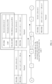
- FIG. 7 is a flowchart of processing performed by an ingress node in an IPv4 network according to an embodiment of this application.
- the processing process includes the following steps.
- S701 After receiving a packet from an IPv6 network, the ingress node in the IPv4 network updates a segment left (Segment Left, SL) field and an IPv6 destination address (IPv6 DA) field in the IPv6 packet.
- Segment Left, SL Segment Left
- IPv6 DA IPv6 destination address
- the ingress node is not the destination node.
- a tunnel technology may be used for traversal. Different tunnel technologies have different encapsulation manners. That is, different tunnel encapsulation types may be used when the packet is encapsulated.
- the tunnel encapsulation type may be specified in the traversal indication information.
- the traversal indication information indicates that an NVO3 tunnel encapsulation type is used.
- NVO3 tunnel encapsulation type When the Network Virtualization over Layer 3 (NVO3) tunnel encapsulation type is used, the IPv6 packet may traverse the IPv4 network through an overlay network, for example, a Layer 2 tenant network. An overlay tunnel is established between the ingress node and the egress node in the IPv4 network, and the IPv6 packet completes traversal by using the overlay tunnel.
- NVO3 Network Virtualization over Layer 3
- the ingress node may further encapsulate a UDP header at the outer layer of the packet, and set an overlay header and a UDP destination port that corresponds to an overlay protocol header.
- the process may specifically include the following steps.
- Both the process of encapsulating the UDP header and the process of encapsulating the overlay header may be implemented by using an existing implementation, and details are not described herein.
- the egress node After the packet reaches the egress node, the egress node decapsulates the packet and exposes the original IPv6 packet. Then, the egress node continues to perform forwarding in the IPv6 network according to an existing IPv6 or SRv6 forwarding process until the packet reaches the destination node.
- the egress node R5 decapsulates the packet and continues to forward the packet to a next node R6 until the packet reaches a destination node R7.
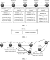
- FIG. 8 is a diagram of an application scenario in which a packet traverses an IPv4 network by using a VXLAN-GPE according to an embodiment of this application.
- the following describes, by using FIG. 9 , a processing process in the application scenario shown in FIG. 8 .
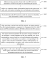
- FIG. 9 is a flowchart of a method in which an SRv6 packet traverses an IPv4 network by using a VXLAN-GPE according to an embodiment of this application. The method includes the following steps.
- the new type of SID is extended to carry the traversal indication information, so that the head node not only has a capability of selecting the path in the IPv6 network (where the capability is implemented by using the SRv6 SRH), but also has a capability of selecting the exit of the tunnel in the IPv4 network. Therefore, the end-to-end path is controlled.
- the new type of SID extended in this embodiment of this application can implement not only controlling on the end-to-end path by the head node, but also copying between the IPv6 packet and the IPv4 packet.
- the following uses an example, in which an in-situ Operation, Administration, and Maintenance in-situ Operation, Administration, and Maintenance (IOAM) header (where IOAM is sometimes also referred to as in-band Operation, Administration, and Maintenance in-band OAM, and this is not limited in this embodiment of this application) and/or a priority is copied, for description.
- IOAM in-situ Operation, Administration, and Maintenance in-situ Operation, Administration, and Maintenance
- the IPv6 packet carries the IOAM header.
- the packet forwarding process in step S902 information needs to be further collected along the path based on an indication of the IOAM header.
- the edge node (the node 2) further copies the IOAM header in the IPv6 extension header to the IPv4 extension header or the overlay header.
- information is further collected along the path based on the indication of the IOAM header.
- the IOAM header, in the IPv4 extension header or the overlay header is further copied to the IPv6 extension header, and in the forwarding process in step S907, information is further collected along the path based on the indication of the IOAM header.
- an IPv6 packet carries an APP-ID.
- the APP-ID may be mapped to different SR policies to ensure service level agreements Service Level Agreements (SLAs) of different applications.
- SLAs Service Level Agreements
- the APP-ID can be mapped to a DSCP field in an IPv4 packet header, to indicate a forwarding priority in the IPv4 domain.
- an ingress node in the IPv4 network may set, in the DSCP field in the IPv4 packet header, APP-ID information carried in an IPv6 Hop-by-hop header or an SRH header.
- a priority is matched based on DSCP.
- nodes in this embodiment of this application are network devices, and may be switches, routers, or the like in a network.
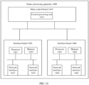
- FIG. 14 is a schematic diagram of a structure of a packet processing apparatus according to an embodiment of this application.
- the packet processing apparatus may be the node in the first network or the ingress node in the second network in any one of the foregoing embodiments.
- the node in the first network in the embodiments of this application is a head node of an SR tunnel established in the first network.
- the packet processing apparatus 1400 may be a switch, a router, or another network device that forwards a packet.
- the packet processing apparatus 1400 includes a main control board 1410, an interface board 1430, and an interface board 1440. When there are a plurality of interface boards, a switching board (not shown in the figure) may be included. The switching board is configured to exchange data between the interface boards (where the interface board is also referred to as a line card or a service board).
- the main control board 1410 is configured to complete functions such as system management, device maintenance, and protocol processing.
- the interface boards 1430 and 1440 are configured to provide various service interfaces (for example, a POS interface, a GE interface, and an ATM interface), and forward a packet.
- the main control board 1410 mainly includes three types of function units: a system management and control unit, a system clock unit, and a system maintenance unit.
- the main control board 1410, the interface board 1430, and the interface board 1440 are connected to a system backboard by using a system bus to implement interworking.
- the interface board 1430 includes one or more processors 1431.
- the processor 1431 is configured to control and manage the interface board, communicate with a central processing unit on the main control board, and forward a packet.
- a memory 1432 on the interface board 1430 is configured to store a forwarding entry, and the processor 1431 forwards a packet by searching the forwarding entry stored in the memory 1432.
- the interface board 1430 includes one or more network interfaces 1433, configured to receive a probe packet sent by a previous-hop network node, and send a processed probe packet to a next-hop network node based on an indication of the processor 1431.
- network interfaces 1433 configured to receive a probe packet sent by a previous-hop network node, and send a processed probe packet to a next-hop network node based on an indication of the processor 1431.
- steps S601 and S603 in the embodiment shown in FIG. 6 steps S701 and S703 in the embodiment shown in FIG. 7 , or steps S902, S905, and S907 in the embodiment shown in FIG. 9 .
- the processor 1431 is configured to perform processing steps and functions of the node in the first network or the ingress node in the second network described in the foregoing method embodiments. For details, refer to steps S601 and S602 in the embodiment shown in FIG. 6 , steps S701 and S702 in the embodiment shown in FIG. 7 , or steps S901 to S908 in the embodiment shown in FIG. 9 . Details are not described herein one by one again.
- this embodiment includes a plurality of interface boards, and uses a distributed forwarding mechanism.
- operations on the interface board 1440 are basically similar to operations on the interface board 1430. For brevity, details are not described again.
- the processor 1431 on the interface board 1430 and/or the processor 1441 in FIG. 14 may be dedicated hardware or a chip, for example, a network processor or an application-specific integrated circuit (application-specific integrated circuit), to implement the foregoing functions.
- This implementation is generally referred to as a manner of using dedicated hardware or a chip for processing on a forwarding plane.
- the processor 1431 and/or 1441 may alternatively be a general-purpose processor, for example, a general-purpose CPU, to implement the foregoing described functions.
- the general-purpose CPU refer to descriptions in embodiments shown in FIG. 18 and FIG. 19 .
- main control boards there may be one or more main control boards, and when there are a plurality of main control boards, the main control boards may include an active main control board and a standby main control board.
- main control boards There may be one or more interface boards, and a device having a stronger data processing capability provides more interface boards. If there are a plurality of interface boards, the plurality of interface boards can communicate with each other by using one or more switching boards, and the plurality of interface boards can jointly implement load sharing and redundancy backup.
- the device may not need the switching board, and the interface board provides a function of processing service data of an entire system.
- the device includes a plurality of interface boards.
- Data exchange between the plurality of interface boards may be implemented by using a switching board, and the plurality of interface boards can provide a large-capacity data exchange and processing capability. Therefore, a data access and processing capability of a network device in the distributed architecture is better than that of a device in the centralized architecture.
- a specific architecture that is to be used depends on a specific networking deployment scenario. This is not limited herein.
- the memory 1432 may be a read-only memory (read-only memory, ROM), another type of static storage device that can store static information and instructions, a random access memory (random access memory, RAM), or another type of dynamic storage device that can store information and instructions, or may be an electrically erasable programmable read-only memory (electrically erasable programmable read-only memory, EEPROM), a compact disc read-only memory (compact disc read-only memory, CD-ROM) or another compact disc storage, an optical disc storage (including a compact optical disc, a laser disc, an optical disc, a digital versatile disc, a Blu-ray disc, and the like), a magnetic disk storage medium or another magnetic storage device, or any other medium that can be used to carry or store expected program code in a form of an instruction or a data structure and that can be accessed by a computer.
- the memory is not limited thereto.
- the memory 1432 may exist independently, and is connected to the processor 1431 by using a communication bus.
- the memory 1432
- the memory 1432 is configured to store program code, and execution is controlled by the processor 1431, to perform the packet processing method provided in the foregoing embodiment.
- the processor 1431 is configured to execute the program code stored in the memory 1432.
- the program code may include one or more software modules.
- the one or more software modules may be a software module provided in an embodiment in any one of FIG. 16 or FIG. 17 .
- the network interface 1433 may be an apparatus that uses any transceiver, and is configured to communicate with another device or a communication network, for example, the Ethernet, a radio access network (radio access network, RAN), or a wireless local area network (wireless local area network, WLAN).
- a radio access network radio access network, RAN
- a wireless local area network wireless local area network, WLAN
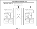
- FIG. 15 is another schematic diagram of a structure of a packet processing apparatus according to an embodiment of this application.
- the packet processing apparatus may be the node in the first network or the ingress node in the second network in any one of the foregoing embodiments.
- the node in the first network in the embodiments of this application is a head node of an SR tunnel established in the first network.
- the packet processing apparatus 1500 may be a switch, a router, or another network device that forwards a packet.
- the packet processing apparatus 1500 includes a main control board 1510, an interface board 1530, a switching board 1520, and an interface board 1540.
- the main control board 1510 is configured to complete functions such as system management, device maintenance, and protocol processing.
- the switching board 1520 is configured to exchange data between the forwarding boards (the forwarding board is also referred to as a line card or a service board).
- the interface boards 1530 and 1540 are configured to provide various service interfaces (for example, a POS interface, a GE interface, and an ATM interface), and forward a data packet.
- a control plane includes management and control units on the main control board 1510 and management and control units on the interface board 1530 and the interface board 1540.
- the main control board 1510 mainly includes three types of function units: a system management and control unit, a system clock unit, and a system maintenance unit.
- the main control board 1510, the interface boards 1530 and 1540, and the switching board 1520 are connected to a system backboard by using a system bus to implement interworking.
- a central processing unit 1531 on the interface board 1530 is configured to control and manage the interface board, and communicate with a central processing unit on a main control board.
- a forwarding entry memory 1534 on the interface board 1530 is configured to store a forwarding entry, and a network processor 1532 forwards a packet by searching the forwarding entry stored in the forwarding entry memory 1534.
- the interface board 1530 includes one or more network interfaces 1533, configured to receive a probe packet sent by a previous-hop network node, and send a processed probe packet to a next-hop network node based on an indication of the processor 1531.
- network interfaces 1533 configured to receive a probe packet sent by a previous-hop network node, and send a processed probe packet to a next-hop network node based on an indication of the processor 1531.
- steps S601 and S603 in the embodiment shown in FIG. 6 steps S701 and S703 in the embodiment shown in FIG. 7 , or steps S902, S905, and S907 in the embodiment shown in FIG. 9 . Details are not described herein one by one again.
- the processor 1532 is configured to perform processing steps and functions of the node in the first network or the ingress node in the second network described in the foregoing method embodiments. For details, refer to steps S601 and S602 in the embodiment shown in FIG. 6 , steps S701 and S702 in the embodiment shown in FIG. 7 , or steps S901 to S908 in the embodiment shown in FIG. 9 . Details are not described herein one by one again.
- this embodiment includes a plurality of interface boards, and uses a distributed forwarding mechanism.
- operations on the interface board 1540 are basically similar to operations on the interface board 1530.
- functions of the network processors 1532 and 1542 in FIG. 15 may be replaced with that of an application-specific integrated circuit (application-specific integrated circuit).
- main control boards there may be one or more main control boards, and when there are a plurality of main control boards, the main control boards may include an active main control board and a standby main control board.
- main control boards There may be one or more interface boards, and a device having a stronger data processing capability provides more interface boards.
- the device may not need the switching board, and the interface board provides a function of processing service data of an entire system.
- the device may include at least one switching board, and data exchange between a plurality of interface boards is implemented by using the switching board, to provide a large-capacity data exchange and processing capability. Therefore, a data access and processing capability of a network device in the distributed architecture is better than that of a device in the centralized architecture.
- a specific architecture that is to be used depends on a specific networking deployment scenario. This is not limited herein.
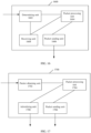
- An embodiment of this application further provides a packet processing apparatus 1600.
- the apparatus may be used in a node in a network.
- the node is a head node of an SR tunnel established in the network.
- the node may implement a function of the head node of the SR tunnel shown in FIG. 6 or FIG. 9 .
- the packet processing apparatus includes a determining unit 1602, a packet processing unit 1604, and a packet sending unit 1606.
- the determining unit 1602 is configured to perform step S601 in the embodiment shown in FIG. 6 , that is, determine an end-to-end transmission path for a packet, where the transmission path includes a transmission path in a first network and a path traversing a second network.
- the packet processing unit 1604 is configured to perform step S602 in the embodiment shown in FIG. 6 , that is, add end-to-end path information to the packet based on the determined transmission path, where the path information includes traversal indication information, and the traversal indication information indicates an egress node of the packet in the second network.
- the packet sending unit 1606 is specifically configured to send the packet processed by the packet processing unit 1604. Specifically, the packet sending unit 1606 may send, to an ingress node in the second network through the first network, the packet to which the traversal indication information is added, to indicate the ingress node in the second network to encapsulate and transmit the packet based on the egress node that is specified in the traversal indication information and that is located in the second network.
- the packet sending unit 1606 may send, to an ingress node in the second network through the first network, the packet to which the traversal indication information is added, to indicate the ingress node in the second network to encapsulate and transmit the packet based on the egress node that is specified in the traversal indication information and that is located in the second network.
- the packet processing apparatus 1600 may further include a receiving unit 1608, configured to receive at least one SID advertised by the ingress node in the second network, where different SIDs advertised by the ingress node carry different traversal indication information.
- the packet processing unit 1604 uses an SID corresponding to the path that is determined by the determining unit based on the traversal indication information and that traverses the second network as the SID of the ingress node in the second network, and adds the SID to the end-to-end path information.
- An embodiment of this application further provides a packet processing apparatus 1700.
- the apparatus may be used in an edge node in a network, and the node may implement a function of the ingress node shown in FIG. 7 or FIG. 9 .
- An embodiment of this application provides a packet processing apparatus 1800.
- the packet processing apparatus 1800 may implement the function of the head node of the SR tunnel in the embodiments shown in FIG. 6 and FIG. 9 .
- the packet processing apparatus includes at least one processor 1802 and at least one communication interface 1804.
Landscapes
- Engineering & Computer Science (AREA)
- Computer Networks & Wireless Communication (AREA)
- Signal Processing (AREA)
- Data Exchanges In Wide-Area Networks (AREA)
Claims (15)
- Paketverarbeitungsverfahren, das umfasst:Bestimmen (S601), durch einen Knoten in einem ersten Netzwerk, wo der Knoten in dem ersten Netzwerk ein Kopfknoten eines Segmentrouting(SR)-Tunnels ist, der in dem ersten Netzwerk eingerichtet ist, eines Übertragungspfads für ein Paket, wobei der Übertragungspfad einen Pfad in dem ersten Netzwerk und einen Pfad, der ein zweites Netzwerk durchquert, umfasst;Hinzufügen (S602), durch den Knoten in dem ersten Netzwerk, von Pfadinformationen zu dem Paket basierend auf dem bestimmten Übertragungspfad, wobei die Pfadinformationen Durchquerungsanzeigeinformationen umfassen und die Durchquerungsanzeigeinformationen einen Eingangsknoten und einen Ausgangsknoten des Pakets in dem zweiten Netzwerk anzeigen; undSenden (S603), durch den Knoten in dem ersten Netzwerk basierend auf den Pfadinformationen, des Pakets an einen Eingangsknoten in dem zweiten Netzwerk mittels des ersten Netzwerks, um dem Eingangsknoten in dem zweiten Netzwerk anzuzeigen, das Paket durch Verwenden des Ausgangsknotens, der in den Durchquerungsanzeigeinformationen angegebenen wird, zu übertragen, wobei, nach einem Empfangen des Pakets, der Eingangsknoten in dem zweiten Netzwerk das Paket basierend auf den Durchquerungsanzeigeinformationen in dem Paket einkapselt (S702), um ein Format des Pakets in ein Format, das durch das zweite Netzwerk unterstützt wird, zu ändern; wobeidas erste Netzwerk ein IPv6-Netzwerk ist, das zweite Netzwerk ein IPv4-Netzwerk ist und das Paket ein IPv6-Paket ist.
- Verfahren nach Anspruch 1, wobei die Pfadinformationen eine Segmentkennung (SID) eines Zwischenknotens auf dem Pfad in dem ersten Netzwerk und eine SID des Eingangsknotens in dem zweiten Netzwerk umfassen und die Durchquerungsanzeigeinformationen in der SID des Eingangsknotens in dem zweiten Netzwerk enthalten sind.
- Verfahren nach Anspruch 2, wobei, vor dem Bestimmen eines Übertragungspfads, das Verfahren ferner umfasst:Empfangen, durch den Knoten in dem ersten Netzwerk, von mindestens einer SID, die durch den Eingangsknoten in dem zweiten Netzwerk angekündigt wird, wobei unterschiedliche SIDs, die durch den Eingangsknoten angekündigt werden, unterschiedliche Durchquerungsanzeigeinformationen tragen; undwenn die Pfadinformationen zu dem Paket hinzugefügt werden, Verwenden, durch den Knoten in dem ersten Netzwerk, einer SID, die dem Pfad entspricht, der durch den Knoten in dem ersten Netzwerk basierend auf den Durchquerungsanzeigeinformationen bestimmt wird und der das zweite Netzwerk durchquert, als die SID des Eingangsknotens in dem zweiten Netzwerk, und Hinzufügen der SID zu den Pfadinformationen.
- Verfahren nach einem der Ansprüche 1 bis 3, wobei dieDurchquerungsanzeigeinformationen ferner einen Tunneleinkapselungstyp, der verwendet wird, wenn das Paket das zweite Netzwerk durchquert, anzeigen; undnachdem das Paket den Eingangsknoten in dem zweiten Netzwerk erreicht, dem Eingangsknoten durch die Durchquerungsanzeigeinformationen angezeigt wird, das Paket basierend auf dem Tunneleinkapselungstyp einzukapseln.
- Verfahren nach Anspruch 4, wobei es sich bei dem Tunneleinkapselungstyp um eine Netzwerkvirtualisierung über Schicht 3 (NVO3) handelt.
- Verfahren nach Anspruch 5, wobei die Durchquerungsanzeigeinformationen ferner einen Inhalt anzeigen, der während einer Einkapselung kopiert werden muss; und
nachdem das Paket den Eingangsknoten in dem zweiten Netzwerk erreicht, dem Eingangsknoten durch die Durchquerungsanzeigeinformationen angezeigt wird, wenn das Paket eingekapselt wird, den Inhalt, der kopiert werden muss, von einem Paketkopfbereich eines Protokolls, das durch das erste Netzwerk unterstützt wird, auf einen Paketkopfbereich eines Protokolls, das durch das zweite Netzwerk unterstützt wird, nachdem das Paket eingekapselt wird, zu kopieren. - Verfahren nach einem der Ansprüche 1 bis 6, wobei das erste Netzwerk ein IPv6-Netzwerk ist und das zweite Netzwerk ein IPv4-Netzwerk ist.
- Paketverarbeitungsverfahren, das umfasst:Empfangen (S701), durch einen Eingangsknoten in einem zweiten Netzwerk, eines Pakets von einem ersten Netzwerk, wobei das Paket Durchquerungsanzeigeinformationen trägt und die Durchquerungsanzeigeinformationen einen Eingangsknoten und einen Ausgangsknoten des Pakets in dem zweiten Netzwerk anzeigen;Einkapseln (S701), durch den Eingangsknoten, des Pakets basierend auf den Durchquerungsanzeigeinformationen, um ein Format des Pakets in ein Format, das durch das zweite Netzwerk unterstützt wird, zu ändern, wobei eine Zieladresse des eingekapselten Pakets der Ausgangsknoten, der in den Durchquerungsanzeigeinformationen angezeigt wird, ist; undRouten (S703), durch den Eingangsknoten, des eingekapselten Pakets an den Ausgangsknoten; wobeidie Durchquerungsanzeigeinformationen zu dem Paket durch einen Kopfknoten eines Segmentrouting(SR)-Tunnels hinzugefügt werden, der in dem ersten Netzwerk basierend auf einem Übertragungspfad für das Paket, der durch den Kopfknoten bestimmt wird, eingerichtet wird, wobei der Übertragungspfad einen Pfad in dem ersten Netzwerk und einen Pfad, der das zweite Netzwerk durchquert, umfasst;wobeidas erste Netzwerk ein IPv6-Netzwerk ist, das zweite Netzwerk ein IPv4-Netzwerk ist und das Paket ein IPv6-Paket ist.
- Verfahren nach Anspruch 8, wobei das Paket eine Segmentkennung (SID) des Eingangsknotens trägt und die Durchquerungsanzeigeinformationen in der SID des Eingangsknotens getragen werden.
- Verfahren nach Anspruch 8 oder 9, wobei das erste Netzwerk ein IPv6-Netzwerk ist und das zweite Netzwerk ein IPv4-Netzwerk ist; und das Einkapseln (S702), durch den Eingangsknoten, des Pakets basierend auf den Durchquerungsanzeigeinformationen, um ein Format des Pakets in ein Format, das durch das zweite Netzwerk unterstützt wird, zu ändern, umfasst:
Einkapseln, durch den Eingangsknoten, eines IPv4-Paketkopfbereichs außerhalb des Pakets, Festlegen einer Quelladresse des IPv4-Paketkopfbereichs als eine IPv4-Adresse des Eingangsknotens oder als eine IPv4-Adresse einer Schnittstelle, die dem Eingangsknoten entspricht, und Festlegen einer Zieladresse des IPv4-Paketkopfbereichs als eine IPv4-Adresse des Ausgangsknotens in den Durchquerungsanzeigeinformationen oder als eine IPv4-Adresse einer Schnittstelle, die dem Ausgangsknoten entspricht. - Verfahren nach einem der Ansprüche 8 bis 10, wobei dieDurchquerungsanzeigeinformationen ferner einen Tunneleinkapselungstyp anzeigen, der verwendet wird, wenn das Paket das zweite Netzwerk durchquert; unddas Einkapseln (S702), durch den Eingangsknoten, des Pakets basierend auf den Durchquerungsanzeigeinformationen, um ein Format des Pakets in ein Format, das durch das zweite Netzwerk unterstützt wird, zu ändern, ferner umfasst:
Einrichten, durch den Eingangsknoten, eines Übertragungstunnels zu dem Ausgangsknoten basierend auf dem Tunneleinkapselungstyp, der in den Durchquerungsanzeigeinformationen angezeigt wird. - Verfahren nach Anspruch 11, wobei es sich bei dem Tunneleinkapselungstyp, der in den Durchquerungsanzeigeinformationen angezeigt wird, um die Netzwerkvirtualisierung über Schicht 3 (NVO3) handelt.
- Verfahren nach einem der Ansprüche 8 bis 12, wobei dieDurchquerungsanzeigeinformationen ferner den Inhalt anzeigen, der während der Einkapselung kopiert werden muss; undwenn der Eingangsknoten das Paket einkapselt, um das Format des Pakets in das Format, das durch das zweite Netzwerk unterstützt wird, zu ändern, das Verfahren ferner umfasst:
Kopieren, durch den Eingangsknoten auf den IPv4-Paketkopfbereich, des Inhalts, der in den Durchquerungsanzeigeinformationen angezeigt wird und der kopiert werden muss. - Paketverarbeitungseinrichtung (1400, 1500), wobei es sich bei der Einrichtung um einen Knoten in einem ersten Netzwerk handelt, wobei der Knoten in dem ersten Netzwerk ein Kopfknoten eines Segmentrouting(SR)-Tunnels, der in dem ersten Netzwerk eingerichtet wird, ist und wobei die Einrichtung (1400, 1500) konfiguriert ist, um das Verfahren nach einem der Ansprüche 1 bis 7 zu implementieren.
- Paketverarbeitungseinrichtung (1400, 1500), wobei es sich bei der Einrichtung um einen Eingangsknoten in einem zweiten Netzwerk handelt und wobei die Einrichtung konfiguriert ist, um das Verfahren nach einem der Ansprüche 8 bis 13 zu implementieren.
Applications Claiming Priority (3)
| Application Number | Priority Date | Filing Date | Title |
|---|---|---|---|
| CN201911084038 | 2019-11-07 | ||
| CN201911426082.5A CN112787923B (zh) | 2019-11-07 | 2019-12-31 | 一种报文的处理方法,装置和系统 |
| PCT/CN2020/105005 WO2021088433A1 (zh) | 2019-11-07 | 2020-07-28 | 一种报文的处理方法,装置和系统 |
Publications (3)
| Publication Number | Publication Date |
|---|---|
| EP4040738A1 EP4040738A1 (de) | 2022-08-10 |
| EP4040738A4 EP4040738A4 (de) | 2022-11-02 |
| EP4040738B1 true EP4040738B1 (de) | 2025-03-19 |
Family
ID=75749954
Family Applications (1)
| Application Number | Title | Priority Date | Filing Date |
|---|---|---|---|
| EP20884921.6A Active EP4040738B1 (de) | 2019-11-07 | 2020-07-28 | Nachrichtenverarbeitungsverfahren, -vorrichtung und -system |
Country Status (4)
| Country | Link |
|---|---|
| US (1) | US12166667B2 (de) |
| EP (1) | EP4040738B1 (de) |
| CN (1) | CN112787923B (de) |
| WO (1) | WO2021088433A1 (de) |
Families Citing this family (12)
| Publication number | Priority date | Publication date | Assignee | Title |
|---|---|---|---|---|
| CN112491718B (zh) * | 2020-08-31 | 2025-01-28 | 中兴通讯股份有限公司 | 报文头的处理方法及装置、存储介质、电子装置 |
| CN113973074B (zh) * | 2021-10-26 | 2022-12-20 | 新华三信息安全技术有限公司 | 一种报文处理方法、装置、电子设备及介质 |
| CN114221904B (zh) * | 2021-12-15 | 2023-08-18 | 锐捷网络股份有限公司 | 一种报文转发方法、装置及系统 |
| CN116366395A (zh) * | 2021-12-28 | 2023-06-30 | 中国移动通信有限公司研究院 | 一种报文传输的方法及装置 |
| CN116418739B (zh) * | 2021-12-29 | 2026-01-06 | 中国移动通信有限公司研究院 | 一种报文处理方法、装置及网络设备 |
| CN116846827A (zh) * | 2022-03-24 | 2023-10-03 | 中国移动通信有限公司研究院 | 报文封装及传输方法、装置、网络节点及存储介质 |
| CN116938787A (zh) * | 2022-04-06 | 2023-10-24 | 中兴通讯股份有限公司 | 一种报文转发方法、装置、存储介质及电子装置 |
| CN115242885B (zh) * | 2022-07-15 | 2023-10-13 | 天翼云科技有限公司 | 云数据中心系统、数据报文传输方法、设备和介质 |
| CN118118436A (zh) * | 2022-11-30 | 2024-05-31 | 华为技术有限公司 | 一种通信方法及装置 |
| CN116192761B (zh) * | 2023-02-27 | 2025-08-26 | 阿里巴巴(中国)有限公司 | 报文转发方法、转发层设备、系统、电子设备及存储介质 |
| CN117914973A (zh) * | 2024-01-05 | 2024-04-19 | 凌锐蓝信科技(北京)有限公司 | 报文转发方法、装置、网络设备及存储介质 |
| CN119211113A (zh) * | 2024-09-20 | 2024-12-27 | 武汉烽火技术服务有限公司 | 一种SRv6中间节点恢复方法、系统、设备及存储介质 |
Family Cites Families (20)
| Publication number | Priority date | Publication date | Assignee | Title |
|---|---|---|---|---|
| US7609691B2 (en) * | 2005-03-21 | 2009-10-27 | Cisco Technology, Inc. | Method and system for automatically interconnecting IPv4 networks across an IPv6 network |
| KR101221594B1 (ko) * | 2005-10-24 | 2013-01-14 | 삼성전자주식회사 | 아이피 터널링 경로 상의 터널 시그널링을 수행하는 방법및 장치 |
| CN101247308B (zh) * | 2007-02-13 | 2011-04-27 | 上海亿人通信终端有限公司 | 基于网络处理器实现IPv6穿越IPv4的隧道报文处理方法 |
| CN101094155B (zh) * | 2007-08-02 | 2010-11-03 | 杭州华三通信技术有限公司 | 建立IPv6隧道的方法、IPv6隧道通信方法及IPv4边缘设备 |
| CN101252524A (zh) * | 2008-04-08 | 2008-08-27 | 华为技术有限公司 | 一种报文传输的方法、系统和装置 |
| CN102447617A (zh) * | 2010-10-09 | 2012-05-09 | 华为技术有限公司 | IPv4网络中传输IPv6报文的方法、终端及网关 |
| CN102098353B (zh) * | 2011-01-31 | 2013-04-17 | 北京邮电大学 | 基于分布式哈希表DHT实现IPv4和IPv6互通的系统和方法 |
| CN102572007B (zh) * | 2011-12-06 | 2015-05-27 | 华为技术有限公司 | 跨越IPv4网络转发IPv6组播报文的方法和边缘设备 |
| CN102970386B (zh) * | 2012-11-15 | 2016-01-13 | 杭州迪普科技有限公司 | 一种实现IPv6报文穿越IPv4网络的方法和设备 |
| US9178816B1 (en) * | 2013-09-27 | 2015-11-03 | Juniper Networks, Inc. | Control plane messaging in all-active multi-homed ethernet virtual private networks |
| CN103533100B (zh) * | 2013-10-15 | 2016-09-21 | 中国联合网络通信集团有限公司 | 报文传输方法和节点设备 |
| US10439993B2 (en) * | 2015-08-19 | 2019-10-08 | Cisco Technology, Inc. | Mapping system assisted key refreshing |
| US10270690B2 (en) * | 2016-02-29 | 2019-04-23 | Cisco Technology, Inc. | System and method for dataplane-signaled packet capture in IPV6 environment |
| CN107517157B (zh) * | 2016-06-16 | 2020-09-11 | 华为技术有限公司 | 一种路径确定方法、装置和系统 |
| US10320664B2 (en) * | 2016-07-21 | 2019-06-11 | Cisco Technology, Inc. | Cloud overlay for operations administration and management |
| CN109995655A (zh) * | 2018-01-03 | 2019-07-09 | 中兴通讯股份有限公司 | 一种实现无缝最优跨域路径的方法及装置 |
| US10938685B2 (en) * | 2018-07-24 | 2021-03-02 | Cisco Technology, Inc. | Secure traffic visibility and analytics for encrypted traffic |
| CN109379359B (zh) * | 2018-10-19 | 2021-09-07 | 苏州盛科通信股份有限公司 | SRv6数据包的处理方法和装置 |
| US11134002B2 (en) * | 2018-10-22 | 2021-09-28 | Cisco Technology, Inc. | Packet network interworking including segment routing |
| CN109495385B (zh) * | 2018-12-04 | 2021-06-18 | 安徽皖兴通信息技术有限公司 | 一种实现非连续分段路由域的网络流量调度方法 |
-
2019
- 2019-12-31 CN CN201911426082.5A patent/CN112787923B/zh active Active
-
2020
- 2020-07-28 WO PCT/CN2020/105005 patent/WO2021088433A1/zh not_active Ceased
- 2020-07-28 EP EP20884921.6A patent/EP4040738B1/de active Active
-
2022
- 2022-05-06 US US17/738,765 patent/US12166667B2/en active Active
Also Published As
| Publication number | Publication date |
|---|---|
| CN112787923B (zh) | 2024-06-21 |
| WO2021088433A1 (zh) | 2021-05-14 |
| EP4040738A1 (de) | 2022-08-10 |
| CN112787923A (zh) | 2021-05-11 |
| EP4040738A4 (de) | 2022-11-02 |
| US12166667B2 (en) | 2024-12-10 |
| US20220263751A1 (en) | 2022-08-18 |
Similar Documents
| Publication | Publication Date | Title |
|---|---|---|
| EP4040738B1 (de) | Nachrichtenverarbeitungsverfahren, -vorrichtung und -system | |
| JP7419510B2 (ja) | Bier転送項目構築方法、装置、およびシステム | |
| US12368669B2 (en) | Packet sending method, device, and system | |
| EP3471347B1 (de) | Vxlan-paketverarbeitungsverfahren, -vorrichtung und -system | |
| EP3713162A1 (de) | Verfahren und vorrichtung zur routenverarbeitung und datenübertragungsverfahren und vorrichtung | |
| EP3944569A1 (de) | Datenverarbeitungsverfahren auf basis von srv6 und zugehörige netzwerkvorrichtung | |
| WO2021135420A1 (zh) | 业务链的故障保护方法、装置、设备、系统及存储介质 | |
| CN112087386B (zh) | 一种报文处理的方法、设备和系统 | |
| US20140351812A1 (en) | Recording medium, management device, and network system | |
| JP2023514630A (ja) | 転送エントリ生成方法、パケット送信方法、ネットワークデバイス、およびシステム | |
| JP7547606B2 (ja) | ルート告知方法および関連デバイス | |
| EP4009608B1 (de) | Segment-routing-basiertes datenübertragungsverfahren und -gerät | |
| US12531763B2 (en) | Route advertisement method and related device | |
| US20240297844A1 (en) | Packet Processing Method and Apparatus, and Device | |
| CN113542111A (zh) | 一种报文转发方法及网络设备 | |
| WO2022007550A1 (zh) | 一种负载均衡方法、装置、网络设备及系统 | |
| JP2023532737A (ja) | パケット処理方法およびネットワークデバイス | |
| JP7609382B2 (ja) | ルートアドバタイズメント方法、装置、及びシステム | |
| CN113542112A (zh) | 一种报文转发方法及网络设备 | |
| WO2022267969A1 (zh) | 一种信息传输方法及相关设备 | |
| US20250055791A1 (en) | Packet processing method, apparatus, and system | |
| JP2024545790A (ja) | パケット送信方法、ネットワークデバイス、およびシステム | |
| EP4664851A1 (de) | Paketweiterleitungsverfahren, -vorrichtung und -system | |
| US20250097139A1 (en) | Packet sending method, network device, and system | |
| US20240031283A1 (en) | Communication method and apparatus |
Legal Events
| Date | Code | Title | Description |
|---|---|---|---|
| STAA | Information on the status of an ep patent application or granted ep patent |
Free format text: STATUS: THE INTERNATIONAL PUBLICATION HAS BEEN MADE |
|
| PUAI | Public reference made under article 153(3) epc to a published international application that has entered the european phase |
Free format text: ORIGINAL CODE: 0009012 |
|
| STAA | Information on the status of an ep patent application or granted ep patent |
Free format text: STATUS: REQUEST FOR EXAMINATION WAS MADE |
|
| 17P | Request for examination filed |
Effective date: 20220504 |
|
| AK | Designated contracting states |
Kind code of ref document: A1 Designated state(s): AL AT BE BG CH CY CZ DE DK EE ES FI FR GB GR HR HU IE IS IT LI LT LU LV MC MK MT NL NO PL PT RO RS SE SI SK SM TR |
|
| A4 | Supplementary search report drawn up and despatched |
Effective date: 20221005 |
|
| RIC1 | Information provided on ipc code assigned before grant |
Ipc: H04L 45/00 20220101ALI20220928BHEP Ipc: H04L 12/46 20060101AFI20220928BHEP |
|
| DAV | Request for validation of the european patent (deleted) | ||
| DAX | Request for extension of the european patent (deleted) | ||
| STAA | Information on the status of an ep patent application or granted ep patent |
Free format text: STATUS: EXAMINATION IS IN PROGRESS |
|
| 17Q | First examination report despatched |
Effective date: 20231017 |
|
| GRAP | Despatch of communication of intention to grant a patent |
Free format text: ORIGINAL CODE: EPIDOSNIGR1 |
|
| STAA | Information on the status of an ep patent application or granted ep patent |
Free format text: STATUS: GRANT OF PATENT IS INTENDED |
|
| RIC1 | Information provided on ipc code assigned before grant |
Ipc: H04L 45/02 20220101ALI20241002BHEP Ipc: H04L 45/00 20220101ALI20241002BHEP Ipc: H04L 12/46 20060101AFI20241002BHEP |
|
| INTG | Intention to grant announced |
Effective date: 20241017 |
|
| GRAS | Grant fee paid |
Free format text: ORIGINAL CODE: EPIDOSNIGR3 |
|
| GRAA | (expected) grant |
Free format text: ORIGINAL CODE: 0009210 |
|
| STAA | Information on the status of an ep patent application or granted ep patent |
Free format text: STATUS: THE PATENT HAS BEEN GRANTED |
|
| AK | Designated contracting states |
Kind code of ref document: B1 Designated state(s): AL AT BE BG CH CY CZ DE DK EE ES FI FR GB GR HR HU IE IS IT LI LT LU LV MC MK MT NL NO PL PT RO RS SE SI SK SM TR |
|
| REG | Reference to a national code |
Ref country code: GB Ref legal event code: FG4D |
|
| REG | Reference to a national code |
Ref country code: CH Ref legal event code: EP |
|
| REG | Reference to a national code |
Ref country code: DE Ref legal event code: R096 Ref document number: 602020048117 Country of ref document: DE |
|
| REG | Reference to a national code |
Ref country code: IE Ref legal event code: FG4D |
|
| PG25 | Lapsed in a contracting state [announced via postgrant information from national office to epo] |
Ref country code: RS Free format text: LAPSE BECAUSE OF FAILURE TO SUBMIT A TRANSLATION OF THE DESCRIPTION OR TO PAY THE FEE WITHIN THE PRESCRIBED TIME-LIMIT Effective date: 20250619 |
|
| PG25 | Lapsed in a contracting state [announced via postgrant information from national office to epo] |
Ref country code: FI Free format text: LAPSE BECAUSE OF FAILURE TO SUBMIT A TRANSLATION OF THE DESCRIPTION OR TO PAY THE FEE WITHIN THE PRESCRIBED TIME-LIMIT Effective date: 20250319 |
|
| REG | Reference to a national code |
Ref country code: LT Ref legal event code: MG9D |
|
| PG25 | Lapsed in a contracting state [announced via postgrant information from national office to epo] |
Ref country code: NO Free format text: LAPSE BECAUSE OF FAILURE TO SUBMIT A TRANSLATION OF THE DESCRIPTION OR TO PAY THE FEE WITHIN THE PRESCRIBED TIME-LIMIT Effective date: 20250619 |
|
| PG25 | Lapsed in a contracting state [announced via postgrant information from national office to epo] |
Ref country code: HR Free format text: LAPSE BECAUSE OF FAILURE TO SUBMIT A TRANSLATION OF THE DESCRIPTION OR TO PAY THE FEE WITHIN THE PRESCRIBED TIME-LIMIT Effective date: 20250319 |
|
| PG25 | Lapsed in a contracting state [announced via postgrant information from national office to epo] |
Ref country code: LV Free format text: LAPSE BECAUSE OF FAILURE TO SUBMIT A TRANSLATION OF THE DESCRIPTION OR TO PAY THE FEE WITHIN THE PRESCRIBED TIME-LIMIT Effective date: 20250319 |
|
| PG25 | Lapsed in a contracting state [announced via postgrant information from national office to epo] |
Ref country code: GR Free format text: LAPSE BECAUSE OF FAILURE TO SUBMIT A TRANSLATION OF THE DESCRIPTION OR TO PAY THE FEE WITHIN THE PRESCRIBED TIME-LIMIT Effective date: 20250620 Ref country code: BG Free format text: LAPSE BECAUSE OF FAILURE TO SUBMIT A TRANSLATION OF THE DESCRIPTION OR TO PAY THE FEE WITHIN THE PRESCRIBED TIME-LIMIT Effective date: 20250319 |
|
| REG | Reference to a national code |
Ref country code: NL Ref legal event code: MP Effective date: 20250319 |
|
| REG | Reference to a national code |
Ref country code: AT Ref legal event code: MK05 Ref document number: 1777889 Country of ref document: AT Kind code of ref document: T Effective date: 20250319 |
|
| PG25 | Lapsed in a contracting state [announced via postgrant information from national office to epo] |
Ref country code: NL Free format text: LAPSE BECAUSE OF FAILURE TO SUBMIT A TRANSLATION OF THE DESCRIPTION OR TO PAY THE FEE WITHIN THE PRESCRIBED TIME-LIMIT Effective date: 20250319 |
|
| PG25 | Lapsed in a contracting state [announced via postgrant information from national office to epo] |
Ref country code: SE Free format text: LAPSE BECAUSE OF FAILURE TO SUBMIT A TRANSLATION OF THE DESCRIPTION OR TO PAY THE FEE WITHIN THE PRESCRIBED TIME-LIMIT Effective date: 20250319 |
|
| PG25 | Lapsed in a contracting state [announced via postgrant information from national office to epo] |
Ref country code: SM Free format text: LAPSE BECAUSE OF FAILURE TO SUBMIT A TRANSLATION OF THE DESCRIPTION OR TO PAY THE FEE WITHIN THE PRESCRIBED TIME-LIMIT Effective date: 20250319 |
|
| PG25 | Lapsed in a contracting state [announced via postgrant information from national office to epo] |
Ref country code: ES Free format text: LAPSE BECAUSE OF FAILURE TO SUBMIT A TRANSLATION OF THE DESCRIPTION OR TO PAY THE FEE WITHIN THE PRESCRIBED TIME-LIMIT Effective date: 20250319 Ref country code: PT Free format text: LAPSE BECAUSE OF FAILURE TO SUBMIT A TRANSLATION OF THE DESCRIPTION OR TO PAY THE FEE WITHIN THE PRESCRIBED TIME-LIMIT Effective date: 20250721 |
|
| PGFP | Annual fee paid to national office [announced via postgrant information from national office to epo] |
Ref country code: DE Payment date: 20250604 Year of fee payment: 6 |
|
| PG25 | Lapsed in a contracting state [announced via postgrant information from national office to epo] |
Ref country code: IT Free format text: LAPSE BECAUSE OF FAILURE TO SUBMIT A TRANSLATION OF THE DESCRIPTION OR TO PAY THE FEE WITHIN THE PRESCRIBED TIME-LIMIT Effective date: 20250319 Ref country code: PL Free format text: LAPSE BECAUSE OF FAILURE TO SUBMIT A TRANSLATION OF THE DESCRIPTION OR TO PAY THE FEE WITHIN THE PRESCRIBED TIME-LIMIT Effective date: 20250319 |
|
| PG25 | Lapsed in a contracting state [announced via postgrant information from national office to epo] |
Ref country code: AT Free format text: LAPSE BECAUSE OF FAILURE TO SUBMIT A TRANSLATION OF THE DESCRIPTION OR TO PAY THE FEE WITHIN THE PRESCRIBED TIME-LIMIT Effective date: 20250319 |
|
| PG25 | Lapsed in a contracting state [announced via postgrant information from national office to epo] |
Ref country code: CZ Free format text: LAPSE BECAUSE OF FAILURE TO SUBMIT A TRANSLATION OF THE DESCRIPTION OR TO PAY THE FEE WITHIN THE PRESCRIBED TIME-LIMIT Effective date: 20250319 Ref country code: EE Free format text: LAPSE BECAUSE OF FAILURE TO SUBMIT A TRANSLATION OF THE DESCRIPTION OR TO PAY THE FEE WITHIN THE PRESCRIBED TIME-LIMIT Effective date: 20250319 |
|
| PG25 | Lapsed in a contracting state [announced via postgrant information from national office to epo] |
Ref country code: RO Free format text: LAPSE BECAUSE OF FAILURE TO SUBMIT A TRANSLATION OF THE DESCRIPTION OR TO PAY THE FEE WITHIN THE PRESCRIBED TIME-LIMIT Effective date: 20250319 |
|
| PG25 | Lapsed in a contracting state [announced via postgrant information from national office to epo] |
Ref country code: SK Free format text: LAPSE BECAUSE OF FAILURE TO SUBMIT A TRANSLATION OF THE DESCRIPTION OR TO PAY THE FEE WITHIN THE PRESCRIBED TIME-LIMIT Effective date: 20250319 |
|
| PG25 | Lapsed in a contracting state [announced via postgrant information from national office to epo] |
Ref country code: IS Free format text: LAPSE BECAUSE OF FAILURE TO SUBMIT A TRANSLATION OF THE DESCRIPTION OR TO PAY THE FEE WITHIN THE PRESCRIBED TIME-LIMIT Effective date: 20250719 |
|
| REG | Reference to a national code |
Ref country code: DE Ref legal event code: R097 Ref document number: 602020048117 Country of ref document: DE |
|
| PG25 | Lapsed in a contracting state [announced via postgrant information from national office to epo] |
Ref country code: DK Free format text: LAPSE BECAUSE OF FAILURE TO SUBMIT A TRANSLATION OF THE DESCRIPTION OR TO PAY THE FEE WITHIN THE PRESCRIBED TIME-LIMIT Effective date: 20250319 |
|
| PLBE | No opposition filed within time limit |
Free format text: ORIGINAL CODE: 0009261 |
|
| STAA | Information on the status of an ep patent application or granted ep patent |
Free format text: STATUS: NO OPPOSITION FILED WITHIN TIME LIMIT |
|
| REG | Reference to a national code |
Ref country code: CH Ref legal event code: L10 Free format text: ST27 STATUS EVENT CODE: U-0-0-L10-L00 (AS PROVIDED BY THE NATIONAL OFFICE) Effective date: 20260128 |
|
| REG | Reference to a national code |
Ref country code: CH Ref legal event code: H13 Free format text: ST27 STATUS EVENT CODE: U-0-0-H10-H13 (AS PROVIDED BY THE NATIONAL OFFICE) Effective date: 20260224 |
|
| 26N | No opposition filed |
Effective date: 20251222 |
|
| PG25 | Lapsed in a contracting state [announced via postgrant information from national office to epo] |
Ref country code: LU Free format text: LAPSE BECAUSE OF NON-PAYMENT OF DUE FEES Effective date: 20250728 |
|
| GBPC | Gb: european patent ceased through non-payment of renewal fee |
Effective date: 20250728 |
|
| REG | Reference to a national code |
Ref country code: BE Ref legal event code: MM Effective date: 20250731 |
|
| PG25 | Lapsed in a contracting state [announced via postgrant information from national office to epo] |
Ref country code: GB Free format text: LAPSE BECAUSE OF NON-PAYMENT OF DUE FEES Effective date: 20250728 |
|
| PG25 | Lapsed in a contracting state [announced via postgrant information from national office to epo] |
Ref country code: BE Free format text: LAPSE BECAUSE OF NON-PAYMENT OF DUE FEES Effective date: 20250731 |
|
| PG25 | Lapsed in a contracting state [announced via postgrant information from national office to epo] |
Ref country code: FR Free format text: LAPSE BECAUSE OF NON-PAYMENT OF DUE FEES Effective date: 20250731 |
|
| PG25 | Lapsed in a contracting state [announced via postgrant information from national office to epo] |
Ref country code: CH Free format text: LAPSE BECAUSE OF NON-PAYMENT OF DUE FEES Effective date: 20250731 |