EP4040715A1 - Systèmes de distribution de clé quantique et procédés associés - Google Patents
Systèmes de distribution de clé quantique et procédés associés Download PDFInfo
- Publication number
- EP4040715A1 EP4040715A1 EP21305157.6A EP21305157A EP4040715A1 EP 4040715 A1 EP4040715 A1 EP 4040715A1 EP 21305157 A EP21305157 A EP 21305157A EP 4040715 A1 EP4040715 A1 EP 4040715A1
- Authority
- EP
- European Patent Office
- Prior art keywords
- entangled
- photons
- pair
- photon
- output
- Prior art date
- Legal status (The legal status is an assumption and is not a legal conclusion. Google has not performed a legal analysis and makes no representation as to the accuracy of the status listed.)
- Pending
Links
Images

Classifications
-
- H—ELECTRICITY
- H04—ELECTRIC COMMUNICATION TECHNIQUE
- H04B—TRANSMISSION
- H04B10/00—Transmission systems employing electromagnetic waves other than radio-waves, e.g. infrared, visible or ultraviolet light, or employing corpuscular radiation, e.g. quantum communication
- H04B10/70—Photonic quantum communication
-
- H—ELECTRICITY
- H04—ELECTRIC COMMUNICATION TECHNIQUE
- H04L—TRANSMISSION OF DIGITAL INFORMATION, e.g. TELEGRAPHIC COMMUNICATION
- H04L9/00—Cryptographic mechanisms or cryptographic arrangements for secret or secure communications; Network security protocols
- H04L9/08—Key distribution or management, e.g. generation, sharing or updating, of cryptographic keys or passwords
- H04L9/0816—Key establishment, i.e. cryptographic processes or cryptographic protocols whereby a shared secret becomes available to two or more parties, for subsequent use
- H04L9/0852—Quantum cryptography
Definitions
- the technical field of the invention is the field of quantum cryptography.
- the present invention concerns a system for providing entangled photons and quantum key distribution using such photons, the system being able to perform in at least two different operating modes thanks to an optical switch, the system being able to carry out different quantum key distribution protocols separately depending on the operating mode or even simultaneously when the optical switch is tuneable.
- QKD Quantum Key Distribution
- networks for example using optical fibre, as well as through free space over satellite links.
- the use of a satellite allows to perform QKD among larger distances than what is achievable today on terrestrial networks thanks to the lower loss.
- satellites designed today implement either one or the other protocol, as they work in different ways and require different hardware.
- Most satellite implementations use BB84 with decoy because higher key rate can be achieved.
- BBM92 is the "most secure" QKD protocol in the sense that it does not require any trust on the source, here located in the satellite, the receivers being exterior to the satellite (e.g. on ground).
- BBM92 is less susceptible to loss, key rates will be low as two simultaneous links are needed, increasing the total link loss. Therefore, the price per key will be higher seen the high investment cost of such a satellite, although this may be justified when ultimate security is needed. Therefore, a major obstacle for building such a satellite is that, after a high investment, it can be used only in situations where a high security is required, so that the high price per key is justified.
- the BB84 protocol has a medium security level as it requires the satellite to be a trusted node (that stores a copy of the key), but has a higher performance in terms of achievable key rate, and therefore a lower price per key.
- additional security measures are needed to protect the satellite against potential eavesdropping from third parties, which can be very costly.
- the present invention solves the above-mentioned problems by providing a solution able to operate in different modes, wherein at least two modes enable to implement two different quantum key distribution protocols with different security levels and performance levels.
- the solution allows to distribute entangled photons that can be used to establish shared "qu-bits" in two quantum computers.
- the present invention even enables to implement the two QKD protocols simultaneously.
- an Entangled photons distribution and measurement system comprising:
- the system according to the invention comprises an optical switch and a minimal number of components to perform in both operating modes so as to reduce costs as compared to providing an independent system for each operating mode and to be able to propose several security and performance levels inherent to each operating mode.
- the QKD methods in each operating modes can be based on the BBM92 protocol, but with different locations of the recipient, for example one method comprising an on-board or "local” recipient and an on-ground or "outside” recipient and the other method comprising both recipients on the ground or "outside” of the system.
- the present invention proposes a unique satellite architecture able to implement one of two quantum key distribution methods at any moment, by simple reconfiguration and even, as described later, both at the same time thus permitting a hybrid mode.
- entangled photons can be distributed for other uses (e.g. establishing shared qu-bits among quantum computers, as foreseen in the European Quantum Communication Infrastructure (QCI)).
- QCI European Quantum Communication Infrastructure
- the advantage of a dual-use architecture, as proposed in the current invention, is to be able to deliver several types of services with different security and performance levels using a unique system.
- the present invention can propose quantum key distribution methods with the following characteristics:
- the QKD system according to the invention may also have one or more of the following characteristics, considered individually or according to any technically possible combinations thereof:
- Another aspect of the invention relates to a Quantum Key Distribution method carried out by the entangled photons distribution and measurement system according to the invention, the method comprising the steps of:
- the QKD method according to the invention may also have one or more of the following characteristics, considered individually or according to any technically possible combinations thereof:
- Another aspect of the invention relates to a computer program product comprising instructions which, when the program is executed by a computer, causes the computer to carry out one of the methods according to the invention.
- Another aspect of the invention relates to a computer-readable medium comprising instructions which, when executed by a computer, cause the computer to carry out one of the methods according to the invention.
- the invention finds a particular interest in Quantum Key Distribution by satellite, where the satellite embeds the system of the invention, enabling to switch from high cost per secure bit, low performance (key rate) and high security protocols to low cost per secure bit, high performance and medium security protocols easily, enabling different services for different users in the same compact system without having direct manual access to the system as it is the case in space.
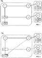
- Figure 1 is a schematic representation of a QKD system according to an embodiment of the invention in a first operating mode.
- the system 10a according to a first embodiment of the invention comprises a photon source 11, two optical links 12 and 13, an optical switch 14, a measurement device 15 and a memory 151.
- the system 10a communicates with two user devices 21 and 22 through the optical links 12 and 13 it comprises.
- the Quantum Key Distribution system 10a represented at Figure 1 is in a first operating mode called an "untrusted” mode because of the absence of a trusted node between the user devices.
- the Quantum Key Distribution System 10a in a second operating mode is represented at Figure 2 called a "trusted” mode because of the presence of a trusted node (system 10a or 10b) between the user devices.
- the "untrusted" mode is more secure than the "trusted” mode as the presence of the trusted node between the two user devices increases risks of keys being compromised, thus lowering security.
- the photon source 11 of the systems 10a and 10b does not need to be trusted for performing the methods of the invention.
- both user devices 21 and 22 are outside the system 10a, that is they are not located at the same place as the system 10a.
- the optical links 12 and 13 comprise telescopes on both ends of the optical links, for example, for each link: one telescope 12 in the system 10a and one telescope 211 in the user device 21.
- the optical links 12 and 13 can be optical fibre links, for example when the system 10a and both user devices 21 and 22 are on the ground.
- the optical links 21 and 22 are any component or device that makes it possible for the system 10a to send entangled photons to a user device 21 and/or 22.
- Two photons are entangled when the quantum state of a photon of a pair of entangled photons cannot be described independently of the quantum state of the other one.
- the photon source 11 is able to generate at least one pair of entangled photons.
- the photon source 11 will not be described as this is not the object of the invention, but the photon source 11 can be any component or device that can generate and emit at least entangled photons, for example using solutions where continuous laser light is injected in a non-linear crystal in which entangled photons pairs are created, followed by a means to separate the two photons of the pair.
- the photon source 11 therefore comprises at least two outputs to emit a photon on each output, the first photon of a pair of entangled photons being emitted on one of the two outputs, the second photon of the pair of entangled photons being emitted on the other of the two outputs.
- the links represented in solid continuous line are optical links that are active, i.e. represent the path followed by photons in a certain configuration.
- the links represented in dashed lines are inactive optical links, i.e. represent paths that photons cannot follow in that configuration.
- the links represented in dotted lines are common communication links, such as radio communication links, used to perform the "classical" steps in the QKD protocol.
- Optical links can be formed by optical trains, i.e. arrangements of optical components to guide photons, and can also comprise telescopes and free space channels (e.g. vacuum or air).
- the system 10a further comprises an optical switch 14, the optical switch comprising at least one input and at least two outputs, the optical switch receiving photons at its input and being able to route the photons to one of its outputs.
- the switch 14 changes the output it routes the received photons to, it is said to be “switching".
- the action of "switching" the optical switch 14 is the action of sending an instruction to the optical switch 14 to change the output it routes the received photons to, and the optical switch 14 effectively changing its routing output. This is represented at Figures 1 and 2 with a solid line for the routing output in use and a dashed line for the disabled output.
- the optical switches can be implemented using tuneable beam splitters, with switching the tuneable beam splitter comprising changing a predetermined split ratio of 100/0 to a predetermined split ratio of 0/100, where 100/0 means that 100% of received photons are routed towards the first output and 0% are routed towards the second output of the tuneable beam splitter.
- the first optical link 12 for example a telescope, is optically connected to the photon source 11 so as to receive photons from the photon source 11.
- the optical switch 14 is optically connected to the second output of the photon source 11 so as to receive photons from the photon source 11. Therefore, a first photon of a pair of entangled photons can be sent directly to user device 21 via the optical link 12, and a second photon of the pair of entangled photons can be sent to the other user device 22 via the optical switch 14 and via optical link 13 so as to carry out a BBM92 protocol with two on-ground receivers, or at least with two receivers exterior to the system 10a.
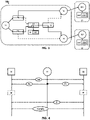
- This method implemented in the first operating mode of system 10a is represented at Figure 4 .
- Figure 4 is a schematic representation of a method carried out by the system according to an embodiment of the invention.
- This known method comprises a first step "init” that comprises the sharing of a secret for future authentication between user devices 21 and 22. This can be done during factory initialization or later using a known process. This secret is used for the first communication. For any subsequent communication, Alice and Bob use a small part of the future generated key (using QKD) for authentication.
- the photon source 11 sends a first photon P1 of a pair of entangled photons to user device 21 and a second photon P2 of the same pair of entangled photons to user device 22.
- each user device 21 and 22 comprises its own measurement device 212 and 222, the measurement devices 212 and 222 being trusted and comprising each their own memory 2121 and 2221 to store a key and/or a measure in a trusted manner.
- the invention also covers a system where the memory is not part of the measurement device, i.e. the memory and the measurement device are two distinct components or devices.
- the invention also covers a system where the measurement device comprises a memory, preferably a short-term memory, and where the system further comprises a memory device, which is preferably a long-term memory. This is not represented for clarity of the drawings.
- each user device 21 and 22 receiving a photon P1 or P2 measures a property of the received photon during a step "M" using their measurement device 212 or 222.
- Said property can be polarization of the photon, but it can be any other property in which the photons are entangled, as long as both user devices 21 and 22 measure the same property of the received photons of the same pair of entangled photons.
- each user device 21 and 22 After each measurement of a property of the entangled photons during the step "M" in a randomly selected basis, each user device 21 and 22 converts its measurement results to bits or any format.
- each user device 21 and 22 then reduces its results down to the results measured in the same basis as the other user device, then uses a part of its measurements to estimate the quantum bit error rate and generates a secure key K from the rest of its measurement results, thus creating a common key "K”.
- Each user device 21 and 22 stores its key in its memory 2121 and 2221. Using the key K, user devices 21 and 22 can then encrypt their communications to communicate in a step "Com", or generate derived keys to be used for that purpose.
- the optical switch 14 In a second operating "trusted” mode, the optical switch 14 is switched to its second output, thus routing photons received at its input towards the measurement device 15. The photons received by the optical switch 14 are consequently not routed towards the second optical link 13.
- a user device receives one photon of the pair of entangled photons generated by the photon source 11 and the measurement device 15 receives the other photon of the pair of entangled photons generated by the photon source 11.
- this permits to have a common trusted key (e.g. Ka in Figure 5 ) between the system 10a and the user device 21 or 22.
- the same process is repeated with the other user device 21 or 22 thanks to the optical switch 14, to obtain another trusted key (e.g. Kb in Figure 5 ) between the system 10a and the other user device 21 or 22.
- the system 10a can therefore securely communicate to one user device the key established with the other device. This permits to have a key to communicate between user device 21 and user device 22, with the system 10a acting as a trusted central entity.
- the method of Figure 5 will later be referred to as a "trusted” method, as a key is distributed between user devices 21 and 22 with a trusted component (system 10a and in particular measurement device 15) between them storing the key or part of the key.
- a trusted system 10a and in particular measurement device 15
- Figure 5 is a schematic representation of a method in a "trusted" mode carried out by the system according to an embodiment of the invention.
- This other method comprises two first authentication steps "Auth” that comprises the sharing of a secret for future authentication between user device 21 and system 10a/10b and between user device 22 and system 10a/10b. This can be done during factory initialization or later using a trusted known process. Overall, the different steps of this other method resemble the BB84 protocol, with the difference that the same entangled photon source is used as for BBM92.
- the photon source 11 then sends a first photon P3 of a pair of entangled photons to user device 21 and a second photon P4 of the same pair of entangled photons to the on-board measurement device 15.
- the user device 21 receiving the photon P3 and the on-board measurement device 15 receiving the photon P4 measure a property of the received photon during a step "M".
- Said property can be polarization of the photon, but it can be any other property, as long as both user device 21 and measurement device 15 measure the same property of the received photons of the same pair of photons entangled in this property.
- the measurement device 15 stores the measure in the memory 151 in a step "M1" represented at Figure 5 . It has to be noted that the measurement device 15 as well as all the other measurement devices in the specification have to be trusted parts of the system.
- the key Ka is then generated from the measurement carried out previously and can also be stored in the memory 151.
- the optical link 12 is implemented as a telescope
- the telescope can be directed first towards the first user device 21 in the first part of the method and then towards the second user device 22 in the second part of the method, therefore using the same telescope and the same optical route within the system 10a to route the photons to each user device.
- the optical link 12 is implemented as an optical fibre, an optical switch (not represented) is needed to switch between the first and second user device 21 and 22. Being able to switch between user device 21 and 22 permits to implement the first part of the method represented at Figure 5 and then the second part of the method represented at Figure 5 , thus enabling to create a common communication key between user devices 21 and 22.
- the second part of the method of Figure 5 is carried out, that is the photon source 11 sends a first photon P5 of a pair of entangled photons to user device 22 and a second photon P6 of the same pair of entangled photons to the on-board measurement device 15.
- the measurement device 15 transfers the measurement of the property and/or the key Kb to the memory 151 in a step "M2" represented at Figure 5 . Therefore, both the user device 22 and the system 10a can communicate in an encrypted way using their shared key Kb.
- the user devices 21 and 22 can communicate after any device or component comprised in the system 10a sends the key Ka encrypted with the key Kb to user device 22 in a step "XOR", so that user device 22 then knows the key Ka and can communicate with the user device 21 using this key Ka. Note that this also works when any device or component comprised in the system 10a sends the key Kb encrypted with the key Ka to user device 21 so that user device 21 then knows the key Kb and can communicate with the user device 22 using this key Kb.
- the method of Figure 4 is very secure, as it does not need a trusted "middleman", i.e. a trusted component holding two keys Ka and Kb, but has the following drawbacks:
- the method of Figure 4 has drawbacks that are solved by the method of Figure 5 , mainly regarding a link budget issue and the method of Figure 5 has drawbacks that are solved by the method of Figure 4 , mainly regarding the presence of a trusted component between the user devices 21 and 22.
- the invention permits to switch between different services to better adapt to the will of the users.
- FIG. 3 Another embodiment of the system according to the invention is represented at Figure 3 .
- Figure 3 shows a schematic representation of a QKD system according to another embodiment of the invention.
- the system 10b according to another embodiment of the invention represented at Figure 3 permits to operate both methods of Figure 4 and 5 at once by simply switching different optical paths of the system 10b. This is represented at Figure 6 .
- Figure 6 By having a single system able to simultaneously carry out both methods of Figure 4 and Figure 5 , it is possible to overcome the drawbacks of both methods in one single method.
- the system 10b comprises the components of the system 10a and additional components.
- the system 10b comprises an optical switch 16 between the first output of the photon source 11 and the optical link 12.
- the added optical switch 16 receives photons from the photon source 11 and can route the received photons to either its first output, connected to the first optical link 12, or to its second output.
- the system 10b further comprises a beam splitter 17, located between the optical switch 14 and the measurement device 15.
- the beam splitter 17 has two inputs and two outputs.
- the beam splitter 17 receives photons from its first or second outputs and splits the received photon stream between its two outputs. That is, the beam splitter for example has a 50/50 predetermined split ratio and splits evenly the received photons stream between its first and second outputs.
- the beam splitter 17 is a tuneable beam splitter that has a tuneable predetermined split ratio.
- the first output of the beam splitter 17 is connected to a user device, while the second output of the beam splitter 17 is connected to the measurement device, so that some of the photons received by the beam splitter 17 can be routed towards a user device 21 or 22 and other received photons can have a property measured.
- the beam splitter 17 can only have one input and receive photons either from optical switches 14 or 16. It should be noted that the beam splitter works randomly, so there is a statistical effect where part of the photons are routed to one output, and the other part of the photons goes to the other output, randomly. After measurement, a "reconciliation" process is carried out based on the exact time of arrival of photons to reconstruct the pairs of photons, i.e. to understand which photons arrived where.
- the system 10b further comprises an optical switch 18 having its input connected to the first output of the beam splitter 17, and having two outputs, the first output of the optical switch 18 being connected to the first user device 21 via the first optical link 12, and the second output of the optical switch 18 being connected to the second user device 22 via the second optical link 13.
- This permits to route some photons received by the beam splitter 17 either to user device 21 or to user device 22 while being able to measure a property of some other photons also received by the beam splitter 17.
- the method carried out by the system 10b according to the invention is in two parts separated by at least one switching of at least one optical switch. As represented at Figure 3 , the whole system can be switched at once by switching each optical switch 14, 16 and 18.
- a photon stream comprising photons from at least two pairs of entangled photons is sent to the user device 21 and to the beam splitter 17, which separates the received stream in two, to route a part of the photon stream to the measurement device 15 and another part of the photon stream to the user device 22.
- Figure 6 is a schematic representation of a method carried out by the system according to another embodiment of the invention, i.e. by the "hybrid" system.
- the method of Figure 6 comprises two first authentication steps "Auth” comprising the sharing of a secret for future authentication between user device 21 and system 10b and between user device 22 and system 10b.
- the method carried out by the hybrid architecture 10b of Figure 3 then comprises a step of generating two pairs of entangled photons.
- the first photon of each pair will be referred to as photon stream P7.
- the second photon of each pair will be referred to as photon stream P8, and in particular the second photon of the first pair of entangled photons will be referred to as P8.1 and the second photon of the second pair of entangled photons will be referred to as P8.2.
- the first stream of photons P7 is routed from the photon source 11 to the user device 21 via the optical switch 16 and the optical link 12.
- the second stream of photons P8 is routed from the photon source 11 to the beam splitter 17 via the optical switch 14. There, the stream is split in a part P8.1 and a part P8.2. Part P8.1 is routed to the measurement device 15 and part P8.2 is routed to the user device 22 through the first output of the beam splitter 17, the optical switch 18 and the optical link 13.
- the user device 21 and the user device 22 each measure a property of the received photon(s) P7 and P8.2, enabling to create a common "short" key K1 to communicate between themselves, as in the method of Figure 4 presented previously.
- the user device 21 and the measurement device 15 each measure a property of the received photon(s) P7 and P8.1, enabling to create a common "short" key Ka to communicate between themselves, as in the method of Figure 5 presented previously.
- the measure of the property is stored in a step M3 in the memory 151 of measurement device 15. Key Ka is then generated for future use, based on the measurement of the property.
- the key Ka can be stored in the memory 151 as well.
- the method then comprises a step of generating two pairs of entangled photons.
- the first photon of each pair will be referred to as photon stream P9.
- the second photon of each pair will be referred to as photon stream P10, and in particular the second photon of the first pair of entangled photons will be referred to as P10.1 and the second photon of the second pair of entangled photons will be referred to as P10.2.
- the first stream of photons P9 is routed from the photon source 11 to the user device 22 via the optical switch 14 and the optical link 13.
- the second stream of photons P10 is routed from the photon source 11 to the beam splitter 17 via the optical switch 16. There, the stream is split in a part P10.1 and a part P10.2. Part P10.1 is routed to the measurement device 15 and part P10.2 is routed to the user device 21 through the first output of the beam splitter 17, the optical switch 18 and the optical link 12.
- the user device 21 and the user device 22 each measure a property of the received photon(s) P9 and P10.2, enabling to create a common "short" key K2 to communicate between themselves, as in the method of Figure 4 presented previously.
- the user device 22 and the measurement device 15 each measure a property of the received photon(s) P9 and P10.1, enabling to create a common "short" key Kb to communicate between themselves, as in the method of Figure 5 presented previously.
- the measurement of the property and/or the Key Kb generated based on the measurement are transferred in a step M4 to the memory 151 of measurement device 15.
- the user devices 21 and 22 can communicate as any device or component comprised in the system 10a sends the key Ka encrypted with the key Kb to user device 22 in a step "XOR", so that user device 22 then knows the key Ka and can communicate with the user device 21 using this key Ka. Note that this also works when any device or component comprised in the system 10b sends the key Kb encrypted with the key Ka to user device 21 so that user device 21 then knows the key Kb and can communicate with the user device 22 using this key Kb.
- the proposed architecture is innovative in that it permits in in a hybrid manner:
- K1, K2 and Kb can be combined using a hash function or other algorithm to create a uniform (equal probability for all bit outcomes) and secure key K3 which can be used for encryption.
- L(.) the length of a key k
- L(K1)+L(K2) ⁇ L(K3) L(K1)+L(K2)+L(Kb)
- further modelling of the probability that all or parts of Kb are compromised in trusted mode is required in order to properly define the final length of the resulting key.
- the conditional min-entropy can be used.
- K2 generated in trusted mode
- conditional min-entropy of K2 can be determined.
- a suitable hash function can be applied on input K1 and K2 to obtain a uniformly random key K3. This allows maximum flexibility for the user of the system to choose appropriate parameters to determine the length of the absolutely secure keys (K1, K2), the length of the "trusted" key (Ka), and the length of the final key (K3).
- the parameters can change for each user and also change over time, i.e. they are not fixed in the system.
- the splitting ratio also depends on the expected 'trustiness' of the key generated in trusted mode, determined by the probability of selected information variables related to the generated key in trusted mode. If the probability of compromise of (parts of) the key (Kb) is high, then more photons are needed for the untrusted mode of Figure 4 . Alternatively, the number of photons send in the trusted mode of Figure 5 can be increased if the model predicts low chance of compromise.
- the system allows to change these parameters for each user, and over time, therefore is especially suited for applications (such as deployment on satellites) where the same hardware will be used for a long period of time and cannot be changed easily.
Landscapes
- Engineering & Computer Science (AREA)
- Physics & Mathematics (AREA)
- Electromagnetism (AREA)
- Computer Networks & Wireless Communication (AREA)
- Signal Processing (AREA)
- Optics & Photonics (AREA)
- Theoretical Computer Science (AREA)
- Computer Security & Cryptography (AREA)
- Optical Communication System (AREA)
- Optical Modulation, Optical Deflection, Nonlinear Optics, Optical Demodulation, Optical Logic Elements (AREA)
- Photometry And Measurement Of Optical Pulse Characteristics (AREA)
Priority Applications (4)
| Application Number | Priority Date | Filing Date | Title |
|---|---|---|---|
| EP21305157.6A EP4040715A1 (fr) | 2021-02-05 | 2021-02-05 | Systèmes de distribution de clé quantique et procédés associés |
| PCT/EP2022/052600 WO2022167534A1 (fr) | 2021-02-05 | 2022-02-03 | Systèmes de distribution de clés quantiques et procédés associés |
| US18/264,168 US12483338B2 (en) | 2021-02-05 | 2022-02-03 | Quantum key distribution systems and associated methods |
| CA3207218A CA3207218A1 (fr) | 2021-02-05 | 2022-02-03 | Systemes de distribution de cles quantiques et procedes associes |
Applications Claiming Priority (1)
| Application Number | Priority Date | Filing Date | Title |
|---|---|---|---|
| EP21305157.6A EP4040715A1 (fr) | 2021-02-05 | 2021-02-05 | Systèmes de distribution de clé quantique et procédés associés |
Publications (1)
| Publication Number | Publication Date |
|---|---|
| EP4040715A1 true EP4040715A1 (fr) | 2022-08-10 |
Family
ID=75302436
Family Applications (1)
| Application Number | Title | Priority Date | Filing Date |
|---|---|---|---|
| EP21305157.6A Pending EP4040715A1 (fr) | 2021-02-05 | 2021-02-05 | Systèmes de distribution de clé quantique et procédés associés |
Country Status (4)
| Country | Link |
|---|---|
| US (1) | US12483338B2 (fr) |
| EP (1) | EP4040715A1 (fr) |
| CA (1) | CA3207218A1 (fr) |
| WO (1) | WO2022167534A1 (fr) |
Families Citing this family (1)
| Publication number | Priority date | Publication date | Assignee | Title |
|---|---|---|---|---|
| WO2024059063A1 (fr) * | 2022-09-12 | 2024-03-21 | Quantum Technologies Laboratories, Inc. | Distribution de clé quantique mobile dans l'espace |
Citations (3)
| Publication number | Priority date | Publication date | Assignee | Title |
|---|---|---|---|---|
| US7460670B1 (en) * | 2002-12-20 | 2008-12-02 | Bbn Technologies Corp. | Systems and methods for managing quantum cryptographic networks |
| WO2012074369A1 (fr) * | 2010-12-02 | 2012-06-07 | Mimos Berhad | Système et procédé de distribution de clé quantique échangeable |
| US20200153619A1 (en) * | 2015-12-21 | 2020-05-14 | Id Quantique Sa | Apparatus and method for adding an entropy source to quantum key distribution systems |
Family Cites Families (5)
| Publication number | Priority date | Publication date | Assignee | Title |
|---|---|---|---|---|
| US8311221B2 (en) * | 2008-01-15 | 2012-11-13 | At&T Intellectual Property Ii, L.P. | Architecture for reconfigurable quantum key distribution networks based on entangled photons directed by a wavelength selective switch |
| EP2555466B1 (fr) * | 2011-08-05 | 2014-07-02 | SELEX ES S.p.A. | Système de distribution de clés cryptographiques |
| US9313180B1 (en) * | 2015-03-31 | 2016-04-12 | Corning Incorporated | Systems and methods for quantum key generation |
| GB2555100B (en) * | 2016-10-14 | 2020-07-08 | Toshiba Res Europe Limited | A photon source and a method of fabricating a photon source |
| US10225080B2 (en) * | 2016-11-29 | 2019-03-05 | The United States Of America As Represented By The Secretary Of The Army | Method and systems for routing entangled photons to quantum network users via a reconfigurable switch networks of optical crossbar switches |
-
2021
- 2021-02-05 EP EP21305157.6A patent/EP4040715A1/fr active Pending
-
2022
- 2022-02-03 US US18/264,168 patent/US12483338B2/en active Active
- 2022-02-03 WO PCT/EP2022/052600 patent/WO2022167534A1/fr not_active Ceased
- 2022-02-03 CA CA3207218A patent/CA3207218A1/fr active Pending
Patent Citations (3)
| Publication number | Priority date | Publication date | Assignee | Title |
|---|---|---|---|---|
| US7460670B1 (en) * | 2002-12-20 | 2008-12-02 | Bbn Technologies Corp. | Systems and methods for managing quantum cryptographic networks |
| WO2012074369A1 (fr) * | 2010-12-02 | 2012-06-07 | Mimos Berhad | Système et procédé de distribution de clé quantique échangeable |
| US20200153619A1 (en) * | 2015-12-21 | 2020-05-14 | Id Quantique Sa | Apparatus and method for adding an entropy source to quantum key distribution systems |
Non-Patent Citations (3)
| Title |
|---|
| C. BONATOA. TOMAELLOV. DA DEPPOG. NALETTOP. VILLORESI: "Feasibility of satellite quantum key distribution", NEW JOURNAL OF PHYSICS, vol. 11, April 2009 (2009-04-01) |
| JUAN YIN ET AL.: "Satellite-to-Ground Entanglement-Based Quantum Key Distribution", PHYSICAL REVIEW LETTERS, vol. 119, pages 2017 |
| TOM VERGOOSSEN ET AL: "Satellite quantum communications when man-in-the-middle attacks are excluded", ARXIV.ORG, CORNELL UNIVERSITY LIBRARY, 201 OLIN LIBRARY CORNELL UNIVERSITY ITHACA, NY 14853, 6 March 2019 (2019-03-06), XP081162328 * |
Also Published As
| Publication number | Publication date |
|---|---|
| US20240097794A1 (en) | 2024-03-21 |
| US12483338B2 (en) | 2025-11-25 |
| WO2022167534A1 (fr) | 2022-08-11 |
| CA3207218A1 (fr) | 2022-08-11 |
Similar Documents
| Publication | Publication Date | Title |
|---|---|---|
| US20240178994A1 (en) | Secure symmetric key distribution | |
| Liao et al. | Satellite-relayed intercontinental quantum network | |
| US20200396067A1 (en) | Quantum protection of telemetry tracking and command links | |
| EP1755269B1 (fr) | Système de communication secrète et procédé de génération d'une information secrète partagée | |
| US10439808B2 (en) | Communication with everlasting security from short-term-secure encrypted quantum communication | |
| EP2281361B1 (fr) | Distribution de clé quantique impliquant un dispositif de clé amovible | |
| Orsucci et al. | Assessment of Practical Satellite Quantum Key Distribution Architectures for Current and Near‐Future Missions | |
| JP2013539324A (ja) | 通信信頼機関によって管理される量子鍵配送を伴う安全なマルチパーティ通信 | |
| Grieve et al. | SpooQySats: CubeSats to demonstrate quantum key distribution technologies | |
| US12603766B2 (en) | QKD switching system and protocols | |
| Rani et al. | Combined quantum and post-quantum security for Earth-satellite channels | |
| Vyas et al. | Relaxing trust assumptions on quantum key distribution networks | |
| De Santis et al. | Parallel trusted node approach for satellite quantum key distribution | |
| Chen et al. | Multiple-pulse phase-matching quantum key distribution | |
| US12483338B2 (en) | Quantum key distribution systems and associated methods | |
| US20250211430A1 (en) | Centralized satellite quantum cryptographic key pairing method | |
| JP2025038894A (ja) | 衛星を含むネットワーク内で秘密鍵を共有するための方法及びデバイス | |
| WO2024059063A1 (fr) | Distribution de clé quantique mobile dans l'espace | |
| Le et al. | Enhancement of AGT telecommunication security using quantum cryptography. | |
| US20250038970A1 (en) | Quantum key distribution (qkd) method, qkd end-node and qkd network | |
| US20260128867A1 (en) | Secure Communications Among Multiple Entities Using Quantum Entanglement | |
| Dodson et al. | Updating quantum cryptography report ver. 1 | |
| Khudoyqulova et al. | Secure Quantum Key Distribution over Long-Haul Optical Fibers Using Twin-Field QKD Protocol | |
| Mitlyng et al. | Global Quantum Key Distribution using CubeSat-Based Photon Sources | |
| Ali | Hybrid quantum key distribution: A novel approach for secure end-to-end communication in network infrastructure |
Legal Events
| Date | Code | Title | Description |
|---|---|---|---|
| PUAI | Public reference made under article 153(3) epc to a published international application that has entered the european phase |
Free format text: ORIGINAL CODE: 0009012 |
|
| STAA | Information on the status of an ep patent application or granted ep patent |
Free format text: STATUS: THE APPLICATION HAS BEEN PUBLISHED |
|
| AK | Designated contracting states |
Kind code of ref document: A1 Designated state(s): AL AT BE BG CH CY CZ DE DK EE ES FI FR GB GR HR HU IE IS IT LI LT LU LV MC MK MT NL NO PL PT RO RS SE SI SK SM TR |
|
| STAA | Information on the status of an ep patent application or granted ep patent |
Free format text: STATUS: REQUEST FOR EXAMINATION WAS MADE |
|
| 17P | Request for examination filed |
Effective date: 20230207 |
|
| RBV | Designated contracting states (corrected) |
Designated state(s): AL AT BE BG CH CY CZ DE DK EE ES FI FR GB GR HR HU IE IS IT LI LT LU LV MC MK MT NL NO PL PT RO RS SE SI SK SM TR |
|
| P01 | Opt-out of the competence of the unified patent court (upc) registered |
Effective date: 20230602 |
|
| STAA | Information on the status of an ep patent application or granted ep patent |
Free format text: STATUS: EXAMINATION IS IN PROGRESS |
|
| 17Q | First examination report despatched |
Effective date: 20250311 |