EP4040671A1 - Motor drive device - Google Patents
Motor drive device Download PDFInfo
- Publication number
- EP4040671A1 EP4040671A1 EP20873195.0A EP20873195A EP4040671A1 EP 4040671 A1 EP4040671 A1 EP 4040671A1 EP 20873195 A EP20873195 A EP 20873195A EP 4040671 A1 EP4040671 A1 EP 4040671A1
- Authority
- EP
- European Patent Office
- Prior art keywords
- mosfets
- mosfet
- neutral point
- phase
- motor
- Prior art date
- Legal status (The legal status is an assumption and is not a legal conclusion. Google has not performed a legal analysis and makes no representation as to the accuracy of the status listed.)
- Pending
Links
Images



Classifications
-
- H—ELECTRICITY
- H02—GENERATION; CONVERSION OR DISTRIBUTION OF ELECTRIC POWER
- H02P—CONTROL OR REGULATION OF ELECTRIC MOTORS, ELECTRIC GENERATORS OR DYNAMO-ELECTRIC CONVERTERS; CONTROLLING TRANSFORMERS, REACTORS OR CHOKE COILS
- H02P27/00—Arrangements or methods for the control of AC motors characterised by the kind of supply voltage
- H02P27/04—Arrangements or methods for the control of AC motors characterised by the kind of supply voltage using variable-frequency supply voltage, e.g. inverter or converter supply voltage
- H02P27/06—Arrangements or methods for the control of AC motors characterised by the kind of supply voltage using variable-frequency supply voltage, e.g. inverter or converter supply voltage using DC to AC converters or inverters
-
- H—ELECTRICITY
- H02—GENERATION; CONVERSION OR DISTRIBUTION OF ELECTRIC POWER
- H02M—APPARATUS FOR CONVERSION BETWEEN AC AND AC, BETWEEN AC AND DC, OR BETWEEN DC AND DC, AND FOR USE WITH MAINS OR SIMILAR POWER SUPPLY SYSTEMS; CONVERSION OF DC OR AC INPUT POWER INTO SURGE OUTPUT POWER; CONTROL OR REGULATION THEREOF
- H02M1/00—Details of apparatus for conversion
- H02M1/32—Means for protecting converters other than automatic disconnection
- H02M1/325—Means for protecting converters other than automatic disconnection with means for allowing continuous operation despite a fault, i.e. fault tolerant converters
-
- H—ELECTRICITY
- H02—GENERATION; CONVERSION OR DISTRIBUTION OF ELECTRIC POWER
- H02M—APPARATUS FOR CONVERSION BETWEEN AC AND AC, BETWEEN AC AND DC, OR BETWEEN DC AND DC, AND FOR USE WITH MAINS OR SIMILAR POWER SUPPLY SYSTEMS; CONVERSION OF DC OR AC INPUT POWER INTO SURGE OUTPUT POWER; CONTROL OR REGULATION THEREOF
- H02M7/00—Conversion of AC power input into DC power output; Conversion of DC power input into AC power output
- H02M7/42—Conversion of DC power input into AC power output without possibility of reversal
- H02M7/44—Conversion of DC power input into AC power output without possibility of reversal by static converters
- H02M7/48—Conversion of DC power input into AC power output without possibility of reversal by static converters using discharge tubes with control electrode or semiconductor devices with control electrode
- H02M7/53—Conversion of DC power input into AC power output without possibility of reversal by static converters using discharge tubes with control electrode or semiconductor devices with control electrode using devices of a triode or transistor type requiring continuous application of a control signal
- H02M7/537—Conversion of DC power input into AC power output without possibility of reversal by static converters using discharge tubes with control electrode or semiconductor devices with control electrode using devices of a triode or transistor type requiring continuous application of a control signal using semiconductor devices only, e.g. single switched pulse inverters
- H02M7/5387—Conversion of DC power input into AC power output without possibility of reversal by static converters using discharge tubes with control electrode or semiconductor devices with control electrode using devices of a triode or transistor type requiring continuous application of a control signal using semiconductor devices only, e.g. single switched pulse inverters in a bridge configuration
-
- H—ELECTRICITY
- H02—GENERATION; CONVERSION OR DISTRIBUTION OF ELECTRIC POWER
- H02P—CONTROL OR REGULATION OF ELECTRIC MOTORS, ELECTRIC GENERATORS OR DYNAMO-ELECTRIC CONVERTERS; CONTROLLING TRANSFORMERS, REACTORS OR CHOKE COILS
- H02P25/00—Arrangements or methods for the control of AC motors characterised by the kind of AC motor or by structural details
- H02P25/16—Arrangements or methods for the control of AC motors characterised by the kind of AC motor or by structural details characterised by the circuit arrangement or by the kind of wiring
- H02P25/18—Arrangements or methods for the control of AC motors characterised by the kind of AC motor or by structural details characterised by the circuit arrangement or by the kind of wiring with arrangements for switching the windings, e.g. with mechanical switches or relays
-
- H—ELECTRICITY
- H02—GENERATION; CONVERSION OR DISTRIBUTION OF ELECTRIC POWER
- H02P—CONTROL OR REGULATION OF ELECTRIC MOTORS, ELECTRIC GENERATORS OR DYNAMO-ELECTRIC CONVERTERS; CONTROLLING TRANSFORMERS, REACTORS OR CHOKE COILS
- H02P25/00—Arrangements or methods for the control of AC motors characterised by the kind of AC motor or by structural details
- H02P25/16—Arrangements or methods for the control of AC motors characterised by the kind of AC motor or by structural details characterised by the circuit arrangement or by the kind of wiring
- H02P25/22—Multiple windings; Windings for more than three phases
-
- H—ELECTRICITY
- H02—GENERATION; CONVERSION OR DISTRIBUTION OF ELECTRIC POWER
- H02P—CONTROL OR REGULATION OF ELECTRIC MOTORS, ELECTRIC GENERATORS OR DYNAMO-ELECTRIC CONVERTERS; CONTROLLING TRANSFORMERS, REACTORS OR CHOKE COILS
- H02P29/00—Arrangements for regulating or controlling electric motors, appropriate for both AC and DC motors
- H02P29/02—Providing protection against overload without automatic interruption of supply
- H02P29/024—Detecting a fault condition, e.g. short circuit, locked rotor, open circuit or loss of load
- H02P29/028—Detecting a fault condition, e.g. short circuit, locked rotor, open circuit or loss of load the motor continuing operation despite the fault condition, e.g. eliminating, compensating for or remedying the fault
-
- H—ELECTRICITY
- H02—GENERATION; CONVERSION OR DISTRIBUTION OF ELECTRIC POWER
- H02P—CONTROL OR REGULATION OF ELECTRIC MOTORS, ELECTRIC GENERATORS OR DYNAMO-ELECTRIC CONVERTERS; CONTROLLING TRANSFORMERS, REACTORS OR CHOKE COILS
- H02P29/00—Arrangements for regulating or controlling electric motors, appropriate for both AC and DC motors
- H02P29/02—Providing protection against overload without automatic interruption of supply
- H02P29/032—Preventing damage to the motor, e.g. setting individual current limits for different drive conditions
Definitions
- the present invention relates to a motor drive device that drives a motor.
- a motor and an inverter that are responsible for a forward driving force of a vehicle of an electric vehicle is also required to maintain a driving force enough to move a vehicle on which a human rides at the time of failure to at least a safe shoulder, and a fail-operational configuration is required.
- a motor drive device in which an inverter that drives a motor of a plurality of phases having a plurality of coils can continuously drive the motor even when a failure occurs in any phase.
- PTL 1 discloses that "a motor in which coils of a plurality of phases of five or more phases are connected by star connection, an inverter that is connected to one end of each phase coil, converts DC power into AC power, and supplies the AC power to each phase of the motor, a power relay that is disposed on the other end side of each phase coil, and is configured to be able to cut off power supplied to coils of one or more phases among the coils of the plurality of phases of the motor by using a plurality of contacts inserted between the coils star-connected, and a control unit that controls driving of the motor by generating a control signal of the inverter are provided, and when one or more phases of the motor fail, the control unit opens the contact of the power relay corresponding to the failed phase, and drives three or more phases at substantially the same interval among the plurality of remaining phases". This configuration allows the motor to be continuously driven even when any phase of the motor fails.
- a power relay is used to separate a failed phase from other normal phases.
- each relay is configured by a semiconductor relay including a metal-oxide-semiconductor field-effect transistor (MOSFET)
- MOSFETs in two series are required in order to prevent conduction due to a parasitic diode. Therefore, in the motor drive device described in PTL 1, the number of MOSFETs connected in series via the current path from the power supply to the ground increases, and the on-resistance increases accordingly, and the power loss may increase.
- MOSFET metal-oxide-semiconductor field-effect transistor
- An object of the present invention is to provide a motor drive device capable of not only continuing an operation by remaining phases when a certain phase among a plurality of phases fails, but also performing a highly efficient operation with a small power loss even in a normal state.
- the present invention is a motor drive device that drives a plurality of coils of a motor by an inverter, in which a first neutral point and a second neutral point different from the inverter are formed in advance by being connected in parallel to the plurality of coils, the motor drive device including: first MOSFETs between the first neutral point and coils connected, the first MOSFETs each having a cathode, of a body diode, on a coil side; and second MOSFETs between the second neutral point and coils connected, the second MOSFETs each having an anode, of a body diode, on a coil side.
- a motor drive device capable of not only continuing an operation by remaining phases when a certain phase among a plurality of phases fails but also performing a highly efficient operation with a small power loss even in a normal state.
- FIG. 1 is a circuit diagram illustrating an example of a motor drive device and a five-phase motor 1 according to the present embodiment.
- the motor drive device includes a five-phase inverter 2 to which a DC voltage is supplied from a power supply, and a neutral point switching unit 3 that forms a neutral point in advance for each phase of the five-phase motor 1.
- the five-phase inverter 2 includes a fourth MOSFET group of M41 to M45 and a fifth MOSFET group of M51 to M55.
- the fourth MOSFET group of M41 to M45 is a semiconductor switching element group that is on the high potential side of the five-phase inverter 2 and constitute the upper arms
- the fifth MOSFET group of M51 to M55 includes semiconductor switching elements that are on the low potential side of the five-phase inverter 2 and constitute the lower arms.
- the on/off of the switching element group is controlled by a control signal from an inverter control unit (not illustrated).
- a third MOSFET group of M31 to M35 is provided between the five-phase inverter 2 and the ground, and the third MOSFET group of M31 to M35 is connected in series with the respective phase outputs of the fifth MOSFET group of M51 to M55.
- the body diodes of the third MOSFET group of M31 to M35 are connected in a direction in which a current flows to the ground. That is, in each of the third MOSFET group of M31 to M35, the body diode is oriented such that the cathode is located on the ground side.
- the body diode is assumed to be a parasitic diode inevitably formed due to the structure of the MOSFET, but may be a diode intentionally provided.
- the third MOSFET group of M31 to M35 plays a role of preventing a regenerative current from flowing through the five-phase motor 1 when a ground fault occurs in the wiring of the five-phase motor 1 on the neutral point switching unit 3 side.
- the five-phase motor 1 is a brushless motor including a rotor (not illustrated) and five-phase coils (W1 to W5) wound around a stator.
- One end of the coil of each phase is connected to the upper arm and the lower arm of each phase of the five-phase inverter 2.
- the other ends of the coil of respective phases are connected to the first MOSFET group of M11 to M15 and the second MOSFET group of M21 to M25 provided in the neutral point switching unit 3 to be described later.
- the neutral point switching unit 3 forms two neutral points in advance for the coil of each phase of the five-phase motor 1 via the first MOSFET group of M11 to M15 and the second MOSFET group of M21 to M25 connected in parallel. Then, when a certain phase of the five-phase inverter 2 fails, the neutral point switching unit 3 appropriately turns on/off each MOSFET group as described later according to a control signal from a neutral point control unit (not illustrated), and interrupts and separates the failed phase from the five-phase motor 1.
- the first MOSFET group of M11 to M15 each has one end connected to the five-phase motor 1, and the other end star-connected to each other to form a neutral point 4 which is a first neutral point.
- the second MOSFET group of M21 to M25 each has one end connected to the five-phase motor 1, and the other end star-connected to each other to form a neutral point 5 which is a second neutral point. Note that neither the neutral point 4 nor the neutral point 5 is connected to the power supply or the ground.
- the first MOSFET group of M11 to M15 each has a body diode that is oriented such that the cathode is located toward the coil of the five-phase motor 1.
- the second MOSFET group of M21 to M25 each has a body diode that is oriented such that the anode is located toward the coil of the five-phase motor 1.
- a failure detection unit for detecting a failure of the five-phase inverter 2 and each MOSFET is provided.
- the failure detection unit it is conceivable to detect a failure of the MOSFET by monitoring a voltage between a drain and a source of the MOSFET and comparing the voltage with a predetermined threshold value.
- it is conceivable to detect the current flowing through each phase detect that the current is excessive or insufficient by comparing the current with a predetermined threshold value, and detect the failure of the wiring and the five-phase motor 1.
- the fault detection method other widely known fault detection methods can be used.
- FIG. 2 is a diagram illustrating an on/off state of each MOSFET in a normal state in which no failure occurs.
- a normal state all of the MOSFETs (the first MOSFET group of M11 to M15 and the second MOSFET group of M21 to M25) in the neutral point switching unit 3 and all of the MOSFETs (the third MOSFET group of M31 to M35) for regenerative current prevention are turned on, and the device is operated as a five-phase inverter and a motor that are star-connected at the neutral point 4 and the neutral point 5.
- the failure of the MOSFET of the inverter is roughly divided into a “short-circuit failure” and an “open failure".
- the "short-circuit failure” refers to a failure in which the switch is always in a conducting state due to a short circuit between the source and the drain of the MOSFET
- the "open failure” refers to a failure in which the switch is always in a cutoff state due to opening between the source and the drain of the MOSFET.
- the voltage of the coil W5, connected to the M45, on the neutral point (neutral point switching unit 3) side has a value obtained by superimposing the induced voltage of the motor on the battery voltage. Since this voltage is higher than the neutral point voltage that is 1/2 of the battery voltage, the coil W5 is cut off from the neutral point 4 by turning off the M45 corresponding to the phase of the M15 in which the short-circuit failure has occurred, and the neutral point 4 is protected from overvoltage. Note that M11 to M14 remain in an on state. On the other hand, even when the M25 is turned off, the current flows into the neutral point 5 by the body diode, but the current can be cut off by turning off all the M21 to M25.
- the M55 in the same phase as the M45 is also turned off.
- the operation can be continued as the four-phase motor by the remaining coils W1 to W4 even when each MOSFET of the neutral point switching unit 3 remains ON.
- the M55 in the same phase as the M45 is turned off.
- the M55 When the open failure occurs in the M55, the current does not flow in the coil W5, and the operation can be continued as the four-phase motor by the remaining coils W1 to W4 even when each MOSFET of the neutral point switching unit 3 remains ON. At this time, in the fourth MOSFET group constituting the upper arms, the M55 in the same phase as the M45 is turned off.
- the M35, of the upper arm, in the same phase as the M45 is turned off.
- the operation is continued as a four-phase motor by the remaining four phases excluding the phase of the M35 in which the open failure has occurred.
- the M15 and the M25 corresponding to the phase of the M35 may be turned on or off.
- the failure of the five-phase motor 1 is roughly divided into a short-circuit failure and a disconnection failure of each of the coils W1 to W5, and a ground fault in which the wiring is short-circuited to the ground.
- the short-to-power fault in which the wiring is short-circuited to the power source since all the housings of the motor and the inverter have the ground potential in the case of the vehicle, the probability of occurrence of the short-to-power fault is very low as compared with the case of the ground fault, so that it is possible to ignored the fault.
- the short-circuit failure of the coil is a short-circuit that occurs in the coil, for example, a flaw or a defect of the coil coating, and the inductance of the coil is significantly reduced or the generated magnetic field is weakened.
- the short-circuit failure of each of the coils W1 to W5 by turning off the MOSFETs of the upper arm and the lower arm of the inverter phase connected to the failed coil, the current to the failed coil is cut off, and the operation as the motor can be continued in the remaining four phases.
- the M45 and the M55 are turned off, so that an unintended current can be blocked from flowing through the coil W5.
- the disconnection failure of the coil occurs when an electric wire constituting the coil is broken due to fatigue caused by burning or mechanical vibration.
- a disconnection failure of the coil occurs, a current cannot flow through the coil, and a magnetic force cannot be generated.
- the remaining coils W1 to W4 can continue the operation of the motor. It is not necessary to operate the MOSFET of the neutral point switching unit 3 or the MOSFET for regenerative current prevention.
- the M45 and the M55 that are MOSFETs of the five-phase inverter 2 connected to the coil W5 are also turned off.
- the regenerative current loop of the coil W5 via the body diode of the M55 and the ground is cut off by turning off the M35 in the same phase as W5, and the generation of the brake torque can be prevented.
- the M15 even when the M15 is turned off, the current flows out from the neutral point 4 by the body diode, but the current can be cut off by turning off all of the M11 to M15.
- the M45 of the upper arm of the five-phase inverter 2 connected to the coil W5 is also turned off.
- the M25 of the lower arm and the M35 for regenerative current prevention may be on or off.
- each MOSFET when the neutral point switching unit 3 fails will be described.
- the failure of the MOSFET constituting the neutral point switching unit 3 is roughly divided into a short-circuit failure and an open failure.
- the neutral point switching unit 3 has the two neutral points 4 and 5 in parallel in advance, so that the star connection of the motor does not collapse due to the open failure, and the operation of the motor can be continued.
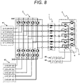
- FIG. 8 illustrates a connection example of a gate driver not illustrated in FIGS. 1 to 7 .
- the failure of the gate driver may cause the on and off states of the MOSFET driven by the gate driver to be unintentional. Therefore, it should be avoided that the plurality of MOSFETs that affect the operation continuation of the motor when the combination of the states is not determined should not be connected to the same gate driver.
- Examples of such a combination of MOSFETs include a MOSFET of an upper arm and a MOSFET of a lower arm of an inverter.
- the gate driver has a safety mechanism that reliably turns on or off the state of the MOSFET at the time of failure of the gate driver, and it is ensured that the safety mechanism functions with a sufficient probability, it is possible to connect a plurality of MOSFETs limited in combination of states to the same gate driver.
- the connection configuration of the gate driver will be described assuming that the gate driver does not have such a safety mechanism.
- the gate drivers are divided into a gate driver group 61 and a gate driver group 62 by the upper arm and the lower arm of the inverter. This is to prevent simultaneous turning on of the upper and lower arms that causes the through current from a failure of the gate driver.
- the third MOSFET group for regenerative current prevention is the same gate driver as the MOSFET group of the lower arm, and there is no problem. This is because even when the third MOSFET for regenerative current prevention is fixed in the off state, when the upper arm of the corresponding phase is turned off, the motor drive in the remaining four phases is not affected even if the state of the MOSFET of the lower arm is turned on or off.
- the gate drivers are desirably divided into gate drivers 63 and 64 in the first MOSFET group of M11 to M15 and the second MOSFET group of M21 to M25. If the first MOSFET group and the second MOSFET group are simultaneously turned off, both the neutral point 4 and the neutral point 5 are disconnected from the five-phase motor, so that the star connection is not secured, and the motor cannot be driven.
- By dividing the gate driver into the gate drivers 63 and 64 it is possible to ensure that any of the neutral points 4 and 5 always functions even when the gate driver fails.
- the electric power steering device includes a steering wheel, a rotation shaft attached to the steering wheel, a torque sensor attached to the rotation shaft, a steering mechanism, a microprocessor, and a five-phase motor, in addition to the motor drive device described above.
- the steering mechanism is steered by the rotation shaft to control the direction of the wheels. Steering force of the steering mechanism or the rotation shaft is assisted by a five-phase motor.
- the microprocessor serving as the inverter control unit controls the fourth MOSFET group of M41 to M45 and the fifth MOSFET group of M51 to M55 based on the output of the torque sensor.
- the five-phase motor is driven by a five-phase inverter including these switching elements.
- the predetermined MOSFET is turned off to cut off and separate the phase, and the operation of the five-phase motor is continued in the remaining four phases.
- the motor drive device is applied to the electric power steering device, but the present invention can also be applied to other devices such as a main motor of an electric vehicle.
- the neutral point switching unit is constituted by a semiconductor relay as in the related art
- two series MOSFETs are required for each semiconductor relay in order to prevent conduction due to a parasitic diode. Therefore, in the conventional motor drive device, the number of MOSFETs through which the current passes from the power supply to the ground is six in total.
- two neutral points are formed in parallel to divide the current into two, and a MOSFET is provided between each neutral point and the coil to form two MOSFETs in series, so that the number of the MOSFETs is equivalent to one in the neutral point switching unit. Therefore, in the motor drive device of the present embodiment, the number of MOSFETs through which the current passes from the power supply to the ground is four in total. Therefore, the total on-resistance of the MOSFETs when the motor is normally driven is reduced, and a highly efficient motor drive device with a small power loss can be realized.
- the one phase can be cut off and separated from the five-phase motor to continue the operation of the motor, and the motor can be operated using all the remaining four phases, so that the reduction of the torque at the time of failure can be suppressed.
- the MOSFET for regenerative current prevention is provided, even when a ground fault occurs in the wiring on the neutral point switching unit side, the regenerative current loop is blocked, and it is possible to prevent the motor from becoming difficult to control due to the brake torque.
- FIG. 9 is a circuit diagram illustrating an example of the motor drive device and the five-phase motor 1 according to the present embodiment.
- a neutral point switching unit 31 of the present embodiment is the same as that of the first embodiment in that two neutral points are connected in parallel to the five-phase motor 1, but is different from that of the first embodiment 1 in that the three MOSFETs are connected in two phases-two phases-one phase for each neutral point.
- each MOSFET will be described with respect to an example in which the ground fault occurs in the wiring of the coil W1, on the neutral point switching unit 31 side, which is one of the coils of the five-phase motor 1 in the present embodiment.
- the voltage of the coil W1 on the neutral point side is lower than the neutral point voltage, the coil W1 is cut off from the neutral point 5 and the neutral point 5 is protected from the ground fault by turning off the M2a, which is one in the second MOSFET group.
- the regenerative current loop of the coil W1 via the body diode of the M51 and the ground is cut off by turning off the M3a in the same phase as W1, and the generation of the brake torque can be prevented.
- the operation when one of the five phases fails, the operation can be continued as a three-phase motor using three of the remaining four phases.
- the present embodiment has an advantage that the total number of MOSFETs can be suppressed although the reduction of the torque is increased as compared with that of the first embodiment in which the operation can be continued as a four-phase motor even when one phase fails.
- the present invention is not limited to the embodiments described above, but includes various modifications.
- the above-described embodiments have been described in detail for easy understanding of the present invention, and the present invention is not necessarily limited to embodiments having all the configurations described.
- part of the configuration of a certain embodiment can be replaced with the configuration of another embodiment.
- the configuration of another embodiment can be added to the configuration of a certain embodiment. Further, it is possible to add, delete, and replace another configuration with respect to part of the configuration of each embodiment.
- the case of the five-phase motor is described as an example, but a motor having another number of phases may be used.
- a motor having another number of phases may be used.
- the motor cannot be driven in the star connection, and it is necessary to drive a neutral point with another inverter, and thus a motor with four or more phases is desirable.
Landscapes
- Engineering & Computer Science (AREA)
- Power Engineering (AREA)
- Control Of Ac Motors In General (AREA)
- Inverter Devices (AREA)
Abstract
Description
- The present invention relates to a motor drive device that drives a motor.
- In recent years, automatic driving of automobiles has been advanced with the benefit of development of machine training technology. In the case of a self-driving vehicle, it is assumed that the driver is absent or cannot drive a car. In such a situation, it is not possible to rely on the force of a human turning the steering wheel for steering of the vehicle, and the electric power steering device is responsible for all the steering forces. When the electric power steering device loses the steering force due to a failure, the vehicle cannot be steered. Therefore, the electric power steering device is required to have a fail-operational configuration in which the steering force is not lost even when a failure occurs. Similarly, a motor and an inverter that are responsible for a forward driving force of a vehicle of an electric vehicle is also required to maintain a driving force enough to move a vehicle on which a human rides at the time of failure to at least a safe shoulder, and a fail-operational configuration is required.
- In order to satisfy the fail-operational requirement as described above, a motor drive device is studied in which an inverter that drives a motor of a plurality of phases having a plurality of coils can continuously drive the motor even when a failure occurs in any phase.
-
PTL 1 discloses that "a motor in which coils of a plurality of phases of five or more phases are connected by star connection, an inverter that is connected to one end of each phase coil, converts DC power into AC power, and supplies the AC power to each phase of the motor, a power relay that is disposed on the other end side of each phase coil, and is configured to be able to cut off power supplied to coils of one or more phases among the coils of the plurality of phases of the motor by using a plurality of contacts inserted between the coils star-connected, and a control unit that controls driving of the motor by generating a control signal of the inverter are provided, and when one or more phases of the motor fail, the control unit opens the contact of the power relay corresponding to the failed phase, and drives three or more phases at substantially the same interval among the plurality of remaining phases". This configuration allows the motor to be continuously driven even when any phase of the motor fails. - PTL 1:
WO 2011/089656 - In the motor drive device described in
PTL 1, a power relay is used to separate a failed phase from other normal phases. However, in a case where each relay is configured by a semiconductor relay including a metal-oxide-semiconductor field-effect transistor (MOSFET), MOSFETs in two series are required in order to prevent conduction due to a parasitic diode. Therefore, in the motor drive device described inPTL 1, the number of MOSFETs connected in series via the current path from the power supply to the ground increases, and the on-resistance increases accordingly, and the power loss may increase. - An object of the present invention is to provide a motor drive device capable of not only continuing an operation by remaining phases when a certain phase among a plurality of phases fails, but also performing a highly efficient operation with a small power loss even in a normal state.
- In order to solve the above problems, the present invention is a motor drive device that drives a plurality of coils of a motor by an inverter, in which a first neutral point and a second neutral point different from the inverter are formed in advance by being connected in parallel to the plurality of coils, the motor drive device including: first MOSFETs between the first neutral point and coils connected, the first MOSFETs each having a cathode, of a body diode, on a coil side; and second MOSFETs between the second neutral point and coils connected, the second MOSFETs each having an anode, of a body diode, on a coil side.
- According to the present invention, it is possible to provide a motor drive device capable of not only continuing an operation by remaining phases when a certain phase among a plurality of phases fails but also performing a highly efficient operation with a small power loss even in a normal state.
-
- [
FIG. 1] FIG. 1 is a circuit diagram illustrating a motor drive device and a five-phase motor 1 according to a first embodiment. - [
FIG. 2] FIG. 2 is a diagram illustrating an on/off state of each MOSFET in a normal state in the first embodiment. - [
FIG. 3] FIG. 3 is a diagram illustrating an on/off state of each MOSFET in a case where an M45, which is one of upper arms of a five-phase inverter, has a short-circuit failure in the first embodiment. - [
FIG. 4] FIG. 4 is a diagram illustrating an on/off state of each MOSFET in a case where an M55, which is one of lower arms of a five-phase inverter, has a short-circuit failure in the first embodiment. - [
FIG. 5] FIG. 5 is a diagram illustrating an on/off state of each MOSFET in a case where an M35 which is one of the MOSFETs for regenerative current prevention has an open failure in in the first embodiment. - [
FIG. 6] FIG. 6 is a diagram illustrating an on/off state of each MOSFET in a case where W5, which is one of the coils of the five-phase motor 1, has a ground fault in the wiring on the neutral point side in the first embodiment. - [
FIG. 7] FIG. 7 is a diagram illustrating an on/off state of each MOSFET when W5, which is one of the coils of the five-phase motor 1, has a ground fault in the wiring on the inverter side in the first embodiment. - [
FIG. 8] FIG. 8 illustrates connection of gate drivers in the first embodiment. - [
FIG. 9] FIG. 9 is a circuit diagram illustrating a motor drive device and a five-phase motor 1 according to a second embodiment. - [
FIG. 10] FIG. 10 is a diagram illustrating on/off states of each MOSFET in a case where W1, which is one of the coils of the five-phase motor 1, has a ground fault in the wiring on the neutral point side in the second embodiment. - Hereinafter, embodiments of the present invention will be described with reference to the drawings. Note that the following embodiments are examples for carrying out the present invention, and the present invention is not limited thereto.
-
FIG. 1 is a circuit diagram illustrating an example of a motor drive device and a five-phase motor 1 according to the present embodiment. The motor drive device includes a five-phase inverter 2 to which a DC voltage is supplied from a power supply, and a neutralpoint switching unit 3 that forms a neutral point in advance for each phase of the five-phase motor 1. - First, the five-
phase inverter 2 includes a fourth MOSFET group of M41 to M45 and a fifth MOSFET group of M51 to M55. The fourth MOSFET group of M41 to M45 is a semiconductor switching element group that is on the high potential side of the five-phase inverter 2 and constitute the upper arms, and the fifth MOSFET group of M51 to M55 includes semiconductor switching elements that are on the low potential side of the five-phase inverter 2 and constitute the lower arms. The on/off of the switching element group is controlled by a control signal from an inverter control unit (not illustrated). - In addition, a third MOSFET group of M31 to M35 is provided between the five-
phase inverter 2 and the ground, and the third MOSFET group of M31 to M35 is connected in series with the respective phase outputs of the fifth MOSFET group of M51 to M55. - Here, the body diodes of the third MOSFET group of M31 to M35 are connected in a direction in which a current flows to the ground. That is, in each of the third MOSFET group of M31 to M35, the body diode is oriented such that the cathode is located on the ground side.
- Note that the body diode is assumed to be a parasitic diode inevitably formed due to the structure of the MOSFET, but may be a diode intentionally provided. As will be described later, the third MOSFET group of M31 to M35 plays a role of preventing a regenerative current from flowing through the five-
phase motor 1 when a ground fault occurs in the wiring of the five-phase motor 1 on the neutralpoint switching unit 3 side. - Next, the five-
phase motor 1 is a brushless motor including a rotor (not illustrated) and five-phase coils (W1 to W5) wound around a stator. One end of the coil of each phase is connected to the upper arm and the lower arm of each phase of the five-phase inverter 2. The other ends of the coil of respective phases are connected to the first MOSFET group of M11 to M15 and the second MOSFET group of M21 to M25 provided in the neutralpoint switching unit 3 to be described later. - The neutral
point switching unit 3 forms two neutral points in advance for the coil of each phase of the five-phase motor 1 via the first MOSFET group of M11 to M15 and the second MOSFET group of M21 to M25 connected in parallel. Then, when a certain phase of the five-phase inverter 2 fails, the neutralpoint switching unit 3 appropriately turns on/off each MOSFET group as described later according to a control signal from a neutral point control unit (not illustrated), and interrupts and separates the failed phase from the five-phase motor 1. - The first MOSFET group of M11 to M15 each has one end connected to the five-
phase motor 1, and the other end star-connected to each other to form aneutral point 4 which is a first neutral point. The second MOSFET group of M21 to M25 each has one end connected to the five-phase motor 1, and the other end star-connected to each other to form aneutral point 5 which is a second neutral point. Note that neither theneutral point 4 nor theneutral point 5 is connected to the power supply or the ground. - Here, the first MOSFET group of M11 to M15 each has a body diode that is oriented such that the cathode is located toward the coil of the five-
phase motor 1. On the other hand, the second MOSFET group of M21 to M25 each has a body diode that is oriented such that the anode is located toward the coil of the five-phase motor 1. - In addition, in the present embodiment, a failure detection unit (not illustrated) for detecting a failure of the five-
phase inverter 2 and each MOSFET is provided. As an example of the failure detection unit, it is conceivable to detect a failure of the MOSFET by monitoring a voltage between a drain and a source of the MOSFET and comparing the voltage with a predetermined threshold value. As another example, it is conceivable to detect the current flowing through each phase, detect that the current is excessive or insufficient by comparing the current with a predetermined threshold value, and detect the failure of the wiring and the five-phase motor 1. As the fault detection method, other widely known fault detection methods can be used. -
FIG. 2 is a diagram illustrating an on/off state of each MOSFET in a normal state in which no failure occurs. As illustrated inFIG. 2 , in a normal state, all of the MOSFETs (the first MOSFET group of M11 to M15 and the second MOSFET group of M21 to M25) in the neutralpoint switching unit 3 and all of the MOSFETs (the third MOSFET group of M31 to M35) for regenerative current prevention are turned on, and the device is operated as a five-phase inverter and a motor that are star-connected at theneutral point 4 and theneutral point 5. - Next, the operation of each MOSFET when a failure occurs will be described for each type of failure.
- First, the operation of each MOSFET when the inverter fails will be described for each type of failure. Here, the failure of the MOSFET of the inverter is roughly divided into a "short-circuit failure" and an "open failure". The "short-circuit failure" refers to a failure in which the switch is always in a conducting state due to a short circuit between the source and the drain of the MOSFET, and the "open failure" refers to a failure in which the switch is always in a cutoff state due to opening between the source and the drain of the MOSFET.
- As an example, an operation when the M45, which is one in the fourth MOSFET group constituting the upper arms of the five-
phase inverter 2, has a short-circuit failure will be described with reference toFIG. 3 . In this case, a battery voltage is continuously applied to the coil W5 connected to the M45, and an excessive DC current that does not contribute to the rotation of the motor continues to flow through the neutralpoint switching unit 3 to the coil W5 and the other coils W1 to W4, so that the operation of the motor cannot be continued. Therefore, when the short-circuit failure of the M45 is detected, the current flowing through the coil W5 is cut off by the following operation, and the motor operation is continued by the remaining coils W1 to W4. - When the short-circuit failure occurs in the M45, the voltage of the coil W5, connected to the M45, on the neutral point (neutral point switching unit 3) side has a value obtained by superimposing the induced voltage of the motor on the battery voltage. Since this voltage is higher than the neutral point voltage that is 1/2 of the battery voltage, the coil W5 is cut off from the
neutral point 4 by turning off the M45 corresponding to the phase of the M15 in which the short-circuit failure has occurred, and theneutral point 4 is protected from overvoltage. Note that M11 to M14 remain in an on state. On the other hand, even when the M25 is turned off, the current flows into theneutral point 5 by the body diode, but the current can be cut off by turning off all the M21 to M25. At this time, in the fifth MOSFET group constituting the lower arms, the M55 in the same phase as the M45 is also turned off. As a result, it is possible to continue the operation of the remaining coils W1 to W4 as a star-connected four-phase motor through theneutral point 4 while cutting off the coil W5 so that an unintended current does not flow. - As an example, when the open failure occurs in the M45, the current does not flow in the coil W5, and the operation can be continued as the four-phase motor by the remaining coils W1 to W4 even when each MOSFET of the neutral
point switching unit 3 remains ON. At this time, in the fifth MOSFET group constituting the lower arms, the M55 in the same phase as the M45 is turned off. - As an example, an operation when the M55, which is one in the fifth MOSFET group constituting the lower arms of the five-
phase inverter 2, has a short-circuit failure will be described with reference toFIG. 4 . In this case, the voltage of the coil W5, connected to the M55, on the five-phase inverter 2 side is fixed to the ground. Then, when a neutral point voltage is applied to the coil W5 on the neutral point, an excessive DC current continues to flow through the coil W5. Therefore, at this time, since the voltage of the coil W5 on the neutral point side is lower than the neutral point voltage, the coil W5 is cut off from theneutral point 5 by turning off the M55 corresponding to the phase of the M25 having the short-circuit failure. In this way, the voltage at theneutral point 5 is protected, and an unintended current flowing through the coil W5 is cut off. Note that M21 to M24 remain in an on state. On the other hand, even when the M15 is turned off, the current flows out from theneutral point 4 by the body diode, but the current can be cut off by turning off all the M11 to M15. At this time, in the fourth MOSFET group constituting the upper arms, the M55 in the same phase as the M45 is also turned off. As a result, it is possible to continue the operation of the remaining coils W1 to W4 as a star-connected four-phase motor through theneutral point 5 while cutting off the coil W5 so that an unintended current does not flow. - When the open failure occurs in the M55, the current does not flow in the coil W5, and the operation can be continued as the four-phase motor by the remaining coils W1 to W4 even when each MOSFET of the neutral
point switching unit 3 remains ON. At this time, in the fourth MOSFET group constituting the upper arms, the M55 in the same phase as the M45 is turned off. - When any in the third MOSFET group (M31 to M35) for regenerative current prevention has a short-circuit failure, the five-phase inverter and the motor operate normally without any problem. However, in a case where a failure such as a ground fault in the wiring on the neutral point switching unit side to be described later, which requires a measure to turn off the third MOSFET group, occurs thereafter, the measure cannot be taken. Therefore, a short-circuit failure of the third MOSFET group should be detected and a warning should be issued to encourage the administrator to repair the short-circuit failure.
- As an example, an operation when an open failure occurs in the M31 in the third MOSFET group (M35 to M35) for regenerative current prevention will be described with reference to
FIG. 5 . - In this case, the M35, of the upper arm, in the same phase as the M45 is turned off. As a result, the operation is continued as a four-phase motor by the remaining four phases excluding the phase of the M35 in which the open failure has occurred. At this time, among the MOSFETs of the neutral
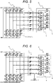
point switching unit 3, the M15 and the M25 corresponding to the phase of the M35 may be turned on or off. - Next, the operation of each MOSFET when the five-
phase motor 1 fails will be described. The failure of the five-phase motor 1 is roughly divided into a short-circuit failure and a disconnection failure of each of the coils W1 to W5, and a ground fault in which the wiring is short-circuited to the ground. Regarding the short-to-power fault in which the wiring is short-circuited to the power source, since all the housings of the motor and the inverter have the ground potential in the case of the vehicle, the probability of occurrence of the short-to-power fault is very low as compared with the case of the ground fault, so that it is possible to ignored the fault. - The short-circuit failure of the coil is a short-circuit that occurs in the coil, for example, a flaw or a defect of the coil coating, and the inductance of the coil is significantly reduced or the generated magnetic field is weakened. For the short-circuit failure of each of the coils W1 to W5, by turning off the MOSFETs of the upper arm and the lower arm of the inverter phase connected to the failed coil, the current to the failed coil is cut off, and the operation as the motor can be continued in the remaining four phases. As an example, in a case where a short-circuit failure occurs in the coil W5, the M45 and the M55 are turned off, so that an unintended current can be blocked from flowing through the coil W5.
- The disconnection failure of the coil occurs when an electric wire constituting the coil is broken due to fatigue caused by burning or mechanical vibration. When a disconnection failure of the coil occurs, a current cannot flow through the coil, and a magnetic force cannot be generated. As an example, when a disconnection failure occurs in the coil W5, the remaining coils W1 to W4 can continue the operation of the motor. It is not necessary to operate the MOSFET of the neutral
point switching unit 3 or the MOSFET for regenerative current prevention. - As an example, an operation when a ground fault occurs in the wiring of the coil W5, on the neutral point side, which is one of the coils of the five-
phase motor 1, will be described with reference toFIG. 6 . In this case, since the voltage of the coil W5 on the neutral point side is lower than the neutral point voltage, the coil W5 is cut off from theneutral point 5 and theneutral point 5 is protected from the ground fault by turning off the M25 corresponding to the phase in which the ground fault has occurred. Note that M21 to M24 remain in an on state. On the other hand, since theneutral point 4 is grounded, even when the M15 is turned off, the current flows out from theneutral point 4 by the body diode, but the current can be cut off by turning off all the M11 to M15. At this time, the M45 and the M55 that are MOSFETs of the five-phase inverter 2 connected to the coil W5 are also turned off. As a result, it is possible to continue the operation of the remaining coils W1 to W4 as a star-connected four-phase motor through theneutral point 5 while cutting off the coil W5 so that an unintended current does not flow. - In the third MOSFET group (M31 to M35) for regenerative current prevention, the regenerative current loop of the coil W5 via the body diode of the M55 and the ground is cut off by turning off the M35 in the same phase as W5, and the generation of the brake torque can be prevented.
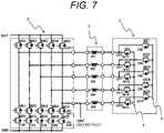
- As an example, an operation when a ground fault occurs in the wiring of the coil W5, on the five-
phase inverter 2 side, which is one of the coils of the five-phase motor 1, will be described with reference toFIG. 7 . Also in this case, since the voltage of the coil W5 on the neutral point side is lower than the neutral point voltage, the coil W5 is cut off from theneutral point 5 by turning off the M25 corresponding to the phase in which the ground fault has occurred. Note that M21 to M24 remain in an on state. - On the other hand, even when the M15 is turned off, the current flows out from the
neutral point 4 by the body diode, but the current can be cut off by turning off all of the M11 to M15. At this time, the M45 of the upper arm of the five-phase inverter 2 connected to the coil W5 is also turned off. As a result, it is possible to continue the operation of the remaining coils W1 to W4 as a star-connected four-phase motor through theneutral point 5 while cutting off the coil W5 so that an unintended current does not flow. Note that the M25 of the lower arm and the M35 for regenerative current prevention may be on or off. - Finally, the operation of each MOSFET when the neutral
point switching unit 3 fails will be described. The failure of the MOSFET constituting the neutralpoint switching unit 3 is roughly divided into a short-circuit failure and an open failure. As described above, since all of the first MOSFET group of M11 to M15 and the second MOSFET group of M21 to M25 are turned on in the normal state, there is no problem in continuing the operation of the motor even when a short-circuit failure occurs in any one of the MOSFETs. Even when an open failure occurs in any one of the MOSFETs, the neutralpoint switching unit 3 has the twoneutral points -
FIG. 8 illustrates a connection example of a gate driver not illustrated inFIGS. 1 to 7 . The failure of the gate driver may cause the on and off states of the MOSFET driven by the gate driver to be unintentional. Therefore, it should be avoided that the plurality of MOSFETs that affect the operation continuation of the motor when the combination of the states is not determined should not be connected to the same gate driver. - Examples of such a combination of MOSFETs include a MOSFET of an upper arm and a MOSFET of a lower arm of an inverter. However, when the gate driver has a safety mechanism that reliably turns on or off the state of the MOSFET at the time of failure of the gate driver, and it is ensured that the safety mechanism functions with a sufficient probability, it is possible to connect a plurality of MOSFETs limited in combination of states to the same gate driver. Here, the connection configuration of the gate driver will be described assuming that the gate driver does not have such a safety mechanism.
- First, the gate drivers are divided into a
gate driver group 61 and agate driver group 62 by the upper arm and the lower arm of the inverter. This is to prevent simultaneous turning on of the upper and lower arms that causes the through current from a failure of the gate driver. The third MOSFET group for regenerative current prevention is the same gate driver as the MOSFET group of the lower arm, and there is no problem. This is because even when the third MOSFET for regenerative current prevention is fixed in the off state, when the upper arm of the corresponding phase is turned off, the motor drive in the remaining four phases is not affected even if the state of the MOSFET of the lower arm is turned on or off. In the MOSFETs of the neutralpoint switching unit 3, the gate drivers are desirably divided intogate drivers neutral point 4 and theneutral point 5 are disconnected from the five-phase motor, so that the star connection is not secured, and the motor cannot be driven. By dividing the gate driver into thegate drivers neutral points - Here, a case where the above-described motor drive device is applied to an electric power steering device will be described. The electric power steering device includes a steering wheel, a rotation shaft attached to the steering wheel, a torque sensor attached to the rotation shaft, a steering mechanism, a microprocessor, and a five-phase motor, in addition to the motor drive device described above. The steering mechanism is steered by the rotation shaft to control the direction of the wheels. Steering force of the steering mechanism or the rotation shaft is assisted by a five-phase motor. The microprocessor serving as the inverter control unit controls the fourth MOSFET group of M41 to M45 and the fifth MOSFET group of M51 to M55 based on the output of the torque sensor. The five-phase motor is driven by a five-phase inverter including these switching elements. When a failure occurs in a certain phase, the predetermined MOSFET is turned off to cut off and separate the phase, and the operation of the five-phase motor is continued in the remaining four phases. As a result, as the electric power steering device, it is possible to ensure safety without hindering an operation on the motor by human power applied to the steering wheel, that is, an operation on the rotation shaft and the steering mechanism.
- In the present embodiment, the case where the motor drive device is applied to the electric power steering device is described, but the present invention can also be applied to other devices such as a main motor of an electric vehicle.
- Next, effects of the present embodiment will be described.
- When the neutral point switching unit is constituted by a semiconductor relay as in the related art, two series MOSFETs are required for each semiconductor relay in order to prevent conduction due to a parasitic diode. Therefore, in the conventional motor drive device, the number of MOSFETs through which the current passes from the power supply to the ground is six in total.
- On the other hand, as in the present embodiment, two neutral points are formed in parallel to divide the current into two, and a MOSFET is provided between each neutral point and the coil to form two MOSFETs in series, so that the number of the MOSFETs is equivalent to one in the neutral point switching unit. Therefore, in the motor drive device of the present embodiment, the number of MOSFETs through which the current passes from the power supply to the ground is four in total. Therefore, the total on-resistance of the MOSFETs when the motor is normally driven is reduced, and a highly efficient motor drive device with a small power loss can be realized.
- In addition, even when one phase of the five phases has some kind of failure, the one phase can be cut off and separated from the five-phase motor to continue the operation of the motor, and the motor can be operated using all the remaining four phases, so that the reduction of the torque at the time of failure can be suppressed.
- Furthermore, since the MOSFET for regenerative current prevention is provided, even when a ground fault occurs in the wiring on the neutral point switching unit side, the regenerative current loop is blocked, and it is possible to prevent the motor from becoming difficult to control due to the brake torque.
-
FIG. 9 is a circuit diagram illustrating an example of the motor drive device and the five-phase motor 1 according to the present embodiment. A neutralpoint switching unit 31 of the present embodiment is the same as that of the first embodiment in that two neutral points are connected in parallel to the five-phase motor 1, but is different from that of thefirst embodiment 1 in that the three MOSFETs are connected in two phases-two phases-one phase for each neutral point. - With reference to
FIG. 10 , the operation of each MOSFET will be described with respect to an example in which the ground fault occurs in the wiring of the coil W1, on the neutralpoint switching unit 31 side, which is one of the coils of the five-phase motor 1 in the present embodiment. In this case, since the voltage of the coil W1 on the neutral point side is lower than the neutral point voltage, the coil W1 is cut off from theneutral point 5 and theneutral point 5 is protected from the ground fault by turning off the M2a, which is one in the second MOSFET group. On the other hand, since theneutral point 4 is grounded, even when the M1a, which is one in the first MOSFET group, is turned off, a current flows out from theneutral point 4 by the body diode, but the current can be cut off by turning off all of the M1a to M1c. At this time, the M41 of the upper arm and the M51 of the lower arm in the five-phase inverter 21 connected to the coil W1 are also turned off. As a result, it is possible to continue the operation as a three-phase motor by the coils W3 to W5 through theneutral point 5 while cutting off the coil W1 so that an unintended current does not flow. In the MOSFET group (M3a to M3c) for regenerative current prevention, the regenerative current loop of the coil W1 via the body diode of the M51 and the ground is cut off by turning off the M3a in the same phase as W1, and the generation of the brake torque can be prevented. - In the present embodiment, when one of the five phases fails, the operation can be continued as a three-phase motor using three of the remaining four phases. The present embodiment has an advantage that the total number of MOSFETs can be suppressed although the reduction of the torque is increased as compared with that of the first embodiment in which the operation can be continued as a four-phase motor even when one phase fails.
- The present invention is not limited to the embodiments described above, but includes various modifications. The above-described embodiments have been described in detail for easy understanding of the present invention, and the present invention is not necessarily limited to embodiments having all the configurations described. Further, part of the configuration of a certain embodiment can be replaced with the configuration of another embodiment. In addition, the configuration of another embodiment can be added to the configuration of a certain embodiment. Further, it is possible to add, delete, and replace another configuration with respect to part of the configuration of each embodiment.
- For example, in the first and second embodiments described above, the case of the five-phase motor is described as an example, but a motor having another number of phases may be used. However, in the case of a three-phase motor, if one phase fails, the motor cannot be driven in the star connection, and it is necessary to drive a neutral point with another inverter, and thus a motor with four or more phases is desirable.
-
- 1 five-phase motor
- 2, 21 five-phase inverter
- 3, 31 neutral point switching unit
- 4 (first) neutral point
- 5 (second) neutral point
- 61, 62 gate driver group
- 63, 64 gate driver
- M11 to M12 first MOSFET group (upper arm of five-phase inverter)
- M21 to M25 second MOSFET group (lower arm of five-phase inverter)
- M33 to M35, M3a to M3c third MOSFET group (for regenerative current prevention)
- M41 to M45, M4a to M4c fourth MOSFET group (forming first neutral point)
- M51 to M55, M5a to M5c fifth MOSFET group (forming second neutral point)
- W1 to W5 coil
Claims (8)
- A motor drive device that drives a plurality of coils of a motor by an inverter, whereina first neutral point and a second neutral point that are different from the inverter are formed in advance by being connected in parallel to the plurality of coils,the motor drive device comprising:first MOSFETs between the first neutral point and coils connected, the first MOSFETs each having a cathode, of a body diode, on a coil side; andsecond MOSFETs between the second neutral point and coils connected, the second MOSFETs each having an anode, of a body diode, on a coil side.
- The motor drive device according to claim 1, further comprising third MOSFETs between the inverter and a ground, the third MOSFETs each having a cathode, of a body diode, on a ground side.
- The motor drive device according to claim 2, whereinwhen a ground fault occurs in a wiring, of a certain phase of the motor, on a neutral point side,a second MOSFET, of the second MOSFETs, connected to the certain phase is turned off, a third MOSFET, of the third MOSFETs, connected to the certain phase is turned off, anda first MOSFET, of the first MOSFETs, connected to the certain phase and first MOSFETs, of the first MOSFETs, connected to phases other than the certain phase are turned off.
- The motor drive device according to claim 1, whereinwhen a ground fault occurs in a wiring, of a certain phase of the motor, on an inverter side,a second MOSFET, of the second MOSFETs, connected to the certain phase is turned off, anda first MOSFET, of the first MOSFETs, connected to the certain phase and first MOSFETs, of the first MOSFETs, connected to phases other than the certain phase are turned off.
- The motor drive device according to claim 1, whereinwhen a short-circuit failure occurs in a certain phase of an upper arm of the inverter,a first MOSFET, of the first MOSFETs, connected to the certain phase is turned off, anda second MOSFET, of the second MOSFETs, corresponding to the certain phase and second MOSFETs, of the second MOSFETs, corresponding to phases other than the certain phase are turned off.
- The motor drive device according to claim 1, whereinwhen a short-circuit failure occurs in a certain phase of a lower arm of the inverter,a second MOSFET, of the second MOSFETs, connected to the certain phase is turned off, anda first MOSFET, of the first MOSFETs, corresponding to the certain phase and first MOSFETs, of the first MOSFETs, corresponding to phases other than the certain phase are turned off.
- The motor drive device according to claim 1, whereinthe motor is a motor having four or more phases, whereinthe motor drive device includes a first MOSFET of the first MOSFETs and a second MOSFET of the second MOSFETs for one coil, of the coils, of each phase, and whereinwhen a failure occurs in one phase of the four or more phases, the motor is consecutively operated with all phases other than the failed phase used.
- The motor drive device according to claim 1, wherein the first MOSFETs and the second MOSFETs are independently driven by respective gate drivers.
Applications Claiming Priority (2)
| Application Number | Priority Date | Filing Date | Title |
|---|---|---|---|
| JP2019183865A JP7280796B2 (en) | 2019-10-04 | 2019-10-04 | motor drive |
| PCT/JP2020/035553 WO2021065581A1 (en) | 2019-10-04 | 2020-09-18 | Motor drive device |
Publications (2)
| Publication Number | Publication Date |
|---|---|
| EP4040671A1 true EP4040671A1 (en) | 2022-08-10 |
| EP4040671A4 EP4040671A4 (en) | 2023-09-06 |
Family
ID=75337293
Family Applications (1)
| Application Number | Title | Priority Date | Filing Date |
|---|---|---|---|
| EP20873195.0A Pending EP4040671A4 (en) | 2019-10-04 | 2020-09-18 | MOTOR DRIVE DEVICE |
Country Status (4)
| Country | Link |
|---|---|
| EP (1) | EP4040671A4 (en) |
| JP (1) | JP7280796B2 (en) |
| CN (1) | CN114503426B (en) |
| WO (1) | WO2021065581A1 (en) |
Families Citing this family (2)
| Publication number | Priority date | Publication date | Assignee | Title |
|---|---|---|---|---|
| US11539322B1 (en) * | 2021-06-15 | 2022-12-27 | Hamilton Sundstrand Corporation | Fault tolerant motor including redundant wye winding and dual-state neutral leads |
| WO2024009671A1 (en) * | 2022-07-04 | 2024-01-11 | 株式会社Soken | Motor control device, motor control method, and motor control program |
Family Cites Families (12)
| Publication number | Priority date | Publication date | Assignee | Title |
|---|---|---|---|---|
| JP3861349B2 (en) * | 1996-12-25 | 2006-12-20 | 日本精工株式会社 | Electric power steering device |
| JP2007295658A (en) * | 2006-04-21 | 2007-11-08 | Nsk Ltd | Motor control device and electric power steering control device using the same |
| FR2936380B1 (en) * | 2008-09-24 | 2010-10-29 | Messier Bugatti | ELECTRIC ACTUATOR WHICH INCLUDES TWO CURRENT VOLTAGE INVERTERS SUPPLYING AN ELECTRICAL MACHINE AND WHICH IS RECONFIGURABLE IN THE PRESENCE OF A FAULT |
| FR2961361B1 (en) * | 2010-06-14 | 2013-07-12 | Hispano Suiza Sa | VOLTAGE INVERTER AND METHOD FOR CONTROLLING SUCH AS INVERTER |
| JP5678880B2 (en) * | 2011-12-28 | 2015-03-04 | トヨタ自動車株式会社 | Motor drive system and control method thereof |
| CN104185950B (en) * | 2012-03-22 | 2016-12-07 | 日立汽车系统株式会社 | Power conversion devices, electric power steering systems, electric vehicles, electronically controlled throttle valves, electric brakes |
| JP6096080B2 (en) * | 2013-08-02 | 2017-03-15 | 日立オートモティブシステムズ株式会社 | Motor drive control device |
| JP6286149B2 (en) * | 2013-08-02 | 2018-02-28 | 日立オートモティブシステムズ株式会社 | Power converter, electric power steering system, electric vehicle, electronic control throttle, electric brake |
| JP6717695B2 (en) | 2016-07-21 | 2020-07-01 | 株式会社Soken | Power converter |
| KR20190111118A (en) * | 2017-03-23 | 2019-10-01 | 히다치 오토모티브 시스템즈 가부시키가이샤 | Motor system |
| WO2018173424A1 (en) * | 2017-03-24 | 2018-09-27 | 日本電産株式会社 | Power conversion device, motor drive unit, and electric power steering device |
| WO2019159665A1 (en) * | 2018-02-13 | 2019-08-22 | 日本電産株式会社 | Power conversion device, motor module, and electric power steering device |
-
2019
- 2019-10-04 JP JP2019183865A patent/JP7280796B2/en active Active
-
2020
- 2020-09-18 CN CN202080069095.6A patent/CN114503426B/en active Active
- 2020-09-18 EP EP20873195.0A patent/EP4040671A4/en active Pending
- 2020-09-18 WO PCT/JP2020/035553 patent/WO2021065581A1/en not_active Ceased
Also Published As
| Publication number | Publication date |
|---|---|
| JP2021061672A (en) | 2021-04-15 |
| CN114503426B (en) | 2024-05-17 |
| JP7280796B2 (en) | 2023-05-24 |
| WO2021065581A1 (en) | 2021-04-08 |
| CN114503426A (en) | 2022-05-13 |
| EP4040671A4 (en) | 2023-09-06 |
Similar Documents
| Publication | Publication Date | Title |
|---|---|---|
| CN108473156B (en) | Electric power steering apparatus | |
| JP6979767B2 (en) | Motor drive and electric power steering | |
| US11283389B2 (en) | Motor system | |
| JP6302727B2 (en) | Electric motor control device | |
| US8981691B2 (en) | Motor drive apparatus | |
| JP6157752B2 (en) | Inverter device for driving multiphase AC motor | |
| CN103782469B (en) | Switch drive circuit, inverter unit, and power steering unit | |
| US10003294B2 (en) | Control apparatus of rotary electric machine and electric power steering apparatus using the same | |
| US20130200827A1 (en) | Motor control device, current control method applied to motor control device, and electric power steering device using motor control device | |
| CN106031021A (en) | Electric motor drive control device and drive control method | |
| CN110383676A (en) | Power inverter, motor drive unit and electric power steering apparatus | |
| WO2019053992A1 (en) | Power conversion device, motor module, and electric power steering device | |
| CN103460597A (en) | Motor control device | |
| WO2015019652A1 (en) | Drive control apparatus for electric motor | |
| WO2019054026A1 (en) | Power conversion device, motor module, and electric power steering device | |
| CN107431449B (en) | Motor control device | |
| US20220014140A1 (en) | Motor control system having redundant electric control unit | |
| JP2016096709A (en) | Motor drive device and electric power steering device | |
| EP4040671A1 (en) | Motor drive device | |
| CN103889768A (en) | Secure method for cutting off the power supply of an electric motor, and corresponding device | |
| CN112848900B (en) | Vehicle driving device | |
| JP7822298B2 (en) | Power Conversion Device | |
| CN116345409A (en) | Rectifier and method for operating an electrical machine | |
| JP2018129900A (en) | Motor control device and motor system | |
| JP2025084280A (en) | Drive control device for electric motor |
Legal Events
| Date | Code | Title | Description |
|---|---|---|---|
| STAA | Information on the status of an ep patent application or granted ep patent |
Free format text: STATUS: THE INTERNATIONAL PUBLICATION HAS BEEN MADE |
|
| PUAI | Public reference made under article 153(3) epc to a published international application that has entered the european phase |
Free format text: ORIGINAL CODE: 0009012 |
|
| STAA | Information on the status of an ep patent application or granted ep patent |
Free format text: STATUS: REQUEST FOR EXAMINATION WAS MADE |
|
| 17P | Request for examination filed |
Effective date: 20220414 |
|
| AK | Designated contracting states |
Kind code of ref document: A1 Designated state(s): AL AT BE BG CH CY CZ DE DK EE ES FI FR GB GR HR HU IE IS IT LI LT LU LV MC MK MT NL NO PL PT RO RS SE SI SK SM TR |
|
| DAV | Request for validation of the european patent (deleted) | ||
| DAX | Request for extension of the european patent (deleted) | ||
| REG | Reference to a national code |
Ref country code: DE Ref legal event code: R079 Free format text: PREVIOUS MAIN CLASS: H02P0027060000 Ipc: H02P0025220000 |
|
| A4 | Supplementary search report drawn up and despatched |
Effective date: 20230803 |
|
| RIC1 | Information provided on ipc code assigned before grant |
Ipc: H02P 29/028 20160101ALN20230728BHEP Ipc: H02M 7/5387 20070101ALN20230728BHEP Ipc: H02M 1/32 20070101ALN20230728BHEP Ipc: H02M 7/48 20070101ALI20230728BHEP Ipc: H02P 27/06 20060101ALI20230728BHEP Ipc: H02P 25/22 20060101AFI20230728BHEP |
|
| STAA | Information on the status of an ep patent application or granted ep patent |
Free format text: STATUS: EXAMINATION IS IN PROGRESS |
|
| 17Q | First examination report despatched |
Effective date: 20250205 |
|
| RAP3 | Party data changed (applicant data changed or rights of an application transferred) |
Owner name: ASTEMO, LTD. |
|
| GRAP | Despatch of communication of intention to grant a patent |
Free format text: ORIGINAL CODE: EPIDOSNIGR1 |
|
| STAA | Information on the status of an ep patent application or granted ep patent |
Free format text: STATUS: GRANT OF PATENT IS INTENDED |
|
| RIC1 | Information provided on ipc code assigned before grant |
Ipc: H02P 25/22 20060101AFI20260326BHEP Ipc: H02P 27/06 20060101ALI20260326BHEP Ipc: H02M 7/48 20070101ALI20260326BHEP Ipc: H02M 1/32 20070101ALN20260326BHEP Ipc: H02M 7/5387 20070101ALN20260326BHEP Ipc: H02P 29/028 20160101ALN20260326BHEP |