EP4040654A1 - Manufacturing method of rotor core and manufacturing system of rotor core - Google Patents
Manufacturing method of rotor core and manufacturing system of rotor core Download PDFInfo
- Publication number
- EP4040654A1 EP4040654A1 EP20873103.4A EP20873103A EP4040654A1 EP 4040654 A1 EP4040654 A1 EP 4040654A1 EP 20873103 A EP20873103 A EP 20873103A EP 4040654 A1 EP4040654 A1 EP 4040654A1
- Authority
- EP
- European Patent Office
- Prior art keywords
- resin material
- resin
- magnet holding
- holding portion
- jig
- Prior art date
- Legal status (The legal status is an assumption and is not a legal conclusion. Google has not performed a legal analysis and makes no representation as to the accuracy of the status listed.)
- Pending
Links
Images



Classifications
-
- H—ELECTRICITY
- H02—GENERATION; CONVERSION OR DISTRIBUTION OF ELECTRIC POWER
- H02K—DYNAMO-ELECTRIC MACHINES
- H02K15/00—Processes or apparatus specially adapted for manufacturing, assembling, maintaining or repairing of dynamo-electric machines
- H02K15/12—Impregnating, moulding insulation, heating or drying of windings, stators, rotors or machines
-
- B—PERFORMING OPERATIONS; TRANSPORTING
- B29—WORKING OF PLASTICS; WORKING OF SUBSTANCES IN A PLASTIC STATE IN GENERAL
- B29C—SHAPING OR JOINING OF PLASTICS; SHAPING OF MATERIAL IN A PLASTIC STATE, NOT OTHERWISE PROVIDED FOR; AFTER-TREATMENT OF THE SHAPED PRODUCTS, e.g. REPAIRING
- B29C45/00—Injection moulding, i.e. forcing the required volume of moulding material through a nozzle into a closed mould; Apparatus therefor
- B29C45/14—Injection moulding, i.e. forcing the required volume of moulding material through a nozzle into a closed mould; Apparatus therefor incorporating preformed parts or layers, e.g. injection moulding around inserts or for coating articles
- B29C45/14065—Positioning or centering articles in the mould
-
- B—PERFORMING OPERATIONS; TRANSPORTING
- B29—WORKING OF PLASTICS; WORKING OF SUBSTANCES IN A PLASTIC STATE IN GENERAL
- B29C—SHAPING OR JOINING OF PLASTICS; SHAPING OF MATERIAL IN A PLASTIC STATE, NOT OTHERWISE PROVIDED FOR; AFTER-TREATMENT OF THE SHAPED PRODUCTS, e.g. REPAIRING
- B29C45/00—Injection moulding, i.e. forcing the required volume of moulding material through a nozzle into a closed mould; Apparatus therefor
- B29C45/14—Injection moulding, i.e. forcing the required volume of moulding material through a nozzle into a closed mould; Apparatus therefor incorporating preformed parts or layers, e.g. injection moulding around inserts or for coating articles
- B29C45/14778—Injection moulding, i.e. forcing the required volume of moulding material through a nozzle into a closed mould; Apparatus therefor incorporating preformed parts or layers, e.g. injection moulding around inserts or for coating articles the article consisting of a material with particular properties, e.g. porous, brittle
- B29C45/14811—Multilayered articles
-
- H—ELECTRICITY
- H02—GENERATION; CONVERSION OR DISTRIBUTION OF ELECTRIC POWER
- H02K—DYNAMO-ELECTRIC MACHINES
- H02K15/00—Processes or apparatus specially adapted for manufacturing, assembling, maintaining or repairing of dynamo-electric machines
- H02K15/02—Processes or apparatus specially adapted for manufacturing, assembling, maintaining or repairing of dynamo-electric machines of stator or rotor bodies
- H02K15/03—Processes or apparatus specially adapted for manufacturing, assembling, maintaining or repairing of dynamo-electric machines of stator or rotor bodies having permanent magnets
-
- B—PERFORMING OPERATIONS; TRANSPORTING
- B29—WORKING OF PLASTICS; WORKING OF SUBSTANCES IN A PLASTIC STATE IN GENERAL
- B29K—INDEXING SCHEME ASSOCIATED WITH SUBCLASSES B29B, B29C OR B29D, RELATING TO MOULDING MATERIALS OR TO MATERIALS FOR MOULDS, REINFORCEMENTS, FILLERS OR PREFORMED PARTS, e.g. INSERTS
- B29K2705/00—Use of metals, their alloys or their compounds, for preformed parts, e.g. for inserts
- B29K2705/08—Transition metals
- B29K2705/12—Iron
-
- B—PERFORMING OPERATIONS; TRANSPORTING
- B29—WORKING OF PLASTICS; WORKING OF SUBSTANCES IN A PLASTIC STATE IN GENERAL
- B29K—INDEXING SCHEME ASSOCIATED WITH SUBCLASSES B29B, B29C OR B29D, RELATING TO MOULDING MATERIALS OR TO MATERIALS FOR MOULDS, REINFORCEMENTS, FILLERS OR PREFORMED PARTS, e.g. INSERTS
- B29K2995/00—Properties of moulding materials, reinforcements, fillers, preformed parts or moulds
- B29K2995/0003—Properties of moulding materials, reinforcements, fillers, preformed parts or moulds having particular electrical or magnetic properties, e.g. piezoelectric
- B29K2995/0008—Magnetic or paramagnetic
-
- B—PERFORMING OPERATIONS; TRANSPORTING
- B29—WORKING OF PLASTICS; WORKING OF SUBSTANCES IN A PLASTIC STATE IN GENERAL
- B29L—INDEXING SCHEME ASSOCIATED WITH SUBCLASS B29C, RELATING TO PARTICULAR ARTICLES
- B29L2031/00—Other particular articles
- B29L2031/748—Machines or parts thereof not otherwise provided for
- B29L2031/7498—Rotors
-
- Y—GENERAL TAGGING OF NEW TECHNOLOGICAL DEVELOPMENTS; GENERAL TAGGING OF CROSS-SECTIONAL TECHNOLOGIES SPANNING OVER SEVERAL SECTIONS OF THE IPC; TECHNICAL SUBJECTS COVERED BY FORMER USPC CROSS-REFERENCE ART COLLECTIONS [XRACs] AND DIGESTS
- Y02—TECHNOLOGIES OR APPLICATIONS FOR MITIGATION OR ADAPTATION AGAINST CLIMATE CHANGE
- Y02T—CLIMATE CHANGE MITIGATION TECHNOLOGIES RELATED TO TRANSPORTATION
- Y02T10/00—Road transport of goods or passengers
- Y02T10/60—Other road transportation technologies with climate change mitigation effect
- Y02T10/64—Electric machine technologies in electromobility
Definitions
- the present invention relates to a rotor core manufacturing method and a rotor core manufacturing system.
- Rotor core manufacturing methods are conventionally known. Such a rotor core manufacturing method and rotor core manufacturing system is disclosed in, for example, Japanese Patent No. 6180569 ( JP 6180569 ).
- JP 6180569 a permanent magnet is inserted in each of a plurality of magnet insertion holes in a stacked rotor core in which a plurality of core pieces is stacked together, and the permanent magnet is resin-sealed in each magnet insertion hole.
- resin is heated and melted, and the molten resin is supplied into the magnet insertion holes in the stacked rotor core.
- the stacked rotor core that has the permanent magnets inserted in the magnet insertion holes are transferred above a lower die. It is noted that an upper die is set above the stacked rotor core.
- raw materials for thermosetting resin are supplied into pots that are provided to the upper die, and the raw materials are heated by heating means. As the raw materials are heated, the viscosity thereof decreases.
- the stacked rotor core is pressed against the upper die. Then, the raw materials that have the decreased viscosity (that have fluidized) are supplied to fill the magnet insertion holes via flow channels that are provided in the upper die and that connect the pots to the magnet insertion holes.
- the stacked rotor core (the raw materials for thermosetting resin) is heated by heating means that are provided separately to the upper die and the lower die, so that the thermosetting resin is cured.
- the permanent magnets are fixed (resin-sealed) in the magnet insertion holes.
- the thermosetting resin may be cured by heating the raw materials that have the decreased viscosity using the heating means, while the stacked rotor core is held between the upper die and the lower die.
- Patent Document 1 JP 6180569
- thermosetting resin may be cured by being heated by the heating means provided separately to the upper die and the lower die, while the stacked rotor core is held between the upper die and the lower die. For this reason, when the thermosetting resin charged in the magnet insertion holes is cured, the thermosetting resin remaining in the flow channels that connect the pots to the magnet insertion holes may also be heated and cured. Therefore, in order to supply thermosetting resin to fill magnet insertion holes next time, it is necessary to remove the cured thermosetting resin remaining in the flow channels beforehand. That is, the removed cured thermosetting resin is incapable of being used for resin-sealing of permanent magnets. This presents a problem in that the yield (the ratio of a raw material used for resin-sealing to the quantity of a supplied raw material) of a raw material for thermosetting resin (a resin material) decreases.
- the present invention addresses a problem like the one described above.
- One purpose of the present invention is to provide a rotor core manufacturing method and a rotor core manufacturing system that are capable of increasing the yield of a resin material.
- a rotor core manufacturing method includes: a step of preparing a stacked core in which a plurality of electrical steel sheets is stacked together and that has a magnet holding portion extending in a stack direction of the electrical steel sheets; a step of placing a permanent magnet in the magnet holding portion; a step of mounting the stacked core to a jig that presses the stacked core in the stack direction; a step of injecting a resin material in a molten state into the magnet holding portion by a resin injection portion that is included in a resin injection apparatus, while the stacked core remains pressed by the jig and the permanent magnet remains inserted in the magnet holding portion; a step of retracting the resin injection portion of the resin injection apparatus relative to the stacked core that remains pressed by the jig, after the step of injecting the resin material into the magnet holding portion, while maintaining the molten state of the resin material that is stored in the resin injection portion, and a step of curing the
- the rotor core manufacturing method includes: the step of retracting the resin injection portion of the resin injection apparatus relative to the stacked core that remains pressed by the jig, after the step of injecting the resin material into the magnet holding portion, while maintaining the molten state of the resin material stored in the resin injection portion; and the step of curing the resin material in the magnet holding portion, after the step of relatively retracting the resin injection portion, by heating the stacked core that has the resin material injected in the magnet holding portion and that remains pressed by the jig.
- a rotor core manufacturing system is a system of manufacturing a rotor provided with a stacked core in which a plurality of electrical steel sheets is stacked together, the stacked core having a magnet holding portion extending in a stack direction of the plurality of electrical steel sheets.
- the system includes: a jig that presses, in the stack direction, the stacked core that has a permanent magnet in the magnet holding portion, and a resin injection apparatus that injects a resin material in a molten state into the magnet holding portion by a resin injection portion, while the stacked core remains pressed by the jig and the permanent magnet remains in the magnet holding portion.
- the system is structured such that the resin injection portion is retracted relative to the stacked core that remains pressed by the jig, while the resin material stored in the resin injection portion is maintained in the molten state, after injection of the resin material into the magnet holding portion, and such that the resin material in the magnet holding portion is cured by heating the stacked core that has the resin material injected in the magnet holding portion and that remains pressed by the jig.
- the rotor manufacturing system is structured such that the resin injection portion is retracted relative to the stacked core that remains pressed by the jig, after injection of the resin material into the magnet holding portion, while the resin material stored in the resin injection apparatus is maintained in a molten state, and such that the resin material in the magnet holding portion is cured by heating the stacked core that has the resin material injected in the magnet holding portion and that remains pressed by the jig.
- the resin injection portion of the resin injection apparatus is already retracted relative to the stacked core when the resin material is cured, the resin material stored in the resin injection portion does not cure.
- the present invention is capable of increasing the yield of a resin material.
- FIGS. 1 to 7 a manufacturing method for a rotor core 4 and a manufacturing system 200 for the rotor core 4, according to the present embodiment, are described.
- an "axial direction” refers to directions along a rotational axis C1 of a rotor 1 (the rotor core 4) and corresponds to a direction Z illustrated in the drawings.
- a "radial direction” refers to a radial direction (a direction R1 or a direction R2) of the rotor 1 (the rotor core 4)
- a “circumferential direction” refers to a circumferential direction (a direction E1 or a direction E2) of the rotor 1 (the rotor core 4).
- the rotating electrical machine 100 is structured as an inner-rotor-type rotating electrical machine.
- a shaft 3 is located radially inside the rotor 1.
- the shaft 3 is coupled to, for example, an engine and an axle via a member that transmits a rotational force, such as a gear.
- the rotating electrical machine 100 is structured as a motor, a generator, or a motor-generator and is structured to be mounted on a vehicle.
- the rotor core 4 is provided with a stacked core 4d in which a plurality of electrical steel sheets 4a (refer to FIG. 3 ) is stacked together and that has a magnet holding portion 10 that is a through hole extending in the stack direction of the electrical steel sheets 4a. Further, the rotor core 4 is provided with a permanent magnet 5 that is inserted in the magnet holding portion 10 of the stacked core 4d.
- a plurality of (32 in the present embodiment) magnet holding portions 10 is provided in the rotor core 4. That is, the rotating electrical machine 100 is structured as an interior permanent magnet motor (IPM motor). Two of the magnet holding portions 10 that are adjacent to each other are arranged in a V-shape. It is noted that the arrangement of the magnet holding portions 10 is not limited to this.
- the stator 2 includes a stator core 2a and a coil 2b that is mounted in the stator core 2a.
- the stator core 2a is structured, for example, by stacking a plurality of electrical steel sheets (silicon steel sheets) together in the axial direction in such a manner as to allow magnetic flux to pass therethrough.
- the coil 2b is coupled to an external power supply portion and is structured to be supplied with electric power (e.g., three-phase alternating current power).
- the coil 2b is structured to generate a magnetic field by being supplied with electric power.
- the rotor 1 and the shaft 3 are structured to rotate with respect to the stator 2 together with driving of an engine or the like, even when no electric power is supplied to the coil 2b.
- FIG. 1 illustrates only part of the coil 2b, the coil 2b is mounted over the entire circumference of the stator core 2a.
- the permanent magnet 5 is rectangular in cross section perpendicular to the axial direction of the rotor core 4.
- the permanent magnet 5 is structured to have a direction of magnetization (a magnetized direction) along the short sides thereof.
- the rotor core 4 is provided with a resin material 6 that is charged in the magnet holding portions 10.
- the resin material 6 is provided to fix the permanent magnets 5 that are placed in the magnet holding portions 10.
- FIGS. 2 to 4 the structure of a jig 20 according to the present embodiment is described. It is noted that the description below describes the structure of the jig 20 in a state where the stacked core 4d is already mounted to the jig 20.
- the jig 20 includes an upper plate 21, a pressing spring 22, a pressing plate 23, a lower plate 24, a thermal insulator 25, a positioning plate 26, and a clamping member 27. It is noted that the upper plate 21, the pressing plate 23, the lower plate 24, and the positioning plate 26 are all made of stainless steel (SUS).
- the upper plate 21 has a through hole 21a in the center thereof and is annularly shaped. Further, the upper plate 21 includes a plurality of resin injection holes 21b.
- the resin injection holes 21b are provided such that injection nozzles 122 of a resin injection apparatus 103 that is described later are insertable therein. Specifically, the resin injection holes 21b are provided in such a manner as to individually overlap the plurality of (32 in the present embodiment) magnet holding portions 10. It is noted that the resin injection holes 21b are one example of a "hole portion" recited in the claims.
- the pressing spring 22 is provided in such a manner as to couple the upper plate 21 and the pressing plate 23 together.
- a plurality of pressing springs 22 is provided at equal angular intervals in the circumferential direction when viewed in the direction of the rotational axis C1.
- four pressing springs 22 are provided.
- Each of the plurality of pressing springs 22 is provided at a position that overlaps the stacked core 4d, when viewed from above (from the direction Z1), in a state where the stacked core 4d is already mounted to the jig 20.
- the pressing plate 23 is located on a top surface 4b of the stacked core 4d.
- the pressing plate 23 is provided in such a manner as to press the top surface 4b of the stacked core 4d by using biasing forces of the pressing springs 22.
- the pressing plate 23 has a through hole 23a in the center thereof and is annularly shaped.
- the pressing plate 23 includes a plurality of resin injection holes 23b.
- the plurality of resin injection holes 23b is provided at positions that overlap the plurality of resin injection holes 21b in the upper plate 21 when viewed from above (from the direction Z1). It is noted that the resin injection holes 23b are one example of the "hole portion" recited in the claims.
- the stacked core 4d is placed (put) on the lower plate 24. That is, the lower plate 24 is in contact with a bottom surface 4c of the stacked core 4d.
- the lower plate 24 has a through hole 24a in the center thereof and is annularly shaped. Further, the lower plate 24 includes a plurality of (three in the present embodiment) cut portions 24b. The plurality of cut portions 24b is provided on the inner circumference of the through hole 24a at almost equal angular intervals (refer to FIG. 4 ) in the circumferential direction when viewed in the direction of the rotational axis C1.
- the plurality of cut portions 24b is provided with L-shaped positioning portions 24c.
- the radial and circumferential positions of the stacked core 4d relative to the lower plate 24 are decided by the plurality of positioning portions 24c.
- the positioning portions 24c are fixed (fastened) by fastening bolts 24d to the lower plate 24.
- the thermal insulator 25 is provided in such a manner as to be held between the lower plate 24 and the positioning plate 26.
- the thermal insulator 25 has a through hole 25a in the center thereof and is annularly shaped.
- the thermal insulator 25 is made of resin.
- the positioning plate 26 is provided below the lower plate 24 (in the direction Z2).
- the clamping member 27 has a U-shape and is provided in such a manner as to clamp the upper plate 21 and the lower plate 24 together.
- the stacked core 4d is held and pressed between the upper plate 21 and the lower plate 24 in a vertical direction (in the direction Z).
- the upper plate 21 holds and presses the stacked core 4d indirectly via the pressing plate 23 in conjunction with the lower plate 24.
- the stacked core 4d is fixed to the jig 20.
- a plurality of (four in the present embodiment) clamping members 27 is provided.
- the plurality of clamping members 27 is provided at almost equal angular intervals (i.e., at intervals of 90 degrees) in the circumferential direction when viewed in the direction of the rotational axis C1.
- the manufacturing system 200 for the rotor core 4 is provided with an assembly apparatus 101, a preheating heater apparatus 102, the resin injection apparatus 103, and a curing heater apparatus 104. Further, the manufacturing system 200 for the rotor core 4 is provided with a transfer conveyor 108 that transfers the stacked core 4d. It is noted that the assembly apparatus 101, the preheating heater apparatus 102, the resin injection apparatus 103, and the curing heater apparatus 104 are apparatuses that are separate from each other.
- the assembly apparatus 101 is structured to mount (assemble) the stacked core 4d to the jig 20. Specifically, the assembly apparatus 101 is structured to mount the stacked core 4d to the jig 20 and to mount the permanent magnets 5 in the magnet holding portions 10.
- the preheating heater apparatus 102 is structured to perform preheating by heating the stacked core 4d. Specifically, the preheating heater apparatus 102 is structured to perform preheating by heating the stacked core 4d that remains mounted to the jig 20 at a temperature that is greater than or equal to a first temperature T1 (e.g., 50°C) and less than a second temperature T2 (e.g., 120°C). It is noted that the first temperature T1 is a temperature at which the resin material 6 melts (a temperature at which the melting starts). On the other hand, the second temperature T2 is a temperature at which the resin material 6 cures (thermally cures) (a temperature at which the curing (the thermal curing) starts) and that is greater than the first temperature T1.
- a first temperature T1 e.g., 50°C
- T2 e.g. 120°C
- the first temperature T1 is a temperature at which the resin material 6 melts (a temperature at which the melting starts).
- the second temperature T2
- the resin injection apparatus 103 is structured to inject the resin material 6 into the magnet holding portions 10. Specifically, the resin injection apparatus 103 is structured to inject the resin material 6 that has been melted at the first temperature T1 or greater into the magnet holding portions 10, while the stacked core 4d remains mounted to the jig 20 and the permanent magnets 5 remain inserted in the magnet holding portions 10. Details of the structure of the resin injection apparatus 103 are described later.
- the curing heater apparatus 104 is structured to cure the resin material 6 in the magnet holding portions 10 by heating the stacked core 4d. Specifically, the curing heater apparatus 104 is structured to cure the resin material 6 in the magnet holding portions 10 by heating the stacked core 4d that remains mounted to the jig 20 and that has the resin material 6 injected in the magnet holding portions 10, at a temperature greater than or equal to the second temperature T2 that is a temperature at which the resin material 6 cures.
- the resin injection apparatus 103 includes a resin injection portion 103a.
- the resin material 6 is structured to melt at the first temperature T1 and to cure at the second temperature T2 greater than the first temperature T1.
- a resin material 6 synthetic resin material
- JP 2000-239642 A Japanese Unexamined Patent Application Publication No. 2000-239642
- the resin material 6 includes a reactive hot melt adhesive composition that contains 10% to 100% of a first compound having at least 100 eq/T of uretdione rings, 0% to 90% of a second compound having active hydrogen groups at molecular ends, and 0% to 90% of a third compound having glycidyl groups, and the reactive hot melt adhesive composition is characterized in that none of the first to third compounds have isocyanate groups at molecular ends.
- the resin material 6 disclosed in JP 2000-239642 A is solid (in the form of flakes, pellets, powder, etc.) at ordinary temperatures, but melts (softens) when heated until the temperature of the resin material 6 reaches the first temperature T1. Further, this resin material 6 does not cure while it is maintained at the first temperature T1. On the other hand, this resin material 6 cures when it reaches the second temperature T2 greater than the first temperature T1.
- a flow channel 121 where the resin material 6 flows is provided within the resin injection portion 103a.
- the flow channel 121 branches into a plurality of flow channels 121a toward the stacked core 4d.
- Flow channels 121b of the flow channel 121 on the side closer to the stacked core 4d are provided at positions corresponding to the magnet holding portions 10 of the stacked core 4d.
- the resin injection portion 103a is provided with the injection nozzles 122.
- the injection nozzles 122 are provided on the distal-end side (the flow channels 121b) of the flow channel 121.
- the resin material 6 stored in the flow channel 121 is injected into the magnet holding portions 10 of the stacked core 4d from the injection nozzles 122 of the resin injection portion 103a.
- the flow channels 121b are provided with stop valves 123.
- the stop valves 123 change to an open state.
- the stop valves 123 change to a closed state. It is noted that the stop valves 123 are one example of an "interrupting portion" recited in the claims.
- a heating device 124 is provided outside the resin injection portion 103a.
- the heating device 124 heats the resin injection portion 103a such that the temperature of the resin material 6 stored within the resin injection portion 103a reaches the first temperature T1.
- step S1 a step of preparing the stacked core 4d is performed.
- the stacked core 4d is formed by stacking a plurality of electrical steel sheets 4a together.
- the magnet holding portions 10 that extend in the stack direction of the electrical steel sheets 4a are formed in the stacked core 4d by press working.
- step S2 steps of mounting the stacked core 4d to the jig 20 are performed in the assembly apparatus 101.
- the stacked core 4d is mounted to the jig 20 such that the stacked core 4d is held and pressed in the vertical direction (in the direction Z) between the upper plate 21 (the pressing plate 23) and the lower plate 24.
- a step of placing (putting) the stacked core 4d on the lower plate 24 is performed.
- a step of placing the permanent magnets 5 in the magnet holding portions 10 are performed while the stacked core 4d remains on the lower plate 24.
- the steps of mounting the stacked core 4d to the jig 20 are steps of mounting the stacked core 4d to the jig 20 that is provided with the thermal insulator 25.
- step S3 a step of preheating the stacked core 4d is performed.
- the preheating heater apparatus 102 performs the preheating step by heating the stacked core 4d that remains mounted to the jig 20, at the temperature that is greater than or equal to the first temperature T1 and less than the second temperature T2.
- step S4 a step of injecting the resin material 6 into the magnet holding portions 10 is performed.
- the resin injection portion 103a included in the resin injection apparatus 103 injects the resin material 6 that is in a molten state into the magnet holding portions 10, while the stacked core 4d remains pressed by the jig 20 and the permanent magnets 5 remain inserted in the magnet holding portions 10.
- the resin material 6 that is in a molten state is injected while the temperature of the resin material 6 is greater than or equal to the first temperature T1 and less than the second temperature T2. It is noted that in the step of injecting the resin material 6, the resin material 6 that is solid at ordinary temperatures is melted at the first temperature T1, and then the molten resin material 6 is injected into the magnet holding portions 10.
- the resin injection portion 103a is stationary.
- the stacked core 4d that remains pressed by the jig 20 is moved up toward the resin injection portion 103a that remains stationary.
- the injection nozzles 122 of the resin injection portion 103a are inserted into the magnet holding portions 10 that have the permanent magnets 5 therein.
- the stop valves 123 are changed to the open state so that the resin material 6 is supplied to fill the magnet holding portions 10.
- the stop valves 123 are changed to a closed state.
- the resin material 6 in the step of injecting the resin material 6, the resin material 6 is injected into the magnet holding portions 10 while pressure is applied to the resin material 6.
- the pressure applied to the resin material 6 increases above a predetermined threshold.
- the injection of the resin material 6 is stopped. For example, after the pressure applied to the resin material 6 increases above the predetermined threshold (e.g., about 8.5 Mpa), the increased pressure is maintained for about five seconds. It is noted that of all the resin material 6 stored in the resin injection portion 103a, only the necessary amount of the resin material 6 is injected directly into the magnet holding portions 10.
- the resin material 6 may be injected into the magnet holding portions 10 while the tips of the injection nozzles 122 are in abutment with the stacked core 4d. Alternatively, the resin material 6 may be injected into the magnet holding portions 10 while the tips pf the injection nozzles 122 are in abutment with the jig 20 (while the injection nozzles 122 are separated from the stacked core 4d).
- the resin material 6 is injected by the resin injection portion 103a into the magnet holding portions 10 through the resin injection holes 21b and the resin injection holes 23b provided in the jig 20 that presses the stacked core 4d. Specifically, the injection nozzles 122 of the resin injection portion 103a are inserted through the resin injection holes 21b and the resin injection holes 23b. Then, the resin material 6 is injected into the magnet holding portions 10 from the injection nozzles 122 inserted through the resin injection holes 21b and the resin injection holes 23b. That is, according to the present embodiment, in the step of injecting the resin material 6, the resin material 6 is injected into the magnet holding portions 10 from above.
- the thermal insulator 25 suppresses the transfer of heat of the resin material 6 to the positioning plate 26 of the jig 20.
- step S5 after the step of injecting the resin material 6 into the magnet holding portions 10, the resin injection portion 103a of the resin injection apparatus 103 is retracted relative to the stacked core 4d that remains pressed by the jig 20, while the resin material 6 stored in the resin injection portion 103a is maintained in a molten state. That is, the resin injection portion 103a is retracted relative to the stacked core 4d while the heating is maintained such that the temperature of the resin material 6 stored in the resin injection portion 103a is equal to the first temperature T1.
- the resin injection portion 103a in the step of relatively retracting the resin injection portion 103a after the resin material 6 is injected by the resin injection portion 103a into the magnet holding portions 10, the resin injection portion 103a is relatively retracted while the stop valves 123 provided to the resin injection portion 103a interrupt the injection of the resin material 6 from the resin injection portion 103a (i.e., while the stop valves 123 are in a closed state). Furthermore, in the step of relatively retracting the resin injection portion 103a, the resin injection portion 103a is relatively retracted while the pressure applied to the resin material 6 is less than the pressure that is applied to the resin material 6 in the step of injecting the resin material 6.
- the resin injection portion 103a in the step of relatively retracting the resin injection portion 103a, the resin injection portion 103a is relatively retracted by moving the stacked core 4d away from the resin injection portion 103a.
- the resin injection portion 103a is moved away relative to the stacked core 4d, without moving the resin injection portion 103a, by moving down the stacked core 4d away from the resin injection portion 103a.
- step S6 after the step of relatively retracting the resin injection portion 103a, the resin material 6 in the magnet holding portions 10 is cured by heating the stacked core 4d that has the resin material 6 injected in the magnet holding portions 10 and that remains pressed by the jig 20.
- the resin material 6 in the magnet holding portions 10 is cured by heating the stacked core 4d that has the resin material 6 injected in the magnet holding portions 10 and that remains pressed by the jig 20, at a temperature greater than or equal to the second temperature T2 at which the resin material 6 cures.
- the resin material 6 in the magnet holding portions 10 is cured by the curing heater apparatus 104 that is provided separately from the resin injection apparatus 103.
- the present embodiment provides the following effects.
- the present embodiment includes: a step of retracting the resin injection portion (103a) of the resin injection apparatus (103) relative to the stacked core (4d) that remains pressed by the jig (20), after the step of injecting the resin material (6) into the magnet holding portion (10), while maintaining the molten state of the resin material (6) that is stored in the resin injection portion (103a), and a step of curing the resin material (6) in the magnet holding portion (10), after the step of relatively retracting the resin injection portion (103a), by heating the stacked core (4d) that has the resin material (6) injected in the magnet holding portion (10) and that remains pressed by the jig (20).
- the resin injection portion (103a) of the resin injection apparatus (103) is already retracted relative to the stacked core (4d) when the resin material (6) is cured, the resin material (6) stored in the resin injection portion (103a) does not cure.
- all the resin material (6) stored in the resin injection portion (103a) is capable of being used for fixation (resin sealing) of a permanent magnet (5). This allows an increase in the yield of the resin material (6).
- the step of injecting the molten resin material (6) by the resin injection portion (103a) while the stacked core (4d) remains pressed by the jig (20) is included, the molten resin material (6) is injected while clearances between stacked electrical steel sheets (4a) are closed.
- leakage of the resin material (6) from between the stacked electrical steel sheets (4a) can be suppressed. This allows a further increase in the yield of the resin material (6).
- the step of injecting the resin material (6) is a step of injecting the resin material (6) in the molten state into the magnet holding portion (10) by the resin injection portion (103a) while a temperature of the resin material (6) is greater than or equal to a first temperature (T1) and less than a second temperature (T2) that is greater than the first temperature (T1), and the resin material (6) is configured to melt at the first temperature (T1) and configured to cure at the second temperature (T2).
- the step of curing the resin material (6) is a step of curing the resin material (6) in the magnet holding portion (10) by heating the stacked core (4d) that has the resin material (6) injected in the magnet holding portion (10) and that remains pressed by the jig (20), at the second temperature (T2) or greater, the second temperature (T2) being a temperature at which the resin material (6) cures.
- the resin material (6) melts at the first temperature (T1) and cures at the second temperature (T2) greater than the first temperature (T1), it is possible to prevent the resin material (6) that has a temperature greater than or equal to the first temperature (T1) and less than the second temperature (T2) from being cured during the step of injecting the resin material (6).
- by heating the stacked core (4d) that has the injected resin material (6) at the second temperature (T2) or greater it is possible to surely cure the molten resin material (6).
- the step of curing the resin material (6) in the magnet holding portion (10) is a step of curing the resin material (6) in the magnet holding portion (10) by heating the stacked core (4d) at the second temperature (T2) or greater in a curing heater apparatus (104) that is provided separately from the resin injection apparatus (103).
- a curing heater apparatus (104) that is provided separately from the resin injection apparatus (103)
- the resin injection apparatus (103) is used also to cure the resin material (6), the resin injection apparatus (103) is occupied also during the curing of the resin material (6).
- the above structure permits the resin injection apparatus (103) to be unoccupied during the curing of the resin material (6), thus allowing efficient manufacturing of a rotor (1).
- the step of injecting the resin material (6) is a step of melting the resin material (6) that is solid at ordinary temperatures at the first temperature (T1), and is a step of injecting the resin material (6) in the molten state into the magnet holding portion (10).
- This structure enables the resin injection apparatus (103) to continuously perform melting of the solid resin material (6) and injection of the molten resin material (6) into the magnet holding portion (10) without transferring the resin material (6) that is melted in another apparatus to the resin injection apparatus (103), thus allowing a reduction in the time required to manufacture the rotor (1).
- the step of injecting the resin material (6) is a step of injecting the resin material (6) into the magnet holding portion (10) while applying pressure to the resin material (6) such that the pressure applied to the resin material (6) increases above a predetermined threshold as a result of filling the magnet holding portion (10) with the resin material (6), and is a step of stopping injection of the resin material (6) after maintaining the increased pressure for a predetermined period of time.
- the resin material (6) may have some bubbles therein.
- the injection of the resin material (6) is stopped at the instance when the pressure applied to the resin material (6) increases above the predetermined threshold, the bubbles remain trapped in the resin material (6) and reduce the strength of the cured resin material (6) (the sealing strength of the permanent magnet (5)). For this reason, as described above, the injection of the resin material (6) is stopped, after the pressure applied to the resin material (6) increases above the predetermined threshold and the increased pressure is maintained for the predetermined period of time. Thus, the amount of bubbles remaining in the resin material (6) can be decreased. This allows an increase in the strength of the cured resin material (6) (the sealing strength of the permanent magnet (5)).
- the step of injecting the resin material (6) is a step of injecting the resin material (6) into the magnet holding portion (10) by the resin injection portion (103a) through a hole portion (21b, 23b) provided in the jig (20) that presses the stacked core (4d).
- This structure allows easy injection of the resin material (6) into the magnet holding portion (10) through the hole portion (21b, 23b) provided in the jig (20) while maintaining the stacked core (4d) pressed by the jig (20).
- the step of mounting the stacked core (4d) to the jig (20) is a step of mounting the stacked core (4d) to the jig (20) that is provided with a thermal insulator (25)
- the step of injecting the resin material (6) is a step of injecting the resin material (6) in the molten state into the magnet holding portion (10) while the stacked core (4d) remains mounted to the jig (20) provided with the thermal insulator (25).
- This structure enables the thermal insulator (25) to prevent the temperature (the first temperature (T1)) of the molten resin material (6) from transferring to the jig (20).
- the step of relatively retracting the resin injection portion (103a) is a step of relatively retracting the resin injection portion (103a) while interrupting the injection of the resin material (6) from the resin injection portion (103a) by an interrupting portion (123) that is provided to the resin injection portion (103a), after injecting the resin material (6) into the magnet holding portion (10) by the resin injection portion (103a).
- This structure enables the interrupting portion (123) to prevent leakage of the resin material (6) from the resin injection portion (103a) when the resin injection portion (103a) is relatively retracted. As a result, a further increase in the yield of the resin material (6) is possible.
- the step of injecting the resin material (6) is a step of injecting the resin material (6) into the magnet holding portion (10) while applying pressure to the resin material (6)
- the step of relatively retracting the resin injection portion (103a) is a step of relatively retracting the resin injection portion (103a) while pressure applied to the resin material (6) is less than the pressure that is applied to the resin material (6) in the step of injecting the resin material (6).
- the step of relatively retracting the resin injection portion (103a) is a step of relatively retracting the resin injection portion (103a) by moving the stacked core (4d) away from the resin injection portion (103a).
- the temperature of the resin injection portion (103a) (a second portion (120)) is controlled to maintain the resin material (6) in a molten state. Moving the resin injection portion (103a) makes it difficult to control the temperature of the resin injection portion (103a) (may cause temperature fluctuations). For this reason, the above structure does not move the resin injection portion (103a) (a second portion (120)), thus allowing easy control of the temperature of the resin injection portion (103a).
- the step of injecting the resin material (6) is a step of injecting the resin material (6) into the magnet holding portion (10) from above
- the step of relatively retracting the resin injection portion (103a) is a step of relatively retracting the resin injection portion (103a) by moving down the stacked core (4d) away from the resin injection portion (103a). It is assumed here that the resin material (6) is injected into the magnet holding portion (10) from below. In this case, when the resin injection portion (103a) is retracted from the magnet holding portion (10), the resin material (6) leaks from the magnet holding portion (10) after the injection of the resin material (6). Therefore, a cover is required in order for the resin material (6) not to leak from the magnet holding portion (10).
- the resin material (6) when the resin material (6) is injected into the magnet holding portion (10) from above as described above, the resin material (6) does not leak from the magnet holding portion (10) after the injection of the resin material (6). This allows easy relative retraction of the resin injection portion (103a) from the magnet holding portion (10).
- the step of mounting the stacked core (4d) to the jig (20) is a step of mounting the stacked core (4d) to the jig (20) such that the stacked core (4d) is held and pressed in a vertical direction between an upper plate (21) that is included in the jig (20) and a lower plate (24) that is included in the jig (20).
- This ensures that the stacked core (4d) is held and pressed between the upper plate (21) and the lower plate (24), thus allowing stable fixation of the stacked core (4d) to the jig (20).
- the resin material 6 in the magnet holding portions 10 is cured by the curing heater apparatus 104 that is provided separately from the resin injection apparatus 103
- the present invention is not limited to this.
- the resin material 6 in the magnet holding portions 10 may be cured by heating the stacked core 4d in the resin injection apparatus 103 (without transfer of the stacked core 4d from the resin injection apparatus 103).
- the stacked core 4d is mounted to the jig 20 in the assembly apparatus 101
- the present invention is not limited to this.
- the stacked core 4d may be mounted to the jig 20 in the resin injection apparatus 103 (at a location where the resin injection apparatus 103 is installed).
- the present invention is not limited to this.
- the period of time for which the increased pressure is maintained may be less than five seconds.
- it may be greater than or equal to about one second and less than or equal to about two seconds.
- the present invention is not limited to this.
- the resin material 6 may be injected into the magnet holding portions 10 from below.
- the embodiment illustrates by example that the resin injection portion 103a is relatively retracted by moving down the stacked core 4d away from the resin injection portion 103a
- the present invention is not limited to this.
- the resin injection portion 103a may be relatively retracted by moving up the resin injection portion 103a away from the stacked core 4d.
Landscapes
- Engineering & Computer Science (AREA)
- Manufacturing & Machinery (AREA)
- Power Engineering (AREA)
- Mechanical Engineering (AREA)
- Permanent Field Magnets Of Synchronous Machinery (AREA)
- Manufacture Of Motors, Generators (AREA)
Abstract
Description
- The present invention relates to a rotor core manufacturing method and a rotor core manufacturing system.
- Rotor core manufacturing methods are conventionally known. Such a rotor core manufacturing method and rotor core manufacturing system is disclosed in, for example,
Japanese Patent No. 6180569 JP 6180569 - In the method (a rotor core manufacturing method) disclosed in
JP 6180569 JP 6180569 - Specifically, according to
JP 6180569 JP 6180569 - Patent Document 1:
JP 6180569 - In the method of resin-sealing the permanent magnet in each magnet insertion hole, disclosed in
JP 6180569 - The present invention addresses a problem like the one described above. One purpose of the present invention is to provide a rotor core manufacturing method and a rotor core manufacturing system that are capable of increasing the yield of a resin material.
- To achieve the above purpose, a rotor core manufacturing method according to a first aspect of the present invention includes: a step of preparing a stacked core in which a plurality of electrical steel sheets is stacked together and that has a magnet holding portion extending in a stack direction of the electrical steel sheets; a step of placing a permanent magnet in the magnet holding portion; a step of mounting the stacked core to a jig that presses the stacked core in the stack direction; a step of injecting a resin material in a molten state into the magnet holding portion by a resin injection portion that is included in a resin injection apparatus, while the stacked core remains pressed by the jig and the permanent magnet remains inserted in the magnet holding portion; a step of retracting the resin injection portion of the resin injection apparatus relative to the stacked core that remains pressed by the jig, after the step of injecting the resin material into the magnet holding portion, while maintaining the molten state of the resin material that is stored in the resin injection portion, and a step of curing the resin material in the magnet holding portion, after the step of relatively retracting the resin injection portion, by heating the stacked core that has the resin material injected in the magnet holding portion and that remains pressed by the jig.
- As described above, the rotor core manufacturing method according to the first aspect includes: the step of retracting the resin injection portion of the resin injection apparatus relative to the stacked core that remains pressed by the jig, after the step of injecting the resin material into the magnet holding portion, while maintaining the molten state of the resin material stored in the resin injection portion; and the step of curing the resin material in the magnet holding portion, after the step of relatively retracting the resin injection portion, by heating the stacked core that has the resin material injected in the magnet holding portion and that remains pressed by the jig. Thus, since the resin injection portion of the resin injection apparatus is already retracted relative to the stacked core when the resin material is cured, the resin material stored in the resin injection portion does not cure. As a result, since it is not necessary to remove the resin material cured in the resin injection portion beforehand, all the resin material stored in the resin injection portion is capable of being used for fixation (resin sealing) of the permanent magnet. This allows an increase in the yield of the resin material. In addition, since the step of injecting the molten resin material by the resin injection portion while the stacked core remains pressed by the jig is included, the molten resin material is injected while clearances between the stacked electrical steel sheets are closed. Thus, leakage of the resin material from between the stacked electrical steel sheets can be suppressed. This allows a further increase in the yield of the resin material.
- A rotor core manufacturing system according to a second aspect of the present invention is a system of manufacturing a rotor provided with a stacked core in which a plurality of electrical steel sheets is stacked together, the stacked core having a magnet holding portion extending in a stack direction of the plurality of electrical steel sheets. The system includes: a jig that presses, in the stack direction, the stacked core that has a permanent magnet in the magnet holding portion, and a resin injection apparatus that injects a resin material in a molten state into the magnet holding portion by a resin injection portion, while the stacked core remains pressed by the jig and the permanent magnet remains in the magnet holding portion. The system is structured such that the resin injection portion is retracted relative to the stacked core that remains pressed by the jig, while the resin material stored in the resin injection portion is maintained in the molten state, after injection of the resin material into the magnet holding portion, and such that the resin material in the magnet holding portion is cured by heating the stacked core that has the resin material injected in the magnet holding portion and that remains pressed by the jig.
- As described above, the rotor manufacturing system according to the second aspect of the present invention is structured such that the resin injection portion is retracted relative to the stacked core that remains pressed by the jig, after injection of the resin material into the magnet holding portion, while the resin material stored in the resin injection apparatus is maintained in a molten state, and such that the resin material in the magnet holding portion is cured by heating the stacked core that has the resin material injected in the magnet holding portion and that remains pressed by the jig. Thus, since the resin injection portion of the resin injection apparatus is already retracted relative to the stacked core when the resin material is cured, the resin material stored in the resin injection portion does not cure. As a result, since it is not necessary to remove the resin material cured in the resin injection portion beforehand, all the resin material stored in the resin injection portion is capable of being used for fixation (resin sealing) of the permanent magnet. Therefore, it is possible to provide a rotor manufacturing system capable of increasing the yield of a resin material. In addition, since the step of injecting the molten resin material by the resin injection portion while the stacked core remains pressed by the jig is included, the molten resin material is injected while clearances between the stacked electrical steel sheets are closed. Thus, leakage of the resin material from between the stacked electrical steel sheets can be suppressed. Therefore, it is possible to provide a rotor manufacturing system capable of further increasing the yield of a resin material.
- The present invention is capable of increasing the yield of a resin material.
-
- [
FIG. 1] FIG. 1 is a plan view illustrating the structure of a rotor (a rotating electrical machine) according to the present embodiment. - [
FIG. 2] FIG. 2 is a plan view illustrating the structure of a jig (an upper plate) that presses a stacked core according to the present embodiment. - [
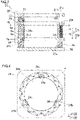
FIG. 3] FIG. 3 is a cross-sectional view (a cross-sectional view taken along line 1000-1000 inFIG. 2 ) illustrating the jig that presses the stacked core and illustrating a finished rotor core mounted to the jig according to the present embodiment. - [
FIG. 4] FIG. 4 is a plan view illustrating the structure of a lower plate of the jig that presses the stacked core according to the present embodiment. - [
FIG. 5] FIG. 5 is a schematic diagram illustrating the structure of a rotor core manufacturing system according to the present embodiment. - [
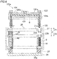
FIG. 6] FIG. 6 is a cross-sectional view used to describe a resin injection portion according to the present embodiment. - [
FIG. 7] FIG. 7 is a flowchart illustrating a rotor core manufacturing method according to the present embodiment. - An embodiment of the present invention is described below with reference to the drawings.
- Referring to
FIGS. 1 to 7 , a manufacturing method for arotor core 4 and amanufacturing system 200 for therotor core 4, according to the present embodiment, are described. - In the present description, an "axial direction" refers to directions along a rotational axis C1 of a rotor 1 (the rotor core 4) and corresponds to a direction Z illustrated in the drawings. In addition, a "radial direction" refers to a radial direction (a direction R1 or a direction R2) of the rotor 1 (the rotor core 4), and a "circumferential direction" refers to a circumferential direction (a direction E1 or a direction E2) of the rotor 1 (the rotor core 4).
- First, referring to
FIG. 1 , the structure of therotor 1 according to the present embodiment is described. - As illustrated in
FIG. 1 , therotor 1 and astator 2 are annularly shaped. Therotor 1 is located radially inside thestator 2 to face thestator 2. That is, according to the present embodiment, the rotatingelectrical machine 100 is structured as an inner-rotor-type rotating electrical machine. Ashaft 3 is located radially inside therotor 1. Theshaft 3 is coupled to, for example, an engine and an axle via a member that transmits a rotational force, such as a gear. For example, the rotatingelectrical machine 100 is structured as a motor, a generator, or a motor-generator and is structured to be mounted on a vehicle. - The
rotor core 4 is provided with astacked core 4d in which a plurality ofelectrical steel sheets 4a (refer toFIG. 3 ) is stacked together and that has amagnet holding portion 10 that is a through hole extending in the stack direction of theelectrical steel sheets 4a. Further, therotor core 4 is provided with apermanent magnet 5 that is inserted in themagnet holding portion 10 of the stackedcore 4d. A plurality of (32 in the present embodiment)magnet holding portions 10 is provided in therotor core 4. That is, the rotatingelectrical machine 100 is structured as an interior permanent magnet motor (IPM motor). Two of themagnet holding portions 10 that are adjacent to each other are arranged in a V-shape. It is noted that the arrangement of themagnet holding portions 10 is not limited to this. - Further, the
stator 2 includes astator core 2a and acoil 2b that is mounted in thestator core 2a. Thestator core 2a is structured, for example, by stacking a plurality of electrical steel sheets (silicon steel sheets) together in the axial direction in such a manner as to allow magnetic flux to pass therethrough. Thecoil 2b is coupled to an external power supply portion and is structured to be supplied with electric power (e.g., three-phase alternating current power). Thecoil 2b is structured to generate a magnetic field by being supplied with electric power. Therotor 1 and theshaft 3 are structured to rotate with respect to thestator 2 together with driving of an engine or the like, even when no electric power is supplied to thecoil 2b. AlthoughFIG. 1 illustrates only part of thecoil 2b, thecoil 2b is mounted over the entire circumference of thestator core 2a. - The
permanent magnet 5 is rectangular in cross section perpendicular to the axial direction of therotor core 4. For example, thepermanent magnet 5 is structured to have a direction of magnetization (a magnetized direction) along the short sides thereof. - Further, as illustrated in
FIG. 3 , therotor core 4 is provided with aresin material 6 that is charged in themagnet holding portions 10. Theresin material 6 is provided to fix thepermanent magnets 5 that are placed in themagnet holding portions 10. - Next, referring to
FIGS. 2 to 4 , the structure of ajig 20 according to the present embodiment is described. It is noted that the description below describes the structure of thejig 20 in a state where the stackedcore 4d is already mounted to thejig 20. - As illustrated in
FIG. 3 , thejig 20 includes anupper plate 21, apressing spring 22, apressing plate 23, alower plate 24, athermal insulator 25, apositioning plate 26, and a clampingmember 27. It is noted that theupper plate 21, thepressing plate 23, thelower plate 24, and thepositioning plate 26 are all made of stainless steel (SUS). - As illustrated in
FIG. 2 , theupper plate 21 has a throughhole 21a in the center thereof and is annularly shaped. Further, theupper plate 21 includes a plurality ofresin injection holes 21b. Theresin injection holes 21b are provided such thatinjection nozzles 122 of aresin injection apparatus 103 that is described later are insertable therein. Specifically, theresin injection holes 21b are provided in such a manner as to individually overlap the plurality of (32 in the present embodiment)magnet holding portions 10. It is noted that theresin injection holes 21b are one example of a "hole portion" recited in the claims. - As illustrated in
FIGS. 2 and3 , thepressing spring 22 is provided in such a manner as to couple theupper plate 21 and thepressing plate 23 together. Specifically, a plurality ofpressing springs 22 is provided at equal angular intervals in the circumferential direction when viewed in the direction of the rotational axis C1. According to the present embodiment, fourpressing springs 22 are provided. Each of the plurality ofpressing springs 22 is provided at a position that overlaps the stackedcore 4d, when viewed from above (from the direction Z1), in a state where the stackedcore 4d is already mounted to thejig 20. - Further, as illustrated in
FIG. 3 , thepressing plate 23 is located on a top surface 4b of the stackedcore 4d. Thepressing plate 23 is provided in such a manner as to press the top surface 4b of the stackedcore 4d by using biasing forces of the pressing springs 22. - Further, the
pressing plate 23 has a throughhole 23a in the center thereof and is annularly shaped. In addition, thepressing plate 23 includes a plurality ofresin injection holes 23b. The plurality ofresin injection holes 23b is provided at positions that overlap the plurality ofresin injection holes 21b in theupper plate 21 when viewed from above (from the direction Z1). It is noted that theresin injection holes 23b are one example of the "hole portion" recited in the claims. - The stacked
core 4d is placed (put) on thelower plate 24. That is, thelower plate 24 is in contact with abottom surface 4c of the stackedcore 4d. Thelower plate 24 has a throughhole 24a in the center thereof and is annularly shaped. Further, thelower plate 24 includes a plurality of (three in the present embodiment) cutportions 24b. The plurality ofcut portions 24b is provided on the inner circumference of the throughhole 24a at almost equal angular intervals (refer toFIG. 4 ) in the circumferential direction when viewed in the direction of the rotational axis C1. - The plurality of
cut portions 24b is provided with L-shapedpositioning portions 24c. The radial and circumferential positions of the stackedcore 4d relative to thelower plate 24 are decided by the plurality ofpositioning portions 24c. Thepositioning portions 24c are fixed (fastened) by fasteningbolts 24d to thelower plate 24. - Further, the
thermal insulator 25 is provided in such a manner as to be held between thelower plate 24 and thepositioning plate 26. Thethermal insulator 25 has a throughhole 25a in the center thereof and is annularly shaped. In addition, thethermal insulator 25 is made of resin. - The
positioning plate 26 is provided below the lower plate 24 (in the direction Z2). - The clamping
member 27 has a U-shape and is provided in such a manner as to clamp theupper plate 21 and thelower plate 24 together. Thus, the stackedcore 4d is held and pressed between theupper plate 21 and thelower plate 24 in a vertical direction (in the direction Z). Specifically, theupper plate 21 holds and presses the stackedcore 4d indirectly via thepressing plate 23 in conjunction with thelower plate 24. As a result, the stackedcore 4d is fixed to thejig 20. A plurality of (four in the present embodiment) clampingmembers 27 is provided. The plurality of clampingmembers 27 is provided at almost equal angular intervals (i.e., at intervals of 90 degrees) in the circumferential direction when viewed in the direction of the rotational axis C1. - Next, referring to
FIG. 5 , amanufacturing system 200 for therotor core 4 is described. - As illustrated in
FIG. 5 , themanufacturing system 200 for therotor core 4 is provided with anassembly apparatus 101, a preheatingheater apparatus 102, theresin injection apparatus 103, and a curingheater apparatus 104. Further, themanufacturing system 200 for therotor core 4 is provided with atransfer conveyor 108 that transfers the stackedcore 4d. It is noted that theassembly apparatus 101, the preheatingheater apparatus 102, theresin injection apparatus 103, and the curingheater apparatus 104 are apparatuses that are separate from each other. - The
assembly apparatus 101 is structured to mount (assemble) the stackedcore 4d to thejig 20. Specifically, theassembly apparatus 101 is structured to mount the stackedcore 4d to thejig 20 and to mount thepermanent magnets 5 in themagnet holding portions 10. - The preheating
heater apparatus 102 is structured to perform preheating by heating the stackedcore 4d. Specifically, the preheatingheater apparatus 102 is structured to perform preheating by heating the stackedcore 4d that remains mounted to thejig 20 at a temperature that is greater than or equal to a first temperature T1 (e.g., 50°C) and less than a second temperature T2 (e.g., 120°C). It is noted that the first temperature T1 is a temperature at which theresin material 6 melts (a temperature at which the melting starts). On the other hand, the second temperature T2 is a temperature at which theresin material 6 cures (thermally cures) (a temperature at which the curing (the thermal curing) starts) and that is greater than the first temperature T1. - The
resin injection apparatus 103 is structured to inject theresin material 6 into themagnet holding portions 10. Specifically, theresin injection apparatus 103 is structured to inject theresin material 6 that has been melted at the first temperature T1 or greater into themagnet holding portions 10, while the stackedcore 4d remains mounted to thejig 20 and thepermanent magnets 5 remain inserted in themagnet holding portions 10. Details of the structure of theresin injection apparatus 103 are described later. - The curing
heater apparatus 104 is structured to cure theresin material 6 in themagnet holding portions 10 by heating the stackedcore 4d. Specifically, the curingheater apparatus 104 is structured to cure theresin material 6 in themagnet holding portions 10 by heating the stackedcore 4d that remains mounted to thejig 20 and that has theresin material 6 injected in themagnet holding portions 10, at a temperature greater than or equal to the second temperature T2 that is a temperature at which theresin material 6 cures. - Next, referring to
FIG. 6 , the specific structure of theresin injection apparatus 103 is described. - As illustrated in
FIG. 6 , theresin injection apparatus 103 includes aresin injection portion 103a. - Here, according to the present embodiment, the
resin material 6 is structured to melt at the first temperature T1 and to cure at the second temperature T2 greater than the first temperature T1. For example, a resin material 6 (synthetic resin material) such as disclosed inJapanese Unexamined Patent Application Publication No. 2000-239642 JP 2000-239642 A resin material 6 includes a reactive hot melt adhesive composition that contains 10% to 100% of a first compound having at least 100 eq/T of uretdione rings, 0% to 90% of a second compound having active hydrogen groups at molecular ends, and 0% to 90% of a third compound having glycidyl groups, and the reactive hot melt adhesive composition is characterized in that none of the first to third compounds have isocyanate groups at molecular ends. Theresin material 6 disclosed inJP 2000-239642 A resin material 6 reaches the first temperature T1. Further, thisresin material 6 does not cure while it is maintained at the first temperature T1. On the other hand, thisresin material 6 cures when it reaches the second temperature T2 greater than the first temperature T1. - As illustrated in
FIG. 6 , aflow channel 121 where theresin material 6 flows is provided within theresin injection portion 103a. Theflow channel 121 branches into a plurality offlow channels 121a toward the stackedcore 4d.Flow channels 121b of theflow channel 121 on the side closer to the stackedcore 4d are provided at positions corresponding to themagnet holding portions 10 of the stackedcore 4d. - Further, the
resin injection portion 103a is provided with theinjection nozzles 122. The injection nozzles 122 are provided on the distal-end side (theflow channels 121b) of theflow channel 121. Theresin material 6 stored in theflow channel 121 is injected into themagnet holding portions 10 of the stackedcore 4d from theinjection nozzles 122 of theresin injection portion 103a. - Additionally, as illustrated in
FIG. 6 , theflow channels 121b are provided withstop valves 123. When theresin material 6 is pushed out of theinjection nozzles 122, thestop valves 123 change to an open state. On the other hand, when theresin material 6 is not pushed out of theinjection nozzles 122, thestop valves 123 change to a closed state. It is noted that thestop valves 123 are one example of an "interrupting portion" recited in the claims. - Further, a
heating device 124 is provided outside theresin injection portion 103a. Theheating device 124 heats theresin injection portion 103a such that the temperature of theresin material 6 stored within theresin injection portion 103a reaches the first temperature T1. - Next, referring to
FIG. 7 , the manufacturing method for therotor core 4 is described. - First, as illustrated in
FIG. 7 , in step S1, a step of preparing the stackedcore 4d is performed. Specifically, the stackedcore 4d is formed by stacking a plurality ofelectrical steel sheets 4a together. At this time, themagnet holding portions 10 that extend in the stack direction of theelectrical steel sheets 4a are formed in the stackedcore 4d by press working. - Then, in step S2, steps of mounting the stacked
core 4d to thejig 20 are performed in theassembly apparatus 101. In these steps, the stackedcore 4d is mounted to thejig 20 such that the stackedcore 4d is held and pressed in the vertical direction (in the direction Z) between the upper plate 21 (the pressing plate 23) and thelower plate 24. Specifically, first, a step of placing (putting) the stackedcore 4d on thelower plate 24 is performed. Next, a step of placing thepermanent magnets 5 in themagnet holding portions 10 are performed while the stackedcore 4d remains on thelower plate 24. Then, thelower plate 24 and theupper plate 21 are clamped (coupled) together by the clampingmember 27 so that the top surface 4b of the stackedcore 4d is pressed by thepressing plate 23. It is noted that the steps of mounting the stackedcore 4d to the jig 20 (the steps in step S2) are steps of mounting the stackedcore 4d to thejig 20 that is provided with thethermal insulator 25. - Next, in step S3, a step of preheating the stacked
core 4d is performed. Specifically, the preheatingheater apparatus 102 performs the preheating step by heating the stackedcore 4d that remains mounted to thejig 20, at the temperature that is greater than or equal to the first temperature T1 and less than the second temperature T2. - Next, in step S4, a step of injecting the
resin material 6 into themagnet holding portions 10 is performed. Specifically, according to the present embodiment, theresin injection portion 103a included in theresin injection apparatus 103 injects theresin material 6 that is in a molten state into themagnet holding portions 10, while the stackedcore 4d remains pressed by thejig 20 and thepermanent magnets 5 remain inserted in themagnet holding portions 10. Specifically, theresin material 6 that is in a molten state is injected while the temperature of theresin material 6 is greater than or equal to the first temperature T1 and less than the second temperature T2. It is noted that in the step of injecting theresin material 6, theresin material 6 that is solid at ordinary temperatures is melted at the first temperature T1, and then themolten resin material 6 is injected into themagnet holding portions 10. - Specifically, as illustrated in
FIG. 6 , theresin injection portion 103a is stationary. The stackedcore 4d that remains pressed by thejig 20 is moved up toward theresin injection portion 103a that remains stationary. Next, theinjection nozzles 122 of theresin injection portion 103a are inserted into themagnet holding portions 10 that have thepermanent magnets 5 therein. Then, thestop valves 123 are changed to the open state so that theresin material 6 is supplied to fill themagnet holding portions 10. After the filling of themagnet holding portions 10 with theresin material 6 is finished, thestop valves 123 are changed to a closed state. - Further, according to the present embodiment, in the step of injecting the
resin material 6, theresin material 6 is injected into themagnet holding portions 10 while pressure is applied to theresin material 6. As themagnet holding portions 10 are filled with theresin material 6, the pressure applied to theresin material 6 increases above a predetermined threshold. After the increased pressure is maintained for a predetermined period of time, the injection of theresin material 6 is stopped. For example, after the pressure applied to theresin material 6 increases above the predetermined threshold (e.g., about 8.5 Mpa), the increased pressure is maintained for about five seconds. It is noted that of all theresin material 6 stored in theresin injection portion 103a, only the necessary amount of theresin material 6 is injected directly into themagnet holding portions 10. Theresin material 6 may be injected into themagnet holding portions 10 while the tips of theinjection nozzles 122 are in abutment with the stackedcore 4d. Alternatively, theresin material 6 may be injected into themagnet holding portions 10 while the tips pf theinjection nozzles 122 are in abutment with the jig 20 (while theinjection nozzles 122 are separated from the stackedcore 4d). - Further, according to the present embodiment, in the step of injecting the
resin material 6, theresin material 6 is injected by theresin injection portion 103a into themagnet holding portions 10 through the resin injection holes 21b and theresin injection holes 23b provided in thejig 20 that presses the stackedcore 4d. Specifically, theinjection nozzles 122 of theresin injection portion 103a are inserted through the resin injection holes 21b and theresin injection holes 23b. Then, theresin material 6 is injected into themagnet holding portions 10 from theinjection nozzles 122 inserted through the resin injection holes 21b and theresin injection holes 23b. That is, according to the present embodiment, in the step of injecting theresin material 6, theresin material 6 is injected into themagnet holding portions 10 from above. - Furthermore, according to the present embodiment, in the step of injecting the
resin material 6, themolten resin material 6 that is in a molten state is injected into themagnet holding portions 10 while the stackedcore 4d remains mounted to thejig 20 that is provided with thethermal insulator 25. Thus, thethermal insulator 25 suppresses the transfer of heat of theresin material 6 to thepositioning plate 26 of thejig 20. - It is noted here that according to the present embodiment, in step S5 (refer to
FIG. 7 ) after the step of injecting theresin material 6 into themagnet holding portions 10, theresin injection portion 103a of theresin injection apparatus 103 is retracted relative to the stackedcore 4d that remains pressed by thejig 20, while theresin material 6 stored in theresin injection portion 103a is maintained in a molten state. That is, theresin injection portion 103a is retracted relative to the stackedcore 4d while the heating is maintained such that the temperature of theresin material 6 stored in theresin injection portion 103a is equal to the first temperature T1. - Further, according to the present embodiment, in the step of relatively retracting the
resin injection portion 103a after theresin material 6 is injected by theresin injection portion 103a into themagnet holding portions 10, theresin injection portion 103a is relatively retracted while thestop valves 123 provided to theresin injection portion 103a interrupt the injection of theresin material 6 from theresin injection portion 103a (i.e., while thestop valves 123 are in a closed state). Furthermore, in the step of relatively retracting theresin injection portion 103a, theresin injection portion 103a is relatively retracted while the pressure applied to theresin material 6 is less than the pressure that is applied to theresin material 6 in the step of injecting theresin material 6. - Further, according to the present embodiment, in the step of relatively retracting the
resin injection portion 103a, theresin injection portion 103a is relatively retracted by moving the stackedcore 4d away from theresin injection portion 103a. In other words, theresin injection portion 103a is moved away relative to the stackedcore 4d, without moving theresin injection portion 103a, by moving down the stackedcore 4d away from theresin injection portion 103a. - Next, as illustrated in
FIG. 7 , in step S6 after the step of relatively retracting theresin injection portion 103a, theresin material 6 in themagnet holding portions 10 is cured by heating the stackedcore 4d that has theresin material 6 injected in themagnet holding portions 10 and that remains pressed by thejig 20. Specifically, theresin material 6 in themagnet holding portions 10 is cured by heating the stackedcore 4d that has theresin material 6 injected in themagnet holding portions 10 and that remains pressed by thejig 20, at a temperature greater than or equal to the second temperature T2 at which theresin material 6 cures. According to the present embodiment, in the step of curing theresin material 6 in themagnet holding portions 10, theresin material 6 in themagnet holding portions 10 is cured by the curingheater apparatus 104 that is provided separately from theresin injection apparatus 103. - The present embodiment provides the following effects.
- As described above, the present embodiment includes: a step of retracting the resin injection portion (103a) of the resin injection apparatus (103) relative to the stacked core (4d) that remains pressed by the jig (20), after the step of injecting the resin material (6) into the magnet holding portion (10), while maintaining the molten state of the resin material (6) that is stored in the resin injection portion (103a), and a step of curing the resin material (6) in the magnet holding portion (10), after the step of relatively retracting the resin injection portion (103a), by heating the stacked core (4d) that has the resin material (6) injected in the magnet holding portion (10) and that remains pressed by the jig (20). Thus, since the resin injection portion (103a) of the resin injection apparatus (103) is already retracted relative to the stacked core (4d) when the resin material (6) is cured, the resin material (6) stored in the resin injection portion (103a) does not cure. As a result, since it is not necessary to remove the resin material (6) cured in the resin injection portion (103a) beforehand, all the resin material (6) stored in the resin injection portion (103a) is capable of being used for fixation (resin sealing) of a permanent magnet (5). This allows an increase in the yield of the resin material (6). In addition, since the step of injecting the molten resin material (6) by the resin injection portion (103a) while the stacked core (4d) remains pressed by the jig (20) is included, the molten resin material (6) is injected while clearances between stacked electrical steel sheets (4a) are closed. Thus, leakage of the resin material (6) from between the stacked electrical steel sheets (4a) can be suppressed. This allows a further increase in the yield of the resin material (6).
- According to the present embodiment, as described above, the step of injecting the resin material (6) is a step of injecting the resin material (6) in the molten state into the magnet holding portion (10) by the resin injection portion (103a) while a temperature of the resin material (6) is greater than or equal to a first temperature (T1) and less than a second temperature (T2) that is greater than the first temperature (T1), and the resin material (6) is configured to melt at the first temperature (T1) and configured to cure at the second temperature (T2). Further, the step of curing the resin material (6) is a step of curing the resin material (6) in the magnet holding portion (10) by heating the stacked core (4d) that has the resin material (6) injected in the magnet holding portion (10) and that remains pressed by the jig (20), at the second temperature (T2) or greater, the second temperature (T2) being a temperature at which the resin material (6) cures. Thus, since the resin material (6) melts at the first temperature (T1) and cures at the second temperature (T2) greater than the first temperature (T1), it is possible to prevent the resin material (6) that has a temperature greater than or equal to the first temperature (T1) and less than the second temperature (T2) from being cured during the step of injecting the resin material (6). In addition, by heating the stacked core (4d) that has the injected resin material (6) at the second temperature (T2) or greater, it is possible to surely cure the molten resin material (6).
- Further, according to the present embodiment, as described above, the step of curing the resin material (6) in the magnet holding portion (10) is a step of curing the resin material (6) in the magnet holding portion (10) by heating the stacked core (4d) at the second temperature (T2) or greater in a curing heater apparatus (104) that is provided separately from the resin injection apparatus (103). According to this structure, since the resin material (6) in the magnet holding portion (10) is cured by the curing heater apparatus (104) that is provided separately from the resin injection apparatus (103), it is possible to surely prevent the resin material (6) stored in the resin injection portion (103a) from being cured. Further, if the resin injection apparatus (103) is used also to cure the resin material (6), the resin injection apparatus (103) is occupied also during the curing of the resin material (6). The above structure permits the resin injection apparatus (103) to be unoccupied during the curing of the resin material (6), thus allowing efficient manufacturing of a rotor (1).
- Further, according to the present embodiment, as described above, the step of injecting the resin material (6) is a step of melting the resin material (6) that is solid at ordinary temperatures at the first temperature (T1), and is a step of injecting the resin material (6) in the molten state into the magnet holding portion (10). This structure enables the resin injection apparatus (103) to continuously perform melting of the solid resin material (6) and injection of the molten resin material (6) into the magnet holding portion (10) without transferring the resin material (6) that is melted in another apparatus to the resin injection apparatus (103), thus allowing a reduction in the time required to manufacture the rotor (1).
- Further, according to the present embodiment, as described above, the step of injecting the resin material (6) is a step of injecting the resin material (6) into the magnet holding portion (10) while applying pressure to the resin material (6) such that the pressure applied to the resin material (6) increases above a predetermined threshold as a result of filling the magnet holding portion (10) with the resin material (6), and is a step of stopping injection of the resin material (6) after maintaining the increased pressure for a predetermined period of time. It is noted here that the resin material (6) may have some bubbles therein. In this case, if the injection of the resin material (6) is stopped at the instance when the pressure applied to the resin material (6) increases above the predetermined threshold, the bubbles remain trapped in the resin material (6) and reduce the strength of the cured resin material (6) (the sealing strength of the permanent magnet (5)). For this reason, as described above, the injection of the resin material (6) is stopped, after the pressure applied to the resin material (6) increases above the predetermined threshold and the increased pressure is maintained for the predetermined period of time. Thus, the amount of bubbles remaining in the resin material (6) can be decreased. This allows an increase in the strength of the cured resin material (6) (the sealing strength of the permanent magnet (5)).
- Further, according to the present embodiment, as described above, the step of injecting the resin material (6) is a step of injecting the resin material (6) into the magnet holding portion (10) by the resin injection portion (103a) through a hole portion (21b, 23b) provided in the jig (20) that presses the stacked core (4d). This structure allows easy injection of the resin material (6) into the magnet holding portion (10) through the hole portion (21b, 23b) provided in the jig (20) while maintaining the stacked core (4d) pressed by the jig (20).
- Further, according to the present embodiment, as described above, the step of mounting the stacked core (4d) to the jig (20) is a step of mounting the stacked core (4d) to the jig (20) that is provided with a thermal insulator (25), and the step of injecting the resin material (6) is a step of injecting the resin material (6) in the molten state into the magnet holding portion (10) while the stacked core (4d) remains mounted to the jig (20) provided with the thermal insulator (25). This structure enables the thermal insulator (25) to prevent the temperature (the first temperature (T1)) of the molten resin material (6) from transferring to the jig (20).
- Further, according to the present embodiment, as described above, the step of relatively retracting the resin injection portion (103a) is a step of relatively retracting the resin injection portion (103a) while interrupting the injection of the resin material (6) from the resin injection portion (103a) by an interrupting portion (123) that is provided to the resin injection portion (103a), after injecting the resin material (6) into the magnet holding portion (10) by the resin injection portion (103a). This structure enables the interrupting portion (123) to prevent leakage of the resin material (6) from the resin injection portion (103a) when the resin injection portion (103a) is relatively retracted. As a result, a further increase in the yield of the resin material (6) is possible.
- Further, according to the present embodiment, as described above, the step of injecting the resin material (6) is a step of injecting the resin material (6) into the magnet holding portion (10) while applying pressure to the resin material (6), and the step of relatively retracting the resin injection portion (103a) is a step of relatively retracting the resin injection portion (103a) while pressure applied to the resin material (6) is less than the pressure that is applied to the resin material (6) in the step of injecting the resin material (6). This structure lowers the pressure applied to the resin material (6) during the relative retraction of the resin injection portion (103a), thus allowing further prevention of the leakage of the resin material (6) from the resin injection portion (103a) during the relative retraction of the resin injection portion (103a). As a result, a still further increase in the yield of the resin material (6) is possible.
- Further, according to the present embodiment, as described above, the step of relatively retracting the resin injection portion (103a) is a step of relatively retracting the resin injection portion (103a) by moving the stacked core (4d) away from the resin injection portion (103a). It is noted here that the temperature of the resin injection portion (103a) (a second portion (120)) is controlled to maintain the resin material (6) in a molten state. Moving the resin injection portion (103a) makes it difficult to control the temperature of the resin injection portion (103a) (may cause temperature fluctuations). For this reason, the above structure does not move the resin injection portion (103a) (a second portion (120)), thus allowing easy control of the temperature of the resin injection portion (103a).
- Further, according to the present embodiment, as described above, the step of injecting the resin material (6) is a step of injecting the resin material (6) into the magnet holding portion (10) from above, and the step of relatively retracting the resin injection portion (103a) is a step of relatively retracting the resin injection portion (103a) by moving down the stacked core (4d) away from the resin injection portion (103a). It is assumed here that the resin material (6) is injected into the magnet holding portion (10) from below. In this case, when the resin injection portion (103a) is retracted from the magnet holding portion (10), the resin material (6) leaks from the magnet holding portion (10) after the injection of the resin material (6). Therefore, a cover is required in order for the resin material (6) not to leak from the magnet holding portion (10). In contrast, when the resin material (6) is injected into the magnet holding portion (10) from above as described above, the resin material (6) does not leak from the magnet holding portion (10) after the injection of the resin material (6). This allows easy relative retraction of the resin injection portion (103a) from the magnet holding portion (10).
- Further, according to the present embodiment, as described above, the step of mounting the stacked core (4d) to the jig (20) is a step of mounting the stacked core (4d) to the jig (20) such that the stacked core (4d) is held and pressed in a vertical direction between an upper plate (21) that is included in the jig (20) and a lower plate (24) that is included in the jig (20). This ensures that the stacked core (4d) is held and pressed between the upper plate (21) and the lower plate (24), thus allowing stable fixation of the stacked core (4d) to the jig (20).
- The embodiment disclosed above is to be considered in all respects as illustrative and not restrictive. The scope of the present invention is defined by the claims, not the description of the above embodiment, and includes all changes (modifications) that fall within the scope of the claims and the equivalents thereof.
- For example, although the above embodiment illustrates by example that the
resin material 6 in themagnet holding portions 10 is cured by the curingheater apparatus 104 that is provided separately from theresin injection apparatus 103, the present invention is not limited to this. For example, theresin material 6 in themagnet holding portions 10 may be cured by heating the stackedcore 4d in the resin injection apparatus 103 (without transfer of the stackedcore 4d from the resin injection apparatus 103). - Further, although the above embodiment illustrates by example that the stacked
core 4d is mounted to thejig 20 in theassembly apparatus 101, the present invention is not limited to this. For example, the stackedcore 4d may be mounted to thejig 20 in the resin injection apparatus 103 (at a location where theresin injection apparatus 103 is installed). - In addition, although the above embodiment illustrates by example that in the step of injecting the
resin material 6, the injection of theresin material 6 is stopped after the pressure applied to theresin material 6 increases above a predetermined threshold and the increased pressure is maintained for about five seconds, the present invention is not limited to this. For example, the period of time for which the increased pressure is maintained may be less than five seconds. For example, it may be greater than or equal to about one second and less than or equal to about two seconds. - Further, although the above embodiment illustrates by example that the
resin material 6 is injected into themagnet holding portions 10 from above, the present invention is not limited to this. For example, theresin material 6 may be injected into themagnet holding portions 10 from below. - Furthermore, although the embodiment illustrates by example that the
resin injection portion 103a is relatively retracted by moving down the stackedcore 4d away from theresin injection portion 103a, the present invention is not limited to this. For example, theresin injection portion 103a may be relatively retracted by moving up theresin injection portion 103a away from the stackedcore 4d. -
- 4: ROTOR CORE
- 4a: ELECTRICAL STEEL SHEET
- 4d: STACKED CORE
- 5: PERMANENT MAGNET
- 6: RESIN MATERIAL
- 10: MAGNET HOLDING PORTION
- 20: JIG
- 21: UPPER PLATE
- 21b, 23b: RESIN INJECTION HOLE (HOLE PORTION)
- 24: LOWER PLATE
- 103: RESIN INJECTION APPARATUS
- 103a: RESIN INJECTION PORTION
- 104: CURING HEATER APPARATUS
- 123: STOP VALVE (INTERRUPTING PORTION)
- 200: MANUFACTURING SYSTEM
- T1: FIRST TEMPERATURE
- T2: SECOND TEMPERATURE
Claims (13)
- A rotor core manufacturing method comprising:a step of preparing a stacked core in which a plurality of electrical steel sheets is stacked together and that has a magnet holding portion extending in a stack direction of the plurality of electrical steel sheets;a step of placing a permanent magnet in the magnet holding portion;a step of mounting the stacked core to a jig that presses the stacked core in the stack direction;a step of injecting a resin material in a molten state into the magnet holding portion by a resin injection portion that is included in a resin injection apparatus, while the stacked core remains pressed by the jig and the permanent magnet remains inserted in the magnet holding portion;a step of retracting the resin injection portion of the resin injection apparatus relative to the stacked core that remains pressed by the jig, after the step of injecting the resin material into the magnet holding portion, while maintaining the molten state of the resin material that is stored in the resin injection portion; anda step of curing the resin material in the magnet holding portion, after the step of relatively retracting the resin injection portion, by heating the stacked core that has the resin material injected in the magnet holding portion and that remains pressed by the jig.
- The rotor core manufacturing method according to claim 1, whereinthe step of injecting the resin material is a step of injecting the resin material in the molten state into the magnet holding portion by the resin injection portion while a temperature of the resin material is greater than or equal to a first temperature and less than a second temperature that is greater than the first temperature, the resin material configured to melt at the first temperature and configured to cure at the second temperature, andthe step of curing the resin material is a step of curing the resin material in the magnet holding portion by heating the stacked core that has the resin material injected in the magnet holding portion and that remains pressed by the jig, at the second temperature (T2) or greater, the second temperature (T2) being a temperature at which the resin material (6) cures.
- The rotor core manufacturing method according to claim 2, wherein the step of curing the resin material in the magnet holding portion is a step of curing the resin material in the magnet holding portion by heating the stacked core at the second temperature or greater in a curing heater apparatus that is provided separately from the resin injection apparatus.
- The rotor core manufacturing method according to claim 2 or 3, wherein the step of injecting the resin material is a step of melting the resin material that is solid at ordinary temperatures at the first temperature, and is a step of injecting the resin material in the molten state into the magnet holding portion.
- The rotor core manufacturing method according to any one of claims 1 to 4, wherein the step of injecting the resin material is a step of injecting the resin material into the magnet holding portion while applying pressure to the resin material such that the pressure applied to the resin material increases above a predetermined threshold as a result of filling the magnet holding portion with the resin material, and is a step of stopping injection of the resin material after maintaining the increased pressure for a predetermined period of time.
- The rotor core manufacturing method according to any one of claims 1 to 5, wherein the step of injecting the resin material is a step of injecting the resin material into the magnet holding portion by the resin injection portion through a hole portion provided in the jig that presses the stacked core.
- The rotor core manufacturing method according to any one of claims 1 to 6, whereinthe step of mounting the stacked core to the jig is a step of mounting the stacked core to the jig that is provided with a thermal insulator, andthe step of injecting the resin material is a step of injecting the resin material in the molten state into the magnet holding portion while the stacked core remains mounted to the jig provided with the thermal insulator.
- The rotor core manufacturing method according to any one of claims 1 to 7, wherein the step of relatively retracting the resin injection portion is a step of relatively retracting the resin injection portion while interrupting injection of the resin material from the resin injection portion by an interrupting portion that is provided to the resin injection portion, after injecting the resin material into the magnet holding portion by the resin injection portion.
- The rotor core manufacturing method according to any one of claims 1 to 8, whereinthe step of injecting the resin material is a step of injecting the resin material into the magnet holding portion while applying pressure to the resin material, andthe step of relatively retracting the resin injection portion is a step of relatively retracting the resin injection portion while pressure applied to the resin material is less than the pressure that is applied to the resin material in the step of injecting the resin material.
- The rotor core manufacturing method according to any one of claims 1 to 9, wherein the step of relatively retracting the resin injection portion is a step of relatively retracting the resin injection portion by moving the stacked core away from the resin injection portion.
- The rotor core manufacturing method according to claim 10, wherein the step of injecting the resin material is a step of injecting the resin material into the magnet holding portion from above, and
the step of relatively retracting the resin injection portion is a step of relatively retracting the resin injection portion by moving down the stacked core away from the resin injection portion. - The rotor core manufacturing method according to any one of claims 1 to 11, wherein the step of mounting the stacked core to the jig is a step of mounting the stacked core to the jig such that the stacked core is held and pressed in a vertical direction between an upper plate that is included in the jig and a lower plate that is included in the jig.
- A system of manufacturing a rotor core that is provided with a stacked core in which a plurality of electrical steel sheets is stacked together, the stacked core having a magnet holding portion extending in a stack direction of the plurality of electrical steel sheets, the system comprising:a jig that presses, in the stack direction, the stacked core that has a permanent magnet in the magnet holding portion; anda resin injection apparatus that injects a resin material in a molten state into the magnet holding portion by a resin injection portion, while the stacked core remains pressed by the jig and the permanent magnet remains in the magnet holding portion, whereinthe system is structured such that the resin injection portion is retracted relative to the stacked core that remains pressed by the jig, while the resin material stored in the resin injection portion is maintained in the molten state, after injection of the resin material into the magnet holding portion, and such that the resin material in the magnet holding portion is cured by heating the stacked core that has the resin material injected in the magnet holding portion and that remains pressed by the jig.
Applications Claiming Priority (2)
| Application Number | Priority Date | Filing Date | Title |
|---|---|---|---|
| JP2019179567 | 2019-09-30 | ||
| PCT/JP2020/035757 WO2021065613A1 (en) | 2019-09-30 | 2020-09-23 | Manufacturing method of rotor core and manufacturing system of rotor core |
Publications (2)
| Publication Number | Publication Date |
|---|---|
| EP4040654A1 true EP4040654A1 (en) | 2022-08-10 |
| EP4040654A4 EP4040654A4 (en) | 2022-11-23 |
Family
ID=75337313
Family Applications (1)
| Application Number | Title | Priority Date | Filing Date |
|---|---|---|---|
| EP20873103.4A Pending EP4040654A4 (en) | 2019-09-30 | 2020-09-23 | ROTOR CORE MANUFACTURING METHOD AND SYSTEM |
Country Status (5)
| Country | Link |
|---|---|
| US (1) | US12132361B2 (en) |
| EP (1) | EP4040654A4 (en) |
| JP (1) | JP7315012B2 (en) |
| CN (1) | CN114342230A (en) |
| WO (1) | WO2021065613A1 (en) |
Families Citing this family (4)
| Publication number | Priority date | Publication date | Assignee | Title |
|---|---|---|---|---|
| EP4138282A1 (en) * | 2021-08-17 | 2023-02-22 | Siemens Aktiengesellschaft | Method for manufacturing a rotor of a permanently excited dynamoelectric machine |
| JP2025085859A (en) | 2022-04-28 | 2025-06-06 | 株式会社アイシン | Wound-field type rotating electric machine |
| JP2025077301A (en) * | 2023-11-06 | 2025-05-19 | トヨタ紡織株式会社 | Armature manufacturing equipment |
| WO2025177383A1 (en) * | 2024-02-19 | 2025-08-28 | Astemo株式会社 | Manufacturing method for rotor of rotary electric machine, manufacturing apparatus, and rotary electric machine |
Family Cites Families (20)
| Publication number | Priority date | Publication date | Assignee | Title |
|---|---|---|---|---|
| JP2000239642A (en) | 1999-02-23 | 2000-09-05 | Toyobo Co Ltd | Reactive hot melt adhesive composition |
| JP2004260881A (en) | 2003-02-24 | 2004-09-16 | Toyota Motor Corp | Stator of three-phase induction motor and three-phase induction motor |
| JP4855125B2 (en) | 2006-04-07 | 2012-01-18 | 株式会社三井ハイテック | Manufacturing method of rotor laminated core |
| JP4611249B2 (en) * | 2006-06-29 | 2011-01-12 | 株式会社三井ハイテック | Resin sealing method for rotor laminated core |
| JP4414417B2 (en) | 2006-08-22 | 2010-02-10 | 株式会社三井ハイテック | Resin sealing method for rotor laminated core |
| JP5373269B2 (en) | 2007-03-01 | 2013-12-18 | 本田技研工業株式会社 | Motor rotor and manufacturing method thereof |
| JP2008245405A (en) | 2007-03-27 | 2008-10-09 | Aisin Seiki Co Ltd | Rotor and method for manufacturing the same |
| JP4848040B2 (en) | 2010-04-08 | 2011-12-28 | 株式会社オートネットワーク技術研究所 | Terminal structure of wire harness |
| JP2012228032A (en) * | 2011-04-18 | 2012-11-15 | Honda Motor Co Ltd | Manufacturing method of rotor |
| JP5357217B2 (en) | 2011-07-04 | 2013-12-04 | 株式会社三井ハイテック | Manufacturing method of rotor laminated core |
| JP5682579B2 (en) * | 2012-02-06 | 2015-03-11 | トヨタ自動車株式会社 | Rotor manufacturing method and manufacturing apparatus |
| JP6040508B2 (en) * | 2012-10-31 | 2016-12-07 | アピックヤマダ株式会社 | Resin molding apparatus and resin molding method for motor core |
| JP6449530B2 (en) * | 2013-01-15 | 2019-01-09 | 株式会社三井ハイテック | Manufacturing method of rotor laminated core |
| JP6059024B2 (en) | 2013-01-18 | 2017-01-11 | 株式会社三井ハイテック | Manufacturing method of rotor |
| JP6180569B2 (en) * | 2014-02-03 | 2017-08-16 | 株式会社三井ハイテック | Permanent magnet resin sealing method |
| JP6235968B2 (en) * | 2014-06-18 | 2017-11-22 | オークマ株式会社 | Assembling method of rotor of electric motor |
| JP6424613B2 (en) | 2014-12-19 | 2018-11-21 | トヨタ紡織株式会社 | Method of manufacturing core of electric rotating machine |
| JP6398703B2 (en) | 2014-12-25 | 2018-10-03 | アイシン・エィ・ダブリュ株式会社 | Resin filling method and resin filling apparatus |
| JP2017093188A (en) * | 2015-11-12 | 2017-05-25 | 株式会社ジェイテクト | Manufacturing method of rotor for rotating electrical machine |
| WO2020075275A1 (en) | 2018-10-11 | 2020-04-16 | 黒田精工株式会社 | Rotor core holding jig, and device and method for producing magnet-embedded core |
-
2020
- 2020-09-23 US US17/625,038 patent/US12132361B2/en active Active
- 2020-09-23 CN CN202080058696.7A patent/CN114342230A/en active Pending
- 2020-09-23 EP EP20873103.4A patent/EP4040654A4/en active Pending
- 2020-09-23 WO PCT/JP2020/035757 patent/WO2021065613A1/en not_active Ceased
- 2020-09-23 JP JP2021550652A patent/JP7315012B2/en active Active
Also Published As
| Publication number | Publication date |
|---|---|
| JPWO2021065613A1 (en) | 2021-04-08 |
| EP4040654A4 (en) | 2022-11-23 |
| WO2021065613A1 (en) | 2021-04-08 |
| JP7315012B2 (en) | 2023-07-26 |
| US12132361B2 (en) | 2024-10-29 |
| CN114342230A (en) | 2022-04-12 |
| US20220294322A1 (en) | 2022-09-15 |
Similar Documents
| Publication | Publication Date | Title |
|---|---|---|
| US12132361B2 (en) | Rotor core manufacturing method and rotor core manufacturing system | |
| JP7363310B2 (en) | Rotor core pressing jig and rotor core manufacturing method | |
| EP4178093A1 (en) | Rotor core manufacturing method | |
| US12368355B2 (en) | Rotor core manufacturing method and rotor core manufacturing system | |
| CN106165269B (en) | The manufacturing method and its manufacturing equipment of built-in permanent magnet type internal rotor | |
| JP7410778B2 (en) | Resin injection device and rotor core manufacturing method | |
| JP7487581B2 (en) | Manufacturing method of rotor core | |
| JP7338433B2 (en) | Manufacturing method of rotor core | |
| CN105720756A (en) | Method for manufacturing core of rotating electric machine | |
| JP7395995B2 (en) | Rotor core manufacturing method and resin injection device | |
| US20240413721A1 (en) | Method for producing an electric machine | |
| EP3490106A1 (en) | Method of manufacturing core product | |
| JP7342581B2 (en) | Rotor core manufacturing method and rotor core manufacturing device | |
| US12362610B2 (en) | Rotor core and method for manufacturing rotor core | |
| KR20200133479A (en) | Method For Manufacturing Rotor And Magnet Fixing System For Manufacturing Rotor | |
| JP7823554B2 (en) | Manufacturing method for rotor for rotating electric machine | |
| JP7395916B2 (en) | Rotor core manufacturing method and rotor core manufacturing device | |
| EP4092877A1 (en) | Rotor core and method for manufacturing rotor core | |
| US20230179044A1 (en) | Rotor for permanent magnet electrical machine | |
| KR20250163683A (en) | Stator slot molding device and method | |
| JP2024024956A (en) | Rotor manufacturing equipment for rotating electric machines and rotor manufacturing equipment for rotating electric machines | |
| WO2024029254A1 (en) | Manufacturing method for rotating electrical machine-use rotor and manufacturing device for rotating electrical machine-use rotor |
Legal Events
| Date | Code | Title | Description |
|---|---|---|---|
| STAA | Information on the status of an ep patent application or granted ep patent |
Free format text: STATUS: THE INTERNATIONAL PUBLICATION HAS BEEN MADE |
|
| PUAI | Public reference made under article 153(3) epc to a published international application that has entered the european phase |
Free format text: ORIGINAL CODE: 0009012 |
|
| STAA | Information on the status of an ep patent application or granted ep patent |
Free format text: STATUS: REQUEST FOR EXAMINATION WAS MADE |
|
| 17P | Request for examination filed |
Effective date: 20220105 |
|
| AK | Designated contracting states |
Kind code of ref document: A1 Designated state(s): AL AT BE BG CH CY CZ DE DK EE ES FI FR GB GR HR HU IE IS IT LI LT LU LV MC MK MT NL NO PL PT RO RS SE SI SK SM TR |
|
| A4 | Supplementary search report drawn up and despatched |
Effective date: 20221021 |
|
| RIC1 | Information provided on ipc code assigned before grant |
Ipc: H02K 15/12 20060101ALI20221017BHEP Ipc: H02K 1/27 20220101ALI20221017BHEP Ipc: H02K 15/03 20060101AFI20221017BHEP |
|
| DAV | Request for validation of the european patent (deleted) | ||
| DAX | Request for extension of the european patent (deleted) | ||
| STAA | Information on the status of an ep patent application or granted ep patent |
Free format text: STATUS: EXAMINATION IS IN PROGRESS |
|
| 17Q | First examination report despatched |
Effective date: 20260225 |
|
| STAA | Information on the status of an ep patent application or granted ep patent |
Free format text: STATUS: THE APPLICATION HAS BEEN WITHDRAWN |