EP4040603A1 - Connection structure of press-clamping terminal and cable - Google Patents
Connection structure of press-clamping terminal and cable Download PDFInfo
- Publication number
- EP4040603A1 EP4040603A1 EP22153179.1A EP22153179A EP4040603A1 EP 4040603 A1 EP4040603 A1 EP 4040603A1 EP 22153179 A EP22153179 A EP 22153179A EP 4040603 A1 EP4040603 A1 EP 4040603A1
- Authority
- EP
- European Patent Office
- Prior art keywords
- press
- core wire
- cable
- clamping
- clamping terminal
- Prior art date
- Legal status (The legal status is an assumption and is not a legal conclusion. Google has not performed a legal analysis and makes no representation as to the accuracy of the status listed.)
- Granted
Links
Images


Classifications
-
- H—ELECTRICITY
- H01—ELECTRIC ELEMENTS
- H01R—ELECTRICALLY-CONDUCTIVE CONNECTIONS; STRUCTURAL ASSOCIATIONS OF A PLURALITY OF MUTUALLY-INSULATED ELECTRICAL CONNECTING ELEMENTS; COUPLING DEVICES; CURRENT COLLECTORS
- H01R4/00—Electrically-conductive connections between two or more conductive members in direct contact, i.e. touching one another; Means for effecting or maintaining such contact; Electrically-conductive connections having two or more spaced connecting locations for conductors and using contact members penetrating insulation
- H01R4/10—Electrically-conductive connections between two or more conductive members in direct contact, i.e. touching one another; Means for effecting or maintaining such contact; Electrically-conductive connections having two or more spaced connecting locations for conductors and using contact members penetrating insulation effected solely by twisting, wrapping, bending, crimping, or other permanent deformation
- H01R4/18—Electrically-conductive connections between two or more conductive members in direct contact, i.e. touching one another; Means for effecting or maintaining such contact; Electrically-conductive connections having two or more spaced connecting locations for conductors and using contact members penetrating insulation effected solely by twisting, wrapping, bending, crimping, or other permanent deformation by crimping
- H01R4/183—Electrically-conductive connections between two or more conductive members in direct contact, i.e. touching one another; Means for effecting or maintaining such contact; Electrically-conductive connections having two or more spaced connecting locations for conductors and using contact members penetrating insulation effected solely by twisting, wrapping, bending, crimping, or other permanent deformation by crimping for cylindrical elongated bodies, e.g. cables having circular cross-section
- H01R4/184—Electrically-conductive connections between two or more conductive members in direct contact, i.e. touching one another; Means for effecting or maintaining such contact; Electrically-conductive connections having two or more spaced connecting locations for conductors and using contact members penetrating insulation effected solely by twisting, wrapping, bending, crimping, or other permanent deformation by crimping for cylindrical elongated bodies, e.g. cables having circular cross-section comprising a U-shaped wire-receiving portion
- H01R4/185—Electrically-conductive connections between two or more conductive members in direct contact, i.e. touching one another; Means for effecting or maintaining such contact; Electrically-conductive connections having two or more spaced connecting locations for conductors and using contact members penetrating insulation effected solely by twisting, wrapping, bending, crimping, or other permanent deformation by crimping for cylindrical elongated bodies, e.g. cables having circular cross-section comprising a U-shaped wire-receiving portion combined with a U-shaped insulation-receiving portion
-
- H—ELECTRICITY
- H01—ELECTRIC ELEMENTS
- H01R—ELECTRICALLY-CONDUCTIVE CONNECTIONS; STRUCTURAL ASSOCIATIONS OF A PLURALITY OF MUTUALLY-INSULATED ELECTRICAL CONNECTING ELEMENTS; COUPLING DEVICES; CURRENT COLLECTORS
- H01R4/00—Electrically-conductive connections between two or more conductive members in direct contact, i.e. touching one another; Means for effecting or maintaining such contact; Electrically-conductive connections having two or more spaced connecting locations for conductors and using contact members penetrating insulation
- H01R4/10—Electrically-conductive connections between two or more conductive members in direct contact, i.e. touching one another; Means for effecting or maintaining such contact; Electrically-conductive connections having two or more spaced connecting locations for conductors and using contact members penetrating insulation effected solely by twisting, wrapping, bending, crimping, or other permanent deformation
- H01R4/18—Electrically-conductive connections between two or more conductive members in direct contact, i.e. touching one another; Means for effecting or maintaining such contact; Electrically-conductive connections having two or more spaced connecting locations for conductors and using contact members penetrating insulation effected solely by twisting, wrapping, bending, crimping, or other permanent deformation by crimping
- H01R4/183—Electrically-conductive connections between two or more conductive members in direct contact, i.e. touching one another; Means for effecting or maintaining such contact; Electrically-conductive connections having two or more spaced connecting locations for conductors and using contact members penetrating insulation effected solely by twisting, wrapping, bending, crimping, or other permanent deformation by crimping for cylindrical elongated bodies, e.g. cables having circular cross-section
- H01R4/184—Electrically-conductive connections between two or more conductive members in direct contact, i.e. touching one another; Means for effecting or maintaining such contact; Electrically-conductive connections having two or more spaced connecting locations for conductors and using contact members penetrating insulation effected solely by twisting, wrapping, bending, crimping, or other permanent deformation by crimping for cylindrical elongated bodies, e.g. cables having circular cross-section comprising a U-shaped wire-receiving portion
-
- H—ELECTRICITY
- H01—ELECTRIC ELEMENTS
- H01R—ELECTRICALLY-CONDUCTIVE CONNECTIONS; STRUCTURAL ASSOCIATIONS OF A PLURALITY OF MUTUALLY-INSULATED ELECTRICAL CONNECTING ELEMENTS; COUPLING DEVICES; CURRENT COLLECTORS
- H01R4/00—Electrically-conductive connections between two or more conductive members in direct contact, i.e. touching one another; Means for effecting or maintaining such contact; Electrically-conductive connections having two or more spaced connecting locations for conductors and using contact members penetrating insulation
- H01R4/10—Electrically-conductive connections between two or more conductive members in direct contact, i.e. touching one another; Means for effecting or maintaining such contact; Electrically-conductive connections having two or more spaced connecting locations for conductors and using contact members penetrating insulation effected solely by twisting, wrapping, bending, crimping, or other permanent deformation
- H01R4/18—Electrically-conductive connections between two or more conductive members in direct contact, i.e. touching one another; Means for effecting or maintaining such contact; Electrically-conductive connections having two or more spaced connecting locations for conductors and using contact members penetrating insulation effected solely by twisting, wrapping, bending, crimping, or other permanent deformation by crimping
-
- H—ELECTRICITY
- H01—ELECTRIC ELEMENTS
- H01B—CABLES; CONDUCTORS; INSULATORS; SELECTION OF MATERIALS FOR THEIR CONDUCTIVE, INSULATING OR DIELECTRIC PROPERTIES
- H01B7/00—Insulated conductors or cables characterised by their form
- H01B7/17—Protection against damage caused by external factors, e.g. sheaths or armouring
- H01B7/18—Protection against damage caused by wear, mechanical force or pressure; Sheaths; Armouring
-
- H—ELECTRICITY
- H01—ELECTRIC ELEMENTS
- H01R—ELECTRICALLY-CONDUCTIVE CONNECTIONS; STRUCTURAL ASSOCIATIONS OF A PLURALITY OF MUTUALLY-INSULATED ELECTRICAL CONNECTING ELEMENTS; COUPLING DEVICES; CURRENT COLLECTORS
- H01R13/00—Details of coupling devices of the kinds covered by groups H01R12/70 or H01R24/00 - H01R33/00
- H01R13/46—Bases; Cases
- H01R13/52—Dustproof, splashproof, drip-proof, waterproof, or flameproof cases
- H01R13/5202—Sealing means between parts of housing or between housing part and a wall, e.g. sealing rings
-
- H—ELECTRICITY
- H01—ELECTRIC ELEMENTS
- H01R—ELECTRICALLY-CONDUCTIVE CONNECTIONS; STRUCTURAL ASSOCIATIONS OF A PLURALITY OF MUTUALLY-INSULATED ELECTRICAL CONNECTING ELEMENTS; COUPLING DEVICES; CURRENT COLLECTORS
- H01R43/00—Apparatus or processes specially adapted for manufacturing, assembling, maintaining, or repairing of line connectors or current collectors or for joining electric conductors
- H01R43/28—Apparatus or processes specially adapted for manufacturing, assembling, maintaining, or repairing of line connectors or current collectors or for joining electric conductors for wire processing before connecting to contact members, not provided for in groups H01R43/02 - H01R43/26
-
- H—ELECTRICITY
- H01—ELECTRIC ELEMENTS
- H01R—ELECTRICALLY-CONDUCTIVE CONNECTIONS; STRUCTURAL ASSOCIATIONS OF A PLURALITY OF MUTUALLY-INSULATED ELECTRICAL CONNECTING ELEMENTS; COUPLING DEVICES; CURRENT COLLECTORS
- H01R13/00—Details of coupling devices of the kinds covered by groups H01R12/70 or H01R24/00 - H01R33/00
- H01R13/02—Contact members
- H01R13/04—Pins or blades for co-operation with sockets
Definitions
- the present invention relates to a connection structure of a press-clamping terminal and a cable, in which a core wire of a cable is crimped and connected with crimp pieces of a press-clamping terminal.
- JP 2009-295352 A discloses a press-clamping terminal having a pair of core wire barrels that are crimped and press-clamped to a core wire that is made of a plurality of element wires and is exposed from an insulation sheath at a terminal of a cable.
- the pair of core wire barrels of the press-clamping terminal are formed to be inclined such that the amount of projection increases from a front end on the electric contact portion side toward a rear end. Therefore, the compression load of the core wire barrels applied to a core wire can be reduced more on the rear end side than the front end on the electric contact portion side of the core wire barrels.
- the core wire barrels are shaped such that the compression load applied to a core wire by the core wire barrels is more reduced on the rear end side than the front end on the electric contact portion side. Therefore, the structure from the core wire barrels to the end of the cable is increased in size.
- An object of the present invention is to provide a connection structure of a press-clamping terminal and a cable that can, when a core wire of a cable and a press-clamping terminal are press-clamped and connected, suppress deformation of the end of the cable and reduce the size of the area around the press-clamping.
- a connection structure of a press-clamping terminal and a cable includes a cable that includes a core wire and an insulation sheath that covers the core wire, a press-clamping terminal that is press-clamped to the core wire exposed from the insulation sheath at a terminal of the cable, and a cut portion that is formed in a press-clamping direction in the exposed core wire.
- the cut portion of the exposed core wire may be formed by cutting one side in the press-clamping direction.
- the cut portion of the exposed core wire may be formed to include a cross section formed in a semicircular shape.
- a crimp piece of the press-clamping terminal may be crimped and press-clamped to the cut portion of the exposed core wire.
- connection structure of a press-clamping terminal and a cable that can, when a core wire of a cable and a press-clamping terminal are press-clamped and connected, suppress deformation of the end of the cable and reduce the size of the area around the press-clamping.
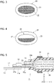
- a connection structure 1 of a press-clamping terminal 10 and a cable 20 includes: the cable 20, which has a core wire 22 and an insulation sheath 21 that covers the core wire 22; the core wire 22, which is exposed from the insulation sheath 21 at an end 20a of the cable 20; and the press-clamping terminal 10, which is press-clamped to the exposed core wire 22.
- reference character X denotes the press-clamping direction (vertical direction)
- reference character Y denotes the axial direction (horizontal direction) of the core wire 22
- reference character Z denotes the longitudinal direction (width direction).
- the press-clamping terminal 10 is formed by press processing a conductive metal plate such as copper or a copper alloy.
- the press-clamping terminal 10 includes a rectangular plate-shaped electrical connection portion 11, and a pair of crimp pieces 12 and 12 that stand upward in the press-clamping direction from both sides of a proximal end 11a of the electrical connection portion 11 in the longitudinal direction.
- the pair of crimp pieces 12 and 12 of the press-clamping terminal 10 are crimped to a cut portion 23 side of the core wire 22 exposed from the insulation sheath 21 at the end 20a of the cable 20, through an anvil and a crimper which are not shown. Accordingly, the pair of crimp pieces 12 and 12 press-clamp and connect the core wire 22.
- the end 20a of the cable 20 is formed by peeling off the insulation sheath 21 at a terminal of the cable 20, and the core wire 22 is exposed.
- the core wire 22 is a conductor composed of a plurality of element wires 22a, and is formed of a conductive material such as copper or a copper alloy, or aluminum or an aluminum alloy.
- the core wire 22 exposed from the insulation sheath 21 of the cable 20 has the cut portion 23 in the press-clamping direction.
- the cut portion 23 has a cross section which is formed in a semicircular shape by cutting one side in the press-clamping direction (the one side is the side opposite to the side facing the press-clamping terminal 10 when the core wire 22 is press-clamped and connected to the press-clamping terminal 10, and is the upper side in the press-clamping direction in FIG. 5 ).
- the press-clamping terminal 10 and the core wire 22 of the cable 20 are press-clamped by means of crimping performed by the pair of crimp pieces 12 and 12 of the press-clamping terminal 10.
- An annular waterproof plug 30 made of rubber is fitted into a position on the end 20a side of the cable 20 press-clamped and connected to the press-clamping terminal 10.
- the cut portion 23 is formed by cutting one side, in the press-clamping direction, of the core wire 22 exposed from the insulation sheath 21 of the cable 20.
- the diameter (thickness) of the core wire 22 in the press-clamping direction is reduced in size, and in this state the core wire 22 is press-clamped by the crimp pieces 12 of the press-clamping terminal 10.
- the flattening of the end 20a of the cable 20 can be suppressed when the core wire 22 exposed from the end 20a of the cable 20 and the press-clamping terminal 10 are press-clamped and connected. Therefore, the area around the press-clamping between the end 20a of the cable 20 including the waterproof plug 30 and the press-clamping terminal 10 can be made smaller.
- the cut portion 23 of the core wire 22 is formed to have a cross section formed in a semicircular shape. Accordingly, when the crimp pieces 12 of the press-clamping terminal 10 and the core wire 22 of the cable 20 are crimped, crimping and connecting can be performed easily.
- a core wire exposed from an insulation sheath of a cable is cut into a semicircular shape to form a cut portion.
- a waterproof plug is fitted into a position on an end side of a cable as a rubber component.
- the rubber component is not limited to being a waterproof plug and may be a protective component, a holding component, or the like.
Landscapes
- Engineering & Computer Science (AREA)
- Manufacturing & Machinery (AREA)
- Connections Effected By Soldering, Adhesion, Or Permanent Deformation (AREA)
Abstract
Description
- The present invention relates to a connection structure of a press-clamping terminal and a cable, in which a core wire of a cable is crimped and connected with crimp pieces of a press-clamping terminal.
-
JP 2009-295352 A - The pair of core wire barrels of the press-clamping terminal are formed to be inclined such that the amount of projection increases from a front end on the electric contact portion side toward a rear end. Therefore, the compression load of the core wire barrels applied to a core wire can be reduced more on the rear end side than the front end on the electric contact portion side of the core wire barrels.
- However, in a connection structure of the press-clamping terminal and a cable, the core wire barrels are shaped such that the compression load applied to a core wire by the core wire barrels is more reduced on the rear end side than the front end on the electric contact portion side. Therefore, the structure from the core wire barrels to the end of the cable is increased in size.
- An object of the present invention is to provide a connection structure of a press-clamping terminal and a cable that can, when a core wire of a cable and a press-clamping terminal are press-clamped and connected, suppress deformation of the end of the cable and reduce the size of the area around the press-clamping.
- A connection structure of a press-clamping terminal and a cable according to an embodiment includes a cable that includes a core wire and an insulation sheath that covers the core wire, a press-clamping terminal that is press-clamped to the core wire exposed from the insulation sheath at a terminal of the cable, and a cut portion that is formed in a press-clamping direction in the exposed core wire.
- The cut portion of the exposed core wire may be formed by cutting one side in the press-clamping direction.
- The cut portion of the exposed core wire may be formed to include a cross section formed in a semicircular shape.
- A crimp piece of the press-clamping terminal may be crimped and press-clamped to the cut portion of the exposed core wire.
- According to the above configuration, it is possible to provide a connection structure of a press-clamping terminal and a cable that can, when a core wire of a cable and a press-clamping terminal are press-clamped and connected, suppress deformation of the end of the cable and reduce the size of the area around the press-clamping.
-
-
FIG. 1 is a perspective view showing an example of a connection structure of a press-clamping terminal and a cable according to an embodiment; -
FIG. 2 is a plan view of a connection structure of a press-clamping terminal and a cable; -
FIG. 3 is a cross-sectional view taken along line III-III inFIG. 2 ; -
FIG. 4 is a cross-sectional view taken along line IV-IV inFIG. 2 ; and -
FIG. 5 is a cross-sectional view taken along line V-V inFIG. 2 . - Hereinafter, a connection structure of a press-clamping terminal and a cable according to an embodiment of the present invention will be described in detail with reference to the drawings.
- As shown in
FIGS. 1 ,2 , and5 , aconnection structure 1 of a press-clamping terminal 10 and acable 20 includes: thecable 20, which has acore wire 22 and aninsulation sheath 21 that covers thecore wire 22; thecore wire 22, which is exposed from theinsulation sheath 21 at anend 20a of thecable 20; and the press-clamping terminal 10, which is press-clamped to the exposedcore wire 22. InFIG. 5 , reference character X denotes the press-clamping direction (vertical direction), reference character Y denotes the axial direction (horizontal direction) of thecore wire 22, and reference character Z denotes the longitudinal direction (width direction). - As shown in
FIGS. 1 and5 , the press-clamping terminal 10 is formed by press processing a conductive metal plate such as copper or a copper alloy. The press-clamping terminal 10 includes a rectangular plate-shapedelectrical connection portion 11, and a pair ofcrimp pieces proximal end 11a of theelectrical connection portion 11 in the longitudinal direction. The pair ofcrimp pieces clamping terminal 10 are crimped to acut portion 23 side of thecore wire 22 exposed from theinsulation sheath 21 at theend 20a of thecable 20, through an anvil and a crimper which are not shown. Accordingly, the pair ofcrimp pieces core wire 22. - As shown in
FIGS. 1 ,2 and5 , theend 20a of thecable 20 is formed by peeling off theinsulation sheath 21 at a terminal of thecable 20, and thecore wire 22 is exposed. Thecore wire 22 is a conductor composed of a plurality ofelement wires 22a, and is formed of a conductive material such as copper or a copper alloy, or aluminum or an aluminum alloy. - The
core wire 22 exposed from theinsulation sheath 21 of thecable 20 has thecut portion 23 in the press-clamping direction. Thecut portion 23 has a cross section which is formed in a semicircular shape by cutting one side in the press-clamping direction (the one side is the side opposite to the side facing the press-clamping terminal 10 when thecore wire 22 is press-clamped and connected to the press-clamping terminal 10, and is the upper side in the press-clamping direction inFIG. 5 ). By forming thecut portion 23 in thecore wire 22 of thecable 20, the height (the thickness) of thecore wire 22 in the press-clamping direction is reduced. As shown inFIGS. 1 ,2 , and5 , the press-clamping terminal 10 and thecore wire 22 of thecable 20 are press-clamped by means of crimping performed by the pair ofcrimp pieces clamping terminal 10. An annularwaterproof plug 30 made of rubber is fitted into a position on theend 20a side of thecable 20 press-clamped and connected to the press-clamping terminal 10. - As described above, according to the
connection structure 1 of the press-clamping terminal 10 and thecable 20 of an embodiment, thecut portion 23 is formed by cutting one side, in the press-clamping direction, of thecore wire 22 exposed from theinsulation sheath 21 of thecable 20. The diameter (thickness) of thecore wire 22 in the press-clamping direction is reduced in size, and in this state thecore wire 22 is press-clamped by thecrimp pieces 12 of the press-clamping terminal 10. By press-clamping and connecting only some of theelement wires 22a constituting thecore wire 22 to the press-clamping terminal 10, flattening (deformation) of theend 20a of thecable 22 can be suppressed when the exposedcore wire 20 of thecable 20 is press-clamped and connected to the press-clamping terminal 10, and thewaterproof plug 30 can be fitted more into a position on theend 20a side of thecable 20. - As described above, the flattening of the
end 20a of thecable 20 can be suppressed when thecore wire 22 exposed from theend 20a of thecable 20 and the press-clamping terminal 10 are press-clamped and connected. Therefore, the area around the press-clamping between theend 20a of thecable 20 including thewaterproof plug 30 and the press-clamping terminal 10 can be made smaller. - Further, by cutting one side in the press-clamping direction, the
cut portion 23 of thecore wire 22 is formed to have a cross section formed in a semicircular shape. Accordingly, when thecrimp pieces 12 of the press-clamping terminal 10 and thecore wire 22 of thecable 20 are crimped, crimping and connecting can be performed easily. - Although the present embodiment has been described above, the present embodiment is not limited to the above description, and various modifications can be made within the scope of the gist of the present embodiment.
- That is, according to the above embodiment, a core wire exposed from an insulation sheath of a cable is cut into a semicircular shape to form a cut portion. However, it is also possible to form a cut portion having a diameter smaller than that of the core wire by cutting a plurality of element wires located at the outer circumference among a plurality of element wires constituting the core wire.
- Further, according to the embodiment, a waterproof plug is fitted into a position on an end side of a cable as a rubber component. However, the rubber component is not limited to being a waterproof plug and may be a protective component, a holding component, or the like.
- Although the present invention has been described above by reference to the embodiment, the present invention is not limited to those and the configuration of parts can be replaced with any configuration having a similar function, as long as they lie within the scope of the claims.
Claims (4)
- A connection structure (1) of a press-clamping terminal and a cable comprising:a cable (20) that includes a core wire (22) and an insulation sheath (21) that covers the core wire (22);a press-clamping terminal (10) that is press-clamped to the core wire (22) exposed from the insulation sheath (21) at a terminal of the cable (20); anda cut portion (23) that is formed in a press-clamping direction in the exposed core wire (22).
- The connection structure (1) of the press-clamping terminal and the cable according to claim 1, wherein
the cut portion (23) of the exposed core wire (22) is formed by one side in the press-clamping direction being cut. - The connection structure (1) of the press-clamping terminal and the cable according to claim 2, wherein
the cut portion (23) of the exposed core wire (22) is formed to include a cross section formed in a semicircular shape. - The connection structure (1) of the press-clamping terminal and the cable according to claim 2 or 3, wherein
a crimp piece (12) of the press-clamping terminal (10) is crimped and press-clamped on a cut portion side of the exposed core wire (22).
Applications Claiming Priority (1)
| Application Number | Priority Date | Filing Date | Title |
|---|---|---|---|
| JP2021015544A JP2022118805A (en) | 2021-02-03 | 2021-02-03 | Connection structure of crimp terminal and electric wire |
Publications (2)
| Publication Number | Publication Date |
|---|---|
| EP4040603A1 true EP4040603A1 (en) | 2022-08-10 |
| EP4040603B1 EP4040603B1 (en) | 2023-09-13 |
Family
ID=80035073
Family Applications (1)
| Application Number | Title | Priority Date | Filing Date |
|---|---|---|---|
| EP22153179.1A Active EP4040603B1 (en) | 2021-02-03 | 2022-01-25 | Connection structure of press-clamping terminal and cable |
Country Status (4)
| Country | Link |
|---|---|
| US (1) | US11764492B2 (en) |
| EP (1) | EP4040603B1 (en) |
| JP (1) | JP2022118805A (en) |
| CN (1) | CN114865339A (en) |
Families Citing this family (1)
| Publication number | Priority date | Publication date | Assignee | Title |
|---|---|---|---|---|
| JP7111784B2 (en) * | 2020-09-11 | 2022-08-02 | 矢崎総業株式会社 | Female contact manufacturing method |
Citations (5)
| Publication number | Priority date | Publication date | Assignee | Title |
|---|---|---|---|---|
| JP2009295352A (en) | 2008-06-03 | 2009-12-17 | Sumitomo Wiring Syst Ltd | Crimp terminal |
| DE102013204720A1 (en) * | 2012-03-16 | 2013-09-19 | Yazaki Corporation | Wire with crimp connection |
| US20140311797A1 (en) * | 2013-04-17 | 2014-10-23 | Yazaki Corporation | Electric wire connection structure and electric wire connection method |
| WO2017115710A1 (en) * | 2015-12-28 | 2017-07-06 | 住友電装株式会社 | Method for producing cable with terminal, and cable with terminal |
| EP3579341A1 (en) * | 2018-06-04 | 2019-12-11 | Yazaki Corporation | Electric wire with terminal and method of manufacturing electric wire with terminal |
Family Cites Families (4)
| Publication number | Priority date | Publication date | Assignee | Title |
|---|---|---|---|---|
| JP2010225529A (en) * | 2009-03-25 | 2010-10-07 | Autonetworks Technologies Ltd | Electric wire with terminal metal fitting |
| AT516375B1 (en) * | 2014-12-04 | 2016-05-15 | Gebauer & Griller | Cable contact system and method for electrically connecting a cable to a contact piece |
| JP6912295B2 (en) * | 2017-07-07 | 2021-08-04 | 矢崎総業株式会社 | Wire with terminal |
| JP6768742B2 (en) * | 2018-06-04 | 2020-10-14 | 矢崎総業株式会社 | Manufacturing method of electric wire with terminal and electric wire with terminal |
-
2021
- 2021-02-03 JP JP2021015544A patent/JP2022118805A/en active Pending
-
2022
- 2022-01-25 EP EP22153179.1A patent/EP4040603B1/en active Active
- 2022-01-26 CN CN202210094242.6A patent/CN114865339A/en active Pending
- 2022-02-02 US US17/591,187 patent/US11764492B2/en active Active
Patent Citations (5)
| Publication number | Priority date | Publication date | Assignee | Title |
|---|---|---|---|---|
| JP2009295352A (en) | 2008-06-03 | 2009-12-17 | Sumitomo Wiring Syst Ltd | Crimp terminal |
| DE102013204720A1 (en) * | 2012-03-16 | 2013-09-19 | Yazaki Corporation | Wire with crimp connection |
| US20140311797A1 (en) * | 2013-04-17 | 2014-10-23 | Yazaki Corporation | Electric wire connection structure and electric wire connection method |
| WO2017115710A1 (en) * | 2015-12-28 | 2017-07-06 | 住友電装株式会社 | Method for producing cable with terminal, and cable with terminal |
| EP3579341A1 (en) * | 2018-06-04 | 2019-12-11 | Yazaki Corporation | Electric wire with terminal and method of manufacturing electric wire with terminal |
Also Published As
| Publication number | Publication date |
|---|---|
| US20220247094A1 (en) | 2022-08-04 |
| EP4040603B1 (en) | 2023-09-13 |
| US11764492B2 (en) | 2023-09-19 |
| CN114865339A (en) | 2022-08-05 |
| JP2022118805A (en) | 2022-08-16 |
Similar Documents
| Publication | Publication Date | Title |
|---|---|---|
| US8876564B2 (en) | Connection structure of crimping terminal to electric wire | |
| JP5884986B2 (en) | Aluminum wire with crimp terminal | |
| JP5282462B2 (en) | Electric wire with terminal | |
| US10811788B2 (en) | Electric wire with terminal | |
| US9608339B2 (en) | Crimped terminal attached aluminum electric wire | |
| US20110117769A1 (en) | Insulation displacement terminal, splicing terminal assembly and press-contact structure for electric cable | |
| JP2010073320A (en) | Crimping structure of crimp terminal | |
| US20180138600A1 (en) | Terminal and terminal-equipped electric wire | |
| US11764492B2 (en) | Connection structure of press-clamping terminal and cable | |
| US5120259A (en) | Electrical connector | |
| JP5798840B2 (en) | Connecting terminal | |
| US5885104A (en) | Electrical plug connector | |
| US11417979B2 (en) | Shielded electrical connector assembly and method of manufacturing same | |
| JPH0572053U (en) | Wire crimp terminal | |
| EP3989363A1 (en) | Electrical crimp terminal | |
| CN107431282B (en) | Terminals and Wires with Terminals | |
| CN110323582A (en) | Electric wire with terminal | |
| EP3787119B1 (en) | Electric-wire-equipped terminal and method of manufacturing the same | |
| US20210159614A1 (en) | Electric wire with terminal and terminal before crimping | |
| JP2005071892A (en) | L-type connector | |
| US11677167B2 (en) | Electric wire with terminal and terminal crimping device | |
| US20180131104A1 (en) | Connection terminal | |
| EP4040611B1 (en) | Connection structure of bus bar and cable | |
| JP7509518B2 (en) | Electric wire with terminal and manufacturing device for electric wire with terminal | |
| JP2024041142A (en) | wire with terminal |
Legal Events
| Date | Code | Title | Description |
|---|---|---|---|
| PUAI | Public reference made under article 153(3) epc to a published international application that has entered the european phase |
Free format text: ORIGINAL CODE: 0009012 |
|
| STAA | Information on the status of an ep patent application or granted ep patent |
Free format text: STATUS: REQUEST FOR EXAMINATION WAS MADE |
|
| 17P | Request for examination filed |
Effective date: 20220125 |
|
| AK | Designated contracting states |
Kind code of ref document: A1 Designated state(s): AL AT BE BG CH CY CZ DE DK EE ES FI FR GB GR HR HU IE IS IT LI LT LU LV MC MK MT NL NO PL PT RO RS SE SI SK SM TR |
|
| RBV | Designated contracting states (corrected) |
Designated state(s): AL AT BE BG CH CY CZ DE DK EE ES FI FR GB GR HR HU IE IS IT LI LT LU LV MC MK MT NL NO PL PT RO RS SE SI SK SM TR |
|
| STAA | Information on the status of an ep patent application or granted ep patent |
Free format text: STATUS: EXAMINATION IS IN PROGRESS |
|
| 17Q | First examination report despatched |
Effective date: 20221014 |
|
| RAP3 | Party data changed (applicant data changed or rights of an application transferred) |
Owner name: YAZAKI CORPORATION |
|
| GRAP | Despatch of communication of intention to grant a patent |
Free format text: ORIGINAL CODE: EPIDOSNIGR1 |
|
| STAA | Information on the status of an ep patent application or granted ep patent |
Free format text: STATUS: GRANT OF PATENT IS INTENDED |
|
| RIC1 | Information provided on ipc code assigned before grant |
Ipc: H01R 13/04 20060101ALN20230613BHEP Ipc: H01R 43/28 20060101ALI20230613BHEP Ipc: H01R 4/18 20060101AFI20230613BHEP |
|
| INTG | Intention to grant announced |
Effective date: 20230704 |
|
| GRAS | Grant fee paid |
Free format text: ORIGINAL CODE: EPIDOSNIGR3 |
|
| GRAA | (expected) grant |
Free format text: ORIGINAL CODE: 0009210 |
|
| STAA | Information on the status of an ep patent application or granted ep patent |
Free format text: STATUS: THE PATENT HAS BEEN GRANTED |
|
| AK | Designated contracting states |
Kind code of ref document: B1 Designated state(s): AL AT BE BG CH CY CZ DE DK EE ES FI FR GB GR HR HU IE IS IT LI LT LU LV MC MK MT NL NO PL PT RO RS SE SI SK SM TR |
|
| REG | Reference to a national code |
Ref country code: CH Ref legal event code: EP |
|
| REG | Reference to a national code |
Ref country code: DE Ref legal event code: R096 Ref document number: 602022000469 Country of ref document: DE |
|
| REG | Reference to a national code |
Ref country code: IE Ref legal event code: FG4D |
|
| REG | Reference to a national code |
Ref country code: LT Ref legal event code: MG9D |
|
| REG | Reference to a national code |
Ref country code: NL Ref legal event code: MP Effective date: 20230913 |
|
| PG25 | Lapsed in a contracting state [announced via postgrant information from national office to epo] |
Ref country code: GR Free format text: LAPSE BECAUSE OF FAILURE TO SUBMIT A TRANSLATION OF THE DESCRIPTION OR TO PAY THE FEE WITHIN THE PRESCRIBED TIME-LIMIT Effective date: 20231214 |
|
| PG25 | Lapsed in a contracting state [announced via postgrant information from national office to epo] |
Ref country code: SE Free format text: LAPSE BECAUSE OF FAILURE TO SUBMIT A TRANSLATION OF THE DESCRIPTION OR TO PAY THE FEE WITHIN THE PRESCRIBED TIME-LIMIT Effective date: 20230913 Ref country code: RS Free format text: LAPSE BECAUSE OF FAILURE TO SUBMIT A TRANSLATION OF THE DESCRIPTION OR TO PAY THE FEE WITHIN THE PRESCRIBED TIME-LIMIT Effective date: 20230913 Ref country code: NO Free format text: LAPSE BECAUSE OF FAILURE TO SUBMIT A TRANSLATION OF THE DESCRIPTION OR TO PAY THE FEE WITHIN THE PRESCRIBED TIME-LIMIT Effective date: 20231213 Ref country code: LV Free format text: LAPSE BECAUSE OF FAILURE TO SUBMIT A TRANSLATION OF THE DESCRIPTION OR TO PAY THE FEE WITHIN THE PRESCRIBED TIME-LIMIT Effective date: 20230913 Ref country code: LT Free format text: LAPSE BECAUSE OF FAILURE TO SUBMIT A TRANSLATION OF THE DESCRIPTION OR TO PAY THE FEE WITHIN THE PRESCRIBED TIME-LIMIT Effective date: 20230913 Ref country code: HR Free format text: LAPSE BECAUSE OF FAILURE TO SUBMIT A TRANSLATION OF THE DESCRIPTION OR TO PAY THE FEE WITHIN THE PRESCRIBED TIME-LIMIT Effective date: 20230913 Ref country code: GR Free format text: LAPSE BECAUSE OF FAILURE TO SUBMIT A TRANSLATION OF THE DESCRIPTION OR TO PAY THE FEE WITHIN THE PRESCRIBED TIME-LIMIT Effective date: 20231214 Ref country code: FI Free format text: LAPSE BECAUSE OF FAILURE TO SUBMIT A TRANSLATION OF THE DESCRIPTION OR TO PAY THE FEE WITHIN THE PRESCRIBED TIME-LIMIT Effective date: 20230913 |
|
| REG | Reference to a national code |
Ref country code: AT Ref legal event code: MK05 Ref document number: 1612253 Country of ref document: AT Kind code of ref document: T Effective date: 20230913 |
|
| PG25 | Lapsed in a contracting state [announced via postgrant information from national office to epo] |
Ref country code: NL Free format text: LAPSE BECAUSE OF FAILURE TO SUBMIT A TRANSLATION OF THE DESCRIPTION OR TO PAY THE FEE WITHIN THE PRESCRIBED TIME-LIMIT Effective date: 20230913 |
|
| PG25 | Lapsed in a contracting state [announced via postgrant information from national office to epo] |
Ref country code: IS Free format text: LAPSE BECAUSE OF FAILURE TO SUBMIT A TRANSLATION OF THE DESCRIPTION OR TO PAY THE FEE WITHIN THE PRESCRIBED TIME-LIMIT Effective date: 20240113 |
|
| PG25 | Lapsed in a contracting state [announced via postgrant information from national office to epo] |
Ref country code: AT Free format text: LAPSE BECAUSE OF FAILURE TO SUBMIT A TRANSLATION OF THE DESCRIPTION OR TO PAY THE FEE WITHIN THE PRESCRIBED TIME-LIMIT Effective date: 20230913 |
|
| PG25 | Lapsed in a contracting state [announced via postgrant information from national office to epo] |
Ref country code: ES Free format text: LAPSE BECAUSE OF FAILURE TO SUBMIT A TRANSLATION OF THE DESCRIPTION OR TO PAY THE FEE WITHIN THE PRESCRIBED TIME-LIMIT Effective date: 20230913 |
|
| PG25 | Lapsed in a contracting state [announced via postgrant information from national office to epo] |
Ref country code: SM Free format text: LAPSE BECAUSE OF FAILURE TO SUBMIT A TRANSLATION OF THE DESCRIPTION OR TO PAY THE FEE WITHIN THE PRESCRIBED TIME-LIMIT Effective date: 20230913 Ref country code: RO Free format text: LAPSE BECAUSE OF FAILURE TO SUBMIT A TRANSLATION OF THE DESCRIPTION OR TO PAY THE FEE WITHIN THE PRESCRIBED TIME-LIMIT Effective date: 20230913 Ref country code: IS Free format text: LAPSE BECAUSE OF FAILURE TO SUBMIT A TRANSLATION OF THE DESCRIPTION OR TO PAY THE FEE WITHIN THE PRESCRIBED TIME-LIMIT Effective date: 20240113 Ref country code: ES Free format text: LAPSE BECAUSE OF FAILURE TO SUBMIT A TRANSLATION OF THE DESCRIPTION OR TO PAY THE FEE WITHIN THE PRESCRIBED TIME-LIMIT Effective date: 20230913 Ref country code: EE Free format text: LAPSE BECAUSE OF FAILURE TO SUBMIT A TRANSLATION OF THE DESCRIPTION OR TO PAY THE FEE WITHIN THE PRESCRIBED TIME-LIMIT Effective date: 20230913 Ref country code: CZ Free format text: LAPSE BECAUSE OF FAILURE TO SUBMIT A TRANSLATION OF THE DESCRIPTION OR TO PAY THE FEE WITHIN THE PRESCRIBED TIME-LIMIT Effective date: 20230913 Ref country code: AT Free format text: LAPSE BECAUSE OF FAILURE TO SUBMIT A TRANSLATION OF THE DESCRIPTION OR TO PAY THE FEE WITHIN THE PRESCRIBED TIME-LIMIT Effective date: 20230913 Ref country code: PT Free format text: LAPSE BECAUSE OF FAILURE TO SUBMIT A TRANSLATION OF THE DESCRIPTION OR TO PAY THE FEE WITHIN THE PRESCRIBED TIME-LIMIT Effective date: 20240115 Ref country code: SK Free format text: LAPSE BECAUSE OF FAILURE TO SUBMIT A TRANSLATION OF THE DESCRIPTION OR TO PAY THE FEE WITHIN THE PRESCRIBED TIME-LIMIT Effective date: 20230913 |
|
| PG25 | Lapsed in a contracting state [announced via postgrant information from national office to epo] |
Ref country code: PL Free format text: LAPSE BECAUSE OF FAILURE TO SUBMIT A TRANSLATION OF THE DESCRIPTION OR TO PAY THE FEE WITHIN THE PRESCRIBED TIME-LIMIT Effective date: 20230913 Ref country code: IT Free format text: LAPSE BECAUSE OF FAILURE TO SUBMIT A TRANSLATION OF THE DESCRIPTION OR TO PAY THE FEE WITHIN THE PRESCRIBED TIME-LIMIT Effective date: 20230913 |
|
| REG | Reference to a national code |
Ref country code: DE Ref legal event code: R097 Ref document number: 602022000469 Country of ref document: DE |
|
| PG25 | Lapsed in a contracting state [announced via postgrant information from national office to epo] |
Ref country code: DK Free format text: LAPSE BECAUSE OF FAILURE TO SUBMIT A TRANSLATION OF THE DESCRIPTION OR TO PAY THE FEE WITHIN THE PRESCRIBED TIME-LIMIT Effective date: 20230913 |
|
| PLBE | No opposition filed within time limit |
Free format text: ORIGINAL CODE: 0009261 |
|
| STAA | Information on the status of an ep patent application or granted ep patent |
Free format text: STATUS: NO OPPOSITION FILED WITHIN TIME LIMIT |
|
| PG25 | Lapsed in a contracting state [announced via postgrant information from national office to epo] |
Ref country code: DK Free format text: LAPSE BECAUSE OF FAILURE TO SUBMIT A TRANSLATION OF THE DESCRIPTION OR TO PAY THE FEE WITHIN THE PRESCRIBED TIME-LIMIT Effective date: 20230913 |
|
| 26N | No opposition filed |
Effective date: 20240614 |
|
| PG25 | Lapsed in a contracting state [announced via postgrant information from national office to epo] |
Ref country code: MC Free format text: LAPSE BECAUSE OF FAILURE TO SUBMIT A TRANSLATION OF THE DESCRIPTION OR TO PAY THE FEE WITHIN THE PRESCRIBED TIME-LIMIT Effective date: 20230913 |
|
| PG25 | Lapsed in a contracting state [announced via postgrant information from national office to epo] |
Ref country code: MC Free format text: LAPSE BECAUSE OF FAILURE TO SUBMIT A TRANSLATION OF THE DESCRIPTION OR TO PAY THE FEE WITHIN THE PRESCRIBED TIME-LIMIT Effective date: 20230913 |
|
| PG25 | Lapsed in a contracting state [announced via postgrant information from national office to epo] |
Ref country code: LU Free format text: LAPSE BECAUSE OF NON-PAYMENT OF DUE FEES Effective date: 20240125 |
|
| PG25 | Lapsed in a contracting state [announced via postgrant information from national office to epo] |
Ref country code: LU Free format text: LAPSE BECAUSE OF NON-PAYMENT OF DUE FEES Effective date: 20240125 |
|
| PG25 | Lapsed in a contracting state [announced via postgrant information from national office to epo] |
Ref country code: BE Free format text: LAPSE BECAUSE OF NON-PAYMENT OF DUE FEES Effective date: 20240131 |
|
| PG25 | Lapsed in a contracting state [announced via postgrant information from national office to epo] |
Ref country code: FR Free format text: LAPSE BECAUSE OF NON-PAYMENT OF DUE FEES Effective date: 20240131 |
|
| PG25 | Lapsed in a contracting state [announced via postgrant information from national office to epo] |
Ref country code: SI Free format text: LAPSE BECAUSE OF FAILURE TO SUBMIT A TRANSLATION OF THE DESCRIPTION OR TO PAY THE FEE WITHIN THE PRESCRIBED TIME-LIMIT Effective date: 20230913 |
|
| PG25 | Lapsed in a contracting state [announced via postgrant information from national office to epo] |
Ref country code: SI Free format text: LAPSE BECAUSE OF FAILURE TO SUBMIT A TRANSLATION OF THE DESCRIPTION OR TO PAY THE FEE WITHIN THE PRESCRIBED TIME-LIMIT Effective date: 20230913 Ref country code: FR Free format text: LAPSE BECAUSE OF NON-PAYMENT OF DUE FEES Effective date: 20240131 Ref country code: BE Free format text: LAPSE BECAUSE OF NON-PAYMENT OF DUE FEES Effective date: 20240131 |
|
| REG | Reference to a national code |
Ref country code: BE Ref legal event code: MM Effective date: 20240131 |
|
| PG25 | Lapsed in a contracting state [announced via postgrant information from national office to epo] |
Ref country code: BG Free format text: LAPSE BECAUSE OF FAILURE TO SUBMIT A TRANSLATION OF THE DESCRIPTION OR TO PAY THE FEE WITHIN THE PRESCRIBED TIME-LIMIT Effective date: 20230913 |
|
| PG25 | Lapsed in a contracting state [announced via postgrant information from national office to epo] |
Ref country code: BG Free format text: LAPSE BECAUSE OF FAILURE TO SUBMIT A TRANSLATION OF THE DESCRIPTION OR TO PAY THE FEE WITHIN THE PRESCRIBED TIME-LIMIT Effective date: 20230913 |
|
| PG25 | Lapsed in a contracting state [announced via postgrant information from national office to epo] |
Ref country code: IE Free format text: LAPSE BECAUSE OF NON-PAYMENT OF DUE FEES Effective date: 20240125 |
|
| PG25 | Lapsed in a contracting state [announced via postgrant information from national office to epo] |
Ref country code: IE Free format text: LAPSE BECAUSE OF NON-PAYMENT OF DUE FEES Effective date: 20240125 |
|
| PG25 | Lapsed in a contracting state [announced via postgrant information from national office to epo] |
Ref country code: CY Free format text: LAPSE BECAUSE OF FAILURE TO SUBMIT A TRANSLATION OF THE DESCRIPTION OR TO PAY THE FEE WITHIN THE PRESCRIBED TIME-LIMIT; INVALID AB INITIO Effective date: 20220125 |
|
| REG | Reference to a national code |
Ref country code: CH Ref legal event code: PL |
|
| PG25 | Lapsed in a contracting state [announced via postgrant information from national office to epo] |
Ref country code: CH Free format text: LAPSE BECAUSE OF NON-PAYMENT OF DUE FEES Effective date: 20250131 |
|
| PG25 | Lapsed in a contracting state [announced via postgrant information from national office to epo] |
Ref country code: TR Free format text: LAPSE BECAUSE OF FAILURE TO SUBMIT A TRANSLATION OF THE DESCRIPTION OR TO PAY THE FEE WITHIN THE PRESCRIBED TIME-LIMIT Effective date: 20230913 |
|
| PGFP | Annual fee paid to national office [announced via postgrant information from national office to epo] |
Ref country code: DE Payment date: 20251203 Year of fee payment: 5 |