EP4040575A1 - Battery module and battery pack including same - Google Patents
Battery module and battery pack including same Download PDFInfo
- Publication number
- EP4040575A1 EP4040575A1 EP21827060.1A EP21827060A EP4040575A1 EP 4040575 A1 EP4040575 A1 EP 4040575A1 EP 21827060 A EP21827060 A EP 21827060A EP 4040575 A1 EP4040575 A1 EP 4040575A1
- Authority
- EP
- European Patent Office
- Prior art keywords
- battery
- module
- battery cell
- thermally conductive
- conductive resin
- Prior art date
- Legal status (The legal status is an assumption and is not a legal conclusion. Google has not performed a legal analysis and makes no representation as to the accuracy of the status listed.)
- Pending
Links
Images


Classifications
-
- H—ELECTRICITY
- H01—ELECTRIC ELEMENTS
- H01M—PROCESSES OR MEANS, e.g. BATTERIES, FOR THE DIRECT CONVERSION OF CHEMICAL ENERGY INTO ELECTRICAL ENERGY
- H01M10/00—Secondary cells; Manufacture thereof
- H01M10/60—Heating or cooling; Temperature control
- H01M10/61—Types of temperature control
- H01M10/617—Types of temperature control for achieving uniformity or desired distribution of temperature
-
- H—ELECTRICITY
- H01—ELECTRIC ELEMENTS
- H01M—PROCESSES OR MEANS, e.g. BATTERIES, FOR THE DIRECT CONVERSION OF CHEMICAL ENERGY INTO ELECTRICAL ENERGY
- H01M10/00—Secondary cells; Manufacture thereof
- H01M10/60—Heating or cooling; Temperature control
- H01M10/65—Means for temperature control structurally associated with the cells
- H01M10/653—Means for temperature control structurally associated with the cells characterised by electrically insulating or thermally conductive materials
-
- H—ELECTRICITY
- H01—ELECTRIC ELEMENTS
- H01M—PROCESSES OR MEANS, e.g. BATTERIES, FOR THE DIRECT CONVERSION OF CHEMICAL ENERGY INTO ELECTRICAL ENERGY
- H01M10/00—Secondary cells; Manufacture thereof
- H01M10/60—Heating or cooling; Temperature control
- H01M10/61—Types of temperature control
- H01M10/613—Cooling or keeping cold
-
- H—ELECTRICITY
- H01—ELECTRIC ELEMENTS
- H01M—PROCESSES OR MEANS, e.g. BATTERIES, FOR THE DIRECT CONVERSION OF CHEMICAL ENERGY INTO ELECTRICAL ENERGY
- H01M50/00—Constructional details or processes of manufacture of the non-active parts of electrochemical cells other than fuel cells, e.g. hybrid cells
- H01M50/20—Mountings; Secondary casings or frames; Racks, modules or packs; Suspension devices; Shock absorbers; Transport or carrying devices; Holders
- H01M50/204—Racks, modules or packs for multiple batteries or multiple cells
- H01M50/207—Racks, modules or packs for multiple batteries or multiple cells characterised by their shape
- H01M50/211—Racks, modules or packs for multiple batteries or multiple cells characterised by their shape adapted for pouch cells
-
- H—ELECTRICITY
- H01—ELECTRIC ELEMENTS
- H01M—PROCESSES OR MEANS, e.g. BATTERIES, FOR THE DIRECT CONVERSION OF CHEMICAL ENERGY INTO ELECTRICAL ENERGY
- H01M50/00—Constructional details or processes of manufacture of the non-active parts of electrochemical cells other than fuel cells, e.g. hybrid cells
- H01M50/20—Mountings; Secondary casings or frames; Racks, modules or packs; Suspension devices; Shock absorbers; Transport or carrying devices; Holders
- H01M50/233—Mountings; Secondary casings or frames; Racks, modules or packs; Suspension devices; Shock absorbers; Transport or carrying devices; Holders characterised by physical properties of casings or racks, e.g. dimensions
- H01M50/24—Mountings; Secondary casings or frames; Racks, modules or packs; Suspension devices; Shock absorbers; Transport or carrying devices; Holders characterised by physical properties of casings or racks, e.g. dimensions adapted for protecting batteries from their environment, e.g. from corrosion
-
- H—ELECTRICITY
- H01—ELECTRIC ELEMENTS
- H01M—PROCESSES OR MEANS, e.g. BATTERIES, FOR THE DIRECT CONVERSION OF CHEMICAL ENERGY INTO ELECTRICAL ENERGY
- H01M50/00—Constructional details or processes of manufacture of the non-active parts of electrochemical cells other than fuel cells, e.g. hybrid cells
- H01M50/20—Mountings; Secondary casings or frames; Racks, modules or packs; Suspension devices; Shock absorbers; Transport or carrying devices; Holders
- H01M50/244—Secondary casings; Racks; Suspension devices; Carrying devices; Holders characterised by their mounting method
-
- H—ELECTRICITY
- H01—ELECTRIC ELEMENTS
- H01M—PROCESSES OR MEANS, e.g. BATTERIES, FOR THE DIRECT CONVERSION OF CHEMICAL ENERGY INTO ELECTRICAL ENERGY
- H01M50/00—Constructional details or processes of manufacture of the non-active parts of electrochemical cells other than fuel cells, e.g. hybrid cells
- H01M50/20—Mountings; Secondary casings or frames; Racks, modules or packs; Suspension devices; Shock absorbers; Transport or carrying devices; Holders
- H01M50/271—Lids or covers for the racks or secondary casings
-
- H—ELECTRICITY
- H01—ELECTRIC ELEMENTS
- H01M—PROCESSES OR MEANS, e.g. BATTERIES, FOR THE DIRECT CONVERSION OF CHEMICAL ENERGY INTO ELECTRICAL ENERGY
- H01M2220/00—Batteries for particular applications
- H01M2220/20—Batteries in motive systems, e.g. vehicle, ship, plane
-
- Y—GENERAL TAGGING OF NEW TECHNOLOGICAL DEVELOPMENTS; GENERAL TAGGING OF CROSS-SECTIONAL TECHNOLOGIES SPANNING OVER SEVERAL SECTIONS OF THE IPC; TECHNICAL SUBJECTS COVERED BY FORMER USPC CROSS-REFERENCE ART COLLECTIONS [XRACs] AND DIGESTS
- Y02—TECHNOLOGIES OR APPLICATIONS FOR MITIGATION OR ADAPTATION AGAINST CLIMATE CHANGE
- Y02E—REDUCTION OF GREENHOUSE GAS [GHG] EMISSIONS, RELATED TO ENERGY GENERATION, TRANSMISSION OR DISTRIBUTION
- Y02E60/00—Enabling technologies; Technologies with a potential or indirect contribution to GHG emissions mitigation
- Y02E60/10—Energy storage using batteries
Definitions
- the middle or large-sized battery module is manufactured so as to have as small a size and weight as possible.
- a prismatic battery, a pouch-shaped battery or the like which can be stacked with high integration and has a small weight relative to capacity, is usually used as a battery cell of the middle or large-sized battery module.
- the battery module may include a module frame in which a front surface and rear surface are opened to house the battery cell stack in an internal space.
- the at least two first injection holes may be formed at positions adjacent to one end of the upper portion of the module frame, and are located separately from each other in the same direction as the first direction.
Landscapes
- Chemical & Material Sciences (AREA)
- Chemical Kinetics & Catalysis (AREA)
- Electrochemistry (AREA)
- General Chemical & Material Sciences (AREA)
- Engineering & Computer Science (AREA)
- Manufacturing & Machinery (AREA)
- Battery Mounting, Suspending (AREA)
- Secondary Cells (AREA)
- Primary Cells (AREA)
Abstract
Description
- This application claims the benefit of
Korean Patent Application No. 10-2020-0074749 filed on June 19, 2020 - The present disclosure relates to a battery module and a battery pack including the same, and more specifically, to a battery module having improved cooling performance and a battery pack including the same.
- As technology development and demands for mobile devices increase, the demand for batteries as energy sources is rapidly increasing. In particular, a secondary battery has attracted considerable attention as an energy source for power-driven devices, such as an electric bicycle, an electric vehicle, and a hybrid electric vehicle, as well as an energy source for mobile devices, such as a mobile phone, a digital camera, a laptop computer and a wearable device.
- Small-sized mobile devices use one or several battery cells for each device, whereas middle- or large-sized devices such as vehicles require high power and large capacity. Therefore, a middle or large-sized battery module in which a large number of battery cells are electrically connected is used.
- Preferably, the middle or large-sized battery module is manufactured so as to have as small a size and weight as possible. For this reason, a prismatic battery, a pouch-shaped battery or the like, which can be stacked with high integration and has a small weight relative to capacity, is usually used as a battery cell of the middle or large-sized battery module. Meanwhile, in order to protect the battery cell stack from external impact, heat or vibration, the battery module may include a module frame in which a front surface and rear surface are opened to house the battery cell stack in an internal space.
-
FIG. 1 is an exploded perspective view of a conventional battery module.FIG. 2 is a perspective view showing a state in which the components constituting the battery module ofFIG. 1 are combined. - Referring to
FIGS. 1 and2 , theconventional battery module 10 includes abattery cell stack 12 in which a plurality ofbattery cells 11 are stacked in one direction, a module frame 20 for housing thebattery cell stack 12, anend plate 15 for covering the front and rear surfaces of the battery cell stack, andbusbar frames 13 formed between theend plate 15 and the front and rear surfaces of thebattery cell stack 12. The module frame 20 includes alower frame 30 for covering the lower and both side surfaces of thebattery cell stack 12, and anupper plate 40 for covering the upper surface of thebattery cell stack 12. Thebattery module 10 can cool heat generated in thebattery cell stack 12 because a thermallyconductive resin layer 31 is coated onto the bottom surface of thelower frame 30 that covers the lower portion of thebattery cell stack 120. - At this time, the thermally
conductive resin layer 31 can perform the role of fixing thebattery cell stack 12 inside the battery module while transferring heat generated in thebattery cell stack 12 to the outside of thebattery module 10. -
FIG. 3 is a cross-sectional view taken along the cutting line A-A ofFIG. 2 . - Referring to
FIG. 3 , theconventional battery module 10 has a structure that cools the lower portion of thebattery cell stack 12, which is a structure in which the heat generated from thebattery cell 11 flows in a first cooling direction D1 toward the lower portion. However, since the thermallyconductive resin layer 31 is formed only at a position corresponding to the lower portion of thebattery cell stack 12, the portion of thebattery cell 11, which is close to the thermallyconductive resin layer 31, has a low temperature, the portion of thebattery cell 11, which is far from the layer, has a high temperature, thereby causing a temperature difference inside thebattery cell 11. In particular, the temperature rises in the direction toward the upper portion and both end portions of thebattery cell 11, and the temperature decreases in the direction toward the lower portion and the central portion of thebattery cell 11. - Thus, as a positive electrode and a negative electrode are located at both end portions of the
battery cell 11, the both end portions generate a relatively large amount of heat compared to the central portion during the charging/discharging process of thebattery module 10. However, the thermallyconductive resin layer 31 located at the lower portion of thebattery cell 11 does not sufficiently and quickly cool heat generated at both end portions of thebattery cell 11 since only the heat transferred from both end portions of thebattery cell 11 to the bottom portion is cooled. In particular, considering that the temperature of thebattery cell 11 is one of the factors limiting the output of the battery, a local temperature rise occurring in thebattery cell 11 is highly likely to limit the output of the battery at an early stage and thus, there is a need to improve the above. - It is an object of the present disclosure to provide having improved cooling performance and a battery pack including the same.
- The objects of the present disclosure are not limited to the aforementioned objects, and other objects which are not described herein should be clearly understood by those skilled in the art from the following detailed description and the accompanying drawings.
- According to one embodiment of the present disclosure, there can be provided a battery module comprising: a battery cell stack in which a plurality of battery cells are stacked in a first direction, a module frame for housing the battery cell stack, a first thermally conductive resin layer located between the battery cell stack and a lower portion of the module frame, and a second thermally conductive resin layer located between the battery cell stack and an upper portion of the module frame, wherein at least one first injection hole for injecting a thermally conductive resin is formed in the upper portion of the module frame.
- The at least one first injection hole may be formed at a position adjacent to an upper end of the module frame.
- The at least one first injection hole may be formed at a position adjacent to both ends of the upper portion of the module frame, and is formed at positions opposite to each other.
- The at least two first injection holes may be formed at positions adjacent to one end of the upper portion of the module frame, and are located separately from each other in the same direction as the first direction.
- The module frame includes a U-shaped frame including a bottom portion and two side surface portions connected to both sides of the bottom portion, and an upper plate that covers the battery cell stack mounted on the U-shaped frame, and further includes at least two blocking pads located on the lower surface of the upper plate, wherein the first injection hole may be located between the at least two pads.
- The second thermally conductive resin layer may be formed at a position corresponding to a region between the blocking pads.
- The blocking pad may be extended in the same direction as the first direction, and the blocking pad may be protruded in a direction toward the battery cell stack.
- The thermally conductive resin layer may be formed by coating a thermally conductive resin onto the lower frame of the U-shaped frame.
- The battery module includes a module frame including an upper portion and a lower portion corresponding to each other, and both side portions corresponding to each other, which house the battery cell stack, and at least one second injection hole may be located at the lower portion of the module frame.
- The thermally conductive resin layer may be formed by injecting a thermally conductive resin into the at least one second injection hole.
- The at least one second injection hole may be formed at a position corresponding to a central region of the lower surface of the module frame.
- According to another embodiment of the present disclosure, there can be provided a battery pack comprising the battery module.
- According to the embodiments of the present disclosure, a thermally conductive resin layer can be formed at a position corresponding to the upper portion of the battery cell stack, thereby suppressing a local temperature rise inside the battery cell and reducing a temperature difference.
- The effects of the present disclosure are not limited to the effects mentioned above and additional other effects not described above will be clearly understood from the description of the appended claims by those skilled in the art.
-
-
FIG. 1 is an exploded perspective view of a conventional battery module. -
FIG. 2 is a perspective view showing a state in which the components constituting the battery module ofFIG. 1 are combined. -
FIG. 3 is a cross-sectional view taken along the cutting line A-A ofFIG. 2 . -
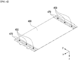
FIG. 4 is an exploded perspective view of a battery module according to an embodiment of the present disclosure. -
FIG. 5 is a perspective view showing a state in which the components constituting the battery module ofFIG. 4 are combined. -
FIG. 6 is a perspective view showing a state in which the upper portion of the module frame of the battery module ofFIG. 4 is turned over in the up and down direction. -
FIG. 7 is a perspective view showing a state in which the upper portion of the module frame is removed from the battery module ofFIG. 4 . -
FIG. 8 is a cross-sectional view taken along the cutting line B-B ofFIG. 4 . -
FIG. 9 is an exploded perspective view of a battery module according to another embodiment of the present disclosure. -
FIG. 10 is a perspective view showing a state in which the battery module ofFIG. 9 is turned over in the up and down direction. - Hereinafter, various embodiments of the present disclosure will be described in detail with reference to the accompanying drawings so that those skilled in the art can easily implement them. The present disclosure may be modified in various different ways, and is not limited to the embodiments set forth herein.
- Portions that are irrelevant to the description will be omitted to clearly describe the present disclosure, and like reference numerals designate like elements throughout the specification.
- Further, in the figures, the size and thickness of each element are arbitrarily illustrated for convenience of description, and the present disclosure is not necessarily limited to those illustrated in the figures. In the figures, the thickness of layers, regions, etc. are exaggerated for clarity. In the figures, for convenience of description, the thicknesses of some layers and regions are shown to be exaggerated.
- Further, throughout the specification, when a portion is referred to as "including" a certain component, it means that the portion can further include other components, without excluding the other components, unless otherwise stated.
- Further, throughout the specification, when referred to as "planar", it means when a target portion is viewed from the upper side, and when referred to as "cross-sectional", it means when a target portion is viewed from the side of a cross section cut vertically.
- In the following, the battery module according to an embodiment of the present disclosure will be described. However, the description herein is made based on the front surface of the front and rear surfaces of the battery module, without being limited thereto, and even in the case of the rear surface, the same or similar contents may be described.
-
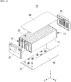
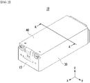
FIG. 4 is an exploded perspective view of a battery module according to an embodiment of the present disclosure.FIG. 5 is a perspective view showing a state in which the components constituting the battery module ofFIG. 4 are combined. - Referring to
FIGS. 4 and5 , thebattery module 100 according to the present embodiment includes abattery cell stack 120 in which a plurality ofbattery cells 110 are stacked in a first direction (y-axis), amodule frame 200 that houses thebattery cell stack 120,end plates 150 located at the front surface and the rear surface of thebattery cell stack 120, respectively, and abusbar frame 130 located between thebattery cell stack 120 and theend plate 150. Themodule frame 200 includes aU-shaped frame 300 of which an upper surface, a front surface and a rear surface are opened, and anupper plate 400 that covers the upper portion of thebattery cell stack 120. - The
battery module 100 according to this embodiment may be configured such that a first thermallyconductive resin layer 310 is located between thebattery cell stack 120 and the bottom surface of theU-shaped frame 300. In the first thermallyconductive resin layer 310, before thebattery cell stack 120 is mounted on the bottom surface of theU-shaped frame 300, a thermally conductive resin can be coated onto the bottom surface of theU-shaped frame 300. Thereafter, the thermally conductive resin can be cured, thereby forming the first thermallyconductive resin layer 310. Thereby, the first thermallyconductive resin layer 310 can fix thebattery cell stack 120 while transferring heat generated from thebattery cell 110 to the bottom of thebattery module 100. -
FIG. 6 is a perspective view showing a state in which the upper portion of the module frame of the battery module ofFIG. 4 is turned over in the up and down direction.FIG. 7 is a perspective view showing a state in which the upper portion of the module frame is removed from the battery module ofFIG. 4 . - Referring to
FIGS. 6 and7 , in thebattery module 100 according to the present embodiment, at least onefirst injection hole 450 can be formed in theupper plate 400 and thus, a thermally conductive resin can be injected into thefirst injection hole 450. Thereafter, the thermally conductive resin can be cured, thereby forming the second thermallyconductive resin layer 160. - The
first injection hole 450 may be formed on theupper plate 400. Thefirst injection hole 450 can be formed at a position adjacent to the end part of theupper plate 400. Thefirst injection hole 450 may include at least two injection holes, and the at least two injection holes are adjacent to both ends of theupper plate 400, but may be formed at positions opposite to each other. Further, the first injection holes 450 may be formed at one end part of theupper plate 400, with at least two injection holes being spaced apart from each other. In this case, the first injection holes 450 may be similarly formed in the opposite end part of theupper plate 400, with at least two injection holes being spaced apart from each other. - Referring to the conventional battery cell of
FIGS. 1 to 3 , thefirst injection hole 450 may be formed at a position corresponding to a position of thebattery cell 110 having the lowest cooling efficiency. Thereby, the second thermallyconductive resin layer 160 formed by injecting the thermally conductive resin into thefirst injection hole 450 may be formed at a position corresponding to a position of thebattery cell 110 having the lowest cooling efficiency. Consequently, thebattery module 100 according to the present embodiment can improve cooling efficiency of thebattery cell 110, and can reduce a temperature difference according to the position of thebattery cell 110. - When the first injection holes 450 are formed at one end part of the
upper plate 400, with at least two injection holes being spaced apart from each other, the at least two injection holes may be located separately from each other in a direction corresponding to the first direction (y-axis). Thereby, thebattery module 100 according to the present embodiment can evenly inject the second thermallyconductive resin layer 160 in a direction corresponding to the first direction, as compared with a structure that is injected and formed by one injection hole. Through this, thebattery module 100 according to the present embodiment can evenly improve the cooling efficiency of thebattery cells 110 regardless of the position of the battery cell stack, and also evenly reduce the temperature difference according to the position of thebattery cell 110. - Referring to
FIGS. 6 and7 , thebattery module 100 according to the present embodiment may be configured such that at least two blockingpads 470 are located on the lower surface of theupper plate 400. At least two blockingpads 470 may be extended in a direction corresponding to the first direction (y-axis). At least two blockingpads 470 may be protruded in a direction corresponding to a direction (z-axis) toward thebattery cell stack 120. Preferably, the at least two blockingpads 470 are protruded in a direction corresponding to a direction (z-axis) toward the battery cell stack, and may make contact with the upper portion of the battery cell stack. Therefore, the blockingpads 470 may block the thermally conductive resin injected into thefirst injection hole 450 from being coated onto a region outside the blockingpads 470. - The
first injection hole 450 may be located between at least two blockingpads 470. Thereby, the second thermally conductive resin layers 160 may be formed at a position corresponding to a region between the at least two blockingpads 470. That is, the blockingpads 470 can adjust a region in which the second thermallyconductive resin layer 160 can be formed, and also can prevent the thermally conductive resin injected into thefirst injection hole 450 from being injected into an unnecessary region. - As an example, the region corresponding to the central portion of the
battery cell 11 is sufficiently cooled with only the thermallyconductive resin layer 31 located at the lower portion. This is because in the embodiment of the present disclosure, it is not necessary to form the second thermallyconductive resin layer 160 up to a region corresponding to the central portion of thebattery cell 110. Thereby, the blockingpads 470 are more preferably formed at a position adjacent to the region corresponding to both ends of thebattery cell 110. - Further, the blocking
pads 470 limit the region to which the thermally conductive resin is coated, so that the heat conductive resin can be uniformly coated onto a desired position without going through the additional disassembly and assembly process of thebattery module 100. In addition, the blockingpads 470 can reduce the cost loss for the thermally conductive resin injected up to a region where the thermally conductive resin is unnecessary. -
FIG. 8 is a cross-sectional view taken along the cutting line B-B ofFIG. 4 . Referring toFIGS. 4 to 8 , a first thermallyconductive resin layer 310 is in contact with a lower portion of thebattery cell stack 120 included in thebattery module 100, and at least a certain region of the upper portion of thebattery cell stack 120 can be structured to make contact with the second thermallyconductive resin layer 160. Thereby, unlike theconventional battery module 10, thebattery module 100 has a structure that cools both the upper portion and the lower portion of thebattery cell stack 120, which is a structure in which heat generated from thebattery cell stack 12 flows in the second cooling direction D2 directing both the upper portion and the lower portion. - Thereby, unlike the
conventional battery module 10, thebattery module 100 according to the present embodiment can cool the heat generated in a direction toward the upper portion and both end portions of thebattery cell stack 120 via the second thermallyconductive resin layer 160. Thereby, thebattery module 100 according to the present embodiment can suppress a local temperature rise that occurs at both end portions of thebattery cell 110, and can reduce a temperature difference in the battery cell. In addition, it is possible to prevent the output of the battery including thebattery cell 110 from being limited at an early stage. -
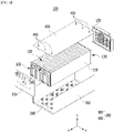
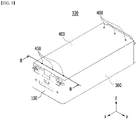
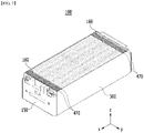
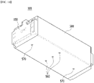
FIG. 9 is an exploded perspective view of a battery module according to another embodiment of the present disclosure.FIG. 10 is a perspective view showing a state in which the battery module ofFIG. 9 is turned over in the up and down direction. - Referring to
FIGS. 9 and10 , thebattery module 101 according to the present embodiment is described based on the same contents as thebattery module 100 described inFIGS. 5 to 9 , and only different parts will be described in detail. - The
battery module 101 according to the present embodiment includes amodule frame 500, and themodule frame 500 includes a module frame (or a mono frame) including upper and lower portions corresponding to each other, and both side portions corresponding to each other which house thebattery cell stack 110. - The
battery module 101 according to the present embodiment may be configured such that at least onefirst injection hole 550 is formed in the upper portion of themodule frame 500, and details of thefirst injection hole 550 are the same as those of thefirst injection hole 450 described with reference toFIGS. 5 to 9 . Additionally, thebattery module 101 according to the present embodiment may be configured such that at least onesecond injection hole 560 is formed in the lower portion of themodule frame 500. Here, the at least onesecond injection hole 560 may be formed at a position corresponding to the central region of the lower portion of themodule frame 500. - Further, the
battery module 101 according to the present embodiment may be configured such that at least onechecking hole 570 is formed in the lower portion of themodule frame 500. At least onechecking hole 570 may be formed at a position adjacent to the lower end portion of themodule frame 500, and may be formed to be spaced apart from thesecond injection hole 560. Thereby, when the thermally conductive resin injected through thesecond injection hole 560 is injected more than necessary, the thermally conductive resin may be discharged to the outside of thebattery module 101 via thechecking hole 570, whereby the injection amount may be adjusted. - However, the
module frame 500 is not limited thereto, and may be replaced with a frame having a shape in which two L-shaped frames are combined. In this case as well, first injection holes 450 and 550 may be formed on the upper portion of themodule frame 500, and a thermally conductive resin may be coated in advance onto the lower portion of themodule frame 500 like a U-shaped frame, or a thermally conductive resin may be injected via a separate injection hole. - Meanwhile, one or more of the battery modules according to the embodiment of the present disclosure can be packaged in a pack case to form a battery pack.
- The above-mentioned battery module and a battery pack may be applied to various devices. These devices may be applied to transportation means such as an electric bicycle, an electric vehicle, a hybrid vehicle, but the present disclosure is not limited thereto but can be applied to transportation means such as an electric bicycle, an electric vehicle, a hybrid vehicle, but the present disclosure is not limited thereto and can be applied to various devices that can use the battery module and the battery pack including the same, which also belongs to the scope of the present disclosure.
- Although the preferred embodiments of the present disclosure have been described in detail above, the scope of the present disclosure is not limited thereto, and various modifications and improvements of those skilled in the art using the basic concepts of the present disclosure defined in the following claims also belong to the scope of rights.
-
- 100: battery module
- 110: battery cell
- 120: battery cell stack
- 300: U-shaped frame
- 400: upper plate
- 500: mono frame
Claims (12)
- A battery module comprising:a battery cell stack in which a plurality of battery cells are stacked in a first direction,a module frame for housing the battery cell stack,a first thermally conductive resin layer located between the battery cell stack and a lower portion of the module frame, anda second thermally conductive resin layer located between the battery cell stack and an upper portion of the module frame,wherein at least one first injection hole for injecting a thermally conductive resin is formed in the upper portion of the module frame.
- The battery module of claim 1,
wherein the at least one first injection hole is formed at a position adjacent to an upper end of the module frame. - The battery module of claim 2,
wherein the at least one first injection hole is formed at a position adjacent to both ends of the upper portion of the module frame, and is formed at positions opposite to each other. - The battery module of claim 2,
wherein the at least two first injection holes are formed at positions adjacent to one end of the upper portion of the module frame, and are located separately from each other in the same direction as the first direction. - The battery module of claim 1,wherein the module frame comprises a U-shaped frame including a bottom portion and two side surface portions connected to both sides of the bottom portion, and an upper plate that covers the battery cell stack mounted on the U-shaped frame, andfurther comprises at least two blocking pads located on the lower surface of the upper plate,wherein the first injection hole is located between the at least two pads.
- The battery module of claim 5,
wherein the second thermally conductive resin layer is formed at a position corresponding to a region between the blocking pads. - The battery module of claim 5,wherein the blocking pad is extended in the same direction as the first direction, andthe blocking pad is protruded in a direction toward the battery cell stack.
- The battery module of claim 5,
wherein the thermally conductive resin layer is formed by coating a thermally conductive resin onto the lower frame of the U-shaped frame. - The battery module of claim 1,wherein the module frame comprises a module frame including an upper portion and a lower portion corresponding to each other, and both side portions corresponding to each other, which house the battery cell stack, andat least one second injection hole is located at the lower portion of the module frame.
- The battery module of claim 9,
wherein the thermally conductive resin layer is formed by injecting a thermally conductive resin into the at least one second injection hole. - The battery module of claim 9,
wherein the at least one second injection hole is formed at a position corresponding to a central region of the lower surface of the module frame. - A battery pack comprising the battery module as set forth in claim 1.
Applications Claiming Priority (2)
| Application Number | Priority Date | Filing Date | Title |
|---|---|---|---|
| KR1020200074749A KR102821615B1 (en) | 2020-06-19 | 2020-06-19 | Battery module and battery pack including the same |
| PCT/KR2021/002554 WO2021256661A1 (en) | 2020-06-19 | 2021-03-02 | Battery module and battery pack including same |
Publications (2)
| Publication Number | Publication Date |
|---|---|
| EP4040575A1 true EP4040575A1 (en) | 2022-08-10 |
| EP4040575A4 EP4040575A4 (en) | 2023-01-04 |
Family
ID=79178062
Family Applications (1)
| Application Number | Title | Priority Date | Filing Date |
|---|---|---|---|
| EP21827060.1A Pending EP4040575A4 (en) | 2020-06-19 | 2021-03-02 | BATTERY MODULE AND BATTERY PACK COMPRISING THEM |
Country Status (6)
| Country | Link |
|---|---|
| US (1) | US12224416B2 (en) |
| EP (1) | EP4040575A4 (en) |
| JP (1) | JP7408219B2 (en) |
| KR (1) | KR102821615B1 (en) |
| CN (1) | CN114762174B (en) |
| WO (1) | WO2021256661A1 (en) |
Families Citing this family (3)
| Publication number | Priority date | Publication date | Assignee | Title |
|---|---|---|---|---|
| CN109994798B (en) * | 2017-12-26 | 2025-08-15 | Sk新能源株式会社 | Battery module and method for manufacturing same |
| EP4328993A4 (en) | 2021-11-15 | 2025-07-02 | Lg Energy Solution Ltd | ELECTRODE AND ELECTRODE MANUFACTURING PROCESS |
| KR20250096443A (en) * | 2023-12-20 | 2025-06-27 | 주식회사 엘지에너지솔루션 | Battery module and battery pack including the same |
Family Cites Families (15)
| Publication number | Priority date | Publication date | Assignee | Title |
|---|---|---|---|---|
| KR101560217B1 (en) * | 2012-09-19 | 2015-10-15 | 주식회사 엘지화학 | Battery Module of Improved Cooling Efficiency |
| KR102187056B1 (en) | 2016-12-20 | 2020-12-04 | 주식회사 엘지화학 | Battery Module having improved energy density and simplified assembly process |
| KR102201348B1 (en) * | 2017-01-17 | 2021-01-08 | 주식회사 엘지화학 | Fabricating method of battery module |
| KR102207881B1 (en) * | 2017-01-17 | 2021-01-25 | 주식회사 엘지화학 | Battery module, battery pack comprising the battery module and vehicle comprising the battery pack |
| CN109428020B (en) | 2017-08-31 | 2024-04-16 | 宁德时代新能源科技股份有限公司 | Frame and battery module |
| CN109428021B (en) * | 2017-08-31 | 2024-04-02 | 宁德时代新能源科技股份有限公司 | Frame and battery module |
| US10601003B2 (en) * | 2017-10-30 | 2020-03-24 | Lg Chem, Ltd. | Battery module and method of assembling the battery module |
| KR102128588B1 (en) * | 2017-12-26 | 2020-07-08 | 에스케이이노베이션 주식회사 | Battery module and its manufacturing method |
| CN109994798B (en) * | 2017-12-26 | 2025-08-15 | Sk新能源株式会社 | Battery module and method for manufacturing same |
| KR102388127B1 (en) | 2018-01-31 | 2022-04-19 | 주식회사 엘지에너지솔루션 | Top cover, battery module using the same, and battery pack and vehicle including the same |
| KR102150679B1 (en) * | 2018-03-13 | 2020-09-01 | 주식회사 엘지화학 | Battery module, battery pack comprising the battery module and vehicle comprising the battery pack |
| KR102070573B1 (en) * | 2018-04-20 | 2020-01-29 | 주식회사 엘지화학 | Resin composition and battery module comprising the same |
| KR102268268B1 (en) | 2018-04-20 | 2021-06-23 | 주식회사 엘지화학 | Resin composition and battery module comprising the same |
| KR102389911B1 (en) | 2018-09-17 | 2022-04-21 | 주식회사 엘지에너지솔루션 | Battery Module Having Module Housing |
| KR102378527B1 (en) | 2018-12-05 | 2022-03-23 | 주식회사 엘지에너지솔루션 | Battery module and the method of manufacturing the same |
-
2020
- 2020-06-19 KR KR1020200074749A patent/KR102821615B1/en active Active
-
2021
- 2021-03-02 EP EP21827060.1A patent/EP4040575A4/en active Pending
- 2021-03-02 JP JP2022526465A patent/JP7408219B2/en active Active
- 2021-03-02 US US17/779,950 patent/US12224416B2/en active Active
- 2021-03-02 CN CN202180006852.XA patent/CN114762174B/en active Active
- 2021-03-02 WO PCT/KR2021/002554 patent/WO2021256661A1/en not_active Ceased
Also Published As
| Publication number | Publication date |
|---|---|
| US12224416B2 (en) | 2025-02-11 |
| CN114762174A (en) | 2022-07-15 |
| JP7408219B2 (en) | 2024-01-05 |
| JP2023500943A (en) | 2023-01-11 |
| KR102821615B1 (en) | 2025-06-16 |
| WO2021256661A1 (en) | 2021-12-23 |
| KR20210157005A (en) | 2021-12-28 |
| US20230006274A1 (en) | 2023-01-05 |
| CN114762174B (en) | 2025-09-23 |
| EP4040575A4 (en) | 2023-01-04 |
Similar Documents
| Publication | Publication Date | Title |
|---|---|---|
| US10873114B2 (en) | Secondary battery module | |
| US12548822B2 (en) | Battery pack and device including the same | |
| US12155050B2 (en) | Battery module and battery pack including the same | |
| US20230299431A1 (en) | Battery cell, battery module, and battery pack including the same | |
| EP4170796A1 (en) | Battery module and battery pack including same | |
| US12224416B2 (en) | Battery module and battery pack including the same | |
| KR20210042582A (en) | Battery module and battery pack including the same | |
| US12451540B2 (en) | Battery module and battery pack including the same | |
| US20250364630A1 (en) | Battery Module and Battery Pack Including the Same | |
| US12046731B2 (en) | Battery module, method for preparing the same and battery pack including the same | |
| EP4142020B1 (en) | Battery module and battery pack including the same | |
| EP4120441B1 (en) | Battery module and battery pack including the same | |
| JP2023530687A (en) | Battery modules and battery packs containing the same | |
| KR20230008531A (en) | Battery module, battery pack including the same and manufacturing method of secondary battery |
Legal Events
| Date | Code | Title | Description |
|---|---|---|---|
| STAA | Information on the status of an ep patent application or granted ep patent |
Free format text: STATUS: THE INTERNATIONAL PUBLICATION HAS BEEN MADE |
|
| PUAI | Public reference made under article 153(3) epc to a published international application that has entered the european phase |
Free format text: ORIGINAL CODE: 0009012 |
|
| STAA | Information on the status of an ep patent application or granted ep patent |
Free format text: STATUS: REQUEST FOR EXAMINATION WAS MADE |
|
| 17P | Request for examination filed |
Effective date: 20220504 |
|
| AK | Designated contracting states |
Kind code of ref document: A1 Designated state(s): AL AT BE BG CH CY CZ DE DK EE ES FI FR GB GR HR HU IE IS IT LI LT LU LV MC MK MT NL NO PL PT RO RS SE SI SK SM TR |
|
| A4 | Supplementary search report drawn up and despatched |
Effective date: 20221205 |
|
| RIC1 | Information provided on ipc code assigned before grant |
Ipc: H01M 50/20 20210101ALI20221129BHEP Ipc: H01M 50/24 20210101ALI20221129BHEP Ipc: H01M 10/617 20140101ALI20221129BHEP Ipc: H01M 10/653 20140101AFI20221129BHEP |
|
| DAV | Request for validation of the european patent (deleted) | ||
| DAX | Request for extension of the european patent (deleted) | ||
| STAA | Information on the status of an ep patent application or granted ep patent |
Free format text: STATUS: EXAMINATION IS IN PROGRESS |
|
| 17Q | First examination report despatched |
Effective date: 20240913 |