EP4040463A1 - Quick closing structure suitable for dc circuit breaker and dc circuit breaker - Google Patents
Quick closing structure suitable for dc circuit breaker and dc circuit breaker Download PDFInfo
- Publication number
- EP4040463A1 EP4040463A1 EP22305135.0A EP22305135A EP4040463A1 EP 4040463 A1 EP4040463 A1 EP 4040463A1 EP 22305135 A EP22305135 A EP 22305135A EP 4040463 A1 EP4040463 A1 EP 4040463A1
- Authority
- EP
- European Patent Office
- Prior art keywords
- cam
- closing
- movable contact
- circuit breaker
- mating
- Prior art date
- Legal status (The legal status is an assumption and is not a legal conclusion. Google has not performed a legal analysis and makes no representation as to the accuracy of the status listed.)
- Withdrawn
Links
- 230000013011 mating Effects 0.000 claims description 63
- 238000002679 ablation Methods 0.000 description 2
- 230000001419 dependent effect Effects 0.000 description 2
- 238000010586 diagram Methods 0.000 description 2
- 230000006870 function Effects 0.000 description 2
- 230000007547 defect Effects 0.000 description 1
- 238000000034 method Methods 0.000 description 1
- 238000012986 modification Methods 0.000 description 1
- 230000004048 modification Effects 0.000 description 1
Images




Classifications
-
- H—ELECTRICITY
- H01—ELECTRIC ELEMENTS
- H01H—ELECTRIC SWITCHES; RELAYS; SELECTORS; EMERGENCY PROTECTIVE DEVICES
- H01H71/00—Details of the protective switches or relays covered by groups H01H73/00 - H01H83/00
- H01H71/10—Operating or release mechanisms
- H01H71/50—Manual reset mechanisms which may be also used for manual release
- H01H71/52—Manual reset mechanisms which may be also used for manual release actuated by lever
- H01H71/526—Manual reset mechanisms which may be also used for manual release actuated by lever the lever forming a toggle linkage with a second lever, the free end of which is directly and releasably engageable with a contact structure
-
- H—ELECTRICITY
- H01—ELECTRIC ELEMENTS
- H01H—ELECTRIC SWITCHES; RELAYS; SELECTORS; EMERGENCY PROTECTIVE DEVICES
- H01H3/00—Mechanisms for operating contacts
- H01H3/32—Driving mechanisms, i.e. for transmitting driving force to the contacts
- H01H3/42—Driving mechanisms, i.e. for transmitting driving force to the contacts using cam or eccentric
-
- H—ELECTRICITY
- H01—ELECTRIC ELEMENTS
- H01H—ELECTRIC SWITCHES; RELAYS; SELECTORS; EMERGENCY PROTECTIVE DEVICES
- H01H33/00—High-tension or heavy-current switches with arc-extinguishing or arc-preventing means
- H01H33/02—Details
- H01H33/59—Circuit arrangements not adapted to a particular application of the switch and not otherwise provided for, e.g. for ensuring operation of the switch at a predetermined point in the AC cycle
- H01H33/596—Circuit arrangements not adapted to a particular application of the switch and not otherwise provided for, e.g. for ensuring operation of the switch at a predetermined point in the AC cycle for interrupting DC
Definitions
- the present disclosure relates to a quick closing structure suitable for DC circuit breakers.
- the present disclosure also relates to a DC circuit breaker including the quick closing structure as described above.
- a quick closing structure suitable for DC circuit breaker is proposed, which is directly installed on the housing of the DC circuit breaker, so that the quick closing structure is not located between the operating handle of the DC circuit breaker and the magnetic assembly of the DC circuit breaker.
- the quick closing structure includes a closing cam.
- the closing cam includes a cam through hole.
- a first shaft provided on the housing is mated in the cam through hole, so that the closing cam can rotate relative to the housing around the first shaft.
- the closing cam further includes a cam recess and a cam mating portion having an arc surface.
- the cam mating portion extends relative to the cam through hole so as to form an angle with the surface of the closing cam.
- the cam recess is communicated with the cam through hole.
- the quick closing structure further includes a cam pressing plate.
- the cam pressing plate comprises a pressing plate mating portion and a pressing plate connecting portion.
- a pressing plate step is formed between the pressing plate mating portion and the pressing plate connecting portion.
- a mating blind hole is disposed in the pressing plate mating portion.
- a connecting through hole is disposed in the pressing plate connecting portion.
- one end of the first shaft provided on the housing is mated in the mating blind hole.
- a second shaft provided on the housing is mated in the connecting through hole.
- the cam pressing plate presses the closing cam against the inner surface of the housing.
- the quick closing structure further includes a closing cam return spring.
- the closing cam return spring is sleeved on the second shaft and located between the housing and the cam pressing plate.
- One end of the closing cam return spring acts on the housing.
- the other end of the closing cam return spring abuts against and is mated in the cam recess.
- a plurality of elongated bulges are provided along the inner circumferential surface of the connecting through hole.
- the bulges abut against the outer circumferential surface of the second shaft.
- the movable contact bracket of the movable contact assembly of the DC circuit breaker has a first mating surface and a second mating surface.
- the first mating surface and the second mating surface are connected together by the arc surface of the bracket.
- the closing cam abuts against the inner surface of the housing under the action of the closing cam return spring, and the arc surface of the cam mating portion does not contact the first mating surface of the movable contact bracket of the movable contact assembly.
- the first mating surface of the movable contact bracket is in frictional contact with the arc surface of the cam mating portion, and the contact position between them changes with the rotation of the movable contact bracket, the frictional contact slows down the closing movement of the movable contact assembly.
- a DC breaker which includes the quick closing structure as described above.
- the quick closing structure since the quick closing structure is not installed on the operating handle, the functional surfaces of the movable contact bracket and the quick closing structure will not occupy the space of the magnetic assembly, which can give more space for the design of the size of the magnetic assembly, arrangement of the parts and the like to meet the requirements of the product for high breaking performance.
- the quick closing structure according to the present disclosure requires less space and saves space.
- the movable contact bracket of the movable contact assembly always moves when it realizes the function of quick closing, which reduces the friction force of the working surface and reduces the requirement of material strength.
- the quick closing structure according to the present disclosure is easy to assemble, simple in structure and reliable in performance. Fast closing can effectively reduce contact ablation and prolong service life.
- a quick closing structure 2 suitable for DC circuit breaker 1 is proposed, wherein Fig. 1 shows the internal structure of DC circuit breaker 1 in the open position (movable contact is separated from stationary contact), and Fig. 2 shows the internal structure of DC circuit breaker 1 in the closed position (movable contact is closed with stationary contact), the quick closing structure 2 is directly installed on the housing 3 of the DC breaker 1 (installed in the upper right corner of the housing 3 in Fig. 1 ), so that the quick closing structure 2 is not located between the operating handle 4 of the DC breaker and the magnetic assembly 5 of the DC breaker.
- the quick closing structure 2 includes a closing cam 6.
- the closing cam 6 includes a cam through hole 6-1.
- a first shaft 3-1 provided on the housing 3 (as shown in Fig. 4 ) is mated in the cam through hole 6-1, so that the closing cam 6 can rotate relative to the housing 3 around the first shaft 3-1.
- the closing cam 6 further includes a cam recess 6-3 and a cam mating portion 6-2 having an arc surface 6-2-1.
- the cam mating portion 6-2 extends relative to the cam through hole 6-1 so as to form an angle with the surface 6-4 of the closing cam 6.
- the cam recess 6-3 is communicated with the cam through hole 6-1.
- the quick closing structure 2 further includes a cam pressing plate 7.
- the cam pressing plate 7 comprises a pressing plate mating portion 7-1 and a pressing plate connecting portion 7-2.
- a pressing plate step 7-3 is formed between the pressing plate mating portion 7-1 and the pressing plate connecting portion 7-2.
- a mating blind hole 7-1-1 is disposed in the pressing plate mating portion 7-1.
- a connecting through hole 7-2-1 is disposed in the pressing plate connecting portion 7-2.
- one end of the first shaft 3-1 provided on the housing is mated in the mating blind hole 7-1-1.
- a second shaft 3-2 provided on the housing 3 is mated in the connecting through hole.
- the cam pressing plate 7 presses the closing cam 6 against the inner surface of the housing 3.
- the quick closing structure 2 further includes a closing cam return spring 8.
- the closing cam return spring 8 is sleeved on the second shaft 3-2 and located between the housing 3 and the cam pressing plate 7.
- One end 8-1 of the closing cam return spring 8 acts on the housing.
- the other end 8-2 of the closing cam return spring 8 abuts against and is mated in the cam recess 6-3.
- a plurality of elongated bulges 7-2-2 are provided along the inner circumferential surface of the connecting through hole 7-2-1.
- the bulges 7-2-2 abut against the outer circumferential surface of the second shaft 3-2, so that a tight fit is formed between the second shaft 3-2 and the cam pressing plate 7.
- the movable contact bracket 10 of the movable contact assembly 9 of the DC breaker 1 has a first mating surface 10-1 and a second mating surface 10-2.
- the operating handle 4 of the DC circuit breaker 1 is rotatably installed in the housing 3 and connected to the movable contact assembly 9 through the handle lever 12.
- the movable contact bracket 10 is rotatably connected to the movable contact assembly 9 which is rotatably connected to the housing 3 of the DC breaker 1.
- first mating surface 10-1 and the second mating surface 10-2 are connected together by a bracket arc surface 10-3.
- the first mating surface 10-1 of the movable contact bracket 10 is in frictional contact with the arc surface 6-2-1 of the cam mating portion 6-2, and the contact position between them changes with the rotation of the movable contact bracket, the frictional contact slows down the closing movement of the movable contact assembly 9.
- a DC breaker 1 which includes the quick closing structure 2 as described above.
- the functional surfaces of the movable contact bracket and the quick closing structure 2 will not occupy the space of the magnetic assembly 5, which can give more space for the design of the size of the magnetic assembly, arrangement of the parts and the like to meet the requirements of the product for high breaking performance.
- the quick closing structure according to the present disclosure requires less space and saves space.
- the movable contact bracket of the movable contact assembly always moves when it realizes the function of quick closing, which reduces the friction force of the working surface and reduces the requirement of material strength.
- the quick closing structure according to the present disclosure is easy to assemble, simple in structure and reliable in performance. Fast closing can effectively reduce contact ablation and prolong service life.
- any element, action or instruction used herein should not be interpreted as critical or necessary.
- the articles “a” and “an” are intended to include one or more items and can be used interchangeably with “one or more”.
- the article “the” is intended to include one or more items cited in conjunction with the article “the” and can be used interchangeably with “one or more”.
- the term “set” is intended to include one or more items (such as related items, unrelated items, a combination of related and unrelated items, etc.), and can be used interchangeably with “one or more”. If only one item is intended, the phrase “only one item” or similar language will be used.
- the term “has” and its variants are intended to be open terms.
- the phrase “based on” is intended to mean “based at least in part on”, unless explicitly stated otherwise.
- the term “or” is intended to be inclusive when used in series, and can be used interchangeably with “and/or”, unless otherwise explicitly stated (for example, if used in combination with “or” or “only one of them”).
Landscapes
- Breakers (AREA)
- Driving Mechanisms And Operating Circuits Of Arc-Extinguishing High-Tension Switches (AREA)
Abstract
Description
- The present disclosure relates to a quick closing structure suitable for DC circuit breakers. The present disclosure also relates to a DC circuit breaker including the quick closing structure as described above.
- In the DC circuit breaker in the prior art, since the quick closing element is installed on the operating handle, the functional surfaces of the movable contact bracket and the quick closing element occupy the space of the magnetic assembly, which leads to the design of the size of the magnetic assembly and the arrangement of parts and the like cannot meet the requirements of the product for high breaking performance.
- In order to solve one or more defects in the prior art, according to one aspect of the present disclosure, a quick closing structure suitable for DC circuit breaker is proposed, which is directly installed on the housing of the DC circuit breaker, so that the quick closing structure is not located between the operating handle of the DC circuit breaker and the magnetic assembly of the DC circuit breaker.
- According to the above aspect of the present disclosure, the quick closing structure includes a closing cam.
- The closing cam includes a cam through hole.
- A first shaft provided on the housing is mated in the cam through hole, so that the closing cam can rotate relative to the housing around the first shaft.
- According to the above aspects of the present disclosure, the closing cam further includes a cam recess and a cam mating portion having an arc surface.
- The cam mating portion extends relative to the cam through hole so as to form an angle with the surface of the closing cam.
- The cam recess is communicated with the cam through hole.
- According to the above aspects of the present disclosure, the quick closing structure further includes a cam pressing plate.
- The cam pressing plate comprises a pressing plate mating portion and a pressing plate connecting portion.
- A pressing plate step is formed between the pressing plate mating portion and the pressing plate connecting portion.
- A mating blind hole is disposed in the pressing plate mating portion.
- A connecting through hole is disposed in the pressing plate connecting portion.
- According to the above aspects of the present disclosure, one end of the first shaft provided on the housing is mated in the mating blind hole.
- A second shaft provided on the housing is mated in the connecting through hole.
- The cam pressing plate presses the closing cam against the inner surface of the housing.
- According to the above aspects of the present disclosure, the quick closing structure further includes a closing cam return spring.
- The closing cam return spring is sleeved on the second shaft and located between the housing and the cam pressing plate.
- One end of the closing cam return spring acts on the housing.
- The other end of the closing cam return spring abuts against and is mated in the cam recess.
- According to the above aspects of the present disclosure, a plurality of elongated bulges are provided along the inner circumferential surface of the connecting through hole.
- The bulges abut against the outer circumferential surface of the second shaft.
- According to the above aspects of the present disclosure, the movable contact bracket of the movable contact assembly of the DC circuit breaker has a first mating surface and a second mating surface.
- The first mating surface and the second mating surface are connected together by the arc surface of the bracket.
- According to the above aspects of the disclosure, when the movable contact assembly of the DC circuit breaker is in the open position with respect to the stationary contact assembly of the DC circuit breaker, the closing cam abuts against the inner surface of the housing under the action of the closing cam return spring, and the arc surface of the cam mating portion does not contact the first mating surface of the movable contact bracket of the movable contact assembly.
- During the movement of the movable contact assembly relative to the stationary contact assembly from the open position to the closed position, the first mating surface of the movable contact bracket is in frictional contact with the arc surface of the cam mating portion, and the contact position between them changes with the rotation of the movable contact bracket, the frictional contact slows down the closing movement of the movable contact assembly.
- When the arc surface of the cam mating portion is out of contact with the first mating surface of the movable contact bracket and comes into contact with the arc surface of the bracket, the force applied by the movable contact bracket to the closing cam causes the closing cam to press the housing.
- When the arc surface of the cam mating portion is out of contact with the arc surface of the bracket, under the action of torque generated by the pressure of the arc surface of the bracket, the closing cam quickly hits the second mating surface of the movable contact bracket, so that the movable contact assembly quickly reaches the closing position, and the return spring is in a compressed state at this time.
- With the continuous closing action of the operating handle of the DC circuit breaker, the arc surface of the cam mating portion rests on the second mating surface of the movable contact bracket.
- According to another aspect of the present disclosure, a DC breaker is proposed, which includes the quick closing structure as described above.
- In the DC circuit breaker according to the present disclosure, since the quick closing structure is not installed on the operating handle, the functional surfaces of the movable contact bracket and the quick closing structure will not occupy the space of the magnetic assembly, which can give more space for the design of the size of the magnetic assembly, arrangement of the parts and the like to meet the requirements of the product for high breaking performance.
- The quick closing structure according to the present disclosure requires less space and saves space. The movable contact bracket of the movable contact assembly always moves when it realizes the function of quick closing, which reduces the friction force of the working surface and reduces the requirement of material strength. The quick closing structure according to the present disclosure is easy to assemble, simple in structure and reliable in performance. Fast closing can effectively reduce contact ablation and prolong service life.
- So far, in order that the detailed description of the disclosure here can be better understood, and in order that the contribution of the disclosure to the prior art can be better recognized, the disclosure has outlined the content of the disclosure quite extensively. Of course, embodiments of the present disclosure will be described below and will form the subject of the appended claims.
- Likewise, those skilled in the art will recognize that the concept on which this disclosure is based can easily be used as a basis for designing other structures, methods and systems for carrying out several purposes of this disclosure. Therefore, it is important that the appended claims should be regarded as including such equivalent structures as long as they do not exceed the spirit and scope of the present disclosure.
- Those skilled in the art will have a better understanding of the present disclosure through the following drawings, and the advantages of the present disclosure can be more clearly reflected. The drawings described here are only for illustrative purposes of selected embodiments, not all possible embodiments, and are intended not to limit the scope of the present disclosure.
-
Fig. 1 shows the internal structure of a DC circuit breaker in the open position according to the present disclosure; -
Fig. 2 shows the internal structure of a DC breaker in the closed position according to the present disclosure; -
Fig. 3 shows an assembly diagram of a quick closing structure according to the present disclosure; -
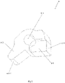
Fig. 4 shows a quick closing structure according to the present disclosure, in which the cam pressing plate is removed for clarity; -
Fig. 5 shows the closing cam of the quick closing structure according to the present disclosure; -
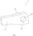
Figs. 6 and7 show the cam pressing plate of the quick closing structure according to the present disclosure; -
Fig. 8 shows the assembly schematic diagram of the cam pressing plate, the closing cam and the closing cam return spring of the quick closing structure according to the present disclosure; -
Fig. 9 shows the relative positional relationship between the movable contact assembly of the DC circuit breaker in the open position and the quick closing structure according to the present disclosure; -
Fig. 10 shows the relative positional relationship between the movable contact assembly of the DC circuit breaker in the closed position and the quick closing structure according to the present disclosure; -
Fig. 11 shows the relative positional relationship between the movable contact assembly of the DC circuit breaker in the open position and the quick closing structure according to the present disclosure, in which the operating handle and the handle lever are removed for clarity; -
Fig. 12 shows the relative positional relationship between the movable contact assembly of the DC circuit breaker in the closed position and the quick closing structure according to the present disclosure, in which the operating handle and the handle lever are removed for clarity. - Hereinafter, specific embodiments according to the present disclosure will be described in detail with reference to various drawings.
- According to one embodiment of the present disclosure, as shown in
Figs. 1 and2 , aquick closing structure 2 suitable forDC circuit breaker 1 is proposed, whereinFig. 1 shows the internal structure ofDC circuit breaker 1 in the open position (movable contact is separated from stationary contact), andFig. 2 shows the internal structure ofDC circuit breaker 1 in the closed position (movable contact is closed with stationary contact), thequick closing structure 2 is directly installed on thehousing 3 of the DC breaker 1 (installed in the upper right corner of thehousing 3 inFig. 1 ), so that thequick closing structure 2 is not located between theoperating handle 4 of the DC breaker and themagnetic assembly 5 of the DC breaker. - According to the above embodiment of the present disclosure, as shown in
fig. 3 , thequick closing structure 2 includes aclosing cam 6. - As shown in
Fig. 5 , theclosing cam 6 includes a cam through hole 6-1. - A first shaft 3-1 provided on the housing 3 (as shown in
Fig. 4 ) is mated in the cam through hole 6-1, so that theclosing cam 6 can rotate relative to thehousing 3 around the first shaft 3-1. - According to the above-mentioned various embodiments of the present disclosure, the
closing cam 6 further includes a cam recess 6-3 and a cam mating portion 6-2 having an arc surface 6-2-1. - The cam mating portion 6-2 extends relative to the cam through hole 6-1 so as to form an angle with the surface 6-4 of the
closing cam 6. - The cam recess 6-3 is communicated with the cam through hole 6-1.
- According to the above-mentioned various embodiments of the present disclosure, as shown in
Figs. 3 ,6 and7 , thequick closing structure 2 further includes acam pressing plate 7. - The
cam pressing plate 7 comprises a pressing plate mating portion 7-1 and a pressing plate connecting portion 7-2. - A pressing plate step 7-3 is formed between the pressing plate mating portion 7-1 and the pressing plate connecting portion 7-2.
- A mating blind hole 7-1-1 is disposed in the pressing plate mating portion 7-1.
- A connecting through hole 7-2-1 is disposed in the pressing plate connecting portion 7-2.
- According to the above-mentioned various embodiments of the present disclosure, one end of the first shaft 3-1 provided on the housing is mated in the mating blind hole 7-1-1.
- A second shaft 3-2 provided on the
housing 3 is mated in the connecting through hole. - The
cam pressing plate 7 presses theclosing cam 6 against the inner surface of thehousing 3. - According to the above-mentioned various embodiments of the present disclosure, the
quick closing structure 2 further includes a closingcam return spring 8. - As shown in
Figs. 4 and8 , the closingcam return spring 8 is sleeved on the second shaft 3-2 and located between thehousing 3 and thecam pressing plate 7. - One end 8-1 of the closing
cam return spring 8 acts on the housing. - The other end 8-2 of the closing
cam return spring 8 abuts against and is mated in the cam recess 6-3. - According to the above-mentioned various embodiments of the present disclosure, a plurality of elongated bulges 7-2-2 are provided along the inner circumferential surface of the connecting through hole 7-2-1.
- The bulges 7-2-2 abut against the outer circumferential surface of the second shaft 3-2, so that a tight fit is formed between the second shaft 3-2 and the
cam pressing plate 7. - According to the above-mentioned various embodiments of the present disclosure, as shown in
Figs. 9 to 12 , themovable contact bracket 10 of themovable contact assembly 9 of theDC breaker 1 has a first mating surface 10-1 and a second mating surface 10-2. The operating handle 4 of theDC circuit breaker 1 is rotatably installed in thehousing 3 and connected to themovable contact assembly 9 through thehandle lever 12. - The
movable contact bracket 10 is rotatably connected to themovable contact assembly 9 which is rotatably connected to thehousing 3 of theDC breaker 1. - As shown in
Fig. 9 , the first mating surface 10-1 and the second mating surface 10-2 are connected together by a bracket arc surface 10-3. - According to the above-mentioned various embodiments of the present disclosure, as shown in
Figs. 9 and11 , when themovable contact assembly 9 of the DC circuit breaker is in the open position with respect to thestationary contact assembly 11 of the DC circuit breaker, the closing cam 6 (surface 6-4 as shown inFig. 5 ) abuts against the inner surface of thehousing 3 under the action of the closingcam return spring 8, and the arc surface 6-2-1 of the cam mating portion 6-2 does not contact the first mating surface 10-1 of themovable contact bracket 10 of themovable contact assembly 9. - During the movement of the
movable contact assembly 9 relative to thestationary contact assembly 11 from the open position to the closed position, the first mating surface 10-1 of themovable contact bracket 10 is in frictional contact with the arc surface 6-2-1 of the cam mating portion 6-2, and the contact position between them changes with the rotation of the movable contact bracket, the frictional contact slows down the closing movement of themovable contact assembly 9. - When the arc surface 6-2-1 of the cam mating portion 6-2 is out of contact with the first mating surface 10-1 of the
movable contact bracket 10 and comes into contact with the arc surface 10-3 of the bracket, the force applied by themovable contact bracket 10 to theclosing cam 6 causes theclosing cam 6 to press thehousing 3. - As shown in
Figs. 10 and12 , when the arc surface 6-2-1 of the cam mating portion 6-2 is out of contact with the arc surface 10-3 of the bracket, under the action of torque generated by the pressure of the arc surface 10-3 of the bracket, theclosing cam 6 quickly hits the second mating surface 10-2 of themovable contact bracket 10, so that themovable contact assembly 9 quickly reaches the closing position, and thereturn spring 8 is in a compressed state at this time. - With the continuous closing action of the operating handle 4 of the DC circuit breaker, the arc surface 6-2-1 of the cam mating portion 6-2 rests on the second mating surface 10-2 of the
movable contact bracket 10. - According to another embodiment of the present disclosure, as shown in
Fig. 1 , aDC breaker 1 is proposed, which includes thequick closing structure 2 as described above. - In the DC circuit breaker according to the present disclosure, since the
quick closing structure 2 is not installed on theoperating handle 4, the functional surfaces of the movable contact bracket and thequick closing structure 2 will not occupy the space of themagnetic assembly 5, which can give more space for the design of the size of the magnetic assembly, arrangement of the parts and the like to meet the requirements of the product for high breaking performance. - The quick closing structure according to the present disclosure requires less space and saves space. The movable contact bracket of the movable contact assembly always moves when it realizes the function of quick closing, which reduces the friction force of the working surface and reduces the requirement of material strength. The quick closing structure according to the present disclosure is easy to assemble, simple in structure and reliable in performance. Fast closing can effectively reduce contact ablation and prolong service life.
- The above-mentioned disclosure provides illustration and description, but it is not intended to be exhaustive or to limit the embodiments to the precise forms disclosed. Modifications and changes can be made according to the above disclosure, or can be acquired from the practice of the embodiments.
- Even though specific combinations of features are recited in the claims and/or disclosed in the specification, these combinations are not intended to limit the disclosure of various embodiments. In fact, many of these features can be combined in ways not specifically described in the claims and/or not specifically disclosed in the specification. Although each dependent claim listed below may directly depend on only one claim, the disclosure of various embodiments includes each dependent claim combined with each other claim in the claim set.
- Unless explicitly stated, any element, action or instruction used herein should not be interpreted as critical or necessary. In addition, as used herein, the articles "a" and "an" are intended to include one or more items and can be used interchangeably with "one or more". In addition, as used herein, the article "the" is intended to include one or more items cited in conjunction with the article "the" and can be used interchangeably with "one or more". In addition, as used herein, the term "set" is intended to include one or more items (such as related items, unrelated items, a combination of related and unrelated items, etc.), and can be used interchangeably with "one or more". If only one item is intended, the phrase "only one item" or similar language will be used. In addition, as used herein, the term "has" and its variants are intended to be open terms. In addition, the phrase "based on" is intended to mean "based at least in part on", unless explicitly stated otherwise. In addition, as used herein, the term "or" is intended to be inclusive when used in series, and can be used interchangeably with "and/or", unless otherwise explicitly stated (for example, if used in combination with "or" or "only one of them").
Claims (10)
- A quick closing structure suitable for DC circuit breaker, characterized in that,
the quick closing structure is directly installed on a housing of the DC circuit breaker, so that the quick closing structure is not located between an operating handle of the DC circuit breaker and a magnetic assembly of the DC circuit breaker. - Quick closing structure according to claim 1, characterized in that,the quick closing structure includes a closing cam;the closing cam includes a cam through hole;a first shaft provided on the housing is mated in the cam through hole, so that the closing cam can rotate relative to the housing around the first shaft.
- Quick closing structure according to claim 2, characterized in that,the closing cam further includes a cam recess and a cam mating portion having an arc surface;the cam mating portion extends relative to the cam through hole so as to form an angle with the surface of the closing cam;the cam recess is communicated with the cam through hole.
- Quick closing structure according to claim 3, characterized in that,the quick closing structure further includes a cam pressing plate;the cam pressing plate comprises a pressing plate mating portion and a pressing plate connecting portion;a pressing plate step is formed between the pressing plate mating portion and the pressing plate connecting portion;a mating blind hole is disposed in the pressing plate mating portion;a connecting through hole is disposed in the pressing plate connecting portion.
- Quick closing structure according to claim 4, characterized in that,one end of the first shaft provided on the housing is mated in the mating blind hole;a second shaft provided on the housing is mated in the connecting through hole;the cam pressing plate presses the closing cam against the inner surface of the housing.
- Quick closing structure according to claim 5, characterized in that,the quick closing structure further includes a closing cam return spring;the closing cam return spring is sleeved on the second shaft and located between the housing and the cam pressing plate;one end of the closing cam return spring acts on the housing;the other end of the closing cam return spring abuts against and is mated in the cam recess.
- Quick closing structure according to claim 5, characterized in that,a plurality of elongated bulges are provided along the inner circumferential surface of the connecting through hole;the bulges abut against the outer circumferential surface of the second shaft.
- Quick closing structure according to claim 6, characterized in that,the movable contact bracket of the movable contact assembly of the DC circuit breaker has a first mating surface and a second mating surface;the first mating surface and the second mating surface are connected together by the arc surface of the bracket.
- Quick closing structure according to claim 8, characterized in that,when the movable contact assembly of the DC circuit breaker is in the open position with respect to the stationary contact assembly of the DC circuit breaker, the closing cam abuts against the inner surface of the housing under the action of the closing cam return spring, and the arc surface of the cam mating portion does not contact the first mating surface of the movable contact bracket of the movable contact assembly;during the movement of the movable contact assembly relative to the stationary contact assembly from the open position to the closed position, the first mating surface of the movable contact bracket is in frictional contact with the arc surface of the cam mating portion, and the contact position between them changes with the rotation of the movable contact bracket, the frictional contact slows down the closing movement of the movable contact assembly;when the arc surface of the cam mating portion is out of contact with the first mating surface of the movable contact bracket and comes into contact with the arc surface of the bracket, the force applied by the movable contact bracket to the closing cam causes the closing cam to press the housing;when the arc surface of the cam mating portion is out of contact with the arc surface of the bracket, under the action of torque generated by the pressure of the arc surface of the bracket, the closing cam quickly hits the second mating surface of the movable contact bracket, so that the movable contact assembly quickly reaches the closing position, and the return spring is in a compressed state at this time;with the continuous closing action of the operating handle of the DC circuit breaker, the arc surface of the cam mating portion rests on the second mating surface of the movable contact bracket.
- ADC circuit breaker, characterized in that, the DC circuit breaker comprises the quick closing structure according to one of claims 1-9.
Applications Claiming Priority (1)
| Application Number | Priority Date | Filing Date | Title |
|---|---|---|---|
| CN202120372475.9U CN214254320U (en) | 2021-02-09 | 2021-02-09 | Quick Closing Structures and DC Circuit Breakers for DC Circuit Breakers |
Publications (1)
| Publication Number | Publication Date |
|---|---|
| EP4040463A1 true EP4040463A1 (en) | 2022-08-10 |
Family
ID=77726833
Family Applications (1)
| Application Number | Title | Priority Date | Filing Date |
|---|---|---|---|
| EP22305135.0A Withdrawn EP4040463A1 (en) | 2021-02-09 | 2022-02-08 | Quick closing structure suitable for dc circuit breaker and dc circuit breaker |
Country Status (3)
| Country | Link |
|---|---|
| EP (1) | EP4040463A1 (en) |
| CN (1) | CN214254320U (en) |
| AU (1) | AU2022200845B2 (en) |
Cited By (1)
| Publication number | Priority date | Publication date | Assignee | Title |
|---|---|---|---|---|
| EP4113559A1 (en) * | 2021-06-29 | 2023-01-04 | Schneider Electric Industries SAS | Miniature circuit breaker |
Citations (3)
| Publication number | Priority date | Publication date | Assignee | Title |
|---|---|---|---|---|
| EP1975971A1 (en) * | 2007-03-29 | 2008-10-01 | Schneider Electric Industries S.A.S. | Device for controlling an electric protection device and electric protection device including same |
| EP2131378A1 (en) * | 2008-06-03 | 2009-12-09 | Schneider Electric Industries SAS | Device for controlling an electrical cut-off device comprising a device for indicating the weld of the contacts, and electrical cut-off device including such a device |
| EP2717284A1 (en) * | 2012-10-05 | 2014-04-09 | Schneider Electric Industries SAS | Operating device of an electric protection apparatus and electric protection apparatus comprising same |
-
2021
- 2021-02-09 CN CN202120372475.9U patent/CN214254320U/en active Active
-
2022
- 2022-02-08 EP EP22305135.0A patent/EP4040463A1/en not_active Withdrawn
- 2022-02-09 AU AU2022200845A patent/AU2022200845B2/en active Active
Patent Citations (3)
| Publication number | Priority date | Publication date | Assignee | Title |
|---|---|---|---|---|
| EP1975971A1 (en) * | 2007-03-29 | 2008-10-01 | Schneider Electric Industries S.A.S. | Device for controlling an electric protection device and electric protection device including same |
| EP2131378A1 (en) * | 2008-06-03 | 2009-12-09 | Schneider Electric Industries SAS | Device for controlling an electrical cut-off device comprising a device for indicating the weld of the contacts, and electrical cut-off device including such a device |
| EP2717284A1 (en) * | 2012-10-05 | 2014-04-09 | Schneider Electric Industries SAS | Operating device of an electric protection apparatus and electric protection apparatus comprising same |
Cited By (1)
| Publication number | Priority date | Publication date | Assignee | Title |
|---|---|---|---|---|
| EP4113559A1 (en) * | 2021-06-29 | 2023-01-04 | Schneider Electric Industries SAS | Miniature circuit breaker |
Also Published As
| Publication number | Publication date |
|---|---|
| AU2022200845A1 (en) | 2022-08-25 |
| AU2022200845B2 (en) | 2023-04-13 |
| CN214254320U (en) | 2021-09-21 |
Similar Documents
| Publication | Publication Date | Title |
|---|---|---|
| EP2322882B1 (en) | Electronic expansion valve | |
| US9151092B2 (en) | Lock unit having a multi-pawl locking mechanism | |
| US10066682B2 (en) | Shaft support structure for selectable one-way clutch | |
| US6297465B1 (en) | Two piece molded arc chute | |
| AU2022200845B2 (en) | Quick closing structure suitable for dc circuit breaker and dc circuit breaker | |
| WO2016029645A1 (en) | Operation mechanism of breaker | |
| CN110911187A (en) | A rotary switch operating mechanism | |
| EP2498269B1 (en) | Mechanical snap-fast multi-contact switch | |
| RU2800140C1 (en) | Quick-closing structure suitable for dc circuit breaker and dc circuit breaker | |
| EP4040464A1 (en) | Dc circuit breaker | |
| CN213025881U (en) | Stop mechanism and dual-power transfer switch comprising same | |
| CN113389613A (en) | Electromagnetic driver of variable valve lift system | |
| CN110993408B (en) | A button accessory | |
| CN210296223U (en) | An operating mechanism for a vacuum circuit breaker | |
| CN110911186A (en) | Improved rotary switch operating mechanism | |
| CN203367032U (en) | Isolation switch | |
| CN209981024U (en) | An effective reset contact control mechanism and switch | |
| CN117650018B (en) | Buffer assembly and permanent magnet mechanism | |
| CN117650026B (en) | Bistable permanent magnet mechanism and circuit breaker | |
| CN115798961B (en) | An anti-shock mechanism for electromagnets | |
| US20210003181A1 (en) | Selectable clutch | |
| CN113838693A (en) | Stopper mechanism and dual power transfer switch including the stopper mechanism | |
| CN117711887A (en) | Circuit breaker | |
| CN223911555U (en) | Interlocking mechanism for switching device and switching device | |
| CN222785211U (en) | Operating mechanism of isolating switch and circuit breaker |
Legal Events
| Date | Code | Title | Description |
|---|---|---|---|
| PUAI | Public reference made under article 153(3) epc to a published international application that has entered the european phase |
Free format text: ORIGINAL CODE: 0009012 |
|
| STAA | Information on the status of an ep patent application or granted ep patent |
Free format text: STATUS: THE APPLICATION HAS BEEN PUBLISHED |
|
| AK | Designated contracting states |
Kind code of ref document: A1 Designated state(s): AL AT BE BG CH CY CZ DE DK EE ES FI FR GB GR HR HU IE IS IT LI LT LU LV MC MK MT NL NO PL PT RO RS SE SI SK SM TR |
|
| STAA | Information on the status of an ep patent application or granted ep patent |
Free format text: STATUS: REQUEST FOR EXAMINATION WAS MADE |
|
| 17P | Request for examination filed |
Effective date: 20230131 |
|
| RBV | Designated contracting states (corrected) |
Designated state(s): AL AT BE BG CH CY CZ DE DK EE ES FI FR GB GR HR HU IE IS IT LI LT LU LV MC MK MT NL NO PL PT RO RS SE SI SK SM TR |
|
| STAA | Information on the status of an ep patent application or granted ep patent |
Free format text: STATUS: THE APPLICATION HAS BEEN WITHDRAWN |
|
| 18W | Application withdrawn |
Effective date: 20240703 |