EP4040331A1 - Method for detecting an object on a capacitive touch sensor, object and detection system - Google Patents
Method for detecting an object on a capacitive touch sensor, object and detection system Download PDFInfo
- Publication number
- EP4040331A1 EP4040331A1 EP21155252.6A EP21155252A EP4040331A1 EP 4040331 A1 EP4040331 A1 EP 4040331A1 EP 21155252 A EP21155252 A EP 21155252A EP 4040331 A1 EP4040331 A1 EP 4040331A1
- Authority
- EP
- European Patent Office
- Prior art keywords
- touch sensor
- sub
- information
- identification
- identification means
- Prior art date
- Legal status (The legal status is an assumption and is not a legal conclusion. Google has not performed a legal analysis and makes no representation as to the accuracy of the status listed.)
- Withdrawn
Links
- 238000000034 method Methods 0.000 title claims abstract description 18
- 238000001514 detection method Methods 0.000 title claims description 19
- 238000011156 evaluation Methods 0.000 claims abstract description 19
- 239000000126 substance Substances 0.000 claims description 5
- 239000004020 conductor Substances 0.000 abstract description 6
- 238000013528 artificial neural network Methods 0.000 description 5
- 230000008901 benefit Effects 0.000 description 4
- ZINJLDJMHCUBIP-UHFFFAOYSA-N ethametsulfuron-methyl Chemical compound CCOC1=NC(NC)=NC(NC(=O)NS(=O)(=O)C=2C(=CC=CC=2)C(=O)OC)=N1 ZINJLDJMHCUBIP-UHFFFAOYSA-N 0.000 description 3
- 238000004519 manufacturing process Methods 0.000 description 3
- 238000005516 engineering process Methods 0.000 description 2
- 230000035945 sensitivity Effects 0.000 description 2
- 238000013473 artificial intelligence Methods 0.000 description 1
- 239000003795 chemical substances by application Substances 0.000 description 1
- 238000004891 communication Methods 0.000 description 1
- 239000003814 drug Substances 0.000 description 1
- 230000003993 interaction Effects 0.000 description 1
- 230000001537 neural effect Effects 0.000 description 1
- 238000004806 packaging method and process Methods 0.000 description 1
- 238000003909 pattern recognition Methods 0.000 description 1
- 238000003825 pressing Methods 0.000 description 1
- 238000009877 rendering Methods 0.000 description 1
- 230000010076 replication Effects 0.000 description 1
- 230000001960 triggered effect Effects 0.000 description 1
Images
Classifications
-
- G—PHYSICS
- G06—COMPUTING; CALCULATING OR COUNTING
- G06K—GRAPHICAL DATA READING; PRESENTATION OF DATA; RECORD CARRIERS; HANDLING RECORD CARRIERS
- G06K7/00—Methods or arrangements for sensing record carriers, e.g. for reading patterns
- G06K7/08—Methods or arrangements for sensing record carriers, e.g. for reading patterns by means detecting the change of an electrostatic or magnetic field, e.g. by detecting change of capacitance between electrodes
- G06K7/081—Methods or arrangements for sensing record carriers, e.g. for reading patterns by means detecting the change of an electrostatic or magnetic field, e.g. by detecting change of capacitance between electrodes electrostatic, e.g. by detecting the charge of capacitance between electrodes
-
- G—PHYSICS
- G06—COMPUTING; CALCULATING OR COUNTING
- G06K—GRAPHICAL DATA READING; PRESENTATION OF DATA; RECORD CARRIERS; HANDLING RECORD CARRIERS
- G06K19/00—Record carriers for use with machines and with at least a part designed to carry digital markings
- G06K19/06—Record carriers for use with machines and with at least a part designed to carry digital markings characterised by the kind of the digital marking, e.g. shape, nature, code
- G06K19/067—Record carriers with conductive marks, printed circuits or semiconductor circuit elements, e.g. credit or identity cards also with resonating or responding marks without active components
Definitions
- the invention relates to a method for detecting an object on a capacitive touch sensor of an operator terminal, the object having an identification means, whereby recognizable information is provided, the identification means being recognized as touch sensor data by means of the touch sensor, and the touch - Sensor data are forwarded to an evaluation unit, wherein the information of the identification means is determined in the evaluation unit based on the touch sensor data.
- the invention also relates to an object, designed to be placed on a capacitive touch sensor of an operating terminal, comprising an identification means, which is designed to provide information that can be recognized by the touch sensor.
- the invention relates to a detection system having an operator terminal with a capacitive touch sensor and an object.
- RFID, QR code and barcodes are known in the prior art for object recognition.
- QR codes and barcodes are drawn over a scanner cash register, for example in supermarkets when shopping for groceries, the purchase object is recognized with its ID and can be automatically booked in a cash register.
- the RFID technology in particular the NFC (Near Field Communication) has already established itself as a popular payment method.
- the invention is based on the object of providing an alternative to the already known object recognition methods and devices.
- the identification means comprises a drawing made of a conductive material, and the drawing has shapes which are connected by a connecting line, with the object being placed on the touch sensor in such a way that the Drawing lies flat on the touch sensor, and the touch sensor thereby recognizes the shapes as touch points, the arrangement of the shapes and thus the detected touch points reflecting the information.
- Contact points which normally arise on the touch screen by touching with a finger, are preferably now simulated with the shapes contained in the drawing. Since the shapes contained in the drawing, which simulate the points of contact, are in a certain ratio/relationship/relationship to one another, information can be derived from this typical, unambiguous pattern.
- the objects each have a contact point, and this contact point is touched with part of a human hand of an operator when they are placed flat on the touch sensor.
- touch sensors with a not very pronounced sensitivity for multi-touch detection, it can be helpful if the drawing and thus the shapes connected by connecting lines, which preferably consist of conductive ink, are simultaneously touched with a human hand via a contact point in connection.
- the capacity of a human body is sufficient to recognize the pattern of the drawing, even with touch screens that are not so sensitive.
- the method can advantageously be used in an operator terminal that manages user identification and the identification of an object is evaluated as an authentication of a user.
- the introduced artificial intelligence or the algorithm that runs in the evaluation unit could be supported with neural networks or with self-organizing maps that learn the patterns and save them in the map.
- Self-organizing maps are a type of artificial neural networks that are able to use a supervised learning process.
- a conductive ink is used for the conductive material of the drawing, preferably an invisible, conductive ink is used. It is no longer possible to simply photograph the QR code as before.
- the invention relates to an object designed to be placed on a capacitive touch sensor of an operator terminal, comprising an identification means which is designed to provide information recognizable for the touch sensor, the identification means having a drawing containing a conductive material , which has forms indicated by a connecting line are connected, the object having at least one face in which the drawing is located.
- the object can be in the form of an ID card, check card or service card, with which a user can log on to an operator terminal or be identified.
- the object can be designed as a flyer, the drawing with the conductive ink would then be invisibly integrated on or in the flyer and a flyer could be placed on the touch screen and there is more information about the operator terminal the flyer.
- the object can be integrated into an outer packaging of a product and can thus be registered via a cash register system with a touch sensor.
- an object In order to increase the sensitivity of the object for registration on the touch sensor, an object is designed with a contact point, and this contact point is designed to be touched by an operator's human hand.
- This offers the advantage that a capacitance of a human body, which is in the range from 100 pF to 300 pF, for example, can be utilized.
- the invention also relates to a detection system having an operator terminal with a capacitive touch sensor, with an object being used to be placed on the touch sensor for detection.
- the object is designed to be placed on the touch sensor and has an additional means of identification, which in turn is designed to provide information recognizable for the touch sensor, the identification means having a drawing which has a conductive substance and which has shapes which are connected by a connecting line, the object having at least one area in which the drawing is arranged.
- the touch sensor is also designed to determine the means of identification as touch sensor data when the object is placed on the touch sensor and the drawing lies flat on the touch sensor, and the touch sensor uses the shapes as touch points recognizes, there is also an evaluation unit which uses the touch sensor data to determine the information, with the evaluation unit determining the information using the recognized touch points.
- the detection system is expanded such that the objects each have a contact point, and this contact point is touched with part of an operator's human hand when they are placed flat on the touch sensor.
- the detection system is advantageously designed such that the operator terminal has a user identification means in order to manage user identification and to evaluate the identification of an object as an authentication of a user.
- the detection system is advantageously configured such that the operating terminal has product identification means to manage product identification and the identification of the object is used to identify a product, with the recognized information is evaluated as a product code.
- the detection system has an algorithm which is operated in the evaluation unit this algorithm will learn object recognition based on the touch sensor data and will store recognized objects, with the algorithm being operated in such a way that a characteristic relationship between the touch points is determined, which makes it possible to identify the identification means or its recognizable information based on the characteristic relationship can be seen anywhere on the touch sensor.
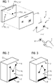
- a display DI, a touch sensor TS and a first object O1 are shown in a perspective exploded view.
- the display DI is designed as an LC display, for example, and the touch sensor TS is designed as a capacitive multi-touch sensor.
- the object O1 is shown schematically and has a first drawing P1 made of a conductive material.
- the drawing P1 has shapes K,Q,D connected by a connecting line VL.
- the drawing P1 with its connecting line VL is connected to a contact point KP.
- the contact point KP is used for touching with a human hand 1 of a user.
- the touch sensor TS registers the application of a first touch point TP1 with first touch coordinates x 1 ,y 1 .
- the first touch point TP1 is caused by the first shape D.
- the touch sensor TS registers a second touch point TP2 with the touch coordinates x 2 ,y 2 .
- the second touch point TP2 is caused by the shape Q.
- the form K generates a third touch point TP3 with the touch coordinates x 3 ,y 3 on the touch sensor TS.
- the human hand 1 touching the contact point KP serves to amplify the capacitive signal, since the natural capacitance of the human body is used.
- an identification means made of a conductive material is arranged in an object O1.
- a first drawing P1 has been rendered in conductive ink.
- the conductive ink depicts shapes K,Q,D connected by a connecting line.
- FIG 2 shows a possible embodiment of an object in a schematic three-dimensional view.
- a second object O2 is configured as a cuboid, for example, and a second drawing P2 made of conductive ink is depicted on a base area G.
- the second drawing P2 essentially has three circles which are connected to one another by the connecting line VL and the contact point KP.
- a third object O3 is shown, the third object O3 also being designed as a cuboid object with a base area G.
- the third drawing P3 applied from the conductive ink has a different information structure than that in FIG 2 illustrated second drawing P2 and can thus be used for other information or identity.
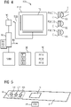
- the detection system 100 has an operator terminal HMI with a capacitive touch sensor TS.
- a first object O1, a second object O2 and a third object O3 are available to a user.
- a user can, for example, grab the first object O1 with his human hand 1 and press the base area G of the first object O1 against the touch sensor TS.
- the touch sensor TS is designed with a touch controller TC to recognize the first drawing P1 or the identification means contained therein.
- the first drawing P1 is a structure drawn in conductive ink, with particularly prominent forms K,Q,D (see FIG 1 ) on the touch sensor TS are recognized as touch points.
- the touch sensor TS can thereby have the forms K, Q, D as touch coordinates x 1 ,y 1 ,x 2 ,y 2 ,x 3 ,y 3 recognize.
- the touch sensor TS now sends touch sensor data TSD, which contain the information ID, via the touch controller TC to an evaluation unit KI.
- the evaluation unit KI can use the detected touch points TP1, TP2, TP3 or its touch coordinates x 1 , y 1 , x 2 , y 2 , x 3 , y 3 to recognize the information ID, which is in the first object O1.
- the evaluation unit KI is further developed to operate an algorithm AG, in particular with a neural network, which enables a characteristic relationship R1, R2, R3 of the detected touch points from a recognized object 01,02,03 TP1, TP2, TP3 to determine each other, making it possible that the identification means or its recognizable information ID can be recognized based on the characteristic relationship R1, R2, R3 at any point on the touch sensor TS.
- the first object O1 with the first drawing P1 represents a characteristic relationship R1
- the second object O2 with the second drawing P2 represents a second characteristic relationship R2
- the third object O3 with the third drawing P3 represents a third characteristic relationship R3 .
- a self-oriented neural map SOM can also be connected to the evaluation unit KI for the benefit of a recognition and learning method.
- the operator terminal HMI additionally has a user identification means BE in order to manage user identification and to evaluate the identification of an object 01,02,03 as an authentication of a user.
- the operator terminal HMI has a product determination means PE to manage a product determination and the recognition of the object 01,02,03 is used to determine a product P, the recognized information ID is evaluated as a product code PID.
- a conveying path F is shown as an example, on which different products P in the form of a first object O1, a second object O2 and a third object O3 are conveyed in the direction of the arrow.
- the products P are then successively out over the touch sensor TS, with the help of FIG 4 illustrated detection system 100 in the product determination mode, the product IDs PID of the individual products P or objects 01,02,03 can be recognized.
Abstract
Die Erfindung betrifft ein Verfahren zur Erkennung eines Objektes (O1,O2,O3) auf einem kapazitiven Touch-Sensor (TS) eines Bedienterminals (HMI), wobei das Objekt (O1,O2,O3) ein Identifizierungsmittel aufweist, wodurch eine erkennbare Information (ID) bereitgestellt wird, wobei mittels des Touch-Sensors (TS) das Identifizierungsmittel als Touch-Sensordaten (TSD) erkannt wird, und die Touch-Sensordaten (TSD) an eine Auswerteeinheit (KI) weitergeleitet werden, wobei in der Auswerteeinheit (KI) anhand der Touch-Sensordaten (TSD) die Information (ID) des Identifizierungsmittel ermittelt wird, wobei das Identifizierungsmittel eine aus einem leitfähigen Stoff erzeugte Zeichnung (P1,P2,P3) umfasst, und die Zeichnung (P1,P2,P3) Formen (K,Q,D) aufweist, welche durch eine Verbindungslinie (VL) verbunden sind, wobei das Objekt (O1,O2,O3) derart auf den Touch-Sensor (TS) aufgelegt wird, das die Zeichnung (P1,P2,P3) flächig auf dem Touch-Sensor (TS) aufliegt, und der Touch-Sensor (TS) dadurch die Formen (K,Q,D) als Berührpunkte (x<sub>1</sub>,y<sub>1</sub>,x<sub>2</sub>,y<sub>2</sub>,x<sub>3</sub>,y<sub>3</sub>) erkennt, wobei die Anordnung der Formen (K,Q,D) und damit die erkannten Berührpunkte (x<sub>1</sub>,y<sub>1</sub>,x<sub>2</sub>,y<sub>2</sub>,x<sub>3</sub>,y<sub>3</sub>) die Information (ID) wiedergibt.The invention relates to a method for detecting an object (O1,O2,O3) on a capacitive touch sensor (TS) of an operator terminal (HMI), the object (O1,O2,O3) having an identification means, whereby recognizable information ( ID) is provided, the means of identification being recognized as touch sensor data (TSD) by means of the touch sensor (TS), and the touch sensor data (TSD) being forwarded to an evaluation unit (KI), in which case the evaluation unit (KI) The information (ID) of the identification means is determined on the basis of the touch sensor data (TSD), the identification means comprising a drawing (P1,P2,P3) made of a conductive material, and the drawing (P1,P2,P3) forms (K ,Q,D) which are connected by a connecting line (VL), the object (O1,O2,O3) being placed on the touch sensor (TS) in such a way that the drawing (P1,P2,P3) is flat rests on the touch sensor (TS), and the touch sensor (TS) thereby the F shapes (K,Q,D) as touch points (x<sub>1</sub>,y<sub>1</sub>,x<sub>2</sub>,y<sub>2</sub> ,x<sub>3</sub>,y<sub>3</sub>), whereby the arrangement of the shapes (K,Q,D) and thus the recognized touch points (x<sub>1</sub> ,y<sub>1</sub>,x<sub>2</sub>,y<sub>2</sub>,x<sub>3</sub>,y<sub>3</sub> ) reflects the information (ID).
Description
Die Erfindung betrifft ein Verfahren zur Erkennung eines Objektes auf einem kapazitiven Touch-Sensor eines Bedienterminals, wobei das Objekt ein Identifizierungsmittel aufweist, wodurch eine erkennbare Information bereitgestellt wird, wobei mittels des Touch-Sensors das Identifizierungsmittel als Touch-Sensordaten erkannt wird, und die Touch-Sensordaten an eine Auswerteeinheit weitergeleitet werden, wobei in der Auswerteeinheit anhand der Touch-Sensordaten die Information des Identifizierungsmittels ermittelt wird.The invention relates to a method for detecting an object on a capacitive touch sensor of an operator terminal, the object having an identification means, whereby recognizable information is provided, the identification means being recognized as touch sensor data by means of the touch sensor, and the touch - Sensor data are forwarded to an evaluation unit, wherein the information of the identification means is determined in the evaluation unit based on the touch sensor data.
Auch betrifft die Erfindung ein Objekt, ausgestaltet zum Auflegen auf einen kapazitiven Touch-Sensor eines Bedienterminals umfassend, ein Identifizierungsmittel, welches ausgestaltet ist, eine für den Touch-Sensor erkennbare Information bereit zu stellen.The invention also relates to an object, designed to be placed on a capacitive touch sensor of an operating terminal, comprising an identification means, which is designed to provide information that can be recognized by the touch sensor.
Des Weiteren betrifft die Erfindung ein Erfassungssystem aufweisend ein Bedienterminal mit einem kapazitiven Touch-Sensor und einem Objekt.Furthermore, the invention relates to a detection system having an operator terminal with a capacitive touch sensor and an object.
Nach dem gebräuchlichen Fachwissen sind im Stand der Technik für eine Objekterkennung der RFID, QR-Code und Barcodes bekannt. QR-Codes und Barcodes werden beispielsweise über eine Scannerkasse gezogen, beispielsweise in Supermärkten beim Einkauf von Lebensmittel, das Einkaufs-Objekt wird mit seiner ID erkannt und kann automatisch in einer Kasse verbucht werden. Die RFID-Technik, insbesondere die NFC (Near Field Communication) hat sich heute bereits beliebter Weise als Zahlungsmethode etabliert.According to the customary expert knowledge, RFID, QR code and barcodes are known in the prior art for object recognition. For example, QR codes and barcodes are drawn over a scanner cash register, for example in supermarkets when shopping for groceries, the purchase object is recognized with its ID and can be automatically booked in a cash register. The RFID technology, in particular the NFC (Near Field Communication) has already established itself as a popular payment method.
Der Erfindung liegt die Aufgabe zugrunde, eine alternative zu den bereits bekannten Objekterkennungsverfahren und Vorrichtungen bereitzustellen.The invention is based on the object of providing an alternative to the already known object recognition methods and devices.
Die Aufgabe wird für das eingangs genannte Verfahren dadurch gelöst, dass das Identifizierungsmittel eine aus einem leitfähigen Stoff erzeugte Zeichnung umfasst, und die Zeichnung Formen aufweist, welche durch eine Verbindungslinie verbunden sind, wobei das Objekt derart auf dem Touch-Sensor aufgelegt wird, dass die Zeichnung flächig auf dem Touch-Sensor aufliegt, und der Touch-Sensor dadurch die Formen als Berührpunkte erkennt, wobei die Anordnung der Formen und dadurch die erkannten Berührpunkte die Information wiedergibt.The object is achieved for the method mentioned at the outset in that the identification means comprises a drawing made of a conductive material, and the drawing has shapes which are connected by a connecting line, with the object being placed on the touch sensor in such a way that the Drawing lies flat on the touch sensor, and the touch sensor thereby recognizes the shapes as touch points, the arrangement of the shapes and thus the detected touch points reflecting the information.
Vorzugsweise werden nun mit dem in der Zeichnung enthaltenen Formen Berührpunkte simuliert, welche normalerweise auf dem Touch-Screen durch Berühren mit dem Finger entstehen. Da die in der Zeichnung enthaltenen Formen, welche die Berührpunkte nachbilden, in einem bestimmten Verhältnis/Beziehung/Relation zu einander stehen, kann man aus diesem typischen eindeutigen Muster die Information ableiten.Contact points, which normally arise on the touch screen by touching with a finger, are preferably now simulated with the shapes contained in the drawing. Since the shapes contained in the drawing, which simulate the points of contact, are in a certain ratio/relationship/relationship to one another, information can be derived from this typical, unambiguous pattern.
Weiterhin ist es von Vorteil, wenn die Objekte jeweils einen Kontaktpunkt aufweisen, und dieser Kontaktpunkt bei dem flächigen Auflegen auf dem Touch-Sensor mit einem Teil einer menschlichen Hand eines Bedieners berührt wird. Insbesondere bei Touch-Sensoren mit einer nicht stark ausgeprägten Empfindlichkeit für Multi Touch-Erfassung, kann es hilfreich sein, wenn die Zeichnung und damit die über Verbindungslinien verbundenen Formen, welche vorzugsweise aus einer leitenden Tinte bestehen, gleichzeitig mit einer menschlichen Hand über einen Kontaktpunkt in Verbindung stehen. Die Kapazität eines menschlichen Körpers ist ausreichend um dann, selbst bei nicht so empfindlichen Touch-Screens, das Muster der Zeichnung zu erkennen.Furthermore, it is advantageous if the objects each have a contact point, and this contact point is touched with part of a human hand of an operator when they are placed flat on the touch sensor. Especially with touch sensors with a not very pronounced sensitivity for multi-touch detection, it can be helpful if the drawing and thus the shapes connected by connecting lines, which preferably consist of conductive ink, are simultaneously touched with a human hand via a contact point in connection. The capacity of a human body is sufficient to recognize the pattern of the drawing, even with touch screens that are not so sensitive.
Das Verfahren kann vorteilhafter Weise eingesetzt werden, bei einem Bedienterminal, welches eine Benutzererkennung verwaltet und die Erkennung eines Objektes als eine Authentifizierung eines Benutzers ausgewertet wird.The method can advantageously be used in an operator terminal that manages user identification and the identification of an object is evaluated as an authentication of a user.
Auch ist denkbar das Verfahren für eine Produkterkennung einzusetzen, wobei das Bedienterminal eingerichtet ist, eine Produktermittlung zu verwalten und die Erkennung des Objektes genutzt wird, ein Produkt zu ermitteln, wobei die erkannte Information als ein Produktcode ausgewertet wird.It is also conceivable to use the method for product identification, with the operator terminal being set up to manage product identification and the identification of the object being used to identify a product, with the identified information being evaluated as a product code.
In einer besonders vorteilhaften Ausgestaltung des Verfahrens ist es vorgesehen, in der Auswerteeinheit ein Algorithmus zu betreiben, welche anhand der Touch-Sensordaten die Objekterkennung lernt und erkannte Objekte abspeichert, wobei der Algorithmus derart betrieben wird, dass eine charakteristische Beziehung der Berührpunkte zueinander ermittelt wird, wodurch es möglich wird, dass Identifizierungsmittel bzw. dessen erkennbare Information anhand der charakteristischen Beziehung an einer beliebige Stelle auf den Touch-Sensor zu erkennen.In a particularly advantageous embodiment of the method, provision is made for operating an algorithm in the evaluation unit, which uses the touch sensor data to learn object recognition and stores recognized objects, the algorithm being operated in such a way that a characteristic relationship between the touch points is determined, which makes it possible to recognize the identification means or its recognizable information based on the characteristic relationship at any point on the touch sensor.
Die eingeführte künstliche Intelligenz bzw. der Algorithmus, der in der Auswerteeinheit läuft, könnte unterstützt werden mit neuronalen Netzen oder mit selbstorganisierenden Karten, welche die Muster erlernen und in der Karte abspeichern. Als selbstorganisierende Karten bezeichnet man eine Art von künstlichen neuronalen Netzen, die in der Lage sind, ein überwachtes Lernverfahren einzusetzen.The introduced artificial intelligence or the algorithm that runs in the evaluation unit could be supported with neural networks or with self-organizing maps that learn the patterns and save them in the map. Self-organizing maps are a type of artificial neural networks that are able to use a supervised learning process.
Gegenüber einem bekannten QR-Code ist es bei der verfahrensgemäßen Erfindung von besonderem Vorteil, wenn für den leitfähigen Stoff der Zeichnung eine leitfähige Tinte verwendet wird, vorzugsweise wird eine unsichtbare, leitfähige Tinte verwendet. So ist es nicht mehr möglich, wie zuvor der QR-Code einfach abzufotografieren.Compared to a known QR code, it is of particular advantage in the method according to the invention if a conductive ink is used for the conductive material of the drawing, preferably an invisible, conductive ink is used. It is no longer possible to simply photograph the QR code as before.
Des Weiteren betrifft die Erfindung ein Objekt ausgestaltet zum Auflegen auf einen kapazitiven Touch-Sensor eines Bedienterminals umfassend, ein Identifizierungsmittel, welches ausgestaltet ist, eine für den Touch-Sensor erkennbare Information bereit zu stellen, dabei weist das Identifizierungsmittel eine einen leitfähigen Stoff aufweisende Zeichnung auf, welche Formen aufweist, welche durch eine Verbindungslinie verbunden sind, wobei das Objekt zumindest eine Fläche aufweist, in welcher die Zeichnung angeordnet ist.Furthermore, the invention relates to an object designed to be placed on a capacitive touch sensor of an operator terminal, comprising an identification means which is designed to provide information recognizable for the touch sensor, the identification means having a drawing containing a conductive material , which has forms indicated by a connecting line are connected, the object having at least one face in which the drawing is located.
Bei dem Objekt ist eine Seite beispielsweise flächig ausgestaltet, so dass diese Fläche auf einem Touch-Sensor auflegbar ist, wobei dann die Zeichnung flächig auf dem Touch-Sensor aufliegt, und dadurch die Formen von dem Touch-Sensor erkannt werden können. In einer ersten Ausgestaltungsvariante kann das Objekt als eine ID-Card, Scheck-Karte oder Service-Karte ausgestaltet sein, mit welcher sich ein Benutzer an einen Bedienterminal anmelden kann oder identifizieren kann.One side of the object is, for example, flat, so that this surface can be placed on a touch sensor, in which case the drawing then lies flat on the touch sensor, and the shapes can thus be recognized by the touch sensor. In a first embodiment variant, the object can be in the form of an ID card, check card or service card, with which a user can log on to an operator terminal or be identified.
In einer zweiten Ausgestaltung kann das Objekt als ein Flyer ausgestaltet sein, die Zeichnung mit der leitenden Tinte wäre dann auf dem oder in den Flyer unsichtbar integriert und ein Flyer könnte auf den Touch-Screen gelegt werden und es gibt so über das Bedienterminal weiterführende Informationen über den Flyer.In a second embodiment, the object can be designed as a flyer, the drawing with the conductive ink would then be invisibly integrated on or in the flyer and a flyer could be placed on the touch screen and there is more information about the operator terminal the flyer.
In einer dritten Ausgestaltungsvariante kann das Objekt in einer Umverpackung eines Produktes integriert sein und so über ein Kassensystem mit einem Touch-Sensor registriert werden.In a third embodiment variant, the object can be integrated into an outer packaging of a product and can thus be registered via a cash register system with a touch sensor.
Um die Empfindlichkeit bei dem Objekt für eine Registrierung auf dem Touch-Sensor zu erhöhen, ist ein Objekt mit einem Kontaktpunkt ausgestaltet, und dieser Kontaktpunkt ist ausgestaltet, von einer menschlichen Hand eines Bedieners berührt zu werden. Dies bietet den Vorteil, dass eine Kapazität eines menschlichen Körpers, welche beispielsweise im Bereich von 100 pF bis 300 pF liegt, ausgenutzt werden kann.In order to increase the sensitivity of the object for registration on the touch sensor, an object is designed with a contact point, and this contact point is designed to be touched by an operator's human hand. This offers the advantage that a capacitance of a human body, which is in the range from 100 pF to 300 pF, for example, can be utilized.
Auch betrifft die Erfindung ein Erfassungssystem aufweisend ein Bedienterminal mit einem kapazitiven Touch-Sensor, wobei ein Objekt zum Auflegen auf dem Touch-Sensor zur Erkennung genutzt wird. Dabei ist das Objekt zum Auflegen auf den Touch-Sensor ausgestaltet und es weist ein zusätzliches Identifizierungsmittel auf, welches wiederum ausgestaltet ist, eine für den Touch-Sensor erkennbare Information bereitzustellen, dabei weist das Identifizierungsmittel eine einen leitfähigen Stoff aufweisende Zeichnung auf, welche Formen aufweist, welche durch eine Verbindungslinie verbunden sind, wobei das Objekt zumindest eine Fläche aufweist, in welcher die Zeichnung angeordnet ist. Dabei ist der Touch-Sensor weiterhin dazu ausgestaltet, das Identifizierungsmittel als Touch-Sensordaten zu ermitteln, wenn das Objekt auf den Touch-Sensor aufgelegt wird und die Zeichnung flächig auf dem Touch-Sensor aufliegt, und der Touch-Sensor dadurch die Formen als Berührpunkte erkennt, weiterhin ist eine Auswerteeinheit vorhanden, welche anhand der Touch-Sensordaten, die Informationen ermittelt, wobei die Auswerteeinheit anhand der erkannten Berührpunkte die Informationen ermittelt.The invention also relates to a detection system having an operator terminal with a capacitive touch sensor, with an object being used to be placed on the touch sensor for detection. The object is designed to be placed on the touch sensor and has an additional means of identification, which in turn is designed to provide information recognizable for the touch sensor, the identification means having a drawing which has a conductive substance and which has shapes which are connected by a connecting line, the object having at least one area in which the drawing is arranged. The touch sensor is also designed to determine the means of identification as touch sensor data when the object is placed on the touch sensor and the drawing lies flat on the touch sensor, and the touch sensor uses the shapes as touch points recognizes, there is also an evaluation unit which uses the touch sensor data to determine the information, with the evaluation unit determining the information using the recognized touch points.
In einer weiterführenden Ausgestaltung ist das Erfassungssystem dahingehend erweitert, dass die Objekte jeweils einen Kontaktpunkt aufweisen, und dieser Kontaktpunkt bei dem flächigen Auflegen auf dem Touch-Sensor mit einem Teil einer menschlichen Hand eines Bedieners berührt wird.In a further refinement, the detection system is expanded such that the objects each have a contact point, and this contact point is touched with part of an operator's human hand when they are placed flat on the touch sensor.
Im Hinblick auf eine Benutzeridentifizierung für eine industrielle Anlage, ist das Erfassungssystem mit Vorteil dazu ausgestaltet, dass das Bedienterminal ein Benutzererkennungs-Mittel aufweist, um eine Benutzererkennung zu verwalten und die Erkennung eines Objektes als eine Authentifizierung eines Benutzers auszuwerten.With regard to user identification for an industrial plant, the detection system is advantageously designed such that the operator terminal has a user identification means in order to manage user identification and to evaluate the identification of an object as an authentication of a user.
Im Hinblick auf ein zukünftiges Kassensystem oder auf eine Produktermittlung in einer Fertigung ist das Erfassungssystem vorteilhafter Weise dazu ausgestaltet, dass das Bedienterminal ein Produktermittlungs-Mittel aufweist, um eine Produktermittlung zu verwalten und die Erkennung des Objektes genutzt wird, ein Produkt zu ermitteln, wobei die erkannte Information als ein Produktcode ausgewertet wird.With regard to a future checkout system or product identification in a production facility, the detection system is advantageously configured such that the operating terminal has product identification means to manage product identification and the identification of the object is used to identify a product, with the recognized information is evaluated as a product code.
In einer weiteren Ausgestaltung weist das Erfassungssystem ein Algorithmus auf, welcher in der Auswerteeinheit betrieben wird, dieser Algorithmus wird anhand der Touch-Sensordaten die Objekterkennung erlernen und erkannte Objekte abspeichern, wobei der Algorithmus derart betrieben wird, dass eine charakteristische Beziehung der Berührpunkte zueinander ermittelt wird, wodurch es möglich wird, das Identifizierungsmittel bzw. dessen erkennbare Information anhand der charakteristischen Beziehung an einer beliebigen Stelle auf dem Touch-Sensor zu erkennen.In a further refinement, the detection system has an algorithm which is operated in the evaluation unit this algorithm will learn object recognition based on the touch sensor data and will store recognized objects, with the algorithm being operated in such a way that a characteristic relationship between the touch points is determined, which makes it possible to identify the identification means or its recognizable information based on the characteristic relationship can be seen anywhere on the touch sensor.
Die Zeichnung zeigt ein Ausführungsbeispiel der Erfindung, dabei zeigt die
- FIG 1
- das Ausführungsprinzip mit einem Objekt aus leitender Tinte,
- FIG 2
- eine Ausgestaltungsvariante eines weiteren Objektes mit leitender Tinte,
- FIG 3
- noch eine weitere Ausgestaltung eines Objektes,
- FIG 4
- ein Erfassungssystem mit einem Bedienterminal und
- FIG 5
- ein in einem Transportweg eingelassener Touch-Screen.
- FIG 1
- the principle of execution with an object made of conductive ink,
- FIG 2
- a design variant of another object with conductive ink,
- 3
- yet another configuration of an object,
- FIG 4
- a recording system with an operator terminal and
- 5
- a touch screen embedded in a transport path.
Gemäß
Der Touch-Sensor TS registriert ein Auflegen eines ersten Berührpunktes TP1 mit ersten Berührkoordinaten x1,y1. Der erste Berührpunkt TP1 wird durch die erste Form D hervorgerufen. Weiterhin registriert der Touch-Sensor TS einen zweiten Berührpunkt TP2 mit den Berührkoordinaten x2,y2. Der zweite Berührpunkt TP2 wird durch die Form Q hervorgerufen. Die Form K erzeugt auf dem Touch-Sensor TS einen dritten Berührpunkt TP3 mit den Berührkoordinaten x3,y3.The touch sensor TS registers the application of a first touch point TP1 with first touch coordinates x 1 ,y 1 . The first touch point TP1 is caused by the first shape D. Furthermore, the touch sensor TS registers a second touch point TP2 with the touch coordinates x 2 ,y 2 . The second touch point TP2 is caused by the shape Q. The form K generates a third touch point TP3 with the touch coordinates x 3 ,y 3 on the touch sensor TS.
Die Berührung der menschlichen Hand 1 des Kontaktpunkt KP dient der Verstärkung des kapazitiven Signals, da die natürliche Kapazität des menschlichen Körpers ausgenutzt wird.The human hand 1 touching the contact point KP serves to amplify the capacitive signal, since the natural capacitance of the human body is used.
Erfindungsgemäß wird das Prinzip ausgenutzt, dass in einem Objekt O1 ein Identifizierungsmittel aus einem leitfähigen Stoff angeordnet ist. In diesem Fall ist eine erste Zeichnung P1 aus einer leitfähigen Tinte dargestellt worden. Die leitfähige Tinte bildet Formen K,Q,D ab, welche durch eine Verbindungslinie verbunden sind. Wird das erste Objekt O1 flächig auf den Touch-Sensor TS aufgelegt, können damit von dem Touch-Sensor TS Berührpunkte TP1,TP2,TP3 erkannt werden, wobei die Koordinaten x1, y1;x2, y2;x3, y3 der Berührpunkte TP1,TP2,TP3 die Information ID des Objektes O1 wiedergibt.According to the invention, use is made of the principle that an identification means made of a conductive material is arranged in an object O1. In this case, a first drawing P1 has been rendered in conductive ink. The conductive ink depicts shapes K,Q,D connected by a connecting line. If the first object O1 is laid flat on the touch sensor TS, contact points TP1, TP2, TP3 can be detected by the touch sensor TS, with the coordinates x 1 , y 1 ; x 2 , y 2 ; x 3 , y 3 of the touch points TP1, TP2, TP3 reproduces the information ID of the object O1.
Da sich die Berührpunkte TP1,TP2,TP3 in einen bestimmten Verhältnis/Beziehung oder Relation zueinander befinden, kann diese eindeutige Relation dazu genutzt werden, die Information auch an beliebigen Stellen auf dem Touch-Screen TS wieder zu erkennen.Since the touch points TP1, TP2, TP3 are in a specific ratio/relationship or relationship to one another, this unique relationship can be used to recognize the information again at any point on the touch screen TS.
Die
Gemäß
Gemäß der
Die Auswerteeinheit KI ist dahin weitergebildet, insbesondere mit einem neuronalen Netz, einen Algorithmus AG zu betreiben, welcher es ermöglicht, von einem erkannten Objekt 01,02,03 eine charakteristische Beziehung R1,R2,R3 der erfassten Berührpunkte TP1,TP2,TP3 zueinander zu ermitteln, wodurch es möglich wird, dass das Identifizierungsmittel bzw. dessen erkennbare Information ID anhand der charakteristischen Beziehung R1,R2,R3 an einer beliebigen Stelle auf dem Touch-Sensor TS zu erkennen ist.The evaluation unit KI is further developed to operate an algorithm AG, in particular with a neural network, which enables a characteristic relationship R1, R2, R3 of the detected touch points from a recognized
Demnach gibt das erste Objekt O1 mit der ersten Zeichnung P1 eine charakteristische Beziehung R1 wieder, das zweite Objekt O2 mit der zweiten Zeichnung P2 gibt eine zweite charakteristische Beziehung R2 wieder und das dritte Objekt O3 mit der dritten Zeichnung P3 gibt eine dritte charakteristische Beziehung R3 wieder. An die Auswerteeinheit KI kann zugunsten eines Erkennungs- und Lernverfahrens weiterhin eine selbstorientierte neuronale Karte SOM angeschaltet sein.Accordingly, the first object O1 with the first drawing P1 represents a characteristic relationship R1, the second object O2 with the second drawing P2 represents a second characteristic relationship R2 and the third object O3 with the third drawing P3 represents a third characteristic relationship R3 . A self-oriented neural map SOM can also be connected to the evaluation unit KI for the benefit of a recognition and learning method.
Wir das Erfassungssystem 100 für eine Benutzererkennung genutzt, so weist das Bedienterminal HMI zusätzlich ein Benutzererkennungs-Mittel BE auf, um eine Benutzererkennung zu verwalten und die Erkennung eines Objektes 01,02,03 als eine Authentifizierung eines Benutzers auszuwerten.If the
Wird das Erfassungssystem 100 für eine Produktermittlung genutzt, so weist das Bedienterminal HMI ein Produktermittlungs-Mittel PE auf, um eine Produktermittlung zu verwalten und die Erkennung des Objektes 01,02,03 wird genutzt, ein Produkt P zu ermitteln, wobei die erkannte Information ID als ein Produkt-Code PID ausgewertet wird.If the
Gemäß
Weitere die Erfindung betreffende Gedanken sind folgende:
Mit einem Muster mit transparenter leitfähiger Tinte ist es möglich, ein einzigartiges Muster mit künstlichen neuronalen Netzwerken zu identifizieren, indem man es gleichzeitig mit der Hand gegen einen Multitouch-Bildschirm drückt. Die Kapazität des menschlichen Körpers kann zusätzlich genutzt werden. Durch die Möglichkeit, einzigartige Muster zu erkennen, öffnet diese Erfindung die Tür zu neuen Möglichkeiten, Objekte zuverlässiger, effektiver und billiger zu identifizieren als herkömmliche Systeme wie RFID, QR-Code und Barcodes.Other ideas relating to the invention are as follows:
With a transparent conductive ink pattern, it is possible to identify a unique pattern with artificial neural networks by simultaneously pressing it with your hand against a multi-touch screen. The capacity of the human body can be additionally used. By being able to recognize unique patterns, this invention opens the door to new ways of identifying objects more reliably, effectively and cheaply than traditional systems such as RFID, QR code and barcodes.
Um ein zuverlässiges Erkennen eines Musters zu realisieren, ist es erforderlich, den Benutzern zu ermöglichen, ein leitfähiges Muster frei zu scannen, ohne dass sie das leitfähige Farbkreismuster in einer bestimmten x- und y-Koordinate des Multitouch-Bildschirms lokalisieren müssen. Dazu kann die Verwendung eines künstlichen Neuronalen Netzwerks verwendet werden, um die Erkennung mehrerer Muster in jeder x- und y-Koordinate zu ermöglichen.In order to realize reliable pattern recognition, it is necessary to allow users to freely scan a conductive pattern without having to locate the color circle conductive pattern in a specific x and y coordinate of the multi-touch screen. This can be done using an artificial neural network to enable the recognition of multiple patterns in each x and y coordinate.
Es gibt viele Anwendungsfälle, die mit dieser Erfindung erreicht werden können. Bei den Anwendungsfällen ist zu beachten, dass die leitfähige Tinte beispielsweise an Kartons, ID-Karten, Produktheften usw. haftet bzw. aufgedruckt ist.
- a) Produktionsartikelverfolgung. Der Benutzer scannt einen Artikel (z.B. Werksartikel, Amazon-Lieferbox, Medizinbox, Buch, etc.) und das System ist in der Lage, die Beschreibung des spezifischen Artikels zu finden, z. B. wo und wann es hergestellt wurde. Dieser Anwendungsfall ist auch für Artikelerfassungen und Datenvervollständigungen praktisch. Wenn beispielsweise eine Lieferbox eines Geräts gescannt wird, zeigt das System seine Seriennummer, Hardware-Spezifikation und Firmware-Version sowie die Bedienungsanleitung an.
- b) Authentifizierung. Durch scannen einer ID-Karte kann der Benutzer auf seine Daten zugreifen und erhält seine relevanten Informationen, wie die nächsten Aufgaben, Produktionslinienergebnisse usw. sind.
- c) Digitaler Zugriff. Das System kann eine bestimmte Website wie ein Benutzerhandbuch PDF, Kontaktinformationsseite, Feedback-Formular, Kartenstandort, etc. öffnen, indem es einen Artikel wie ein Produktheft, einen Flyer, eine Visitenkarte scannt. Wenn ein Gerät über GPS oder andere Sensoren verfügt, können diese verwendet werden, um die Benutzererfahrung zu verbessern, z. B. kann ein mobiles Gerät die Karten-App mit der Route zu einem Wunschplatz öffnen.
- d) Personalisierte Kartenanfrage. Bestimmte Karten mit programmierten Aktionen können verwendet werden, die ein bestimmtes Ziel haben, z. B. durch Scannen einer Support-Karte, das System weiß, wer und wo ein Benutzer eine Karte gescannt hat, und kann den Verantwortlichen für diese spezifische Betriebslinie benachrichtigen.
- a) Production item tracking. The user scans an item (e.g. factory item, amazon delivery box, medicine box, book, etc.) and the system is able to find the description of the specific item, e.g. B. Where and when it was made. This use case is also useful for item registration and data completion. For example, when a device delivery box is scanned, the system displays its serial number, hardware specification and firmware version, as well as the user manual.
- b) authentication. By scanning an ID card, the user can access their data and get their relevant ones Information like next tasks, production line results etc.
- c) Digital Access. The system can open a specific website like a user manual PDF, contact information page, feedback form, map location, etc. by scanning an item like a product booklet, flyer, business card. If a device has GPS or other sensors, these can be used to improve the user experience, e.g. B. a mobile device can open the map app with the route to a desired place.
- d) Personalized card request. Certain cards with programmed actions can be used that have a specific goal, e.g. B. by scanning a support card, the system knows who and where a user scanned a card and can notify the person responsible for that specific line of operation.
Vorteile:
- Normalerweise hat eine Fabrik Displays, aber keine Tastaturen oder Zeigergeräte. Für diese Erfindung ist keines von ihnen erforderlich, was die Interaktion mit dem System schneller macht.
- Mit der Verwendung anderer Sensoren wie GPS, die in mobilen Geräten enthalten sind, kann ein Benutzer Zeit sparen, indem er Routen zu bestimmten Zielen findet.
- Reduzieren der Zeit für manuelle Eingaben von Informationen in das System. Diese Erfindung kann gleichzeitig Aktionen auslösen und Abfragedaten auslösen, die einem einzelnen Muster zugeordnet sind.
- Reduzieren der Zeit der manuellen Suche nach Systemdaten, wie z. B. Öffnen einer App, Login/Logout, Start/Stopp einer Laufzeit.
- Die Daten werden sofort auf demselben Bildschirm angezeigt, auf dem ein gescannter Vorgang stattgefunden hat, wodurch die Betriebszeit verkürzt wird, auch dies verbessert die Benutzererfahrung nach dem WYSIWYG-Prinzip (What You See Is What You Get).
- Es ist keine zusätzliche Hardware erforderlich, da jedes Multitouch-Display verwendet werden kann, einschließlich alter Industriedisplays, mobiler Geräte oder Tablets.
- Die Kosten für dieses System sind geringer als bei RFID-Sensoren und -Tags, da kein zusätzlicher Sensor und Tags erforderlich sind.
- Die Kosten für das hier vorgestellte leitfähige Tintensystem sind auch geringer als bei QR-Codes, da keine Kamera benötigt wird.
- Das System kann mit Web-Technologien (JavaScript) implementiert werden, die in jedem Webbrowser ausgeführt werden. Dies macht die Implementierung plattformübergreifend.
- Die leitfähigen Muster können mit herkömmlichen Druckern gedruckt werden, sodass jeder Wunsch intuitiv und schnell integriert werden kann.
- Diese Erfindung ermöglicht es, Aktionen wie Benachrichtigung anderer Systeme, Start/Stopp-Maschinen, Start/Stopp einer Laufzeit, Erhöhung/Abnahme der Tag-Werte von Sensoren, Anrufe, etc. auszulösen.
- Mit einer transparenten leitfähigen Tinte können die Schaltungsmuster auf Oberflächen platziert werden, ohne sonstige Darstellungen zu beeinflussen.
- Normally a factory has displays but no keyboards or pointing devices. None of them are required for this invention, which makes interacting with the system faster.
- With the use of other sensors such as GPS included in mobile devices, a user can save time by finding routes to specific destinations.
- Reducing the time it takes to manually enter information into the system. This invention can simultaneously trigger actions and trigger query data associated with a single pattern.
- Reducing the time spent manually searching for system information, such as B. Opening an app, login/logout, start/stop of a runtime.
- The data is instantly displayed on the same screen where a scanned operation took place, reducing uptime, also improving the WYSIWYG (What You See Is What You Get) user experience.
- No additional hardware is required as any multi-touch display can be used, including legacy industrial displays, mobile devices or tablets.
- The cost of this system is lower than RFID sensors and tags because no additional sensor and tags are required.
- The cost of the conductive ink system presented here is also lower than QR codes because no camera is required.
- The system can be implemented using web technologies (JavaScript) running in any web browser. This makes the implementation cross-platform.
- The conductive patterns can be printed with conventional printers, so that every wish can be integrated intuitively and quickly.
- This invention makes it possible to trigger actions such as notification of other systems, start/stop machines, start/stop a runtime, increase/decrease tag values of sensors, calls, etc.
- With a transparent conductive ink, the circuit patterns can be placed on surfaces without affecting other renderings.
Sicherheit:
- Das Zusammenspiel einer Person ist erforderlich, damit diese Erfindung funktioniert.
- Ein QR-Code-System kann einfach fotografiert und über das Internet geteilt werden, um für jedermann zugänglich zu sein. Mit dieser Erfindung gibt es keine Möglichkeit, dies zu tun.
- Ein RFID-System kann ohne Zustimmung einer Person ausgelöst werden. Mit dieser Erfindung ist dies nicht möglich.
- Um eine Replikation der Muster zu vermeiden, ist eine transparente leitfähige Tinte vorgesehen.
- One person's interaction is required for this invention to work.
- A QR code system can be easily photographed and shared over the internet to be accessible to everyone. With this invention there is no way to do that.
- An RFID system can be triggered without the consent of a person. This is not possible with this invention.
- A transparent conductive ink is provided to avoid replication of the patterns.
Claims (13)
dadurch gekennzeichnet, dass das Identifizierungsmittel eine aus einem leitfähigen Stoff erzeugte Zeichnung (P1,P2,P3) umfasst, und die Zeichnung (P1,P2,P3) Formen (K,Q,D) aufweist, welche durch eine Verbindungslinie (VL) verbunden sind, wobei das Objekt (01,02,03) derart auf den Touch-Sensor (TS) aufgelegt wird, das die Zeichnung (P1,P2,P3) flächig auf dem Touch-Sensor (TS) aufliegt, und der Touch-Sensor (TS) dadurch die Formen (K,Q,D) als Berührpunkte (x1,y1,x2,y2,x3,y3) erkennt, wobei die Anordnung der Formen (K,Q,D) und damit die erkannten Berührpunkte (x1,y1,x2,y2,x3,y3) die Information (ID) wiedergibt.Method for detecting an object (01,02,03) on a capacitive touch sensor (TS) of an operator terminal (HMI), the object (O1,O2,O3) having an identification means, whereby recognizable information (ID) is provided , The identification means being recognized as touch sensor data (TSD) by means of the touch sensor (TS), and the touch sensor data (TSD) being forwarded to an evaluation unit (KI), with the evaluation unit (KI) using the touch Sensor data (TSD) the information (ID) of the identification means is determined,
characterized in that the identification means comprises a drawing (P1,P2,P3) made of a conductive substance, and the drawing (P1,P2,P3) has shapes (K,Q,D) connected by a connecting line (VL). are, the object (01,02,03) being placed on the touch sensor (TS) in such a way that the drawing (P1,P2,P3) lies flat on the touch sensor (TS), and the touch sensor (TS) thereby recognizes the shapes (K,Q,D) as points of contact (x 1 ,y 1 ,x 2 ,y 2 ,x 3 ,y 3 ), the arrangement of the shapes (K,Q,D) and thus the detected touch points (x 1 ,y 1 ,x 2 ,y 2 ,x 3 ,y 3 ) reproduces the information (ID).
ein Identifizierungsmittel, welches ausgestaltet ist, eine für den Touch-Sensor (TS) erkennbare Information (ID) bereitzustellen,
dadurch gekennzeichnet, dass das Identifizierungsmittel eine einen leitfähigen Stoff aufweisende Zeichnung (P1,P2,P3) umfasst, welche Formen (K,Q,D) aufweist, welche durch eine Verbindungslinie (VL) verbunden sind, wobei das Objekt (O1,O2,O3) zumindest eine Fläche (G) aufweist, in welcher die Zeichnung(P1,P2,P3) angeordnet ist.Object (01,02,03) designed to be placed on a capacitive touch sensor (TS) of an operator terminal (HMI) comprising,
an identification means which is designed to provide information (ID) recognizable for the touch sensor (TS),
characterized in that the identification means comprises a drawing (P1,P2,P3) comprising a conductive substance, having shapes (K,Q,D) connected by a connecting line (VL), the object (O1,O2, O3) has at least one area (G) in which the drawing (P1, P2, P3) is arranged.
Priority Applications (5)
| Application Number | Priority Date | Filing Date | Title |
|---|---|---|---|
| EP21155252.6A EP4040331A1 (en) | 2021-02-04 | 2021-02-04 | Method for detecting an object on a capacitive touch sensor, object and detection system |
| CN202180092961.8A CN116802642A (en) | 2021-02-04 | 2021-12-17 | Method for detecting an object on a capacitive touch sensor, object and detection system |
| US18/275,461 US20240104314A1 (en) | 2021-02-04 | 2021-12-17 | Object, Detection System and Method for Detecting an Object on a Capacitive Tough Sensor |
| EP21840006.7A EP4232942A1 (en) | 2021-02-04 | 2021-12-17 | Method for detecting an object on a capacitive touch sensor, object, and detection system |
| PCT/EP2021/086573 WO2022167139A1 (en) | 2021-02-04 | 2021-12-17 | Method for detecting an object on a capacitive touch sensor, object, and detection system |
Applications Claiming Priority (1)
| Application Number | Priority Date | Filing Date | Title |
|---|---|---|---|
| EP21155252.6A EP4040331A1 (en) | 2021-02-04 | 2021-02-04 | Method for detecting an object on a capacitive touch sensor, object and detection system |
Publications (1)
| Publication Number | Publication Date |
|---|---|
| EP4040331A1 true EP4040331A1 (en) | 2022-08-10 |
Family
ID=74553681
Family Applications (2)
| Application Number | Title | Priority Date | Filing Date |
|---|---|---|---|
| EP21155252.6A Withdrawn EP4040331A1 (en) | 2021-02-04 | 2021-02-04 | Method for detecting an object on a capacitive touch sensor, object and detection system |
| EP21840006.7A Pending EP4232942A1 (en) | 2021-02-04 | 2021-12-17 | Method for detecting an object on a capacitive touch sensor, object, and detection system |
Family Applications After (1)
| Application Number | Title | Priority Date | Filing Date |
|---|---|---|---|
| EP21840006.7A Pending EP4232942A1 (en) | 2021-02-04 | 2021-12-17 | Method for detecting an object on a capacitive touch sensor, object, and detection system |
Country Status (4)
| Country | Link |
|---|---|
| US (1) | US20240104314A1 (en) |
| EP (2) | EP4040331A1 (en) |
| CN (1) | CN116802642A (en) |
| WO (1) | WO2022167139A1 (en) |
Citations (2)
| Publication number | Priority date | Publication date | Assignee | Title |
|---|---|---|---|---|
| EP2722789A2 (en) * | 2012-10-17 | 2014-04-23 | Giesecke & Devrient GmbH | Method for verifying the authenticity of a portable data carrier |
| EP2635996B1 (en) * | 2010-09-20 | 2017-11-08 | T-Touch International S.à.r.l. | Information carrier and system for acquiring information |
-
2021
- 2021-02-04 EP EP21155252.6A patent/EP4040331A1/en not_active Withdrawn
- 2021-12-17 US US18/275,461 patent/US20240104314A1/en active Pending
- 2021-12-17 EP EP21840006.7A patent/EP4232942A1/en active Pending
- 2021-12-17 CN CN202180092961.8A patent/CN116802642A/en active Pending
- 2021-12-17 WO PCT/EP2021/086573 patent/WO2022167139A1/en active Application Filing
Patent Citations (2)
| Publication number | Priority date | Publication date | Assignee | Title |
|---|---|---|---|---|
| EP2635996B1 (en) * | 2010-09-20 | 2017-11-08 | T-Touch International S.à.r.l. | Information carrier and system for acquiring information |
| EP2722789A2 (en) * | 2012-10-17 | 2014-04-23 | Giesecke & Devrient GmbH | Method for verifying the authenticity of a portable data carrier |
Also Published As
| Publication number | Publication date |
|---|---|
| US20240104314A1 (en) | 2024-03-28 |
| EP4232942A1 (en) | 2023-08-30 |
| WO2022167139A1 (en) | 2022-08-11 |
| CN116802642A (en) | 2023-09-22 |
Similar Documents
| Publication | Publication Date | Title |
|---|---|---|
| EP2635996B1 (en) | Information carrier and system for acquiring information | |
| CN106155298B (en) | The acquisition method and device of man-machine recognition methods and device, behavioural characteristic data | |
| DE102015122849B4 (en) | Method of operating a mobile electronic device, mobile electronic device and a machine-readable medium using the same | |
| DE112015003933T5 (en) | Apparatus and method for performing a things selection process | |
| DE102018120510A1 (en) | PURCHASER IDENTIFICATION SYSTEMS AND METHODS FOR IDENTIFYING NEW RADIO FREQUENCY IDENTIFICATION (RFID) IDEAS EVENTS NEAR AN RFID READER | |
| EP2523080A1 (en) | System for localising and identifying at least two separate objects | |
| CN202230490U (en) | Bar code scanning contrasting error proof system | |
| EP4040331A1 (en) | Method for detecting an object on a capacitive touch sensor, object and detection system | |
| EP2015263A1 (en) | Goods selection unit | |
| CN106126098A (en) | A kind of can the writing signing method and system of Information locating | |
| EP2418607A1 (en) | Capacitive data carrier and system for recording information | |
| CH710554A1 (en) | A process for the decentralized control of machine tools. | |
| KR102049299B1 (en) | Kiosk apparatus for event process | |
| Dewhurst et al. | Empirical investigation of biometric, non-visible, intra-signature features in known and simulated signatures | |
| DE102012011103B4 (en) | A method for handling access or usage permissions and handling system for handling access or usage permissions | |
| DE112021001432T5 (en) | INTELLIGENT SHELVING SYSTEMS AND METHODS TO OPERATE THEM | |
| JP6502031B2 (en) | INFORMATION PROCESSING APPARATUS, INFORMATION PROCESSING METHOD, AND PROGRAM | |
| JP6450558B2 (en) | Time recorder, information processing method, program, and attendance / exit management system. | |
| CN103870793B (en) | The monitoring method and device of paper media's advertisement | |
| Agarwal et al. | Student attendance system based on the face recognition | |
| DE102014201136A1 (en) | Intelligent tablet and method and system for determining usage data of a smart tablet | |
| DE102012217638A1 (en) | Interactive blackboard and home control system | |
| EP2654010A1 (en) | System for displaying information visually and for data communication | |
| EP1921566A1 (en) | Assembly for processing radiopaque images | |
| DE102021212014B4 (en) | Method and device for detecting moving equipment |
Legal Events
| Date | Code | Title | Description |
|---|---|---|---|
| PUAI | Public reference made under article 153(3) epc to a published international application that has entered the european phase |
Free format text: ORIGINAL CODE: 0009012 |
|
| STAA | Information on the status of an ep patent application or granted ep patent |
Free format text: STATUS: THE APPLICATION HAS BEEN PUBLISHED |
|
| AK | Designated contracting states |
Kind code of ref document: A1 Designated state(s): AL AT BE BG CH CY CZ DE DK EE ES FI FR GB GR HR HU IE IS IT LI LT LU LV MC MK MT NL NO PL PT RO RS SE SI SK SM TR |
|
| STAA | Information on the status of an ep patent application or granted ep patent |
Free format text: STATUS: THE APPLICATION IS DEEMED TO BE WITHDRAWN |
|
| 18D | Application deemed to be withdrawn |
Effective date: 20230211 |