EP4040065A1 - Control system - Google Patents
Control system Download PDFInfo
- Publication number
- EP4040065A1 EP4040065A1 EP20872564.8A EP20872564A EP4040065A1 EP 4040065 A1 EP4040065 A1 EP 4040065A1 EP 20872564 A EP20872564 A EP 20872564A EP 4040065 A1 EP4040065 A1 EP 4040065A1
- Authority
- EP
- European Patent Office
- Prior art keywords
- target area
- air conditioning
- conditioning target
- control system
- air conditioner
- Prior art date
- Legal status (The legal status is an assumption and is not a legal conclusion. Google has not performed a legal analysis and makes no representation as to the accuracy of the status listed.)
- Granted
Links
Images




Classifications
-
- F—MECHANICAL ENGINEERING; LIGHTING; HEATING; WEAPONS; BLASTING
- F24—HEATING; RANGES; VENTILATING
- F24F—AIR-CONDITIONING; AIR-HUMIDIFICATION; VENTILATION; USE OF AIR CURRENTS FOR SCREENING
- F24F11/00—Control or safety arrangements
- F24F11/30—Control or safety arrangements for purposes related to the operation of the system, e.g. for safety or monitoring
- F24F11/46—Improving electric energy efficiency or saving
-
- F—MECHANICAL ENGINEERING; LIGHTING; HEATING; WEAPONS; BLASTING
- F24—HEATING; RANGES; VENTILATING
- F24F—AIR-CONDITIONING; AIR-HUMIDIFICATION; VENTILATION; USE OF AIR CURRENTS FOR SCREENING
- F24F11/00—Control or safety arrangements
- F24F11/50—Control or safety arrangements characterised by user interfaces or communication
-
- F—MECHANICAL ENGINEERING; LIGHTING; HEATING; WEAPONS; BLASTING
- F24—HEATING; RANGES; VENTILATING
- F24F—AIR-CONDITIONING; AIR-HUMIDIFICATION; VENTILATION; USE OF AIR CURRENTS FOR SCREENING
- F24F11/00—Control or safety arrangements
- F24F11/50—Control or safety arrangements characterised by user interfaces or communication
- F24F11/56—Remote control
-
- G—PHYSICS
- G06—COMPUTING OR CALCULATING; COUNTING
- G06F—ELECTRIC DIGITAL DATA PROCESSING
- G06F3/00—Input arrangements for transferring data to be processed into a form capable of being handled by the computer; Output arrangements for transferring data from processing unit to output unit, e.g. interface arrangements
- G06F3/01—Input arrangements or combined input and output arrangements for interaction between user and computer
-
- G—PHYSICS
- G06—COMPUTING OR CALCULATING; COUNTING
- G06F—ELECTRIC DIGITAL DATA PROCESSING
- G06F3/00—Input arrangements for transferring data to be processed into a form capable of being handled by the computer; Output arrangements for transferring data from processing unit to output unit, e.g. interface arrangements
- G06F3/01—Input arrangements or combined input and output arrangements for interaction between user and computer
- G06F3/011—Arrangements for interaction with the human body, e.g. for user immersion in virtual reality
-
- H—ELECTRICITY
- H04—ELECTRIC COMMUNICATION TECHNIQUE
- H04L—TRANSMISSION OF DIGITAL INFORMATION, e.g. TELEGRAPHIC COMMUNICATION
- H04L12/00—Data switching networks
- H04L12/28—Data switching networks characterised by path configuration, e.g. LAN [Local Area Networks] or WAN [Wide Area Networks]
- H04L12/2803—Home automation networks
-
- H—ELECTRICITY
- H04—ELECTRIC COMMUNICATION TECHNIQUE
- H04M—TELEPHONIC COMMUNICATION
- H04M1/00—Substation equipment, e.g. for use by subscribers
-
- F—MECHANICAL ENGINEERING; LIGHTING; HEATING; WEAPONS; BLASTING
- F24—HEATING; RANGES; VENTILATING
- F24F—AIR-CONDITIONING; AIR-HUMIDIFICATION; VENTILATION; USE OF AIR CURRENTS FOR SCREENING
- F24F2120/00—Control inputs relating to users or occupants
- F24F2120/10—Occupancy
- F24F2120/12—Position of occupants
-
- F—MECHANICAL ENGINEERING; LIGHTING; HEATING; WEAPONS; BLASTING
- F24—HEATING; RANGES; VENTILATING
- F24F—AIR-CONDITIONING; AIR-HUMIDIFICATION; VENTILATION; USE OF AIR CURRENTS FOR SCREENING
- F24F2120/00—Control inputs relating to users or occupants
- F24F2120/20—Feedback from users
Definitions
- the present invention relates to a control system.
- Patent Literature 1 Japanese Unexamined Patent Publication No. JP 2017-150702 A
- a control system is a control system that controls an air conditioner that air-conditions an air conditioning target area using a detection value of a biometric sensor worn by a user.
- the control system includes a first acquisition part, a first determination part, and a second determination part.
- the first acquisition part acquires first information related to a distance between a reference point of an air conditioning target area and the biometric sensor.
- the first determination part determines whether to use the detection value of the biometric sensor for controlling the air conditioner based on the first information and a determination criterion.
- the second determination part determines the determination criterion.
- the air-conditioning control can be more appropriately performed when the detection value of the biometric sensor worn by the user is used for controlling the air conditioner.
- a control system is the system according to the first aspect, in which the first determination part determines whether the biometric sensor is located in the air conditioning target area based on the first information and the determination criterion.
- the detection value of the biometric sensor can be used for controlling the air conditioner.
- a control system is the system according to the first or second aspect, in which the first acquisition part acquires radio wave intensity between the air conditioner and the biometric sensor as the first information.
- the radio wave intensity can be used for determining whether to use the detection value of the biometric sensor for controlling the air conditioner.
- a control system is the system according to the first or second aspect, in which the first acquisition part acquires the position of the reference point of the air conditioning target area and the position of the biometric sensor, respectively and thereby acquires the distance information between the reference point of the air conditioning target area and the biometric sensor as the first information.
- position information can be used for determining whether to use the detection value of the biometric sensor for controlling the air conditioner.
- a control system is the system according to the first aspect and further includes a second acquisition part that acquires manually input information.
- the manually input information includes at least one of the information related to a size of the air conditioning target area or the information related to the distance from the reference point of the air conditioning target area, and the second determination part determines the determination criterion based on the information from the second acquisition part.
- initial setting of control of the air conditioner can be performed by manually inputting information.
- a control system is the system according to the first aspect and further includes an automatic measurement part that automatically measures the size or a shape of the air conditioning target area, in which the second determination part determines the determination criterion based on a measurement result by the automatic measurement part.
- the size or the shape of the air conditioning target area can be automatically measured to determine the determination criterion.
- a control system is the system according to the first aspect, in which upon determination of whether to use detection values of biometric sensors worn by a plurality of users for controlling the air conditioner, the first determination part determines that the detection values of the biometric sensors is not used for controlling the air conditioner when positions of the biometric sensors are changed from an inside of the air conditioning target area to an outside of the air conditioning target area.
- the air-conditioning control can be more appropriately performed when the detection values of the biometric sensors worn by the plurality of users are used for controlling the air conditioner.
- a control system is the system according to the seventh aspect, in which after the positions of all the biometric sensors connected to the air conditioner are changed from inside of the air conditioning target area to outside of the air conditioning target area, the operation of the air conditioner is stopped or suppressed.
- a control system is the system according to the third aspect, in which the air conditioner and the biometric sensor keep connected to each other when the position of the biometric sensor is changed from inside of the air conditioning target area to outside of the air conditioning target area.
- the detection value of the biometric sensor can be promptly used.
- a control system is the system according to the first aspect, in which when the detection value of the biometric sensor is used in the air conditioning target area, the control of the air conditioner is further changed in accordance with the distance.
- control system when the positions of some of the plurality of biometric sensors are far from the reference point of the air conditioner, weighting of the detection values of the biometric sensors far from the reference point is reduced, weighting of the detection values of the biometric sensors close to the reference point is increased, and the detection values of the biometric sensors can be used for controlling the air conditioner.
- FIG. 1 is a conceptual diagram of an air conditioning target area 101.
- the air conditioning target area 101 is a space including an air conditioner 10.
- a user 3a wearing a biometric sensor 2a and a user 3b wearing a biometric sensor 2b are present in the air conditioning target area 101.
- the air conditioner 10 is controlled using detection values of the biometric sensors 2a and 2b worn by the users 3a and 3b, respectively, being present in the air conditioning target area 101.
- a space 102 is separated from the air conditioning target area 101 by a door 4 and is outside the air conditioning target area 101 of the air conditioner 10.
- a user 3c having a biometric sensor 2c is present in the space 102.
- a detection value of the biometric sensor 2c worn by the user 3c being present in the space 102 is not used for controlling the air conditioner 10.
- FIG. 2 illustrates a control system 100 according to the present embodiment.
- the control system 100 includes the air conditioner 10, a wearable sensor (biometric sensor) 20, and a remote controller 30.
- the control system 100 controls the air conditioner 10 that air-conditions the air conditioning target area 101 using a detection value of the wearable sensor 20 worn by the user.
- the user uses the remote controller 30 to input information related to a size of the air conditioning target area 101 in which the air conditioner 10 is installed or the like.
- the air conditioner 10 is an air conditioner having functions of cooling, heating, dehumidifying, and humidifying.
- the air conditioner 10 controls the air conditioning target area 101 using the detection value of the wearable sensor 20 worn by the user.
- the air conditioner 10 includes a control unit 60.
- the control unit 60 is achieved by a computer.
- the control unit 60 includes a control calculation unit and a storage unit.
- the control calculation unit may be a processor such as a CPU or a GPU.
- the control calculation unit reads a program stored in the storage unit and executes predetermined image processing or calculation processing in accordance with the program.
- the control calculation unit can write a calculation result to the storage unit and read information stored in the storage unit in accordance with the program.
- FIG. 2 illustrates various function blocks achieved by the control calculation unit.
- the storage unit can be used as database.
- the control unit 60 includes a first acquisition part 12, a first determination part 14, a second determination part 16, and a second acquisition part 18.
- the first acquisition part 12 acquires radio wave intensity between the air conditioner 10 and the wearable sensor 20 as first information.
- the first information is a parameter related to a distance between a reference point of the air conditioning target area 101 and the wearable sensor 20.
- the first determination part 14 determines whether the wearable sensor 20 is located in the air conditioning target area 101 based on the first information and a determination criterion. The first determination part 14 determines whether to use the detection value of the wearable sensor 20 for controlling the air conditioner 10 based on the first information as radio wave information between the reference point of the air conditioning target area 101 and the wearable sensor 20 and the determination criterion.
- the second determination part 16 determines a determination criterion based on information from the second acquisition part 18.
- the determination criterion is a threshold value related to the first information.
- the second acquisition part 18 acquires information manually input by the user using the remote controller 30.
- the manually input information is information related to the size of the air conditioning target area 101 in which the air conditioner 10 is installed.
- the biometric sensor 20 is a wearable sensor.
- the air conditioner 10 receives a radio wave from the wearable sensor 20 worn by the user.
- the remote controller 30 is a remote controller of the air conditioner 10.
- the remote controller 30 bidirectionally communicates with the air conditioner 10.
- the remote controller 30 includes a display 32 and an input part 34.
- the display 32 displays options for allowing the user to manually input the information related to the size of the air conditioning target area 101.
- the input part 34 allows the user to manually input the information related to the size of the air conditioning target area 101.
- FIG. 3 is a flowchart of the control system 100.
- step S12 the second acquisition part 18 acquires the information related to the size of the air conditioning target area 101 manually input from the input part 34 of the remote controller 30.
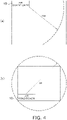
- FIG. 4 is an example of the air conditioning target area 101.
- options such as a large room and a small room are prepared in advance and manually selected by the user.
- FIG. 4(a) an area included in a range of a radius of 15 m from an installation location of the air conditioner 10 is set as a large room
- FIG. 4(b) an area included in a range of a diameter of 5 m from the installation location of the air conditioner 10 is set as a small room.
- Options related to a size of the room are displayed on the display 32 of the remote controller 30.
- the user uses the input part 34 of the remote controller 30 to select the size of the air conditioning target area 101 from the options displayed on the display 32.
- the second determination part 16 determines a determination criterion based on the information related to the size of the air conditioning target area 101 (step S14).
- the first acquisition part 12 acquires the radio wave intensity between the air conditioner 10 and the wearable sensor 20 as the first information (step S16).
- step S18 based on the first information acquired in step 16 and the determination criterion determined in step S14, the first determination part 14 determines whether the wearable sensor 20 is located in the air conditioning target area 101.
- the air conditioner 10 is controlled using the detection value of the wearable sensor 20 (step S20).
- step S18 the processing returns to step S16.
- the first determination part 14 determines that the detection values of the wearable sensors 20 worn by the plurality of users are not used for controlling the air conditioner 10 when all the users move and positions of the wearable sensors 20 worn by the plurality of users are changed from an inside of the air conditioning target area 101 to an outside of the air conditioning target area 101. After the positions of all the wearable sensors 20 connected to the air conditioner 10 are changed from an inside of the air conditioning target area 101 to an outside of the air conditioning target area 101 by the movement of the plurality of users, the operation of the air conditioner 10 is stopped or suppressed.
- the control system 100 is a control system that controls the air conditioner 10 that air-conditions the air conditioning target area 101 using the detection value of the wearable sensor 20 worn by the user.
- the control system 100 includes the first acquisition part 12, the first determination part 14, and the second determination part 16.
- the first acquisition part 12 acquires the first information related to the distance between the reference point of the air conditioning target area 101 and the wearable sensor 20.
- the first determination part 14 determines whether to use the detection value of the wearable sensor 20 for controlling the air conditioner 10 based on the first information and the determination criterion.
- the second determination part 16 determines the determination criterion.
- the air-conditioning control is more appropriately performed when the detection value of the wearable sensor 20 worn by the user is used for controlling the air conditioner 10.
- the air conditioner 10 can be controlled using biometric information of the user regardless of the size of the air conditioning target area 101.
- the first determination part 14 determines whether the wearable sensor 20 is located in the air conditioning target area 101 based on the first information and the determination criterion.
- the detection value of the wearable sensor 20 can be used for controlling the air conditioner 10.
- the first acquisition part 12 acquires the radio wave intensity between the air conditioner 10 and the wearable sensor 20 as the first information.
- the radio wave intensity can be used for determining whether to use the detection value of the wearable sensor 20 for controlling the air conditioner 10.
- the control system 100 further includes the second acquisition part 18 that acquires manually input information.
- the manually input information includes at least one of the information related to the size of the air conditioning target area 101 or the information related to the distance from the reference point of the air conditioning target area 101, and the second determination part 16 determines the determination criterion based on the information from the second acquisition part 18.
- initial setting of control of the air conditioner 10 can be performed by manually inputting information.
- the control system 100 further includes an automatic measurement part that automatically measures the size or the shape of the air conditioning target area 101, and the second determination part 16 determines the determination criterion based on a measurement result by the automatic measurement part.
- the size or the shape of the air conditioning target area 101 can be automatically measured to determine the determination criterion.
- the first determination part 14 determines that the detection values of the wearable sensors 20 are not used for controlling the air conditioner 10 when the positions of the wearable sensors 20 are changed from an inside of the air conditioning target area 101 to an outside of the air conditioning target area 101.
- the air-conditioning control is more appropriately performed when the detection values of the wearable sensors 20 worn by the plurality of users are used for controlling the air conditioner 10.
- control system 100 after the positions of all the biometric sensors connected to the air conditioner 10 are changed from an inside of the air conditioning target area 101 to an outside of the air conditioning target area 101, the operation of the air conditioner 10 is stopped or suppressed.
- control system 100 energy can be saved by stopping or suppressing the operation of the air conditioner 10.
- the air conditioner 10 and the wearable sensor 20 keep connected to each other when the position of the wearable sensor 20 is changed from an inside of the air conditioning target area 101 to an outside of the air conditioning target area 101.
- the detection value of the wearable sensor 20 can be promptly used.
- control of the air conditioner 10 when the detection value of the wearable sensor 20 is used in the air conditioning target area 101, the control of the air conditioner 10 is further changed in accordance with the distance.
- the weighting of the detection values of the wearable sensors far from the reference point is reduced, the weighting of the detection values of the wearable sensors close to the reference point is increased, and the detection values of the wearable sensors can be used for controlling the air conditioner.
- the options such as a large room and a small room are prepared in advance and are manually selected by the user.
- the present invention is not limited to this description.
- the user may manually input lengths of four sides of the room, and an installation company may select a position of the air conditioner such as a center, a left corner, or a right corner of a wall.
- the reachable range of the air conditioner in the air conditioning target area may be defined in association with communication intensity by bordering the room with a smartphone or the wearable sensor held by the user.
- control system 100 upon determination of the reachable range of the air conditioner 10 in the air conditioning target area 101, the options such as a large room and a small room are prepared in advance and are manually selected by the user in the above description.
- the control system 100 may further include the automatic measurement part that automatically measures the size or the shape of the air conditioning target area 101.
- the air conditioner 10 may include a radar sensor, and the shape of the air conditioning target area 101 may be detected using the radar sensor.
- the size or the shape of the air conditioning target area 101 may be detected by simultaneous localization and mapping (SLAM) by running a mobile unit into the air conditioning target area 101.
- SLAM simultaneous localization and mapping
- the reachable range of the air conditioner 10 in the air conditioning target area 101 may be defined from the detection result as to whether the user is in the air conditioning target area 101 and Bluetooth (registered trademark) communication intensity at a boundary between an area where the user is present and an area where the user is not present.
- the reachable range of the air conditioner 10 in the air conditioning target area 101 may be defined by image analysis using an optical sensor.
- the size of the air conditioning target area 101 estimated from a capability class of the air conditioner 10 and a rate of change in temperature in the air conditioning target area 101 may be assumed to be the reachable range of the air conditioner 10 in the air conditioning target area 101.
- the detection value of the wearable sensor 20 is used for controlling the air conditioner 10 in the above description.
- the air conditioner 10 and the wearable sensor 20 may keep connected to each other.
- the detection value of the biometric sensor 20 is used for controlling the air conditioner 10 when the biometric sensor (wearable sensor) 20 is in the air conditioning target area 101 in the above description.
- the control of the air conditioner 10 may be further changed in accordance with the distance.
- the detection values of both the first biometric sensor 20a and the second biometric sensor 20b are used for controlling the air conditioner 10 with the same weighting. For example, when the detection value of the first biometric sensor 20a is 25 degrees and the detection value of the second biometric sensor 20b is 27 degrees, the air conditioner 10 is controlled to 26 degrees.
- the weighting of the detection value of the first biometric sensor 20a is increased, the weighting of the detection value of the second biometric sensor 20b is decreased, and the detection values of the first biometric sensor 20a and the second biometric sensor 20b are used for controlling the air conditioner 10.
- the weighting of 25 degrees of the detection value of the first biometric sensor 20a is increased, and the weighting of 27 degrees of the detection value of second biometric sensor 20b is decreased, and thus the air conditioner is controlled to 25.5 degrees.
- the air conditioner 10 directly receives the radio wave from the wearable sensor 20 in the above description.
- the air conditioner 10 may receive the radio wave from the wearable sensor 20 via a relay device.
- a control system 200 includes the air conditioner 10, a biometric sensor 40, and a server 50.
- the air conditioner 10 is connected to the server 50 via a network 90.
- the smartphone (biometric sensor) 40 communicates with the server 50.
- the air conditioner 10 is an air conditioner having functions of cooling, heating, dehumidifying, and humidifying.
- the air conditioner 10 according to the present embodiment air-conditions the air conditioning target area 101 using a detection value of the biometric sensor 40 worn by the user.
- the air conditioner 10 includes a control unit 60.
- the configuration of the control unit 60 is basically the same as the configuration of the control system 100, and thus a detailed description thereof will be omitted.
- the biometric sensor 40 is a smartphone.
- the smartphone 40 includes a GPS 42, a display 44, and an input part 46.
- the display 44 displays options for allowing the user to manually input the information related to the size of the air conditioning target area 101.
- the input part 46 allows the user to manually input the information related to the size of the air conditioning target area 101.
- the smartphone 40 communicates with the server 50 to transmit the information input from the input part 46 of the smartphone 40 to the air conditioner 10.
- the air conditioner 10 communicates with the server 50 via the network 90.
- the smartphone 40 communicating with the server 50 displays the information and the like transmitted from the air conditioner 10 on the display 44.
- FIGS. 7A and 7B are flowcharts of the control system 200.
- the second acquisition part 18 acquires the information related to the size of the air conditioning target area 101 manually input from the input part 46 of the smartphone 40.
- the second determination part 16 determines a determination criterion based on the information related to the size of the air conditioning target area 101 (step S34).
- the first acquisition part 12 acquires a position of the reference point of the air conditioning target area 101 by the GPS 42 (step S36).
- the first acquisition part 12 acquires a position of the smartphone 40 by the GPS 42 (step S38).
- the first acquisition part 12 acquires, as the first information, distance information between the reference point of the air conditioning target area 101 and the smartphone 40 based on the information on the position of the reference point of the air conditioning target area 101 and the position of the smartphone 40 (step S40).
- step S42 based on the first information acquired in step S40 and the determination criterion determined in step S34, the first determination part 14 determines whether the smartphone 40 is located in the air conditioning target area 101.
- the air conditioner is controlled using the detection value of the smartphone 40 (step S42).
- step S40 When the first determination part 14 estimates that the smartphone 40 is not located in the air conditioning target area 101 (No in step S40), the processing returns to step S36.
- the first acquisition part 12 acquires the position of the reference point of the air conditioning target area 101 and the position of the biometric sensor 40 and thus acquires the distance information between the reference point of the air conditioning target area 101 and the biometric sensor 40 as the first information.
- the position information by the GPS 42 can be used for determining whether to use the detection value of the biometric sensor 40 for controlling the air conditioner 10.
- Patent Literature 1 Japanese Unexamined Patent Publication No. JP 2017-150702 A
Landscapes
- Engineering & Computer Science (AREA)
- General Engineering & Computer Science (AREA)
- Combustion & Propulsion (AREA)
- Mechanical Engineering (AREA)
- Chemical & Material Sciences (AREA)
- Human Computer Interaction (AREA)
- Theoretical Computer Science (AREA)
- Physics & Mathematics (AREA)
- General Physics & Mathematics (AREA)
- Signal Processing (AREA)
- Automation & Control Theory (AREA)
- Computer Networks & Wireless Communication (AREA)
- Air Conditioning Control Device (AREA)
- User Interface Of Digital Computer (AREA)
- Telephone Function (AREA)
Abstract
Description
- The present invention relates to a control system.
- Conventionally, a control device controls operation of an air conditioner based on air conditioning operation information associated with a terminal having a highest priority among terminals determined to exist within an effective range (Patent Literature 1 (Japanese Unexamined Patent Publication No.
JP 2017-150702 A - Conventionally, when a wearable terminal worn by a user is used for air-conditioning control, there is a problem that a threshold value related to distance information is unchangeable and there is difficulty in appropriately controlling the air conditioner.
- A control system according to a first aspect is a control system that controls an air conditioner that air-conditions an air conditioning target area using a detection value of a biometric sensor worn by a user. The control system according to the first aspect includes a first acquisition part, a first determination part, and a second determination part. The first acquisition part acquires first information related to a distance between a reference point of an air conditioning target area and the biometric sensor. The first determination part determines whether to use the detection value of the biometric sensor for controlling the air conditioner based on the first information and a determination criterion. The second determination part determines the determination criterion.
- In the control system, the air-conditioning control can be more appropriately performed when the detection value of the biometric sensor worn by the user is used for controlling the air conditioner.
- A control system according to a second aspect is the system according to the first aspect, in which the first determination part determines whether the biometric sensor is located in the air conditioning target area based on the first information and the determination criterion.
- In the control system, when the biometric sensor is located in the air conditioning target area, the detection value of the biometric sensor can be used for controlling the air conditioner.
- A control system according to a third aspect is the system according to the first or second aspect, in which the first acquisition part acquires radio wave intensity between the air conditioner and the biometric sensor as the first information.
- In the control system, the radio wave intensity can be used for determining whether to use the detection value of the biometric sensor for controlling the air conditioner.
- A control system according to a fourth aspect is the system according to the first or second aspect, in which the first acquisition part acquires the position of the reference point of the air conditioning target area and the position of the biometric sensor, respectively and thereby acquires the distance information between the reference point of the air conditioning target area and the biometric sensor as the first information.
- In the control system, position information can be used for determining whether to use the detection value of the biometric sensor for controlling the air conditioner.
- A control system according to a fifth aspect is the system according to the first aspect and further includes a second acquisition part that acquires manually input information. The manually input information includes at least one of the information related to a size of the air conditioning target area or the information related to the distance from the reference point of the air conditioning target area, and the second determination part determines the determination criterion based on the information from the second acquisition part.
- In the control system, initial setting of control of the air conditioner can be performed by manually inputting information.
- A control system according to a sixth aspect is the system according to the first aspect and further includes an automatic measurement part that automatically measures the size or a shape of the air conditioning target area, in which the second determination part determines the determination criterion based on a measurement result by the automatic measurement part.
- In this control system, the size or the shape of the air conditioning target area can be automatically measured to determine the determination criterion.
- A control system according to a seventh aspect is the system according to the first aspect, in which upon determination of whether to use detection values of biometric sensors worn by a plurality of users for controlling the air conditioner, the first determination part determines that the detection values of the biometric sensors is not used for controlling the air conditioner when positions of the biometric sensors are changed from an inside of the air conditioning target area to an outside of the air conditioning target area.
- In the control system, the air-conditioning control can be more appropriately performed when the detection values of the biometric sensors worn by the plurality of users are used for controlling the air conditioner.
- A control system according to an eighth aspect is the system according to the seventh aspect, in which after the positions of all the biometric sensors connected to the air conditioner are changed from inside of the air conditioning target area to outside of the air conditioning target area, the operation of the air conditioner is stopped or suppressed.
- In the control system, energy can be saved by stopping or suppressing the operation of the air conditioner.
- A control system according to a ninth aspect is the system according to the third aspect, in which the air conditioner and the biometric sensor keep connected to each other when the position of the biometric sensor is changed from inside of the air conditioning target area to outside of the air conditioning target area.
- In the control system, even when the user wearing the biometric sensor temporarily moves out of the air conditioning target area and then returns into the air conditioning target area, the detection value of the biometric sensor can be promptly used.
- A control system according to a tenth aspect is the system according to the first aspect, in which when the detection value of the biometric sensor is used in the air conditioning target area, the control of the air conditioner is further changed in accordance with the distance.
- In the control system, when the positions of some of the plurality of biometric sensors are far from the reference point of the air conditioner, weighting of the detection values of the biometric sensors far from the reference point is reduced, weighting of the detection values of the biometric sensors close to the reference point is increased, and the detection values of the biometric sensors can be used for controlling the air conditioner.
-
-
FIG. 1 is a conceptual diagram of an air conditioning target area. -
FIG. 2 is a functional block diagram of a control system. -
FIG. 3 is a flowchart of the control system. -
FIG. 4 is an example of the air conditioning target area. -
FIG. 5 is an example of control of an air conditioner. -
FIG. 6 is a functional block diagram of the control system. -
FIG. 7A is a flowchart of the control system. -
FIG. 7B is a flowchart of the control system. -
FIG. 1 is a conceptual diagram of an airconditioning target area 101. The airconditioning target area 101 is a space including anair conditioner 10. Auser 3a wearing abiometric sensor 2a and auser 3b wearing abiometric sensor 2b are present in the airconditioning target area 101. Theair conditioner 10 is controlled using detection values of thebiometric sensors users conditioning target area 101. - A
space 102 is separated from the airconditioning target area 101 by adoor 4 and is outside the airconditioning target area 101 of theair conditioner 10. Auser 3c having abiometric sensor 2c is present in thespace 102. A detection value of thebiometric sensor 2c worn by theuser 3c being present in thespace 102 is not used for controlling theair conditioner 10. -
FIG. 2 illustrates acontrol system 100 according to the present embodiment. Thecontrol system 100 includes theair conditioner 10, a wearable sensor (biometric sensor) 20, and aremote controller 30. - The
control system 100 according to the present embodiment controls theair conditioner 10 that air-conditions the airconditioning target area 101 using a detection value of thewearable sensor 20 worn by the user. The user uses theremote controller 30 to input information related to a size of the airconditioning target area 101 in which theair conditioner 10 is installed or the like. - The
air conditioner 10 is an air conditioner having functions of cooling, heating, dehumidifying, and humidifying. Theair conditioner 10 controls the airconditioning target area 101 using the detection value of thewearable sensor 20 worn by the user. - The
air conditioner 10 includes acontrol unit 60. - The
control unit 60 is achieved by a computer. Thecontrol unit 60 includes a control calculation unit and a storage unit. The control calculation unit may be a processor such as a CPU or a GPU. The control calculation unit reads a program stored in the storage unit and executes predetermined image processing or calculation processing in accordance with the program. The control calculation unit can write a calculation result to the storage unit and read information stored in the storage unit in accordance with the program.FIG. 2 illustrates various function blocks achieved by the control calculation unit. The storage unit can be used as database. - The
control unit 60 includes afirst acquisition part 12, afirst determination part 14, asecond determination part 16, and asecond acquisition part 18. - The
first acquisition part 12 acquires radio wave intensity between theair conditioner 10 and thewearable sensor 20 as first information. The first information is a parameter related to a distance between a reference point of the airconditioning target area 101 and thewearable sensor 20. - The
first determination part 14 determines whether thewearable sensor 20 is located in the airconditioning target area 101 based on the first information and a determination criterion. Thefirst determination part 14 determines whether to use the detection value of thewearable sensor 20 for controlling theair conditioner 10 based on the first information as radio wave information between the reference point of the airconditioning target area 101 and thewearable sensor 20 and the determination criterion. - The
second determination part 16 determines a determination criterion based on information from thesecond acquisition part 18. Here, the determination criterion is a threshold value related to the first information. - The
second acquisition part 18 acquires information manually input by the user using theremote controller 30. In thecontrol system 100, the manually input information is information related to the size of the airconditioning target area 101 in which theair conditioner 10 is installed. - In the
control system 100 according to the present embodiment, thebiometric sensor 20 is a wearable sensor. Theair conditioner 10 receives a radio wave from thewearable sensor 20 worn by the user. - The
remote controller 30 is a remote controller of theair conditioner 10. Theremote controller 30 bidirectionally communicates with theair conditioner 10. Theremote controller 30 includes adisplay 32 and aninput part 34. - The
display 32 displays options for allowing the user to manually input the information related to the size of the airconditioning target area 101. - The
input part 34 allows the user to manually input the information related to the size of the airconditioning target area 101. -
FIG. 3 is a flowchart of thecontrol system 100. - First, in step S12, the
second acquisition part 18 acquires the information related to the size of the airconditioning target area 101 manually input from theinput part 34 of theremote controller 30. -
FIG. 4 is an example of the airconditioning target area 101. Upon determination of a reachable range of theair conditioner 10 in the airconditioning target area 101, options such as a large room and a small room are prepared in advance and manually selected by the user. For example, as illustrated inFIG. 4(a) , an area included in a range of a radius of 15 m from an installation location of theair conditioner 10 is set as a large room, and as illustrated inFIG. 4(b) , an area included in a range of a diameter of 5 m from the installation location of theair conditioner 10 is set as a small room. Options related to a size of the room (the size of the air conditioning target area 101) are displayed on thedisplay 32 of theremote controller 30. The user uses theinput part 34 of theremote controller 30 to select the size of the airconditioning target area 101 from the options displayed on thedisplay 32. - The
second determination part 16 determines a determination criterion based on the information related to the size of the air conditioning target area 101 (step S14). - The
first acquisition part 12 acquires the radio wave intensity between theair conditioner 10 and thewearable sensor 20 as the first information (step S16). - Next, in step S18, based on the first information acquired in
step 16 and the determination criterion determined in step S14, thefirst determination part 14 determines whether thewearable sensor 20 is located in the airconditioning target area 101. - When the
first determination part 14 estimates that thewearable sensor 20 is located in the air conditioning target area 101 (Yes in step S18), theair conditioner 10 is controlled using the detection value of the wearable sensor 20 (step S20). - When the
first determination part 14 estimates that thewearable sensor 20 is not located in the air conditioning target area 101 (No in step S18), the processing returns to step S16. - Next, a case where a plurality of users are present in the air
conditioning target area 101 will be described. - Upon determination of whether to use the detection values of the
wearable sensors 20 worn by the plurality of users for controlling theair conditioner 10, thefirst determination part 14 determines that the detection values of thewearable sensors 20 worn by the plurality of users are not used for controlling theair conditioner 10 when all the users move and positions of thewearable sensors 20 worn by the plurality of users are changed from an inside of the airconditioning target area 101 to an outside of the airconditioning target area 101. After the positions of all thewearable sensors 20 connected to theair conditioner 10 are changed from an inside of the airconditioning target area 101 to an outside of the airconditioning target area 101 by the movement of the plurality of users, the operation of theair conditioner 10 is stopped or suppressed. - The
control system 100 according to the present embodiment is a control system that controls theair conditioner 10 that air-conditions the airconditioning target area 101 using the detection value of thewearable sensor 20 worn by the user. Thecontrol system 100 according to the present embodiment includes thefirst acquisition part 12, thefirst determination part 14, and thesecond determination part 16. Thefirst acquisition part 12 acquires the first information related to the distance between the reference point of the airconditioning target area 101 and thewearable sensor 20. Thefirst determination part 14 determines whether to use the detection value of thewearable sensor 20 for controlling theair conditioner 10 based on the first information and the determination criterion. Thesecond determination part 16 determines the determination criterion. - In the
control system 100, the air-conditioning control is more appropriately performed when the detection value of thewearable sensor 20 worn by the user is used for controlling theair conditioner 10. In thecontrol system 100, by determining the determination criterion for determining whether to use the detection value of thewearable sensor 20 worn by the user for the air conditioning control, theair conditioner 10 can be controlled using biometric information of the user regardless of the size of the airconditioning target area 101. - In the
control system 100 according to the present embodiment, thefirst determination part 14 determines whether thewearable sensor 20 is located in the airconditioning target area 101 based on the first information and the determination criterion. - In the
control system 100, when thewearable sensor 20 is located in the airconditioning target area 101, the detection value of thewearable sensor 20 can be used for controlling theair conditioner 10. - In the
control system 100 according to the present embodiment, thefirst acquisition part 12 acquires the radio wave intensity between theair conditioner 10 and thewearable sensor 20 as the first information. - In the
control system 100, the radio wave intensity can be used for determining whether to use the detection value of thewearable sensor 20 for controlling theair conditioner 10. - The
control system 100 according to the present embodiment further includes thesecond acquisition part 18 that acquires manually input information. The manually input information includes at least one of the information related to the size of the airconditioning target area 101 or the information related to the distance from the reference point of the airconditioning target area 101, and thesecond determination part 16 determines the determination criterion based on the information from thesecond acquisition part 18. - In the
control system 100, initial setting of control of theair conditioner 10 can be performed by manually inputting information. - The
control system 100 according to the present embodiment further includes an automatic measurement part that automatically measures the size or the shape of the airconditioning target area 101, and thesecond determination part 16 determines the determination criterion based on a measurement result by the automatic measurement part. - In this control system, the size or the shape of the air
conditioning target area 101 can be automatically measured to determine the determination criterion. - In the
control system 100 according to the present embodiment, upon determination of whether to use the detection values of thewearable sensors 20 worn by the plurality of users for controlling theair conditioner 10, thefirst determination part 14 determines that the detection values of thewearable sensors 20 are not used for controlling theair conditioner 10 when the positions of thewearable sensors 20 are changed from an inside of the airconditioning target area 101 to an outside of the airconditioning target area 101. - In the
control system 100, the air-conditioning control is more appropriately performed when the detection values of thewearable sensors 20 worn by the plurality of users are used for controlling theair conditioner 10. - In the
control system 100 according to the present embodiment, after the positions of all the biometric sensors connected to theair conditioner 10 are changed from an inside of the airconditioning target area 101 to an outside of the airconditioning target area 101, the operation of theair conditioner 10 is stopped or suppressed. - In the
control system 100, energy can be saved by stopping or suppressing the operation of theair conditioner 10. - In the
control system 100 according to the present embodiment, theair conditioner 10 and thewearable sensor 20 keep connected to each other when the position of thewearable sensor 20 is changed from an inside of the airconditioning target area 101 to an outside of the airconditioning target area 101. - In the
control system 100, even when the user wearing thewearable sensor 20 temporarily moves out of the airconditioning target area 101 and then returns into the airconditioning target area 101, the detection value of thewearable sensor 20 can be promptly used. - In the
control system 100 according to the present embodiment, when the detection value of thewearable sensor 20 is used in the airconditioning target area 101, the control of theair conditioner 10 is further changed in accordance with the distance. - In the
control system 100, when the positions of some of the plurality of wearable sensors are far from the reference point of the air conditioner, the weighting of the detection values of the wearable sensors far from the reference point is reduced, the weighting of the detection values of the wearable sensors close to the reference point is increased, and the detection values of the wearable sensors can be used for controlling the air conditioner. - In the
control system 100 according to the present embodiment, upon determination of the reachable range of theair conditioner 10 in the airconditioning target area 101, the options such as a large room and a small room are prepared in advance and are manually selected by the user. However, the present invention is not limited to this description. Upon determination of the reachable range of theair conditioner 10 in the airconditioning target area 101, for example, assuming that a room is simply a quadrangle, the user may manually input lengths of four sides of the room, and an installation company may select a position of the air conditioner such as a center, a left corner, or a right corner of a wall. The reachable range of the air conditioner in the air conditioning target area may be defined in association with communication intensity by bordering the room with a smartphone or the wearable sensor held by the user. - In the
control system 100 according to the present embodiment, upon determination of the reachable range of theair conditioner 10 in the airconditioning target area 101, the options such as a large room and a small room are prepared in advance and are manually selected by the user in the above description. Alternatively, thecontrol system 100 may further include the automatic measurement part that automatically measures the size or the shape of the airconditioning target area 101. For example, theair conditioner 10 may include a radar sensor, and the shape of the airconditioning target area 101 may be detected using the radar sensor. The size or the shape of the airconditioning target area 101 may be detected by simultaneous localization and mapping (SLAM) by running a mobile unit into the airconditioning target area 101. The reachable range of theair conditioner 10 in the airconditioning target area 101 may be defined from the detection result as to whether the user is in the airconditioning target area 101 and Bluetooth (registered trademark) communication intensity at a boundary between an area where the user is present and an area where the user is not present. The reachable range of theair conditioner 10 in the airconditioning target area 101 may be defined by image analysis using an optical sensor. The size of the airconditioning target area 101 estimated from a capability class of theair conditioner 10 and a rate of change in temperature in the airconditioning target area 101 may be assumed to be the reachable range of theair conditioner 10 in the airconditioning target area 101. - In the
control system 100 according to the present embodiment, when thewearable sensor 20 is located in the airconditioning target area 101, the detection value of thewearable sensor 20 is used for controlling theair conditioner 10 in the above description. When the position of thewearable sensor 20 is changed from an inside of the airconditioning target area 101 to an outside of the airconditioning target area 101, theair conditioner 10 and thewearable sensor 20 may keep connected to each other. - In the
control system 100 according to the present embodiment, the detection value of thebiometric sensor 20 is used for controlling theair conditioner 10 when the biometric sensor (wearable sensor) 20 is in the airconditioning target area 101 in the above description. When the detection value of thebiometric sensor 20 is used in the airconditioning target area 101, the control of theair conditioner 10 may be further changed in accordance with the distance. - As illustrated in
FIG. 5(a) , when the firstbiometric sensor 20a and the secondbiometric sensor 20b are located close to the air conditioner, the detection values of both the firstbiometric sensor 20a and the secondbiometric sensor 20b are used for controlling theair conditioner 10 with the same weighting. For example, when the detection value of the firstbiometric sensor 20a is 25 degrees and the detection value of the secondbiometric sensor 20b is 27 degrees, theair conditioner 10 is controlled to 26 degrees. - As illustrated in
FIG. 5(b) , when the firstbiometric sensor 20a is located close to theair conditioner 10 but the secondbiometric sensor 20b is located away from theair conditioner 10, the weighting of the detection value of the firstbiometric sensor 20a is increased, the weighting of the detection value of the secondbiometric sensor 20b is decreased, and the detection values of the firstbiometric sensor 20a and the secondbiometric sensor 20b are used for controlling theair conditioner 10. In this case, the weighting of 25 degrees of the detection value of the firstbiometric sensor 20a is increased, and the weighting of 27 degrees of the detection value of secondbiometric sensor 20b is decreased, and thus the air conditioner is controlled to 25.5 degrees. - In the
control system 100 according to the present embodiment, theair conditioner 10 directly receives the radio wave from thewearable sensor 20 in the above description. Alternatively, theair conditioner 10 may receive the radio wave from thewearable sensor 20 via a relay device. - As shown in
FIG. 6 , acontrol system 200 according to the present embodiment includes theair conditioner 10, abiometric sensor 40, and aserver 50. Theair conditioner 10 is connected to theserver 50 via anetwork 90. The smartphone (biometric sensor) 40 communicates with theserver 50. - The
air conditioner 10 is an air conditioner having functions of cooling, heating, dehumidifying, and humidifying. Theair conditioner 10 according to the present embodiment air-conditions the airconditioning target area 101 using a detection value of thebiometric sensor 40 worn by the user. - The
air conditioner 10 includes acontrol unit 60. Note that, in thecontrol system 200 according to the present embodiment, the configuration of thecontrol unit 60 is basically the same as the configuration of thecontrol system 100, and thus a detailed description thereof will be omitted. - In the
control system 200 according to the present embodiment, thebiometric sensor 40 is a smartphone. Thesmartphone 40 includes aGPS 42, adisplay 44, and aninput part 46. - The
display 44 displays options for allowing the user to manually input the information related to the size of the airconditioning target area 101. - The
input part 46 allows the user to manually input the information related to the size of the airconditioning target area 101. - The
smartphone 40 communicates with theserver 50 to transmit the information input from theinput part 46 of thesmartphone 40 to theair conditioner 10. Theair conditioner 10 communicates with theserver 50 via thenetwork 90. Thesmartphone 40 communicating with theserver 50 displays the information and the like transmitted from theair conditioner 10 on thedisplay 44. -
FIGS. 7A and7B are flowcharts of thecontrol system 200. - First, in
step 32, thesecond acquisition part 18 acquires the information related to the size of the airconditioning target area 101 manually input from theinput part 46 of thesmartphone 40. - The
second determination part 16 determines a determination criterion based on the information related to the size of the air conditioning target area 101 (step S34). - The
first acquisition part 12 acquires a position of the reference point of the airconditioning target area 101 by the GPS 42 (step S36). Thefirst acquisition part 12 acquires a position of thesmartphone 40 by the GPS 42 (step S38). - The
first acquisition part 12 acquires, as the first information, distance information between the reference point of the airconditioning target area 101 and thesmartphone 40 based on the information on the position of the reference point of the airconditioning target area 101 and the position of the smartphone 40 (step S40). - Next, in step S42, based on the first information acquired in step S40 and the determination criterion determined in step S34, the
first determination part 14 determines whether thesmartphone 40 is located in the airconditioning target area 101. - When the
first determination part 14 estimates that thesmartphone 40 is located in the air conditioning target area 101 (Yes in step S40), the air conditioner is controlled using the detection value of the smartphone 40 (step S42). - When the
first determination part 14 estimates that thesmartphone 40 is not located in the air conditioning target area 101 (No in step S40), the processing returns to step S36. - In the
control system 200 according to the present embodiment, thefirst acquisition part 12 acquires the position of the reference point of the airconditioning target area 101 and the position of thebiometric sensor 40 and thus acquires the distance information between the reference point of the airconditioning target area 101 and thebiometric sensor 40 as the first information. - In the
control system 200, the position information by theGPS 42 can be used for determining whether to use the detection value of thebiometric sensor 40 for controlling theair conditioner 10. - The modifications 1A to 1D described in the first embodiment are similarly applied to the
control system 200 according to the present embodiment. - The embodiments of the present disclosure have been described above. Various modifications to modes and details should be available without departing from the object and the scope of the present disclosure recited in the claims.
-
- 100, 200: control system
- 101: air conditioning target area
- 10: air conditioner
- 2a, 2b, 2c, 20a, 20b: biometric sensor
- 20: wearable sensor (biometric sensor)
- 3a, 3b, 3c: user
- 20a: first biometric sensor
- 20b: second biometric sensor
- 30: remote controller
- 32, 44: display
- 34, 46: input part
- 40: smartphone (biometric sensor)
- 42: GPS
- 50: server
- 52: storage unit
- 90: network
- 12: first acquisition part
- 14: first determination part
- 16: second determination part
- 18: second acquisition part
- Patent Literature 1: Japanese Unexamined Patent Publication No.
JP 2017-150702 A
Claims (10)
- A control system (100, 200) that controls an air conditioner (10) that air-conditions an air conditioning target area (101) using a detection value of a biometric sensor (20, 40) worn by a user, the control system comprising:a first acquisition part (12) that acquires first information related to a distance between a reference point of the air conditioning target area and the biometric sensor;a first determination part (14) that determines whether to use a detection value of the biometric sensor for controlling the air conditioner based on the first information and a determination criterion; anda second determination part (16) that determines the determination criterion.
- The control system according to claim 1, wherein the first determination part determines whether the biometric sensor is located in the air conditioning target area based on the first information and the determination criterion.
- The control system according to claim 1 or 2, wherein the first acquisition part acquires radio wave intensity between the air conditioner and the biometric sensor as the first information.
- The control system according to claim 1 or 2, wherein the first acquisition part acquires a position of the reference point of the air conditioning target area and a position of the biometric sensor and thus acquires distance information between the reference point of the air conditioning target area and the biometric sensor as the first information.
- The control system according to claim 1, further comprising a second acquisition part (18) that acquires information manually input, whereinthe information manually input includes at least one of information related to a size of the air conditioning target area or information related to the distance from the reference point of the air conditioning target area, andthe second determination part determines the determination criterion based on the information from the second acquisition part.
- The control system according to claim 1 further comprising an automatic measurement part that automatically measures the size or a shape of the air conditioning target area, wherein the second determination part determines the determination criterion based on a measurement result by the automatic measurement part.
- The control system according to claim 1, wherein upon determination of whether to use detection values of biometric sensors worn by a plurality of users for controlling the air conditioner, the first determination part determines that the detection values of the biometric sensors is not used for controlling the air conditioner when positions of the biometric sensors are changed from an inside of the air conditioning target area to an outside of the air conditioning target area.
- The control system according to claim 7, wherein after the positions of all the biometric sensors connected to the air conditioner are changed from an inside of the air conditioning target area to an outside of the air conditioning target area, operation of the air conditioner is stopped or suppressed.
- The control system according to claim 3, wherein the air conditioner and the biometric sensor keep connected to each other when the position of the biometric sensor is changed from an inside of the air conditioning target area to an outside of the air conditioning target area.
- The control system according to claim 1, when the detection value of the biometric sensor is used in the air conditioning target area, control of the air conditioner is changed in accordance with the distance.
Applications Claiming Priority (2)
| Application Number | Priority Date | Filing Date | Title |
|---|---|---|---|
| JP2019180833A JP2021055962A (en) | 2019-09-30 | 2019-09-30 | Control system |
| PCT/JP2020/036088 WO2021065680A1 (en) | 2019-09-30 | 2020-09-24 | Control system |
Publications (3)
| Publication Number | Publication Date |
|---|---|
| EP4040065A1 true EP4040065A1 (en) | 2022-08-10 |
| EP4040065A4 EP4040065A4 (en) | 2022-11-16 |
| EP4040065B1 EP4040065B1 (en) | 2024-05-01 |
Family
ID=75270586
Family Applications (1)
| Application Number | Title | Priority Date | Filing Date |
|---|---|---|---|
| EP20872564.8A Active EP4040065B1 (en) | 2019-09-30 | 2020-09-24 | Control system |
Country Status (5)
| Country | Link |
|---|---|
| US (1) | US20220221180A1 (en) |
| EP (1) | EP4040065B1 (en) |
| JP (1) | JP2021055962A (en) |
| CN (1) | CN114502892A (en) |
| WO (1) | WO2021065680A1 (en) |
Families Citing this family (1)
| Publication number | Priority date | Publication date | Assignee | Title |
|---|---|---|---|---|
| WO2025155813A1 (en) * | 2024-01-19 | 2025-07-24 | Mojave Energy Systems, Inc. | Apparatus and methods for user interface for efficient analysis and selection of desiccant hvac systems |
Family Cites Families (19)
| Publication number | Priority date | Publication date | Assignee | Title |
|---|---|---|---|---|
| JP5183408B2 (en) * | 2008-10-06 | 2013-04-17 | 日立アプライアンス株式会社 | Air conditioner |
| JP5836741B2 (en) * | 2011-09-30 | 2015-12-24 | 日立アプライアンス株式会社 | Air conditioning control terminal and air conditioning control setting operation method |
| CN102495617A (en) * | 2011-12-29 | 2012-06-13 | 深圳Tcl新技术有限公司 | Intelligent household air-conditioning system with linkage function |
| CN103245035A (en) * | 2012-02-10 | 2013-08-14 | 大金工业株式会社 | Air conditioning control system and air conditioning control method |
| JP2015078802A (en) * | 2013-10-18 | 2015-04-23 | 日立アプライアンス株式会社 | Indoor unit of air conditioning device and air conditioning device |
| JP5975973B2 (en) * | 2013-12-10 | 2016-08-23 | 三菱電機株式会社 | Air conditioning control device and air conditioning system |
| US20160061472A1 (en) * | 2014-09-02 | 2016-03-03 | Samsung Electronics Co., Ltd. | Method and device for controlling room temperature and humidity |
| CN104279712A (en) * | 2014-10-13 | 2015-01-14 | 广东美的制冷设备有限公司 | Air conditioner control method and air conditioner |
| CN105159105B (en) * | 2015-08-13 | 2019-06-14 | 小米科技有限责任公司 | Intelligent electric appliance working method and device |
| US10310477B2 (en) * | 2015-10-28 | 2019-06-04 | Johnson Controls Technology Company | Multi-function thermostat with occupant tracking features |
| US20170123440A1 (en) * | 2015-10-29 | 2017-05-04 | Honeywell International Inc. | Crowd comfortable settings |
| US10516965B2 (en) * | 2015-11-11 | 2019-12-24 | Ademco Inc. | HVAC control using geofencing |
| JP2017150702A (en) | 2016-02-23 | 2017-08-31 | 三菱重工サーマルシステムズ株式会社 | Controller, air conditioning system, control method and program |
| JPWO2017179386A1 (en) * | 2016-04-15 | 2019-02-28 | パナソニックIpマネジメント株式会社 | Equipment management system |
| DE112016006863T5 (en) * | 2016-05-16 | 2019-02-14 | Mitsubishi Electric Corporation | Management device and air conditioning |
| JP6790249B2 (en) * | 2017-05-01 | 2020-11-25 | 三菱電機株式会社 | Air conditioners, air conditioners, air conditioners and programs |
| CN109751742B (en) * | 2017-11-01 | 2022-03-29 | 开利公司 | Biometric and device control of a predetermined spatial region |
| US20190242605A1 (en) * | 2018-02-08 | 2019-08-08 | Carrier Corporation | Controlling a heating, ventilation and air conditioning (hvac) system with networked hvac zone sensors |
| WO2020050174A1 (en) * | 2018-09-03 | 2020-03-12 | ダイキン工業株式会社 | Ventilation control device and ventilation system |
-
2019
- 2019-09-30 JP JP2019180833A patent/JP2021055962A/en active Pending
-
2020
- 2020-09-24 WO PCT/JP2020/036088 patent/WO2021065680A1/en not_active Ceased
- 2020-09-24 EP EP20872564.8A patent/EP4040065B1/en active Active
- 2020-09-24 CN CN202080068200.4A patent/CN114502892A/en active Pending
-
2022
- 2022-03-29 US US17/707,664 patent/US20220221180A1/en not_active Abandoned
Also Published As
| Publication number | Publication date |
|---|---|
| WO2021065680A1 (en) | 2021-04-08 |
| JP2021055962A (en) | 2021-04-08 |
| EP4040065B1 (en) | 2024-05-01 |
| US20220221180A1 (en) | 2022-07-14 |
| CN114502892A (en) | 2022-05-13 |
| EP4040065A4 (en) | 2022-11-16 |
Similar Documents
| Publication | Publication Date | Title |
|---|---|---|
| EP2479507B1 (en) | Air conditioner control device, air conditioning system, facility/equipment system | |
| US10708077B2 (en) | Technologies for optimally individualized building automation | |
| US11368328B2 (en) | Method for controlling terminal apparatus that remotely controls air conditioner, non-transitory recording medium storing program executed by terminal apparatus, recommend method executed by terminal apparatus, and terminal apparatus | |
| US20140141795A1 (en) | Apparatus and Method for Performing Low-Power Geo-Fence Operations | |
| CN108759003B (en) | Air conditioner control method, air conditioner, and computer-readable storage medium | |
| US10054328B2 (en) | Operational conditioning based on environmental components | |
| JP7450448B2 (en) | Management device, air conditioning system, and air conditioner setting method | |
| EP3270073B1 (en) | Air conditioning control device | |
| CN107852569B (en) | Terminal and method for measuring position of terminal | |
| CN110529987B (en) | Biological characteristic air conditioner control system | |
| EP3604961A1 (en) | Windless feeling control method and device and computer readable storage medium | |
| EP4040065B1 (en) | Control system | |
| US20210231339A1 (en) | Controller and air conditioning system | |
| EP3860138B1 (en) | Air conditioning system | |
| JP7054782B2 (en) | Control information output system, device control system, device control method, and program | |
| US11181292B2 (en) | Information output system, device control system, information output method, and program | |
| WO2017208344A1 (en) | Air conditioning system | |
| EP3859221A1 (en) | Air conditioning system and application program | |
| US20230171123A1 (en) | Electronic device for controlling external device based on occupant monitoring system, and method thereof | |
| EP4171055A1 (en) | Equipment control system, user terminal, equipment control method, and program | |
| JP2026003191A (en) | Remote control device and air conditioning system | |
| US11422539B2 (en) | Control system, control method, and program | |
| KR102002076B1 (en) | IoT DISTRIBUTED PROCESSING SYSTEM AND METHOD BASED ON RESOURCE ALLOCATION ALGORITHM | |
| EP4006440B1 (en) | Facility device management system | |
| EP4050361A1 (en) | Facility equipment control system, information terminal, location identification method, and program |
Legal Events
| Date | Code | Title | Description |
|---|---|---|---|
| STAA | Information on the status of an ep patent application or granted ep patent |
Free format text: STATUS: THE INTERNATIONAL PUBLICATION HAS BEEN MADE |
|
| PUAI | Public reference made under article 153(3) epc to a published international application that has entered the european phase |
Free format text: ORIGINAL CODE: 0009012 |
|
| STAA | Information on the status of an ep patent application or granted ep patent |
Free format text: STATUS: REQUEST FOR EXAMINATION WAS MADE |
|
| 17P | Request for examination filed |
Effective date: 20220422 |
|
| AK | Designated contracting states |
Kind code of ref document: A1 Designated state(s): AL AT BE BG CH CY CZ DE DK EE ES FI FR GB GR HR HU IE IS IT LI LT LU LV MC MK MT NL NO PL PT RO RS SE SI SK SM TR |
|
| A4 | Supplementary search report drawn up and despatched |
Effective date: 20221014 |
|
| RIC1 | Information provided on ipc code assigned before grant |
Ipc: H04L 12/28 20060101ALI20221010BHEP Ipc: G06F 3/01 20060101ALI20221010BHEP Ipc: F24F 11/46 20180101AFI20221010BHEP |
|
| DAV | Request for validation of the european patent (deleted) | ||
| DAX | Request for extension of the european patent (deleted) | ||
| RAP3 | Party data changed (applicant data changed or rights of an application transferred) |
Owner name: DAIKIN INDUSTRIES, LTD. |
|
| STAA | Information on the status of an ep patent application or granted ep patent |
Free format text: STATUS: EXAMINATION IS IN PROGRESS |
|
| P01 | Opt-out of the competence of the unified patent court (upc) registered |
Effective date: 20230525 |
|
| 17Q | First examination report despatched |
Effective date: 20230630 |
|
| RIC1 | Information provided on ipc code assigned before grant |
Ipc: H04L 12/28 20060101ALI20231129BHEP Ipc: G06F 3/01 20060101ALI20231129BHEP Ipc: F24F 11/46 20180101AFI20231129BHEP |
|
| GRAP | Despatch of communication of intention to grant a patent |
Free format text: ORIGINAL CODE: EPIDOSNIGR1 |
|
| STAA | Information on the status of an ep patent application or granted ep patent |
Free format text: STATUS: GRANT OF PATENT IS INTENDED |
|
| INTG | Intention to grant announced |
Effective date: 20240108 |
|
| GRAS | Grant fee paid |
Free format text: ORIGINAL CODE: EPIDOSNIGR3 |
|
| GRAA | (expected) grant |
Free format text: ORIGINAL CODE: 0009210 |
|
| STAA | Information on the status of an ep patent application or granted ep patent |
Free format text: STATUS: THE PATENT HAS BEEN GRANTED |
|
| AK | Designated contracting states |
Kind code of ref document: B1 Designated state(s): AL AT BE BG CH CY CZ DE DK EE ES FI FR GB GR HR HU IE IS IT LI LT LU LV MC MK MT NL NO PL PT RO RS SE SI SK SM TR |
|
| REG | Reference to a national code |
Ref country code: GB Ref legal event code: FG4D |
|
| REG | Reference to a national code |
Ref country code: CH Ref legal event code: EP |
|
| REG | Reference to a national code |
Ref country code: IE Ref legal event code: FG4D |
|
| REG | Reference to a national code |
Ref country code: DE Ref legal event code: R096 Ref document number: 602020030417 Country of ref document: DE |
|
| REG | Reference to a national code |
Ref country code: LT Ref legal event code: MG9D |
|
| REG | Reference to a national code |
Ref country code: NL Ref legal event code: MP Effective date: 20240501 |
|
| PG25 | Lapsed in a contracting state [announced via postgrant information from national office to epo] |
Ref country code: IS Free format text: LAPSE BECAUSE OF FAILURE TO SUBMIT A TRANSLATION OF THE DESCRIPTION OR TO PAY THE FEE WITHIN THE PRESCRIBED TIME-LIMIT Effective date: 20240901 |
|
| PG25 | Lapsed in a contracting state [announced via postgrant information from national office to epo] |
Ref country code: BG Free format text: LAPSE BECAUSE OF FAILURE TO SUBMIT A TRANSLATION OF THE DESCRIPTION OR TO PAY THE FEE WITHIN THE PRESCRIBED TIME-LIMIT Effective date: 20240501 |
|
| PG25 | Lapsed in a contracting state [announced via postgrant information from national office to epo] |
Ref country code: FI Free format text: LAPSE BECAUSE OF FAILURE TO SUBMIT A TRANSLATION OF THE DESCRIPTION OR TO PAY THE FEE WITHIN THE PRESCRIBED TIME-LIMIT Effective date: 20240501 Ref country code: HR Free format text: LAPSE BECAUSE OF FAILURE TO SUBMIT A TRANSLATION OF THE DESCRIPTION OR TO PAY THE FEE WITHIN THE PRESCRIBED TIME-LIMIT Effective date: 20240501 |
|
| PG25 | Lapsed in a contracting state [announced via postgrant information from national office to epo] |
Ref country code: GR Free format text: LAPSE BECAUSE OF FAILURE TO SUBMIT A TRANSLATION OF THE DESCRIPTION OR TO PAY THE FEE WITHIN THE PRESCRIBED TIME-LIMIT Effective date: 20240802 |
|
| PG25 | Lapsed in a contracting state [announced via postgrant information from national office to epo] |
Ref country code: PT Free format text: LAPSE BECAUSE OF FAILURE TO SUBMIT A TRANSLATION OF THE DESCRIPTION OR TO PAY THE FEE WITHIN THE PRESCRIBED TIME-LIMIT Effective date: 20240902 |
|
| REG | Reference to a national code |
Ref country code: AT Ref legal event code: MK05 Ref document number: 1682835 Country of ref document: AT Kind code of ref document: T Effective date: 20240501 |
|
| PG25 | Lapsed in a contracting state [announced via postgrant information from national office to epo] |
Ref country code: NL Free format text: LAPSE BECAUSE OF FAILURE TO SUBMIT A TRANSLATION OF THE DESCRIPTION OR TO PAY THE FEE WITHIN THE PRESCRIBED TIME-LIMIT Effective date: 20240501 |
|
| PG25 | Lapsed in a contracting state [announced via postgrant information from national office to epo] |
Ref country code: ES Free format text: LAPSE BECAUSE OF FAILURE TO SUBMIT A TRANSLATION OF THE DESCRIPTION OR TO PAY THE FEE WITHIN THE PRESCRIBED TIME-LIMIT Effective date: 20240501 |
|
| PG25 | Lapsed in a contracting state [announced via postgrant information from national office to epo] |
Ref country code: AT Free format text: LAPSE BECAUSE OF FAILURE TO SUBMIT A TRANSLATION OF THE DESCRIPTION OR TO PAY THE FEE WITHIN THE PRESCRIBED TIME-LIMIT Effective date: 20240501 |
|
| PG25 | Lapsed in a contracting state [announced via postgrant information from national office to epo] |
Ref country code: PL Free format text: LAPSE BECAUSE OF FAILURE TO SUBMIT A TRANSLATION OF THE DESCRIPTION OR TO PAY THE FEE WITHIN THE PRESCRIBED TIME-LIMIT Effective date: 20240501 |
|
| PG25 | Lapsed in a contracting state [announced via postgrant information from national office to epo] |
Ref country code: LV Free format text: LAPSE BECAUSE OF FAILURE TO SUBMIT A TRANSLATION OF THE DESCRIPTION OR TO PAY THE FEE WITHIN THE PRESCRIBED TIME-LIMIT Effective date: 20240501 |
|
| PG25 | Lapsed in a contracting state [announced via postgrant information from national office to epo] |
Ref country code: PT Free format text: LAPSE BECAUSE OF FAILURE TO SUBMIT A TRANSLATION OF THE DESCRIPTION OR TO PAY THE FEE WITHIN THE PRESCRIBED TIME-LIMIT Effective date: 20240902 Ref country code: PL Free format text: LAPSE BECAUSE OF FAILURE TO SUBMIT A TRANSLATION OF THE DESCRIPTION OR TO PAY THE FEE WITHIN THE PRESCRIBED TIME-LIMIT Effective date: 20240501 Ref country code: NO Free format text: LAPSE BECAUSE OF FAILURE TO SUBMIT A TRANSLATION OF THE DESCRIPTION OR TO PAY THE FEE WITHIN THE PRESCRIBED TIME-LIMIT Effective date: 20240801 Ref country code: NL Free format text: LAPSE BECAUSE OF FAILURE TO SUBMIT A TRANSLATION OF THE DESCRIPTION OR TO PAY THE FEE WITHIN THE PRESCRIBED TIME-LIMIT Effective date: 20240501 Ref country code: LV Free format text: LAPSE BECAUSE OF FAILURE TO SUBMIT A TRANSLATION OF THE DESCRIPTION OR TO PAY THE FEE WITHIN THE PRESCRIBED TIME-LIMIT Effective date: 20240501 Ref country code: IS Free format text: LAPSE BECAUSE OF FAILURE TO SUBMIT A TRANSLATION OF THE DESCRIPTION OR TO PAY THE FEE WITHIN THE PRESCRIBED TIME-LIMIT Effective date: 20240901 Ref country code: HR Free format text: LAPSE BECAUSE OF FAILURE TO SUBMIT A TRANSLATION OF THE DESCRIPTION OR TO PAY THE FEE WITHIN THE PRESCRIBED TIME-LIMIT Effective date: 20240501 Ref country code: GR Free format text: LAPSE BECAUSE OF FAILURE TO SUBMIT A TRANSLATION OF THE DESCRIPTION OR TO PAY THE FEE WITHIN THE PRESCRIBED TIME-LIMIT Effective date: 20240802 Ref country code: FI Free format text: LAPSE BECAUSE OF FAILURE TO SUBMIT A TRANSLATION OF THE DESCRIPTION OR TO PAY THE FEE WITHIN THE PRESCRIBED TIME-LIMIT Effective date: 20240501 Ref country code: ES Free format text: LAPSE BECAUSE OF FAILURE TO SUBMIT A TRANSLATION OF THE DESCRIPTION OR TO PAY THE FEE WITHIN THE PRESCRIBED TIME-LIMIT Effective date: 20240501 Ref country code: BG Free format text: LAPSE BECAUSE OF FAILURE TO SUBMIT A TRANSLATION OF THE DESCRIPTION OR TO PAY THE FEE WITHIN THE PRESCRIBED TIME-LIMIT Effective date: 20240501 Ref country code: AT Free format text: LAPSE BECAUSE OF FAILURE TO SUBMIT A TRANSLATION OF THE DESCRIPTION OR TO PAY THE FEE WITHIN THE PRESCRIBED TIME-LIMIT Effective date: 20240501 Ref country code: RS Free format text: LAPSE BECAUSE OF FAILURE TO SUBMIT A TRANSLATION OF THE DESCRIPTION OR TO PAY THE FEE WITHIN THE PRESCRIBED TIME-LIMIT Effective date: 20240801 |
|
| PG25 | Lapsed in a contracting state [announced via postgrant information from national office to epo] |
Ref country code: DK Free format text: LAPSE BECAUSE OF FAILURE TO SUBMIT A TRANSLATION OF THE DESCRIPTION OR TO PAY THE FEE WITHIN THE PRESCRIBED TIME-LIMIT Effective date: 20240501 |
|
| PG25 | Lapsed in a contracting state [announced via postgrant information from national office to epo] |
Ref country code: EE Free format text: LAPSE BECAUSE OF FAILURE TO SUBMIT A TRANSLATION OF THE DESCRIPTION OR TO PAY THE FEE WITHIN THE PRESCRIBED TIME-LIMIT Effective date: 20240501 |
|
| PG25 | Lapsed in a contracting state [announced via postgrant information from national office to epo] |
Ref country code: CZ Free format text: LAPSE BECAUSE OF FAILURE TO SUBMIT A TRANSLATION OF THE DESCRIPTION OR TO PAY THE FEE WITHIN THE PRESCRIBED TIME-LIMIT Effective date: 20240501 |
|
| PG25 | Lapsed in a contracting state [announced via postgrant information from national office to epo] |
Ref country code: RO Free format text: LAPSE BECAUSE OF FAILURE TO SUBMIT A TRANSLATION OF THE DESCRIPTION OR TO PAY THE FEE WITHIN THE PRESCRIBED TIME-LIMIT Effective date: 20240501 Ref country code: SK Free format text: LAPSE BECAUSE OF FAILURE TO SUBMIT A TRANSLATION OF THE DESCRIPTION OR TO PAY THE FEE WITHIN THE PRESCRIBED TIME-LIMIT Effective date: 20240501 |
|
| PG25 | Lapsed in a contracting state [announced via postgrant information from national office to epo] |
Ref country code: SM Free format text: LAPSE BECAUSE OF FAILURE TO SUBMIT A TRANSLATION OF THE DESCRIPTION OR TO PAY THE FEE WITHIN THE PRESCRIBED TIME-LIMIT Effective date: 20240501 |
|
| PG25 | Lapsed in a contracting state [announced via postgrant information from national office to epo] |
Ref country code: SM Free format text: LAPSE BECAUSE OF FAILURE TO SUBMIT A TRANSLATION OF THE DESCRIPTION OR TO PAY THE FEE WITHIN THE PRESCRIBED TIME-LIMIT Effective date: 20240501 Ref country code: SK Free format text: LAPSE BECAUSE OF FAILURE TO SUBMIT A TRANSLATION OF THE DESCRIPTION OR TO PAY THE FEE WITHIN THE PRESCRIBED TIME-LIMIT Effective date: 20240501 Ref country code: RO Free format text: LAPSE BECAUSE OF FAILURE TO SUBMIT A TRANSLATION OF THE DESCRIPTION OR TO PAY THE FEE WITHIN THE PRESCRIBED TIME-LIMIT Effective date: 20240501 Ref country code: EE Free format text: LAPSE BECAUSE OF FAILURE TO SUBMIT A TRANSLATION OF THE DESCRIPTION OR TO PAY THE FEE WITHIN THE PRESCRIBED TIME-LIMIT Effective date: 20240501 Ref country code: DK Free format text: LAPSE BECAUSE OF FAILURE TO SUBMIT A TRANSLATION OF THE DESCRIPTION OR TO PAY THE FEE WITHIN THE PRESCRIBED TIME-LIMIT Effective date: 20240501 Ref country code: CZ Free format text: LAPSE BECAUSE OF FAILURE TO SUBMIT A TRANSLATION OF THE DESCRIPTION OR TO PAY THE FEE WITHIN THE PRESCRIBED TIME-LIMIT Effective date: 20240501 |
|
| REG | Reference to a national code |
Ref country code: DE Ref legal event code: R097 Ref document number: 602020030417 Country of ref document: DE |
|
| PG25 | Lapsed in a contracting state [announced via postgrant information from national office to epo] |
Ref country code: IT Free format text: LAPSE BECAUSE OF FAILURE TO SUBMIT A TRANSLATION OF THE DESCRIPTION OR TO PAY THE FEE WITHIN THE PRESCRIBED TIME-LIMIT Effective date: 20240501 |
|
| PLBE | No opposition filed within time limit |
Free format text: ORIGINAL CODE: 0009261 |
|
| STAA | Information on the status of an ep patent application or granted ep patent |
Free format text: STATUS: NO OPPOSITION FILED WITHIN TIME LIMIT |
|
| 26N | No opposition filed |
Effective date: 20250204 |
|
| PG25 | Lapsed in a contracting state [announced via postgrant information from national office to epo] |
Ref country code: MC Free format text: LAPSE BECAUSE OF FAILURE TO SUBMIT A TRANSLATION OF THE DESCRIPTION OR TO PAY THE FEE WITHIN THE PRESCRIBED TIME-LIMIT Effective date: 20240501 Ref country code: SI Free format text: LAPSE BECAUSE OF FAILURE TO SUBMIT A TRANSLATION OF THE DESCRIPTION OR TO PAY THE FEE WITHIN THE PRESCRIBED TIME-LIMIT Effective date: 20240501 |
|
| REG | Reference to a national code |
Ref country code: CH Ref legal event code: PL |
|
| PG25 | Lapsed in a contracting state [announced via postgrant information from national office to epo] |
Ref country code: LU Free format text: LAPSE BECAUSE OF NON-PAYMENT OF DUE FEES Effective date: 20240924 |
|
| REG | Reference to a national code |
Ref country code: BE Ref legal event code: MM Effective date: 20240930 |
|
| PG25 | Lapsed in a contracting state [announced via postgrant information from national office to epo] |
Ref country code: BE Free format text: LAPSE BECAUSE OF NON-PAYMENT OF DUE FEES Effective date: 20240930 |
|
| PG25 | Lapsed in a contracting state [announced via postgrant information from national office to epo] |
Ref country code: CH Free format text: LAPSE BECAUSE OF NON-PAYMENT OF DUE FEES Effective date: 20240930 |
|
| PG25 | Lapsed in a contracting state [announced via postgrant information from national office to epo] |
Ref country code: IE Free format text: LAPSE BECAUSE OF NON-PAYMENT OF DUE FEES Effective date: 20240924 |
|
| PG25 | Lapsed in a contracting state [announced via postgrant information from national office to epo] |
Ref country code: SE Free format text: LAPSE BECAUSE OF FAILURE TO SUBMIT A TRANSLATION OF THE DESCRIPTION OR TO PAY THE FEE WITHIN THE PRESCRIBED TIME-LIMIT Effective date: 20240501 |
|
| PGFP | Annual fee paid to national office [announced via postgrant information from national office to epo] |
Ref country code: DE Payment date: 20250919 Year of fee payment: 6 |
|
| PGFP | Annual fee paid to national office [announced via postgrant information from national office to epo] |
Ref country code: GB Payment date: 20250919 Year of fee payment: 6 |
|
| PGFP | Annual fee paid to national office [announced via postgrant information from national office to epo] |
Ref country code: FR Payment date: 20250922 Year of fee payment: 6 |
|
| PG25 | Lapsed in a contracting state [announced via postgrant information from national office to epo] |
Ref country code: CY Free format text: LAPSE BECAUSE OF FAILURE TO SUBMIT A TRANSLATION OF THE DESCRIPTION OR TO PAY THE FEE WITHIN THE PRESCRIBED TIME-LIMIT; INVALID AB INITIO Effective date: 20200924 |
|
| PG25 | Lapsed in a contracting state [announced via postgrant information from national office to epo] |
Ref country code: HU Free format text: LAPSE BECAUSE OF FAILURE TO SUBMIT A TRANSLATION OF THE DESCRIPTION OR TO PAY THE FEE WITHIN THE PRESCRIBED TIME-LIMIT; INVALID AB INITIO Effective date: 20200924 |