EP4040033B1 - Hoop and electronic device - Google Patents
Hoop and electronic device Download PDFInfo
- Publication number
- EP4040033B1 EP4040033B1 EP20880474.0A EP20880474A EP4040033B1 EP 4040033 B1 EP4040033 B1 EP 4040033B1 EP 20880474 A EP20880474 A EP 20880474A EP 4040033 B1 EP4040033 B1 EP 4040033B1
- Authority
- EP
- European Patent Office
- Prior art keywords
- strap
- buckle
- support member
- hoop
- hole
- Prior art date
- Legal status (The legal status is an assumption and is not a legal conclusion. Google has not performed a legal analysis and makes no representation as to the accuracy of the status listed.)
- Active
Links
Images





Classifications
-
- F—MECHANICAL ENGINEERING; LIGHTING; HEATING; WEAPONS; BLASTING
- F16—ENGINEERING ELEMENTS AND UNITS; GENERAL MEASURES FOR PRODUCING AND MAINTAINING EFFECTIVE FUNCTIONING OF MACHINES OR INSTALLATIONS; THERMAL INSULATION IN GENERAL
- F16B—DEVICES FOR FASTENING OR SECURING CONSTRUCTIONAL ELEMENTS OR MACHINE PARTS TOGETHER, e.g. NAILS, BOLTS, CIRCLIPS, CLAMPS, CLIPS OR WEDGES; JOINTS OR JOINTING
- F16B2/00—Friction-grip releasable fastenings
- F16B2/02—Clamps, i.e. with gripping action effected by positive means other than the inherent resistance to deformation of the material of the fastening
- F16B2/06—Clamps, i.e. with gripping action effected by positive means other than the inherent resistance to deformation of the material of the fastening external, i.e. with contracting action
- F16B2/08—Clamps, i.e. with gripping action effected by positive means other than the inherent resistance to deformation of the material of the fastening external, i.e. with contracting action using bands
-
- F—MECHANICAL ENGINEERING; LIGHTING; HEATING; WEAPONS; BLASTING
- F16—ENGINEERING ELEMENTS AND UNITS; GENERAL MEASURES FOR PRODUCING AND MAINTAINING EFFECTIVE FUNCTIONING OF MACHINES OR INSTALLATIONS; THERMAL INSULATION IN GENERAL
- F16M—FRAMES, CASINGS OR BEDS OF ENGINES, MACHINES OR APPARATUS, NOT SPECIFIC TO ENGINES, MACHINES OR APPARATUS PROVIDED FOR ELSEWHERE; STANDS; SUPPORTS
- F16M13/00—Other supports for positioning apparatus or articles; Means for steadying hand-held apparatus or articles
- F16M13/02—Other supports for positioning apparatus or articles; Means for steadying hand-held apparatus or articles for supporting on, or attaching to, an object, e.g. tree, gate, window-frame, cycle
-
- H—ELECTRICITY
- H01—ELECTRIC ELEMENTS
- H01Q—ANTENNAS, i.e. RADIO AERIALS
- H01Q1/00—Details of, or arrangements associated with, antennas
- H01Q1/12—Supports; Mounting means
- H01Q1/1207—Supports; Mounting means for fastening a rigid aerial element
- H01Q1/1228—Supports; Mounting means for fastening a rigid aerial element on a boom
Definitions
- This application relates to the field of electronic device technologies, and in particular, to a hoop and an electronic device.
- electronic devices such as a router, a camera, and an antenna may be fastened on existing rod bodies such as a railing, a fence, a downpipe, and a lamp post by using hoops.
- FIG. 1 shows a hoop 01 in the conventional technology.
- the hoop 01 includes a steel belt 011 and a steel belt buckle 012, the steel belt 011 is provided with a plurality of fastening holes 013 in a length direction, one end of the steel belt 011 is connected to the steel belt buckle 012, and the steel belt buckle 012 can be connected to any fastening hole 013.
- the hoop 01 can be tightly held onto rod bodies 02 with a plurality of cross-sectional sizes (as shown in FIG. 2 ).
- IT TV20 120 060 A1 discloses a universal support device with elastic band, adjustable and removable, for fixing portable electronic equipment, in one case to the handlebar of a vehicle of the motor vehicle or bicycle type, or even in correspondence with a flat surface of a vehicle.
- US 2018/194270 A1 discloses a spacer for spacing apart two attached articles, particularly for spacing apart bicycles from each other or other articles such as racks to protect the articles.
- Embodiments of this application provide a hoop and an electronic device, to increase a scope of rod bodies to which the hoop is applicable.
- an embodiment of this application provides a hoop, including a strap, a strap buckle, a support member, and a driving member.
- the strap is provided with a plurality of fastening holes in a length direction.
- the strap buckle includes a buckle head, a buckle body, and a buckle tail, the buckle head and the buckle tail are respectively located on two sides of the buckle body and are connected to the buckle body, the buckle tail is connected to one end of the strap, and the buckle head is capable of being fastened to any one of the fastening holes, so that the strap is held onto an existing rod body.
- the hoop includes the support member and the driving member, the support member is located on the side that is of the buckle body and that is configured to face the existing rod body, the driving member is connected between the support member and the buckle body, and the driving member is configured to drive the support member to move in the direction close to or away from the buckle body. Therefore, by fastening the buckle head to different fastening holes, the hoop can be directly held tightly onto rod bodies with a plurality of cross-sectional sizes defined by the plurality of fastening holes.
- the driving member is a hand torsion bar
- the hand torsion bar includes a hand torsion part, a screw rod part, and a connecting part that are successively connected in a length direction.
- the buckle body is provided with a threaded hole
- the hand torsion part is located on a side that is of the buckle body and that is away from the support member
- the screw rod part is screwed into the threaded hole
- the connecting part is connected to the support member.
- the hand torsion part can be operated to drive the support member to move in the direction close to or away from the buckle body.
- Such a driving member has a simple structure, a small footprint, and low costs.
- the connecting part is rotatably connected to the support member, and an axis of rotation between the connecting part and the support member is collinear with a central axis of the screw rod part.
- the support member is not fastened to the connecting part, and when the hand torsion bar is rotated to drive the support member to press the rod body, the support member is not rotated together with the hand torsion bar under the friction action of the rod body. This can avoid friction and wear between the support member and the rod body caused when the rod body is pressed.
- the limiting structure By making the limiting protrusion slide along the axial direction of the square limiting hole, the limiting structure allows the support member to move in the direction close to or away from the buckle body; and by making the two inner side surfaces of the square limiting hole fit in with the first side surface and the second side surface of the limiting protrusion, the limiting structure prevents the limiting protrusion from rotating in the square limiting hole, to prevent the support member from rotating relative to the buckle body.
- Such a limiting structure is simple and is easy to implement.
- a strap hole is disposed on the buckle head, the strap hole allows the strap to pass through, a hook-up is disposed on an inner wall of the strap hole, and the fastening hole is capable of being hung on the hook-up.
- the strap passes through the strap hole, and the buckle head is fastened to the fastening hole by hanging the fastening hole on the hook-up.
- a surface that is of the elastic pad and that is away from the buckle body is provided with an anti-slide structure.
- the anti-slide structure on the elastic pad comes into contact with the rod body. This can prevent the hoop from sliding down along the rod body.
- the surface that is of the elastic pad and that is away from the buckle body is a first profiling surface
- the first profiling surface is adapted to a surface of the rod body.
- the hoop further includes at least one strap accommodation member, each strap accommodation member is provided with first through holes and second through holes, the first through holes and the second through holes are arranged side by side, the strap accommodation member is disposed, through the first through holes, on a part that is of the strap and that is configured to hold onto the existing rod body, and a part that is of the strap and that is not configured to hold onto the existing rod body is capable of being disposed through the second through holes.
- the strap accommodation member accommodates the part that is of the strap and that is not configured to hold onto the existing rod body, appearance neatness of the hoop that is present after the hoop is fastened on the rod body is ensured.
- the strap accommodation member can slide along the length direction of the strap, to adjust a location of the strap accommodation member, so that the strap accommodation member can accommodate parts of the strap that have different lengths and that are not configured to hold onto the existing rod body.
- a surface that is of the strap accommodation member and that is configured to fit in with the existing rod body is provided with an anti-slide structure.
- the surface that is of the strap accommodation member and that is configured to fit in with the existing rod body is a second profiling surface, and the second profiling surface is adapted to the surface of the rod body.
- the second profiling surface fits in with the surface of the rod body, and a fitting area is large, so that a pressing force between the strap accommodation member and the rod body acts on a larger surface. This avoids damage to the strap accommodation member and the rod body during mutual pressing.
- a material of the strap accommodation member is silica gel.
- Silica gel has high toughness and can be prevented from being scratched by the strap when sliding along the strap.
- a thickness of the strap is 0.2 mm to 0.4 mm. In this way, a minimum bending radius of the strap is small, and the strap can be tightly held onto a rod body whose cross section is rectangular, triangular, prismatic, or the like.
- a material of the strap is 316 stainless steel.
- 316 stainless steel has high tensile strength and is resistant to corrosion and a high temperature, and a lifespan of the strap is long.
- an embodiment of this application provides an electronic device, including an electronic device body and the hoop according to any one of the foregoing technical solutions.
- a base of the electronic device body is provided with a third through hole, and the electronic device body is disposed on the strap through the third through hole.
- the two hoops can resolve a same technical problem and achieve a same expected effect.
- Electronic devices such as an outdoor wireless router and a road surveillance camera are widely deployed in outdoor scenarios to implement wireless sharing, traffic violation capture, and traffic flow monitoring within a specific range.
- the electronic devices may be fastened on existing rod bodies in outdoor scenarios, to reduce deployment costs of the electronic devices.
- the electronic devices may be fastened on existing rod bodies such as a lamp post, a railing, a fence, and a downpipe.
- existing rod bodies such as a lamp post, a railing, a fence, and a downpipe.
- the existing rod bodies usually have hollow structures with small wall thicknesses.
- the electronic devices are connected to the existing rod bodies by using threaded connectors (for example, a bolt and a screw), holes need to be drilled on the rod bodies. Consequently, liquid media in the rod bodies leak, and structural strength of the rod bodies is greatly reduced.
- threaded connectors for example, a bolt and a screw
- the wall thicknesses of the existing rod bodies are small, threaded fitting sizes between the threaded connectors and the existing rod bodies are small, and the electronic devices cannot be securely connected to the rod bodies. If the electronic devices are connected to the existing rod bodies through welding, heat generated during welding is prone to damage the electronic devices. Moreover, the electronic devices are in line contact with the existing rod bodies, a welding area is small, an operation is difficult, and welding strength is low.
- an electronic device may be fastened on an existing rod body by using a hoop.
- the hoop includes a strap and a strap buckle, the strap is provided with a plurality of fastening holes along a length direction, one end of the strap is connected to the strap buckle, and the strap buckle is capable of being fastened to any one of the fastening holes, so that the strap is held onto an existing rod body.
- the electronic device is disposed on a part that is of the strap and that is held onto the existing rod body, so that the electronic device is fastened on the existing rod body.
- a scope of rod bodies to which the hoop is applicable is limited. The hoop is not tightly held onto rod bodies of some diameters when being fastened on the rod bodies, resulting in a poor fastening effect.
- an electronic device (as shown in FIG. 3 ), including an electronic device body 2 and a hoop 1.
- the electronic device body 2 includes but is not limited to an outdoor wireless router or a road surveillance camera.
- the electronic device body 2 is an outdoor wireless router.
- the hoop 1 includes a strap 11, a strap buckle 12, a support member 13, and a driving member 14.
- the strap 11 is provided with a plurality of fastening holes 111 in a length direction.
- the strap buckle 12 includes a buckle head 121, a buckle body 122, and a buckle tail 123, the buckle head 121 and the buckle tail 123 are respectively located on two sides of the buckle body 122 and are connected to the buckle body 122, the buckle tail 123 is connected to one end of the strap 11, and the buckle head 121 is capable of being fastened to any one of the fastening holes 111, so that the strap 11 is held onto an existing rod body.
- the support member 13 is located on a side that is of the buckle body 122 and that is configured to face the existing rod body, the driving member 14 is connected between the support member 13 and the buckle body 122, and the driving member 14 is configured to drive the support member 13 to move in a direction close to or away from the buckle body 122.
- the electronic device body 2 includes a base 21, the base 21 is provided with a third through hole 22, and the electronic device body 2 is disposed on the strap 11 of the hoop 1 through the third through hole 22.
- the hoop 1 includes the strap 11 and the strap buckle 12, the strap 11 is provided with the plurality of fastening holes 111 in the length direction, the strap buckle 12 includes the buckle head 121, the buckle body 122, and the buckle tail 123, the buckle head 121 and the buckle tail 123 are respectively located on the two sides of the buckle body 122 and are connected to the buckle body 122, the buckle tail 123 is connected to one end of the strap 11, and the buckle head 121 is capable of being fastened to any one of the fastening holes 111, so that the strap 11 is held onto the existing rod body.
- the two hoops 1 can resolve a same technical problem and achieve a same expected effect.
- a maximum travel of the driving member 14 for driving the support member 13 to move may be 1 mm, 2 mm, 3 mm, or the like. This is not specifically limited herein. In some embodiments, the maximum travel of the driving member 14 for driving the support member 13 to move needs to be greater than or equal to a distance between any two adjacent fastening holes on the strap 11. In this way, the hoop 1 can be tightly held onto a rod body with a cross-sectional size between two cross-sectional sizes defined by any two adjacent fastening holes on the strap 11, thereby increasing a scope of rod bodies to which the hoop provided in this embodiment of this application is applicable.
- a material of the strap 11 includes but is not limited to metal, plastic, or gauze.
- the material of the strap 11 is 316 stainless steel. 316 stainless steel has high tensile strength and is resistant to corrosion and a high temperature, and a lifespan of the strap 11 can be prolonged.
- a thickness of the strap 11 includes but is not limited to 1.2 mm, 1.0 mm, 0.8 mm, or 0.6 mm. In some embodiments, the thickness of the strap 11 is 0.2 mm to 0.4 mm. In this way, the thickness of the strap 11 is small, a minimum bending radius of the strap 11 is small, and the strap 11 can be tightly held onto a rod body whose cross section is rectangular, triangular, prismatic, or the like.
- the buckle tail 123 may be connected to one end of the strap 11 through welding, riveting, or the like. This is not specifically limited herein.
- the buckle tail 123 includes a rotating shaft 1231, and two ends of the rotating shaft 1231 are connected to the buckle body 122. As shown in FIG. 5 or FIG. 9 , one end of the strap 11 winds around the rotating shaft 1231 and is then bent reversely, and is fixedly connected to a part that is of the strap 11 and that does not wind around the rotating shaft 1231, so that the strap 11 can rotate around the rotating shaft 1231.
- the part that is of the strap 11 and that winds around the rotating shaft 1231 and the part that is of the strap 11 and that does not wind around the rotating shaft 1231 are fixedly connected to each other by using at least one rivet 15.
- Surface flatness that is present after riveting is performed by using the rivet 15 is desirable, and no sharp protrusion appears. Therefore, the to-be-held rod body or installation personnel are not scratched.
- a shape of the support member 13 includes but is not limited to a plate shape, a block shape, or a disk shape. In some embodiments, as shown in FIG. 6 , the shape of the support member 13 is a plate shape. In some other embodiments, as shown in FIG. 10 , the shape of the support member 13 is a disk shape.
- the driving member 14 includes but is not limited to a linear actuator, a hydraulic cylinder, or a screw rod.
- the driving member 14 is a hand torsion bar, and the hand torsion bar includes a hand torsion part 141, a screw rod part 142, and a connecting part 143 that are successively connected in a length direction.
- the buckle body 122 is provided with a threaded hole 1221.
- the hand torsion part 141 is located on a side that is of the buckle body 122 and that is away from the support member 13, the screw rod part 142 is screwed into the threaded hole 1221, and the connecting part 143 is connected to the support member 13. In this way, the hand torsion part 141 can be operated to drive the support member 13 to move in the direction close to or away from the buckle body 122.
- a driving member 14 has a simple structure, a small footprint, and low costs.
- the connecting part 143 may be fixedly or rotatably connected to the support member 13. This is not specifically limited herein. In some embodiments, as shown in FIG. 8 or FIG. 12 , the connecting part 143 may be rotatably connected to the support member 13, and an axis of rotation between the connecting part 143 and the support member 13 is collinear with a central axis of the screw rod part 142. In this way, the support member 13 is not fastened to the connecting part 143, and when the hand torsion bar is rotated to drive the support member 13 to press the rod body, the support member 13 is not rotated together with the hand torsion bar under the friction action of the rod body. This can avoid friction and wear between the support member 13 and the rod body caused when the rod body is pressed.
- the connecting part 143 includes a rotating shaft 1431 and a stopping structure 1432, one end of the rotating shaft 1431 is fastened to the screw rod part 142, a central axis of the rotating shaft 1431 is collinear with the central axis of the screw rod part 142, a diameter of the rotating shaft 1431 is less than a diameter of the screw rod part 142, and a shaft shoulder c is formed between the rotating shaft 1431 and the screw rod part 142; and the support member 13 is provided with a connecting hole 131, the support member 13 is disposed on the rotating shaft 1431 through the connecting hole 131, the shaft shoulder c stops at one side of the support member 13, the stopping structure 1432 is connected to the other end of the rotating shaft 1431, and the stopping structure 1432 stops at the other side of the support member 13.
- Such a structure is simple and is easy to implement.
- a location, corresponding to the connecting hole 131, of a surface that is of the support member 13 and that is away from the buckle body 122 is provided with a sinking groove 132, and the stopping structure 1432 is located in the sinking groove 132.
- the stopping structure 1432 does not protrude from the surface that is of the support member 13 and that is away from the buckle body 122, the stopping structure 1432 is not in contact with the rod body, and the stopping structure 1432 does not damage the rod body when rotating together with the screw rod part 142.
- the stopping structure 1432 includes a screw rod 14321 and a nut 14322, the screw rod 14321 is connected to the rotating shaft 1431, and the nut 14322 is screwed onto the screw rod 14321.
- the limiting structure 19 allows the support member 13 to move in the direction close to or away from the buckle body 122; and by making the two inner side surfaces of the square limiting hole 191 fit in with the first side surface m and the second side surface n of the limiting protrusion 192, the limiting structure 19 prevents the limiting protrusion 192 from rotating in the square limiting hole 191, to prevent the support member 13 from rotating relative to the buckle body 122.
- Such a limiting structure 19 is simple and is easy to implement.
- the hook-up 16 may be disposed on an inner wall of one end that is of the strap hole 1211 and that is away from the buckle body 122, may be disposed on an inner wall of one end that is of the strap hole 1211 and that is close to the buckle body 122, or may be disposed on inner walls of the other two ends of the strap hole 1211. This is not specifically limited herein. In some embodiments, as shown in FIG. 7 or FIG. 11 , the hook-up 16 is disposed on the inner wall of one end that is of the strap hole 1211 and that is away from the buckle body 122.
- a material of the support member 13 includes but is not limited to metal, plastic, silica gel, or rubber.
- the support member 13 may be entirely made of a rigid material, or may be entirely made of an elastic material, or may be partially made of a rigid material and partially made of an elastic material. This is not specifically limited herein.
- the hoop 1 further includes an elastic pad 17.
- the elastic pad 17 is disposed at least at an end that is of the support member 13 and that is away from the buckle body 122. In this way, when the driving member 14 drives the support member 13 to move in the direction away from the buckle body 122 to press the rod body, the elastic pad 17 comes into contact with the rod body. This avoids compressive deformation of the rod body.
- the elastic pad 17 is disposed at least at an end that is of the support member 13 and that is away from the buckle body 122 means:
- the elastic pad 17 may be disposed only at the end that is of the support member 13 and that is away from the buckle body 122, or may be disposed at the end that is of the support member 13 and that is away from the buckle body 122 and disposed at another part of the support member 13. This is not specifically limited herein.
- the elastic pad 17 is disposed only at the end that is of the support member 13 and that is away from the buckle body 122. In some other embodiments, as shown in FIG.
- the elastic pad 17 is disposed at the end that is of the support member 13 and that is away from the buckle body 122 and disposed on a side surface of the support member 13. That the elastic pad 17 is disposed at the end that is of the support member 13 and that is away from the buckle body 122 specifically means:
- the elastic pad 17 may cover an entire end surface of the end that is of the support member 13 and that is away from the buckle body 122 (as shown in FIG. 8 or FIG. 12 ), or cover only a partial end face of the end that is of the support member 13 and that is away from the buckle body 122.
- the elastic pad 17 covers only an edge region of the end face of the end that is of the support member 13 and that is away from the buckle body 122. This is not specifically limited herein.
- a surface that is of the elastic pad 17 and that is away from the buckle body 122 is provided with an anti-slide structure a.
- the anti-slide structure a on the elastic pad 17 comes into contact with the rod body. This can prevent the hoop 1 from sliding down along the rod body.
- the anti-slide structure a is a plurality of ribs uniformly disposed on the surface that is of the elastic pad 17 and that is away from the buckle body 122, and the plurality of ribs are arranged intersecting each other.
- the hoop 1 further includes at least one strap accommodation member 18.
- each strap accommodation member 18 is provided with first through holes 181 and second through holes 182, the strap accommodation member 18 is disposed, through the first through holes 181, on a part that is of the strap 11 and that is configured to hold onto the existing rod body, and a part that is of the strap 11 and that is not configured to hold onto the existing rod body is capable of being disposed through the second through holes 182.
- the strap accommodation member 18 accommodates the part that is of the strap 11 and that is not configured to hold onto the existing rod body, appearance neatness of the hoop 1 that is present after the hoop 1 is fastened on the rod body is ensured.
- the strap accommodation member 18 can slide along the length direction of the strap 11, to adjust a location of the strap accommodation member 18, so that the strap accommodation member 18 can accommodate parts of the strap that have different lengths and that are not configured to hold onto the existing rod body.
- strap accommodation members 18 There may be one, two, three, or more strap accommodation members 18. This is not specifically limited herein. In some embodiments, as shown in FIG. 5 or FIG. 9 , there are two strap accommodation members 18. In this way, the strap accommodation members 18 can accommodate parts of the strap that have a large length and that are not configured to hold onto the existing rod body, and the quantity of the strap accommodation members 18 is relatively small, so that structural complexity and costs of the hoop 1 can be reduced.
- the first through holes 181 and the second through holes 182 may be arranged side by side (that is, an axial direction of the first through holes 181 and an axial direction of the second through holes 182 are parallel to each other), may be perpendicular to each other (that is, the axial direction of the first through holes 181 and the axial direction of the second through holes 182 are perpendicular to each other), or may be in another orientation relationship. This is not specifically limited herein.
- the first through holes 181 and the second through holes 182 are arranged side by side, and the first through holes 181 and the second through holes 182 are arranged along a thickness direction of the strap 11.
- the buckle head 121 is fastened to a fastening hole 111 so that the strap 11 is held onto the rod body, and the part that is of the strap 11 and that is not configured to hold onto the existing rod body is disposed through the second through holes 182, the part that is of the strap 11 and that is not configured to hold onto the existing rod body partially overlaps the part that is of the strap 11 and that is held onto the rod body. This enables desirable appearance neatness.
- the first through holes 181 and the second through holes 182 may be independent of each other, or may penetrate through each other. This is not specifically limited herein. In some embodiments, as shown in FIG. 6 , the first through holes 181 and the second through holes 182 are independent of each other, to avoid friction between the part that is of the strap 11 and that is disposed through the first through holes 181 and the part that is of the strap 11 and that is disposed through the second through holes 182. In some other embodiments, the first through holes 181 and the second through holes 182 penetrate through each other. In this way, only one through hole needs to be formed on the strap accommodation member 18. Therefore, the strap accommodation member 18 has a simple structure and is easy to fabricate.
- a surface that is of the strap accommodation member 18 and that is configured to fit in with the existing rod body is provided with an anti-slide structure b.
- the anti-slide structure b on the strap accommodation member 18 comes into contact with the rod body. This can prevent the hoop 1 from sliding down along the rod body.
- the anti-slide structure b is a plurality of ribs uniformly disposed on the inner surface of the strap accommodation member 18, and the plurality of ribs are arranged intersecting each other.
- the surface that is of the strap accommodation member 18 and that is configured to fit in with the existing rod body is a second profiling surface, and the second profiling surface is adapted to the surface of the rod body.
- the second profiling surface fits in with the surface of the rod body, and a fitting area is large, so that a pressing force between the strap accommodation member 18 and the rod body acts on a larger surface. This avoids damage to the strap accommodation member 18 and the rod body during mutual pressing
- a material of the strap accommodation member 18 includes but is not limited to plastic, silica gel, rubber, or metal. In some embodiments, the material of the strap accommodation member 18 is silica gel. Silica gel has high toughness and can be prevented from being scratched by the strap 11 when sliding along the strap 11.
- the electronic device body is provided with a third through hole, and the electronic device body is disposed on the strap 11 through the third through hole. In this way, the electronic device body may slide along the strap 11, to adjust a location of the electronic device body on the strap 11.
Landscapes
- Engineering & Computer Science (AREA)
- General Engineering & Computer Science (AREA)
- Mechanical Engineering (AREA)
- Clamps And Clips (AREA)
- Buckles (AREA)
Description
- This application relates to the field of electronic device technologies, and in particular, to a hoop and an electronic device.
- At present, electronic devices such as a router, a camera, and an antenna may be fastened on existing rod bodies such as a railing, a fence, a downpipe, and a lamp post by using hoops.
- For example,
FIG. 1 shows ahoop 01 in the conventional technology. As shown inFIG. 1 , thehoop 01 includes asteel belt 011 and asteel belt buckle 012, thesteel belt 011 is provided with a plurality offastening holes 013 in a length direction, one end of thesteel belt 011 is connected to thesteel belt buckle 012, and thesteel belt buckle 012 can be connected to anyfastening hole 013. In this way, by fastening thesteel belt buckle 012 todifferent fastening holes 013, thehoop 01 can be tightly held ontorod bodies 02 with a plurality of cross-sectional sizes (as shown inFIG. 2 ). However, because there is a specific spacing between twoadjacent fastening holes 013, a scope of therod bodies 02 to which thehoop 01 shown inFIG. 1 is applicable is still limited. Thehoop 01 is not tightly held onto rod bodies of some diameters when being fastened on the rod bodies, resulting in a poor fastening effect. - IT
TV20 120 060 A1 -
US 2018/194270 A1 discloses a spacer for spacing apart two attached articles, particularly for spacing apart bicycles from each other or other articles such as racks to protect the articles. - Embodiments of this application provide a hoop and an electronic device, to increase a scope of rod bodies to which the hoop is applicable.
- To achieve the foregoing objective, the following technical solutions are used in embodiments of this application. The invention is defined in the independent claims. Advantageous features are defined in the dependent claims
- According to a first aspect, an embodiment of this application provides a hoop, including a strap, a strap buckle, a support member, and a driving member. The strap is provided with a plurality of fastening holes in a length direction. The strap buckle includes a buckle head, a buckle body, and a buckle tail, the buckle head and the buckle tail are respectively located on two sides of the buckle body and are connected to the buckle body, the buckle tail is connected to one end of the strap, and the buckle head is capable of being fastened to any one of the fastening holes, so that the strap is held onto an existing rod body. The support member is located on a side that is of the buckle body and that is configured to face the existing rod body, the driving member is connected between the support member and the buckle body, and the driving member is configured to drive the support member to move in a direction close to or away from the buckle body.
- In the hoop provided in this embodiment of this application, the hoop includes the strap and the strap buckle, the strap is provided with the plurality of fastening holes in the length direction, the strap buckle includes the buckle head, the buckle body, and the buckle tail, the buckle head and the buckle tail are respectively located on the two sides of the buckle body and are connected to the buckle body, the buckle tail is connected to one end of the strap, and the buckle head is capable of being fastened to any one of the fastening holes, so that the strap is held onto the existing rod body. In addition, the hoop includes the support member and the driving member, the support member is located on the side that is of the buckle body and that is configured to face the existing rod body, the driving member is connected between the support member and the buckle body, and the driving member is configured to drive the support member to move in the direction close to or away from the buckle body. Therefore, by fastening the buckle head to different fastening holes, the hoop can be directly held tightly onto rod bodies with a plurality of cross-sectional sizes defined by the plurality of fastening holes. When a cross-sectional size of a rod body is different from any one of the plurality of cross-sectional sizes, the strap may wind around the rod body, and the buckle head may be fastened to a fastening hole, so that the strap is held onto the rod body; and then the driving member drives the support member to move in the direction away from the buckle body to press the rod body, so that the strap is tightly held onto the rod body. In this way, the hoop can be tightly held onto the rod body with the cross-sectional size other than the plurality of cross-sectional sizes, thereby increasing a scope of rod bodies to which the hoop is applicable.
- With reference to the first aspect, in a first optional implementation of the first aspect, the driving member is a hand torsion bar, and the hand torsion bar includes a hand torsion part, a screw rod part, and a connecting part that are successively connected in a length direction. The buckle body is provided with a threaded hole, the hand torsion part is located on a side that is of the buckle body and that is away from the support member, the screw rod part is screwed into the threaded hole, and the connecting part is connected to the support member. In this way, the hand torsion part can be operated to drive the support member to move in the direction close to or away from the buckle body. Such a driving member has a simple structure, a small footprint, and low costs.
- With reference to the first optional implementation of the first aspect, in a second optional implementation of the first aspect, the connecting part is rotatably connected to the support member, and an axis of rotation between the connecting part and the support member is collinear with a central axis of the screw rod part. In this way, the support member is not fastened to the connecting part, and when the hand torsion bar is rotated to drive the support member to press the rod body, the support member is not rotated together with the hand torsion bar under the friction action of the rod body. This can avoid friction and wear between the support member and the rod body caused when the rod body is pressed.
- With reference to the second optional implementation of the first aspect, in a third optional implementation of the first aspect, a limiting structure is disposed between the support member and the buckle body, and the limiting structure allows the support member to move in the direction close to or away from the buckle body and prevents the support member from rotating relative to the buckle body. In this way, when the hand torsion bar is rotated, the limiting structure can prevent the support member from rotating relative to the buckle body. This avoids friction between the support member and the rod body caused when the rod body is pressed.
- With reference to the third optional implementation of the first aspect, in a fourth optional implementation of the first aspect, the limiting structure includes a square limiting hole and a limiting protrusion, one of the square limiting hole and the limiting protrusion is disposed on the buckle body, the other one of the square limiting hole and the limiting protrusion is disposed on the support member, an axial direction of the square limiting hole is the same as that of the screw rod part, the limiting protrusion is accommodated in the square limiting hole and is capable of sliding along the axial direction of the square limiting hole, the limiting protrusion has a first side surface and a second side surface, and the first side surface and the second side surface respectively fit in with two opposite inner walls of the square limiting hole. By making the limiting protrusion slide along the axial direction of the square limiting hole, the limiting structure allows the support member to move in the direction close to or away from the buckle body; and by making the two inner side surfaces of the square limiting hole fit in with the first side surface and the second side surface of the limiting protrusion, the limiting structure prevents the limiting protrusion from rotating in the square limiting hole, to prevent the support member from rotating relative to the buckle body. Such a limiting structure is simple and is easy to implement.
- With reference to any one of the first aspect to the fourth optional implementation of the first aspect, in a fifth optional implementation of the first aspect, a strap hole is disposed on the buckle head, the strap hole allows the strap to pass through, a hook-up is disposed on an inner wall of the strap hole, and the fastening hole is capable of being hung on the hook-up. In this way, the strap passes through the strap hole, and the buckle head is fastened to the fastening hole by hanging the fastening hole on the hook-up. Such a structure is simple and is convenient to operate.
- With reference to any one of the first aspect to the fifth optional implementation of the first aspect, in a sixth optional implementation of the first aspect, the hoop further includes an elastic pad. The elastic pad is disposed at least at an end that is of the support member and that is away from the buckle body. In this way, when the driving member drives the support member to move in the direction away from the buckle body to press the rod body, the elastic pad comes into contact with the rod body. This avoids compressive deformation of the rod body.
- With reference to the sixth optional implementation of the first aspect, in a seventh optional implementation of the first aspect, a surface that is of the elastic pad and that is away from the buckle body is provided with an anti-slide structure. In this way, when the hoop in this embodiment of this application is tightly held onto the rod body, the anti-slide structure on the elastic pad comes into contact with the rod body. This can prevent the hoop from sliding down along the rod body.
- With reference to the sixth or the seventh optional implementation of the first aspect, in an eighth optional implementation of the first aspect, the surface that is of the elastic pad and that is away from the buckle body is a first profiling surface, and the first profiling surface is adapted to a surface of the rod body. In this way, when the hoop in this embodiment of this application is tightly held onto the rod body, the first profiling surface fits in with the surface of the rod body, and a fitting area is large, so that a pressing force between the elastic pad and the rod body acts on a larger surface. This avoids compressive deformation of the rod body.
- With reference to any one of the first aspect to the eighth optional implementation of the first aspect, in a ninth optional implementation of the first aspect, the hoop further includes at least one strap accommodation member, each strap accommodation member is provided with first through holes and second through holes, the first through holes and the second through holes are arranged side by side, the strap accommodation member is disposed, through the first through holes, on a part that is of the strap and that is configured to hold onto the existing rod body, and a part that is of the strap and that is not configured to hold onto the existing rod body is capable of being disposed through the second through holes. In this way, the strap accommodation member accommodates the part that is of the strap and that is not configured to hold onto the existing rod body, appearance neatness of the hoop that is present after the hoop is fastened on the rod body is ensured. In addition, the strap accommodation member can slide along the length direction of the strap, to adjust a location of the strap accommodation member, so that the strap accommodation member can accommodate parts of the strap that have different lengths and that are not configured to hold onto the existing rod body.
- With reference to the ninth optional implementation of the first aspect, in a tenth optional implementation of the first aspect, a surface that is of the strap accommodation member and that is configured to fit in with the existing rod body is provided with an anti-slide structure. In this way, when the hoop in this embodiment of this application is tightly held onto the rod body, the anti-slide structure on the strap accommodation member comes into contact with the rod body. This can prevent the hoop from sliding down along the rod body.
- With reference to the ninth or the tenth optional implementation of the first aspect, in an eleventh optional implementation of the first aspect, the surface that is of the strap accommodation member and that is configured to fit in with the existing rod body is a second profiling surface, and the second profiling surface is adapted to the surface of the rod body. In this way, when the hoop in this embodiment of this application is tightly held onto the rod body, the second profiling surface fits in with the surface of the rod body, and a fitting area is large, so that a pressing force between the strap accommodation member and the rod body acts on a larger surface. This avoids damage to the strap accommodation member and the rod body during mutual pressing.
- With reference to the ninth, the tenth, or the eleventh optional implementation of the first aspect, in a twelfth optional implementation of the first aspect, a material of the strap accommodation member is silica gel. Silica gel has high toughness and can be prevented from being scratched by the strap when sliding along the strap.
- With reference to any one of the first aspect to the twelfth optional implementation of the first aspect, in a thirteenth optional implementation of the first aspect, a thickness of the strap is 0.2 mm to 0.4 mm. In this way, a minimum bending radius of the strap is small, and the strap can be tightly held onto a rod body whose cross section is rectangular, triangular, prismatic, or the like.
- With reference to any one of the first aspect to the thirteenth optional implementation of the first aspect, in a fourteenth optional implementation of the first aspect, a material of the strap is 316 stainless steel. 316 stainless steel has high tensile strength and is resistant to corrosion and a high temperature, and a lifespan of the strap is long.
- According to a second aspect, an embodiment of this application provides an electronic device, including an electronic device body and the hoop according to any one of the foregoing technical solutions. A base of the electronic device body is provided with a third through hole, and the electronic device body is disposed on the strap through the third through hole.
- Because the hoop used in the electronic device in this embodiment of this application is the same as the hoop according to the foregoing technical solutions, the two hoops can resolve a same technical problem and achieve a same expected effect.
- With reference to the second aspect, in a first optional implementation of the second aspect, the electronic device body is an outdoor wireless router.
-
-
FIG. 1 is a schematic diagram of a structure of a hoop according to the conventional technology; -
FIG. 2 is a schematic diagram of a structure when the hoop shown inFIG. 1 is held onto a rod body; -
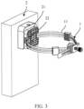
FIG. 3 is a schematic diagram of a structure of an electronic device according to an embodiment of this application; -
FIG. 4 is a schematic diagram of a structure when an electronic device is held onto a rod body according to an embodiment of this application; -
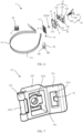
FIG. 5 is a three-dimensional diagram of a first type of hoop according to an embodiment of this application; -
FIG. 6 is an exploded diagram of the hoop shown inFIG. 5 ; -
FIG. 7 is a three-dimensional diagram of a strap buckle in the hoop shown inFIG. 5 ; -
FIG. 8 is a cross-sectional view of an assembly structure of a buckle body, a support member, a driving member, and an elastic pad in the hoop shown inFIG. 5 ; -
FIG. 9 is a three-dimensional diagram of a second type of hoop according to an embodiment of this application; -
FIG. 10 is an exploded diagram of the hoop shown inFIG. 9 ; -
FIG. 11 is a three-dimensional diagram of a strap buckle in the hoop shown inFIG. 9 ; and -
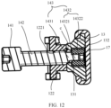
FIG. 12 is a cross-sectional view of an assembly structure of a buckle body, a support member, a driving member, and an elastic pad in the hoop shown inFIG. 9 . - Electronic devices such as an outdoor wireless router and a road surveillance camera are widely deployed in outdoor scenarios to implement wireless sharing, traffic violation capture, and traffic flow monitoring within a specific range. Specifically, the electronic devices may be fastened on existing rod bodies in outdoor scenarios, to reduce deployment costs of the electronic devices. For example, the electronic devices may be fastened on existing rod bodies such as a lamp post, a railing, a fence, and a downpipe. To make weights of the existing rod bodies (for example, a railing and a fence) light, or to make fluid media capable of being transmitted or electrical connection cables capable of being deployed inside the existing rod bodies (for example, a downpipe and a lamp post), the existing rod bodies usually have hollow structures with small wall thicknesses. If the electronic devices are connected to the existing rod bodies by using threaded connectors (for example, a bolt and a screw), holes need to be drilled on the rod bodies. Consequently, liquid media in the rod bodies leak, and structural strength of the rod bodies is greatly reduced. In addition, because the wall thicknesses of the existing rod bodies are small, threaded fitting sizes between the threaded connectors and the existing rod bodies are small, and the electronic devices cannot be securely connected to the rod bodies. If the electronic devices are connected to the existing rod bodies through welding, heat generated during welding is prone to damage the electronic devices. Moreover, the electronic devices are in line contact with the existing rod bodies, a welding area is small, an operation is difficult, and welding strength is low.
- To avoid the foregoing problems, an electronic device may be fastened on an existing rod body by using a hoop. The hoop includes a strap and a strap buckle, the strap is provided with a plurality of fastening holes along a length direction, one end of the strap is connected to the strap buckle, and the strap buckle is capable of being fastened to any one of the fastening holes, so that the strap is held onto an existing rod body. The electronic device is disposed on a part that is of the strap and that is held onto the existing rod body, so that the electronic device is fastened on the existing rod body. However, because there is a specific spacing between two adjacent fastening holes, a scope of rod bodies to which the hoop is applicable is limited. The hoop is not tightly held onto rod bodies of some diameters when being fastened on the rod bodies, resulting in a poor fastening effect.
- In view of this, some embodiments of this application provide an electronic device (as shown in
FIG. 3 ), including anelectronic device body 2 and ahoop 1. Theelectronic device body 2 includes but is not limited to an outdoor wireless router or a road surveillance camera. In some embodiments, as shown inFIG. 3 , theelectronic device body 2 is an outdoor wireless router. - Some embodiments of this application provide a hoop 1 (as shown in
FIG. 5 orFIG. 9 ). Thehoop 1 includes astrap 11, astrap buckle 12, asupport member 13, and a drivingmember 14. Thestrap 11 is provided with a plurality offastening holes 111 in a length direction. Thestrap buckle 12 includes abuckle head 121, abuckle body 122, and abuckle tail 123, thebuckle head 121 and thebuckle tail 123 are respectively located on two sides of thebuckle body 122 and are connected to thebuckle body 122, thebuckle tail 123 is connected to one end of thestrap 11, and thebuckle head 121 is capable of being fastened to any one of the fastening holes 111, so that thestrap 11 is held onto an existing rod body. Thesupport member 13 is located on a side that is of thebuckle body 122 and that is configured to face the existing rod body, the drivingmember 14 is connected between thesupport member 13 and thebuckle body 122, and the drivingmember 14 is configured to drive thesupport member 13 to move in a direction close to or away from thebuckle body 122. - As shown in
FIG. 3 , theelectronic device body 2 includes abase 21, thebase 21 is provided with a third throughhole 22, and theelectronic device body 2 is disposed on thestrap 11 of thehoop 1 through the third throughhole 22. - In the hoop provided in this embodiment of this application, as shown in
FIG. 5 orFIG. 9 , thehoop 1 includes thestrap 11 and thestrap buckle 12, thestrap 11 is provided with the plurality offastening holes 111 in the length direction, thestrap buckle 12 includes thebuckle head 121, thebuckle body 122, and thebuckle tail 123, thebuckle head 121 and thebuckle tail 123 are respectively located on the two sides of thebuckle body 122 and are connected to thebuckle body 122, thebuckle tail 123 is connected to one end of thestrap 11, and thebuckle head 121 is capable of being fastened to any one of the fastening holes 111, so that thestrap 11 is held onto the existing rod body. In addition, thehoop 1 includes thesupport member 13 and the drivingmember 14, thesupport member 13 is located on the side that is of thebuckle body 122 and that is configured to face the existing rod body, the drivingmember 14 is connected between thesupport member 13 and thebuckle body 122, and the drivingmember 14 is configured to drive thesupport member 13 to move in the direction close to or away from thebuckle body 122. Therefore, by fastening thebuckle head 121 todifferent fastening holes 111, thehoop 1 carrying the electronic device can be directly held tightly ontorod bodies 100 with a plurality of cross-sectional sizes defined by the plurality of fastening holes 111 (as shown inFIG. 4 ). When a cross-sectional size of a rod body is different from any one of the plurality of cross-sectional sizes, without changing a spacing between two adjacent fastening holes 111 on thestrap 11, thebuckle body 122 may be used as a reference after thestrap 11 is held onto therod body 100 by using thestrap buckle 12. The drivingmember 14 drives thesupport member 13 to move in the direction away from thebuckle body 122, so that thesupport member 13 presses therod body 100, and thestrap 11 is tightly held onto therod body 100. In this way, thehoop 1 can be tightly held onto the rod body with the cross-sectional size other than the plurality of cross-sectional sizes, thereby increasing a scope of rod bodies to which thehoop 1 is applicable. - Because the
hoop 1 used in the electronic device in this embodiment of this application is the same as thehoop 1 according to the foregoing technical solutions, the twohoops 1 can resolve a same technical problem and achieve a same expected effect. - In this embodiment of this application, a maximum travel of the driving
member 14 for driving thesupport member 13 to move may be 1 mm, 2 mm, 3 mm, or the like. This is not specifically limited herein. In some embodiments, the maximum travel of the drivingmember 14 for driving thesupport member 13 to move needs to be greater than or equal to a distance between any two adjacent fastening holes on thestrap 11. In this way, thehoop 1 can be tightly held onto a rod body with a cross-sectional size between two cross-sectional sizes defined by any two adjacent fastening holes on thestrap 11, thereby increasing a scope of rod bodies to which the hoop provided in this embodiment of this application is applicable. - A material of the
strap 11 includes but is not limited to metal, plastic, or gauze. In some embodiments, the material of thestrap 11 is 316 stainless steel. 316 stainless steel has high tensile strength and is resistant to corrosion and a high temperature, and a lifespan of thestrap 11 can be prolonged. - A thickness of the
strap 11 includes but is not limited to 1.2 mm, 1.0 mm, 0.8 mm, or 0.6 mm. In some embodiments, the thickness of thestrap 11 is 0.2 mm to 0.4 mm. In this way, the thickness of thestrap 11 is small, a minimum bending radius of thestrap 11 is small, and thestrap 11 can be tightly held onto a rod body whose cross section is rectangular, triangular, prismatic, or the like. - The
buckle tail 123 may be connected to one end of thestrap 11 through welding, riveting, or the like. This is not specifically limited herein. In some embodiments, as shown inFIG. 7 orFIG. 11 , thebuckle tail 123 includes arotating shaft 1231, and two ends of therotating shaft 1231 are connected to thebuckle body 122. As shown inFIG. 5 orFIG. 9 , one end of thestrap 11 winds around therotating shaft 1231 and is then bent reversely, and is fixedly connected to a part that is of thestrap 11 and that does not wind around therotating shaft 1231, so that thestrap 11 can rotate around therotating shaft 1231. This facilitates adjustment of an angle of thestrap 11 relative to thestrap buckle 12, so that thestrap 11 fits in with a surface of the to-be-held rod body, so as to be tightly held onto the to-be-held rod body. In some embodiments, the part that is of thestrap 11 and that winds around therotating shaft 1231 and the part that is of thestrap 11 and that does not wind around therotating shaft 1231 are fixedly connected to each other by using at least onerivet 15. Surface flatness that is present after riveting is performed by using therivet 15 is desirable, and no sharp protrusion appears. Therefore, the to-be-held rod body or installation personnel are not scratched. - A shape of the
support member 13 includes but is not limited to a plate shape, a block shape, or a disk shape. In some embodiments, as shown inFIG. 6 , the shape of thesupport member 13 is a plate shape. In some other embodiments, as shown inFIG. 10 , the shape of thesupport member 13 is a disk shape. - The driving
member 14 includes but is not limited to a linear actuator, a hydraulic cylinder, or a screw rod. In some embodiments, as shown inFIG. 6 orFIG. 10 , the drivingmember 14 is a hand torsion bar, and the hand torsion bar includes ahand torsion part 141, ascrew rod part 142, and a connectingpart 143 that are successively connected in a length direction. As shown inFIG. 7 orFIG. 11 , thebuckle body 122 is provided with a threadedhole 1221. As shown inFIG. 8 orFIG. 12 , thehand torsion part 141 is located on a side that is of thebuckle body 122 and that is away from thesupport member 13, thescrew rod part 142 is screwed into the threadedhole 1221, and the connectingpart 143 is connected to thesupport member 13. In this way, thehand torsion part 141 can be operated to drive thesupport member 13 to move in the direction close to or away from thebuckle body 122. Such a drivingmember 14 has a simple structure, a small footprint, and low costs. - The connecting
part 143 may be fixedly or rotatably connected to thesupport member 13. This is not specifically limited herein. In some embodiments, as shown inFIG. 8 orFIG. 12 , the connectingpart 143 may be rotatably connected to thesupport member 13, and an axis of rotation between the connectingpart 143 and thesupport member 13 is collinear with a central axis of thescrew rod part 142. In this way, thesupport member 13 is not fastened to the connectingpart 143, and when the hand torsion bar is rotated to drive thesupport member 13 to press the rod body, thesupport member 13 is not rotated together with the hand torsion bar under the friction action of the rod body. This can avoid friction and wear between thesupport member 13 and the rod body caused when the rod body is pressed. - To implement the rotatable connection between the connecting
part 143 and thesupport member 13, in some embodiments, as shown inFIG. 8 orFIG. 12 , the connectingpart 143 includes arotating shaft 1431 and a stoppingstructure 1432, one end of therotating shaft 1431 is fastened to thescrew rod part 142, a central axis of therotating shaft 1431 is collinear with the central axis of thescrew rod part 142, a diameter of therotating shaft 1431 is less than a diameter of thescrew rod part 142, and a shaft shoulder c is formed between therotating shaft 1431 and thescrew rod part 142; and thesupport member 13 is provided with a connectinghole 131, thesupport member 13 is disposed on therotating shaft 1431 through the connectinghole 131, the shaft shoulder c stops at one side of thesupport member 13, the stoppingstructure 1432 is connected to the other end of therotating shaft 1431, and the stoppingstructure 1432 stops at the other side of thesupport member 13. Such a structure is simple and is easy to implement. - In some embodiments, as shown in
FIG. 8 orFIG. 12 , a location, corresponding to the connectinghole 131, of a surface that is of thesupport member 13 and that is away from thebuckle body 122 is provided with a sinkinggroove 132, and the stoppingstructure 1432 is located in the sinkinggroove 132. In this way, the stoppingstructure 1432 does not protrude from the surface that is of thesupport member 13 and that is away from thebuckle body 122, the stoppingstructure 1432 is not in contact with the rod body, and the stoppingstructure 1432 does not damage the rod body when rotating together with thescrew rod part 142. - In some embodiments, as shown in
FIG. 8 orFIG. 12 , the stoppingstructure 1432 includes ascrew rod 14321 and anut 14322, thescrew rod 14321 is connected to therotating shaft 1431, and thenut 14322 is screwed onto thescrew rod 14321. - In some embodiments, as shown in
FIG. 6 , a limitingstructure 19 is disposed between thesupport member 13 and thebuckle body 122, and the limitingstructure 19 allows thesupport member 13 to move in the direction close to or away from thebuckle body 122 and prevents thesupport member 13 from rotating relative to thebuckle body 122. In this way, when the hand torsion bar is rotated, the limitingstructure 19 can prevent thesupport member 13 from rotating relative to thebuckle body 122. This avoids friction between thesupport member 13 and the rod body caused when the rod body is pressed. - There are a plurality of structural forms for the limiting
structure 19. This is not specifically limited herein. In some embodiments, as shown inFIG. 6 , the limitingstructure 19 includes a square limitinghole 191 and a limitingprotrusion 192, one of the square limitinghole 191 and the limitingprotrusion 192 is disposed on thebuckle body 122, the other one of the square limitinghole 191 and the limitingprotrusion 192 is disposed on thesupport member 13, an axial direction of the square limitinghole 191 is the same as that of thescrew rod part 142, the limitingprotrusion 192 is accommodated in the square limitinghole 191 and is capable of sliding along the axial direction of the square limitinghole 191, the limitingprotrusion 192 has a first side surface m and a second side surface n, and the first side surface m and the second side surface n respectively fit in with two opposite inner walls of the square limitinghole 191. By making the limitingprotrusion 192 slide along the axial direction of the square limitinghole 191, the limitingstructure 19 allows thesupport member 13 to move in the direction close to or away from thebuckle body 122; and by making the two inner side surfaces of the square limitinghole 191 fit in with the first side surface m and the second side surface n of the limitingprotrusion 192, the limitingstructure 19 prevents the limitingprotrusion 192 from rotating in the square limitinghole 191, to prevent thesupport member 13 from rotating relative to thebuckle body 122. Such a limitingstructure 19 is simple and is easy to implement. - To fasten the
buckle head 121 to thefastening hole 111, in some embodiments, as shown inFIG. 7 orFIG. 11 , astrap hole 1211 is disposed on thebuckle head 121, thestrap hole 1211 allows thestrap 11 to pass through, a hook-up 16 is disposed on an inner wall of thestrap hole 1211, and thefastening hole 111 is capable of being hung on the hook-up 16. In this way, thestrap 11 passes through thestrap hole 1211, and thebuckle head 121 is fastened to thefastening hole 111 by hanging thefastening hole 111 on the hook-up 16. Such a structure is simple and is convenient to operate. - In the foregoing embodiment, the hook-
up 16 may be disposed on an inner wall of one end that is of thestrap hole 1211 and that is away from thebuckle body 122, may be disposed on an inner wall of one end that is of thestrap hole 1211 and that is close to thebuckle body 122, or may be disposed on inner walls of the other two ends of thestrap hole 1211. This is not specifically limited herein. In some embodiments, as shown inFIG. 7 orFIG. 11 , the hook-up 16 is disposed on the inner wall of one end that is of thestrap hole 1211 and that is away from thebuckle body 122. In this way, after thestrap 11 passes through thestrap hole 1211 and thefastening hole 111 is hung on the hook-up 16, thestrap 11 is bent reversely, to prevent thefastening hole 111 from being released from the hook-up 16. This enables a convenient operation and desirable appearance neatness. - A material of the
support member 13 includes but is not limited to metal, plastic, silica gel, or rubber. Thesupport member 13 may be entirely made of a rigid material, or may be entirely made of an elastic material, or may be partially made of a rigid material and partially made of an elastic material. This is not specifically limited herein. - In some embodiments, as shown in
FIG. 6 orFIG. 10 , thehoop 1 further includes anelastic pad 17. Theelastic pad 17 is disposed at least at an end that is of thesupport member 13 and that is away from thebuckle body 122. In this way, when the drivingmember 14 drives thesupport member 13 to move in the direction away from thebuckle body 122 to press the rod body, theelastic pad 17 comes into contact with the rod body. This avoids compressive deformation of the rod body. - In the foregoing embodiment, that the
elastic pad 17 is disposed at least at an end that is of thesupport member 13 and that is away from thebuckle body 122 means: Theelastic pad 17 may be disposed only at the end that is of thesupport member 13 and that is away from thebuckle body 122, or may be disposed at the end that is of thesupport member 13 and that is away from thebuckle body 122 and disposed at another part of thesupport member 13. This is not specifically limited herein. In some embodiments, as shown inFIG. 8 , theelastic pad 17 is disposed only at the end that is of thesupport member 13 and that is away from thebuckle body 122. In some other embodiments, as shown inFIG. 12 , theelastic pad 17 is disposed at the end that is of thesupport member 13 and that is away from thebuckle body 122 and disposed on a side surface of thesupport member 13. That theelastic pad 17 is disposed at the end that is of thesupport member 13 and that is away from thebuckle body 122 specifically means: Theelastic pad 17 may cover an entire end surface of the end that is of thesupport member 13 and that is away from the buckle body 122 (as shown inFIG. 8 orFIG. 12 ), or cover only a partial end face of the end that is of thesupport member 13 and that is away from thebuckle body 122. For example, theelastic pad 17 covers only an edge region of the end face of the end that is of thesupport member 13 and that is away from thebuckle body 122. This is not specifically limited herein. - In some embodiments, as shown in
FIG. 6 , a surface that is of theelastic pad 17 and that is away from thebuckle body 122 is provided with an anti-slide structure a. In this way, when thehoop 1 in this embodiment of this application is tightly held onto the rod body, the anti-slide structure a on theelastic pad 17 comes into contact with the rod body. This can prevent thehoop 1 from sliding down along the rod body. - There are a plurality of structural forms for the anti-slide structure a. This is not specifically limited herein. In some embodiments, as shown in
FIG. 6 , the anti-slide structure a is a plurality of ribs uniformly disposed on the surface that is of theelastic pad 17 and that is away from thebuckle body 122, and the plurality of ribs are arranged intersecting each other. - In some embodiments, the surface that is of the
elastic pad 17 and that is away from thebuckle body 122 is a first profiling surface, and the first profiling surface is adapted to the surface of the rod body. In this way, when thehoop 1 in this embodiment of this application is tightly held onto the rod body, the first profiling surface fits in with the surface of the rod body, and a fitting area is large, so that a pressing force between theelastic pad 17 and the rod body acts on a larger surface. This avoids compressive deformation of the rod body. - In some embodiments, as shown in
FIG. 5 orFIG. 9 , thehoop 1 further includes at least onestrap accommodation member 18. As shown inFIG. 6 , eachstrap accommodation member 18 is provided with first throughholes 181 and second throughholes 182, thestrap accommodation member 18 is disposed, through the first throughholes 181, on a part that is of thestrap 11 and that is configured to hold onto the existing rod body, and a part that is of thestrap 11 and that is not configured to hold onto the existing rod body is capable of being disposed through the second throughholes 182. In this way, thestrap accommodation member 18 accommodates the part that is of thestrap 11 and that is not configured to hold onto the existing rod body, appearance neatness of thehoop 1 that is present after thehoop 1 is fastened on the rod body is ensured. In addition, thestrap accommodation member 18 can slide along the length direction of thestrap 11, to adjust a location of thestrap accommodation member 18, so that thestrap accommodation member 18 can accommodate parts of the strap that have different lengths and that are not configured to hold onto the existing rod body. - There may be one, two, three, or more
strap accommodation members 18. This is not specifically limited herein. In some embodiments, as shown inFIG. 5 orFIG. 9 , there are twostrap accommodation members 18. In this way, thestrap accommodation members 18 can accommodate parts of the strap that have a large length and that are not configured to hold onto the existing rod body, and the quantity of thestrap accommodation members 18 is relatively small, so that structural complexity and costs of thehoop 1 can be reduced. - The first through
holes 181 and the second throughholes 182 may be arranged side by side (that is, an axial direction of the first throughholes 181 and an axial direction of the second throughholes 182 are parallel to each other), may be perpendicular to each other (that is, the axial direction of the first throughholes 181 and the axial direction of the second throughholes 182 are perpendicular to each other), or may be in another orientation relationship. This is not specifically limited herein. In some embodiments, as shown inFIG. 6 , the first throughholes 181 and the second throughholes 182 are arranged side by side, and the first throughholes 181 and the second throughholes 182 are arranged along a thickness direction of thestrap 11. In this way, when thestrap 11 winds around the rod body, thebuckle head 121 is fastened to afastening hole 111 so that thestrap 11 is held onto the rod body, and the part that is of thestrap 11 and that is not configured to hold onto the existing rod body is disposed through the second throughholes 182, the part that is of thestrap 11 and that is not configured to hold onto the existing rod body partially overlaps the part that is of thestrap 11 and that is held onto the rod body. This enables desirable appearance neatness. - The first through
holes 181 and the second throughholes 182 may be independent of each other, or may penetrate through each other. This is not specifically limited herein. In some embodiments, as shown inFIG. 6 , the first throughholes 181 and the second throughholes 182 are independent of each other, to avoid friction between the part that is of thestrap 11 and that is disposed through the first throughholes 181 and the part that is of thestrap 11 and that is disposed through the second throughholes 182. In some other embodiments, the first throughholes 181 and the second throughholes 182 penetrate through each other. In this way, only one through hole needs to be formed on thestrap accommodation member 18. Therefore, thestrap accommodation member 18 has a simple structure and is easy to fabricate. - In some embodiments, as shown in
FIG. 6 , a surface that is of thestrap accommodation member 18 and that is configured to fit in with the existing rod body is provided with an anti-slide structure b. In this way, when thehoop 1 in this embodiment of this application is tightly held onto the rod body, the anti-slide structure b on thestrap accommodation member 18 comes into contact with the rod body. This can prevent thehoop 1 from sliding down along the rod body. - There are a plurality of structural forms for the anti-slide structure b. This is not specifically limited herein. In some embodiments, as shown in
FIG. 6 , the anti-slide structure b is a plurality of ribs uniformly disposed on the inner surface of thestrap accommodation member 18, and the plurality of ribs are arranged intersecting each other. - In some embodiments, the surface that is of the
strap accommodation member 18 and that is configured to fit in with the existing rod body is a second profiling surface, and the second profiling surface is adapted to the surface of the rod body. In this way, when thehoop 1 in this embodiment of this application is tightly held onto the rod body, the second profiling surface fits in with the surface of the rod body, and a fitting area is large, so that a pressing force between thestrap accommodation member 18 and the rod body acts on a larger surface. This avoids damage to thestrap accommodation member 18 and the rod body during mutual pressing - A material of the
strap accommodation member 18 includes but is not limited to plastic, silica gel, rubber, or metal. In some embodiments, the material of thestrap accommodation member 18 is silica gel. Silica gel has high toughness and can be prevented from being scratched by thestrap 11 when sliding along thestrap 11. - In some embodiments, the electronic device body is provided with a third through hole, and the electronic device body is disposed on the
strap 11 through the third through hole. In this way, the electronic device body may slide along thestrap 11, to adjust a location of the electronic device body on thestrap 11. - In the descriptions of this specification, the specific features, structures, materials, or characteristics may be combined in a proper manner in any one or more of embodiments or examples.
- Finally, it should be noted that the foregoing embodiments are merely intended to describe the technical solutions of this application, but not to limit this application. Although this application is described in detail with reference to the foregoing embodiments, persons of ordinary skill in the art should understand that they may still make modifications to the technical solutions described in the foregoing embodiments or make equivalent replacements to some technical features thereof, without departing from the scope of the technical solutions of embodiments of this application as defined in the appended claims.
Claims (13)
- A hoop (1), comprising a strap (11), a strap buckle (12), a support member (13), and a driving member (14), whereinthe strap (11) is provided with a plurality of fastening holes (111) in a length direction;the strap buckle (12) comprises a buckle head (121), a buckle body (122), and a buckle tail (123), the buckle head (121) and the buckle tail (123) are respectively located on two sides of the buckle body (122) and are connected to the buckle body (122), the buckle tail (123) is connected to one end of the strap (11), and the buckle head (121) is capable of being fastened to any one of the fastening holes (111), so that the strap (11) can be held, in use, onto an existing rod body (100); andthe support member (13) is located on a side that is of the buckle body (122) facing in use the existing rod body (100),characterized in that the driving member (14) is connected between the support member (13) and the buckle body (122), and the driving member (14) is configured to drive the support member (13) to move in a direction close to or away from the buckle body (122).
- The hoop according to claim 1, wherein the driving member (14) is a hand torsion bar, and the hand torsion bar comprises a hand torsion part (141), a screw rod part (142), and a connecting part (143) that are successively connected in a length direction; and
the buckle body (122) is provided with a threaded hole (1221), the hand torsion part (141) is located on a side that is of the buckle body (122) and that is away from the support member (13), the screw rod part (142) is screwed into the threaded hole (1221), and the connecting part (143) is connected to the support member (13). - The hoop according to claim 2, wherein the connecting part (143) is rotatably connected to the support member (13), and an axis of rotation between the connecting part (143) and the support member (13) is collinear with a central axis of the screw rod part (142).
- The hoop according to claim 3, wherein a limiting structure (19) is disposed between the support member (13) and the buckle body (122), and the limiting structure (19) allows the support member (13) to move in the direction close to or away from the buckle body (122) and prevents the support member (13) from rotating relative to the buckle body (122).
- The hoop according to claim 4, wherein the limiting structure (19) comprises a square limiting hole (191) and a limiting protrusion (192), one of the square limiting hole (191) and the limiting protrusion (192) is disposed on the buckle body (122), the other one of the square limiting hole (191) and the limiting protrusion (192) is disposed on the support member (13), an axial direction of the square limiting hole (191) is the same as that of the screw rod part (142), the limiting protrusion (192) is accommodated in the square limiting hole (191) and is capable of sliding along the axial direction of the square limiting hole (191), the limiting protrusion (192) has a first side surface (m) and a second side surface (n), and the first side surface (m) and the second side surface (n) respectively fit in with two opposite inner walls of the square limiting hole (191).
- The hoop according to any one of claims 1 to 5, wherein a strap hole (1211) is disposed on the buckle head (121), the strap hole (1211) allows the strap (11) to pass through, a hook-up (16) is disposed on an inner wall of the strap hole (1211), and the fastening hole (111) is capable of being hung on the hook-up (16).
- The hoop according to any one of claims 1 to 6, further comprising an elastic pad (17), wherein the elastic pad (17) is disposed at least at an end that is of the support member (13) and that is away from the buckle body (122).
- The hoop according to claim 7, wherein a surface that is of the elastic pad (17) and that is away from the buckle body (122) is provided with an anti-slide structure.
- The hoop according to any one of claims 1 to 8, further comprising at least one strap accommodation member (18), each strap accommodation member (18) is provided with first through holes (181) and second through holes (182), the first through holes (181) and the second through holes (182) are arranged side by side, the strap accommodation member (18) is disposed, through the first through holes (181), on a part that is of the strap (11) and that is configured to hold onto the existing rod body (100), and a part that is of the strap (11) and that is not configured to hold onto the existing rod body (100) is capable of being disposed through the second through holes (182).
- The hoop according to claim 9, wherein a surface that is of the strap accommodation member (18) and that is configured to fit in with the existing rod body (100) is provided with an anti-slide structure.
- The hoop according to any one of claims 1 to 10, wherein a thickness of the strap (11) is 0.2 mm to 0.4 mm.
- An electronic device, comprising an electronic device body (2) and the hoop (1) according to any one of claims 1 to 11, wherein a base (21) of the electronic device body (2) is provided with a third through hole (22), and the electronic device body (2) is disposed on the strap (11) through the third through hole (22).
- The electronic device according to claim 12, wherein the electronic device body (2) is an outdoor wireless router.
Applications Claiming Priority (2)
| Application Number | Priority Date | Filing Date | Title |
|---|---|---|---|
| CN201911036924.6A CN112747225A (en) | 2019-10-29 | 2019-10-29 | Staple bolt and electronic equipment |
| PCT/CN2020/104865 WO2021082559A1 (en) | 2019-10-29 | 2020-07-27 | Hoop and electronic device |
Publications (3)
| Publication Number | Publication Date |
|---|---|
| EP4040033A1 EP4040033A1 (en) | 2022-08-10 |
| EP4040033A4 EP4040033A4 (en) | 2022-12-07 |
| EP4040033B1 true EP4040033B1 (en) | 2025-06-25 |
Family
ID=75641650
Family Applications (1)
| Application Number | Title | Priority Date | Filing Date |
|---|---|---|---|
| EP20880474.0A Active EP4040033B1 (en) | 2019-10-29 | 2020-07-27 | Hoop and electronic device |
Country Status (3)
| Country | Link |
|---|---|
| EP (1) | EP4040033B1 (en) |
| CN (1) | CN112747225A (en) |
| WO (1) | WO2021082559A1 (en) |
Families Citing this family (12)
| Publication number | Priority date | Publication date | Assignee | Title |
|---|---|---|---|---|
| CN113533814B (en) * | 2021-08-30 | 2024-03-29 | 广东电网有限责任公司 | Ammeter fixing device and power metering box |
| FR3127033B1 (en) * | 2021-09-10 | 2023-08-18 | Sagemcom Broadband Sas | Clamping by constrained strap |
| EP4407792A4 (en) * | 2021-09-24 | 2025-10-08 | Kmw Inc | CLAMPING DEVICE FOR AN ANTENNA DEVICE |
| CN113914696A (en) * | 2021-10-22 | 2022-01-11 | 浙江德宝通讯科技股份有限公司 | Staple bolt and communication tower |
| TWI813525B (en) * | 2023-01-09 | 2023-08-21 | 啓碁科技股份有限公司 | Communication apparatus and bracket structure thereof |
| CN118361454B (en) * | 2023-01-19 | 2025-03-21 | 荣耀终端股份有限公司 | Sliding mechanism and electronic device |
| JP2024145605A (en) * | 2023-03-31 | 2024-10-15 | i-PRO株式会社 | Camera mounting parts |
| CN116530959B (en) * | 2023-04-11 | 2023-12-26 | 称意科技研发园(江苏)有限公司 | Intelligent wearing who possesses heart rate monitoring |
| CN116683164B (en) * | 2023-07-14 | 2023-12-29 | 人天通信集团有限公司 | Single-polarized panel antenna |
| US20250164035A1 (en) * | 2023-11-22 | 2025-05-22 | Honeywell Safety Products Usa, Inc. | Clamping device |
| CN117549063B (en) * | 2023-11-24 | 2024-06-14 | 天津市鹤鼎工贸有限公司 | Mounting device of hoop compensator |
| CN117839947B (en) * | 2024-03-08 | 2024-07-12 | 国网山东省电力公司安丘市供电公司 | A power supply accessory painting device |
Family Cites Families (12)
| Publication number | Priority date | Publication date | Assignee | Title |
|---|---|---|---|---|
| JPS60113810A (en) * | 1983-11-22 | 1985-06-20 | 株式会社高木製作所 | Worm band clamp tool |
| DE3607359A1 (en) * | 1985-03-07 | 1986-09-11 | Erich Schlemper Gmbh & Co Kg, 5620 Velbert | Bracing clamp |
| US20060191113A1 (en) * | 2005-02-28 | 2006-08-31 | Chin Shih C | Fastener for fastening tubular objects |
| CN201916298U (en) * | 2010-07-07 | 2011-08-03 | 李一品 | Locking device of hoop |
| ITTV20120060A1 (en) * | 2012-04-16 | 2013-10-17 | Walmec Spa | "DEVICE FOR UNIVERSAL ELASTIC BAND, ADJUSTABLE AND REMOVABLE FOR FIXING PORTABLE ELECTRONIC EQUIPMENT TO A VEHICLE". |
| GB201322367D0 (en) * | 2013-12-18 | 2014-02-05 | Mcgriskin Ideas Ltd | Spacer block system |
| CN105757075B (en) * | 2016-04-21 | 2017-11-07 | 西安中科微精光子制造科技有限公司 | A kind of circular orientation device |
| CN206890034U (en) * | 2017-05-28 | 2018-01-16 | 福建西河卫浴科技有限公司 | A kind of fixed structure and control box for being easy to fast assembling-disassembling |
| CN207261385U (en) * | 2017-09-04 | 2018-04-20 | 余姚市恒威卡箍有限公司 | Anti-loose scroll drive type clip |
| JP2019113134A (en) * | 2017-12-25 | 2019-07-11 | 大和化成工業株式会社 | Binding band |
| JP6973707B2 (en) * | 2018-01-23 | 2021-12-01 | 株式会社アサヒ | Fixing device |
| CN211952140U (en) * | 2019-10-29 | 2020-11-17 | 华为技术有限公司 | A hoop and electronic device |
-
2019
- 2019-10-29 CN CN201911036924.6A patent/CN112747225A/en active Pending
-
2020
- 2020-07-27 WO PCT/CN2020/104865 patent/WO2021082559A1/en not_active Ceased
- 2020-07-27 EP EP20880474.0A patent/EP4040033B1/en active Active
Also Published As
| Publication number | Publication date |
|---|---|
| EP4040033A1 (en) | 2022-08-10 |
| WO2021082559A1 (en) | 2021-05-06 |
| EP4040033A4 (en) | 2022-12-07 |
| CN112747225A (en) | 2021-05-04 |
Similar Documents
| Publication | Publication Date | Title |
|---|---|---|
| EP4040033A1 (en) | Hoop and electronic device | |
| US12241619B2 (en) | Tiltable luminaire joint | |
| CN105075042B (en) | Cable clamping device | |
| US20210095476A1 (en) | Roof mounting bracket | |
| EP3019754B1 (en) | Clamp for standing seam | |
| CA2920170C (en) | Chain load binder | |
| US20100314817A1 (en) | Clamp apparatus | |
| US9151069B2 (en) | Spool-mounted coiled structural extending member | |
| US7628430B2 (en) | Hurricane strut for double entrance doors | |
| KR20030068149A (en) | Universal Support and Vibration Isolator | |
| JP2018149263A (en) | Adjustable mounting plate assembly | |
| CN201173248Y (en) | Pivotal device | |
| US20220140465A1 (en) | Antenna mounting assembly of base station antenna | |
| US20100175271A1 (en) | Compression Indicator | |
| US8282143B2 (en) | Positioning device | |
| EP3591220B1 (en) | Wind turbine | |
| US8625265B2 (en) | Flat panel display | |
| CN204213119U (en) | Belt securing means | |
| CN101267862B (en) | Energy absorber | |
| EP1683975B1 (en) | Apparatus for connecting support bars of a sport equipment | |
| CN105465115B (en) | Belt type fastening device | |
| CN211258186U (en) | Blood analyzer and damping hinge assembly thereof | |
| CN207394272U (en) | Support fixed structure | |
| CN216380948U (en) | Telescopic brace rod | |
| CN222928049U (en) | Communication cable connection structure |
Legal Events
| Date | Code | Title | Description |
|---|---|---|---|
| STAA | Information on the status of an ep patent application or granted ep patent |
Free format text: STATUS: THE INTERNATIONAL PUBLICATION HAS BEEN MADE |
|
| PUAI | Public reference made under article 153(3) epc to a published international application that has entered the european phase |
Free format text: ORIGINAL CODE: 0009012 |
|
| STAA | Information on the status of an ep patent application or granted ep patent |
Free format text: STATUS: REQUEST FOR EXAMINATION WAS MADE |
|
| 17P | Request for examination filed |
Effective date: 20220503 |
|
| AK | Designated contracting states |
Kind code of ref document: A1 Designated state(s): AL AT BE BG CH CY CZ DE DK EE ES FI FR GB GR HR HU IE IS IT LI LT LU LV MC MK MT NL NO PL PT RO RS SE SI SK SM TR |
|
| A4 | Supplementary search report drawn up and despatched |
Effective date: 20221108 |
|
| RIC1 | Information provided on ipc code assigned before grant |
Ipc: H01Q 1/12 20060101ALN20221102BHEP Ipc: F16B 2/08 20060101ALI20221102BHEP Ipc: F16M 13/02 20060101AFI20221102BHEP |
|
| DAV | Request for validation of the european patent (deleted) | ||
| DAX | Request for extension of the european patent (deleted) | ||
| GRAP | Despatch of communication of intention to grant a patent |
Free format text: ORIGINAL CODE: EPIDOSNIGR1 |
|
| STAA | Information on the status of an ep patent application or granted ep patent |
Free format text: STATUS: GRANT OF PATENT IS INTENDED |
|
| RIC1 | Information provided on ipc code assigned before grant |
Ipc: H01Q 1/12 20060101ALN20250205BHEP Ipc: F16B 2/08 20060101ALI20250205BHEP Ipc: F16M 13/02 20060101AFI20250205BHEP |
|
| RIC1 | Information provided on ipc code assigned before grant |
Ipc: H01Q 1/12 20060101ALN20250214BHEP Ipc: F16B 2/08 20060101ALI20250214BHEP Ipc: F16M 13/02 20060101AFI20250214BHEP |
|
| INTG | Intention to grant announced |
Effective date: 20250228 |
|
| GRAS | Grant fee paid |
Free format text: ORIGINAL CODE: EPIDOSNIGR3 |
|
| GRAA | (expected) grant |
Free format text: ORIGINAL CODE: 0009210 |
|
| STAA | Information on the status of an ep patent application or granted ep patent |
Free format text: STATUS: THE PATENT HAS BEEN GRANTED |
|
| AK | Designated contracting states |
Kind code of ref document: B1 Designated state(s): AL AT BE BG CH CY CZ DE DK EE ES FI FR GB GR HR HU IE IS IT LI LT LU LV MC MK MT NL NO PL PT RO RS SE SI SK SM TR |
|
| REG | Reference to a national code |
Ref country code: GB Ref legal event code: FG4D |
|
| REG | Reference to a national code |
Ref country code: CH Ref legal event code: EP |
|
| REG | Reference to a national code |
Ref country code: CH Ref legal event code: EP |
|
| REG | Reference to a national code |
Ref country code: IE Ref legal event code: FG4D |
|
| REG | Reference to a national code |
Ref country code: DE Ref legal event code: R096 Ref document number: 602020053516 Country of ref document: DE |
|
| PG25 | Lapsed in a contracting state [announced via postgrant information from national office to epo] |
Ref country code: FI Free format text: LAPSE BECAUSE OF FAILURE TO SUBMIT A TRANSLATION OF THE DESCRIPTION OR TO PAY THE FEE WITHIN THE PRESCRIBED TIME-LIMIT Effective date: 20250625 |
|
| PGFP | Annual fee paid to national office [announced via postgrant information from national office to epo] |
Ref country code: DE Payment date: 20250708 Year of fee payment: 6 |
|
| REG | Reference to a national code |
Ref country code: LT Ref legal event code: MG9D |
|
| PG25 | Lapsed in a contracting state [announced via postgrant information from national office to epo] |
Ref country code: NO Free format text: LAPSE BECAUSE OF FAILURE TO SUBMIT A TRANSLATION OF THE DESCRIPTION OR TO PAY THE FEE WITHIN THE PRESCRIBED TIME-LIMIT Effective date: 20250925 Ref country code: GR Free format text: LAPSE BECAUSE OF FAILURE TO SUBMIT A TRANSLATION OF THE DESCRIPTION OR TO PAY THE FEE WITHIN THE PRESCRIBED TIME-LIMIT Effective date: 20250926 |
|
| PG25 | Lapsed in a contracting state [announced via postgrant information from national office to epo] |
Ref country code: BG Free format text: LAPSE BECAUSE OF FAILURE TO SUBMIT A TRANSLATION OF THE DESCRIPTION OR TO PAY THE FEE WITHIN THE PRESCRIBED TIME-LIMIT Effective date: 20250625 |
|
| PGFP | Annual fee paid to national office [announced via postgrant information from national office to epo] |
Ref country code: GB Payment date: 20250710 Year of fee payment: 6 |
|
| PG25 | Lapsed in a contracting state [announced via postgrant information from national office to epo] |
Ref country code: HR Free format text: LAPSE BECAUSE OF FAILURE TO SUBMIT A TRANSLATION OF THE DESCRIPTION OR TO PAY THE FEE WITHIN THE PRESCRIBED TIME-LIMIT Effective date: 20250625 |
|
| PG25 | Lapsed in a contracting state [announced via postgrant information from national office to epo] |
Ref country code: RS Free format text: LAPSE BECAUSE OF FAILURE TO SUBMIT A TRANSLATION OF THE DESCRIPTION OR TO PAY THE FEE WITHIN THE PRESCRIBED TIME-LIMIT Effective date: 20250925 |
|
| PG25 | Lapsed in a contracting state [announced via postgrant information from national office to epo] |
Ref country code: LV Free format text: LAPSE BECAUSE OF FAILURE TO SUBMIT A TRANSLATION OF THE DESCRIPTION OR TO PAY THE FEE WITHIN THE PRESCRIBED TIME-LIMIT Effective date: 20250625 |
|
| REG | Reference to a national code |
Ref country code: NL Ref legal event code: MP Effective date: 20250625 |
|
| PG25 | Lapsed in a contracting state [announced via postgrant information from national office to epo] |
Ref country code: NL Free format text: LAPSE BECAUSE OF FAILURE TO SUBMIT A TRANSLATION OF THE DESCRIPTION OR TO PAY THE FEE WITHIN THE PRESCRIBED TIME-LIMIT Effective date: 20250625 |
|
| PG25 | Lapsed in a contracting state [announced via postgrant information from national office to epo] |
Ref country code: PT Free format text: LAPSE BECAUSE OF FAILURE TO SUBMIT A TRANSLATION OF THE DESCRIPTION OR TO PAY THE FEE WITHIN THE PRESCRIBED TIME-LIMIT Effective date: 20251027 |
|
| REG | Reference to a national code |
Ref country code: AT Ref legal event code: MK05 Ref document number: 1806746 Country of ref document: AT Kind code of ref document: T Effective date: 20250625 |
|
| PG25 | Lapsed in a contracting state [announced via postgrant information from national office to epo] |
Ref country code: IS Free format text: LAPSE BECAUSE OF FAILURE TO SUBMIT A TRANSLATION OF THE DESCRIPTION OR TO PAY THE FEE WITHIN THE PRESCRIBED TIME-LIMIT Effective date: 20251025 |
|
| PG25 | Lapsed in a contracting state [announced via postgrant information from national office to epo] |
Ref country code: AT Free format text: LAPSE BECAUSE OF FAILURE TO SUBMIT A TRANSLATION OF THE DESCRIPTION OR TO PAY THE FEE WITHIN THE PRESCRIBED TIME-LIMIT Effective date: 20250625 Ref country code: SM Free format text: LAPSE BECAUSE OF FAILURE TO SUBMIT A TRANSLATION OF THE DESCRIPTION OR TO PAY THE FEE WITHIN THE PRESCRIBED TIME-LIMIT Effective date: 20250625 |
|
| PG25 | Lapsed in a contracting state [announced via postgrant information from national office to epo] |
Ref country code: CZ Free format text: LAPSE BECAUSE OF FAILURE TO SUBMIT A TRANSLATION OF THE DESCRIPTION OR TO PAY THE FEE WITHIN THE PRESCRIBED TIME-LIMIT Effective date: 20250625 |
|
| PG25 | Lapsed in a contracting state [announced via postgrant information from national office to epo] |
Ref country code: PL Free format text: LAPSE BECAUSE OF FAILURE TO SUBMIT A TRANSLATION OF THE DESCRIPTION OR TO PAY THE FEE WITHIN THE PRESCRIBED TIME-LIMIT Effective date: 20250625 |
|
| PG25 | Lapsed in a contracting state [announced via postgrant information from national office to epo] |
Ref country code: EE Free format text: LAPSE BECAUSE OF FAILURE TO SUBMIT A TRANSLATION OF THE DESCRIPTION OR TO PAY THE FEE WITHIN THE PRESCRIBED TIME-LIMIT Effective date: 20250625 |
|
| PG25 | Lapsed in a contracting state [announced via postgrant information from national office to epo] |
Ref country code: SK Free format text: LAPSE BECAUSE OF FAILURE TO SUBMIT A TRANSLATION OF THE DESCRIPTION OR TO PAY THE FEE WITHIN THE PRESCRIBED TIME-LIMIT Effective date: 20250625 |
|
| PG25 | Lapsed in a contracting state [announced via postgrant information from national office to epo] |
Ref country code: ES Free format text: LAPSE BECAUSE OF FAILURE TO SUBMIT A TRANSLATION OF THE DESCRIPTION OR TO PAY THE FEE WITHIN THE PRESCRIBED TIME-LIMIT Effective date: 20250625 |
|
| REG | Reference to a national code |
Ref country code: CH Ref legal event code: H13 Free format text: ST27 STATUS EVENT CODE: U-0-0-H10-H13 (AS PROVIDED BY THE NATIONAL OFFICE) Effective date: 20260224 |
|
| PG25 | Lapsed in a contracting state [announced via postgrant information from national office to epo] |
Ref country code: RO Free format text: LAPSE BECAUSE OF FAILURE TO SUBMIT A TRANSLATION OF THE DESCRIPTION OR TO PAY THE FEE WITHIN THE PRESCRIBED TIME-LIMIT Effective date: 20250625 Ref country code: LU Free format text: LAPSE BECAUSE OF NON-PAYMENT OF DUE FEES Effective date: 20250727 |
|
| REG | Reference to a national code |
Ref country code: BE Ref legal event code: MM Effective date: 20250731 Ref country code: DE Ref legal event code: R097 Ref document number: 602020053516 Country of ref document: DE |
|
| PG25 | Lapsed in a contracting state [announced via postgrant information from national office to epo] |
Ref country code: MC Free format text: LAPSE BECAUSE OF FAILURE TO SUBMIT A TRANSLATION OF THE DESCRIPTION OR TO PAY THE FEE WITHIN THE PRESCRIBED TIME-LIMIT Effective date: 20250625 |
|
| PG25 | Lapsed in a contracting state [announced via postgrant information from national office to epo] |
Ref country code: DK Free format text: LAPSE BECAUSE OF FAILURE TO SUBMIT A TRANSLATION OF THE DESCRIPTION OR TO PAY THE FEE WITHIN THE PRESCRIBED TIME-LIMIT Effective date: 20250625 |
|
| PG25 | Lapsed in a contracting state [announced via postgrant information from national office to epo] |
Ref country code: BE Free format text: LAPSE BECAUSE OF NON-PAYMENT OF DUE FEES Effective date: 20250731 Ref country code: IT Free format text: LAPSE BECAUSE OF FAILURE TO SUBMIT A TRANSLATION OF THE DESCRIPTION OR TO PAY THE FEE WITHIN THE PRESCRIBED TIME-LIMIT Effective date: 20250625 |
|
| PG25 | Lapsed in a contracting state [announced via postgrant information from national office to epo] |
Ref country code: CH Free format text: LAPSE BECAUSE OF NON-PAYMENT OF DUE FEES Effective date: 20250731 |
|
| PLBE | No opposition filed within time limit |
Free format text: ORIGINAL CODE: 0009261 |
|
| STAA | Information on the status of an ep patent application or granted ep patent |
Free format text: STATUS: NO OPPOSITION FILED WITHIN TIME LIMIT |
|
| REG | Reference to a national code |
Ref country code: CH Ref legal event code: L10 Free format text: ST27 STATUS EVENT CODE: U-0-0-L10-L00 (AS PROVIDED BY THE NATIONAL OFFICE) Effective date: 20260507 |