EP4040019A1 - Réducteur mécanique - Google Patents
Réducteur mécanique Download PDFInfo
- Publication number
- EP4040019A1 EP4040019A1 EP22154887.8A EP22154887A EP4040019A1 EP 4040019 A1 EP4040019 A1 EP 4040019A1 EP 22154887 A EP22154887 A EP 22154887A EP 4040019 A1 EP4040019 A1 EP 4040019A1
- Authority
- EP
- European Patent Office
- Prior art keywords
- reducer
- planet carrier
- oil
- distributor
- axis
- Prior art date
- Legal status (The legal status is an assumption and is not a legal conclusion. Google has not performed a legal analysis and makes no representation as to the accuracy of the status listed.)
- Pending
Links
Images



Classifications
-
- F—MECHANICAL ENGINEERING; LIGHTING; HEATING; WEAPONS; BLASTING
- F16—ENGINEERING ELEMENTS AND UNITS; GENERAL MEASURES FOR PRODUCING AND MAINTAINING EFFECTIVE FUNCTIONING OF MACHINES OR INSTALLATIONS; THERMAL INSULATION IN GENERAL
- F16H—GEARING
- F16H57/00—General details of gearing
- F16H57/04—Features relating to lubrication or cooling or heating
- F16H57/0434—Features relating to lubrication or cooling or heating relating to lubrication supply, e.g. pumps; Pressure control
- F16H57/0435—Pressure control for supplying lubricant; Circuits or valves therefor
-
- F—MECHANICAL ENGINEERING; LIGHTING; HEATING; WEAPONS; BLASTING
- F01—MACHINES OR ENGINES IN GENERAL; ENGINE PLANTS IN GENERAL; STEAM ENGINES
- F01D—NON-POSITIVE DISPLACEMENT MACHINES OR ENGINES, e.g. STEAM TURBINES
- F01D25/00—Component parts, details, or accessories, not provided for in, or of interest apart from, other groups
- F01D25/18—Lubricating arrangements
-
- F—MECHANICAL ENGINEERING; LIGHTING; HEATING; WEAPONS; BLASTING
- F02—COMBUSTION ENGINES; HOT-GAS OR COMBUSTION-PRODUCT ENGINE PLANTS
- F02C—GAS-TURBINE PLANTS; AIR INTAKES FOR JET-PROPULSION PLANTS; CONTROLLING FUEL SUPPLY IN AIR-BREATHING JET-PROPULSION PLANTS
- F02C7/00—Features, components parts, details or accessories, not provided for in, or of interest apart form groups F02C1/00 - F02C6/00; Air intakes for jet-propulsion plants
- F02C7/06—Arrangements of bearings; Lubricating
-
- F—MECHANICAL ENGINEERING; LIGHTING; HEATING; WEAPONS; BLASTING
- F02—COMBUSTION ENGINES; HOT-GAS OR COMBUSTION-PRODUCT ENGINE PLANTS
- F02C—GAS-TURBINE PLANTS; AIR INTAKES FOR JET-PROPULSION PLANTS; CONTROLLING FUEL SUPPLY IN AIR-BREATHING JET-PROPULSION PLANTS
- F02C7/00—Features, components parts, details or accessories, not provided for in, or of interest apart form groups F02C1/00 - F02C6/00; Air intakes for jet-propulsion plants
- F02C7/36—Power transmission arrangements between the different shafts of the gas turbine plant, or between the gas-turbine plant and the power user
-
- F—MECHANICAL ENGINEERING; LIGHTING; HEATING; WEAPONS; BLASTING
- F16—ENGINEERING ELEMENTS AND UNITS; GENERAL MEASURES FOR PRODUCING AND MAINTAINING EFFECTIVE FUNCTIONING OF MACHINES OR INSTALLATIONS; THERMAL INSULATION IN GENERAL
- F16H—GEARING
- F16H1/00—Toothed gearings for conveying rotary motion
- F16H1/28—Toothed gearings for conveying rotary motion with gears having orbital motion
-
- F—MECHANICAL ENGINEERING; LIGHTING; HEATING; WEAPONS; BLASTING
- F16—ENGINEERING ELEMENTS AND UNITS; GENERAL MEASURES FOR PRODUCING AND MAINTAINING EFFECTIVE FUNCTIONING OF MACHINES OR INSTALLATIONS; THERMAL INSULATION IN GENERAL
- F16H—GEARING
- F16H57/00—General details of gearing
- F16H57/04—Features relating to lubrication or cooling or heating
- F16H57/042—Guidance of lubricant
- F16H57/0421—Guidance of lubricant on or within the casing, e.g. shields or baffles for collecting lubricant, tubes, pipes, grooves, channels or the like
-
- F—MECHANICAL ENGINEERING; LIGHTING; HEATING; WEAPONS; BLASTING
- F16—ENGINEERING ELEMENTS AND UNITS; GENERAL MEASURES FOR PRODUCING AND MAINTAINING EFFECTIVE FUNCTIONING OF MACHINES OR INSTALLATIONS; THERMAL INSULATION IN GENERAL
- F16H—GEARING
- F16H57/00—General details of gearing
- F16H57/04—Features relating to lubrication or cooling or heating
- F16H57/042—Guidance of lubricant
- F16H57/043—Guidance of lubricant within rotary parts, e.g. axial channels or radial openings in shafts
-
- F—MECHANICAL ENGINEERING; LIGHTING; HEATING; WEAPONS; BLASTING
- F16—ENGINEERING ELEMENTS AND UNITS; GENERAL MEASURES FOR PRODUCING AND MAINTAINING EFFECTIVE FUNCTIONING OF MACHINES OR INSTALLATIONS; THERMAL INSULATION IN GENERAL
- F16H—GEARING
- F16H57/00—General details of gearing
- F16H57/04—Features relating to lubrication or cooling or heating
- F16H57/0467—Elements of gearings to be lubricated, cooled or heated
- F16H57/0479—Gears or bearings on planet carriers
-
- F—MECHANICAL ENGINEERING; LIGHTING; HEATING; WEAPONS; BLASTING
- F16—ENGINEERING ELEMENTS AND UNITS; GENERAL MEASURES FOR PRODUCING AND MAINTAINING EFFECTIVE FUNCTIONING OF MACHINES OR INSTALLATIONS; THERMAL INSULATION IN GENERAL
- F16H—GEARING
- F16H57/00—General details of gearing
- F16H57/04—Features relating to lubrication or cooling or heating
- F16H57/048—Type of gearings to be lubricated, cooled or heated
- F16H57/0482—Gearings with gears having orbital motion
-
- F—MECHANICAL ENGINEERING; LIGHTING; HEATING; WEAPONS; BLASTING
- F16—ENGINEERING ELEMENTS AND UNITS; GENERAL MEASURES FOR PRODUCING AND MAINTAINING EFFECTIVE FUNCTIONING OF MACHINES OR INSTALLATIONS; THERMAL INSULATION IN GENERAL
- F16H—GEARING
- F16H57/00—General details of gearing
- F16H57/04—Features relating to lubrication or cooling or heating
- F16H57/048—Type of gearings to be lubricated, cooled or heated
- F16H57/0482—Gearings with gears having orbital motion
- F16H57/0486—Gearings with gears having orbital motion with fixed gear ratio
-
- F—MECHANICAL ENGINEERING; LIGHTING; HEATING; WEAPONS; BLASTING
- F16—ENGINEERING ELEMENTS AND UNITS; GENERAL MEASURES FOR PRODUCING AND MAINTAINING EFFECTIVE FUNCTIONING OF MACHINES OR INSTALLATIONS; THERMAL INSULATION IN GENERAL
- F16H—GEARING
- F16H57/00—General details of gearing
- F16H57/08—General details of gearing of gearings with members having orbital motion
- F16H57/082—Planet carriers
-
- F—MECHANICAL ENGINEERING; LIGHTING; HEATING; WEAPONS; BLASTING
- F05—INDEXING SCHEMES RELATING TO ENGINES OR PUMPS IN VARIOUS SUBCLASSES OF CLASSES F01-F04
- F05D—INDEXING SCHEME FOR ASPECTS RELATING TO NON-POSITIVE-DISPLACEMENT MACHINES OR ENGINES, GAS-TURBINES OR JET-PROPULSION PLANTS
- F05D2220/00—Application
- F05D2220/30—Application in turbines
- F05D2220/32—Application in turbines in gas turbines
- F05D2220/323—Application in turbines in gas turbines for aircraft propulsion, e.g. jet engines
-
- F—MECHANICAL ENGINEERING; LIGHTING; HEATING; WEAPONS; BLASTING
- F05—INDEXING SCHEMES RELATING TO ENGINES OR PUMPS IN VARIOUS SUBCLASSES OF CLASSES F01-F04
- F05D—INDEXING SCHEME FOR ASPECTS RELATING TO NON-POSITIVE-DISPLACEMENT MACHINES OR ENGINES, GAS-TURBINES OR JET-PROPULSION PLANTS
- F05D2230/00—Manufacture
- F05D2230/50—Building or constructing in particular ways
- F05D2230/51—Building or constructing in particular ways in a modular way, e.g. using several identical or complementary parts or features
-
- F—MECHANICAL ENGINEERING; LIGHTING; HEATING; WEAPONS; BLASTING
- F05—INDEXING SCHEMES RELATING TO ENGINES OR PUMPS IN VARIOUS SUBCLASSES OF CLASSES F01-F04
- F05D—INDEXING SCHEME FOR ASPECTS RELATING TO NON-POSITIVE-DISPLACEMENT MACHINES OR ENGINES, GAS-TURBINES OR JET-PROPULSION PLANTS
- F05D2260/00—Function
- F05D2260/40—Transmission of power
- F05D2260/403—Transmission of power through the shape of the drive components
- F05D2260/4031—Transmission of power through the shape of the drive components as in toothed gearing
-
- F—MECHANICAL ENGINEERING; LIGHTING; HEATING; WEAPONS; BLASTING
- F05—INDEXING SCHEMES RELATING TO ENGINES OR PUMPS IN VARIOUS SUBCLASSES OF CLASSES F01-F04
- F05D—INDEXING SCHEME FOR ASPECTS RELATING TO NON-POSITIVE-DISPLACEMENT MACHINES OR ENGINES, GAS-TURBINES OR JET-PROPULSION PLANTS
- F05D2260/00—Function
- F05D2260/40—Transmission of power
- F05D2260/403—Transmission of power through the shape of the drive components
- F05D2260/4031—Transmission of power through the shape of the drive components as in toothed gearing
- F05D2260/40311—Transmission of power through the shape of the drive components as in toothed gearing of the epicyclical, planetary or differential type
-
- F—MECHANICAL ENGINEERING; LIGHTING; HEATING; WEAPONS; BLASTING
- F05—INDEXING SCHEMES RELATING TO ENGINES OR PUMPS IN VARIOUS SUBCLASSES OF CLASSES F01-F04
- F05D—INDEXING SCHEME FOR ASPECTS RELATING TO NON-POSITIVE-DISPLACEMENT MACHINES OR ENGINES, GAS-TURBINES OR JET-PROPULSION PLANTS
- F05D2260/00—Function
- F05D2260/98—Lubrication
Definitions
- the present invention relates to the field of mechanical reduction gears for turbomachines, in particular aircraft.
- the role of a mechanical reducer is to modify the speed and torque ratio between the input axis and the output axis of a mechanical system.
- the new generations of dual-flow turbomachines include a mechanical reduction gear to drive the shaft of a fan (also called a fan).
- a mechanical reduction gear to drive the shaft of a fan (also called a fan).
- the purpose of the reduction gear is to transform the so-called fast rotational speed of the shaft of a power turbine into a slower rotational speed for the shaft driving the fan.
- Such a reducer comprises a central pinion, called sun gear, a crown and pinions called satellites, which are engaged between the sun gear and the crown.
- the satellites are held by a frame called the planet carrier.
- the sun gear, the crown and the planet carrier are planetary because their axes of revolution coincide with the longitudinal axis X of the turbomachine.
- the satellites each have a different axis of revolution evenly distributed over the same operating diameter around the axis of the planetary gears. These axes are parallel to the longitudinal axis X.
- Reducers can be composed of one or more meshing stages. This meshing is ensured in different ways such as by contact, by friction or even by magnetic fields.
- Gearboxes need oil to lubricate and cool the gears, splines, bearings and bearings.
- the oil at the level of the planet bearings or the gears must be applied in a rotating field. There is therefore a need to transfer the oil from the reservoir located on a stator part to the rotating planet carrier. This transfer is commonly carried out through an OTB (Oil Transfer Bearing)
- the present invention proposes a simple, effective and economical improvement of this technology.
- the oil distributor comprises a plurality of separate oil distribution modules, said modules being assembled outside the planet carrier so as to form together a distributor 65, each module comprising at least one lubrication having an inlet intended to receive oil and an outlet suitable for discharging the oil into an opening of the planet carrier, the opening being intended for the lubrication of the reducer.
- the distributor according to the invention allows oil to be supplied in a rotating field.
- the modular structure of the distributor allows this contribution to have little impact on the structure while being easy to assemble.
- Each module may include a plurality of pipes.
- the planet carrier may have a plurality of equally distributed openings.
- the planet carrier comprises a number of openings defined by n times the number of satellites.
- the distributor can be held between the planet carrier and a nut.
- the outlet of each pipe may comprise sealing means, the sealing means comprising at least one O-ring making it possible to seal a connection of the outlet with each corresponding opening.
- the sealing means may comprise a combination of two O-rings and a radial labyrinth or a coil comprising a double O-ring and a shrink fit.
- the figure 1 describes a turbomachine 1 which comprises, in a conventional manner, a fan S, a low pressure compressor 1a, a high pressure compressor 1b, an annular combustion chamber 1c, a high pressure turbine 1d, a low pressure turbine 1e and a nozzle of 1 hour exhaust.
- the high pressure compressor 1b and the high pressure turbine 1d are connected by a high pressure shaft 2 and form with it a high pressure body (HP).
- the low pressure compressor 1a and the low pressure turbine 1e are connected by a low pressure shaft 3 and form with it a low pressure body (LP).
- the fan S is driven by a fan shaft 4 which is driven to the LP shaft 3 by means of a reducer 6.
- This reducer 6 is generally of the planetary or planetary type.
- the oil distributor 65 comprises a plurality of oil distribution modules 67 assembled together, each module 67 comprising at least one lubrication pipe 68 having an inlet intended to receive oil and an outlet 69 adapted to cause the oil to flow into an opening 63 of the planet carrier 62, the opening 63 being intended for the lubrication of the reducer.
- the distributor according to the invention allows oil to be supplied in a rotating field.
- the modular structure of the distributor allows this contribution to have little impact on the structure while being easy to assemble.
- the planet carrier 62 has a plurality of openings 63 evenly distributed.
- the planet carrier 62 comprises a number of openings defined by n times the number of satellites.
- the planet carrier 62 is in one piece.
- the distributor 65 makes it possible to ensure a fluidic connection between an OTB 9 and the planet carrier 62. In other words, the distributor 65 makes it possible to transfer oil from the OTB 9 to the planet carrier 62.
- the distributor 65 comprises a plurality of modules 67 assembled together.
- the distributor 65 is a kit of several distinct modules 67 which are assembled to form together a distributor 65.
- Each module 67 comprises at least one pipe 68 allowing oil to be introduced into the planet carrier 62.
- each module 67 may have several pipes 68.
- the different pipes 68 of the same module 67 may have different orientations.
- the pipes 68 of the same module 67 may have different diameters.
- the diameter of a line 68 can be dictated by the quantity and the pressure of the oil which must pass through it.
- each pipe 68 has an outlet 69 which is intended to be introduced into a corresponding opening 63 of the planet carrier.
- the outlet 69 may comprise sealing means, the sealing means comprising at least one O-ring 72 making it possible to seal a connection of the outlet 69 with the opening 63.
- the sealing means may comprise a combination of two O-rings 72 and a radial labyrinth 75.
- the O-rings 72 make it possible to guarantee sealing between the outlet 69 and the outside.
- the labyrinths 75 make it possible to ensure a seal between the various pipes 68.
- the outlet 69 may have a combination of two O-rings 72 and a radial labyrinth 75 or a coil 76 comprising a double O-ring 77 and a binding 78.
- the coil 76 may be a portion of a cylinder embedded in the outlet 69 and linked in a sealed manner to the outlet 69 thanks to the double O-ring 77.
- the coil is shrunk in the opening 63, the shrouding also making it possible to guarantee the tightness of the connection.
- This arrangement makes it possible to combine the tightness and mechanical strength. Hooping is a particularly interesting arrangement because this connection requires few mechanical means while being sufficiently robust.
- the distributor 65 exerts very little force on the planet carrier 62. In this context, hooping is therefore a sufficient and particularly suitable connection solution.
- the various modules 67 can be assembled together by bolts.
- the distributor 65 is held between the planet carrier 62 and a nut 79.
- the modules of the distributor 65 can be made by additive manufacturing.
- the invention proposes a method for assembling a reducer 6 according to the invention.
- nut 79 is first screwed onto OTB 9.
- each module 67 is then engaged in the planet carrier 62. As shown in the figure 10 , each module is engaged inclined (that is to say in a secant direction of the axial and radial directions).
- each module is folded down so that the outlet 69 is engaged in an opening 63, and that the fluid connection between the OTB 9 and the planet carrier 62 is ensured.
- Modules 67 can also be bolted together.
Landscapes
- Engineering & Computer Science (AREA)
- General Engineering & Computer Science (AREA)
- Mechanical Engineering (AREA)
- Chemical & Material Sciences (AREA)
- Combustion & Propulsion (AREA)
- Retarders (AREA)
- General Details Of Gearings (AREA)
Abstract
La présente invention concerne un réducteur (6) mécanique de turbomachine, en particulier d'aéronef, ce réducteur (6) comportant :
- un solaire s'étendant autour d'un axe (61) de rotation,
- une couronne qui s'étend autour du solaire et qui est configurée pour être immobile en rotation autour dudit axe (61),
- des satellites qui sont engrenés avec le solaire et la couronne et qui sont maintenus par un porte-satellites (62) qui est configuré pour être mobile en rotation autour dudit axe (61),
- un distributeur (65) d'huile de lubrification.
- un solaire s'étendant autour d'un axe (61) de rotation,
- une couronne qui s'étend autour du solaire et qui est configurée pour être immobile en rotation autour dudit axe (61),
- des satellites qui sont engrenés avec le solaire et la couronne et qui sont maintenus par un porte-satellites (62) qui est configuré pour être mobile en rotation autour dudit axe (61),
- un distributeur (65) d'huile de lubrification.
De plus, le distributeur (65) d'huile comprend une pluralité de modules (67) de distribution d'huile assemblés ensemble , chaque module (67) comprenant au moins une canalisation (68) de lubrification présentant une entrée destinée à recevoir de l'huile et une sortie (69) adaptée pour faire déboucher l'huile dans une ouverture (63) du porte-satellites (62), l'ouverture (63) étant destinée à la lubrification du réducteur.
Description
- La présente invention concerne le domaine des réducteurs mécaniques pour des turbomachines en particulier d'aéronef.
- D'une manière connue, le rôle d'un réducteur mécanique est de modifier le rapport de vitesse et de couple entre l'axe d'entrée et l'axe de sortie d'un système mécanique.
- Les nouvelles générations de turbomachines à double flux, notamment celles ayant un haut taux de dilution, comportent un réducteur mécanique pour entraîner l'arbre d'une soufflante (aussi appelé fan). De manière usuelle, le réducteur a pour but de transformer la vitesse de rotation dite rapide de l'arbre d'une turbine de puissance en une vitesse de rotation plus lente pour l'arbre entraînant la soufflante.
- Un tel réducteur comprend un pignon central, appelé solaire, une couronne et des pignons appelés satellites, qui sont en prise entre le solaire et la couronne. Les satellites sont maintenus par un châssis appelé porte-satellites. Le solaire, la couronne et le porte-satellites sont des planétaires car leurs axes de révolution coïncident avec l'axe longitudinal X de la turbomachine. Les satellites ont chacun un axe de révolution différents équirépartis sur le même diamètre de fonctionnement autour de l'axe des planétaires. Ces axes sont parallèles à l'axe longitudinal X.
- Il existe plusieurs architectures de réducteur. Dans l'état de l'art des turbomachines à double flux, les réducteurs sont de type planétaire ou épicycloïdal. Il existe dans d'autres applications similaires, des architectures dites différentielles ou compound.
- Sur un réducteur planétaire, le porte-satellites est fixe et la couronne constitue l'arbre de sortie du dispositif qui tourne dans le sens inverse du solaire.
- Sur un réducteur épicycloïdal, la couronne est fixe et le porte-satellites constitue l'arbre de sortie du dispositif qui tourne dans le même sens que le solaire.
- Sur un réducteur différentiel, aucun élément n'est fixé en rotation. La couronne tourne dans le sens contraire du solaire et du porte-satellites.
- Les réducteurs peuvent être composés d'un ou plusieurs étages d'engrènement. Cet engrènement est assuré de différentes façons comme par contact, par friction ou encore par champs magnétique.
- Il existe plusieurs types d'engrènement par contact comme avec des dentures droites, hélicoïdales ou en chevron.
- Les réducteurs ont un besoin d'apport d'huile pour lubrifier et refroidir les engrenages, cannelures, roulements et paliers. Dans le cas où le porte-satellites est tournant, l'huile au niveau des paliers de satellites ou des engrènements doit être appliquée dans un champ tournant. Il existe donc un besoin de transférer l'huile du réservoir situé sur une partie stator vers le porte-satellites tournant. Ce transfert est couramment réalisé par le biais d'un OTB (Oil Transfert Bearing)
- La présente invention propose un perfectionnement simple, efficace et économique, de cette technologie.
- Selon un premier aspect, l'invention propose un réducteur mécanique de turbomachine, en particulier d'aéronef, ce réducteur comportant :
- un solaire ayant un axe de rotation,
- une couronne qui s'étend autour du solaire et qui est configurée pour être immobile en rotation autour dudit axe,
- des satellites qui sont engrenés avec le solaire et la couronne et qui sont maintenus par un porte-satellites qui est configuré pour être mobile en rotation autour dudit axe (61),
- un distributeur d'huile de lubrification.
- De plus, le distributeur d'huile comprend une pluralité de modules de distribution d'huile, distincts, lesdits modules étant assemblés à l'extérieur du porte-satellites de sorte à former ensemble un distributeur 65, chaque module comprenant au moins une canalisation de lubrification présentant une entrée destinée à recevoir de l'huile et une sortie adaptée pour faire déboucher l'huile dans une ouverture du porte-satellites, l'ouverture étant destinée à la lubrification du réducteur.
- D'une manière particulièrement avantageuse, le distributeur selon l'invention permet un apport d'huile dans un champ tournant. La structure modulaire du distributeur permet que cet apport soit peu impactant sur la structure tout en étant facile à monter.
- Chaque module peut comprendre une pluralité de canalisations.
- Plusieurs canalisations d'un même module peuvent présenter des diamètres différents.
- Plusieurs canalisations d'un même module peuvent présenter au moins deux orientations différentes.
- Le porte-satellites peut présenter une pluralité d'ouvertures équiréparties.
- Le porte-satellites comprend un nombre d'ouvertures défini par n fois le nombre de satellite.
- Le distributeur peut être est maintenu entre le porte-satellites et un écrou.
- La sortie de chaque canalisation peut comprendre des moyens d'étanchéité, les moyens d'étanchéité comprenant au moins un joint torique permettant d'assurer l'étanchéité d'une liaison de la sortie avec chaque ouverture correspondante.
- Les moyens d'étanchéité peuvent comprendre une combinaison de deux joints toriques et d'un labyrinthe radial ou une bobine comprenant un double joint torique et un frettage.
- Selon un autre aspect, l'invention concerne un procédé d'assemblage d'un réducteur selon l'invention. Le procédé comprend au moins les étapes suivantes :
- positionnement de l'écrou sur l'axe ;
- introduction des extrémités distales dans les ouvertures correspondantes du porte-satellites ;
- rotation de chaque module pour les assembler les uns aux autres entre le porte-satellites et l'écrou ;
- serrage de l'écrou.
- D'autres caractéristiques, buts et avantages de l'invention ressortiront de la description qui suit, qui est purement illustrative et non limitative, et qui doit être lue en regard du dessin annexé sur lequel :
- La
figure 1 est une vue schématique en coupe axiale d'une turbomachine utilisant l'invention. - La
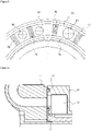
figure 2 est une représentation en perspective d'un réducteur selon l'invention. - La
figure 3 est une représentation d'un distributeur selon l'invention. - La
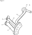
figure 4 est une représentation, en perspective, d'un module d'un distributeur selon l'invention. - La
figure 5 est une représentation d'une sortie d'une canalisation d'un distributeur selon un mode de réalisation de l'invention. - La
figure 6 est une représentation d'une sortie d'une canalisation d'un distributeur selon un mode de réalisation de l'invention. - La
figure 7 est une représentation d'une sortie d'une canalisation d'un distributeur selon un mode de réalisation de l'invention. - La
figure 8 est une représentation schématique d'une étape de montage d'un réducteur selon l'invention. - La
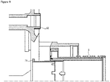
figure 9 est une représentation schématique d'une étape de montage d'un réducteur selon l'invention. - La
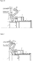
figure 10 est une représentation schématique d'une étape de montage d'un réducteur selon l'invention. - La
figure 11 est une représentation schématique d'une étape de montage d'un réducteur selon l'invention. - La
figure 1 décrit une turbomachine 1 qui comporte, de manière classique, une soufflante S, un compresseur basse pression 1a, un compresseur haute pression 1b, une chambre annulaire de combustion 1c, une turbine haute pression 1d, une turbine basse pression 1e et une tuyère d'échappement 1h. Le compresseur haute pression 1b et la turbine haute pression 1d sont reliés par un arbre haute pression 2 et forment avec lui un corps haute pression (HP). Le compresseur basse pression 1a et la turbine basse pression 1e sont reliés par un arbre basse pression 3 et forment avec lui un corps basse pression (BP). - La soufflante S est entraînée par un arbre de soufflante 4 qui est entrainé à l'arbre BP 3 au moyen d'un réducteur 6. Ce réducteur 6 est généralement de type planétaire ou épicycloïdal.
- En référence à la
figure 2 , le réducteur 6 comporte : - un solaire ayant un axe 61 de rotation,
- une couronne qui s'étend autour du solaire et qui est configurée pour être immobile en rotation autour dudit axe 61,
- des satellites qui sont engrenés avec le solaire et la couronne et qui sont maintenus par un porte-satellites 62 qui est configuré pour être mobile en rotation autour dudit axe 62,
- un distributeur 65 d'huile de lubrification,
- En outre, le distributeur 65 d'huile comprend une pluralité de modules 67 de distribution d'huile assemblés ensemble, chaque module 67 comprenant au moins une canalisation 68 de lubrification présentant une entrée destinée à recevoir de l'huile et une sortie 69 adaptée pour faire déboucher l'huile dans une ouverture 63 du porte-satellites 62, l'ouverture 63 étant destinée à la lubrification du réducteur.
- D'une manière particulièrement avantageuse, le distributeur selon l'invention permet un apport d'huile dans un champ tournant. La structure modulaire du distributeur permet que cet apport soit peu impactant sur la structure tout en étant facile à monter.
- D'une manière préférentielle, le porte-satellites 62 présente une pluralité d'ouvertures 63 équirépartie. Préférentiellement, le porte-satellites 62 comprend un nombre d'ouvertures défini par n fois le nombre de satellite.
- Selon une disposition préférentielle, le porte-satellites 62 est monobloc.
- Le distributeur 65 permet d'assurer une liaison fluidique entre un OTB 9 et le porte-satellites 62. En d'autres termes, le distributeur 65 permet un transfert d'huile de l'OTB 9 vers le porte-satellites 62.
- Comme indiqué précédemment, le distributeur 65 comprend une pluralité de modules 67 assemblés les uns aux autres. En d'autres termes, le distributeur 65 est un kit de plusieurs modules 67 distincts qui sont assemblés pour former ensemble un distributeur 65.
- Chaque module 67 comprend au moins une canalisation 68 permettant d'introduire de l'huile dans le porte-satellites 62. Comme cela est représenté, sur les figures, chaque module 67 peut présenter plusieurs canalisations 68. Tel que représenté sur les
figures 3 et4 , les différentes canalisations 68 d'un même module 67 peuvent présenter des orientations différentes. De même, les canalisations 68 d'un même module 67 peuvent présenter des diamètres différents. Typiquement, le diamètre d'une canalisation 68 peut être dicté par la quantité et la pression de l'huile qui doit y transiter. - Comme indiqué précédemment, chaque canalisation 68 présente une sortie 69 qui est destinée à être introduite dans une ouverture 63 correspondante du porte-satellite. La sortie 69 peut comprendre des moyens d'étanchéité, les moyens d'étancheité comprenant au moins un joint torique 72 permettant d'assurer l'étanchéité d'une liaison de la sortie 69 avec l'ouverture 63.
- Selon un autre mode de réalisation, représenté en
figure 5 et 6 , les moyens d'étanchéité peuvent comprendre une combinaison de deux joints toriques 72 et d'un labyrinthe radial 75. Les joints toriques 72 permettent de garantir une étanchéité entre la sortie 69 et l'extérieur. Les labyrinthes 75 permettent d'assurer une étanchéité entre les différentes canalisations 68. - Selon un autre mode de réalisation, représenté en
figure 7 , la sortie 69 peut présenter une combinaison de deux joints toriques 72 et d'un labyrinthe radial 75 ou une bobine 76 comprenant un double joint torique 77 et un frettage 78. Il est précisé que la bobine 76 peut être une portion de cylindre encastrée dans la sortie 69 et liée de manière étanche à la sortie 69 grâce au double joint torique 77. La bobine est frettée dans l'ouverture 63, le frettage permettant aussi de garantir l'étanchéité de la liaison Cette disposition permet de combiner l'étanchéité et la tenue mécanique. Le frettage est une disposition particulièrement intéressante car cette liaison nécessite peu de moyens mécaniques tout en étant suffisamment robuste. En effet, comme indiqué précédemment, le distributeur 65 exerce très peu d'effort sur le porte-satellites 62. Dans ce contexte, le frettage est donc une solution de liaison suffisante et particulièrement adaptée. - En sus, les différents modules 67 peuvent être assemblés les uns aux autres par des boulons.
- D'une manière préférentielle, le distributeur 65 est maintenu entre le porte-satellites 62 et un écrou 79.
- Cette solution permet de totalement différentier la partie structurelle de la partie circuit d'huile et ainsi de laisser libre court au choix des matériaux, procédé de fabrication et géométrie, sans apporter un encombrement axial supplémentaire. Typiquement, les modules du distributeur 65 peuvent être réalisés par fabrication additive.
- Selon un autre aspect, l'invention propose un procédé d'assemblage d'un réducteur 6 selon l'invention.
- Le procédé peut comprendre au moins les étapes suivantes :
- positionnement de l'écrou 79 sur l'axe 61 ;
- introduction des extrémités distales 69 dans les ouvertures correspondantes du porte-satellites 62 ;
- rotation de chaque module 67 pour les assembler les uns aux autres entre le porte-satellites 62 et l'écrou 79 ;
- serrage de l'écrou 79.
- Plus précisément, en référence à la
figure 8 , l'écrou 79 est tout d'abord vissé sur l'OTB 9. - Puis, comme cela est représenté sur la
figure 9 , l'ensemble écrou 79 et OTB 9 est engagé contre le porte-satellites 62. - Chaque module 67 est ensuite engagé dans le porte-satellites 62. Comme représenté sur la
figure 10 , chaque module est engagé incliné (c'est-à-dire selon une direction sécante des directions axiale et radiale). - Puis, en référence à la
figure 11 , chaque module est rabattu pour que la sortie 69 soit enclenchée dans une ouverture 63, et que la liaison fluidique entre l'OTB 9 et le porte-satellites 62 soit assurée. - Enfin, l'écrou 79 est serré pour garantir le maintien des modules 67.
- Les modules 67 peuvent aussi être boulonnés les uns aux autres.
- On comprend donc bien que la structure modulaire du distributeur 65 permet un assemblage simple, qui ne nécessite pas de démontage du porte-satellites 62.
Claims (10)
- Réducteur (6) mécanique de turbomachine, en particulier d'aéronef, ce réducteur (6) comportant :- un solaire s'étendant autour d'un axe (61) de rotation,- une couronne qui s'étend autour du solaire et qui est configurée pour être immobile en rotation autour dudit axe (61),- des satellites qui sont engrenés avec le solaire et la couronne et qui sont maintenus par un porte-satellites (62) qui est configuré pour être mobile en rotation autour dudit axe (61),- un distributeur (65) d'huile de lubrification,caractérisé en ce que le distributeur (65) d'huile comprend une pluralité de modules (67) de distribution d'huile distincts, lesdits modules étant assemblés à l'extérieur du porte-satellites des sorte à former ensemble un distributeur 65, chaque module (67) comprenant au moins une canalisation (68) de lubrification présentant une entrée destinée à recevoir de l'huile et une sortie (69) adaptée pour faire déboucher l'huile dans une ouverture (63) du porte-satellites (62), l'ouverture (63) étant destinée à la lubrification du réducteur.
- Réducteur (6) selon la revendication 1, dans lequel chaque module (67) comprend une pluralité de canalisations (68).
- Réducteur (6) selon a revendication 2, dans lequel plusieurs canalisations (68) d'un même module (67) présentent des diamètres différents.
- Réducteur (6) selon l'une des revendications 2 ou 3, dans lequel plusieurs canalisations (68) d'un même module (67) présentent au moins deux orientations différentes.
- Réducteur (6) selon l'une quelconque des revendications précédentes, dans lequel le porte-satellites (62) présente une pluralité d'ouvertures (63) équiréparties.
- Réducteur (6) selon la revendication 5 dans lequel le porte-satellites (62) comprend un nombre d'ouvertures (63) défini par n fois le nombre de satellite.
- Réducteur (6) selon l'une quelconque des revendication 1 à 6, dans lequel la sortie (69) de chaque canalisation (68) comprend des moyens d'étanchéité, les moyens d'étanchéité comprenant au moins un joint torique (72) permettant d'assurer l'étanchéité d'une liaison de la sortie (69) avec chaque ouverture (63) correspondante.
- Réducteur (6) selon la revendication 7, dans lequel les moyens d'étanchéité comprennent une combinaison de deux joints toriques (72) et d'un labyrinthe radial (75) ou une bobine (76) comprenant un double joint torique (77) et un frettage (78).
- Réducteur (6) selon l'une quelconque des revendications 1 à 8, dans lequel le distributeur (65) est maintenu entre le porte-satellites (62) et un écrou (79).
- Procédé d'assemblage d'un réducteur (6) selon la revendication 9, caractérisé en ce qu'il comprend au moins les étapes suivantes :- positionnement de l'écrou (79) sur l'axe (61) ;- introduction des sorties (69) dans les ouvertures (63) correspondantes du porte-satellites (62) ;- rotation de chaque module (67) pour les assembler les uns aux autres entre le porte-satellites (62) et l'écrou (79) ;- serrage de l'écrou (79).
Applications Claiming Priority (1)
| Application Number | Priority Date | Filing Date | Title |
|---|---|---|---|
| FR2101036A FR3119431A1 (fr) | 2021-02-03 | 2021-02-03 | Réducteur mécanique |
Publications (1)
| Publication Number | Publication Date |
|---|---|
| EP4040019A1 true EP4040019A1 (fr) | 2022-08-10 |
Family
ID=75746805
Family Applications (1)
| Application Number | Title | Priority Date | Filing Date |
|---|---|---|---|
| EP22154887.8A Pending EP4040019A1 (fr) | 2021-02-03 | 2022-02-03 | Réducteur mécanique |
Country Status (4)
| Country | Link |
|---|---|
| US (1) | US11808213B2 (fr) |
| EP (1) | EP4040019A1 (fr) |
| CN (1) | CN114922960B (fr) |
| FR (1) | FR3119431A1 (fr) |
Families Citing this family (2)
| Publication number | Priority date | Publication date | Assignee | Title |
|---|---|---|---|---|
| IT202200017376A1 (it) * | 2022-08-17 | 2024-02-17 | Ge Avio Srl | Collettore d'olio flottante per sistemi ad ingranaggi epicicloidali |
| US12152667B1 (en) * | 2024-03-08 | 2024-11-26 | Schaeffler Technologies AG & Co. KG | Gearbox cover with planetary carrier |
Citations (5)
| Publication number | Priority date | Publication date | Assignee | Title |
|---|---|---|---|---|
| US20150139802A1 (en) * | 2013-11-20 | 2015-05-21 | Snecma | Device for supplying oil under pressure to a linear actuator of a turbine engine |
| US20200096089A1 (en) * | 2016-03-29 | 2020-03-26 | Mitsubishi Electric Corporation | Planetary gear device and vehicle wheel drive device |
| US20200191258A1 (en) * | 2018-12-13 | 2020-06-18 | Safran Transmission Systems | Planet-carrier for a reduction gear of the planetary type |
| US20200208577A1 (en) * | 2017-07-05 | 2020-07-02 | Safran Transmission Systems | Ring gear for an epicylic or planetary reduction gear of a turbomachine |
| EP3696449A1 (fr) * | 2019-02-14 | 2020-08-19 | Safran Transmission Systems | Lubrification d'un porte-satellites pour un reducteur mecanique de turbomachine, en particulier d'aeronef |
Family Cites Families (5)
| Publication number | Priority date | Publication date | Assignee | Title |
|---|---|---|---|---|
| ITUA20162735A1 (it) * | 2016-04-20 | 2017-10-20 | Ge Avio Srl | Unita' di trasferimento d'olio per trasferire olio tra una parte statica ed una parte rotante |
| FR3065046B1 (fr) * | 2017-04-06 | 2019-04-19 | Safran Transmission Systems | Rouet pour un porte-satellites de reducteur de vitesse a train epicycloidal de turbomachine |
| FR3069300B1 (fr) * | 2017-07-20 | 2019-07-26 | Safran Transmission Systems | Ensemble comportant un rouet de lubrification et des gicleurs de lubrifiant, pour un reducteur de vitesse a train epicycloidal de turbomachine |
| FR3092888B1 (fr) * | 2019-02-14 | 2021-01-22 | Safran Trans Systems | Lubrification d’un porte-satellites pour un reducteur mecanique de turbomachine, en particulier d’aeronef |
| FR3093550B1 (fr) * | 2019-03-07 | 2021-02-19 | Safran Aircraft Engines | Reducteur mecanique de turbomachine d’aeronef |
-
2021
- 2021-02-03 FR FR2101036A patent/FR3119431A1/fr active Pending
-
2022
- 2022-01-24 US US17/582,546 patent/US11808213B2/en active Active
- 2022-01-29 CN CN202210110041.0A patent/CN114922960B/zh active Active
- 2022-02-03 EP EP22154887.8A patent/EP4040019A1/fr active Pending
Patent Citations (6)
| Publication number | Priority date | Publication date | Assignee | Title |
|---|---|---|---|---|
| US20150139802A1 (en) * | 2013-11-20 | 2015-05-21 | Snecma | Device for supplying oil under pressure to a linear actuator of a turbine engine |
| US20200096089A1 (en) * | 2016-03-29 | 2020-03-26 | Mitsubishi Electric Corporation | Planetary gear device and vehicle wheel drive device |
| US20200208577A1 (en) * | 2017-07-05 | 2020-07-02 | Safran Transmission Systems | Ring gear for an epicylic or planetary reduction gear of a turbomachine |
| US20200191258A1 (en) * | 2018-12-13 | 2020-06-18 | Safran Transmission Systems | Planet-carrier for a reduction gear of the planetary type |
| EP3696449A1 (fr) * | 2019-02-14 | 2020-08-19 | Safran Transmission Systems | Lubrification d'un porte-satellites pour un reducteur mecanique de turbomachine, en particulier d'aeronef |
| US20200300173A1 (en) * | 2019-02-14 | 2020-09-24 | Safran Transmission Systems | Lubrication of a planet-carrier for a mechanical reduction gear of a turbine engine, in particular of an aircraft |
Also Published As
| Publication number | Publication date |
|---|---|
| FR3119431A1 (fr) | 2022-08-05 |
| CN114922960A (zh) | 2022-08-19 |
| CN114922960B (zh) | 2025-10-24 |
| US11808213B2 (en) | 2023-11-07 |
| US20220243662A1 (en) | 2022-08-04 |
Similar Documents
| Publication | Publication Date | Title |
|---|---|---|
| EP3726031B1 (fr) | Reducteur mecanique de turbomachine d aeronef | |
| EP3922886B1 (fr) | Reducteur mecanique de turbomachine d'aeronef | |
| EP3892895B1 (fr) | Reducteur mecanique de turbomachine d'aeronef | |
| EP4034797B1 (fr) | Restricteur d'huile pour la lubrification de secours d'un élément de turbomachine d'aéronef | |
| EP3705705B1 (fr) | Réducteur mécanique de turbomachine d'aéronef | |
| FR3111390A1 (fr) | Reducteur mecanique de turbomachine d’aeronef | |
| EP4108900B1 (fr) | Porte-satellites pour un reducteur de vitesse de turbomachine d'aeronef | |
| EP4040019A1 (fr) | Réducteur mécanique | |
| EP4336070B1 (fr) | Ensemble d'entrainement pour un reducteur mecanique de turbomachine d'aeronef | |
| EP4108899A1 (fr) | Porte-satellites pour un reducteur de vitesse de turbomachine d'aeronef | |
| EP4382769B1 (fr) | Couronne pour un reducteur mecanique d'aeronef | |
| EP4336059B1 (fr) | Palier lisse pour un réducteur mécanique de turbomachine d'aéronef | |
| FR3098548A1 (fr) | Reducteur mecanique pour une turbomachine d’aeronef | |
| EP3896311B1 (fr) | Dispositif de transfert d'huile | |
| EP4033086A1 (fr) | Turbomachine d'aeronef a triple flux equipe d'un module de transmission de puissance | |
| EP4023909A1 (fr) | Porte-satellites pour un reducteur mecanique de turbomachine d aeronef | |
| FR3128753A1 (fr) | Reducteur mecanique de vitesse pour une turbomachine d’aeronef | |
| FR3114367A1 (fr) | Réducteur amélioré pour le maintien de couronne. | |
| EP4123190B1 (fr) | Réducteur mécanique pour turbomachine à gaz d'axe longitudinal | |
| EP4471295B1 (fr) | Solaire pour un réducteur mécanique de turbomachine d' aéronef | |
| WO2026003459A1 (fr) | Reducteur mecanique pour une turbomachine d'aeronef | |
| FR3145588A1 (fr) | Turbomachine comprenant un reducteur de vitesse ayant des brides de fixation accouplees par un accouplement a dentures. | |
| WO2026003458A1 (fr) | Reducteur mecanique pour une turbomachine d'aeronef | |
| FR3106384A1 (fr) | Porte-satellites pour un reducteur mecanique de turbomachine d’aeronef | |
| FR3159197A1 (fr) | Reducteur pour un aeronef |
Legal Events
| Date | Code | Title | Description |
|---|---|---|---|
| PUAI | Public reference made under article 153(3) epc to a published international application that has entered the european phase |
Free format text: ORIGINAL CODE: 0009012 |
|
| STAA | Information on the status of an ep patent application or granted ep patent |
Free format text: STATUS: REQUEST FOR EXAMINATION WAS MADE |
|
| 17P | Request for examination filed |
Effective date: 20220203 |
|
| AK | Designated contracting states |
Kind code of ref document: A1 Designated state(s): AL AT BE BG CH CY CZ DE DK EE ES FI FR GB GR HR HU IE IS IT LI LT LU LV MC MK MT NL NO PL PT RO RS SE SI SK SM TR |
|
| STAA | Information on the status of an ep patent application or granted ep patent |
Free format text: STATUS: EXAMINATION IS IN PROGRESS |
|
| 17Q | First examination report despatched |
Effective date: 20240612 |
|
| 17Q | First examination report despatched |
Effective date: 20240626 |