EP4040015A1 - Compact epicyclic gearing - Google Patents
Compact epicyclic gearing Download PDFInfo
- Publication number
- EP4040015A1 EP4040015A1 EP21156102.2A EP21156102A EP4040015A1 EP 4040015 A1 EP4040015 A1 EP 4040015A1 EP 21156102 A EP21156102 A EP 21156102A EP 4040015 A1 EP4040015 A1 EP 4040015A1
- Authority
- EP
- European Patent Office
- Prior art keywords
- gearing
- shaft
- planet
- gear
- planet carrier
- Prior art date
- Legal status (The legal status is an assumption and is not a legal conclusion. Google has not performed a legal analysis and makes no representation as to the accuracy of the status listed.)
- Granted
Links
Images


Classifications
-
- F—MECHANICAL ENGINEERING; LIGHTING; HEATING; WEAPONS; BLASTING
- F16—ENGINEERING ELEMENTS AND UNITS; GENERAL MEASURES FOR PRODUCING AND MAINTAINING EFFECTIVE FUNCTIONING OF MACHINES OR INSTALLATIONS; THERMAL INSULATION IN GENERAL
- F16H—GEARING
- F16H37/00—Combinations of mechanical gearings, not provided for in groups F16H1/00 - F16H35/00
- F16H37/02—Combinations of mechanical gearings, not provided for in groups F16H1/00 - F16H35/00 comprising essentially only toothed or friction gearings
-
- B—PERFORMING OPERATIONS; TRANSPORTING
- B60—VEHICLES IN GENERAL
- B60K—ARRANGEMENT OR MOUNTING OF PROPULSION UNITS OR OF TRANSMISSIONS IN VEHICLES; ARRANGEMENT OR MOUNTING OF PLURAL DIVERSE PRIME-MOVERS IN VEHICLES; AUXILIARY DRIVES FOR VEHICLES; INSTRUMENTATION OR DASHBOARDS FOR VEHICLES; ARRANGEMENTS IN CONNECTION WITH COOLING, AIR INTAKE, GAS EXHAUST OR FUEL SUPPLY OF PROPULSION UNITS IN VEHICLES
- B60K17/00—Arrangement or mounting of transmissions in vehicles
- B60K17/04—Arrangement or mounting of transmissions in vehicles characterised by arrangement, location or kind of gearing
- B60K17/043—Transmission unit disposed in on near the vehicle wheel, or between the differential gear unit and the wheel
- B60K17/046—Transmission unit disposed in on near the vehicle wheel, or between the differential gear unit and the wheel with planetary gearing having orbital motion
-
- B—PERFORMING OPERATIONS; TRANSPORTING
- B60—VEHICLES IN GENERAL
- B60Y—INDEXING SCHEME RELATING TO ASPECTS CROSS-CUTTING VEHICLE TECHNOLOGY
- B60Y2200/00—Type of vehicle
- B60Y2200/20—Off-Road Vehicles
- B60Y2200/25—Track vehicles
-
- F—MECHANICAL ENGINEERING; LIGHTING; HEATING; WEAPONS; BLASTING
- F16—ENGINEERING ELEMENTS AND UNITS; GENERAL MEASURES FOR PRODUCING AND MAINTAINING EFFECTIVE FUNCTIONING OF MACHINES OR INSTALLATIONS; THERMAL INSULATION IN GENERAL
- F16H—GEARING
- F16H1/00—Toothed gearings for conveying rotary motion
- F16H1/28—Toothed gearings for conveying rotary motion with gears having orbital motion
- F16H1/46—Systems consisting of a plurality of gear trains each with orbital gears, i.e. systems having three or more central gears
-
- F—MECHANICAL ENGINEERING; LIGHTING; HEATING; WEAPONS; BLASTING
- F16—ENGINEERING ELEMENTS AND UNITS; GENERAL MEASURES FOR PRODUCING AND MAINTAINING EFFECTIVE FUNCTIONING OF MACHINES OR INSTALLATIONS; THERMAL INSULATION IN GENERAL
- F16H—GEARING
- F16H57/00—General details of gearing
- F16H57/02—Gearboxes; Mounting gearing therein
- F16H57/029—Gearboxes; Mounting gearing therein characterised by means for sealing the gearboxes, e.g. to improve airtightness
-
- F—MECHANICAL ENGINEERING; LIGHTING; HEATING; WEAPONS; BLASTING
- F16—ENGINEERING ELEMENTS AND UNITS; GENERAL MEASURES FOR PRODUCING AND MAINTAINING EFFECTIVE FUNCTIONING OF MACHINES OR INSTALLATIONS; THERMAL INSULATION IN GENERAL
- F16H—GEARING
- F16H57/00—General details of gearing
- F16H57/04—Features relating to lubrication or cooling or heating
- F16H57/0434—Features relating to lubrication or cooling or heating relating to lubrication supply, e.g. pumps; Pressure control
- F16H57/0445—Features relating to lubrication or cooling or heating relating to lubrication supply, e.g. pumps; Pressure control for supply of different gearbox casings or sections
-
- F—MECHANICAL ENGINEERING; LIGHTING; HEATING; WEAPONS; BLASTING
- F16—ENGINEERING ELEMENTS AND UNITS; GENERAL MEASURES FOR PRODUCING AND MAINTAINING EFFECTIVE FUNCTIONING OF MACHINES OR INSTALLATIONS; THERMAL INSULATION IN GENERAL
- F16H—GEARING
- F16H57/00—General details of gearing
- F16H57/04—Features relating to lubrication or cooling or heating
- F16H57/048—Type of gearings to be lubricated, cooled or heated
- F16H57/0482—Gearings with gears having orbital motion
- F16H57/0486—Gearings with gears having orbital motion with fixed gear ratio
-
- F—MECHANICAL ENGINEERING; LIGHTING; HEATING; WEAPONS; BLASTING
- F16—ENGINEERING ELEMENTS AND UNITS; GENERAL MEASURES FOR PRODUCING AND MAINTAINING EFFECTIVE FUNCTIONING OF MACHINES OR INSTALLATIONS; THERMAL INSULATION IN GENERAL
- F16H—GEARING
- F16H7/00—Gearings for conveying rotary motion by endless flexible members
- F16H7/06—Gearings for conveying rotary motion by endless flexible members with chains
Definitions
- the present invention refers to the technical sector of motion reduction mechanisms interposed between driving shaft and shaft at reduced speed, in particular it refers to a compact epicyclic gearing.
- the known epicyclic reduction gearings have a sun gear, a planet carrier and an internal toothing outer gear. These elements transmit motion by means of a plurality of planet gears which are rotatably fixed to the planet carrier and which rotate with a fixed distance between centres.
- the motion input is applied to the sun gear shaft and it is transmitted, by means of the plurality of planet gear, to the planet carrier provided with the output shaft.
- Document US5074829 discloses an epicyclic gear with an input shaft kinematically connected to two planet gears supported by a planet carrier wherein each planet gear is made on a relative shaft supporting a relative pulley engaged by a first annular belt or chain which is engaged with a pinion keyed on the input shaft.
- the rotation of the input shaft is transmitted, through the belt or chain, to each pulley which set in rotation the relative shaft supporting the relative planetary gear driving into rotation the planet carrier having the axis coaxial with the input shaft axis.
- the torque support for the epicyclic gear is realized with a second chain on a sprocket of the planet gear, which is meshing with a sprocket that is fixed to the casing.
- the document CA 1154982 discloses a speed reducer in which a reaction sun is held stationary relative to a frame and an output sun is coaxial with the reaction sun.
- An idler carrier assembly rotatable relative to the frame about the common axis of the two suns, carries a planet shaft supporting a reaction planet and an output planet for conjoint rotation and in radial alignment, respectively, with the reaction sun and the output sun.
- Rotation of the idler carrier assembly effects orbiting of the planet shaft and its planets about the common axis of the suns.
- Endless loop force-transmitting elements connect corresponding suns and planets.
- Rotary input power is applied to the planet shaft effecting conjoint rotation of planets and orbiting of the planets about the suns' axis.
- the epicyclic motion of the output planet effects rotation of the output sun.
- an articulated gearing comprising drive outer tooth sprocket and driven sprocket and two-row roller chain to transfer first power flow.
- Two gears fitted on one axle with equal number of teeth engage with said drive and driven sprockets to make the second power flow.
- Said first power flow comprises two extra rollers fitted on parallel axles and bus supporting aforesaid roller chain.
- Driven sprocket has inner teeth for engagement with one of gears and roller chain.
- Drive and driven sprockets are fitted at equal axle base equal to or approximating to zero and feature different number of teeth.
- Said bus is arranged with clearance to driven sprocket inner surface for passage of roller chain. The transmission of torque from drive shaft to driven shaft at axle base is equal to or approximating to zero.
- European Patent Application EP3293415 discloses a solution referring to a common kinematic relationships of planetary gear trains using a sun gear, a planet gear and an outer gear which is internal to the case.
- it provides an internal ring gear, a driving assembly having the internal ring gear, and an application device employing the driving assembly.
- the internal ring gear includes at least two ring gears integrally arranged in parallel at an inner surface of a single housing.
- the main drawback of known epicyclic reduction gears lies in the fact that the gears are multiple with several gearings in motion and therefore noisy as well as bulky when the diameters, for example of the satellites, are wide.
- the known epicyclic gears also have the drawback of having limited contact between the teeth of the mutually meshed gearings and therefore without allowing a considerable size reduction.
- the main object of the present invention is to propose a compact epicyclic gearing by virtue of the considerable increase of the mutually meshed portions so as to reduce the axial overall dimensions of the meshed gearings.
- Another object is to propose a gearing with multiple gearings having increased stability and reduced noise.
- a further object is to propose a gearing having a high reduction ratio.
- numeral 50 indicates an epicyclic gearing having a first stage 14 essentially comprising an input shaft 1, a pinion 2, three first sun gears 11, a belt or chain 3, three pulleys 4, three first planet gears 13, a first planet carrier 9, a first outer gear 15 and a case 22.
- the pinion 2 is keyed on the input shaft 1 on whose teeth the belt or chain 3 engages, constituting a flexible annular gearing 16 which transmits the motion of the pinion 2 to the three pulleys 4 on which the annular gearing 16 is wound.
- the belt 3 is kept taut by a tightener 23.
- Each pulley 4 is keyed by conical sleeves 5 to the end of a respective shaft 6 which is rotatably supported by the first planet carrier 9 by means of a first bearing 7 and a second bearing 8.
- each shaft 6 there are toothings which constitute the respective first sun gear 11.
- the three pulleys 4 are angularly spaced at 120° with the respective axes on the same circumference.
- the three first sun gears 11 are angularly spaced at 120° and are coaxial with the corresponding pulleys 4.
- the first planet carrier 9 supports the three first planet gears 13 by means of a respective pin 35 with the interposition of a bearing 36 and is held in place by means of a shoulder 10 cooperating with a stiffening 12.
- Each first sun gear 11 meshes simultaneously with two adjacent planet gears 13.
- Each first planet gear 13 also engages with the first fixed outer gear 15 obtained on the inner wall of the case 22.
- the operation of the preferred embodiment of the epicyclic gearing 50 provides that the rotary motion of the input shaft 1 is transferred to each pulley 4 through the synchronous transmission of belt 3, with motion reversal and a first speed reduction.
- each pulley 4 rotates the shaft 6 of the respective first sun gear 11.
- the shaft 6 axis is parallel to the axis of the input shaft 1 and is assigned to travel along a circumference, dragging in rotation, by means of the respective first planet gear 13, the first planet carrier 9 whose rotation axis is coaxial to the axis of the input shaft 1 and from which it is possible to take a reduced rotary motion with respect to the motion of the input shaft 1.
- a second embodiment of the epicyclic gearing 50 provides a second stage 18 placed in cascade to the first stage 14 in order to increase the reduction ratio of the rotary motion applied to the input shaft 1.
- Each of these four second planet gears 37 is rotatably supported by a corresponding rod 48 constrained to a second planet carrier 39.
- the second planet carrier 39 is meshed with a second outer gear 38 made on the internal portion of the case 22.
- the second planet carrier 39 is coupled with an output shaft 20 coaxial with the input shaft 1 and carrying a reduced tail shaft 24 which rotatably supports the second sun gear 17 through two bushes or slides 25.
- the shaft 20 is axially controlled and tightly supported at the output by a single double-gears taper roller bearing 21 and by the same output flange 34.
- the case 22 is provided with an input flange 26 and an output flange 34 so creating a chamber having a first and a second compartment.
- the first compartment is comprised between the input flange 26 and the first planet carrier 9 and encloses the annular gearing 16 so as to keep it isolated by means of a lip seal 31 interposed between the inner portion 30 of the case 22 and the shoulder 10 for supporting the first planet carrier 9.
- the second compartment is comprised between the first compartment, the case 22, the output shaft 20 and the output flange 34.
- the second compartment contains the first stage 14 and the second stage 18 of the epicyclic gearing 50 so keeping them into a lubricant bath by virtue of the sealing of the lip seal 31 and of a front seal 33, interposed between the output shaft 20 and the output flange 34, and by an o-ring 32, interposed between the output flange 34 and the inner portion 30 of the case 22.
- the plurality of meshing points between the first sun gears 11 and the respective first planet gears 13 does not have hyperstatic problems due to the right relationship between the tensioning of the belt 3 by the tightener 23 and the appropriate freedom degree of the bearings, first 7 and second 8, in the respective housing.
- the sun gear In a stage of a known epicyclic gearing, the sun gear is positioned at the gearing centre and is engaged in only three points with the respective planets arranged at 120° around it.
- the first three sun gears 11 are radially decentralized and are each interposed between two respective first planet gears 13 with a doubling of the grip points with respect to the corresponding stage of the known gearing.
- Each of the gripping points consists of two teeth of the first sun gear 11 which are always conjugated with two teeth of the respective first planet gear 13 due to the conduct ratio always higher than 1, i.e. ⁇ >1 according to UNI 8862 standard.
- the axes of the three first sun gears 11 and the axes of the three pulleys 4 trace the same circumference and therefore travel at the same angular speed ⁇ corresponding to a peripheral speed of less than one meter per second.
- the tangential force, in the known epicyclic gearings with three planet gears and one sun gear, taken in a single point is Ft/3, while in the first stage 14 the tangential force is Ft/6 as there are six grip points between the first sun gears 11 and the first planet gears 13.
- the overall stabilization of the epicyclic gearing 50, in the radial and axial direction, is guaranteed by the reduced tail shaft 24 of the output shaft 20 and by the perfect alignment with the input shaft 1.
- the controlled flotation of the entire epicyclic gearing 50 is controlled by the bushes 25 mounted inside the second sun gear 17 and contained downstream in an anti-sliding function with respect to the input flange 26, by the supporting balls 27 mounted on the fixing pins 28 of the closed curved rolling bearings 29.
- rolling bearings 29 are placed at an equal radial distance from the axis of the input shaft 1 and are mounted on the shoulder 10 of the first planet carrier 9. During the operation of the epicyclic gearing 50, the rolling bearings 29 also move with rototranslatory motion at already reduced speed along the internal circumference of the case 22 thus contributing to the radial equilibrium of the epicyclic gearing 50 in the operating phase.
- the two embodiments of the gearing 50 just described provide for the use of the gearing as a reducer in which the driving force (rotary motion) is applied to the input shaft 1 and the reduced motion is available at the output shaft 20.
- a variant of use of the two embodiments of the epicyclic gearing 50 provides that it is used as a multiplier in which the input rotary motion is applied to the output shaft 20 and the multiplied motion is taken from the input shaft 1.
- the overall dimensions of the epicyclic gearing 50, object of the present invention have an axial overall dimensions of 370 mm between an inner face 51 of the input flange 26 and an outer face 52 of the output flange 34. Therefore, the axial overall dimensions between the gearing 50 and the known one is reduced by about 30%.
- output flange 34 can be square or round shaped based on the type of installation required.
- Figures 4 and 5 illustrate a third embodiment of the compact epicyclic gearing 50 which is single-stage and comprises the same annular gearing 16 of the first and second embodiments.
- the first planet carrier 9 is essentially connected by means of three stiffenings 12 to the shoulder 10 which has on its peripheral edge a tractor wheel 60 on which, for example, a track 61 engages.
- the motion output from the gearing 50 is from the shoulder 10 to which the tractor wheel 60 is constrained, for example of a not showed but known tracked vehicle.
- the main advantage of the present invention is to provide a compact epicyclic gearing obtained thanks to the considerable increase in the number and surfaces of the mutually meshed portions so as to reduce the axial development of the meshed gearings.
- a first axial compression is obtained as a result of the particular configuration of the first stage of the epicyclic gearing with the multiple sun gears off-cantered with respect to the axis of the input shaft and which are moved by a flexible annular gearing acting within the axial overall dimensions of the input shaft itself.
- Another advantage consists in providing a gearing with multiple gearings having increased stability and reduced noise.
- a further advantage is that of providing a gearing having a high reduction ratio.
Landscapes
- Engineering & Computer Science (AREA)
- Mechanical Engineering (AREA)
- Chemical & Material Sciences (AREA)
- Combustion & Propulsion (AREA)
- Transportation (AREA)
- General Engineering & Computer Science (AREA)
- Retarders (AREA)
Abstract
Description
- The present invention refers to the technical sector of motion reduction mechanisms interposed between driving shaft and shaft at reduced speed, in particular it refers to a compact epicyclic gearing.
- The known epicyclic reduction gearings have a sun gear, a planet carrier and an internal toothing outer gear. These elements transmit motion by means of a plurality of planet gears which are rotatably fixed to the planet carrier and which rotate with a fixed distance between centres.
- Generally, to obtain a reduction ratio of the number of revolutions between the input shaft and the output shaft, the motion input is applied to the sun gear shaft and it is transmitted, by means of the plurality of planet gear, to the planet carrier provided with the output shaft.
- Vice versa, when the epicyclic gearing is used to multiply the revolution numbers, the input motion is applied to the planet carrier shaft and the output motion is taken from the sun gear shaft.
- Document
US5074829 discloses an epicyclic gear with an input shaft kinematically connected to two planet gears supported by a planet carrier wherein each planet gear is made on a relative shaft supporting a relative pulley engaged by a first annular belt or chain which is engaged with a pinion keyed on the input shaft. The rotation of the input shaft is transmitted, through the belt or chain, to each pulley which set in rotation the relative shaft supporting the relative planetary gear driving into rotation the planet carrier having the axis coaxial with the input shaft axis. The torque support for the epicyclic gear is realized with a second chain on a sprocket of the planet gear, which is meshing with a sprocket that is fixed to the casing. - The document
CA 1154982 discloses a speed reducer in which a reaction sun is held stationary relative to a frame and an output sun is coaxial with the reaction sun. An idler carrier assembly, rotatable relative to the frame about the common axis of the two suns, carries a planet shaft supporting a reaction planet and an output planet for conjoint rotation and in radial alignment, respectively, with the reaction sun and the output sun. Rotation of the idler carrier assembly effects orbiting of the planet shaft and its planets about the common axis of the suns. Endless loop force-transmitting elements connect corresponding suns and planets. Rotary input power is applied to the planet shaft effecting conjoint rotation of planets and orbiting of the planets about the suns' axis. The epicyclic motion of the output planet effects rotation of the output sun. - In the document
RU 2520185 - European Patent Application
EP3293415 discloses a solution referring to a common kinematic relationships of planetary gear trains using a sun gear, a planet gear and an outer gear which is internal to the case. In particular it provides an internal ring gear, a driving assembly having the internal ring gear, and an application device employing the driving assembly. The internal ring gear includes at least two ring gears integrally arranged in parallel at an inner surface of a single housing. - The main drawback of known epicyclic reduction gears lies in the fact that the gears are multiple with several gearings in motion and therefore noisy as well as bulky when the diameters, for example of the satellites, are wide.
- The known epicyclic gears also have the drawback of having limited contact between the teeth of the mutually meshed gearings and therefore without allowing a considerable size reduction.
- The main object of the present invention is to propose a compact epicyclic gearing by virtue of the considerable increase of the mutually meshed portions so as to reduce the axial overall dimensions of the meshed gearings.
- Another object is to propose a gearing with multiple gearings having increased stability and reduced noise.
- A further object is to propose a gearing having a high reduction ratio.
- The features of the invention are highlighted hereinafter, with specific reference to the accompanying drawings, in which:
-
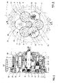
Figure 1 illustrates an axial sectional view of a first and a second embodiment of the gearing object of the invention in which parts have been removed to better highlight others; -
Figure 2 illustrates a section view according to plane II-II of the gearing ofFigure 1 ; -
Figure 3 illustrates a sectional view according to plane III-III of the gearing ofFigure 1 ;
Figure 4 illustrates a frontal view of the gearing ofFigure 1 in which some parts have been removed to better highlight others; -
Figure 5 illustrates a sectional view according to plane V-V ofFigure 4 . - With reference to
Figures 1-3 ,numeral 50 indicates an epicyclic gearing having afirst stage 14 essentially comprising aninput shaft 1, apinion 2, threefirst sun gears 11, a belt orchain 3, threepulleys 4, threefirst planet gears 13, afirst planet carrier 9, a firstouter gear 15 and acase 22. - The
pinion 2 is keyed on theinput shaft 1 on whose teeth the belt orchain 3 engages, constituting a flexibleannular gearing 16 which transmits the motion of thepinion 2 to the threepulleys 4 on which theannular gearing 16 is wound. Thebelt 3 is kept taut by atightener 23. - Each
pulley 4 is keyed byconical sleeves 5 to the end of arespective shaft 6 which is rotatably supported by thefirst planet carrier 9 by means of a first bearing 7 and a second bearing 8. - At the free end of each
shaft 6 there are toothings which constitute the respectivefirst sun gear 11. - The three
pulleys 4 are angularly spaced at 120° with the respective axes on the same circumference. Likewise, the threefirst sun gears 11 are angularly spaced at 120° and are coaxial with thecorresponding pulleys 4. - The
first planet carrier 9 supports the threefirst planet gears 13 by means of arespective pin 35 with the interposition of abearing 36 and is held in place by means of ashoulder 10 cooperating with a stiffening 12. - Each
first sun gear 11 meshes simultaneously with twoadjacent planet gears 13. - Each
first planet gear 13 also engages with the first fixedouter gear 15 obtained on the inner wall of thecase 22. - The operation of the preferred embodiment of the
epicyclic gearing 50 provides that the rotary motion of theinput shaft 1 is transferred to eachpulley 4 through the synchronous transmission ofbelt 3, with motion reversal and a first speed reduction. - Then each
pulley 4 rotates theshaft 6 of the respectivefirst sun gear 11. - The
shaft 6 axis is parallel to the axis of theinput shaft 1 and is assigned to travel along a circumference, dragging in rotation, by means of the respectivefirst planet gear 13, thefirst planet carrier 9 whose rotation axis is coaxial to the axis of theinput shaft 1 and from which it is possible to take a reduced rotary motion with respect to the motion of theinput shaft 1. - It should be noted that the rotation of the
annular gearing 16 constitutes an important flywheel with a positive impact on the efficiency of theepicyclic gearing 50. - A second embodiment of the
epicyclic gearing 50 provides asecond stage 18 placed in cascade to thefirst stage 14 in order to increase the reduction ratio of the rotary motion applied to theinput shaft 1. - A
second sun gear 17, coaxial to theinput shaft 1 and meshing with foursecond planet gears 37, is coupled to thefirst planet carrier 9 by means of aspline 49. Each of these foursecond planet gears 37 is rotatably supported by acorresponding rod 48 constrained to asecond planet carrier 39. - The
second planet carrier 39 is meshed with a secondouter gear 38 made on the internal portion of thecase 22. - The
second planet carrier 39 is coupled with anoutput shaft 20 coaxial with theinput shaft 1 and carrying a reducedtail shaft 24 which rotatably supports thesecond sun gear 17 through two bushes orslides 25. - The
shaft 20 is axially controlled and tightly supported at the output by a single double-gears taper roller bearing 21 and by thesame output flange 34. - The
case 22 is provided with aninput flange 26 and anoutput flange 34 so creating a chamber having a first and a second compartment. - The first compartment is comprised between the
input flange 26 and thefirst planet carrier 9 and encloses theannular gearing 16 so as to keep it isolated by means of alip seal 31 interposed between theinner portion 30 of thecase 22 and theshoulder 10 for supporting thefirst planet carrier 9. - The second compartment is comprised between the first compartment, the
case 22, theoutput shaft 20 and theoutput flange 34. The second compartment contains thefirst stage 14 and thesecond stage 18 of theepicyclic gearing 50 so keeping them into a lubricant bath by virtue of the sealing of thelip seal 31 and of afront seal 33, interposed between theoutput shaft 20 and theoutput flange 34, and by an o-ring 32, interposed between theoutput flange 34 and theinner portion 30 of thecase 22. - The plurality of meshing points between the
first sun gears 11 and the respectivefirst planet gears 13 does not have hyperstatic problems due to the right relationship between the tensioning of thebelt 3 by thetightener 23 and the appropriate freedom degree of the bearings, first 7 and second 8, in the respective housing. - In a stage of a known epicyclic gearing, the sun gear is positioned at the gearing centre and is engaged in only three points with the respective planets arranged at 120° around it.
- In the
first stage 14 of theepicyclic gearing 50, the first three sun gears 11 are radially decentralized and are each interposed between two respective first planet gears 13 with a doubling of the grip points with respect to the corresponding stage of the known gearing. - Each of the gripping points consists of two teeth of the
first sun gear 11 which are always conjugated with two teeth of the respectivefirst planet gear 13 due to the conduct ratio always higher than 1, i.e. εα >1 according to UNI 8862 standard. - This arrangement is made possible by the flexible
annular gearing 16 which, starting from thepinion 2 keyed onto theinput shaft 1, distributes the drive torque to the threepulleys 4 and, with a first speed reduction, to the integral first sun gears 11. These latter engage externally with the respective first planet gears 13 and with the contribution of the first fixedouter gear 15 put thefirst planet carrier 9 into rotary motion, reinforced by the flywheel effect impressed by thepulleys 4, with the impact of the reduction process onto thefirst planet carrier 9 and transmission to thesecond stage 18. - The axes of the three first sun gears 11 and the axes of the three
pulleys 4 trace the same circumference and therefore travel at the same angular speed ω corresponding to a peripheral speed of less than one meter per second. - This particular conformation of the
first stage 14, compared to the known three-stage epicyclic gearing, reduces the acoustic impact by over 50% and improves the efficiency by about 2% compared to the efficiency of 91% of the known epicyclic gearings. - In known epicyclic gearings, the dynamic stress is calculated as σFLim 1000
Nmm 2 ∗ 0,7 = 700 Nmm2 with reference tocase hardening steel 17 NI CR MO 4-6 - DIN 17210, while the dynamic bending stress of theepicyclic gearing 50 is 10% reduced since σFLim 1000Nmm 2 ∗ 0,8 = 800 Nmm2 due to the effect of the grip in two points at 120° on eachfirst planet gear 13, considered idler gear, of two first sun gears 11. - The tangential force, in the known epicyclic gearings with three planet gears and one sun gear, taken in a single point is Ft/3, while in the
first stage 14 the tangential force is Ft/6 as there are six grip points between the first sun gears 11 and the first planet gears 13. - Known single-sun epicyclic gearings reach a reduction ratio of at most 1:6, while in the
first stage 14 the reduction ratio is 1:12 or 1:12,5 by virtue of the 12 teeth engaged between the first sun gears 11 and the first planet gears 13 maintaining the character of torque reducer. - The overall stabilization of the
epicyclic gearing 50, in the radial and axial direction, is guaranteed by the reducedtail shaft 24 of theoutput shaft 20 and by the perfect alignment with theinput shaft 1. - The controlled flotation of the entire
epicyclic gearing 50 is controlled by thebushes 25 mounted inside thesecond sun gear 17 and contained downstream in an anti-sliding function with respect to theinput flange 26, by the supportingballs 27 mounted on the fixing pins 28 of the closed curved rollingbearings 29. - These rolling
bearings 29 are placed at an equal radial distance from the axis of theinput shaft 1 and are mounted on theshoulder 10 of thefirst planet carrier 9. During the operation of theepicyclic gearing 50, the rollingbearings 29 also move with rototranslatory motion at already reduced speed along the internal circumference of thecase 22 thus contributing to the radial equilibrium of theepicyclic gearing 50 in the operating phase. - The two embodiments of the
gearing 50 just described provide for the use of the gearing as a reducer in which the driving force (rotary motion) is applied to theinput shaft 1 and the reduced motion is available at theoutput shaft 20. - A variant of use of the two embodiments of the
epicyclic gearing 50 provides that it is used as a multiplier in which the input rotary motion is applied to theoutput shaft 20 and the multiplied motion is taken from theinput shaft 1. - It is known that a three-stage epicyclic or reduction gearing, with a reduction ratio of 1:121 using a three-phase motor with 7,5 kw at 1460 rpm and a torque of 49 Nm, has an axial overall dimensions of 527 mm between the input and the output face of the gear train itself.
- The overall dimensions of the
epicyclic gearing 50, object of the present invention, have an axial overall dimensions of 370 mm between aninner face 51 of theinput flange 26 and anouter face 52 of theoutput flange 34. Therefore, the axial overall dimensions between thegearing 50 and the known one is reduced by about 30%. - It should also be noted that the
output flange 34 can be square or round shaped based on the type of installation required. -
Figures 4 and 5 illustrate a third embodiment of the compactepicyclic gearing 50 which is single-stage and comprises the sameannular gearing 16 of the first and second embodiments. - The
first planet carrier 9 is essentially connected by means of threestiffenings 12 to theshoulder 10 which has on its peripheral edge atractor wheel 60 on which, for example, atrack 61 engages. - Between the
shoulder 10 and thecase 22 there is theleap seal 31 which avoids the flow communication between the inside and outside of thecase 22 and vice versa. - In this third embodiment, the motion output from the
gearing 50 is from theshoulder 10 to which thetractor wheel 60 is constrained, for example of a not showed but known tracked vehicle. - The main advantage of the present invention is to provide a compact epicyclic gearing obtained thanks to the considerable increase in the number and surfaces of the mutually meshed portions so as to reduce the axial development of the meshed gearings.
- In particular, a first axial compression is obtained as a result of the particular configuration of the first stage of the epicyclic gearing with the multiple sun gears off-cantered with respect to the axis of the input shaft and which are moved by a flexible annular gearing acting within the axial overall dimensions of the input shaft itself.
- Another advantage consists in providing a gearing with multiple gearings having increased stability and reduced noise.
A further advantage is that of providing a gearing having a high reduction ratio.
Claims (15)
- Compact epicyclic gearing having a first stage (14) comprising at least one input shaft (1) kinematically connected to at least a first sun gear (11) engaged with at least one first planet gear (13) rotatably supported by a first planet carrier (9) and meshed with a first outer gear (15) internal to a case (22) of the epicyclic gearing (50), the latter (50) being characterized in that the at least one first sun gear (11) is joined to a respective shaft (6) at one end thereof a respective pulley (4) is keyed on which is engaged an annular belt or chain (3) of an annular gearing (16) which is engaged to a pinion (2) keyed on the input shaft (1) whose rotation is transmitted by means of the belt or chain (3) to the at least one pulley (4) which sets in rotation the relative shaft (6) of the at least one first sun gear (11), with the shaft (6) axis parallel to the axis of the input shaft (1) and rotating along a circumference, dragging in rotation, by means of at least one first planet gear (13), the first planet carrier (9) whose rotation axis is coaxial to the input shaft (1) axis.
- Gearing according to claim 1 characterized in that the at least one first sun gear (11) are three in number, angularly spaced at 120° with the relative axes on the same circumference.
- Gearing according to claim 2 characterized in that the annular gearing (16) comprises a loop closed belt (3) which connects three pulleys (4) on one side and the pinion (2) and at least one tightener (23) of the belt (3) on the other side.
- Gearing according to any of the previous claims characterized in that each pulley (4) is coupled by conical sleeves (5) on the relative shaft (6) rotatably supported by the first planet carrier (9) on the case (22) by means of bearings, first (7) and second (8).
- Gearing according to any of the preceding claims characterized in that the first planet carrier (9) supports the relative planet gear (13) by means of a pin (35) interposed by a bearing (36) and said first planet carrier (9) is supported in the case (22) by virtue of a shoulder (10) cooperating with a stiffening (12).
- Gearing according to any of the preceding claims characterized in that the at least one first sun gear (11) meshes simultaneously with two adjacent planet gears (13).
- Gearing according to any of the preceding claims characterized in that the first planet carrier (9) is coupled to a second sun gear (17), coaxial with the input shaft (1), of a second stage (18) of the epicyclic gearing (50) comprising at least one second planet gear (37) which is rotatably supported by a second planet carrier (39) and which is meshed with a second outer gear (38) internal to the case (22).
- Gearing according to claim 7 characterized in that an output shaft (20) coaxial with the input shaft (1) is coupled to the second planet carrier (39) and said output shaft (20) bears a reduced tail shaft (24) which rotatably supports the second sun gear (17) by means of at least one bush (25).
- Gearing according to claim 8 characterized in that the case (22) has an input flange (26) and an output flange (34) to create a chamber having:- a first compartment, comprised between the input flange (26) and the first planet carrier (9), in which the annular gearing (16) is kept isolated by a lip seal (31) which is placed between the case (22) inner portion (30) and the shoulder (10) bearing the first planet carrier (9);- a second compartment, comprised between the first compartment, the case (22), the output shaft (20) and the output flange (34), in which first stage (14) and second stages (18) of the epicyclic gearing (50) are maintained in a lubricant bath by means of the lip seal (31) and of a front seal (33), interposed between the output shaft (20) and the output flange (34), and by an O-ring (32) interposed between the output flange (34) and the inner portion (30) of the case (22).
- Gearing according to any one of the preceding claims characterized in that the at least one first sun gear (11) has at least two teeth mating with at least two teeth of the at least one first planet gear (13) due to the conduct ratio greater than 1.
- Gearing according to claim 2 and claim 10 characterized in that the first three sun gears (11) and the three first planet gears (13) are engaged in six spots and so engaging twelve teeth.
- Gearing according to any of the previous claims characterized in that the at least one first sun gear (11) and the at least one first pulley (4) describe the same circumference and rotate at the same angular velocity.
- Gearing according to any of the preceding claims characterized in that it has an axial dimension of 370 mm comprised between an inner face (51) of the input flange (26) and an outer face (52) of the output flange (34).
- Use of the compact epicyclic gearing (50) according to any one of the preceding claims characterized in that the epicyclic gearing (50) is an overgear when the output shaft (20) becomes the input shaft of the epicyclic gearing (50) and the input shaft (1) becomes output shaft of the epicyclic gearing (50).
- Gearing according to claim 5 or claim 6 characterized in that the first planet carrier (9) is constrained to the shoulder (10) to which a drive wheel (60) is fixed.
Priority Applications (1)
| Application Number | Priority Date | Filing Date | Title |
|---|---|---|---|
| EP21156102.2A EP4040015B1 (en) | 2021-02-09 | 2021-02-09 | Compact epicyclic gearing |
Applications Claiming Priority (1)
| Application Number | Priority Date | Filing Date | Title |
|---|---|---|---|
| EP21156102.2A EP4040015B1 (en) | 2021-02-09 | 2021-02-09 | Compact epicyclic gearing |
Publications (3)
| Publication Number | Publication Date |
|---|---|
| EP4040015A1 true EP4040015A1 (en) | 2022-08-10 |
| EP4040015C0 EP4040015C0 (en) | 2024-11-13 |
| EP4040015B1 EP4040015B1 (en) | 2024-11-13 |
Family
ID=74586784
Family Applications (1)
| Application Number | Title | Priority Date | Filing Date |
|---|---|---|---|
| EP21156102.2A Active EP4040015B1 (en) | 2021-02-09 | 2021-02-09 | Compact epicyclic gearing |
Country Status (1)
| Country | Link |
|---|---|
| EP (1) | EP4040015B1 (en) |
Cited By (1)
| Publication number | Priority date | Publication date | Assignee | Title |
|---|---|---|---|---|
| US12313150B2 (en) * | 2022-05-30 | 2025-05-27 | Daido Kogyo Co., Ltd. | Planetary gear device |
Citations (6)
| Publication number | Priority date | Publication date | Assignee | Title |
|---|---|---|---|---|
| CA1154982A (en) | 1980-02-15 | 1983-10-11 | Frank L. Stromotich | Compound epicyclic cog belt speed reducer |
| US5074829A (en) | 1990-10-19 | 1991-12-24 | Menge Sr Theodore L | Combination chain & gear reducing device |
| CA2072043A1 (en) * | 1990-01-08 | 1993-12-24 | Colin Reynolds | Centrifuge gearboxes |
| RU2520185C1 (en) | 2012-12-26 | 2014-06-20 | Федеральное государственное бюджетное образовательное учреждение высшего профессионального образования "Кубанский государственный технологический университет" (ФГБОУ ВПО "КубГТУ") | Articulated internal gearing |
| EP3293415A1 (en) | 2016-08-22 | 2018-03-14 | Johnson Electric S.A. | Internal ring gear, driving assembly and application device |
| CN108591405A (en) * | 2018-05-17 | 2018-09-28 | 广州城建职业学院 | A kind of precision joint type 2-level reducer |
-
2021
- 2021-02-09 EP EP21156102.2A patent/EP4040015B1/en active Active
Patent Citations (6)
| Publication number | Priority date | Publication date | Assignee | Title |
|---|---|---|---|---|
| CA1154982A (en) | 1980-02-15 | 1983-10-11 | Frank L. Stromotich | Compound epicyclic cog belt speed reducer |
| CA2072043A1 (en) * | 1990-01-08 | 1993-12-24 | Colin Reynolds | Centrifuge gearboxes |
| US5074829A (en) | 1990-10-19 | 1991-12-24 | Menge Sr Theodore L | Combination chain & gear reducing device |
| RU2520185C1 (en) | 2012-12-26 | 2014-06-20 | Федеральное государственное бюджетное образовательное учреждение высшего профессионального образования "Кубанский государственный технологический университет" (ФГБОУ ВПО "КубГТУ") | Articulated internal gearing |
| EP3293415A1 (en) | 2016-08-22 | 2018-03-14 | Johnson Electric S.A. | Internal ring gear, driving assembly and application device |
| CN108591405A (en) * | 2018-05-17 | 2018-09-28 | 广州城建职业学院 | A kind of precision joint type 2-level reducer |
Cited By (1)
| Publication number | Priority date | Publication date | Assignee | Title |
|---|---|---|---|---|
| US12313150B2 (en) * | 2022-05-30 | 2025-05-27 | Daido Kogyo Co., Ltd. | Planetary gear device |
Also Published As
| Publication number | Publication date |
|---|---|
| EP4040015C0 (en) | 2024-11-13 |
| EP4040015B1 (en) | 2024-11-13 |
Similar Documents
| Publication | Publication Date | Title |
|---|---|---|
| US20240262175A1 (en) | Transmission and vehicle with transmission | |
| US11994195B2 (en) | Transmission, powertrain, and vehicle | |
| US8852048B2 (en) | Planetary harmonic differential transmission | |
| US4044633A (en) | Differential drives including flexible interconnecting drive elements | |
| JP2010530044A (en) | Power split gear train assembly for automobile | |
| CN109681587A (en) | Compound planetary gear arrangement | |
| EP4040015B1 (en) | Compact epicyclic gearing | |
| US5632702A (en) | Continuously variable transmission | |
| US4056018A (en) | Multiple power path concentric speed reducer | |
| US20220324323A1 (en) | Gearbox, drivetrain, and vehicle with gearbox | |
| US11506262B2 (en) | Mechanical reduction gearing and associated geared motor | |
| JP2017190782A (en) | Differential apparatus | |
| EP3738809B1 (en) | Motor vehicle transmission, and motor vehicle axle provided with such transmission | |
| JPH07332448A (en) | Reducer | |
| GB2611443A (en) | Steering system for vehicles and vehicles having same | |
| JP2016145620A (en) | Power transmission device | |
| JPS63270946A (en) | Multistep speed reducer | |
| EP4019804B1 (en) | Short-axle large-speed-ratio gear set structure | |
| JPH06307505A (en) | Differential plant gear transmission | |
| US7524261B1 (en) | Input shaft-supported gearing | |
| CN109780141B (en) | Conjugate cam hypocycloid speed reducer | |
| JP7174523B2 (en) | drive | |
| RU97120108A (en) | POWER DISTRIBUTION MECHANISM FOR DRIVING DRIVE AXLES AND VEHICLE WHEELS | |
| KR20220013670A (en) | Reduction device using wave gear | |
| JP7734627B2 (en) | Planetary gear unit |
Legal Events
| Date | Code | Title | Description |
|---|---|---|---|
| PUAI | Public reference made under article 153(3) epc to a published international application that has entered the european phase |
Free format text: ORIGINAL CODE: 0009012 |
|
| STAA | Information on the status of an ep patent application or granted ep patent |
Free format text: STATUS: THE APPLICATION HAS BEEN PUBLISHED |
|
| AK | Designated contracting states |
Kind code of ref document: A1 Designated state(s): AL AT BE BG CH CY CZ DE DK EE ES FI FR GB GR HR HU IE IS IT LI LT LU LV MC MK MT NL NO PL PT RO RS SE SI SK SM TR |
|
| STAA | Information on the status of an ep patent application or granted ep patent |
Free format text: STATUS: REQUEST FOR EXAMINATION WAS MADE |
|
| 17P | Request for examination filed |
Effective date: 20230210 |
|
| RBV | Designated contracting states (corrected) |
Designated state(s): AL AT BE BG CH CY CZ DE DK EE ES FI FR GB GR HR HU IE IS IT LI LT LU LV MC MK MT NL NO PL PT RO RS SE SI SK SM TR |
|
| GRAP | Despatch of communication of intention to grant a patent |
Free format text: ORIGINAL CODE: EPIDOSNIGR1 |
|
| STAA | Information on the status of an ep patent application or granted ep patent |
Free format text: STATUS: GRANT OF PATENT IS INTENDED |
|
| RIC1 | Information provided on ipc code assigned before grant |
Ipc: F16H 57/04 20100101ALN20240514BHEP Ipc: F16H 57/029 20120101ALN20240514BHEP Ipc: F16H 1/46 20060101ALN20240514BHEP Ipc: F16H 7/06 20060101ALN20240514BHEP Ipc: F16H 7/02 20060101ALN20240514BHEP Ipc: B60K 17/04 20060101ALI20240514BHEP Ipc: F16H 37/02 20060101AFI20240514BHEP |
|
| RIC1 | Information provided on ipc code assigned before grant |
Ipc: F16H 57/04 20100101ALN20240521BHEP Ipc: F16H 57/029 20120101ALN20240521BHEP Ipc: F16H 1/46 20060101ALN20240521BHEP Ipc: F16H 7/06 20060101ALN20240521BHEP Ipc: F16H 7/02 20060101ALN20240521BHEP Ipc: B60K 17/04 20060101ALI20240521BHEP Ipc: F16H 37/02 20060101AFI20240521BHEP |
|
| INTG | Intention to grant announced |
Effective date: 20240607 |
|
| GRAS | Grant fee paid |
Free format text: ORIGINAL CODE: EPIDOSNIGR3 |
|
| GRAA | (expected) grant |
Free format text: ORIGINAL CODE: 0009210 |
|
| STAA | Information on the status of an ep patent application or granted ep patent |
Free format text: STATUS: THE PATENT HAS BEEN GRANTED |
|
| AK | Designated contracting states |
Kind code of ref document: B1 Designated state(s): AL AT BE BG CH CY CZ DE DK EE ES FI FR GB GR HR HU IE IS IT LI LT LU LV MC MK MT NL NO PL PT RO RS SE SI SK SM TR |
|
| REG | Reference to a national code |
Ref country code: GB Ref legal event code: FG4D |
|
| REG | Reference to a national code |
Ref country code: CH Ref legal event code: EP |
|
| REG | Reference to a national code |
Ref country code: IE Ref legal event code: FG4D |
|
| REG | Reference to a national code |
Ref country code: DE Ref legal event code: R096 Ref document number: 602021021654 Country of ref document: DE |
|
| U01 | Request for unitary effect filed |
Effective date: 20241206 |
|
| U07 | Unitary effect registered |
Designated state(s): AT BE BG DE DK EE FI FR IT LT LU LV MT NL PT RO SE SI Effective date: 20241217 |
|
| PG25 | Lapsed in a contracting state [announced via postgrant information from national office to epo] |
Ref country code: IS Free format text: LAPSE BECAUSE OF FAILURE TO SUBMIT A TRANSLATION OF THE DESCRIPTION OR TO PAY THE FEE WITHIN THE PRESCRIBED TIME-LIMIT Effective date: 20250313 Ref country code: HR Free format text: LAPSE BECAUSE OF FAILURE TO SUBMIT A TRANSLATION OF THE DESCRIPTION OR TO PAY THE FEE WITHIN THE PRESCRIBED TIME-LIMIT Effective date: 20241113 |
|
| PG25 | Lapsed in a contracting state [announced via postgrant information from national office to epo] |
Ref country code: ES Free format text: LAPSE BECAUSE OF FAILURE TO SUBMIT A TRANSLATION OF THE DESCRIPTION OR TO PAY THE FEE WITHIN THE PRESCRIBED TIME-LIMIT Effective date: 20241113 |
|
| PG25 | Lapsed in a contracting state [announced via postgrant information from national office to epo] |
Ref country code: NO Free format text: LAPSE BECAUSE OF FAILURE TO SUBMIT A TRANSLATION OF THE DESCRIPTION OR TO PAY THE FEE WITHIN THE PRESCRIBED TIME-LIMIT Effective date: 20250213 |
|
| U20 | Renewal fee for the european patent with unitary effect paid |
Year of fee payment: 5 Effective date: 20250317 |
|
| PG25 | Lapsed in a contracting state [announced via postgrant information from national office to epo] |
Ref country code: GR Free format text: LAPSE BECAUSE OF FAILURE TO SUBMIT A TRANSLATION OF THE DESCRIPTION OR TO PAY THE FEE WITHIN THE PRESCRIBED TIME-LIMIT Effective date: 20250214 |
|
| PG25 | Lapsed in a contracting state [announced via postgrant information from national office to epo] |
Ref country code: PL Free format text: LAPSE BECAUSE OF FAILURE TO SUBMIT A TRANSLATION OF THE DESCRIPTION OR TO PAY THE FEE WITHIN THE PRESCRIBED TIME-LIMIT Effective date: 20241113 |
|
| PG25 | Lapsed in a contracting state [announced via postgrant information from national office to epo] |
Ref country code: RS Free format text: LAPSE BECAUSE OF FAILURE TO SUBMIT A TRANSLATION OF THE DESCRIPTION OR TO PAY THE FEE WITHIN THE PRESCRIBED TIME-LIMIT Effective date: 20250213 |
|
| PG25 | Lapsed in a contracting state [announced via postgrant information from national office to epo] |
Ref country code: SM Free format text: LAPSE BECAUSE OF FAILURE TO SUBMIT A TRANSLATION OF THE DESCRIPTION OR TO PAY THE FEE WITHIN THE PRESCRIBED TIME-LIMIT Effective date: 20241113 |
|
| PG25 | Lapsed in a contracting state [announced via postgrant information from national office to epo] |
Ref country code: SK Free format text: LAPSE BECAUSE OF FAILURE TO SUBMIT A TRANSLATION OF THE DESCRIPTION OR TO PAY THE FEE WITHIN THE PRESCRIBED TIME-LIMIT Effective date: 20241113 |
|
| PG25 | Lapsed in a contracting state [announced via postgrant information from national office to epo] |
Ref country code: CZ Free format text: LAPSE BECAUSE OF FAILURE TO SUBMIT A TRANSLATION OF THE DESCRIPTION OR TO PAY THE FEE WITHIN THE PRESCRIBED TIME-LIMIT Effective date: 20241113 |
|
| PG25 | Lapsed in a contracting state [announced via postgrant information from national office to epo] |
Ref country code: MC Free format text: LAPSE BECAUSE OF FAILURE TO SUBMIT A TRANSLATION OF THE DESCRIPTION OR TO PAY THE FEE WITHIN THE PRESCRIBED TIME-LIMIT Effective date: 20241113 |
|
| PLBE | No opposition filed within time limit |
Free format text: ORIGINAL CODE: 0009261 |
|
| STAA | Information on the status of an ep patent application or granted ep patent |
Free format text: STATUS: NO OPPOSITION FILED WITHIN TIME LIMIT |
|
| REG | Reference to a national code |
Ref country code: CH Ref legal event code: PL |
|
| PG25 | Lapsed in a contracting state [announced via postgrant information from national office to epo] |
Ref country code: CH Free format text: LAPSE BECAUSE OF NON-PAYMENT OF DUE FEES Effective date: 20250228 |
|
| 26N | No opposition filed |
Effective date: 20250814 |
|
| GBPC | Gb: european patent ceased through non-payment of renewal fee |
Effective date: 20250213 |
|
| PG25 | Lapsed in a contracting state [announced via postgrant information from national office to epo] |
Ref country code: GB Free format text: LAPSE BECAUSE OF NON-PAYMENT OF DUE FEES Effective date: 20250213 |
|
| PG25 | Lapsed in a contracting state [announced via postgrant information from national office to epo] |
Ref country code: IE Free format text: LAPSE BECAUSE OF NON-PAYMENT OF DUE FEES Effective date: 20250209 |
|
| U20 | Renewal fee for the european patent with unitary effect paid |
Year of fee payment: 6 Effective date: 20260302 |