EP4040013A1 - Speed reducer - Google Patents
Speed reducer Download PDFInfo
- Publication number
- EP4040013A1 EP4040013A1 EP22154744.1A EP22154744A EP4040013A1 EP 4040013 A1 EP4040013 A1 EP 4040013A1 EP 22154744 A EP22154744 A EP 22154744A EP 4040013 A1 EP4040013 A1 EP 4040013A1
- Authority
- EP
- European Patent Office
- Prior art keywords
- casing
- carrier
- pins
- speed reducer
- sliding surface
- Prior art date
- Legal status (The legal status is an assumption and is not a legal conclusion. Google has not performed a legal analysis and makes no representation as to the accuracy of the status listed.)
- Pending
Links
Images





Classifications
-
- F—MECHANICAL ENGINEERING; LIGHTING; HEATING; WEAPONS; BLASTING
- F16—ENGINEERING ELEMENTS AND UNITS; GENERAL MEASURES FOR PRODUCING AND MAINTAINING EFFECTIVE FUNCTIONING OF MACHINES OR INSTALLATIONS; THERMAL INSULATION IN GENERAL
- F16H—GEARING
- F16H1/00—Toothed gearings for conveying rotary motion
- F16H1/28—Toothed gearings for conveying rotary motion with gears having orbital motion
- F16H1/32—Toothed gearings for conveying rotary motion with gears having orbital motion in which the central axis of the gearing lies inside the periphery of an orbital gear
-
- F—MECHANICAL ENGINEERING; LIGHTING; HEATING; WEAPONS; BLASTING
- F16—ENGINEERING ELEMENTS AND UNITS; GENERAL MEASURES FOR PRODUCING AND MAINTAINING EFFECTIVE FUNCTIONING OF MACHINES OR INSTALLATIONS; THERMAL INSULATION IN GENERAL
- F16H—GEARING
- F16H1/00—Toothed gearings for conveying rotary motion
- F16H1/28—Toothed gearings for conveying rotary motion with gears having orbital motion
-
- B—PERFORMING OPERATIONS; TRANSPORTING
- B25—HAND TOOLS; PORTABLE POWER-DRIVEN TOOLS; MANIPULATORS
- B25J—MANIPULATORS; CHAMBERS PROVIDED WITH MANIPULATION DEVICES
- B25J11/00—Manipulators not otherwise provided for
- B25J11/008—Manipulators for service tasks
-
- B—PERFORMING OPERATIONS; TRANSPORTING
- B25—HAND TOOLS; PORTABLE POWER-DRIVEN TOOLS; MANIPULATORS
- B25J—MANIPULATORS; CHAMBERS PROVIDED WITH MANIPULATION DEVICES
- B25J9/00—Program-controlled manipulators
- B25J9/10—Program-controlled manipulators characterised by positioning means for manipulator elements
- B25J9/102—Gears specially adapted therefor, e.g. reduction gears
-
- F—MECHANICAL ENGINEERING; LIGHTING; HEATING; WEAPONS; BLASTING
- F16—ENGINEERING ELEMENTS AND UNITS; GENERAL MEASURES FOR PRODUCING AND MAINTAINING EFFECTIVE FUNCTIONING OF MACHINES OR INSTALLATIONS; THERMAL INSULATION IN GENERAL
- F16H—GEARING
- F16H57/00—General details of gearing
- F16H57/02—Gearboxes; Mounting gearing therein
- F16H57/021—Shaft support structures, e.g. partition walls, bearing eyes, casing walls or covers with bearings
-
- F—MECHANICAL ENGINEERING; LIGHTING; HEATING; WEAPONS; BLASTING
- F16—ENGINEERING ELEMENTS AND UNITS; GENERAL MEASURES FOR PRODUCING AND MAINTAINING EFFECTIVE FUNCTIONING OF MACHINES OR INSTALLATIONS; THERMAL INSULATION IN GENERAL
- F16H—GEARING
- F16H57/00—General details of gearing
- F16H57/02—Gearboxes; Mounting gearing therein
- F16H57/032—Gearboxes; Mounting gearing therein characterised by the materials used
-
- F—MECHANICAL ENGINEERING; LIGHTING; HEATING; WEAPONS; BLASTING
- F16—ENGINEERING ELEMENTS AND UNITS; GENERAL MEASURES FOR PRODUCING AND MAINTAINING EFFECTIVE FUNCTIONING OF MACHINES OR INSTALLATIONS; THERMAL INSULATION IN GENERAL
- F16H—GEARING
- F16H57/00—General details of gearing
- F16H57/08—General details of gearing of gearings with members having orbital motion
-
- F—MECHANICAL ENGINEERING; LIGHTING; HEATING; WEAPONS; BLASTING
- F16—ENGINEERING ELEMENTS AND UNITS; GENERAL MEASURES FOR PRODUCING AND MAINTAINING EFFECTIVE FUNCTIONING OF MACHINES OR INSTALLATIONS; THERMAL INSULATION IN GENERAL
- F16H—GEARING
- F16H1/00—Toothed gearings for conveying rotary motion
- F16H1/28—Toothed gearings for conveying rotary motion with gears having orbital motion
- F16H1/32—Toothed gearings for conveying rotary motion with gears having orbital motion in which the central axis of the gearing lies inside the periphery of an orbital gear
- F16H2001/323—Toothed gearings for conveying rotary motion with gears having orbital motion in which the central axis of the gearing lies inside the periphery of an orbital gear comprising eccentric crankshafts driving or driven by a gearing
-
- F—MECHANICAL ENGINEERING; LIGHTING; HEATING; WEAPONS; BLASTING
- F16—ENGINEERING ELEMENTS AND UNITS; GENERAL MEASURES FOR PRODUCING AND MAINTAINING EFFECTIVE FUNCTIONING OF MACHINES OR INSTALLATIONS; THERMAL INSULATION IN GENERAL
- F16H—GEARING
- F16H1/00—Toothed gearings for conveying rotary motion
- F16H1/28—Toothed gearings for conveying rotary motion with gears having orbital motion
- F16H1/32—Toothed gearings for conveying rotary motion with gears having orbital motion in which the central axis of the gearing lies inside the periphery of an orbital gear
- F16H2001/325—Toothed gearings for conveying rotary motion with gears having orbital motion in which the central axis of the gearing lies inside the periphery of an orbital gear comprising a carrier with pins guiding at least one orbital gear with circular holes
-
- F—MECHANICAL ENGINEERING; LIGHTING; HEATING; WEAPONS; BLASTING
- F16—ENGINEERING ELEMENTS AND UNITS; GENERAL MEASURES FOR PRODUCING AND MAINTAINING EFFECTIVE FUNCTIONING OF MACHINES OR INSTALLATIONS; THERMAL INSULATION IN GENERAL
- F16H—GEARING
- F16H1/00—Toothed gearings for conveying rotary motion
- F16H1/28—Toothed gearings for conveying rotary motion with gears having orbital motion
- F16H1/32—Toothed gearings for conveying rotary motion with gears having orbital motion in which the central axis of the gearing lies inside the periphery of an orbital gear
- F16H2001/327—Toothed gearings for conveying rotary motion with gears having orbital motion in which the central axis of the gearing lies inside the periphery of an orbital gear with the orbital gear having internal gear teeth
-
- F—MECHANICAL ENGINEERING; LIGHTING; HEATING; WEAPONS; BLASTING
- F16—ENGINEERING ELEMENTS AND UNITS; GENERAL MEASURES FOR PRODUCING AND MAINTAINING EFFECTIVE FUNCTIONING OF MACHINES OR INSTALLATIONS; THERMAL INSULATION IN GENERAL
- F16H—GEARING
- F16H57/00—General details of gearing
- F16H57/08—General details of gearing of gearings with members having orbital motion
- F16H2057/085—Bearings for orbital gears
Definitions
- the present invention relates to a speed reducer.
- eccentric oscillation speed reducers are known that are provided between two members and configured to reduce the number of rotations with a predetermined reduction ratio.
- Such eccentric oscillation speed reducers include an outer cylinder fixedly attached to one of the members and a carrier provided within the outer cylinder and fixedly attached to the other of the members.
- the carrier is rotatable relative to the outer cylinder in response to oscillatory rotation of oscillating gears attached to eccentric portions of crankshafts.
- Patent Literature 1 Japanese Patent Application Publication No. 2018-17362
- Patent Literature 1 only achieve limited success in weight reduction. Furthermore, when the technology disclosed in Patent Literature 1 is employed and many resin parts are used to achieve weight reduction, the resin parts may result in a lack of strength and accordingly a higher defect rate. In addition, the speed reducers may experience a temperature rise while they are in use. In this case, the resin parts may cause deformation, malfunction or other problems in the speed reducers.
- the present invention aims to provide speed reducers that can achieve both weight reduction and rigidity enhancement.
- the outer pins are provided between the casing and the external gear. This can contribute to improve the rigidity and heat dissipation while the reduction in size and weight is still successful. As a result, the speed reducer can effectively avoid failures.
- the main bearing may be configured such that at least the inner sliding surface is formed on an inner peripheral surface of the casing or the outer sliding surface is formed on an outer peripheral surface of the carrier.
- the carrier may be made of the resin, and the outer sliding surface may be formed on the outer peripheral surface of the carrier.
- the inner sliding surface may be made of the thermally conductive material, and, in a direction extending along the main axis, the inner sliding surface may be positioned to overlap the outer pins.
- One aspect of the present invention provides a speed reducer including an internal gear having a casing (corresponding to an internal gear body) and a plurality of outer pins, where the casing surrounds a main axis, and the outer pins are rotatably arranged in pin grooves provided on an inner periphery of the casing, an external gear meshing with the internal gear, an eccentric body for oscillating the external gear, a carrier rotatable relative to the casing, and a main bearing having an inner sliding surface and an outer sliding surface, where the inner sliding surface is formed on an inner periphery of a metal ring rotatable integrally with the casing, and the outer sliding surface is formed on an outer peripheral surface of the carrier.
- the casing and the carrier are made of resin. In a direction extending along the main axis, the metal ring and the outer pins are positioned to overlap each other.
- the outer pins are provided between the casing and the external gear, and the outer pins and the metal rings extend in the direction extending along the main axis such that they wrap each other. This can contribute to further improve the rigidity while the reduction in size and weight is still successful. As a result, the speed reducer can effectively avoid failures.
- One aspect of the present invention provides a speed reducer including an internal gear provided on an inner periphery of a casing surrounding a main axis, an external gear meshing with the internal gear, an eccentric body for oscillating the external gear, a carrier rotatable relative to the casing, and a main bearing having an inner sliding surface and an outer sliding surface, where the inner sliding surface is rotatable integrally with the casing, and the outer sliding surface is rotatable integrally with the carrier.
- One of the inner and outer sliding surfaces is made of resin, and the other of the inner and outer sliding surfaces is made of a thermally conductive material that is more wear-resistant than the resin. At least one of the inner sliding surface or the outer sliding surface is inclined such that a radial dimension thereof relative to the main axis increases or decreases in a direction extending along the main axis.
- the plain bearings have a large contact area at the bearing surface, which can result in more stable operation.
- the inner and outer sliding surfaces may have a projection as a crush allowance.
- the inner and outer sliding surfaces may have a groove formed therein that is not in communication with an internal space having the external gear housed therein.
- One aspect of the present invention provides a speed reducer including an internal gear provided on an inner periphery of a casing surrounding a main axis, an external gear meshing with the internal gear, an eccentric body for oscillating the external gear, a carrier rotatable relative to the casing, and a main bearing having an inner sliding surface and an outer sliding surface, where the inner sliding surface is formed on an inner peripheral surface of the casing, and the outer sliding surface is formed on an outer peripheral surface of the carrier.
- the casing is made of a metal
- the carrier is made of resin.
- the inner and outer sliding surfaces are inclined such that a radial dimension thereof relative to the main axis increases in a direction extending along the main axis away from the external gear.
- the inner and outer sliding surfaces have a projection as a crush allowance.
- the inner and outer sliding surfaces have a groove formed therein that is not in communication with an internal space having the external gear housed therein.
- the inner and outer sliding surfaces can catch dust and excessive grease in the groove. This can prevent the dust and the like from affecting the sliding on the inner and outer sliding surfaces. In addition, the dust and the like can be prevented from entering the speed reducer.
- the eccentric oscillation speed reducer for transmitting a driving force between a first member and a second member.
- the eccentric oscillation speed reducer is configured to change the number of rotations at a predetermined ratio.
- the eccentric oscillation speed reducer includes an eccentric portion, an external gear having external teeth and an insertion hole into which the eccentric portion is inserted, a casing attachable to one of the first and second members, a carrier attachable to the other of the first and second members, and a main bearing having an inner sliding surface and an outer sliding surface, where the inner sliding surface is rotatable integrally with the casing, and the outer sliding surface is rotatable integrally with the carrier.
- the casing has internal teeth meshing with the external teeth of the external gear.
- the carrier is placed within the casing in a radial direction while holding the external gear.
- the casing and the carrier are rotatable relative to each other in a concentric manner in response to oscillation of the external gear resulting from rotation of the eccentric portion.
- One of the inner and outer sliding surfaces is made of resin, and the other of the inner and outer sliding surfaces is made of a thermally conductive material that is more wear-resistant than the resin.
- the outer pins are provided between the casing and the external gear. This can contribute to improve the rigidity and heat dissipation while the reduction in size and weight is still successful. As a result, the speed reducer can effectively avoid failures.
- the eccentric oscillation speed reducer includes a casing having an internal gear on an inner periphery thereof, where the internal gear meshes with the external gears, a carrier rotatable relative to the casing and rotatable relative to the eccentric bodies, and a main bearing having an inner sliding surface and an outer sliding surface, where the inner sliding surface is formed on an inner peripheral surface of the casing, and the outer sliding surface is formed on an outer peripheral surface of the carrier.
- One of the inner and outer sliding surfaces is made of resin, and the other of the inner and outer sliding surfaces is made of a thermally conductive material that is more wear-resistant than the resin.
- the outer pins are provided between the casing and the external gear. This can contribute to improve the rigidity and heat dissipation while the reduction in size and weight is still successful. As a result, the speed reducer can effectively avoid failures.
- One aspect of the present invention provides a speed reducer including an internal gear having a casing (corresponding to an internal gear body) and a plurality of outer pins, the casing surrounding a main axis, the outer pins being rotatably arranged in pin grooves provided on an inner periphery of the casing, an external gear meshing with the internal gear, an eccentric body for oscillating the external gear, a carrier rotatable relative to the casing, and a main bearing having an inner surface and an outer surface, where the inner surface is rotatable integrally with the casing, the outer surface is rotatable integrally with the carrier, and the outer pins are sandwiched between the inner surface and the outer surface.
- the inner and outer surfaces are made of one of a resin and a thermally conductive material that is more wear-resistant than the resin, and the outer pins are made of the other.
- the outer pins are provided between the casing and the external gear. This can contribute to improve the rigidity and heat dissipation while the reduction in size and weight is still successful. As a result, the speed reducer can effectively avoid failures.
- the outer pins may have, at an end thereof (one or both of the ends), a diameter-enlarged portion having an enlarged diameter.
- One aspect of the present invention provides a speed reducer including an internal gear having a casing (corresponding to an internal gear body) and a plurality of outer pins, where the casing surrounds a main axis, and the outer pins are rotatably arranged in pin grooves provided on an inner periphery of the casing, an external gear meshing with the internal gear, an eccentric body for oscillating the external gear, a carrier rotatable relative to the casing, a first main bearing having an inner surface and an outer surface, the inner surface being rotatable integrally with the casing, the outer surface being rotatable integrally with the carrier, the outer pins being sandwiched between the inner surface and the outer surface, and a second main bearing configured as a crossed roller bearing including a plurality of rollers disposed between V grooves having a V-shaped section facing each other.
- the inner and outer surfaces are made of one of resin and a thermally conductive material that is more wear-resistant than the resin, and the outer pins are made of the other
- One aspect of the present invention provides a speed reducer including an internal gear having a casing (corresponding to an internal gear body) and a plurality of outer pins, the casing surrounding a main axis, the outer pins being rotatably arranged in pin grooves provided on an inner periphery of the casing, an external gear meshing with the internal gear, an eccentric body for oscillating the external gear, a carrier rotatable relative to the casing, and a main bearing having an inner surface and an outer surface, where the inner surface is rotatable integrally with the casing, the outer surface is rotatable integrally with the carrier, and the outer pins are sandwiched between the inner surface and the outer surface.
- the inner and outer surfaces are made of resin.
- the outer pins are made of a metal.
- the outer pins have, at an end thereof, a diameter-enlarged portion having an enlarged diameter.
- the outer pins are provided between the casing and the external gear. This can contribute to improve the rigidity and heat dissipation while the reduction in size and weight is still successful. As a result, the speed reducer can effectively avoid failures and operate more reliably.
- the present invention can effectively achieve improved rigidity and heat dissipation while accomplishing smaller size and lighter weight and also prevent failures and realize more reliable operation.
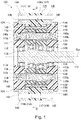
- Fig. 1 is a sectional view showing the speed reducer relating to the first embodiment along a main axis.
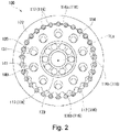
- Fig. 2 is a sectional view along a line II-II in Fig. 1 .
- the dimensions of the components in the drawings are shown enlarged or reduced as appropriate for ease of understanding. In the drawings, some parts that are not important for explaining the first embodiment are not shown.
- the reference numeral 100 indicates the speed reducer.
- Fig. 2 only shows one of the two external gears 114 for ease of understanding.
- the speed reducer 100 relating to the first embodiment is an eccentric oscillation speed reducer having an external gear and an internal gear meshing with each other. Oscillating the external gear causes one of the internal and external gears to rotate on its own axis, so that the generated rotational component is output to a driven device through an output member.
- the eccentric oscillation speed reducer 100 has an input shaft 112, an external gear 114, an internal gear 116, a first carrier 118, a second carrier 120, a casing 122, a first main bearing 124, a second main bearing 126, an inner pin 140 and a carrier pin 138.
- axial direction refers to the direction extending along the central axis (the main axis) 1La of the internal gear 116
- circumferential direction and “radial direction” respectively refer to the circumferential and radial directions of the circle centered on the central axis 1 La.
- the input side refers to one side in the axial direction (the right side in Fig. 1 ) and the non-input side or output side refers to the other side (the left side in Fig. 1 ).
- the first and second carriers 118 and 120 may be simply referred to as the carriers 118 and 120.
- the first and second main bearings 124 and 126 may be simply referred to as the main bearings 124 and 126.
- the input shaft 112 is rotatable around the center line when acted upon by rotational power input from a drive source.
- the speed reducer 100 relating to the present embodiment is a center crank type, where the rotational center line of the input shaft 112 is aligned with the central axis 1 La of the internal gear 116.
- the drive source is, for example, a motor, a gear motor or an engine.
- the input shaft 112 is an eccentric body having a plurality of eccentric portions 112a for oscillating the external gear 114. Having such a configuration, the input shaft (eccentric body) 112 is sometimes referred to as a crankshaft.
- the axial center of the eccentric portions 112a is eccentric to the rotational center line of the input shaft 112.
- the input shaft 112 includes two eccentric portions 112a adjacent to each other. The adjacent eccentric portions 112a are 180° out of phase in terms of eccentricity.
- the input shaft 112 is supported on the input side by the second carrier 120 via an input shaft bearing 134 and on the non-input side by the first carrier (shaft flange) 118 via an input shaft bearing 134.
- the input shaft 112 is supported such that it is rotatable relative to the first carrier 118 and the second carrier (hold flange) 120.
- the input shaft bearings 134 are not limited to any particular configurations, but are, for example, ball bearings with spherical rollers in the present embodiment.
- the internal gear 116 meshes with the external gear 114.
- the internal gear 116 includes an internal gear body 116a integrated into the casing 122, and outer pins (internal tooth pins) 117 disposed in pin grooves 116b formed in the internal gear body 116a and arranged at intervals in the circumferential direction.
- the outer pins 117 are cylindrical pin members rotatably supported on the internal gear body 116a.
- the outer pins 117 form the internal teeth of the internal gear 116.
- the number of outer pins 117 (the number of internal teeth) of the internal gear 116 is slightly (in this example, by one) greater than the number of external teeth of the external gear 11.
- the outer pins 117 are all shaped in the same manner.
- the radial dimension of the outer pins 117 remains constant along their entire length along the central axis 1La. All of the outer pins 117 run parallel to the central axis 1La.
- the outer pins 117 are all positioned in the same manner in the radial direction and in the axial direction along the central axis 1La, while being spaced away from each other in the circumferential direction.
- the internal gear body 116a and the casing 122 which are integrated to each other, are made of resin.
- the internal gear body 116a and the casing 122 can be made of a variety of resin.
- the internal gear body 116a and the casing 122 are made of polyacetal (POM).
- POM polyacetal
- the resin used to make the internal gear body 116a, the casing 122 and other constituent parts of the present embodiment may be resin containing reinforcing fibers such as glass or carbon fibers, resin without reinforcing fibers, lamination of a base material such as paper or fabric impregnated with resin.
- the resin used for the constituent parts of the present embodiment may be resin having thermally conductive fillers mixed therein.
- the outer pins 117 may be made of a material that has a higher thermal conductivity [W/(m ⁇ K)] and that is more resistant against wear than the resin material used for the internal gear body 116a.
- metals are introduced as an example thermally conductive material that is more resistant against wear than resin.
- the term "metals" include thermally conductive materials that are more resistant against wear than the above-listed resin.
- the outer pins 117 can be made of any material as long as it exhibits higher resistance against wear and higher thermal conductivity than the resin used to make the internal gear body 116a and can be made of metals, highly thermally conductive resin, non-metal materials and the like.
- the outer pins 117 may be, for example, made of resin having carbon nanotubes (CNTs), boron nitride nanotubes (BNNTs) mixed therein.
- the outer pins 117 relating to the present embodiment, shown in Figs. 1 and 2 may be made of iron-based metals such as bearing steel.
- the outer pins 117 can be solid or hollow.
- the outer pins 117 may have a multi-layered structure with a core material being wrapped in a surface material.
- one of the core and surface materials of the multi-layered structure of the outer pins 117 may be made of iron-based metals, and the other may be made of a copper- or aluminum-based metal.
- Such a structure can eliminate the trade-off between the mechanical and thermal characteristics.
- the core and surface materials of the multi-layered structure of the outer pins 117 one of them may be made of metals and the other may be made of resin.
- the outer pins 117 may be made of sintered metals.
- the speed reducer 100 has a plurality of external gears 114 provided in a one-to-one correspondence with the eccentric portions 112a.
- the external gears 114 are rotatably supported on the eccentric portions 112a via eccentric bearings 130.
- the external gears 114 each have ten through holes that are arranged at equal intervals and offset from the central axis of the external gears 114.
- the carrier pin holes 139 receive carrier pins 138.
- the remaining seven through holes serve as inner pin holes 141.
- the inner pin holes 141 receive inner pins 140.
- the carrier pin holes 139 may have the same diameter as the inner pin holes 141.
- the external gears 114 are made of resin, like the internal gear body 116a.
- the external gears 114 can be made of a variety of resin.
- the external gears 114 are located closer to the input shaft 112 than is the internal gear body 116a.
- the external gears 114 are made of, for example, PEEK.
- the present embodiment, however, is not limited to such, and the external gears 114 may be made of, for example, POM or other resins than PEEK.
- the carrier pin holes 139 and the inner pin holes 141 are at the same distance from the center in the radial direction and shaped like a circle having the same diameter.
- Corrugated teeth are formed on the outer periphery of the external gears 114.
- the external gears 114 oscillate within a plane to which the central axis of the external gears 114 is normal, such that the corrugated teeth move while keeping touching the internal gear 116.
- a gap is provided between the inner pins 140 and the inner pin holes 141 to absorb the oscillating component of the external gears 114.
- the inner pins 140 partially touch the inner wall surface of the inner pin holes 141.
- the carriers 118 and 120 sandwich the external gears 114 therebetween in the axial direction.
- the first carrier (shaft flange) 118 is located on the lateral portion of the external gears 114 on the non-input side.
- the second carrier (hold flange) 120 is located on the lateral portion of the external gears 114 on the input side.
- the first carrier (shaft flange) 118 is rotatably supported by the casing 122 via a first main bearing 124.
- the second carrier (hold flange) 120 is rotatably supported by the casing 122 via a second main bearing 126.
- the carriers 118 and 120 are shaped like a disc as a whole.
- the first carrier 118 rotatably supports the input shaft 112 via the input shaft bearings 134.
- the second carrier 120 rotatably supports the input shaft 112 via the input shaft bearings 134.
- the carrier pins 138 are coupled to the first carrier (shaft flange) 118 and to the second carrier (hold flange) 120 with bolts 138a.
- the inner pins 140 are coupled to the first carrier (shaft flange) 118 and to the second carrier (hold flange) 120 via, for example, bolts 140a made of iron-based metals.
- the first and second carriers 118 and 120 are coupled to each other via the carrier and inner pins 138 and 140.
- the carrier and inner pins 138 and 140 are positioned off the axial center of the external gears 114 in the radial direction and penetrate the external gears 114 in the axial direction.
- the carrier and inner pins 138 and 140 are provided as separate parts from the carriers 118 and 120. The present embodiment, however, is not limited to such.
- the carrier and inner pins 138 and 140 may be partly integrated into the carriers 118 and 120.
- One of the first carrier 118 and the casing 122 serves as an output member for outputting rotational power to a driven device, and the other serves as a stationary member fixedly attached to an external member for supporting the speed reducer 100.
- the output member is rotatably supported on the stationary member via the main bearings 124 and 126.
- the non-input-side end surface of the first carrier 118 may have a driven member, which is to be rotated by the speed reducer 100, coupled thereto with bolts or the like.
- the outer peripheral flange of the casing 122 may have a driven member, which is to be rotated by the speed reducer 100, coupled thereto with bolts or the like.
- the casing 122 is shaped like a hollow tube as a whole.
- the internal gear 116 is provided on the inner periphery of the casing 122.
- a flange or the like may be provided on the outer periphery of the casing 122.
- the casing 122 has a first metal ring 144 located on the non-input side of the casing 122 and a second metal ring 145 located on the input side of the casing 122.
- the first and second metal rings 144 and 145 are fixedly attached to and integrated into the casing 122.
- the first and second metal rings 144 and 145 may be fixedly attached to the casing 122 with a plurality of bolts arranged next to each other in the circumferential direction.
- first and second metal rings 144 and 145 may be simply referred to as the metal rings 144 and 145.
- the casing 122 has a depression receiving therein the first metal ring 144.
- the first metal ring 144 protrudes in the axial direction beyond the depression.
- the first metal ring 144 serves as the outer ring of the first main bearing 124.
- the first metal ring 144 may have the outer periphery flush with the outer periphery of the casing 122.
- the first metal ring 144 which serves as the outer ring of the first main bearing 124, is located on the output side of the casing 122.
- the first metal ring 144 is exposed on the output side of the casing 122.
- the portion of the first metal ring 144 that protrudes in the axial direction beyond the depression of the casing 122 constitutes an inner sliding surface 148 serving as the outer ring.
- the inner sliding surface 148 is in contact with the first carrier (shaft flange) 118.
- the first metal ring 144 is firmly fitted onto the casing 122, and the fit can be, for example, a clearance fit, an interference fit or a transition fit.
- the clearance may be determined by the difference in thermal expansion coefficient.
- the casing 122 has a depression for receiving therein the second metal ring 145.
- the second metal ring 145 protrudes in the axial direction beyond the depression.
- the second metal ring 145 serves as the outer ring of the second main bearing 126.
- the second metal ring 145 may have the outer periphery flush with the outer periphery of the casing 122.
- the second metal ring 145 which serves as the outer ring of the second main bearing 126, is located on the input side of the casing 122.
- the second metal ring 145 is exposed on the input side of the casing 122.
- the portion of the second metal ring 145 that protrudes in the axial direction beyond the depression of the casing 122 constitutes the inner sliding surface 148 serving as the outer ring.
- the inner sliding surface 148 is in contact with the second carrier (hold flange) 120.
- the second metal ring 145 is firmly fitted onto the casing 122, and the fit can be, for example, a clearance fit, an interference fit or a transition fit.
- the clearance may be determined by the difference in thermal expansion coefficient.
- the first main bearing 124 is arranged between the first carrier 118 and the casing 122.
- the second main bearing 126 is arranged between the second carrier 120 and the casing 122.
- the main bearings 124 and 126 of the present embodiment, shown in Figs. 1 and 2 are plain bearings.
- the main bearings 124 and 126 have the inner sliding surface 148 serving as part of the outer ring and an outer sliding surface 149 serving as part of the inner ring.
- the outer sliding surface 149 is formed on the outer peripheral surface of the carriers 118 and 120.
- the inner sliding surface 148 is formed on the inner peripheral surface of the metal rings 144 and 145.
- the inner sliding surface 148 serving as part of the outer ring of the main bearings 124 and 126 is made of a material having a higher thermal conductivity than the resin making the carriers 118 and 120 forming the outer sliding surface 149 serving as part of the inner ring.
- any material can be used to make the metal rings 144 and 145 serving as the outer ring of the main bearings 124 and 126 as long as the material exhibits a higher thermal conductivity than the resin of the carriers 118 and 120 serving as the inner ring and a higher strength than the resin of the carriers 118 and 120.
- the material used to make the metal rings 144 and 145 may be metallic or non-metallic materials.
- the metal rings 144 and 145 relating to the present embodiment may be made of copper- or aluminum-based metals, or iron-based metals such as bearing steel.
- the metal rings 144 and 145 can be solid or hollow.
- the metal rings 144 and 145 may have a multi-layered structure with a core material being wrapped in a surface material forming the inner sliding surface 148.
- one of the core and surface materials of the multi-layered structure of the metal rings 144 and 145 may be made of iron-based metals and the other may be made of copper- or aluminum-based metals.
- the metal rings 144 and 145 may be made of sintered metals.
- the inner and outer sliding surfaces 148 and 149 are outside the outer pins 117 in the radial direction.
- the first and second metal rings 144 and 145 both overlap the outer pins 117 when seen in the radial direction. This arrangement can contribute to maintain the strength of the casing 122 along the entire length.
- the inner pins 140 are inserted into the inner pin holes 141, which are formed in the external gears 114, with a clearance therebetween.
- the inner pins 140 are fitted at one end thereof into recesses 118a in the first carrier 118 and at the other end thereof into recesses 120b in the second carrier 120.
- the inner pins 140 are fixedly inserted into the recesses 118a and 120b with bolts 140a.
- the inner pins 140 may be press-fitted into the recesses 118a and 120b. In this case, the inner pins 140 may not be necessarily fixed using bolts or the like.
- the inner pins 140 are in contact with part of the inner pin holes 141, which are formed in the external gears 114.
- the inner pins 140 restricts the external gears 114 from rotating on their own axis and only allows the external gears 114 to oscillate.
- the inner pins 140 serve as a coupling member for transmitting power between the first and second carriers 118 and 120 and the external gears 114.
- the carrier pins 138 are inserted into the carrier pin holes 139, which are formed in the external gears 114, with a clearance therebetween.
- the carrier pins 138 are fitted at one end thereof into recesses 118c in the first carrier 118 and at the other end thereof into recesses 120c in the second carrier 120.
- the carrier pins 138 are fixedly inserted into the recesses 118c and 120c with bolts 138a.
- the carrier pins 138 may be press-fitted into the recesses 118c and 120c. In this case, the carrier pins 138 may not be necessarily fixed using bolts or the like.
- the carrier pins 138 are not in contact with the carrier pin holes 139 formed in the external gears 114. With such arrangement, the carrier pins 138 do not play role in restricting the external gears 114 from rotating on their own axis.
- the carrier pins 138 serve as a coupling member contributing only to couple together the first and second carriers 118 and 120.
- Speed reducers have seen an increase in its applications, including collaborative robots working closely with people. In order to expand the applications, it is desired to reduce the weight and noise of the speed reducers.
- Conventional speed reducers are made up by components made of iron-based metals. In order to diminish the weight, the components may be made of materials with low specific gravity. Favorable materials with low specific gravity include resin. On the other hand, if the components are made of resin, the components may experience temperature rise due to poorer heat dissipation and resultantly have shortened lifetime. For this reason, the materials of the components are desirably selected in consideration of the purposes of weight reduction and heat dissipation. Here, the weight reduction may lead to compromised strength, which needs to be avoided.
- the speed reducer 100 In the speed reducer 100, a large amount of heat is often generated inside the speed reducer 100, more specifically, around the main bearings 124 and 126, which are plain bearings. In addition, a large amount of heat is also often generated around the input shaft 112, which is rotatable at a relatively high speed. Furthermore, the speed reducer 100 may malfunction unless the inner pins 140 and external gears 114 maintain sufficient strength. As noted, the speed reducers experience a large temperature increase if the heat generated inside is dissipated outside less efficiently. The resin components experience a sudden drop in rigidity and strength as the temperature rises. Accordingly, the continued use of the less rigid and strong resin components may probably result in malfunction.
- one of the members that are movable relative to each other is made of a resin
- the other member is desirably made of a material exhibiting a higher resistance against wear and a higher thermal conductivity [W/(m ⁇ K)] than the resin member.
- the heat generated inside can be dissipated outside in a better manner than when the other member is made of a low-thermal-conductivity material.
- the members can achieve a longer lifetime than when the other member is made of a low-wear-resistance material.
- the material used to make the inner sliding surface 148 serving as the outer ring may be made of any material as long as it exhibits higher wear-resistance and thermal conductivity than the resin used to make the internal gear body 116a forming the outer sliding surface 149 serving as the inner ring.
- the inner sliding surface 148 can be made of, for example, metal, non-metal, and highly thermally conductive materials.
- the first and second metal rings 144 and 145, which constitute the inner sliding surface 148 of the present embodiment, and the outer pins 117 may be made of iron- and aluminum-based metals such as bearing steel, light metals such as aluminum, magnesium, beryllium, and titanium, or composites thereof. Alternatively, the first and second metal rings 144 and 145 and the outer pins 117 may be made of ceramics or other materials.
- the speed reducer 100 can achieve both light weight and sufficient mechanical strength.
- the input shaft 112 and the input shaft bearings 134 located between the first carrier 118 and the input shaft 112 receive high-speed rotation before it is slowed down. This means that the input shaft 112 and the input shaft bearings 134 experience a relatively large temperature rise and allow the rotation to be input only at low speed if they exhibit low resistance against heat.
- the input shaft bearings 134, input shaft 112 and eccentric bearings 130 may be made of metals, such as iron-based metals. This can prevent a drop in the allowable number of rotations input into them. Since the input shaft 112 is subjected to large torsional stress, the input shaft 112 is preferably made of a more rigid material than the first carrier 118.
- the input shaft 112 may be made of aluminum or iron-based metals with a higher torsional strength than aluminum, for example.
- the iron-based metals can include carbon steel, bearing steel, and stainless steel, any of which can be used depending on the desired characteristics.
- the carrier pins 138 are desirably highly rigid in order to reliably achieve sufficient coupling strength between the first and second carriers 118 and 120.
- the carrier pins 138 may be made of metals.
- the carrier pins 138 are made of a material that has higher wear-resistance and thermal conductivity than resin, for example, metals such as aluminum.
- the speed reducer 100 configured as described above operates.
- the eccentric portions 112a of the input shaft 112 rotate around the rotational center line passing through the input shaft 112 (the central axis 1La).
- the external gears 114 oscillate in such a manner that their own axial center rotates around the rotational center line of the input shaft 112.
- the meshing between the external gears 114 and the outer pins 117 of the internal gear 116 takes place at sequentially shifted positions.
- the first and second main bearings 124 and 126 are constituted by the first and second metal rings 144 and 145, and the first and second carriers 118 and 120, which account for the main portion of the weight of the speed reducer 100, are made of resin. This can contribute to successful weight reduction.
- the metal rings 144 and 145 forming the inner sliding surface 148 are made of a material exhibiting higher wear-resistance and thermal conductivity than the resin used to make the carriers 118 and 120 forming the outer sliding surface 149. This can help dissipating the heat generated in the speed reducer 100 more efficiently via the metal rings 144 and 145 and the outer pins 117. As a result, the present embodiment can prevent a temperature rise in the speed reducer 100 more effectively.
- the first and second metal rings 144 and 145 wrap the outer pins 117 when seen in the radial direction.
- This arrangement can contribute to maintain the strength of the casing 122 along the entire length in the axial direction. Therefore, the present embodiment can prevent deformation of the casing 122 and deformation of the carriers 118 and 120, and also prevent failure of the external gears 114. As a result, the present embodiment can maintain sufficient strength.
- the outer pins 117 are made of metals or the like. This can contribute to prevent the failure of the external gears 114 and to maintain sufficient strength.
- the inner and outer sliding surfaces 148 and 149 do not wrap the outer pins 117 when seen in the axial direction, and the inner and outer sliding surfaces 148 and 149 and the outer pins 117 are arranged substantially consecutively in the axial direction. With such arrangement, the thickness of the speed reducer 100 can be reduced while the speed reducer 100 maintains the strength. In other words, the dimension of the speed reducer 100 in the direction extending along the central axis 1 La can be reduced, so that the size reduction can be accomplished.
- the inner sliding surface 148 of the first and second metal rings 144 and 145 is close to the outer pins 117 in the radial direction. Accordingly, the heat transferred from the main bearings 124 and 126, which are sliding bearings, to the first and second metal rings 144 and 145 can be dissipated outside, so that the speed reducer 100 can achieve better heat dissipation.
- the speed reducer 100 may fail. According to the present embodiment, however, improved heat dissipation can be achieved. This can prevent the heat from being contained in the speed reducer 100, thereby preventing problems from occurring.
- the outer pins 117 are made of metals or the like, the outer pins 117 can release the heat transferred from the vicinity of the main bearings 124 and 126, to prevent a local temperature rise. As a result, the speed reducer 100 can achieve improved heat dissipation.
- the speed reducer 100 can be reliably configured, while keeping sufficient heat dissipation and achieving further weight reduction.
- Fig. 3 is a sectional view showing the speed reducer relating to the second embodiment along a direction extending along a main axis.
- the present embodiment is different from the first embodiment in terms of the main bearings.
- the other components relating to the second embodiment have counterparts in the first embodiment, and are thus assigned with the same reference signs and not described now.
- the first metal ring 144 of the first main bearing 124 is provided on the first carrier (shaft flange) 118.
- the first metal ring 144 has the outer periphery constituting the outer sliding surface 149 of the main bearing 124.
- the first carrier (shaft flange) 118 has a depression for receiving therein the first metal ring 144.
- the first metal ring 144 is adjacent to the outer pins 117 in the axial direction.
- the first metal ring 144 serves as the inner ring of the first main bearing 124.
- the first metal ring 144 may have the outer periphery flush with the outer periphery of the first carrier (shaft flange) 118.
- the first metal ring 144 which serves as the inner ring of the first main bearing 124, is located on the input side in the first carrier (shaft flange) 118.
- the outer peripheral portion of the first metal ring 144 which is flush with the outer periphery of the first carrier (shaft flange) 118, forms the outer sliding surface 149 serving as the inner ring.
- the outer sliding surface 149 of the first metal ring 144 is in contact with the casing 122.
- the first metal ring 144 is firmly fitted onto the first carrier (shaft flange) 118, and the fit can be, for example, a clearance fit, an interference fit or a transition fit.
- the clearance may be determined by the difference in thermal expansion coefficient.
- the inner peripheral surface of the casing 122 in contact with the outer sliding surface 149 forms the inner sliding surface 148 serving as the outer ring of the first main bearing 124. Therefore, the outer ring of the first main bearing 124 is integrated with the casing 122.
- the second metal ring 145 of the second main bearing 126 is provided on the second carrier (hold flange) 120 in the speed reducer 100 of the present embodiment, as shown in Fig. 3 .
- the second metal ring 145 has the outer periphery constituting the outer sliding surface 149 of the main bearing 126.
- the second carrier (hold flange) 120 has a depression for receiving therein the second metal ring 145.
- the second metal ring 145 is adjacent to the outer pins 117 in the axial direction.
- the second metal ring 145 serves as the inner ring of the second main bearing 126.
- the second metal ring 145 may have the outer periphery flush with the outer periphery of the second carrier (hold flange) 120.
- the second metal ring 145 which serves as the inner ring of the second main bearing 126, is located on the output side in the second carrier (hold flange) 120.
- the outer peripheral portion of the second metal ring 145 which is flush with the outer periphery of the second carrier (hold flange) 120, forms the outer sliding surface 149 serving as the inner ring.
- the outer sliding surface 149 of the second metal ring 145 is in contact with the casing 122.
- the second metal ring 145 is firmly fitted onto the second carrier (hold flange) 120, and the fit can be, for example, a clearance fit, an interference fit or a transition fit.
- the clearance may be determined by the difference in thermal expansion coefficient.
- the metal rings 144 and 145 of the main bearings 124 and 126 can be alternatively configured to radially externally cover the entire outer periphery of the carriers 118 and 120.
- the inner and outer sliding surfaces 148 and 149 are respectively made of resin and metals. Accordingly, the second embodiment can produce the same effects as the first embodiment.
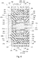
- Fig. 4 is a sectional view showing the speed reducer relating to the third embodiment along a direction extending along a main axis.
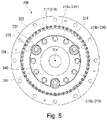
- Fig. 5 is a sectional view along a line V-V in Fig. 4 .
- the reference numeral 200 indicates the speed reducer.
- the speed reducer 200 relating to the third embodiment is an eccentric oscillation speed reducer having an external gear and an internal gear meshing with each other. Oscillating the external gear causes one of the internal and external gears to rotate on its own axis, so that the generated rotational component is output to a driven device through an output member.
- the speed reducer 200 of the present embodiment is different from the speed reducer 100 relating to the first embodiment in that two external gears 214 are assembled together with a phase difference of 180 degrees, as shown in Figs. 4 and 5 . Except for this, the speed reducer 200 relating to the third embodiment is the same as the speed reducer 100 relating to the first embodiment.
- the speed reducer 200 relating to the third embodiment includes an input shaft 212, external gears 214, an internal gear 216, a first carrier 218, a second carrier 220, a casing 222, a first main bearing 224, a second main bearing 226, inner pins 240 and carrier pins 238.
- main axis direction refers to the direction extending along a central axis 2La of the internal gear 216
- the expressions "circumferential direction” and “radial direction” respectively refer to the circumferential and radial directions of the circle centered on the central axis 2La.
- the input side refers to one side in the axial direction (the right side in Fig. 4 ) and the non-input side refers to the other side (the left side in Fig. 4 ).
- the first and second carriers 218 and 220 may be simply referred to as the carriers 218 and 220.
- the first and second main bearings 224 and 226 may be simply referred to as the main bearings 224 and 226.
- the input shaft 212 is rotatable around the rotational center line when acted upon by rotational power input from a drive device (not shown).
- the speed reducer 200 relating to the third embodiment is a center crank type, where the rotational center line of the input shaft 212 is aligned with the central axis 2La of the internal gear 216.
- the drive device is, for example, a motor, a gear motor or an engine.
- the input shaft 212 relating to the present embodiment is an eccentric shaft having a plurality of eccentric portions 212a for oscillating the external gears 214. Having such a configuration, the input shaft (eccentric body) 212 is sometimes referred to as a crankshaft.
- the axial center of the eccentric portions 212a is eccentric to the rotational center line of the input shaft 212.
- two eccentric portions 212a are adjacent to each other. The adjacent eccentric portions 212a are 180° out of phase in terms of eccentricity.
- the input shaft 212 is supported on the input side by a second cover 223 via an input shaft bearing 234 and on the non-input side by the first carrier 218 via an input shaft bearing 234.
- the input shaft 212 is supported such that it is rotatable relative to the first carrier 218 and the second cover 223.
- the input shaft bearings 234 are not limited to any particular configurations, but can be ball bearings with spherical rollers in the present embodiment. Preload may be applied to the input shaft bearings 234, but no preload is applied in the present example.
- the internal gear 216 meshes with the external gears 214.
- the internal gear 216 includes an internal gear body 216a integrated into the casing 222 and outer pins (internal tooth pins) 217 disposed in pin grooves 216b formed in the internal gear body 216a at intervals in the circumferential direction.
- the outer pins 217 are cylindrical pin members rotatably supported on the internal gear body 216a.
- the outer pins 217 form the internal teeth of the internal gear 216.
- the number of outer pins 217 (the number of internal teeth) of the internal gear 216 is slightly (in this example, by one) greater than the number of external teeth of the external gears 214.
- the internal gear body 216a is made of resin.
- the internal gear body 216a can be made of a variety of resin.
- the internal gear body 216a is made of, for example, polyacetal (POM).
- POM polyacetal
- PAEK polyaryletherketones
- PEEK polyetheretherketone
- the resin used to make the internal gear body 116a and other constituent parts of the present embodiment may be resin containing reinforcing fibers such as glass or carbon fibers, a resin without reinforcing fibers, a lamination of a base material such as paper or fabric impregnated with resin.
- the resin used for the constituent parts of the present embodiment may be a resin having thermally conductive fillers mixed therein.
- the thermally conductive fillers include, for example, nano-order fillers, powders of ceramics such as aluminum oxide and aluminum nitride, and powders of metals such as aluminum, copper and graphite.
- the speed reducer 200 In the speed reducer 200, a large amount of heat is often generated inside, in particular, around the input shaft 212, which is rotatable at a relatively high speed.
- the speed reducer 200 experiences a large temperature rise if the heat generated inside is dissipated outside less efficiently.
- the resin components experience a sudden drop in strength as the temperature rises. Accordingly, the continued use of the resin components may probably result in breakage.
- one of the gears that mesh with each other is made of a resin
- the other gear is desirably made of a material exhibiting a higher thermal conductivity [W/(m ⁇ K)] than the resin gear.
- the outer pins 217 are made of a material that has a higher thermal conductivity than the resin material used for the internal gear body 216a. In this case, the heat generated inside can be dissipated outside in a better manner than when the outer pins 217 are made of a low thermal conductivity material.
- the outer pins 217 can be made of any material as long as it exhibits a higher thermal conductivity than the resin used to make the internal gear body 216a and can be made of metal, highly thermally conductive resin, non-metal materials and the like. Highly thermally conductive resin include resin having thermally conductive fillers mixed therein.
- the outer pins 217 may be, for example, made of resin having carbon nanotubes (CNTs), boron nitride nanotubes (BNNTs) mixed therein.
- the outer pins 217 relating to the present embodiment may be made of iron-based metals such as bearing steel.
- the outer pins 217 can be solid or hollow.
- the outer pins 217 may have a multi-layered structure with a core material being wrapped in a surface material.
- one of the core and surface materials of the multi-layered structure of the outer pins 217 may be made of iron-based metals, and the other may be made of copper- or aluminum-based metals.
- Such a structure can eliminate the trade-off between the mechanical and thermal characteristics.
- the core and surface materials of the multi-layered structure of the outer pins 217 one of them may be made of metals, and the other may be made of resin.
- the outer pins 117 may be made of sintered metals.
- the external gears 214 are provided in a one-to-one correspondence with the eccentric portions 212a.
- the external gears 214 are rotatably supported on the eccentric portions 212a via eccentric bearings 230.
- the external gears 214 have twelve through holes arranged at equal intervals and offset from the axis of the external gears 214. Three of the twelve through holes, which are at equal intervals of 120 degrees around the axis of the external gears 214, serve as carrier pin holes 239.
- the carrier pin holes 239 receive carrier pins 238.
- the remaining nine through holes serve as inner pin holes 241.
- the inner pin holes 241 receive inner pins 240.
- the diameter of the carrier pin holes 239 is greater than that of the inner pin holes 241.
- the present embodiment, however, is not limited to such, and the carrier pin holes 239 may have the same diameter as the inner pin holes 241.
- the external gears 214 are made of resin.
- the external gears 214 can be made of a variety of types of resin.
- the external gears 214 may be made of resin that have a higher heat resistance temperature than the internal gear body 216a.
- the external gears 214 are made of, for example, PEEK.
- the carrier pin holes 239 and the inner pin holes 241 are at the same distance from the center in the radial direction and shaped like a circle.
- Corrugated teeth are formed on the outer periphery of the external gears 214.
- the external gears 214 oscillate within a plane to which the axis of the external gears 214 is normal, such that the corrugated teeth move while keeping touching the internal gear 216.
- a gap is provided between the inner pins 240 and the inner pin holes 241 to absorb the oscillating component of the external gears 214.
- the inner pins 240 partially touch the inner wall surface of the inner pin holes 241.
- the carriers 218 and 220 are arranged on the lateral portion of the external gears 214 in the axial direction.
- the first carrier (shaft flange) 218 is located on the non-input-side lateral portion of the external gears 214.
- the second carrier (hold flange) 220 is located on the input-side lateral portion of the external gears 214.
- the first and second carriers 218 and 220 are rotatably supported by the casing 222 via first and second main bearings 224 and 226.
- the carriers 218 and 220 are shaped like a disc as a whole.
- the first carrier 218 rotatably supports the input shaft 212 via an input shaft bearing 234.
- the second carrier 220 may be configured to support the input shaft 212 via an input shaft bearing 234, but does not support the input shaft bearing 234 and the input shaft 212 in the present embodiment.
- the first and second carriers 218 and 220 are coupled to each other via the carrier and inner pins 238 and 240.
- the carrier and inner pins 238 and 240 are positioned offset from the axial center of the external gears 214 in the radial direction and penetrate the external gears 214 in the axial direction.
- the carrier and inner pins 238 and 240 are provided as separate parts from the carriers 218 and 220. The present embodiment, however, is not limited to such.
- the carrier and inner pins 238 and 240 may be partly integrated into the carriers 218 and 220.
- One of the first carrier 218 and the casing 222 serves as an output member for outputting rotational power to a driven device, and the other serves as a stationary member fixedly attached to an external member for supporting the speed reducer 200.
- the output member is rotatably supported on the stationary member via the main bearings 224 and 226.
- the output member is the first carrier 218, and the stationary member is the casing 222.
- the non-input-side end surface of the first carrier 218 may have a driven member 250, which is to be rotated by the speed reducer 200, coupled thereto with bolts 250b.
- the bolts 250b relating to the present embodiment may be made of iron-based metals.
- the casing 222 is shaped like a hollow tube as a whole.
- the internal gear 216 is provided on the inner periphery of the casing 222.
- a flange or the like may be provided on the outer periphery of the casing 222, but no flange is provided in the present example.
- the casing 222 has a first cover 221 covering the casing 222 on the non-input side and a second cover 223 covering the casing 222 on the input side.
- the first and second covers 221 and 223 are fixedly attached to the casing 222 with a plurality of bolts arranged next to each other in the circumferential direction.
- the casing 222 has a depression for receiving therein the input side of the outer ring of the first main bearing 224.
- the first cover 221 has a depression for receiving therein part of the non-input side of the outer ring of the first main bearing 224.
- the outer ring of the first main bearing 224 is supported by and sandwiched between the casing 222 and the first cover 221 in the axial direction.
- the casing 222 has a depression for receiving therein the non-input side of the outer ring of the second main bearing 226.
- the second cover 223 has a depression for receiving therein part of the input side of the outer ring of the second main bearing 226.
- the outer ring of the second main bearing 226 is supported by and sandwiched between the casing 222 and the second cover 223 in the axial direction.
- the second cover 223 has another depression for receiving therein the outer ring of the input-side input shaft bearing 234.
- the second cover 223 rotatably supports the input shaft 212 on the input side thereof via the input shaft bearing 234.
- the first main bearing 224 is arranged between the first carrier 218 and the casing 222.
- the second main bearing 226 is arranged between the second carrier 220 and the casing 222.
- the main bearings 224 and 226 relating to the present embodiment respectively have metal rings 244 and 245 forming the inner sliding surface 248.
- the metal rings 244 and 245 rotatably supports the carriers 218 and 220.
- the main bearings 224 and 226 are plain bearings.
- the main bearings 224 and 226 have (i) the metal rings 244 and 245 forming the inner sliding surface 248 serving as the outer ring and (ii) an outer sliding surface 249 serving as the inner ring.
- the outer sliding surface 249 is formed on the outer peripheral surface of the carriers 218 and 220.
- the metal rings 244 and 245 serving as the outer ring are firmly fitted onto the casing 222, and the fit can be, for example, a clearance fit, an interference fit or a transition fit. The clearance may be determined by the difference in thermal expansion coefficient. Pressure may be applied to the main bearings 224 and 226, but no pressure is applied in the present example.
- the metal rings 244 and 245 serving as the outer ring of the main bearings 224 and 226 are made of a material having a higher thermal conductivity than the resin used for the internal gear body 216a. Furthermore, the metal rings 244 and 245 are in contact with the outer pins 217 in the axial direction. As shown in Fig. 4 , the end of the metal rings 244 and 245 may be in direct contact with the end of the outer pins 217. The present embodiment, however, is not limited to such, and the end of the metal rings 244 and 245 may be in contact with the end of the outer pins 217 with a spacer being provided therebetween in the axial direction.
- the spacer may be made of a material exhibiting a higher thermal conductivity than the resin used for the internal gear body 216a.
- the metal rings 244 and 245 and the outer pins 217 can be made of any material as long as it exhibits higher thermal conductivity than the resin used to make the internal gear body 216a and can be made of metal, highly thermally conductive resin, non-metal materials and the like.
- the metal rings 244 and 245 and the outer pins 217 relating to the present embodiment may be made of iron-based metals such as bearing steel.
- the first carrier 218 can be made of any material as long as it exhibits higher thermal conductivity than the resin used to make the internal gear body 216a and can be made of metal, highly thermally conductive resin, non-metal materials and the like. In order to achieve both light weight and sufficient mechanical strength, the first carrier 218 may be made of light metals (metals with a specific gravity of 4, 5 or less) such as aluminum, magnesium, beryllium and titanium or a combination of these. The first carrier 218 relating to the present embodiment is made of aluminum-based metals. In this way, the first carrier 218 can be made of a metal material with a lower specific gravity than is the input shaft 212.
- the second carrier 220 can be made of metals or various types of resin.
- the second carrier 220 is made of POM, for example. In this way, the second carrier 220 can achieve a reduced weight.
- the second carrier 220 is not in direct contact with the input shaft bearing 234 but arranged with a space being provided therebetween.
- the second carrier 220 may be made of a material having a higher thermal conductivity than the resin used for the internal gear body 216a. This can contribute to further improve the heat dissipation.
- the inner pins 240 are inserted into the inner pin holes 241, which are formed in and penetrate the external gears 214, with a gap therebetween.
- the inner pins 240 are fitted at one end thereof into recesses 218a in the first carrier 218 and at the other end thereof into recesses 220b in the second carrier 220.
- the inner pins 240 are press-fitted in the recesses 218a and 220b and not secured using bolts or the like.
- the inner pins 240 are in contact with part of the inner pin holes 241, which are formed in the external gears 214. With such arrangement, the inner pins 240 restricts the external gears 214 from rotating on their own axis and only allows the external gears 114 to oscillate.
- the inner pins 240 serve as a coupling member playing a role in transmitting power between the first and second carriers 218 and 220 and the external gears 214.
- the carrier pins 238 are inserted into the carrier pin holes 239, which are formed in the external gears 214, with a gap therebetween.
- the carrier pins 238 are fitted at one end thereof into recesses 218c in the first carrier 218 and at the other end thereof into recesses 220c in the second carrier 220.
- the carrier pins 238 are press-fitted in the recesses 218c and 220c and not secured using bolts or the like.
- the carrier pins 238 are surrounded by tubular spacers 237.
- the spacers 237 touch, at one end thereof, the first carrier 218 and, at the other end thereof, the second carrier 220.
- the spacers 237 are designed to keep an appropriate distance in the axial direction between the first carrier 218 and the second carrier 220.
- the carrier pins 238 and spacers 237 are not in contact with the carrier pin holes 239 formed in the external gears 214, so that they do not contribute to restrain the external gears 214 from rotating on their own axis.
- the carrier pins 238 serve as a coupling member contributing only to couple together the first and second carriers 218 and 220.
- the constituents of the speed reducer relating to the present embodiment are desirably made of a material selected in consideration of the purposes of weight reduction and heat dissipation.
- speed reducers have seen an increase in its applications including collaborative robots working closely with people. For this reason, it is desired to reduce the weight and noise of the speed reducers.
- Conventional speed reducers are constituted by parts made of iron-based metals.
- the constituents may be made of materials with low specific gravity. Suitable materials with low specific gravity include resin.
- the components are made of resin, they may experience a temperature rise due to poorer heat dissipation and resultantly have shortened lifetime.
- the input shaft 212 and the input shaft bearings 234 located between the first carrier 218 and the input shaft 212 receive high-speed rotation input thereto before it is slowed down.
- the input shaft bearings 234, input shaft 212 and eccentric bearings 230 may be made of metals, such as iron-based metals. This can prevent a drop in the allowable number of rotations input into them. Since the input shaft 212 is subjected to large torsional stress, the input shaft 212 is preferably made of a more rigid material than the first carrier 218.
- the input shaft 212 is made of iron-based metals with a higher torsional strength than aluminum.
- the iron-based metals that can be used to make the constituents of the speed reducer relating to the present embodiment can include carbon steel, bearing steel, and stainless steel, any of which can be used depending on the desired characteristics.
- the carrier pins 238 are desirably highly rigid in order to reliably achieve sufficient coupling strength between the first and second carriers 218 and 220.
- the carrier pins 238 may be made of metals and the spacers 237 may be made of resin in order to achieve reduced weight.
- the carrier pins 238 are made of iron-based metals and the spacers 237 are made of POM.
- the casing 222 is integrated with the internal gear body 216a and may be made of the same material as the internal gear body 216a.
- the first and second covers 221 and 223 may be made of resin.
- the first and second covers 221 and 223 may be made of the same resin or different types of resin.
- the first and second covers 221 and 223 may be made of POM, for example.
- the eccentric portions 212a of the input shaft 212 rotate around the rotational center line of the input shaft 212.
- the external gears 214 oscillate in such a manner that their own axial center rotates around the rotational center line of the input shaft 212.
- the meshing between the external gears 214 and the outer pins 217 of the internal gear 216 takes place at sequentially shifted positions.
- the main bearings 224 and 226 have no metal constituents heavier than resins, except for the metal rings 244 and 245. Thus, the speed reducer 200 can achieve further weight reduction.
- the speed reducer 200 relating to the present embodiment can produce the same effects as the speed reducers relating to the above-described embodiments.
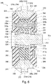
- Fig. 6 is a sectional view showing the speed reducer relating to the fourth embodiment along the axial direction.
- the present embodiment is different from the first embodiment in terms of the main bearings.
- the other components relating to the fourth embodiment have counterparts in the first embodiment, and they are assigned with the corresponding reference signs with the digit in the hundreds place is 3 in place of 1, and not described now.
- a casing 322 has an inner sliding surface 348 integrated therewith, serving as the outer ring of first and second main bearings 324 and 326.
- the casing 322 is entirely made of a material exhibiting higher wear-resistance and higher thermal conductivity than the resin used to make an outer sliding surface 349 serving as the inner ring of the first and second main bearings 324 and 326.
- the casing 322 is made of metals.
- the first and second main bearings 324 and 326 may be simply referred to as the main bearings 324 and 326.
- the inner and outer sliding surfaces 348 and 349 are shaped such that they have a larger diameter at a position away from external gears 314 than at a position close to the external gears 314 in the direction extending along the central axis 3La.
- the inner and outer sliding surfaces 348 and 349 form an angle of, for example, 30° to 60° relative to the central axis 3La.
- the present embodiment is, however, not limited to such, and the inner and outer sliding surfaces 348 and 349 may form an angle in the range of 40°to 50°, more preferably 45° relative to the central axis 3La.
- the inner and outer sliding surfaces 348 and 349 form an angle of, for example, 45° to 40° relative to the central axis 3La.
- first and second carriers (shaft flange) 318 and (hold flange) 320 which are made of resin. This can save the first and second carriers 318 and 320 from deformation.
- the first carrier (shaft flange) 318 and the second carrier (hold flange) 320 which are made of resin, can be prevented from becoming too thin in the axial direction near their outer edge.
- the casing 322 and the first carrier (shaft flange) 318 tightly seal the internal space of the speed reducer 300 via the first main bearing 324.
- the casing 322 and the second carrier (hold flange) 320 tightly seal the internal space of the speed reducer 300 via the second main bearing 326.
- the external gears 314 and the outer pins (internal tooth pins) 317 are housed in the internal space of the speed reducer 300.
- the main bearings 324 and 326 are plain bearings.
- the internal space of the speed reducer 300 is tightly sealed by the inner and outer sliding surfaces 348 and 349.
- Fig. 6 does not show the carrier pins.
- the casing 322 is entirely made of a thermally conductive material that exhibits a higher wear resistance than resin, for example, metals. This allows the heat generated by the main bearings 324 and 326 to be quickly dissipated outside through the casing 322. As a result, the temperature rise of the speed reducer 300 can be effectively prevented.
- the constituents other than the casing 322, the inner pins 340 and the drive gear 313 are made of resin, the speed reducer 300 can achieve reduced weight.
- the casing 322 is made of metals, the speed reducer 300 can maintain sufficient strength and rigidity.
- the inner and outer sliding surfaces 348 and 349 form an angle in the above-described range relative to the central axis 3La. This means that the inner and outer sliding surfaces 348 and 349 can have an increased area without causing an increase in the thickness of the speed reducer 300 in the axial direction. Furthermore, since the present embodiment can prevent deformation of the casing 322, the first carrier (shaft flange) 318 and the second carrier (hold flange) 320, the speed reducer 300 can be strong enough to prevent any malfunctions. As a result, the speed reducer 300 can avoid failures or the like and can stably keep operating.
- the speed reducer 300 relating to the present embodiment can produce the same effects as the speed reducers relating to the above-described embodiments.
- Fig. 7 is an enlarged sectional view showing a portion of the speed reducer relating to the fifth embodiment that is near the main bearings, obtained by cutting the speed reducer along the axial direction.
- the present embodiment is different from the fourth embodiment described above in terms of the main bearings. Except for this difference, the present embodiment includes the same constituents as in the fourth embodiment, which are denoted by the same reference numerals and are not described here.
- the inner and outer sliding surfaces 348 and 349 of the main bearings 324 and 326 bulge out or project in the direction extending along the central axis 3La.
- one of the inner and outer sliding surfaces 348 and 349 may bulge out or project in the direction along the central axis 3La.
- the inner and outer sliding surfaces 348 and 349 preferably touch each other along the entire surface, so that they slidably support each other with touching each other by a large area. This ideal condition, however, may encounter difficulties due to distortions caused by the manufacturing process. This can result in backlash, which may cause the speed reducer 300 to fail. To prevent the speed reducer 300 from failing, the inner and outer sliding surfaces 348 and 349 include crush allowance as precautions.
- the crush allowance of the inner and outer sliding surfaces 348 and 349 can be a projection having a curved cross-section, as shown in Fig. 7 .
- the inner and outer sliding surfaces 348 and 349 contact each other over a range determined by the crush allowance. Accordingly, the range over which they touch each other can be reliably acquired.
- This can prevent manufacturing errors from keeping the inner and outer sliding surfaces 348 and 349 away from each other, as a result of which the inner and outer sliding surfaces 348 and 349 can reliably touch each other at the middle or in the vicinity thereof in the axial direction. Accordingly, the first carrier (shaft flange) 318 and the second carrier (hold flange) 320 can operate in a more stable manner relative to the casing 322.
- the present embodiment can prevent deformation of the casing 322, the first carrier (shaft flange) 318 and the second carrier (hold flange) 320, the speed reducer 300 can be strong enough to prevent any malfunctions. In addition, the temperature rise experienced by the main bearings 324 and 326 can be also prevented.
- the speed reducer 300 relating to the present embodiment can produce the same effects as the speed reducers relating to the above-described embodiments.
- Fig. 8 is a sectional view showing a casing constituting an inner sliding surface of a main bearing of the speed reducer relating to the sixth embodiment of the present invention.
- the present embodiment is different from the fourth embodiment described above in terms of the main bearings. Except for this difference, the present embodiment includes the same constituents as in the fourth embodiment, which are denoted by the same reference numerals and are not described here.
- a casing 322 forms an inner sliding surface 348 with grooves 360 formed therein.
- the grooves 360 which are formed in the inner sliding surface 348, include radial grooves (groove) 361 extending in the radial direction and circumferential grooves (grooves) 362 and 363 extending in the circumferential direction.
- the radial grooves 361 are formed on the inner sliding surface 348 and spaced away from each other in the circumferential direction.
- the radial grooves 361 may be arranged at equal intervals in the circumferential direction, for example.
- the circumferential grooves 362 are near the middle of the inner sliding surface 348 in the axial direction.
- the circumferential grooves 363 are formed in the inner sliding surface 348 near the external gear 314 in the axial direction.
- the radial grooves 361 are not closer to the external gears 314 than are the circumferential grooves 363 in the axial direction.
- the radial grooves 361 extend to the edge of the inner sliding surface 348 in a direction away from the external gear 314 in the axial direction, to become in communication with the outside.
- the circumferential grooves 362 and 363 continuously extend in the circumferential direction of the inner sliding surface 348, making a full circle.
- the radial grooves 361 are connected to the circumferential grooves 363 such that they terminate in the circumferential grooves 363.
- no other grooves are formed between the input shaft 312 and the circumferential grooves 363. This means that the grooves 360 are separated from the outer pins 317 and not in contact with the outer pins 317.
- the grooves 360 may be all equal in depth and width, or the circumferential grooves 362 and 363 may be larger than the radial grooves 361.
- the grooves 360 can catch any foreign matter such as dust and particles that enter between the inner sliding surface 348 and the outer sliding surface 349. This can prevent foreign matters from entering the inner space within the speed reducer 300. In other words, the present embodiment can prevent foreign substances such as dust and particles from affecting how the external gears 314, outer pins 317 and the like work. In addition, the grooves 360 can catch excessive grease, lubricant or the like between the inner sliding surface 348 and the outer sliding surface 349.
- the speed reducer 300 relating to the present embodiment can produce the same effects as the speed reducers relating to the above-described embodiments.
- Fig. 8 is an enlarged sectional view showing the casing 322 to indicate a relation between the grooves 360 and the crush allowance of the inner sliding surface 348 in the speed reducer 300 relating to the sixth embodiment.
- Fig. 10 is a sectional view showing the casing 322 to indicate another example of the relation between the grooves 360 and the crush allowance of the inner sliding surface 348 in the speed reducer 300 relating to the sixth embodiment.
- a plurality of projections to serve as crush allowance having an arc-shaped cross-section are formed on the inner sliding surface 348, and grooves can be formed between the projections.
- the casing 322 has two parallel ridges running in the circumferential direction and having an arc-shaped cross-section, and the space between the circumferential protrusions can serve as the circumferential grooves 363.
- the portion of the inner sliding surface 348 that is radially close to the input shaft 312 has curved ridges 348a.
- the portion of the inner sliding surface 348 that is radially close to the outer peripheral edge of the casing 322 has curved ridges 348b.
- the ridges 348a and 348b are formed such that they have substantially the same curvature in the cross-section. Between the ridges 348a and 348b, the circumferential grooves 363 are formed. In this way, a crush allowance can be provided on the inner sliding surface 348, which improves the stability of operation and prevents contamination inside the speed reducer 300.
- the curvature of the ridges 348a in the cross-section can be greater than that of the ridges 348b in the cross-section.
- the circumferential grooves 363 can be formed at a position further closer to the input shaft 312 in the radial direction.
- the grooves 360 are formed on the inner sliding surface 348 of the casing 322.
- the grooves can be formed on the outer sliding surface 349, for example.
- the outer sliding surface 349 is preferably made of metals, instead of resin.
- the inner sliding surface 348 can be made of resin.
- the carriers 318 and 320 can have metal rings provided thereon, and the outer sliding surface 349 can have grooves formed therein.
- Fig. 11 is a sectional view showing the speed reducer relating to the seventh embodiment along the axial direction.
- Fig. 12 is a sectional view along the line XII-XII in Fig. 11 .
- the reference numeral 400 indicates the speed reducer.
- the eccentric oscillation speed reducer 400 relating to the present embodiment is applied as a speed reducer to, for example, swivels of robots such as revolving drums and arm joints and swivels of various types of machine tools such as collaborative robots.
- the speed reducer 400 rotates, for example, at speeds from 80 rpm to 200 rpm, when used.
- a crankshaft (eccentric body) 410 is rotated.
- the first and second external gears 414 and 416 are oscillatorily rotated. In this way, the input rotation is slowed down, and the reduced rotations can be output.
- the speed reducer 400 includes a casing (outer tube) 422, a carrier 404, an input shaft 408, a plurality of (for example, three) crankshafts 410, a first external gear 414, a second external gear 416 and a plurality of (for example, three) transmission gears 420.
- the casing 422 forms the outer surface of the speed reducer 400 and has a substantially cylindrical shape.
- a large number of pin grooves 422b are formed on the inner peripheral surface of the casing 422.
- Each pin groove 422b extends in the axial direction of the casing 422 and has a semicircular sectional shape when cut along the plane orthogonal to the axial direction.
- the pin grooves 422b are arranged at regular intervals and next to each other in the circumferential direction on the inner peripheral surface of the casing 422.
- the casing 422 has a large number of internal tooth pins (outer pins) 417.
- Each internal tooth pin 417 is attached in a corresponding one of the pin grooves 422b. More specifically, each internal tooth pin 417 is fitted in the corresponding pin groove 422b and retained therein such that it extends in the axial direction of the casing 422. In this manner, the internal tooth pins 417 are at equal intervals in the circumferential direction of the casing 422.
- the internal tooth pins 417 mesh with first external teeth 414a of the first external gear 414 and second external teeth 416a of the second external gear 416.
- the internal tooth pins 417 form an internal gear 417A.
- the carrier 404 is housed within the casing 422 while being aligned with the casing 422.
- the carrier 404 is rotatable relative to the casing 422 about the same axis. Specifically, the carrier 404 is positioned inside the casing 422 in the radial direction.
- the carrier 404 is supported by first and second main bearings 424 and 426, which are spaced away from each other in the axial direction, on the casing 422 such that the carrier 404 and the casing 422 are rotatable relative to each other.
- the first and second main bearings 424 and 426 may be simply referred to as the main bearings 424 and 426.
- the carrier 404 includes a base and a second carrier (hold flange) 404b.
- the base has a first carrier (shaft flange) 404a and a plurality of (for example, three) shaft portions 404c.
- the first carrier 404a is positioned near one of the ends of the casing 422 in the axial direction.
- the first carrier 404a has a through hole 404d formed at the radial center thereof.
- a plurality of (for example, three) crankshaft mounting holes 404e (hereinafter referred to simply as “mounting holes 404e") are arranged next to each other at equal intervals in the circumferential direction.
- the second carrier 404b is positioned away from the first carrier 404a in the axial direction and near the other of the ends of the casing 422 in the axial direction.
- the second carrier 404b has a through hole 404f formed at the radial center thereof.
- a plurality of (for example, three) crankshaft mounting holes 404g (hereinafter referred to simply as "mounting holes 404g") are provided.
- the mounting holes 404g are positioned correspondingly to the mounting holes 404e formed in the first carrier 404a.
- a closed space is defined by the inner surfaces of the second and first carriers 404b and 404a and the inner peripheral surface of the casing 422.
- the three shaft portions 404c are integrated with the first carrier 404a.
- the shaft portions 404c extend linearly from one of the main surfaces (the inner main surface) of the first carrier 404a toward the second carrier 404b.
- the three shaft portions 404c are arranged next to each other at equal intervals in the circumferential direction (see Fig. 12 ).
- the shaft portions 404c are fastened to the second carrier 404b with bolts 404h (see Fig. 11 ). In this manner, the first carrier 404a, the shaft portions 404c and the second carrier 404b are integrated with each other.
- the first and second carriers 404a (shaft flange) and 404b (hold flange) are rotatably supported by the casing 422 via the first and second main bearings 424 and 426.
- the first carrier 404a is rotatably supported by the casing 422 via the first main bearing 424.
- the second carrier 404b is rotatably supported by the casing 422 via the second main bearing 426.
- the casing 422 has a first metal ring 444 located on the first carrier 404a side in the axial direction of the input shaft 408 and a second metal ring 445 located on the second carrier 404b side in the axial direction of the input shaft 408.
- the first and second metal rings 444 and 445 are integrated into the casing 422.
- the casing 422 has a depression for housing therein the first metal ring 444.
- the first metal ring 444 is housed within the depression formed in the casing 422 in the axial direction.
- the first metal ring 444 serves as the outer ring of the first main bearing 424.
- the outer periphery of the first metal ring 444 is connected to the inner periphery of the casing 422.
- the first metal ring 444 which serves as the outer ring of the first main bearing 424, is located on the front end side of the input shaft 408 in the axial direction.
- the inner peripheral surface of the first metal ring 444 constitutes an inner sliding surface 448 serving as an outer ring.
- the inner sliding surface 448 is in contact with the outer peripheral surface of the first carrier 404a.
- the first metal ring 444 is firmly fitted onto the casing 422, and the fit can be, for example, a clearance fit, an interference fit or a transition fit.
- the clearance may be determined by the difference in thermal expansion coefficient.
- the casing 422 has a depression for housing therein the second metal ring 445.
- the second metal ring 445 is housed within the depression formed in the casing 422 in the axial direction.
- the second metal ring 445 serves as the outer ring of the second main bearing 426.
- the outer periphery of the second metal ring 445 is connected to the inner periphery of the casing 422.
- the second metal ring 445 which serves as the outer ring of the second main bearing 426, is located on the base end side of the input shaft 408 in the axial direction.
- the inner peripheral surface of the second metal ring 445 constitutes an inner sliding surface 448 serving as the outer ring.
- the inner sliding surface 448 is in contact with the outer peripheral surface of the second carrier 404b.
- the second metal ring 445 is firmly fitted onto the casing 422, and the fit can be, for example, a clearance fit, an interference fit or a transition fit.
- the clearance may be determined by the difference in thermal expansion coefficient.
- the first main bearing 424 is sandwiched between the first carrier 404a and the casing 422.
- the second main bearing 426 is sandwiched between the second carrier 404b and the casing 422.
- the main bearings 424 and 426 of the present embodiment are plain bearings.
- the main bearings 424 and 426 have the inner sliding surface 448 serving as the outer ring and an outer sliding surface 449 serving as the inner ring.
- the outer sliding surface 449 is formed on the outer peripheral surface of the first and second carriers 404a and 404b.
- the inner sliding surface 448, which is formed on the first and second metal rings 444 and 445, and the outer sliding surface 449 are positioned at substantially the same distance in the radial direction as are the internal tooth pins 417.
- the first and second metal rings 444 and 445 are both in contact with the internal tooth pins 417 in the direction extending along the central axis (main axis) 4La of the input shaft 408. Since the first and second metal rings 444 and 445 and the internal tooth pins 417 are in contact with each other in the axial direction, the speed reducer 400 can keep the strength along the entire length of the casing 422 in the axial direction.
- the input shaft 408 serves as an input part to which a driving force of a driving motor (not shown) is input.
- the input shaft 408 is inserted through the through hole 404f in the second carrier 404b and the through hole 404d in the first carrier 404a.
- the input shaft 408 is disposed such that the central axis 4La is aligned with the axis of the casing 422 and the carrier 404 and rotatable around the axis.
- An input gear 408a is provided on the outer peripheral surface of the front end of the input shaft 408.
- the three crankshafts 410 are arranged, within the casing 422, at regular intervals around the input shaft 408 (see Fig. 12 ).
- the crankshafts 410 are each supported by a pair of crank bearings 412a and 412b such that they are rotatable about an axis relative to the carrier 404 (see Fig. 11 ). More specifically, a first crank bearing 412a is mounted on a portion of each crankshaft 410 that is at a predetermined distance from one of the ends of the crankshaft 410 in the axial direction inwardly in the axial direction.
- the first crank bearings 412a are mounted in the mounting holes 404e in the first carrier 404a.
- a second crank bearing 412b is attached to the other end of each crankshaft 410 in the axial direction.
- the second crank bearings 412b are mounted in the mounting holes 404g in the second carrier 404b. In this manner, the crankshafts 410 are rotatably supported by the first and second carriers 404a and 404b.
- Each crankshaft 410 has a shaft body 412c and eccentric portions 410a and 410b integrated with the shaft body 412c.
- the first and second eccentric portions 410a and 410b are arranged next to each other in the axial direction between the crank bearings 412a and 412b.
- the first and second eccentric portions 410a and 410b are each shaped like a circular cylinder.
- the first and second eccentric portions 410a and 410b project radially outward from the shaft body 412c as they are arranged eccentrically to the axis of the shaft body 412c.
- the first and second eccentric portions 410a and 410b are arranged with predetermined eccentricities from the axis and have a phase difference of a predetermined angle from each other.
- each crankshaft 410 specifically, the portion mounted in the mounting hole 404e in the first carrier 404a has a mating portion 410c to which the transmission gear 420 is mounted.
- the first external gear 414 is located in the closed space within the casing 422 and is attached to the first eccentric portion 410a of each crankshaft 410 via a first roller bearing 418a. As each crankshaft 410 rotates, the first eccentric portion 410a eccentrically rotates. The eccentric rotation results in the first external gear 414 oscillatorily rotating while meshing with the internal tooth pins 417.
- the first external gear 414 is sized such that it is slightly smaller than the inner diameter of the casing 422.
- the first external gear 414 has first external teeth 414a, a central through hole 414b, a plurality of (for example, three) first eccentric portion insertion holes 414c, and a plurality of (for example, three) shaft portion insertion holes 414d.
- the first external teeth 414a are shaped like smooth and continuous waves along the entire circumference of the external gear 414.
- the central through hole 414b is provided at the center of the first external gear 414 in the radial direction.
- the central through hole 414b receives therein the input shaft 408 with a clearance therebetween.
- the three first eccentric portion insertion holes 414c are arranged at regular intervals next to each other in the circumferential direction around the central through hole 414b in the first external gear 414. Each first eccentric portion insertion hole 414c receives therein the first eccentric portion 410a of each crankshaft 410 via the first roller bearing 418a.
- the three shaft portion insertion holes 414d are arranged at regular intervals next to each other in the circumferential direction around the central through hole 414b in the first external gear 414.
- the shaft portion insertion holes 414d are positioned between the three first eccentric portion insertion holes 414c in the circumferential direction.
- Each shaft portion insertion hole 414d receives therein a corresponding one of the shaft portions 404c with a clearance therebetween.
- the second external gear 416 is located in the closed space within the casing 422 and is attached to the second eccentric portion 410b of each crankshaft 410 via a second roller bearing 418b.
- the first and second external gears 414 and 416 are next to each other in the axial direction correspondingly to the first and second eccentric portions 410a and 410b.
- the second eccentric portion 410b eccentrically rotates.
- the eccentric rotation results in the second external gear 416 oscillatorily rotating while meshing with the internal tooth pins 417.
- the second external gear 416 is sized such that it is slightly smaller than the inner diameter of the casing 422 and configured in the same manner as the first external gear 414.
- the second external gear 416 has second external teeth 416a, a central through hole 416b, a plurality of (for example, three) second eccentric portion insertion holes 416c, and a plurality of (for example, three) shaft portion insertion holes 416d. These are configured in the same manner as the first external teeth 414a, the central through hole 414b, the first eccentric portion insertion holes 414c, and the shaft portion insertion holes 414d.
- Each second eccentric insertion hole 416c receives therein the second eccentric portion 410b of each crankshaft 410 via the second roller bearing 418b.
- Each transmission gear 420 transmits the rotation of the input gear 408a to the corresponding one of the crankshafts 410.
- Each of the transmission gears 420 is fitted onto the mating portion 410c, which is provided on one of the ends of the shaft body 412c of the corresponding crankshaft 410.
- Each transmission gear 420 is rotatable integrally with the crankshaft 410 around the same axis as the crankshaft 410.
- Each of the transmission gears 420 has external teeth 420a that mesh with the input gear 408a.
- the carrier 404 and the casing 422 are made of resin so that the speed reducer 400 can have a reduced weight.
- the inner sliding surface 448 serving as the outer ring of the main bearings 424 and 426 is made of a material having a higher thermal conductivity than the resin making the first and second carriers 404a and 404b forming the outer sliding surface 449 serving as the inner ring.
- any material can be used to make the metal rings 444 and 445 serving as the outer ring of the main bearings 424 and 426 as long as the material exhibits a higher thermal conductivity than the resin of the carrier 404 serving as the inner ring and a higher strength than the resin of the carrier 404.
- the material can be a metal material, a non-metal material or the like.
- the metal rings 444 and 445 relating to the present embodiment may be made of copper- or aluminum-based metals or alloys, or iron-based metals such as bearing steel and stainless steel.
- the internal tooth pins 417 may be made of the same material as the metal rings 444 and 445.
- the input shaft 408, the crankshafts 410, the first roller bearings 418a, the second roller bearings 418b, the first crank bearings 412a, the second crank bearings 412b, the transmission gears 420 and the like may be formed from the same material as the metal rings 444 and 445. Furthermore, the first and second external gears 414 and 416 may be made of the same material as the carrier 404.
- the main bearings 424 and 426 have no heavy and metal constituents heavier than resins, except for the metal rings 444 and 445.
- the speed reducer 400 can achieve further weight reduction.
- the heat transferred to the first and second metal rings 444 and 445 can be dissipated outside through the main bearings 424 and 426, which are sliding bearings. Therefore, the speed reducer 400 can achieve improved heat dissipation. Due to the improved heat dissipation, the inner and outer sliding surfaces 448 and 449 can be saved from excessive temperature rise, which may melt the resin of the surfaces or cause the surfaces to stick to each other. In this manner, the speed reducer 400 can be prevented from failing. This can accordingly prevent the heat from being contained in the speed reducer 400, thereby preventing problems to occur.
- the first metal ring 444, the internal tooth pins 417 and the second metal ring 445 which are made of metals, are arranged adjacent to each other in the axial direction and in contact with each other.
- This arrangement can contribute to maintain the strength of the casing 422 along the entire length in the axial direction. In this manner, the speed reducer 400 can be prevented from failing and maintain sufficient strength.
- the above arrangement can prevent a rise in the surface pressure of the tooth flanks of the external gears 414 and 416, thereby reducing a loss in the lifetime of the external gears 414 and 416.
- the present embodiment is not limited to the above, and can be modified and improved in various manners within a spirit of the invention.
- two oscillating external gears 414 and 416 are provided in the present embodiment, the present embodiment is not limited to such.
- one or three or more external gears may be alternatively provided.
- the input shaft 408 is provided at the center of the carrier 404, and the crankshafts 410 are arranged to surround the input shaft 408.
- the present embodiment is not limited to such.
- the input shaft 408 may be located at any position as long as the input shaft 408 can mesh with the transmission gears 420 mounted on the crankshafts 410.
- the casing 422 and the carrier 404 are made of resin, and the metal rings 444 and 445 are made of metals such as aluminum alloys in the present embodiment.
- the casing 422 can be made of metals, and the carrier 404 can be made of metals.
- the metals can be aluminum alloys, but the present embodiment is not limited to such.
- the constituents of the speed reducer 400 can be made of any appropriately selected one of the materials that can achieve light weight and sufficient rigidity as long as the inner and outer sliding surfaces 448 and 449 are made of different materials such as resin and metals.
- the speed reducer 400 relating to the present embodiment can produce the same effects as the speed reducers relating to the above-described embodiments.
- Fig. 13 is a sectional view showing the speed reducer relating to the eighth embodiment along a direction extending along a main axis.
- the reference numeral 500 indicates the speed reducer.
- the speed reducer 500 of the present embodiment is an eccentric oscillation type and includes an input shaft (an eccentric body) 512, eccentric portions 503, external gears 514 corresponding to the eccentric portions 503, eccentric portion bearings 509, a carrier 519, and an internal gear 516 as shown in Fig. 13 .
- the input shaft 512 has an opening 512D at the output-side end thereof in the axial direction extending along a central axis (the main axis) 5La, as shown in Fig. 13 .
- the input shaft 512 has a protrusion 512A at the input-side end thereof in the axial direction, with which a motor (not shown) is capable of engaging.
- the input shaft 512 is situated at the radial center of the speed reducer 500.
- the input shaft 512 has a supporting portion 512B formed at a position close to the output-side end and a supporting portion 512C formed at a position close to the input-side end.
- the input shaft 512 is supported by the carrier 519 via a pair of bearings 534 and 536.
- the bearing 534 is aligned with the supporting portion 512B and supports the input shaft 512.
- the bearing 536 is aligned with the supporting portion 512C and supports the input shaft 512.
- the rolling elements of the bearings 534 and 536 are balls. The rolling elements provide a gap (clearance), which is not shown, between the inner ring and the outer ring.
- the input shaft 512 has the eccentric portions 503 integrated therewith, which are sandwiched between the bearings 534 and 536. With such arrangement, the input shaft 512 can serve as an eccentric shaft.
- the output side refers to the direction from the eccentric portions 503 to the bearing 534.
- the input side refers to the direction from the eccentric portions 503 to the bearing 536.
- the eccentric portions 503 include a first eccentric portion 503a, a second eccentric portion 503b and a third eccentric portion 503c.
- the three or first, second and third eccentric portions 503a, 503b and 503c are arranged next to each other in the direction extending along the central axis 5La.
- the first and third eccentric portions 503a and 503c (the two outer eccentric portions) are spaced apart along the central axis 5La.
- the second eccentric portion (inner eccentric portion) 503b is placed. In other words, in the direction extending along the central axis 5La, the first eccentric portion 503a and the third eccentric portion 503c sandwich the second eccentric portion 503b therebetween.
- the centers of the three eccentric portions 503a, 503b and 503c are eccentric to the central axis 5La of the input shaft 512 by the same amount.
- the three eccentric portions 503a, 503b and 503c are arranged with a phase difference of 120 degrees in terms of eccentricity, which is obtained by dividing 360 degrees by three or the number of eccentric portions 503a, 503b and 503c.
- the maximum eccentric positions of the eccentric portions 503a, 503b and 503c, where their radial dimension relative to the central axis 5La takes the largest value, are positioned differently from each other in the circumferential direction centered on the central axis 5La.
- the maximum eccentric position of the second eccentric portion 503b is 120 degrees away.
- the maximum eccentric position of the third eccentric portion 503c is 120 degrees away relative to the maximum eccentric position of the second eccentric portion 503b.
- the maximum eccentric position of the first eccentric portion 503a is 120 degrees away from the maximum eccentric position of the third eccentric portion 503c.
- the eccentric portion bearings 509 are arranged around the outer periphery of the eccentric portions 503 and are configured to transmit the eccentric rotation of the eccentric portions 503.
- the eccentric portion bearings 509 include a first eccentric portion bearing 509a, a second eccentric portion bearing 509b and a third eccentric portion bearing 509c, which are corresponding to the eccentric portions 503a, 503b and 503c.
- the three eccentric portion bearings 509a, 509b and 509c each have a roller and a retainer that restricts the roller in the circumferential direction. None of the three eccentric portion bearings 509a, 509b and 509c have inner or outer rings. Note that the term "roller” includes "needle roller” as used herein.
- the external gears 514 are attached to the outer periphery of the eccentric portions 503 via the eccentric portion bearings 509.
- the eccentric portions 503 cause the external gears 514 to oscillatorily rotate.
- the external gears 514 include a first external gear 514a, a second external gear 514b and a third external gear 514c, which are corresponding to the eccentric portions 503a, 503b and 503c.
- the three external gears 514a, 514b and 514c respectively include a plurality of inner pin holes 515a, 515b and 515c.
- the inner pin holes 515a, 515b and 515c penetrate the external gears 514a, 514b and 514c, respectively.
- inner pins 540 with rotatable inner rollers 537 are fitted with a clearance.
- the carrier 519 includes a first carrier (shaft flange) 518 and a second carrier (hold flange) 520.
- the first carrier 518 has the inner pins 540 integrated therewith.
- the first and second carriers 518 and 520 are coupled together using bolts 540a to form a single part.
- the bolts 540a are screwed in from the outside of the second carrier 520 and coupled to the inner pins 540.
- the first carrier 518 is located on the output side with respect to the first external gear 514a.
- the second carrier 520 is located on the input side with respect to the third external gear 514c.
- the carrier 519 is supported on the casing 522 via the first and second main bearings 524 and 526.
- the first carrier 518 is supported by the casing 522 via a first main bearing 524.
- the second carrier 520 is supported by the casing 522 via a second main bearing 526.
- the first and second main bearings 524 and 526 may be simply referred to as the main bearings 524 and 526.
- the main bearings 524 and 526 are both plain bearings constituted by an inner sliding surface 548 and an outer sliding surface 549.
- the main bearings 524 and 526 respectively have first and second metal rings 544 and 545.
- the first and second metal rings 544 and 545 may be simply referred to as the metal rings 544 and 545.
- the main bearing 524 has the first metal ring 544.
- the second main bearing 526 has the second metal ring 545.
- the first metal ring 544 is positioned on the output side with respect to the casing 522.
- the second metal ring 545 is positioned on the input side with respect to the casing 522.
- the first and second metal rings 544 and 545 are integrated into the casing 522.
- the outer periphery of the first metal ring 544 is fixedly attached to the inner periphery of the casing 522.
- the casing 522 has a depression on the inner periphery thereof for receiving therein the first metal ring 544.
- the first metal ring 544 is housed within the depression formed in the casing 522 in the axial direction.
- the first metal ring 544 serves as the outer ring of the first main bearing 524.
- the first metal ring 544 which serves as the outer ring of the first main bearing 524, is provided on the casing 522 on the output side.
- the inner peripheral surface of the first metal ring 544 constitutes the inner sliding surface 548 serving as the outer ring.
- the inner sliding surface 548 is in contact with the first carrier (shaft flange) 518.
- the first metal ring 544 is firmly fitted onto the casing 522, and the fit can be, for example, a clearance fit, an interference fit or a transition fit.
- the clearance may be determined by the difference in thermal expansion coefficient.
- the outer periphery of the second metal ring 545 is fixedly attached to the inner periphery of the casing 522.
- the casing 522 has a depression on the inner periphery thereof for receiving therein the second metal ring 545.
- the second metal ring 545 protrudes beyond the depression formed in the casing 522 toward the input side in the direction extending along the central axis 5La.
- the second metal ring 545 serves as the outer ring of the second main bearing 526.
- the second metal ring 545 which serves as the outer ring of the second main bearing 526, is provided on the casing 522 on the input side.
- the second metal ring 545 is exposed on the input side of the casing 522.
- the inner peripheral surface of the second metal ring 545 constitutes the inner sliding surface 548 serving as the outer ring.
- the inner sliding surface 548 is in contact with the second carrier (hold flange) 520.
- the second metal ring 545 is firmly fitted onto the casing 522, and the fit can be, for example, a clearance fit, an interference fit or a transition fit.
- the clearance may be determined by the difference in thermal expansion coefficient.
- the first main bearing 524 is arranged between the first carrier 518 and the casing 522.
- the second main bearing 526 is arranged between the second carrier 520 and the casing 522.
- the main bearings 524 and 526 have the outer sliding surface 549 serving as the inner ring.
- the outer sliding surface 549 is in contact with the inner sliding surface 548.
- the outer sliding surface 549 is formed on the outer peripheral surface of the carriers 518 and 520.
- the outer sliding surface 549 is movable while remaining slidable against the inner sliding surface 548 formed on the inner peripheral surface of the metal rings 544 and 545.
- the inner ring is the outer sliding surface 549, which is formed on the carriers 518 and 520
- the outer ring is the inner sliding surface 548, which is formed on the metal rings 544 and 545.
- the metal rings 544 and 545 are supported on the inner periphery of the casing 522.
- the inner and outer sliding surfaces 548 and 549 formed on the first and second metal rings 544 and 545 are positioned at substantially the same distance in the radial direction as are outer pins (internal tooth pins) 517.
- the first and second metal rings 544 and 545 are both in contact with the internal tooth pins 517 in the direction extending along the central axis 5La of the input shaft 512. Since the first and second metal rings 544 and 545 and the internal tooth pins 517 are in contact with each other in the direction extending along the central axis 5La, the speed reducer 500 can keep the strength along the entire length of the casing 522 in the direction extending along the central axis 5La.
- the inner sliding surface 548 serving as the outer ring of the main bearings 524 and 526 is made of a material having a higher thermal conductivity than the resin making the carriers 518 and 520 forming the outer sliding surface 549 serving as the inner ring.
- any material can be used to make the metal rings 544 and 545 serving as the outer ring of the main bearings 524 and 526 as long as the material exhibits a higher thermal conductivity than the resin of the carrier 518 and 520 serving as the inner ring and a higher strength than the resin of the carriers 518 and 520.
- the material can be a metal material, a non-metal material or the like.
- the metal rings 544 and 545 relating to the present embodiment may be made of copper- or aluminum-based metals, or iron-based metals such as bearing steel.
- the internal gear 516 includes the internal tooth pins 517 shaped like a circular cylinder and an internal gear body 516a having pin grooves 516b formed therein for rotatably supporting the internal tooth pins 517.
- the internal gear body 516a is integrated with the casing 522.
- An oil seal 533 is disposed between the casing 522 and the first carrier 518 and outside the metal ring 544.
- the input shaft 512 resultantly rotates.
- the eccentric portions 503 provided on the outer periphery of the input shaft 512 eccentrically rotate integrally with the input shaft 512.
- the rotation of the eccentric portions 503 causes the external gears 514a, 514b and 514c, which correspond to the eccentric portions 503a, 503b and 503c, to attempt to oscillatorily rotate around the input shaft 512.
- the external gears 514a, 514b and 514c are restricted by the internal gear 516 from rotating on their own axis and are thus only allowed to oscillate while keeping in contact with the internal gear 516.
- the first, second and third external gears 514a, 514b and 514c rotate relative to the internal gear 516, which is stationary, by the amount determined by the difference in the number of teeth between the external gears 514a, 514b and 514c and the internal gear 516.
- it is only the component of the rotation on their own axis resulting from the difference in the number of teeth between the first to third external gears 514a to 514c and the internal gear 516 that is transmitted to the carrier 519.
- the carrier 519, the casing 522, the first external gear 514a, the second external gear 514b, and the third external gear 514c are made of resin so that the speed reducer 500 can have a reduced weight.
- the inner sliding surface 548 serving as the outer ring of the main bearings 524 and 526 may be made of a material having a higher thermal conductivity than the resin making the first and second carriers 518 and 520 forming the outer sliding surface 549 serving as the inner ring.
- any material can be used to make the metal rings 544 and 545 serving as the outer ring as long as the material exhibits a higher thermal conductivity than the resin of the carrier 519 serving as the inner ring and a higher strength than the resin of the carrier 519.
- the material can be a metal material, a non-metal material or the like.
- the metal rings 544 and 545 relating to the present embodiment may be made of copper- or aluminum-based metals or alloys, or iron-based metals such as bearing steel and stainless steel.
- the internal tooth pins 517 may be made of the same material as the metal rings 544 and 545.
- the input shaft 512, the eccentric portion bearings 509 and the bearings 534 and 536 may be made of the same material as the metal rings 544 and 545.
- the main bearings 524 and 526 have no heavy and metal constituents heavier than resin, except for the metal rings 544 and 545. Thus, the speed reducer 500 can achieve further weight reduction.
- the heat transferred to the first and second metal rings 544 and 545 can be dissipated outside through the main bearings 524 and 526, which are sliding bearings. Accordingly, the speed reducer 500 can accomplish improved heat dissipation. Due to the improved heat dissipation, the inner and outer sliding surfaces 548 and 549 can be saved from excessive temperature rise, which may melt the resin of the surfaces or cause the surfaces to stick to each other. In this manner, the speed reducer 500 can be prevented from failing. This can accordingly prevent the heat from being contained in the speed reducer 500, thereby preventing problems to occur.
- the first metal ring 544, the internal tooth pins 517 and the second metal ring 545 which are made of metals, are arranged adjacent to each other in the axial direction and in contact with each other. This arrangement can contribute to maintain the strength of the casing 522 along the entire length in the axial direction. This can prevent the failure of the speed reducer 500 and maintain sufficient strength.
- the first carrier 518 serves as an output shaft to a destination machine, which is not shown.
- the carrier 519 includes the second carrier 520, so that the inner pins 540 are held on both sides, but the carrier 519 may be configured to hold the inner pins on one side.
- three or more eccentric portions are arranged with a phase difference of 360 degrees/(number of eccentric portions) in terms of eccentricity, but the present embodiment is not limited to such.
- the present embodiment is not limited to such a configuration that the length in the axial direction of the two outer ones of the three or more eccentric portions that are positioned outermost in the axial direction is less than the length in the axial direction of the inner eccentric portion that is positioned inside the outer eccentric portions.
- the speed reducer 500 relating to the present embodiment can produce the same effects as the speed reducers relating to the above-described embodiments.
- Fig. 14 is a sectional view showing the speed reducer relating to the ninth embodiment along a direction extending along a main axis.
- Fig. 15 is a sectional view along a line XV-XV in Fig. 14 .
- the reference numeral 600 indicates the speed reducer.
- the speed reducer 600 relating to the ninth embodiment is an eccentric oscillation speed reducer having an external gear and an internal gear meshing with each other. Oscillating the external gear causes one of the internal and external gears to rotate on its own axis, so that the generated rotational component is output to a driven device through an output member.
- the speed reducer 600 relating to the ninth embodiment includes, as shown in Figs. 14 and 15 , an input shaft 612, external gears 614, an internal gear 616, a first carrier 618, a second carrier 620, a casing 622, a first main bearing 624, a second main bearing 626 and carrier pins 638.
- axial direction refers to the direction extending along the central axis (the main axis) 6La of the internal gear 616
- the expressions "circumferential direction” and “radial direction” respectively refer to the circumferential and radial directions of the circle centered on the central axis 6La.
- the input side refers to one side in the axial direction (the right side in Fig. 14 ) and the non-input side or output side refers to the other side (the left side in Fig. 14 ).
- the first and second carriers 618 and 620 may be simply referred to as the carriers 618 and 620.
- the first and second main bearings 624 and 626 may be simply referred to as the main bearings 624 and 626.
- the input shaft 612 is rotatable around the center line when acted upon by rotational power input from a drive source.
- the speed reducer 600 relating to the ninth embodiment is, as shown in Figs. 14 and 15 , a center crank type, where the rotational center line of the input shaft 612 is aligned with the center line 6La of the internal gear 616.
- the drive source is, for example, a motor, a gear motor or an engine.
- the input shaft 612 is an eccentric shaft having a plurality of eccentric portions 612a for oscillating the external gears 614. Having such a configuration, the input shaft (eccentric body) 612 is sometimes referred to as a crankshaft.
- the axial center of the eccentric portions 612a is eccentric to the rotational center line of the input shaft 612.
- two eccentric portions 612a are adjacent to each other on the input shaft 612. The adjacent eccentric portions 612a are 180° out of phase in terms of eccentricity.
- the input shaft 612 is supported on the input side by the second carrier 620 via an input shaft bearing 634 and on the non-input side by the first carrier 618 via an input shaft bearing 634.
- the input shaft 612 is rotatably supported by the first and second carriers 618 and 620.
- the input shaft bearings 634 are not limited to any particular configurations, but can be, for example, ball bearings with spherical rollers.
- the internal gear 616 meshes with the external gears 614.
- the internal gear 616 includes an internal gear body 616a integrated into the casing 622, and outer pins (internal tooth pins) 617 disposed in pin grooves 616b formed in the internal gear body 616a at intervals in the circumferential direction.
- the outer pins 617 are cylindrical pin members rotatably supported on the internal gear body 616a.
- the outer pins 617 have the same radial dimension along the entire length in the axial direction.
- the outer pins 617 form the internal teeth of the internal gear 616.
- the number of outer pins 617 (the number of internal teeth) of the internal gear 616 is slightly (in this example, by one) greater than the number of external teeth of the external gear 614.
- the internal gear body 616a and the casing 622 are made of resin.
- the internal gear body 616a and the casing 622 can be made of a variety of types of resin, the internal gear body 616a and the casing 622 are made of polyacetal (POM) in this example.
- POM polyacetal
- POM polyetheretherketone
- the resin used to make the internal gear body 616a, the casing 622 and other constituent parts of the present embodiment may be a resin containing reinforcing fibers such as glass or carbon fibers, a resin without reinforcing fibers, a lamination of a base material such as paper or fabric impregnated with a resin.
- the resin used for the constituent parts of the present embodiment may be a resin having thermally conductive fillers mixed therein.
- the outer pins 617 may be made of a material that has a higher thermal conductivity [W/(m ⁇ K)] than the resin material used for the internal gear body 616a.
- the outer pins 617 can be made of any material as long as it exhibits higher thermal conductivity and rigidity than the resin used to make the internal gear body 616a and can be made of metal, highly thermally conductive resin, non-metal materials and the like.
- the outer pins 617 may be, for example, made of a resin having carbon nanotubes (CNTs), boron nitride nanotubes (BNNTs) mixed therein.
- CNTs carbon nanotubes
- BNNTs boron nitride nanotubes
- the outer pins 617 relating to the present embodiment, shown in Figs. 14 and 15 may be made of iron-based metals such as bearing steel.
- the outer pins 617 can be solid or hollow.
- the outer pins 617 may have a multi-layered structure with a core material being wrapped in a surface material.
- one of the core and surface materials of the multi-layered structure of the outer pins 617 may be made of iron-based metals, and the other may be made of copper- or aluminum-based metals.
- Such a structure can eliminate the trade-off between the mechanical and thermal characteristics.
- one of them may be made of metals and the other may be made of resin.
- the outer pins 617 may be made of sintered metals and ceramics.
- the external gears 614 are provided in a one-to-one correspondence with the eccentric portions 612a.
- the external gears 614 are rotatably supported on the eccentric portions 612a via eccentric bearings 630.
- the external gears 614 have a plurality of carrier pin holes (inner pin holes) 639 provided off the central axis of the external gears 614, arranged at equal intervals, and next to each other in the circumferential direction.
- the carrier pin holes 639 receive therein carrier pins (inner pins) 638.
- the carrier pin holes 639 all have the same diameter.
- the radial dimension of the carrier pin holes 639 is greater than the radial dimension of the carrier pins 638.
- the external gears 614 are made of resin, like the internal gear body 616a.
- the external gears 614 can be made of a variety of resin.
- the external gears 614 are located closer to the input shaft 612 than is the internal gear body 616a.
- the external gears 614 may be made of, for example, PEEK.
- the present embodiment, however, is not limited to such, and the external gears 614 may be made of other resin than PEEK, for example, POM.
- the carrier pin holes 639 are at the same distance from the center in the radial direction and shaped like a circle. Corrugated teeth are formed on the outer periphery of the external gears 614.
- the external gears 614 oscillate within a plane to which the central axis 6La is normal, such that the corrugated teeth move while keeping touching the internal gear 616.
- a gap is provided between the carrier pins 638 and the carrier pin holes 639 to absorb the oscillating component of the external gears 614.
- the carrier pins 638 partially touch the inner wall surface of the carrier pin holes 639.
- the carriers 618 and 620 sandwich the external gears 614 therebetween in the axial direction.
- the first carrier (shaft flange) 618 is located on the non-input-side lateral portion of the external gears 614.
- the second carrier (hold flange) 620 is located on the input-side lateral portion of the external gears 614.
- the first and second carriers 618 and 620 are rotatably supported by the casing 622 via the first and second main bearings 624 and 626.
- the first carrier (shaft flange) 618 is rotatably supported by the casing 622 via the first main bearing 624.
- the second carrier (hold flange) 620 is rotatably supported by the casing 622 via the second main bearing 626.
- the carriers 618 and 620 are shaped like a disc as a whole.
- the first carrier 618 rotatably supports the input shaft 612 via the input shaft bearing 634.
- the second carrier 620 rotatably supports the input shaft 612 via the input shaft bearing 634.
- the carrier pins (inner pins) 638 are coupled to the first carrier (shaft flange) 618 and to the second carrier (hold flange) 620 with bolts 638a.
- the bolts 638a are made of rigid materials such as iron-based metals.
- the first and second carriers 618 and 620 are coupled to each other via the carrier pins 638.
- the carrier pins 638 are positioned off the axial center of the external gears 614 in the radial direction and penetrate the external gears 614 in the axial direction.
- the carrier pins 638 are separate parts from the carriers 618 and 620. The present embodiment, however, is not limited to such. As another example, some of the carrier pins 638 may be integrated with the carriers 618 and 620.
- One of the first carrier 618 and the casing 622 serves as an output member for outputting rotational power to a driven device, and the other serves as a stationary member fixedly attached to an external member for supporting the speed reducer 600.
- the output member is rotatably supported on the stationary member via the main bearings 624 and 626.
- the non-input-side end surface of the first carrier 618 may have a driven member, which is to be rotated by the speed reducer 600, coupled thereto with bolts or the like.
- the outer peripheral flange of the casing 622 may have a driven member, which is to be rotated by the speed reducer 600, coupled thereto with bolts or the like.
- the casing 622 is shaped like a hollow tube as a whole.
- the internal gear 616 is provided on the inner periphery of the casing 622.
- a flange or the like may be provided on the outer periphery of the casing 622.
- the casing 622 has pin grooves 616b supporting the outer pins 617, which extend along the central axis 6La.
- the outer pins 617 extend beyond the pin grooves 616b in the direction extending along the central axis 6La.
- the length of the outer pins 617 in the direction extending along the central axis 6La is greater than the length of the pin grooves 616b in the direction extending along the central axis 6La.
- the outer pins 617 protrude outward beyond the pin grooves 616b in the direction extending along the central axis 6La.
- the carriers 618 and 620 have circumferential recesses 646 and 647 housing therein the protruding portions of the outer pins 617 beyond the pin grooves 616b.
- the circumferential recesses 646 and 647 are continuous in the circumferential direction of the carriers 618 and 620.
- the circumferential recesses 646 and 647 have the same sectional shape along the entire length in the circumferential direction.
- the circumferential recesses 646 and 647 have a rectangular cross-section when cut along the radial direction.
- the sectional shape of the circumferential recesses 646 and 647 in the radial direction is compatible with the sectional shape of the outer pins 617 in the axial direction.
- the circumferential recesses 646 and 647 each have a flat annular surface 649a extending along the radial direction and a cylindrical outer peripheral surface 649b connected to the annular surface 649a.
- the outer pins 617 protruding beyond the pin grooves 616b are allowed to move in the circumferential direction within the circumferential recesses 646 and 647.
- the circumferential recesses 646 and 647 formed in the carriers 618 and 620 serve as the inner ring of the main bearings 624 and 626.
- the main bearings 624 and 626 have the outer pins 617 and the pin grooves 616b serving as retainers for defining the positions of the outer pins 617 in the circumferential direction.
- the internal gear body 616a serves as the outer ring of the main bearings 624 and 626. This means that the main bearings 624 and 626 of the present embodiment are plain bearings formed by the outer pins 617.
- the first main bearing 624 is arranged between the first carrier 618 and the casing 622.
- the second main bearing 626 is arranged between the second carrier 620 and the casing 622.
- the first main bearing 624 is constituted by the pin grooves 616b formed in the casing 622, the outer pins 617 and the circumferential recess 646 provided in the outer periphery of the first carrier 618 on the input side.
- the end surface 617b of the outer pins 617 is slightly separated from or in contact with the annular surface 649a.
- the peripheral surface 617c of the outer pins 617 is in contact with the outer peripheral surface 649b.
- the output-side end surface 617b of the outer pins 617 moves without contacting the annular surface 649a or while remaining in sliding contact with the annular surface 649a.
- the peripheral surface 617c of the outer pins 617 near the end surface 617b moves while remaining rolling contact with the outer peripheral surface 649b as the first carrier 618 rotates relative to the casing 622 around the central axis 6La.
- the peripheral surface 617c of the outer pins 617 remains in contact with the outer peripheral surface 649b along a line extending along the central axis 6La.
- the second main bearing 626 is constituted by the pin grooves 616b formed in the casing 622, the outer pins 617, and the circumferential recess 647 provided in the outer periphery of the second carrier 620 on the output side.
- the end surface 617b of the outer pins 617 is slightly separated from or in contact with the annular surface 649a.
- the peripheral surface 617c of the outer pins 617 is in contact with the outer peripheral surface 649b.
- the input-side end surface 617b of the outer pins 617 moves without contacting the annular surface 649a or while remaining in sliding contact with the annular surface 649a.
- the peripheral surface 617c of the outer pins 617 near the end surface 617b moves while remaining rolling contact with the outer peripheral surface 649b as the second carrier 620 rotates relative to the casing 622 around the central axis 6La.
- the peripheral surface 617c of the outer pins 617 remains in contact with the outer peripheral surface 649b along a line extending along the central axis 6La.
- the length of the portion of the peripheral surface 617c that is in contact with the outer peripheral surface 649b in the direction extending along the central axis 6La is the same among the outer pins 617.
- the sites where the peripheral surfaces 617c of the outer pins 617 are in contact with the outer peripheral surface 649b are at equal intervals in the circumferential direction.
- the outer pins 617 are separated away from each other in the circumferential direction by a distance, which is reliably defined by the pin grooves 616b separated away from each other in the circumferential direction by a distance.
- each outer pin 617 in the direction extending along the central axis 6La receives a radially outward force from the circumferential recesses 646 and 647.
- the middle portion of each outer pin 617 in the direction extending along the central axis 6La receives a radially inward force from the pin groove 616b.
- the distance between the annular surface 649a of the circumferential recess 646 and the annular surface 649a of the circumferential recess 647 in the direction extending along the central axis 6La is slightly greater than or substantially equal to the axial dimension of the outer pins 617. Furthermore, the outer peripheral surface 649b is at a given distance in the radial direction from the central axis 6La and the given distance is equal to the value obtained by subtracting the radial dimension of the outer pins 617 from the maximum radial dimension of the pin grooves 616b.
- the radial dimension of the annular surface 649a can be equal to the radial dimension of the outer pins 617.
- the outer peripheral surface of the carriers 618 and 620 has the same radial dimension as the cylindrical surface obtained by connecting together the radially outermost positions of the outer pins 617.
- all of the end surfaces 617b of the outer pins 617 can touch the annular surface 649a.
- the radial dimension of the annular surface 649a can be smaller than the radial dimension of the outer pins 617.
- the cylindrical surface obtained by connecting together the radially outermost radial positions of the outer pins 617 has a greater radial dimension than the outer peripheral surface of the carriers 618 and 620.
- the length of the outer peripheral surface 649b in the axial direction is substantially equal to the length, in the axial direction, of the peripheral surface 617c of the outer pins 617 in contact with the outer peripheral surface 649b.
- the outer pins 617 are made of a thermally conductive material having a higher resistance against wear than the resin making the outer ring, which is constituted by the pin groves 616b formed in (the inner peripheral surface 648 of) the casing 622, and the inner ring, which is constituted by the outer peripheral surface 649b formed in the carriers 118 and 120.
- any material can be used to make the outer pins 617 as long as the material exhibits a higher thermal conductivity than the resin of the casing 622 and the carriers 618 and 120 and a higher strength than the resin of the carriers 618 and 620.
- the material can be a metal material, a non-metal material or the like.
- the outer pins 617 relating to the present embodiment shown in Figs. 14 and 15 may be made of copper- or aluminum-based metals or alloys, or iron-based metals such as bearing steel.
- the outer pins 617 are sandwiched between (i) the pin grooves 616b corresponding to the inner peripheral surface 648 serving as the outer ring and (ii) the outer peripheral surface 649b of the circumferential recesses 646 and 647 serving as the inner ring.
- the outer pins 617 are sandwiched between (i) the casing 622 and (ii) the carriers 618 and 620.
- the outer pins 617 protruding beyond the pin grooves 616b in the direction extending along the central axis 6La also constitute the internal gear 616. Therefore, the main bearing 624, the internal gear 616 and the main bearing 626 are arranged adjacent to each other along the central axis 6La. This arrangement can contribute to maintain the strength of the speed reducer 600 along the entire length in the axial direction.
- the carrier pins (inner pins) 638 are inserted into the carrier pin holes (inner pin holes) 639, which are formed in the external gears 614, with a gap therebetween.
- the carrier pins 638 are fitted at one end thereof into recesses 618c in the first carrier 618 and at the other end thereof into recesses 620c in the second carrier 620.
- the carrier pins 638 are fixedly inserted into the recesses 618c and 620c with bolts 638a.
- the carrier pins 638 may be press-fitted in the recesses 618c and 620c, in which case the carrier pins 638 are not secured using bolts or the like.
- the carrier pins (inner pins) 638 are in contact with part of the carrier pin holes 639, which are formed in the external gears 614. With such arrangement, the carrier pins 638 restrict the external gears 614 from rotating on their own axis and only allows the external gears 614 to oscillate.
- the carrier pins 638 serve as a coupling member playing a role in transmitting power between the first and second carriers 618 and 620 and the external gears 614. Some of the carrier pins 638 may not be in contact with the carrier pin holes 639 formed in the external gears 614. In this case, the carrier pins 638 do not play a role in restricting the external gears 614 from rotating on their own axis. Accordingly, the carrier pins 638 serve as a coupling member only contributing to couple together the first and second carriers 618 and 620 in this case.
- Speed reducers have seen an increase in its applications including collaborative robots working closely with people. In order to expand the applications, it is desired to reduce the weight and noise of the speed reducers.
- Conventional speed reducers are constituted by parts made of iron-based metals.
- the constituents may be made of materials with low specific gravity. Suitable materials with low specific gravity include resin.
- the speed reducers may possibly experience problems or break down. If the components are made of resin, the components may experience temperature rise due to poorer heat dissipation and resultantly shortened lifetime. For this reason, the materials of the components are desirably selected in consideration of the purposes of unchanged strength, weight reduction and heat dissipation. In particular, the weight reduction may lead to compromised strength, which needs to be avoided.
- the speed reducer 600 many of its components can be made of resin to reduce weight.
- the casing 622, the carriers 618 and 620 and the external gears 614 account for a large portion of the volume of the components of the speed reducer 600. If these components are made of resin, the speed reducer 600 can achieve significant weight reduction.
- the input shaft 612, the carrier pins (inner pins) 638, the bolts 638a, the eccentric bearings 630, the input shaft bearings 634, and the outer pins 617 are preferably made of metals.
- the main bearings 624 and 626 of the speed reducer 600 are constituted by the outer pins 617, instead of having separate bearings, to rotatably support the casing 622 and the carriers 618 and 620. This allows the speed reducer 600 to achieve further weight reduction.
- the main bearings 624 and 626 have no metal constituents except for the outer pins 617. Thus, the speed reducer 600 can achieve further weight reduction.
- the peripheral surface 617c of the outer pins 617 moves while remaining rolling contact with the outer peripheral surface 649b as the carriers 618 and 620 rotate relative to the casing 622 around the central axis 6La. This can reduce the friction and improve the reliability of the operation when compared with the case where the surfaces are in sliding contact.
- the annular surface 649a and the outer peripheral surface 649b are made of resin, and the outer pins 617 are made of metals. In this way, the heat generated from these components touching each other can be efficiently released to improve heat dissipation.
- the speed reducer 600 In the speed reducer 600, a large amount of heat is often generated around the main bearings 624 and 626. In addition, a large amount of heat is often generated around the input shaft 612, which is rotatable at a relatively high speed. Furthermore, the speed reducer 600 may malfunction unless the carrier pins (inner pins) 638 and the external gears 614 maintain sufficient strength. As noted, the speed reducers experience a large temperature increase if the heat generated inside is dissipated outside less efficiently. The resin components experience a sudden drop in rigidity and strength as the temperature rises. Accordingly, the continued use of the resin components may probably result in breakage.
- one of the members that are movable relative to each other is made of resin
- the other member is desirably made of a material exhibiting a higher resistance against wear and a higher thermal conductivity [W/(m ⁇ K)] than the resin member.
- W/(m ⁇ K) thermal conductivity
- the members can achieve a longer lifetime than when the other member is made of a low wear-resistance material. Furthermore, the noise can be reduced.
- the material used to make the outer pins 617 constituting the main bearings 624 and 626 may be made of any material as long as it exhibits higher wear-resistance and higher thermal conductivity than the resin used to make the outer peripheral surface 649b and the annular surface 649a serving as the inner ring.
- the material can be metal, non-metal, highly rigid, or highly thermally conductive materials.
- the outer pins 617, which constitute the main bearings 624 and 626 of the present embodiment, may be made of iron- and aluminum-based metals such as bearing steel, light metals such as aluminum, magnesium, beryllium, and titanium, or composites thereof.
- the outer pins 617 may be made of ceramics.
- the speed reducer 600 can achieve both light weight and sufficient mechanical strength.
- the input shaft 612 and the eccentric bearings 630 and the input shaft bearings 634 which are located in contact with the input shaft 612, receive highspeed rotation input thereto before it is slowed down.
- the input shaft 612, the input shaft bearings 634 and the eccentric bearings 630 may be made of metals, such as iron-based metals. This can prevent a drop in the allowable number of rotations input into them.
- the input shaft 612 is preferably made of a more rigid material than the carriers 618 and 620.
- the input shaft 612 may be made of iron-based metals with a higher torsional strength than aluminum.
- the iron-based metals can include carbon steel, bearing steel, and stainless steel, any of which can be used depending on the desired characteristics.
- the carrier pins (inner pins) 638 are desirably highly rigid in order to reliably perform the transfer of the rotation to the external gears 614.
- the carrier pins 638 are desirably highly rigid in order to reliably achieve sufficient coupling strength between the first and second carriers 618 and 620.
- the carrier pins 638 and the bolts 638a may be made of metals.
- the carrier pins 638 may be made of iron-based metals.
- the speed reducer 600 configured as described above operates.
- the eccentric portions 612a of the input shaft 612 rotate around the central axis 6La of the input shaft 612.
- the external gears 614 oscillate in such a manner that their own axial center rotates around the rotational center line of the input shaft 612.
- the meshing between the external gears 614 and the outer pins 617 of the internal gear 616 takes place at sequentially shifted positions.
- the outer pins 617 protruding beyond the pin grooves 616b move while remaining rolling relative to the circumferential recesses 646 and 647 as the carriers 618 and 620 rotate relative to the casing 622 around the central axis 6La.
- the peripheral surface 617c of the outer pins 617 is in contact with the outer peripheral surface 649b along a line extending along the central axis 6La.
- the outer pins 617 serve both as the internal tooth pins or the internal teeth of the internal gear 616 and as the rollers of the main bearings 624 and 626. This allows the speed reducer 600 to be made up by a smaller number of parts, thereby achieving size and weight reduction.
- the speed reducer 600 can have a reduced thickness.
- the outer pins 617 are arranged near the outer periphery of the speed reducer 600 such that they cover a large part of the speed reducer 600 in the thickness direction, the speed reducer 600 can be strong enough to prevent deformation, which results in malfunctions.
- the speed reducer 600 relating to the present embodiment has no heavy and metal constituents heavier than resins, except for the outer pins 617. Thus, the speed reducer 600 can achieve further weight reduction. Since one of the members is made of resin and the other is made of a material exhibiting higher wear-resistance and higher thermal conductivity than the resin, the members can achieve reduced weight, increased rigidity, enhanced heat dissipation and improved reliability of operation.
- the speed reducer 600 relating to the present embodiment can produce the same effects as the speed reducers relating to the above-described embodiments.
- Fig. 16 is a sectional view showing the speed reducer relating to the tenth embodiment along the axial direction.
- the present embodiment is different from the ninth embodiment in terms of the outer pins.
- the other components relating to the tenth embodiment have counterparts in the ninth embodiment, and they are assigned with the same reference signs and not described now.
- the outer pins 617 in the main bearings 624 and 626 each have diameter-enlarged portions 617f at the respective ends.
- the diameter-enlarged portions 617f are formed in the portion of each outer pin 617 that protrude beyond the pin groove 616b.
- the portion of each outer pin 617 that is housed in the pin groove 616b is configured in the same manner as in the ninth embodiment.
- the radial dimension of the diameter-enlarged portions 617f is greater than the radial dimension of the portion of the outer pin 617 that is housed in the pin groove 616b.
- the radial dimension of the diameter-enlarged portions 617f remains unchanged along the entire length of the diameter-enlarged portions 617f in the direction extending along the central axis 6La.
- the diameter-enlarged portions 617f at the respective ends of each outer pin 617 are both shaped in the same manner.
- the end surfaces 617b of the diameter-enlarged portions 617f of each outer pin 617 are slightly separated from or in contact with the annular surfaces 649a.
- the peripheral surfaces 617c of the diameter-enlarged portions 617f touch the outer peripheral surfaces 649b.
- the circumferential recesses 646 and 647 are positioned closer to the central axis 6La in the radial direction.
- the annular surfaces 649a have a greater radial dimension.
- the circumferential recess 646 has a greater size in the radial direction than in the ninth embodiment, due to the sectional shape of the diameter-enlarged portion 617f.
- the peripheral surface 617c of the diameter enlarged portion 617f moves while remaining rolling contact with the outer peripheral surface 649b as the carriers 618 and 620 rotate relative to the casing 622 around the central axis 6La.
- the peripheral surface 617c of the outer pins 617 remains in contact with the outer peripheral surface 649b along a line extending along the central axis 6La.
- the peripheral surface 617c of the diameter-enlarged portion 617f has a greater radial dimension than the peripheral surface 617c of the ninth embodiment.
- the circumferential speed of the peripheral surface 617c increases proportionally to the radial dimension. It is presupposed that the outer pins 617 rotate at a constant speed when the outer pins 617 serve as the internal tooth pins of the internal gear 616 and come into contact with the external gears 614 as a result of the rotation of the carriers 618 and 620 relative to the casing 622 around the central axis 6La.
- the peripheral surface 617c may touch the outer peripheral surface 649b of the circumferential recesses 646 and 647. As a result, if the outer pins 617 rotate in an ideal manner, the peripheral surface 617c establishes a rolling contact with the outer peripheral surface 649b. However, if the circumferential speed of the outer pins 617 is too different from the circumferential speed of the outer peripheral surface 649b, the peripheral surface 617c may unfortunately establish a sliding contact with the outer peripheral surface 649b. The sliding contact may increase friction, generate more heat, shorten the lifetime, increase the noise, result in a higher failure rate, when compared with the rolling contact. Therefore, there is a demand to prevent these.
- the outer pins 617 are thicker as they have the diameter-enlarged portions 617f. This can prevent the sliding contact from being established between the peripheral surface 617c and the outer peripheral surface 649b and help maintaining the rolling contact. In this manner, the circumferential speed of the outer pins 617 can be controlled. In other words, since the outer pins 617 have the diameter-enlarged portions 617f, they may be less affected by the sliding resistance produced by the carriers 618 and 620. In this manner, the outer pins 617 can be rotated mainly by the contact resistance produced between them and the external gears 614.
- the radial dimension of the carriers 618 and 620 and casing 622 and their relative rotation around the central axis 6La may determine the favorable number of rotations of the outer pins 617.
- the circumferential speed of the peripheral surface 617c which is in contact with the outer peripheral surface 649b, increases. This means that, even if the outer pins 617 rotate at the same speed, the circumferential speed of the outer pins 617 can be increased toward the circumferential speed of the outer peripheral surface 649b. In this manner, the circumferential speed of the outer pins 617 can be easily aligned with the speed of the relative rotation between the carriers 618 and 620 and the casing 622. Accordingly, the present embodiment can adjust the number of rotations of the large number of outer pins 617 more efficiently.
- the circumferential speed is higher on the peripheral surface 617c of the diameter-enlarged portions 617f than at a site in contact with the pin grooves 616b. Since the outer pins 617 are in contact with the outer peripheral surface 649b while rotating at a high speed, it is preferable that the circumferential speed of the peripheral surface 617c abutting the outer peripheral surface 649b is ideally the same among all of the outer pins 617.
- the variation in the speed among the outer pins 617 in other words, the variation in the circumferential speed can be controlled or reduced more effectively if the relative speed of the outer pins 617, which are in contact with the outer peripheral surface 649b, is high.
- the diameter-enlarged portions 617f can help align the large number of outer pins 617 in terms of the rotational speed, so that the outer pins 617 all can have the same circumferential speed.
- the present embodiment can reduce variation in circumferential speed among the large number of outer pins 617.
- the outer pins 617 can have a larger radial dimension by having the diameter-enlarged portions 617f without affecting the external gears (oscillating gears) 614, which are inside the outer pins 617 in the radial direction and mesh with the outer pins 617. This can increase the circumferential speed at the site abutting the outer peripheral surface 649b.
- the present embodiment can effectively and easily control the large number of outer pins 617 such that they can rotate at the same speed.
- the speed reducer 600 relating to the present embodiment can produce the same effects as the speed reducers relating to the above-described embodiments.
- each outer pin 617 has the diameter-enlarged portions 617f on its respective ends in the present embodiment, each outer pin 617 may have the diameter-enlarged portion 617f only on one of the ends.
- Fig. 17 is a sectional view showing the speed reducer relating to the eleventh embodiment along the axial direction.
- the present embodiment is different from the tenth embodiment in terms of how the carriers are divided.
- the other components relating to the eleventh embodiment have counterparts in the tenth embodiment, and they are assigned with the same reference signs and not described now.
- the first carrier (shaft flange) 618 is divided into two portions next to each other in the direction extending along the central axis 6La.
- the dividing plane can be oriented such that the central axis 6La is normal to the dividing plane, and aligned with the annular surface 649a, as indicated by the dotted line in Fig. 17 .
- the first carrier (shaft flange) 618 is divided into an inner shaft flange 618a and an outer shaft flange 618b.
- the inner shaft flange 618a is arranged to enclose therein the inner space of the speed reducer 600, and the outer shaft flange 618b is positioned outside the speed reducer 600.
- the inner shaft flange 618a is arranged to enclose therein the inner space of the speed reducer 600.
- the outer periphery of the inner shaft flange 618a is aligned with the outer peripheral surface 649b.
- the thickness of the inner shaft flange 618a is equal to the dimension of the outer peripheral surface 649b in the axial direction.
- the outer shaft flange 618b is arranged outside the speed reducer 600.
- the outer periphery of the outer shaft flange 618b is partly aligned with the annular surface 649a.
- the first carrier (shaft flange) 618 is configured such that the inner and outer shaft flanges 618a and 618b are stacked on each other in the direction extending along the central axis 6La.
- the second carrier (hold flange) 620 can be divided into two portions next to each other in the direction extending along the central axis 6La.
- the dividing plane can be oriented such that the central axis 6La is normal to the dividing plane, and aligned with the annular surface 649a, as indicated by the dotted line in Fig. 17 .
- the second carrier (hold flange) 620 is divided into an inner hold flange 620a and an outer hold flange 620b.
- the inner hold flange 620a is arranged to enclose therein the inner space of the speed reducer 600, and the outer hold flange 620b is positioned outside the speed reducer 600.
- the inner hold flange 620a is arranged to enclose therein the inner space of the speed reducer 600.
- the outer periphery of the inner hold flange 620a is aligned with the outer peripheral surface 649b.
- the thickness of the inner hold flange 620a is equal to the dimension of the outer peripheral surface 649b in the axial direction.
- the outer hold flange 620b is arranged outside the speed reducer 600.
- the outer periphery of the outer hold flange 620b is partly aligned with the annular surface 649a.
- the second carrier (hold flange) 620 is configured such that the inner and outer hold flanges 620a and 620b are stacked on each other in the direction extending along the central axis 6La.
- the four flanges specifically, the inner and outer shaft flanges 618a and 618b, and the inner and outer hold flanges 620a and 620b are all connected to the carrier pins (inner pins) 638 using the bolts 638a.
- the input shaft 612 and its surrounding parts, the outer pins 617 and the external gears 614 are housed in the casing 622.
- the two flanges, or the inner shaft flange 618a and the inner hold flange 620a are incorporated such that they touch the diameter-enlarged portions 617f of the outer pins 617.
- the carrier pins 638 are introduced into the carrier pin holes 639, and the two flanges, or the outer shaft flange 618b and the outer hold flange 620b are brought into contact with or placed near the end surfaces 617b of the outer pins 617.
- the inner and outer shaft flanges 618a and 618b, and the inner and outer hold flanges 620a and 620b are coupled to the carrier pins (inner pins) 638 using the bolts 638a.
- the speed reducer 600 can be assembled without being affected by the presence of the diameter-enlarged portions 617f in the outer pins 617, so that the assembling can be completed within a shorter period of time and the efficiency can be improved.
- the outer peripheral surface 649b which is brought into contact with the outer pins 617, can be formed simply by controlling the shape of the outer periphery of the inner shaft and hold flanges 618a and 620a. This means that the flanges can be more easily made.
- the carrier pins 638 are formed as an integral part of the first carrier (shaft flange) 618, the carrier pins 638 can be integrally made with the inner shaft flange 618a.
- the speed reducer 600 relating to the present embodiment can produce the same effects as the speed reducers relating to the above-described embodiments.
- the present embodiment can be practiced without the diameter-enlarged portions 617f in the outer pins 617.
- Fig. 18 is a sectional view showing the speed reducer relating to the twelfth embodiment along the axial direction.
- the present embodiment is different from the ninth to eleventh embodiments in terms of the main bearings.
- the other components relating to the twelfth embodiment have counterparts in the ninth to eleventh embodiments, and they are assigned with the same reference signs and not described now.
- the main bearing 624 arranged on the outer pins 617 at one end thereof is a crossed roller bearing.
- the other ends of the outer pins 617 serve as the main bearing 626, as in the ninth to eleventh embodiments.
- the pin grooves 616b extend along the entire length of the outer pins 617 extending along the central axis 6La.
- the pin grooves 616b extend from the radially outside of the external gears 614 to the radially outside of the second carrier 620.
- the casing 622 having the internal gear 616 integrated therewith extends to the radially outside of the second carrier 620.
- the outer pins 617, which constitute the internal teeth of the internal gear 616, and the pin grooves 616b, form the inner peripheral surface 648 of the main bearing 626.
- the main bearing 624 includes an outer ring 624a rotatable integrally with the casing 622, an inner ring 624b rotatable integrally with the first carrier 618, and a plurality of rollers 624c, which are rolling elements.
- a V-groove having a V-shaped cross-section is formed on the surfaces of the outer and inner rings 624a and 624b that face each other, so that the V grooves of the outer and inner rings 624a and 624b face each other.
- the rollers 624c are arranged such that, using the V-grooves, the axes of the adjacent rollers run orthogonally to each other.
- the main bearing 624 which is a crossed roller bearing, is adjacent to the outer pins 617 on the output side in the direction extending along the central axis 6La.
- the output-side ends of the outer pins 617 are adjacent to the outer ring 624a.
- the inner ring 624b is, in the direction along the central axis 6La, spaced apart from the external gear 614 that is located on the output side.
- the main bearing 624 which is a crossed roller bearing, is preferably made of metals.
- the outer ring 624a is mounted in a recess formed in the casing 622.
- a member 650 which is a stationary or output member, is attached to the casing 622 using bolts 650a.
- the outer ring 624a of the main bearing 624 is sandwiched between the portions of the casing 622 to which the bolts 650a are attached.
- the casing 622 and the member 650 integrated with the casing 622 cover the outer ring 624a of the main bearing 624.
- the inner ring 624b of the main bearing 624 is arranged radially outside and attached to the first carrier 618.
- the carrier pins 638 have a flange portion 638b at the output-side end thereof.
- the output-side ends of the carrier pins 638 run through holes 618d formed in the first carrier 618.
- the output-side ends of the carrier pins 638 are fixedly secured in the first carrier 618 using the flange portions 638b.
- the input-side ends of the carrier pins 638 are fitted in holes 620d formed in the second carrier 620.
- the input-side ends of the carrier pins 638 make male screw portions 638e, which are fixedly secured in the second carrier 620 using nuts 638d.
- the carrier pins 638 are surrounded by tubular inner rollers 637.
- the carrier pins (inner pins) 638 are inserted into and run through the carrier pin holes (inner pin holes) 639, which are formed in the external gears 614, with a gap therebetween.
- the input shaft bearing 634 supports the output-side end of the input shaft 612.
- the input shaft 612 is connected, at the input side thereof, to a motor shaft or the like, which is not shown.
- a motor shaft or other bearings can be used to support the input shaft 612 on the input side thereof. For this reason, no bearings are shown on the input side of the input shaft 612.
- the main bearing 624 on the output side is a crossed roller bearing. This can produce rolling contact and thus diminish the resistance, so that the carriers 618 and 620 can rotate relative to the casing 622 stably. In particular, during the rotation, the carriers 618 and 620 and the casing 622 can remain at a desired position more stably in the thrust direction.
- the speed reducer 600 relating to the present embodiment can produce the same effects as the speed reducers relating to the above-described embodiments.
- Fig. 19 is a sectional view showing the speed reducer relating to the thirteenth embodiment along the axial direction.
- the present embodiment is different from the twelfth embodiment in terms of the main bearings.
- the other components relating to the thirteenth embodiment have counterparts in the twelfth embodiment, and they are assigned with the same reference signs and not described now.
- the input-side ends of the outer pins 617 also serve as the main bearing 626, as in the twelfth embodiment.
- the pin grooves 616b which form the inner peripheral surface 648, do not extend along the entire length of the outer pins 617 in the direction extending along the central axis 6La.
- the pin grooves 616b are positioned radially outside the external gears 614, but not positioned radially outside the second carrier 620.
- the casing 622 covers and is positioned radially outside the external gears 614.
- the casing 622 does not occupy a region radially outside the second carrier 620.
- the input-side end surface 622a of the casing 622 which is positioned on the inner-periphery side near the central axis 6La, may be flush with the output-side end surface of the second carrier 620. Accordingly, the outer pins 617 are not in contact with the pin grooves 616b on the radially outer side with respect to the second carrier 620.
- the speed reducer 600 relating to the present embodiment can achieve further reduction in weight. Furthermore, the speed reducer 600 relating to the present embodiment can produce the same effects as the speed reducers relating to the above-described embodiments.
- Fig. 20 is a sectional view showing the speed reducer relating to the fourteenth embodiment along the axial direction.
- the present embodiment is different from the twelfth and thirteenth embodiments in terms of the main bearings.
- the other components relating to the fourteenth embodiment have counterparts in the twelfth and thirteenth embodiments, and they are assigned with the same reference signs and not described now.
- the input-side ends of the outer pins 617 also serve as the main bearing 626 as in the thirteenth embodiment and are not covered by the pin grooves 616b forming the inner peripheral surface 648.
- the outer pins 617 have the diameter-enlarged portions 617f at the input-side ends thereof as in the tenth embodiment.
- the outer pins 617 of the main bearing 626 have the diameter-enlarged portions 617f on the input side, where the outer pins 617 are not in contact with the pin grooves 616b.
- the outer pins 617 have the diameter-enlarged portions 617f at the portion that is on the input side in the axial direction with respect to the end surface 622a of the casing 622.
- the diameter-enlarged portions 617f are formed in the portion of the outer pins 617 that protrudes beyond the pin grooves 616b.
- the diameter-enlarged portions 617f are sandwiched, in the direction extending along the central axis 6La, between the end surface 622a and the annular surface 649a.
- the diameter-enlarged portions 617f partly protrude beyond the circumferential recess 647 in the direction extending along the central axis 6La.
- the main bearing 624 which is positioned on the output side, is a crossed roller bearing so that it can stably keep the parts in the designed position in the thrust direction and is made of metals so that it can ensure that the casing 622 and the carriers 618 and 620 can rotate relative to each other stably.
- the diameter-enlarged portions 617f are positioned on the input side.
- the output-side end of the diameter-enlarged portions 617f in the central axis 6La direction is restricted from moving out of position by the end surface 622a, and the input-side end of the diameter-enlarged portions 617f in the central axis 6La direction is restricted from moving out of position by the annular surface 649a.
- This arrangement can contribute to restrict the casing 622 and the carriers 618 and 620 from moving out of position in the direction extending along the central axis 6La. Accordingly, the speed reducer 600 can operate more stably.
- the speed reducer 600 relating to the present embodiment can produce the same effects as the speed reducers relating to the above-described embodiments.
- Polyaryletherketones include polyetherketones (PEKs), polyetherketone ketones (PEKKs), and polyetherketone ketone ether ketones (PEKKEKs).
- the present invention can be applied to, for example, service and collaborative robots, power assist prostheses and other devices that are placed at a short physical distance from humans.
- the present invention can effectively provide safety through weight reduction.
Landscapes
- Engineering & Computer Science (AREA)
- General Engineering & Computer Science (AREA)
- Mechanical Engineering (AREA)
- Robotics (AREA)
- Retarders (AREA)
- Sliding-Contact Bearings (AREA)
- Rolling Contact Bearings (AREA)
Abstract
Description
- The present invention relates to a speed reducer.
- In the conventional art, eccentric oscillation speed reducers are known that are provided between two members and configured to reduce the number of rotations with a predetermined reduction ratio. Such eccentric oscillation speed reducers include an outer cylinder fixedly attached to one of the members and a carrier provided within the outer cylinder and fixedly attached to the other of the members. The carrier is rotatable relative to the outer cylinder in response to oscillatory rotation of oscillating gears attached to eccentric portions of crankshafts.
- Recent years have seen a change in the environment in which robots are used. There has been a trend toward further reduction in size and weight of robots, which in turn requires reduction in size and weight of speed reducers. As disclosed in Patent Literature 1, the parts of the speed reducers can be reduced in weight by, for example, using resin parts.
- Patent Literature 1:
Japanese Patent Application Publication No. 2018-17362 - The technology disclosed in Patent Literature 1, however, only achieve limited success in weight reduction. Furthermore, when the technology disclosed in Patent Literature 1 is employed and many resin parts are used to achieve weight reduction, the resin parts may result in a lack of strength and accordingly a higher defect rate. In addition, the speed reducers may experience a temperature rise while they are in use. In this case, the resin parts may cause deformation, malfunction or other problems in the speed reducers.
- The present invention aims to provide speed reducers that can achieve both weight reduction and rigidity enhancement.
- (1) One aspect of the present invention provides a speed reducer including an internal gear having a casing (corresponding to an internal gear body) and a plurality of outer pins, where the casing surrounds a main axis, and the outer pins are rotatably arranged in pin grooves provided on an inner periphery of the casing, an external gear meshing with the internal gear, an eccentric body for oscillating the external gear; a carrier rotatable relative to the casing, and a main bearing having an inner sliding surface and an outer sliding surface, where the inner sliding surface is rotatable integrally with the casing, and the outer sliding surface is rotatable integrally with the carrier. One of the inner and outer sliding surfaces is made of resin, and the other of the inner and outer sliding surfaces is made of a thermally conductive material that is more wear-resistant than the resin.
- According to the speed reducer relating to one aspect of the present invention, the outer pins are provided between the casing and the external gear. This can contribute to improve the rigidity and heat dissipation while the reduction in size and weight is still successful. As a result, the speed reducer can effectively avoid failures.
- (2) In the speed reducer described in (1), the main bearing may be configured such that at least the inner sliding surface is formed on an inner peripheral surface of the casing or the outer sliding surface is formed on an outer peripheral surface of the carrier.
- (3) In the speed reducer described in (2), the carrier may be made of the resin, and the outer sliding surface may be formed on the outer peripheral surface of the carrier.
- (4) In the speed reducer described in (3), the inner sliding surface may be made of the thermally conductive material, and, in a direction extending along the main axis, the inner sliding surface may be positioned to overlap the outer pins.
- (5) One aspect of the present invention provides a speed reducer including an internal gear having a casing (corresponding to an internal gear body) and a plurality of outer pins, where the casing surrounds a main axis, and the outer pins are rotatably arranged in pin grooves provided on an inner periphery of the casing, an external gear meshing with the internal gear, an eccentric body for oscillating the external gear, a carrier rotatable relative to the casing, and a main bearing having an inner sliding surface and an outer sliding surface, where the inner sliding surface is formed on an inner periphery of a metal ring rotatable integrally with the casing, and the outer sliding surface is formed on an outer peripheral surface of the carrier. The casing and the carrier are made of resin. In a direction extending along the main axis, the metal ring and the outer pins are positioned to overlap each other.
- According to the speed reducer relating to one aspect of the present invention, the outer pins are provided between the casing and the external gear, and the outer pins and the metal rings extend in the direction extending along the main axis such that they wrap each other. This can contribute to further improve the rigidity while the reduction in size and weight is still successful. As a result, the speed reducer can effectively avoid failures.
- (6) One aspect of the present invention provides a speed reducer including an internal gear provided on an inner periphery of a casing surrounding a main axis, an external gear meshing with the internal gear, an eccentric body for oscillating the external gear, a carrier rotatable relative to the casing, and a main bearing having an inner sliding surface and an outer sliding surface, where the inner sliding surface is rotatable integrally with the casing, and the outer sliding surface is rotatable integrally with the carrier. One of the inner and outer sliding surfaces is made of resin, and the other of the inner and outer sliding surfaces is made of a thermally conductive material that is more wear-resistant than the resin. At least one of the inner sliding surface or the outer sliding surface is inclined such that a radial dimension thereof relative to the main axis increases or decreases in a direction extending along the main axis.
- According to the speed reducer relating to one aspect of the present invention, the plain bearings have a large contact area at the bearing surface, which can result in more stable operation.
- (7) In the speed reducer described in (6), the inner and outer sliding surfaces may have a projection as a crush allowance.
- (8) In the speed reducer described in any of (1) to (7), the inner and outer sliding surfaces may have a groove formed therein that is not in communication with an internal space having the external gear housed therein.
- (9) One aspect of the present invention provides a speed reducer including an internal gear provided on an inner periphery of a casing surrounding a main axis, an external gear meshing with the internal gear, an eccentric body for oscillating the external gear, a carrier rotatable relative to the casing, and a main bearing having an inner sliding surface and an outer sliding surface, where the inner sliding surface is formed on an inner peripheral surface of the casing, and the outer sliding surface is formed on an outer peripheral surface of the carrier. The casing is made of a metal, and the carrier is made of resin. The inner and outer sliding surfaces are inclined such that a radial dimension thereof relative to the main axis increases in a direction extending along the main axis away from the external gear. The inner and outer sliding surfaces have a projection as a crush allowance. The inner and outer sliding surfaces have a groove formed therein that is not in communication with an internal space having the external gear housed therein.
- According to the speed reducer relating to one aspect of the present invention, the inner and outer sliding surfaces can catch dust and excessive grease in the groove. This can prevent the dust and the like from affecting the sliding on the inner and outer sliding surfaces. In addition, the dust and the like can be prevented from entering the speed reducer.
- (10) One aspect of the present invention provides an eccentric oscillation speed reducer for transmitting a driving force between a first member and a second member. The eccentric oscillation speed reducer is configured to change the number of rotations at a predetermined ratio. The eccentric oscillation speed reducer includes an eccentric portion, an external gear having external teeth and an insertion hole into which the eccentric portion is inserted, a casing attachable to one of the first and second members, a carrier attachable to the other of the first and second members, and a main bearing having an inner sliding surface and an outer sliding surface, where the inner sliding surface is rotatable integrally with the casing, and the outer sliding surface is rotatable integrally with the carrier. The casing has internal teeth meshing with the external teeth of the external gear. The carrier is placed within the casing in a radial direction while holding the external gear. The casing and the carrier are rotatable relative to each other in a concentric manner in response to oscillation of the external gear resulting from rotation of the eccentric portion. One of the inner and outer sliding surfaces is made of resin, and the other of the inner and outer sliding surfaces is made of a thermally conductive material that is more wear-resistant than the resin.
- According to the speed reducer relating to one aspect of the present invention, the outer pins are provided between the casing and the external gear. This can contribute to improve the rigidity and heat dissipation while the reduction in size and weight is still successful. As a result, the speed reducer can effectively avoid failures.
- (11) One aspect of the present invention provides an eccentric oscillation speed reducer including two or more eccentric bodies and external gears respectively corresponding to the eccentric bodies. The eccentric oscillation speed reducer includes a casing having an internal gear on an inner periphery thereof, where the internal gear meshes with the external gears, a carrier rotatable relative to the casing and rotatable relative to the eccentric bodies, and a main bearing having an inner sliding surface and an outer sliding surface, where the inner sliding surface is formed on an inner peripheral surface of the casing, and the outer sliding surface is formed on an outer peripheral surface of the carrier. One of the inner and outer sliding surfaces is made of resin, and the other of the inner and outer sliding surfaces is made of a thermally conductive material that is more wear-resistant than the resin.
- According to the speed reducer relating to one aspect of the present invention, the outer pins are provided between the casing and the external gear. This can contribute to improve the rigidity and heat dissipation while the reduction in size and weight is still successful. As a result, the speed reducer can effectively avoid failures.
- (12) One aspect of the present invention provides a speed reducer including an internal gear having a casing (corresponding to an internal gear body) and a plurality of outer pins, the casing surrounding a main axis, the outer pins being rotatably arranged in pin grooves provided on an inner periphery of the casing, an external gear meshing with the internal gear, an eccentric body for oscillating the external gear, a carrier rotatable relative to the casing, and a main bearing having an inner surface and an outer surface, where the inner surface is rotatable integrally with the casing, the outer surface is rotatable integrally with the carrier, and the outer pins are sandwiched between the inner surface and the outer surface. The inner and outer surfaces are made of one of a resin and a thermally conductive material that is more wear-resistant than the resin, and the outer pins are made of the other.
- According to the speed reducer relating to one aspect of the present invention, the outer pins are provided between the casing and the external gear. This can contribute to improve the rigidity and heat dissipation while the reduction in size and weight is still successful. As a result, the speed reducer can effectively avoid failures.
- (13) In the speed reducer described in (12), the outer pins may have, at an end thereof (one or both of the ends), a diameter-enlarged portion having an enlarged diameter.
- (14) One aspect of the present invention provides a speed reducer including an internal gear having a casing (corresponding to an internal gear body) and a plurality of outer pins, where the casing surrounds a main axis, and the outer pins are rotatably arranged in pin grooves provided on an inner periphery of the casing, an external gear meshing with the internal gear, an eccentric body for oscillating the external gear, a carrier rotatable relative to the casing, a first main bearing having an inner surface and an outer surface, the inner surface being rotatable integrally with the casing, the outer surface being rotatable integrally with the carrier, the outer pins being sandwiched between the inner surface and the outer surface, and a second main bearing configured as a crossed roller bearing including a plurality of rollers disposed between V grooves having a V-shaped section facing each other. The inner and outer surfaces are made of one of resin and a thermally conductive material that is more wear-resistant than the resin, and the outer pins are made of the other.
- (15) One aspect of the present invention provides a speed reducer including an internal gear having a casing (corresponding to an internal gear body) and a plurality of outer pins, the casing surrounding a main axis, the outer pins being rotatably arranged in pin grooves provided on an inner periphery of the casing, an external gear meshing with the internal gear, an eccentric body for oscillating the external gear, a carrier rotatable relative to the casing, and a main bearing having an inner surface and an outer surface, where the inner surface is rotatable integrally with the casing, the outer surface is rotatable integrally with the carrier, and the outer pins are sandwiched between the inner surface and the outer surface. The inner and outer surfaces are made of resin. The outer pins are made of a metal. The outer pins have, at an end thereof, a diameter-enlarged portion having an enlarged diameter.
- According to the speed reducer relating to one aspect of the present invention, the outer pins are provided between the casing and the external gear. This can contribute to improve the rigidity and heat dissipation while the reduction in size and weight is still successful. As a result, the speed reducer can effectively avoid failures and operate more reliably.
- The present invention can effectively achieve improved rigidity and heat dissipation while accomplishing smaller size and lighter weight and also prevent failures and realize more reliable operation.
-
-
Fig. 1 is a sectional view showing a speed reducer relating to a first embodiment of the present invention along a main axis. -
Fig. 2 is a sectional view along a line II-II inFig. 1 . -
Fig. 3 is a sectional view showing a speed reducer relating to a second embodiment of the present invention along a main axis. -
Fig. 4 is a sectional view showing a speed reducer relating to a third embodiment of the present invention along a main axis. -
Fig. 5 is a sectional view along a line V-V inFig. 4 . -
Fig. 6 is a sectional view showing a speed reducer relating to a fourth embodiment of the present invention along a main axis. -
Fig. 7 is an enlarged sectional view showing a speed reducer relating to a fifth embodiment of the present invention, more specifically, a region near a main bearing. -
Fig. 8 is a sectional view showing a casing constituting an inner sliding surface of a main bearing of a speed reducer relating to a sixth embodiment of the present invention. -
Fig. 9 is an enlarged sectional view showing the casing to indicate an example relation between a groove and a crush allowance of the inner sliding surface in the sixth embodiment. -
Fig. 10 is a sectional view showing the casing to indicate an example relation between the groove and the crush allowance of the inner sliding surface in the sixth embodiment. -
Fig. 11 is a sectional view showing a speed reducer relating to a seventh embodiment of the present invention along a main axis. -
Fig. 12 is a sectional view along a line XII-XII inFig. 11 . -
Fig. 13 is a sectional view showing a speed reducer relating to an eighth embodiment of the present invention along a main axis. -
Fig. 14 is a sectional view showing a speed reducer relating to a ninth embodiment of the present invention along a main axis. -
Fig. 15 is a sectional view along a line XV-XV inFig. 14 . -
Fig. 16 is a sectional view showing a speed reducer relating to a tenth embodiment of the present invention along a main axis. -
Fig. 17 is a sectional view showing a speed reducer relating to an eleventh embodiment of the present invention along a main axis. -
Fig. 18 is a sectional view showing a speed reducer relating to a twelfth embodiment of the present invention along a main axis. -
Fig. 19 is a sectional view showing a speed reducer relating to a thirteenth embodiment of the present invention along a main axis. -
Fig. 20 is a sectional view showing a speed reducer relating to a fourteenth embodiment of the present invention along a main axis. - The following describes a speed reducer relating to a first embodiment of the present invention with reference to the accompanying drawings.
Fig. 1 is a sectional view showing the speed reducer relating to the first embodiment along a main axis.Fig. 2 is a sectional view along a line II-II inFig. 1 . The dimensions of the components in the drawings are shown enlarged or reduced as appropriate for ease of understanding. In the drawings, some parts that are not important for explaining the first embodiment are not shown. InFigs. 1 and2 , thereference numeral 100 indicates the speed reducer.Fig. 2 only shows one of the twoexternal gears 114 for ease of understanding. - The
speed reducer 100 relating to the first embodiment is an eccentric oscillation speed reducer having an external gear and an internal gear meshing with each other. Oscillating the external gear causes one of the internal and external gears to rotate on its own axis, so that the generated rotational component is output to a driven device through an output member. - As shown in
Figs. 1 and2 , the eccentricoscillation speed reducer 100 has aninput shaft 112, anexternal gear 114, aninternal gear 116, afirst carrier 118, asecond carrier 120, acasing 122, a firstmain bearing 124, a secondmain bearing 126, aninner pin 140 and acarrier pin 138. Hereinafter, the expression "axial direction" refers to the direction extending along the central axis (the main axis) 1La of theinternal gear 116, and the expressions "circumferential direction" and "radial direction" respectively refer to the circumferential and radial directions of the circle centered on the central axis 1 La. In the following description, for convenience, the input side refers to one side in the axial direction (the right side inFig. 1 ) and the non-input side or output side refers to the other side (the left side inFig. 1 ). Furthermore, in the following description, the first andsecond carriers carriers main bearings main bearings - The
input shaft 112 is rotatable around the center line when acted upon by rotational power input from a drive source. Thespeed reducer 100 relating to the present embodiment is a center crank type, where the rotational center line of theinput shaft 112 is aligned with the central axis 1 La of theinternal gear 116. The drive source is, for example, a motor, a gear motor or an engine. - The
input shaft 112 is an eccentric body having a plurality ofeccentric portions 112a for oscillating theexternal gear 114. Having such a configuration, the input shaft (eccentric body) 112 is sometimes referred to as a crankshaft. The axial center of theeccentric portions 112a is eccentric to the rotational center line of theinput shaft 112. In the present embodiment, theinput shaft 112 includes twoeccentric portions 112a adjacent to each other. The adjacenteccentric portions 112a are 180° out of phase in terms of eccentricity. - The
input shaft 112 is supported on the input side by thesecond carrier 120 via an input shaft bearing 134 and on the non-input side by the first carrier (shaft flange) 118 via aninput shaft bearing 134. Theinput shaft 112 is supported such that it is rotatable relative to thefirst carrier 118 and the second carrier (hold flange) 120. Theinput shaft bearings 134 are not limited to any particular configurations, but are, for example, ball bearings with spherical rollers in the present embodiment. - The
internal gear 116 meshes with theexternal gear 114. According to the present embodiment, theinternal gear 116 includes aninternal gear body 116a integrated into thecasing 122, and outer pins (internal tooth pins) 117 disposed inpin grooves 116b formed in theinternal gear body 116a and arranged at intervals in the circumferential direction. Theouter pins 117 are cylindrical pin members rotatably supported on theinternal gear body 116a. Theouter pins 117 form the internal teeth of theinternal gear 116. The number of outer pins 117 (the number of internal teeth) of theinternal gear 116 is slightly (in this example, by one) greater than the number of external teeth of the external gear 11. - Basically, the
outer pins 117 are all shaped in the same manner. The radial dimension of theouter pins 117 remains constant along their entire length along the central axis 1La. All of theouter pins 117 run parallel to the central axis 1La. Theouter pins 117 are all positioned in the same manner in the radial direction and in the axial direction along the central axis 1La, while being spaced away from each other in the circumferential direction. - The
internal gear body 116a and thecasing 122, which are integrated to each other, are made of resin. Theinternal gear body 116a and thecasing 122 can be made of a variety of resin. In this example, theinternal gear body 116a and thecasing 122 are made of polyacetal (POM). The present embodiment, however, is not limited to such, and theinternal gear body 116a and thecasing 122 may be made of other resin than POM, for example, polyetheretherketone (PEEK) and PAEK (polyaryletherketones). - The resin used to make the
internal gear body 116a, thecasing 122 and other constituent parts of the present embodiment may be resin containing reinforcing fibers such as glass or carbon fibers, resin without reinforcing fibers, lamination of a base material such as paper or fabric impregnated with resin. The resin used for the constituent parts of the present embodiment may be resin having thermally conductive fillers mixed therein. - In the
speed reducer 100, theouter pins 117 may be made of a material that has a higher thermal conductivity [W/(m·K)] and that is more resistant against wear than the resin material used for theinternal gear body 116a. In the following description, metals are introduced as an example thermally conductive material that is more resistant against wear than resin. As used herein, the term "metals" include thermally conductive materials that are more resistant against wear than the above-listed resin. - The
outer pins 117 can be made of any material as long as it exhibits higher resistance against wear and higher thermal conductivity than the resin used to make theinternal gear body 116a and can be made of metals, highly thermally conductive resin, non-metal materials and the like. Theouter pins 117 may be, for example, made of resin having carbon nanotubes (CNTs), boron nitride nanotubes (BNNTs) mixed therein. Theouter pins 117 relating to the present embodiment, shown inFigs. 1 and2 , may be made of iron-based metals such as bearing steel. - The
outer pins 117 can be solid or hollow. Theouter pins 117 may have a multi-layered structure with a core material being wrapped in a surface material. For example, one of the core and surface materials of the multi-layered structure of theouter pins 117 may be made of iron-based metals, and the other may be made of a copper- or aluminum-based metal. Such a structure can eliminate the trade-off between the mechanical and thermal characteristics. As yet another example of the core and surface materials of the multi-layered structure of theouter pins 117, one of them may be made of metals and the other may be made of resin. In a further different example, theouter pins 117 may be made of sintered metals. - The
speed reducer 100 has a plurality ofexternal gears 114 provided in a one-to-one correspondence with theeccentric portions 112a. Theexternal gears 114 are rotatably supported on theeccentric portions 112a viaeccentric bearings 130. As shown inFig. 2 , theexternal gears 114 each have ten through holes that are arranged at equal intervals and offset from the central axis of the external gears 114. Three of the ten through holes, which are at equal intervals of 120 degrees around the axis of theexternal gears 114, serve as carrier pin holes 139. The carrier pin holes 139 receive carrier pins 138. The remaining seven through holes serve as inner pin holes 141. The inner pin holes 141 receiveinner pins 140. The carrier pin holes 139 may have the same diameter as the inner pin holes 141. - The
external gears 114 are made of resin, like theinternal gear body 116a. Theexternal gears 114 can be made of a variety of resin. Theexternal gears 114 are located closer to theinput shaft 112 than is theinternal gear body 116a. Theexternal gears 114 are made of, for example, PEEK. The present embodiment, however, is not limited to such, and theexternal gears 114 may be made of, for example, POM or other resins than PEEK. - The carrier pin holes 139 and the inner pin holes 141 are at the same distance from the center in the radial direction and shaped like a circle having the same diameter. Corrugated teeth are formed on the outer periphery of the external gears 114. The
external gears 114 oscillate within a plane to which the central axis of theexternal gears 114 is normal, such that the corrugated teeth move while keeping touching theinternal gear 116. A gap is provided between theinner pins 140 and the inner pin holes 141 to absorb the oscillating component of the external gears 114. Theinner pins 140 partially touch the inner wall surface of the inner pin holes 141. - The
carriers external gears 114 therebetween in the axial direction. The first carrier (shaft flange) 118 is located on the lateral portion of theexternal gears 114 on the non-input side. The second carrier (hold flange) 120 is located on the lateral portion of theexternal gears 114 on the input side. The first carrier (shaft flange) 118 is rotatably supported by thecasing 122 via a firstmain bearing 124. The second carrier (hold flange) 120 is rotatably supported by thecasing 122 via a secondmain bearing 126. - The
carriers first carrier 118 rotatably supports theinput shaft 112 via theinput shaft bearings 134. Thesecond carrier 120 rotatably supports theinput shaft 112 via theinput shaft bearings 134. The carrier pins 138 are coupled to the first carrier (shaft flange) 118 and to the second carrier (hold flange) 120 withbolts 138a. Theinner pins 140 are coupled to the first carrier (shaft flange) 118 and to the second carrier (hold flange) 120 via, for example,bolts 140a made of iron-based metals. - The first and
second carriers inner pins inner pins external gears 114 in the radial direction and penetrate theexternal gears 114 in the axial direction. In this example, the carrier andinner pins carriers inner pins carriers - One of the
first carrier 118 and thecasing 122 serves as an output member for outputting rotational power to a driven device, and the other serves as a stationary member fixedly attached to an external member for supporting thespeed reducer 100. The output member is rotatably supported on the stationary member via themain bearings first carrier 118 may have a driven member, which is to be rotated by thespeed reducer 100, coupled thereto with bolts or the like. Alternatively, the outer peripheral flange of thecasing 122 may have a driven member, which is to be rotated by thespeed reducer 100, coupled thereto with bolts or the like. - The
casing 122 is shaped like a hollow tube as a whole. Theinternal gear 116 is provided on the inner periphery of thecasing 122. A flange or the like may be provided on the outer periphery of thecasing 122. Thecasing 122 has afirst metal ring 144 located on the non-input side of thecasing 122 and asecond metal ring 145 located on the input side of thecasing 122. The first and second metal rings 144 and 145 are fixedly attached to and integrated into thecasing 122. The first and second metal rings 144 and 145 may be fixedly attached to thecasing 122 with a plurality of bolts arranged next to each other in the circumferential direction. - In the following description, the first and second metal rings 144 and 145 may be simply referred to as the metal rings 144 and 145.
- The
casing 122 has a depression receiving therein thefirst metal ring 144. Thefirst metal ring 144 protrudes in the axial direction beyond the depression. Thefirst metal ring 144 serves as the outer ring of the firstmain bearing 124. Thefirst metal ring 144 may have the outer periphery flush with the outer periphery of thecasing 122. - The
first metal ring 144, which serves as the outer ring of the firstmain bearing 124, is located on the output side of thecasing 122. Thefirst metal ring 144 is exposed on the output side of thecasing 122. The portion of thefirst metal ring 144 that protrudes in the axial direction beyond the depression of thecasing 122 constitutes an inner slidingsurface 148 serving as the outer ring. The inner slidingsurface 148 is in contact with the first carrier (shaft flange) 118. Thefirst metal ring 144 is firmly fitted onto thecasing 122, and the fit can be, for example, a clearance fit, an interference fit or a transition fit. The clearance may be determined by the difference in thermal expansion coefficient. - The
casing 122 has a depression for receiving therein thesecond metal ring 145. Thesecond metal ring 145 protrudes in the axial direction beyond the depression. Thesecond metal ring 145 serves as the outer ring of the secondmain bearing 126. Thesecond metal ring 145 may have the outer periphery flush with the outer periphery of thecasing 122. - The
second metal ring 145, which serves as the outer ring of the secondmain bearing 126, is located on the input side of thecasing 122. Thesecond metal ring 145 is exposed on the input side of thecasing 122. The portion of thesecond metal ring 145 that protrudes in the axial direction beyond the depression of thecasing 122 constitutes the inner slidingsurface 148 serving as the outer ring. The inner slidingsurface 148 is in contact with the second carrier (hold flange) 120. Thesecond metal ring 145 is firmly fitted onto thecasing 122, and the fit can be, for example, a clearance fit, an interference fit or a transition fit. The clearance may be determined by the difference in thermal expansion coefficient. - The first
main bearing 124 is arranged between thefirst carrier 118 and thecasing 122. The secondmain bearing 126 is arranged between thesecond carrier 120 and thecasing 122. Themain bearings Figs. 1 and2 , are plain bearings. Themain bearings surface 148 serving as part of the outer ring and an outer slidingsurface 149 serving as part of the inner ring. The outer slidingsurface 149 is formed on the outer peripheral surface of thecarriers surface 148 is formed on the inner peripheral surface of the metal rings 144 and 145. - The inner sliding
surface 148 serving as part of the outer ring of themain bearings carriers surface 149 serving as part of the inner ring. - Any material can be used to make the metal rings 144 and 145 serving as the outer ring of the
main bearings carriers carriers - The metal rings 144 and 145 can be solid or hollow. The metal rings 144 and 145 may have a multi-layered structure with a core material being wrapped in a surface material forming the inner sliding
surface 148. For example, one of the core and surface materials of the multi-layered structure of the metal rings 144 and 145 may be made of iron-based metals and the other may be made of copper- or aluminum-based metals. As another example, the metal rings 144 and 145 may be made of sintered metals. - As for the
main bearings surfaces outer pins 117 in the radial direction. As shown inFig. 1 , the first and second metal rings 144 and 145 both overlap theouter pins 117 when seen in the radial direction. This arrangement can contribute to maintain the strength of thecasing 122 along the entire length. - The
inner pins 140 are inserted into the inner pin holes 141, which are formed in theexternal gears 114, with a clearance therebetween. Theinner pins 140 are fitted at one end thereof intorecesses 118a in thefirst carrier 118 and at the other end thereof intorecesses 120b in thesecond carrier 120. Theinner pins 140 are fixedly inserted into therecesses bolts 140a. Alternatively, theinner pins 140 may be press-fitted into therecesses inner pins 140 may not be necessarily fixed using bolts or the like. Theinner pins 140 are in contact with part of the inner pin holes 141, which are formed in the external gears 114. With such arrangement, theinner pins 140 restricts theexternal gears 114 from rotating on their own axis and only allows theexternal gears 114 to oscillate. Theinner pins 140 serve as a coupling member for transmitting power between the first andsecond carriers - The carrier pins 138 are inserted into the carrier pin holes 139, which are formed in the
external gears 114, with a clearance therebetween. The carrier pins 138 are fitted at one end thereof intorecesses 118c in thefirst carrier 118 and at the other end thereof intorecesses 120c in thesecond carrier 120. The carrier pins 138 are fixedly inserted into therecesses bolts 138a. Alternatively, the carrier pins 138 may be press-fitted into therecesses external gears 114 from rotating on their own axis. The carrier pins 138 serve as a coupling member contributing only to couple together the first andsecond carriers - Speed reducers have seen an increase in its applications, including collaborative robots working closely with people. In order to expand the applications, it is desired to reduce the weight and noise of the speed reducers. Conventional speed reducers are made up by components made of iron-based metals. In order to diminish the weight, the components may be made of materials with low specific gravity. Favorable materials with low specific gravity include resin. On the other hand, if the components are made of resin, the components may experience temperature rise due to poorer heat dissipation and resultantly have shortened lifetime. For this reason, the materials of the components are desirably selected in consideration of the purposes of weight reduction and heat dissipation. Here, the weight reduction may lead to compromised strength, which needs to be avoided.
- In the
speed reducer 100, a large amount of heat is often generated inside thespeed reducer 100, more specifically, around themain bearings input shaft 112, which is rotatable at a relatively high speed. Furthermore, thespeed reducer 100 may malfunction unless theinner pins 140 andexternal gears 114 maintain sufficient strength. As noted, the speed reducers experience a large temperature increase if the heat generated inside is dissipated outside less efficiently. The resin components experience a sudden drop in rigidity and strength as the temperature rises. Accordingly, the continued use of the less rigid and strong resin components may probably result in malfunction. - To deal with this issue, one of the members that are movable relative to each other is made of a resin, the other member is desirably made of a material exhibiting a higher resistance against wear and a higher thermal conductivity [W/(m·K)] than the resin member. In this case, the heat generated inside can be dissipated outside in a better manner than when the other member is made of a low-thermal-conductivity material. At the same time, the members can achieve a longer lifetime than when the other member is made of a low-wear-resistance material.
- The material used to make the inner sliding
surface 148 serving as the outer ring may be made of any material as long as it exhibits higher wear-resistance and thermal conductivity than the resin used to make theinternal gear body 116a forming the outer slidingsurface 149 serving as the inner ring. The inner slidingsurface 148 can be made of, for example, metal, non-metal, and highly thermally conductive materials. The first and second metal rings 144 and 145, which constitute the inner slidingsurface 148 of the present embodiment, and theouter pins 117 may be made of iron- and aluminum-based metals such as bearing steel, light metals such as aluminum, magnesium, beryllium, and titanium, or composites thereof. Alternatively, the first and second metal rings 144 and 145 and theouter pins 117 may be made of ceramics or other materials. As the other components such as thecarriers speed reducer 100 can achieve both light weight and sufficient mechanical strength. - The
input shaft 112 and theinput shaft bearings 134 located between thefirst carrier 118 and theinput shaft 112 receive high-speed rotation before it is slowed down. This means that theinput shaft 112 and theinput shaft bearings 134 experience a relatively large temperature rise and allow the rotation to be input only at low speed if they exhibit low resistance against heat. For this reason, theinput shaft bearings 134,input shaft 112 andeccentric bearings 130 may be made of metals, such as iron-based metals. This can prevent a drop in the allowable number of rotations input into them. Since theinput shaft 112 is subjected to large torsional stress, theinput shaft 112 is preferably made of a more rigid material than thefirst carrier 118. Theinput shaft 112 may be made of aluminum or iron-based metals with a higher torsional strength than aluminum, for example. The iron-based metals can include carbon steel, bearing steel, and stainless steel, any of which can be used depending on the desired characteristics. - The carrier pins 138 are desirably highly rigid in order to reliably achieve sufficient coupling strength between the first and
second carriers - The following now describes how the
speed reducer 100 configured as described above operates. As rotational power is transmitted from the driving unit to theinput shaft 112, theeccentric portions 112a of theinput shaft 112 rotate around the rotational center line passing through the input shaft 112 (the central axis 1La). This causes theeccentric portions 112a to oscillate the external gears 114. Theexternal gears 114 oscillate in such a manner that their own axial center rotates around the rotational center line of theinput shaft 112. As theexternal gears 114 oscillate, the meshing between theexternal gears 114 and theouter pins 117 of theinternal gear 116 takes place at sequentially shifted positions. Accordingly, every time theinput shaft 112 rotates once, either theexternal gears 114 orinternal gear 116 rotates on its own axis by an amount determined by the difference between the number of teeth of theexternal gears 114 and the number ofouter pins 117 of theinternal gear 116. In the present embodiment, the rotation of theexternal gears 114 on their own axis results in reduced rotations being output through thefirst carrier 118 orcasing 122. - In the
speed reducer 100 of the present embodiment, the first and secondmain bearings second carriers speed reducer 100, are made of resin. This can contribute to successful weight reduction. - In the
speed reducer 100 of the present embodiment, the metal rings 144 and 145 forming the inner slidingsurface 148 are made of a material exhibiting higher wear-resistance and thermal conductivity than the resin used to make thecarriers surface 149. This can help dissipating the heat generated in thespeed reducer 100 more efficiently via the metal rings 144 and 145 and the outer pins 117. As a result, the present embodiment can prevent a temperature rise in thespeed reducer 100 more effectively. - In the
speed reducer 100 of the present embodiment, as described above, the first and second metal rings 144 and 145 wrap theouter pins 117 when seen in the radial direction. This arrangement can contribute to maintain the strength of thecasing 122 along the entire length in the axial direction. Therefore, the present embodiment can prevent deformation of thecasing 122 and deformation of thecarriers - In the present embodiment, the
outer pins 117 are made of metals or the like. This can contribute to prevent the failure of theexternal gears 114 and to maintain sufficient strength. As for themain bearings surfaces outer pins 117 when seen in the axial direction, and the inner and outer slidingsurfaces outer pins 117 are arranged substantially consecutively in the axial direction. With such arrangement, the thickness of thespeed reducer 100 can be reduced while thespeed reducer 100 maintains the strength. In other words, the dimension of thespeed reducer 100 in the direction extending along the central axis 1 La can be reduced, so that the size reduction can be accomplished. - The inner sliding
surface 148 of the first and second metal rings 144 and 145 is close to theouter pins 117 in the radial direction. Accordingly, the heat transferred from themain bearings speed reducer 100 can achieve better heat dissipation. - If the inner and outer sliding
surfaces speed reducer 100 may fail. According to the present embodiment, however, improved heat dissipation can be achieved. This can prevent the heat from being contained in thespeed reducer 100, thereby preventing problems from occurring. In addition, since theouter pins 117 are made of metals or the like, theouter pins 117 can release the heat transferred from the vicinity of themain bearings speed reducer 100 can achieve improved heat dissipation. - At the same time, since the metal rings 144 and 145 and the
carriers main bearings speed reducer 100 can be reliably configured, while keeping sufficient heat dissipation and achieving further weight reduction. - The following describes a speed reducer relating to a second embodiment of the present invention with reference to the accompanying drawings.
Fig. 3 is a sectional view showing the speed reducer relating to the second embodiment along a direction extending along a main axis. The present embodiment is different from the first embodiment in terms of the main bearings. The other components relating to the second embodiment have counterparts in the first embodiment, and are thus assigned with the same reference signs and not described now. - In the
speed reducer 100 of the present embodiment, as shown inFig. 3 , thefirst metal ring 144 of the firstmain bearing 124 is provided on the first carrier (shaft flange) 118. Thefirst metal ring 144 has the outer periphery constituting the outer slidingsurface 149 of themain bearing 124. The first carrier (shaft flange) 118 has a depression for receiving therein thefirst metal ring 144. Thefirst metal ring 144 is adjacent to theouter pins 117 in the axial direction. In the first carrier (shaft flange) 118, thefirst metal ring 144 serves as the inner ring of the firstmain bearing 124. Thefirst metal ring 144 may have the outer periphery flush with the outer periphery of the first carrier (shaft flange) 118. - The
first metal ring 144, which serves as the inner ring of the firstmain bearing 124, is located on the input side in the first carrier (shaft flange) 118. The outer peripheral portion of thefirst metal ring 144, which is flush with the outer periphery of the first carrier (shaft flange) 118, forms the outer slidingsurface 149 serving as the inner ring. The outer slidingsurface 149 of thefirst metal ring 144 is in contact with thecasing 122. Thefirst metal ring 144 is firmly fitted onto the first carrier (shaft flange) 118, and the fit can be, for example, a clearance fit, an interference fit or a transition fit. The clearance may be determined by the difference in thermal expansion coefficient. - The inner peripheral surface of the
casing 122 in contact with the outer slidingsurface 149 forms the inner slidingsurface 148 serving as the outer ring of the firstmain bearing 124. Therefore, the outer ring of the firstmain bearing 124 is integrated with thecasing 122. - Likewise, the
second metal ring 145 of the secondmain bearing 126 is provided on the second carrier (hold flange) 120 in thespeed reducer 100 of the present embodiment, as shown inFig. 3 . Thesecond metal ring 145 has the outer periphery constituting the outer slidingsurface 149 of themain bearing 126. - The second carrier (hold flange) 120 has a depression for receiving therein the
second metal ring 145. Thesecond metal ring 145 is adjacent to theouter pins 117 in the axial direction. In the second carrier (hold flange) 120, thesecond metal ring 145 serves as the inner ring of the secondmain bearing 126. Thesecond metal ring 145 may have the outer periphery flush with the outer periphery of the second carrier (hold flange) 120. - The
second metal ring 145, which serves as the inner ring of the secondmain bearing 126, is located on the output side in the second carrier (hold flange) 120. The outer peripheral portion of thesecond metal ring 145, which is flush with the outer periphery of the second carrier (hold flange) 120, forms the outer slidingsurface 149 serving as the inner ring. The outer slidingsurface 149 of thesecond metal ring 145 is in contact with thecasing 122. Thesecond metal ring 145 is firmly fitted onto the second carrier (hold flange) 120, and the fit can be, for example, a clearance fit, an interference fit or a transition fit. The clearance may be determined by the difference in thermal expansion coefficient. - The inner peripheral surface of the
casing 122 in contact with the outer slidingsurface 149 forms the inner slidingsurface 148 serving as the outer ring of the secondmain bearing 126. Therefore, the outer ring of the secondmain bearing 126 is integrated with thecasing 122. Note that the metal rings 144 and 145 of themain bearings carriers - In the
speed reducer 100 of the present embodiment shown inFig. 3 , the inner and outer slidingsurfaces - The following describes a speed reducer relating to a third embodiment of the present invention with reference to the accompanying drawings.
Fig. 4 is a sectional view showing the speed reducer relating to the third embodiment along a direction extending along a main axis.Fig. 5 is a sectional view along a line V-V inFig. 4 . InFigs. 4 and5 , thereference numeral 200 indicates the speed reducer. - The
speed reducer 200 relating to the third embodiment is an eccentric oscillation speed reducer having an external gear and an internal gear meshing with each other. Oscillating the external gear causes one of the internal and external gears to rotate on its own axis, so that the generated rotational component is output to a driven device through an output member. - The
speed reducer 200 of the present embodiment is different from thespeed reducer 100 relating to the first embodiment in that twoexternal gears 214 are assembled together with a phase difference of 180 degrees, as shown inFigs. 4 and5 . Except for this, thespeed reducer 200 relating to the third embodiment is the same as thespeed reducer 100 relating to the first embodiment. Thespeed reducer 200 relating to the third embodiment includes aninput shaft 212,external gears 214, aninternal gear 216, afirst carrier 218, asecond carrier 220, acasing 222, a firstmain bearing 224, a secondmain bearing 226,inner pins 240 and carrier pins 238. Hereinafter, the expression "main axis direction" refers to the direction extending along a central axis 2La of theinternal gear 216, and the expressions "circumferential direction" and "radial direction" respectively refer to the circumferential and radial directions of the circle centered on the central axis 2La. For convenience, the input side refers to one side in the axial direction (the right side inFig. 4 ) and the non-input side refers to the other side (the left side inFig. 4 ). In the following description, the first andsecond carriers carriers main bearings main bearings - The
input shaft 212 is rotatable around the rotational center line when acted upon by rotational power input from a drive device (not shown). Thespeed reducer 200 relating to the third embodiment is a center crank type, where the rotational center line of theinput shaft 212 is aligned with the central axis 2La of theinternal gear 216. The drive device is, for example, a motor, a gear motor or an engine. - The
input shaft 212 relating to the present embodiment is an eccentric shaft having a plurality ofeccentric portions 212a for oscillating the external gears 214. Having such a configuration, the input shaft (eccentric body) 212 is sometimes referred to as a crankshaft. The axial center of theeccentric portions 212a is eccentric to the rotational center line of theinput shaft 212. In the present embodiment, twoeccentric portions 212a are adjacent to each other. The adjacenteccentric portions 212a are 180° out of phase in terms of eccentricity. - The
input shaft 212 is supported on the input side by asecond cover 223 via an input shaft bearing 234 and on the non-input side by thefirst carrier 218 via aninput shaft bearing 234. In other words, theinput shaft 212 is supported such that it is rotatable relative to thefirst carrier 218 and thesecond cover 223. Theinput shaft bearings 234 are not limited to any particular configurations, but can be ball bearings with spherical rollers in the present embodiment. Preload may be applied to theinput shaft bearings 234, but no preload is applied in the present example. - The
internal gear 216 meshes with the external gears 214. According to the present embodiment, theinternal gear 216 includes aninternal gear body 216a integrated into thecasing 222 and outer pins (internal tooth pins) 217 disposed inpin grooves 216b formed in theinternal gear body 216a at intervals in the circumferential direction. Theouter pins 217 are cylindrical pin members rotatably supported on theinternal gear body 216a. Theouter pins 217 form the internal teeth of theinternal gear 216. The number of outer pins 217 (the number of internal teeth) of theinternal gear 216 is slightly (in this example, by one) greater than the number of external teeth of the external gears 214. - The
internal gear body 216a is made of resin. Theinternal gear body 216a can be made of a variety of resin. In the present embodiment, theinternal gear body 216a is made of, for example, polyacetal (POM). The present embodiment, however, is not limited to such, and theinternal gear body 216a may be made of other resin than POM, for example, polyaryletherketones (PAEK) including polyetheretherketone (PEEK). - The resin used to make the
internal gear body 116a and other constituent parts of the present embodiment may be resin containing reinforcing fibers such as glass or carbon fibers, a resin without reinforcing fibers, a lamination of a base material such as paper or fabric impregnated with resin. The resin used for the constituent parts of the present embodiment may be a resin having thermally conductive fillers mixed therein. The thermally conductive fillers include, for example, nano-order fillers, powders of ceramics such as aluminum oxide and aluminum nitride, and powders of metals such as aluminum, copper and graphite. - In the
speed reducer 200, a large amount of heat is often generated inside, in particular, around theinput shaft 212, which is rotatable at a relatively high speed. Thespeed reducer 200 experiences a large temperature rise if the heat generated inside is dissipated outside less efficiently. The resin components experience a sudden drop in strength as the temperature rises. Accordingly, the continued use of the resin components may probably result in breakage. To deal with this, one of the gears that mesh with each other is made of a resin, the other gear is desirably made of a material exhibiting a higher thermal conductivity [W/(m·K)] than the resin gear. In the eccentricoscillation speed reducer 200, theouter pins 217 are made of a material that has a higher thermal conductivity than the resin material used for theinternal gear body 216a. In this case, the heat generated inside can be dissipated outside in a better manner than when theouter pins 217 are made of a low thermal conductivity material. - The
outer pins 217 can be made of any material as long as it exhibits a higher thermal conductivity than the resin used to make theinternal gear body 216a and can be made of metal, highly thermally conductive resin, non-metal materials and the like. Highly thermally conductive resin include resin having thermally conductive fillers mixed therein. Theouter pins 217 may be, for example, made of resin having carbon nanotubes (CNTs), boron nitride nanotubes (BNNTs) mixed therein. Theouter pins 217 relating to the present embodiment may be made of iron-based metals such as bearing steel. - The
outer pins 217 can be solid or hollow. Theouter pins 217 may have a multi-layered structure with a core material being wrapped in a surface material. For example, one of the core and surface materials of the multi-layered structure of theouter pins 217 may be made of iron-based metals, and the other may be made of copper- or aluminum-based metals. Such a structure can eliminate the trade-off between the mechanical and thermal characteristics. As yet another example of the core and surface materials of the multi-layered structure of theouter pins 217, one of them may be made of metals, and the other may be made of resin. In a further different example, theouter pins 117 may be made of sintered metals. - The
external gears 214 are provided in a one-to-one correspondence with theeccentric portions 212a. Theexternal gears 214 are rotatably supported on theeccentric portions 212a viaeccentric bearings 230. Theexternal gears 214 have twelve through holes arranged at equal intervals and offset from the axis of the external gears 214. Three of the twelve through holes, which are at equal intervals of 120 degrees around the axis of theexternal gears 214, serve as carrier pin holes 239. The carrier pin holes 239 receive carrier pins 238. The remaining nine through holes serve as inner pin holes 241. The inner pin holes 241 receiveinner pins 240. In the present embodiment, the diameter of the carrier pin holes 239 is greater than that of the inner pin holes 241. The present embodiment, however, is not limited to such, and the carrier pin holes 239 may have the same diameter as the inner pin holes 241. - The
external gears 214 are made of resin. Theexternal gears 214 can be made of a variety of types of resin. In particular, since theexternal gears 214 are located near theinput shaft 212, which experiences a large temperature rise, theexternal gears 214 may be made of resin that have a higher heat resistance temperature than theinternal gear body 216a. Considering this, theexternal gears 214 are made of, for example, PEEK. The present embodiment, however, is not limited to such, and theexternal gears 214 may be made of, for example, POM or other resin than PEEK. - The carrier pin holes 239 and the inner pin holes 241 are at the same distance from the center in the radial direction and shaped like a circle. Corrugated teeth are formed on the outer periphery of the external gears 214. The
external gears 214 oscillate within a plane to which the axis of theexternal gears 214 is normal, such that the corrugated teeth move while keeping touching theinternal gear 216. A gap is provided between theinner pins 240 and the inner pin holes 241 to absorb the oscillating component of the external gears 214. Theinner pins 240 partially touch the inner wall surface of the inner pin holes 241. - The
carriers external gears 214 in the axial direction. The first carrier (shaft flange) 218 is located on the non-input-side lateral portion of the external gears 214. The second carrier (hold flange) 220 is located on the input-side lateral portion of the external gears 214. The first andsecond carriers casing 222 via first and secondmain bearings carriers first carrier 218 rotatably supports theinput shaft 212 via aninput shaft bearing 234. Thesecond carrier 220 may be configured to support theinput shaft 212 via an input shaft bearing 234, but does not support the input shaft bearing 234 and theinput shaft 212 in the present embodiment. - The first and
second carriers inner pins inner pins external gears 214 in the radial direction and penetrate theexternal gears 214 in the axial direction. In the present embodiment, the carrier andinner pins carriers inner pins carriers - One of the
first carrier 218 and thecasing 222 serves as an output member for outputting rotational power to a driven device, and the other serves as a stationary member fixedly attached to an external member for supporting thespeed reducer 200. The output member is rotatably supported on the stationary member via themain bearings first carrier 218, and the stationary member is thecasing 222. The non-input-side end surface of thefirst carrier 218 may have a drivenmember 250, which is to be rotated by thespeed reducer 200, coupled thereto withbolts 250b. Thebolts 250b relating to the present embodiment may be made of iron-based metals. - The
casing 222 is shaped like a hollow tube as a whole. Theinternal gear 216 is provided on the inner periphery of thecasing 222. A flange or the like may be provided on the outer periphery of thecasing 222, but no flange is provided in the present example. Thecasing 222 has afirst cover 221 covering thecasing 222 on the non-input side and asecond cover 223 covering thecasing 222 on the input side. The first andsecond covers casing 222 with a plurality of bolts arranged next to each other in the circumferential direction. - The
casing 222 has a depression for receiving therein the input side of the outer ring of the firstmain bearing 224. Thefirst cover 221 has a depression for receiving therein part of the non-input side of the outer ring of the firstmain bearing 224. The outer ring of the firstmain bearing 224 is supported by and sandwiched between thecasing 222 and thefirst cover 221 in the axial direction. Thecasing 222 has a depression for receiving therein the non-input side of the outer ring of the secondmain bearing 226. Thesecond cover 223 has a depression for receiving therein part of the input side of the outer ring of the secondmain bearing 226. The outer ring of the secondmain bearing 226 is supported by and sandwiched between thecasing 222 and thesecond cover 223 in the axial direction. Thesecond cover 223 has another depression for receiving therein the outer ring of the input-sideinput shaft bearing 234. In other words, thesecond cover 223 rotatably supports theinput shaft 212 on the input side thereof via theinput shaft bearing 234. - The first
main bearing 224 is arranged between thefirst carrier 218 and thecasing 222. The secondmain bearing 226 is arranged between thesecond carrier 220 and thecasing 222. Themain bearings metal rings surface 248. The metal rings 244 and 245 rotatably supports thecarriers - The
main bearings main bearings surface 248 serving as the outer ring and (ii) an outer slidingsurface 249 serving as the inner ring. The outer slidingsurface 249 is formed on the outer peripheral surface of thecarriers casing 222, and the fit can be, for example, a clearance fit, an interference fit or a transition fit. The clearance may be determined by the difference in thermal expansion coefficient. Pressure may be applied to themain bearings - In the present embodiment, the metal rings 244 and 245 serving as the outer ring of the
main bearings internal gear body 216a. Furthermore, the metal rings 244 and 245 are in contact with theouter pins 217 in the axial direction. As shown inFig. 4 , the end of the metal rings 244 and 245 may be in direct contact with the end of the outer pins 217. The present embodiment, however, is not limited to such, and the end of the metal rings 244 and 245 may be in contact with the end of theouter pins 217 with a spacer being provided therebetween in the axial direction. The spacer may be made of a material exhibiting a higher thermal conductivity than the resin used for theinternal gear body 216a. With such arrangement, the heat transferred to theouter pins 217 is dissipated to thecarriers casing 222 via the metal rings 244 and 245. This can contribute to achieve improved heat dissipation. In addition, the heat transferred to thefirst carrier 218 is dissipated to the outside through the drivenmember 250. This can contribute to achieve improved heat dissipation. - The metal rings 244 and 245 and the
outer pins 217 can be made of any material as long as it exhibits higher thermal conductivity than the resin used to make theinternal gear body 216a and can be made of metal, highly thermally conductive resin, non-metal materials and the like. The metal rings 244 and 245 and theouter pins 217 relating to the present embodiment may be made of iron-based metals such as bearing steel. - The
first carrier 218 can be made of any material as long as it exhibits higher thermal conductivity than the resin used to make theinternal gear body 216a and can be made of metal, highly thermally conductive resin, non-metal materials and the like. In order to achieve both light weight and sufficient mechanical strength, thefirst carrier 218 may be made of light metals (metals with a specific gravity of 4, 5 or less) such as aluminum, magnesium, beryllium and titanium or a combination of these. Thefirst carrier 218 relating to the present embodiment is made of aluminum-based metals. In this way, thefirst carrier 218 can be made of a metal material with a lower specific gravity than is theinput shaft 212. - The
second carrier 220 can be made of metals or various types of resin. In the present embodiment, thesecond carrier 220 is made of POM, for example. In this way, thesecond carrier 220 can achieve a reduced weight. In order to diminish the heat conduction from the input shaft bearing 234, thesecond carrier 220 is not in direct contact with the input shaft bearing 234 but arranged with a space being provided therebetween. Thesecond carrier 220 may be made of a material having a higher thermal conductivity than the resin used for theinternal gear body 216a. This can contribute to further improve the heat dissipation. - The
inner pins 240 are inserted into the inner pin holes 241, which are formed in and penetrate theexternal gears 214, with a gap therebetween. Theinner pins 240 are fitted at one end thereof intorecesses 218a in thefirst carrier 218 and at the other end thereof intorecesses 220b in thesecond carrier 220. Theinner pins 240 are press-fitted in therecesses inner pins 240 are in contact with part of the inner pin holes 241, which are formed in the external gears 214. With such arrangement, theinner pins 240 restricts theexternal gears 214 from rotating on their own axis and only allows theexternal gears 114 to oscillate. Theinner pins 240 serve as a coupling member playing a role in transmitting power between the first andsecond carriers - The carrier pins 238 are inserted into the carrier pin holes 239, which are formed in the
external gears 214, with a gap therebetween. The carrier pins 238 are fitted at one end thereof intorecesses 218c in thefirst carrier 218 and at the other end thereof intorecesses 220c in thesecond carrier 220. The carrier pins 238 are press-fitted in therecesses tubular spacers 237. Thespacers 237 touch, at one end thereof, thefirst carrier 218 and, at the other end thereof, thesecond carrier 220. Thespacers 237 are designed to keep an appropriate distance in the axial direction between thefirst carrier 218 and thesecond carrier 220. The carrier pins 238 andspacers 237 are not in contact with the carrier pin holes 239 formed in theexternal gears 214, so that they do not contribute to restrain theexternal gears 214 from rotating on their own axis. The carrier pins 238 serve as a coupling member contributing only to couple together the first andsecond carriers - The constituents of the speed reducer relating to the present embodiment are desirably made of a material selected in consideration of the purposes of weight reduction and heat dissipation. In recent years, speed reducers have seen an increase in its applications including collaborative robots working closely with people. For this reason, it is desired to reduce the weight and noise of the speed reducers. Conventional speed reducers are constituted by parts made of iron-based metals. In order to reduce the weight, the constituents may be made of materials with low specific gravity. Suitable materials with low specific gravity include resin. On the other hand, if the components are made of resin, they may experience a temperature rise due to poorer heat dissipation and resultantly have shortened lifetime.
- The
input shaft 212 and theinput shaft bearings 234 located between thefirst carrier 218 and theinput shaft 212 receive high-speed rotation input thereto before it is slowed down. This means that theinput shaft 212 and theinput shaft bearings 234 experience a relatively large temperature rise and they allow a smaller number of rotations input thereto if they exhibit low resistance against heat. For this reason, theinput shaft bearings 234,input shaft 212 andeccentric bearings 230 may be made of metals, such as iron-based metals. This can prevent a drop in the allowable number of rotations input into them. Since theinput shaft 212 is subjected to large torsional stress, theinput shaft 212 is preferably made of a more rigid material than thefirst carrier 218. Theinput shaft 212 is made of iron-based metals with a higher torsional strength than aluminum. The iron-based metals that can be used to make the constituents of the speed reducer relating to the present embodiment can include carbon steel, bearing steel, and stainless steel, any of which can be used depending on the desired characteristics. - The carrier pins 238 are desirably highly rigid in order to reliably achieve sufficient coupling strength between the first and
second carriers spacers 237 may be made of resin in order to achieve reduced weight. In the present embodiment, the carrier pins 238 are made of iron-based metals and thespacers 237 are made of POM. Thecasing 222 is integrated with theinternal gear body 216a and may be made of the same material as theinternal gear body 216a. For the purposes of weight reduction, the first andsecond covers second covers second covers - The following now describes how the
speed reducer 200 works. As rotational power is transmitted from the driving unit to theinput shaft 212, theeccentric portions 212a of theinput shaft 212 rotate around the rotational center line of theinput shaft 212. This causes theeccentric portions 212a to oscillate the external gears 214. Theexternal gears 214 oscillate in such a manner that their own axial center rotates around the rotational center line of theinput shaft 212. As theexternal gears 114 oscillate, the meshing between theexternal gears 214 and theouter pins 217 of theinternal gear 216 takes place at sequentially shifted positions. Accordingly, every time theinput shaft 212 rotates once, either theexternal gears 214 or theinternal gear 216 rotates on its own axis by an amount determined by the difference between the number of teeth of theexternal gears 214 and the number ofouter pins 217 of theinternal gear 216. In the present embodiment, theexternal gears 214 rotate on their own axis, which results in reduced rotations being output through thefirst carrier 118. - In the
speed reducer 200 of the present embodiment, themain bearings speed reducer 200 can achieve further weight reduction. - The
speed reducer 200 relating to the present embodiment can produce the same effects as the speed reducers relating to the above-described embodiments. - The following describes a speed reducer relating to a fourth embodiment of the present invention with reference to the accompanying drawings.
Fig. 6 is a sectional view showing the speed reducer relating to the fourth embodiment along the axial direction. The present embodiment is different from the first embodiment in terms of the main bearings. The other components relating to the fourth embodiment have counterparts in the first embodiment, and they are assigned with the corresponding reference signs with the digit in the hundreds place is 3 in place of 1, and not described now. - In a
speed reducer 300 relating to the present embodiment, as shown inFig. 6 , acasing 322 has an inner slidingsurface 348 integrated therewith, serving as the outer ring of first and secondmain bearings casing 322 is entirely made of a material exhibiting higher wear-resistance and higher thermal conductivity than the resin used to make an outer slidingsurface 349 serving as the inner ring of the first and secondmain bearings casing 322 is made of metals. In the following description, the first and secondmain bearings main bearings - In the
speed reducer 300 relating to the present embodiment, as shown inFig. 6 , the inner and outer slidingsurfaces external gears 314 than at a position close to theexternal gears 314 in the direction extending along the central axis 3La. The inner and outer slidingsurfaces surfaces - Alternatively, in the
speed reducer 300 relating to the present embodiment, the inner and outer slidingsurfaces second carriers - In the
speed reducer 300 relating to the present embodiment, thecasing 322 and the first carrier (shaft flange) 318 tightly seal the internal space of thespeed reducer 300 via the firstmain bearing 324. Likewise, thecasing 322 and the second carrier (hold flange) 320 tightly seal the internal space of thespeed reducer 300 via the secondmain bearing 326. Theexternal gears 314 and the outer pins (internal tooth pins) 317 are housed in the internal space of thespeed reducer 300. Themain bearings speed reducer 300 is tightly sealed by the inner and outer slidingsurfaces - In the
speed reducer 300 relating to the present embodiment, adrive gear 313, which is configured to input a driving force to the input shaft (eccentric body) 312, is provided and rotatable integrally with adrive shaft 313a.Fig. 6 does not show the carrier pins. - In the
speed reducer 300 relating to the present embodiment, thecasing 322 is entirely made of a thermally conductive material that exhibits a higher wear resistance than resin, for example, metals. This allows the heat generated by themain bearings casing 322. As a result, the temperature rise of thespeed reducer 300 can be effectively prevented. In addition, since the constituents other than thecasing 322, theinner pins 340 and thedrive gear 313 are made of resin, thespeed reducer 300 can achieve reduced weight. Furthermore, since thecasing 322 is made of metals, thespeed reducer 300 can maintain sufficient strength and rigidity. - In the
speed reducer 300 relating to the present embodiment, the inner and outer slidingsurfaces surfaces speed reducer 300 in the axial direction. Furthermore, since the present embodiment can prevent deformation of thecasing 322, the first carrier (shaft flange) 318 and the second carrier (hold flange) 320, thespeed reducer 300 can be strong enough to prevent any malfunctions. As a result, thespeed reducer 300 can avoid failures or the like and can stably keep operating. - Furthermore, the
speed reducer 300 relating to the present embodiment can produce the same effects as the speed reducers relating to the above-described embodiments. - The following describes a speed reducer relating to a fifth embodiment of the present invention with reference to the accompanying drawings.
Fig. 7 is an enlarged sectional view showing a portion of the speed reducer relating to the fifth embodiment that is near the main bearings, obtained by cutting the speed reducer along the axial direction. The present embodiment is different from the fourth embodiment described above in terms of the main bearings. Except for this difference, the present embodiment includes the same constituents as in the fourth embodiment, which are denoted by the same reference numerals and are not described here. - In the
speed reducer 300 relating to the present embodiment, as shown inFig. 7 , the inner and outer slidingsurfaces main bearings surfaces - The inner and outer sliding
surfaces speed reducer 300 to fail. To prevent thespeed reducer 300 from failing, the inner and outer slidingsurfaces - The crush allowance of the inner and outer sliding
surfaces Fig. 7 . With such configuration, the inner and outer slidingsurfaces surfaces surfaces casing 322. Furthermore, since the present embodiment can prevent deformation of thecasing 322, the first carrier (shaft flange) 318 and the second carrier (hold flange) 320, thespeed reducer 300 can be strong enough to prevent any malfunctions. In addition, the temperature rise experienced by themain bearings - Furthermore, the
speed reducer 300 relating to the present embodiment can produce the same effects as the speed reducers relating to the above-described embodiments. - The following describes a speed reducer relating to a sixth embodiment of the present invention with reference to the accompanying drawings.
Fig. 8 is a sectional view showing a casing constituting an inner sliding surface of a main bearing of the speed reducer relating to the sixth embodiment of the present invention. The present embodiment is different from the fourth embodiment described above in terms of the main bearings. Except for this difference, the present embodiment includes the same constituents as in the fourth embodiment, which are denoted by the same reference numerals and are not described here. - In the
speed reducer 300 relating to the present embodiment, as shown inFig. 8 , acasing 322 forms an inner slidingsurface 348 withgrooves 360 formed therein. Thegrooves 360, which are formed in the inner slidingsurface 348, include radial grooves (groove) 361 extending in the radial direction and circumferential grooves (grooves) 362 and 363 extending in the circumferential direction. Theradial grooves 361 are formed on the inner slidingsurface 348 and spaced away from each other in the circumferential direction. Theradial grooves 361 may be arranged at equal intervals in the circumferential direction, for example. - The
circumferential grooves 362 are near the middle of the inner slidingsurface 348 in the axial direction. Thecircumferential grooves 363 are formed in the inner slidingsurface 348 near theexternal gear 314 in the axial direction. Theradial grooves 361 are not closer to theexternal gears 314 than are thecircumferential grooves 363 in the axial direction. Theradial grooves 361 extend to the edge of the inner slidingsurface 348 in a direction away from theexternal gear 314 in the axial direction, to become in communication with the outside. - The
circumferential grooves surface 348, making a full circle. Theradial grooves 361 are connected to thecircumferential grooves 363 such that they terminate in thecircumferential grooves 363. In the inner slidingsurface 348, no other grooves are formed between theinput shaft 312 and thecircumferential grooves 363. This means that thegrooves 360 are separated from theouter pins 317 and not in contact with the outer pins 317. Thegrooves 360 may be all equal in depth and width, or thecircumferential grooves radial grooves 361. - According to the
speed reducer 300 relating to the present embodiment shown inFig. 8 , thegrooves 360 can catch any foreign matter such as dust and particles that enter between the inner slidingsurface 348 and the outer slidingsurface 349. This can prevent foreign matters from entering the inner space within thespeed reducer 300. In other words, the present embodiment can prevent foreign substances such as dust and particles from affecting how theexternal gears 314,outer pins 317 and the like work. In addition, thegrooves 360 can catch excessive grease, lubricant or the like between the inner slidingsurface 348 and the outer slidingsurface 349. - Furthermore, the
speed reducer 300 relating to the present embodiment can produce the same effects as the speed reducers relating to the above-described embodiments. - Furthermore, the features of the present embodiment shown in
Fig. 8 can be combined with, for example, the features of the fifth embodiment shown inFig. 7 .Fig. 9 is an enlarged sectional view showing thecasing 322 to indicate a relation between thegrooves 360 and the crush allowance of the inner slidingsurface 348 in thespeed reducer 300 relating to the sixth embodiment.Fig. 10 is a sectional view showing thecasing 322 to indicate another example of the relation between thegrooves 360 and the crush allowance of the inner slidingsurface 348 in thespeed reducer 300 relating to the sixth embodiment. Specifically, a plurality of projections to serve as crush allowance having an arc-shaped cross-section are formed on the inner slidingsurface 348, and grooves can be formed between the projections. - For example, as shown in
Fig. 9 , thecasing 322 has two parallel ridges running in the circumferential direction and having an arc-shaped cross-section, and the space between the circumferential protrusions can serve as thecircumferential grooves 363. The portion of the inner slidingsurface 348 that is radially close to theinput shaft 312 hascurved ridges 348a. In addition, the portion of the inner slidingsurface 348 that is radially close to the outer peripheral edge of thecasing 322 hascurved ridges 348b. Theridges ridges circumferential grooves 363 are formed. In this way, a crush allowance can be provided on the inner slidingsurface 348, which improves the stability of operation and prevents contamination inside thespeed reducer 300. - Alternatively, as shown in
Fig. 10 , the curvature of theridges 348a in the cross-section can be greater than that of theridges 348b in the cross-section. In this way, thecircumferential grooves 363 can be formed at a position further closer to theinput shaft 312 in the radial direction. - In the sixth embodiment shown in
Figs. 8 to 10 , thegrooves 360 are formed on the inner slidingsurface 348 of thecasing 322. The grooves, however, can be formed on the outer slidingsurface 349, for example. In this case, the outer slidingsurface 349 is preferably made of metals, instead of resin. This means that the inner slidingsurface 348 can be made of resin. In other words, as in the second embodiment shown inFig. 3 , thecarriers surface 349 can have grooves formed therein. - The following describes a speed reducer relating to a seventh embodiment of the present invention with reference to the accompanying drawings.
Fig. 11 is a sectional view showing the speed reducer relating to the seventh embodiment along the axial direction.Fig. 12 is a sectional view along the line XII-XII inFig. 11 . InFigs. 11 and12 , thereference numeral 400 indicates the speed reducer. - The eccentric
oscillation speed reducer 400 relating to the present embodiment is applied as a speed reducer to, for example, swivels of robots such as revolving drums and arm joints and swivels of various types of machine tools such as collaborative robots. Thespeed reducer 400 rotates, for example, at speeds from 80 rpm to 200 rpm, when used. - In the
speed reducer 400 of the present embodiment, as shown inFigs. 11 and12 , as an input shaft 408 is rotated, a crankshaft (eccentric body) 410 is rotated. In response to the rotation ofeccentric portions crankshaft 410, the first and secondexternal gears - The
speed reducer 400 includes a casing (outer tube) 422, acarrier 404, an input shaft 408, a plurality of (for example, three)crankshafts 410, a firstexternal gear 414, a secondexternal gear 416 and a plurality of (for example, three) transmission gears 420. - The
casing 422 forms the outer surface of thespeed reducer 400 and has a substantially cylindrical shape. A large number ofpin grooves 422b are formed on the inner peripheral surface of thecasing 422. Eachpin groove 422b extends in the axial direction of thecasing 422 and has a semicircular sectional shape when cut along the plane orthogonal to the axial direction. Thepin grooves 422b are arranged at regular intervals and next to each other in the circumferential direction on the inner peripheral surface of thecasing 422. - The
casing 422 has a large number of internal tooth pins (outer pins) 417. Eachinternal tooth pin 417 is attached in a corresponding one of thepin grooves 422b. More specifically, eachinternal tooth pin 417 is fitted in thecorresponding pin groove 422b and retained therein such that it extends in the axial direction of thecasing 422. In this manner, the internal tooth pins 417 are at equal intervals in the circumferential direction of thecasing 422. The internal tooth pins 417 mesh with firstexternal teeth 414a of the firstexternal gear 414 and secondexternal teeth 416a of the secondexternal gear 416. The internal tooth pins 417 form aninternal gear 417A. - The
carrier 404 is housed within thecasing 422 while being aligned with thecasing 422. Thecarrier 404 is rotatable relative to thecasing 422 about the same axis. Specifically, thecarrier 404 is positioned inside thecasing 422 in the radial direction. Thecarrier 404 is supported by first and secondmain bearings casing 422 such that thecarrier 404 and thecasing 422 are rotatable relative to each other. In the following description, the first and secondmain bearings main bearings - The
carrier 404 includes a base and a second carrier (hold flange) 404b. The base has a first carrier (shaft flange) 404a and a plurality of (for example, three)shaft portions 404c. - The
first carrier 404a is positioned near one of the ends of thecasing 422 in the axial direction. Thefirst carrier 404a has a throughhole 404d formed at the radial center thereof. Around the throughhole 404d, a plurality of (for example, three)crankshaft mounting holes 404e (hereinafter referred to simply as "mountingholes 404e") are arranged next to each other at equal intervals in the circumferential direction. - The
second carrier 404b is positioned away from thefirst carrier 404a in the axial direction and near the other of the ends of thecasing 422 in the axial direction. Thesecond carrier 404b has a through hole 404f formed at the radial center thereof. Around the through hole 404f, a plurality of (for example, three) crankshaft mounting holes 404g (hereinafter referred to simply as "mounting holes 404g") are provided. The mounting holes 404g are positioned correspondingly to the mountingholes 404e formed in thefirst carrier 404a. Inside thecasing 422, a closed space (internal space) is defined by the inner surfaces of the second andfirst carriers casing 422. - The three
shaft portions 404c are integrated with thefirst carrier 404a. Theshaft portions 404c extend linearly from one of the main surfaces (the inner main surface) of thefirst carrier 404a toward thesecond carrier 404b. The threeshaft portions 404c are arranged next to each other at equal intervals in the circumferential direction (seeFig. 12 ). Theshaft portions 404c are fastened to thesecond carrier 404b withbolts 404h (seeFig. 11 ). In this manner, thefirst carrier 404a, theshaft portions 404c and thesecond carrier 404b are integrated with each other. - The first and
second carriers 404a (shaft flange) and 404b (hold flange) are rotatably supported by thecasing 422 via the first and secondmain bearings first carrier 404a is rotatably supported by thecasing 422 via the firstmain bearing 424. Thesecond carrier 404b is rotatably supported by thecasing 422 via the secondmain bearing 426. Thecasing 422 has afirst metal ring 444 located on thefirst carrier 404a side in the axial direction of the input shaft 408 and asecond metal ring 445 located on thesecond carrier 404b side in the axial direction of the input shaft 408. The first and second metal rings 444 and 445 are integrated into thecasing 422. - The
casing 422 has a depression for housing therein thefirst metal ring 444. Thefirst metal ring 444 is housed within the depression formed in thecasing 422 in the axial direction. Thefirst metal ring 444 serves as the outer ring of the firstmain bearing 424. The outer periphery of thefirst metal ring 444 is connected to the inner periphery of thecasing 422. - The
first metal ring 444, which serves as the outer ring of the firstmain bearing 424, is located on the front end side of the input shaft 408 in the axial direction. The inner peripheral surface of thefirst metal ring 444 constitutes an inner slidingsurface 448 serving as an outer ring. The inner slidingsurface 448 is in contact with the outer peripheral surface of thefirst carrier 404a. Thefirst metal ring 444 is firmly fitted onto thecasing 422, and the fit can be, for example, a clearance fit, an interference fit or a transition fit. The clearance may be determined by the difference in thermal expansion coefficient. - The
casing 422 has a depression for housing therein thesecond metal ring 445. Thesecond metal ring 445 is housed within the depression formed in thecasing 422 in the axial direction. Thesecond metal ring 445 serves as the outer ring of the secondmain bearing 426. The outer periphery of thesecond metal ring 445 is connected to the inner periphery of thecasing 422. - The
second metal ring 445, which serves as the outer ring of the secondmain bearing 426, is located on the base end side of the input shaft 408 in the axial direction. The inner peripheral surface of thesecond metal ring 445 constitutes an inner slidingsurface 448 serving as the outer ring. The inner slidingsurface 448 is in contact with the outer peripheral surface of thesecond carrier 404b. Thesecond metal ring 445 is firmly fitted onto thecasing 422, and the fit can be, for example, a clearance fit, an interference fit or a transition fit. The clearance may be determined by the difference in thermal expansion coefficient. - The first
main bearing 424 is sandwiched between thefirst carrier 404a and thecasing 422. The secondmain bearing 426 is sandwiched between thesecond carrier 404b and thecasing 422. Themain bearings main bearings surface 448 serving as the outer ring and an outer slidingsurface 449 serving as the inner ring. The outer slidingsurface 449 is formed on the outer peripheral surface of the first andsecond carriers - The inner sliding
surface 448, which is formed on the first and second metal rings 444 and 445, and the outer slidingsurface 449 are positioned at substantially the same distance in the radial direction as are the internal tooth pins 417. As shown inFigs. 11 and12 , the first and second metal rings 444 and 445 are both in contact with the internal tooth pins 417 in the direction extending along the central axis (main axis) 4La of the input shaft 408. Since the first and second metal rings 444 and 445 and the internal tooth pins 417 are in contact with each other in the axial direction, thespeed reducer 400 can keep the strength along the entire length of thecasing 422 in the axial direction. - The input shaft 408 serves as an input part to which a driving force of a driving motor (not shown) is input. The input shaft 408 is inserted through the through hole 404f in the
second carrier 404b and the throughhole 404d in thefirst carrier 404a. The input shaft 408 is disposed such that the central axis 4La is aligned with the axis of thecasing 422 and thecarrier 404 and rotatable around the axis. An input gear 408a is provided on the outer peripheral surface of the front end of the input shaft 408. - The three
crankshafts 410 are arranged, within thecasing 422, at regular intervals around the input shaft 408 (seeFig. 12 ). Thecrankshafts 410 are each supported by a pair of crankbearings Fig. 11 ). More specifically, a first crank bearing 412a is mounted on a portion of eachcrankshaft 410 that is at a predetermined distance from one of the ends of thecrankshaft 410 in the axial direction inwardly in the axial direction. Thefirst crank bearings 412a are mounted in the mountingholes 404e in thefirst carrier 404a. A second crank bearing 412b is attached to the other end of eachcrankshaft 410 in the axial direction. Thesecond crank bearings 412b are mounted in the mounting holes 404g in thesecond carrier 404b. In this manner, thecrankshafts 410 are rotatably supported by the first andsecond carriers - Each
crankshaft 410 has ashaft body 412c andeccentric portions shaft body 412c. The first and secondeccentric portions crank bearings eccentric portions eccentric portions shaft body 412c as they are arranged eccentrically to the axis of theshaft body 412c. The first and secondeccentric portions - One of the ends of each
crankshaft 410, specifically, the portion mounted in the mountinghole 404e in thefirst carrier 404a has amating portion 410c to which thetransmission gear 420 is mounted. - The first
external gear 414 is located in the closed space within thecasing 422 and is attached to the firsteccentric portion 410a of eachcrankshaft 410 via afirst roller bearing 418a. As eachcrankshaft 410 rotates, the firsteccentric portion 410a eccentrically rotates. The eccentric rotation results in the firstexternal gear 414 oscillatorily rotating while meshing with the internal tooth pins 417. - The first
external gear 414 is sized such that it is slightly smaller than the inner diameter of thecasing 422. The firstexternal gear 414 has firstexternal teeth 414a, a central throughhole 414b, a plurality of (for example, three) first eccentricportion insertion holes 414c, and a plurality of (for example, three) shaftportion insertion holes 414d. The firstexternal teeth 414a are shaped like smooth and continuous waves along the entire circumference of theexternal gear 414. - The central through
hole 414b is provided at the center of the firstexternal gear 414 in the radial direction. The central throughhole 414b receives therein the input shaft 408 with a clearance therebetween. - The three first eccentric
portion insertion holes 414c are arranged at regular intervals next to each other in the circumferential direction around the central throughhole 414b in the firstexternal gear 414. Each first eccentricportion insertion hole 414c receives therein the firsteccentric portion 410a of eachcrankshaft 410 via thefirst roller bearing 418a. - The three shaft
portion insertion holes 414d are arranged at regular intervals next to each other in the circumferential direction around the central throughhole 414b in the firstexternal gear 414. The shaftportion insertion holes 414d are positioned between the three first eccentric portion insertion holes 414c in the circumferential direction. Each shaftportion insertion hole 414d receives therein a corresponding one of theshaft portions 404c with a clearance therebetween. - The second
external gear 416 is located in the closed space within thecasing 422 and is attached to the secondeccentric portion 410b of eachcrankshaft 410 via asecond roller bearing 418b. The first and secondexternal gears eccentric portions crankshaft 410 rotates, the secondeccentric portion 410b eccentrically rotates. The eccentric rotation results in the secondexternal gear 416 oscillatorily rotating while meshing with the internal tooth pins 417. - The second
external gear 416 is sized such that it is slightly smaller than the inner diameter of thecasing 422 and configured in the same manner as the firstexternal gear 414. In other words, the secondexternal gear 416 has secondexternal teeth 416a, a central throughhole 416b, a plurality of (for example, three) second eccentricportion insertion holes 416c, and a plurality of (for example, three) shaftportion insertion holes 416d. These are configured in the same manner as the firstexternal teeth 414a, the central throughhole 414b, the first eccentricportion insertion holes 414c, and the shaftportion insertion holes 414d. Each secondeccentric insertion hole 416c receives therein the secondeccentric portion 410b of eachcrankshaft 410 via thesecond roller bearing 418b. - Each
transmission gear 420 transmits the rotation of the input gear 408a to the corresponding one of thecrankshafts 410. Each of the transmission gears 420 is fitted onto themating portion 410c, which is provided on one of the ends of theshaft body 412c of thecorresponding crankshaft 410. Eachtransmission gear 420 is rotatable integrally with thecrankshaft 410 around the same axis as thecrankshaft 410. Each of the transmission gears 420 has external teeth 420a that mesh with the input gear 408a. - The following describes the materials used to make the constituents of the
speed reducer 400 relating to the present embodiment shown inFigs. 11 and12 . - In the
speed reducer 400 relating to the present embodiment, thecarrier 404 and thecasing 422 are made of resin so that thespeed reducer 400 can have a reduced weight. The inner slidingsurface 448 serving as the outer ring of themain bearings second carriers surface 449 serving as the inner ring. - Any material can be used to make the metal rings 444 and 445 serving as the outer ring of the
main bearings carrier 404 serving as the inner ring and a higher strength than the resin of thecarrier 404. The material can be a metal material, a non-metal material or the like. The metal rings 444 and 445 relating to the present embodiment may be made of copper- or aluminum-based metals or alloys, or iron-based metals such as bearing steel and stainless steel. The internal tooth pins 417 may be made of the same material as the metal rings 444 and 445. The input shaft 408, thecrankshafts 410, thefirst roller bearings 418a, thesecond roller bearings 418b, thefirst crank bearings 412a, the second crankbearings 412b, the transmission gears 420 and the like may be formed from the same material as the metal rings 444 and 445. Furthermore, the first and secondexternal gears carrier 404. - In the
speed reducer 400 relating to the present embodiment, themain bearings speed reducer 400 can achieve further weight reduction. - According to the above arrangement of the present embodiment, the heat transferred to the first and second metal rings 444 and 445 can be dissipated outside through the
main bearings speed reducer 400 can achieve improved heat dissipation. Due to the improved heat dissipation, the inner and outer slidingsurfaces speed reducer 400 can be prevented from failing. This can accordingly prevent the heat from being contained in thespeed reducer 400, thereby preventing problems to occur. - On the inner periphery of the
casing 422, thefirst metal ring 444, the internal tooth pins 417 and thesecond metal ring 445, which are made of metals, are arranged adjacent to each other in the axial direction and in contact with each other. This arrangement can contribute to maintain the strength of thecasing 422 along the entire length in the axial direction. In this manner, thespeed reducer 400 can be prevented from failing and maintain sufficient strength. In addition, the above arrangement can prevent a rise in the surface pressure of the tooth flanks of theexternal gears external gears - The present embodiment is not limited to the above, and can be modified and improved in various manners within a spirit of the invention. For example, while two oscillating
external gears - In the present embodiment, the input shaft 408 is provided at the center of the
carrier 404, and thecrankshafts 410 are arranged to surround the input shaft 408. The present embodiment, however, is not limited to such. For example, it may also be possible to adopt a center crank type gear device in which thecrankshafts 410 are arranged at the center of thecarrier 404. In this case, the input shaft 408 may be located at any position as long as the input shaft 408 can mesh with the transmission gears 420 mounted on thecrankshafts 410. - According to the foregoing illustrative description, the
casing 422 and thecarrier 404 are made of resin, and the metal rings 444 and 445 are made of metals such as aluminum alloys in the present embodiment. As an alternative example, thecasing 422 can be made of metals, and thecarrier 404 can be made of metals. In this case, the metals can be aluminum alloys, but the present embodiment is not limited to such. The constituents of thespeed reducer 400 can be made of any appropriately selected one of the materials that can achieve light weight and sufficient rigidity as long as the inner and outer slidingsurfaces - Furthermore, the
speed reducer 400 relating to the present embodiment can produce the same effects as the speed reducers relating to the above-described embodiments. - The following describes a speed reducer relating to an eighth embodiment of the present invention with reference to the accompanying drawings.
Fig. 13 is a sectional view showing the speed reducer relating to the eighth embodiment along a direction extending along a main axis. InFig. 13 , thereference numeral 500 indicates the speed reducer. - The
speed reducer 500 of the present embodiment is an eccentric oscillation type and includes an input shaft (an eccentric body) 512,eccentric portions 503,external gears 514 corresponding to theeccentric portions 503,eccentric portion bearings 509, acarrier 519, and aninternal gear 516 as shown inFig. 13 . - The
input shaft 512 has anopening 512D at the output-side end thereof in the axial direction extending along a central axis (the main axis) 5La, as shown inFig. 13 . Theinput shaft 512 has aprotrusion 512A at the input-side end thereof in the axial direction, with which a motor (not shown) is capable of engaging. Theinput shaft 512 is situated at the radial center of thespeed reducer 500. Theinput shaft 512 has a supportingportion 512B formed at a position close to the output-side end and a supportingportion 512C formed at a position close to the input-side end. - The
input shaft 512 is supported by thecarrier 519 via a pair ofbearings bearing 534 is aligned with the supportingportion 512B and supports theinput shaft 512. Thebearing 536 is aligned with the supportingportion 512C and supports theinput shaft 512. The rolling elements of thebearings input shaft 512 has theeccentric portions 503 integrated therewith, which are sandwiched between thebearings input shaft 512 can serve as an eccentric shaft. In the direction extending along the central axis 5La, the output side refers to the direction from theeccentric portions 503 to thebearing 534. In the direction extending along the central axis 5La, the input side refers to the direction from theeccentric portions 503 to thebearing 536. - The
eccentric portions 503 include a firsteccentric portion 503a, a secondeccentric portion 503b and a thirdeccentric portion 503c. The three or first, second and thirdeccentric portions eccentric portions eccentric portions eccentric portion 503a and the thirdeccentric portion 503c sandwich the secondeccentric portion 503b therebetween. - The centers of the three
eccentric portions input shaft 512 by the same amount. The threeeccentric portions eccentric portions eccentric portions - Specifically, in the clockwise (counter-clockwise) direction centered around the central axis 5La of the
input shaft 512, relative to the maximum eccentric position of the firsteccentric portion 503a, the maximum eccentric position of the secondeccentric portion 503b is 120 degrees away. Furthermore, the maximum eccentric position of the thirdeccentric portion 503c is 120 degrees away relative to the maximum eccentric position of the secondeccentric portion 503b. In addition, the maximum eccentric position of the firsteccentric portion 503a is 120 degrees away from the maximum eccentric position of the thirdeccentric portion 503c. - The
eccentric portion bearings 509 are arranged around the outer periphery of theeccentric portions 503 and are configured to transmit the eccentric rotation of theeccentric portions 503. Theeccentric portion bearings 509 include a firsteccentric portion bearing 509a, a second eccentric portion bearing 509b and a third eccentric portion bearing 509c, which are corresponding to theeccentric portions eccentric portion bearings eccentric portion bearings - The
external gears 514 are attached to the outer periphery of theeccentric portions 503 via theeccentric portion bearings 509. Theeccentric portions 503 cause theexternal gears 514 to oscillatorily rotate. Theexternal gears 514 include a firstexternal gear 514a, a secondexternal gear 514b and a thirdexternal gear 514c, which are corresponding to theeccentric portions - The three
external gears inner pin holes inner pin holes external gears external gears inner pins 540 with rotatableinner rollers 537 are fitted with a clearance. - The
carrier 519 includes a first carrier (shaft flange) 518 and a second carrier (hold flange) 520. Thefirst carrier 518 has theinner pins 540 integrated therewith. The first andsecond carriers bolts 540a to form a single part. Thebolts 540a are screwed in from the outside of thesecond carrier 520 and coupled to the inner pins 540. - The
first carrier 518 is located on the output side with respect to the firstexternal gear 514a. Thesecond carrier 520 is located on the input side with respect to the thirdexternal gear 514c. Thecarrier 519 is supported on thecasing 522 via the first and secondmain bearings first carrier 518 is supported by thecasing 522 via a firstmain bearing 524. Thesecond carrier 520 is supported by thecasing 522 via a secondmain bearing 526. In the following description, the first and secondmain bearings main bearings - The
main bearings surface 548 and an outer slidingsurface 549. Themain bearings main bearing 524 has thefirst metal ring 544. The secondmain bearing 526 has thesecond metal ring 545. Thefirst metal ring 544 is positioned on the output side with respect to thecasing 522. Thesecond metal ring 545 is positioned on the input side with respect to thecasing 522. The first and second metal rings 544 and 545 are integrated into thecasing 522. - The outer periphery of the
first metal ring 544 is fixedly attached to the inner periphery of thecasing 522. Thecasing 522 has a depression on the inner periphery thereof for receiving therein thefirst metal ring 544. Thefirst metal ring 544 is housed within the depression formed in thecasing 522 in the axial direction. Thefirst metal ring 544 serves as the outer ring of the firstmain bearing 524. - The
first metal ring 544, which serves as the outer ring of the firstmain bearing 524, is provided on thecasing 522 on the output side. The inner peripheral surface of thefirst metal ring 544 constitutes the inner slidingsurface 548 serving as the outer ring. The inner slidingsurface 548 is in contact with the first carrier (shaft flange) 518. Thefirst metal ring 544 is firmly fitted onto thecasing 522, and the fit can be, for example, a clearance fit, an interference fit or a transition fit. The clearance may be determined by the difference in thermal expansion coefficient. - The outer periphery of the
second metal ring 545 is fixedly attached to the inner periphery of thecasing 522. Thecasing 522 has a depression on the inner periphery thereof for receiving therein thesecond metal ring 545. Thesecond metal ring 545 protrudes beyond the depression formed in thecasing 522 toward the input side in the direction extending along the central axis 5La. Thesecond metal ring 545 serves as the outer ring of the secondmain bearing 526. - The
second metal ring 545, which serves as the outer ring of the secondmain bearing 526, is provided on thecasing 522 on the input side. Thesecond metal ring 545 is exposed on the input side of thecasing 522. The inner peripheral surface of thesecond metal ring 545 constitutes the inner slidingsurface 548 serving as the outer ring. The inner slidingsurface 548 is in contact with the second carrier (hold flange) 520. Thesecond metal ring 545 is firmly fitted onto thecasing 522, and the fit can be, for example, a clearance fit, an interference fit or a transition fit. The clearance may be determined by the difference in thermal expansion coefficient. - The first
main bearing 524 is arranged between thefirst carrier 518 and thecasing 522. The secondmain bearing 526 is arranged between thesecond carrier 520 and thecasing 522. Themain bearings surface 549 serving as the inner ring. The outer slidingsurface 549 is in contact with the inner slidingsurface 548. The outer slidingsurface 549 is formed on the outer peripheral surface of thecarriers surface 549 is movable while remaining slidable against the inner slidingsurface 548 formed on the inner peripheral surface of the metal rings 544 and 545. - As for the
main bearings surface 549, which is formed on thecarriers surface 548, which is formed on the metal rings 544 and 545. The metal rings 544 and 545 are supported on the inner periphery of thecasing 522. - The inner and outer sliding
surfaces input shaft 512. Since the first and second metal rings 544 and 545 and the internal tooth pins 517 are in contact with each other in the direction extending along the central axis 5La, thespeed reducer 500 can keep the strength along the entire length of thecasing 522 in the direction extending along the central axis 5La. - The inner sliding
surface 548 serving as the outer ring of themain bearings carriers surface 549 serving as the inner ring. - Any material can be used to make the metal rings 544 and 545 serving as the outer ring of the
main bearings carrier carriers - The
internal gear 516 includes the internal tooth pins 517 shaped like a circular cylinder and aninternal gear body 516a havingpin grooves 516b formed therein for rotatably supporting the internal tooth pins 517. Theinternal gear body 516a is integrated with thecasing 522. There is a small difference in the number of teeth between theinternal gear 516 and the firstexternal gear 514a. There is a small difference in the number of teeth between theinternal gear 516 and the secondexternal gear 514b. There is a small difference in the number of teeth between theinternal gear 516 and the thirdexternal gear 514c. Anoil seal 533 is disposed between thecasing 522 and thefirst carrier 518 and outside themetal ring 544. - As a motor, which is not shown, is driven, the
input shaft 512 resultantly rotates. As a result, theeccentric portions 503 provided on the outer periphery of theinput shaft 512 eccentrically rotate integrally with theinput shaft 512. The rotation of theeccentric portions 503 causes theexternal gears eccentric portions input shaft 512. Here, theexternal gears internal gear 516 from rotating on their own axis and are thus only allowed to oscillate while keeping in contact with theinternal gear 516. - The
inner pin holes external gears internal gear 516, which is stationary, by the amount determined by the difference in the number of teeth between theexternal gears internal gear 516. In other words, it is only the component of the rotation on their own axis resulting from the difference in the number of teeth between the first to thirdexternal gears 514a to 514c and theinternal gear 516 that is transmitted to thecarrier 519. - The following describes the materials used to make the constituents of the
speed reducer 500 relating to the present embodiment shown inFig. 13 . - In the
speed reducer 500 relating to the present embodiment, thecarrier 519, thecasing 522, the firstexternal gear 514a, the secondexternal gear 514b, and the thirdexternal gear 514c are made of resin so that thespeed reducer 500 can have a reduced weight. The inner slidingsurface 548 serving as the outer ring of themain bearings second carriers surface 549 serving as the inner ring. - Any material can be used to make the metal rings 544 and 545 serving as the outer ring as long as the material exhibits a higher thermal conductivity than the resin of the
carrier 519 serving as the inner ring and a higher strength than the resin of thecarrier 519. The material can be a metal material, a non-metal material or the like. The metal rings 544 and 545 relating to the present embodiment may be made of copper- or aluminum-based metals or alloys, or iron-based metals such as bearing steel and stainless steel. The internal tooth pins 517 may be made of the same material as the metal rings 544 and 545. Theinput shaft 512, theeccentric portion bearings 509 and thebearings - In the
speed reducer 500 relating to the present embodiment, themain bearings speed reducer 500 can achieve further weight reduction. - According to the above arrangement of the present embodiment, the heat transferred to the first and second metal rings 544 and 545 can be dissipated outside through the
main bearings speed reducer 500 can accomplish improved heat dissipation. Due to the improved heat dissipation, the inner and outer slidingsurfaces speed reducer 500 can be prevented from failing. This can accordingly prevent the heat from being contained in thespeed reducer 500, thereby preventing problems to occur. - On the inner periphery of the
casing 522, thefirst metal ring 544, the internal tooth pins 517 and thesecond metal ring 545, which are made of metals, are arranged adjacent to each other in the axial direction and in contact with each other. This arrangement can contribute to maintain the strength of thecasing 522 along the entire length in the axial direction. This can prevent the failure of thespeed reducer 500 and maintain sufficient strength. - In the present embodiment shown in
Fig. 13 , thefirst carrier 518 serves as an output shaft to a destination machine, which is not shown. Thecarrier 519 includes thesecond carrier 520, so that theinner pins 540 are held on both sides, but thecarrier 519 may be configured to hold the inner pins on one side. Furthermore, three or more eccentric portions are arranged with a phase difference of 360 degrees/(number of eccentric portions) in terms of eccentricity, but the present embodiment is not limited to such. Furthermore, the present embodiment is not limited to such a configuration that the length in the axial direction of the two outer ones of the three or more eccentric portions that are positioned outermost in the axial direction is less than the length in the axial direction of the inner eccentric portion that is positioned inside the outer eccentric portions. - The
speed reducer 500 relating to the present embodiment can produce the same effects as the speed reducers relating to the above-described embodiments. - The following describes a speed reducer relating to a ninth embodiment of the present invention with reference to the accompanying drawings.
Fig. 14 is a sectional view showing the speed reducer relating to the ninth embodiment along a direction extending along a main axis.Fig. 15 is a sectional view along a line XV-XV inFig. 14 . InFigs. 14 and15 , thereference numeral 600 indicates the speed reducer. - The
speed reducer 600 relating to the ninth embodiment is an eccentric oscillation speed reducer having an external gear and an internal gear meshing with each other. Oscillating the external gear causes one of the internal and external gears to rotate on its own axis, so that the generated rotational component is output to a driven device through an output member. - The
speed reducer 600 relating to the ninth embodiment includes, as shown inFigs. 14 and15 , aninput shaft 612,external gears 614, aninternal gear 616, afirst carrier 618, asecond carrier 620, acasing 622, a firstmain bearing 624, a secondmain bearing 626 and carrier pins 638. Hereinafter, the expression "axial direction" refers to the direction extending along the central axis (the main axis) 6La of theinternal gear 616, and the expressions "circumferential direction" and "radial direction" respectively refer to the circumferential and radial directions of the circle centered on the central axis 6La. In the following description, for convenience, the input side refers to one side in the axial direction (the right side inFig. 14 ) and the non-input side or output side refers to the other side (the left side inFig. 14 ). In the following description, the first andsecond carriers carriers main bearings main bearings - The
input shaft 612 is rotatable around the center line when acted upon by rotational power input from a drive source. Thespeed reducer 600 relating to the ninth embodiment is, as shown inFigs. 14 and15 , a center crank type, where the rotational center line of theinput shaft 612 is aligned with the center line 6La of theinternal gear 616. The drive source is, for example, a motor, a gear motor or an engine. - The
input shaft 612 is an eccentric shaft having a plurality ofeccentric portions 612a for oscillating the external gears 614. Having such a configuration, the input shaft (eccentric body) 612 is sometimes referred to as a crankshaft. The axial center of theeccentric portions 612a is eccentric to the rotational center line of theinput shaft 612. In the present embodiment, twoeccentric portions 612a are adjacent to each other on theinput shaft 612. The adjacenteccentric portions 612a are 180° out of phase in terms of eccentricity. - The
input shaft 612 is supported on the input side by thesecond carrier 620 via an input shaft bearing 634 and on the non-input side by thefirst carrier 618 via aninput shaft bearing 634. Theinput shaft 612 is rotatably supported by the first andsecond carriers input shaft bearings 634 are not limited to any particular configurations, but can be, for example, ball bearings with spherical rollers. - The
internal gear 616 meshes with the external gears 614. According to the present embodiment, theinternal gear 616 includes aninternal gear body 616a integrated into thecasing 622, and outer pins (internal tooth pins) 617 disposed inpin grooves 616b formed in theinternal gear body 616a at intervals in the circumferential direction. Theouter pins 617 are cylindrical pin members rotatably supported on theinternal gear body 616a. Theouter pins 617 have the same radial dimension along the entire length in the axial direction. Theouter pins 617 form the internal teeth of theinternal gear 616. The number of outer pins 617 (the number of internal teeth) of theinternal gear 616 is slightly (in this example, by one) greater than the number of external teeth of theexternal gear 614. - The
internal gear body 616a and thecasing 622 are made of resin. Although theinternal gear body 616a and thecasing 622 can be made of a variety of types of resin, theinternal gear body 616a and thecasing 622 are made of polyacetal (POM) in this example. The present embodiment, however, is not limited to such, and theinternal gear body 616a and thecasing 622 may be made of other resin than POM, for example, polyetheretherketone (PEEK). - The resin used to make the
internal gear body 616a, thecasing 622 and other constituent parts of the present embodiment may be a resin containing reinforcing fibers such as glass or carbon fibers, a resin without reinforcing fibers, a lamination of a base material such as paper or fabric impregnated with a resin. The resin used for the constituent parts of the present embodiment may be a resin having thermally conductive fillers mixed therein. - In the
speed reducer 600, theouter pins 617 may be made of a material that has a higher thermal conductivity [W/(m·K)] than the resin material used for theinternal gear body 616a. - The
outer pins 617 can be made of any material as long as it exhibits higher thermal conductivity and rigidity than the resin used to make theinternal gear body 616a and can be made of metal, highly thermally conductive resin, non-metal materials and the like. Theouter pins 617 may be, for example, made of a resin having carbon nanotubes (CNTs), boron nitride nanotubes (BNNTs) mixed therein. Theouter pins 617 relating to the present embodiment, shown inFigs. 14 and15 , may be made of iron-based metals such as bearing steel. - The
outer pins 617 can be solid or hollow. Theouter pins 617 may have a multi-layered structure with a core material being wrapped in a surface material. For example, one of the core and surface materials of the multi-layered structure of theouter pins 617 may be made of iron-based metals, and the other may be made of copper- or aluminum-based metals. Such a structure can eliminate the trade-off between the mechanical and thermal characteristics. As yet another example of the core and surface materials of the multi-layered structure of theouter pins 617, one of them may be made of metals and the other may be made of resin. Theouter pins 617 may be made of sintered metals and ceramics. - The
external gears 614 are provided in a one-to-one correspondence with theeccentric portions 612a. Theexternal gears 614 are rotatably supported on theeccentric portions 612a viaeccentric bearings 630. As shown inFig. 15 , theexternal gears 614 have a plurality of carrier pin holes (inner pin holes) 639 provided off the central axis of theexternal gears 614, arranged at equal intervals, and next to each other in the circumferential direction. The carrier pin holes 639 receive therein carrier pins (inner pins) 638. The carrier pin holes 639 all have the same diameter. The radial dimension of the carrier pin holes 639 is greater than the radial dimension of the carrier pins 638. - The
external gears 614 are made of resin, like theinternal gear body 616a. Theexternal gears 614 can be made of a variety of resin. Theexternal gears 614 are located closer to theinput shaft 612 than is theinternal gear body 616a. Theexternal gears 614 may be made of, for example, PEEK. The present embodiment, however, is not limited to such, and theexternal gears 614 may be made of other resin than PEEK, for example, POM. - The carrier pin holes 639 are at the same distance from the center in the radial direction and shaped like a circle. Corrugated teeth are formed on the outer periphery of the external gears 614. The
external gears 614 oscillate within a plane to which the central axis 6La is normal, such that the corrugated teeth move while keeping touching theinternal gear 616. A gap is provided between the carrier pins 638 and the carrier pin holes 639 to absorb the oscillating component of the external gears 614. The carrier pins 638 partially touch the inner wall surface of the carrier pin holes 639. - The
carriers external gears 614 therebetween in the axial direction. The first carrier (shaft flange) 618 is located on the non-input-side lateral portion of the external gears 614. The second carrier (hold flange) 620 is located on the input-side lateral portion of the external gears 614. The first andsecond carriers casing 622 via the first and secondmain bearings casing 622 via the firstmain bearing 624. The second carrier (hold flange) 620 is rotatably supported by thecasing 622 via the secondmain bearing 626. - The
carriers first carrier 618 rotatably supports theinput shaft 612 via theinput shaft bearing 634. Thesecond carrier 620 rotatably supports theinput shaft 612 via theinput shaft bearing 634. The carrier pins (inner pins) 638 are coupled to the first carrier (shaft flange) 618 and to the second carrier (hold flange) 620 withbolts 638a. Thebolts 638a are made of rigid materials such as iron-based metals. - The first and
second carriers external gears 614 in the radial direction and penetrate theexternal gears 614 in the axial direction. In the present embodiment, the carrier pins 638 are separate parts from thecarriers carriers - One of the
first carrier 618 and thecasing 622 serves as an output member for outputting rotational power to a driven device, and the other serves as a stationary member fixedly attached to an external member for supporting thespeed reducer 600. The output member is rotatably supported on the stationary member via themain bearings first carrier 618 may have a driven member, which is to be rotated by thespeed reducer 600, coupled thereto with bolts or the like. Alternatively, the outer peripheral flange of thecasing 622 may have a driven member, which is to be rotated by thespeed reducer 600, coupled thereto with bolts or the like. - The
casing 622 is shaped like a hollow tube as a whole. Theinternal gear 616 is provided on the inner periphery of thecasing 622. A flange or the like may be provided on the outer periphery of thecasing 622. Thecasing 622 haspin grooves 616b supporting theouter pins 617, which extend along the central axis 6La. Theouter pins 617 extend beyond thepin grooves 616b in the direction extending along the central axis 6La. In other words, the length of theouter pins 617 in the direction extending along the central axis 6La is greater than the length of thepin grooves 616b in the direction extending along the central axis 6La. Theouter pins 617 protrude outward beyond thepin grooves 616b in the direction extending along the central axis 6La. - The
carriers circumferential recesses outer pins 617 beyond thepin grooves 616b. Thecircumferential recesses carriers circumferential recesses circumferential recesses circumferential recesses outer pins 617 in the axial direction. Thecircumferential recesses annular surface 649a extending along the radial direction and a cylindrical outerperipheral surface 649b connected to theannular surface 649a. - As the
carriers casing 622 around the central axis 6La, theouter pins 617 protruding beyond thepin grooves 616b are allowed to move in the circumferential direction within thecircumferential recesses circumferential recesses carriers main bearings - The
main bearings outer pins 617 and thepin grooves 616b serving as retainers for defining the positions of theouter pins 617 in the circumferential direction. Theinternal gear body 616a serves as the outer ring of themain bearings main bearings main bearing 624 is arranged between thefirst carrier 618 and thecasing 622. The secondmain bearing 626 is arranged between thesecond carrier 620 and thecasing 622. - The first
main bearing 624 is constituted by thepin grooves 616b formed in thecasing 622, theouter pins 617 and thecircumferential recess 646 provided in the outer periphery of thefirst carrier 618 on the input side. In thecircumferential recess 646, theend surface 617b of theouter pins 617 is slightly separated from or in contact with theannular surface 649a. In thecircumferential recess 646, theperipheral surface 617c of theouter pins 617 is in contact with the outerperipheral surface 649b. - As the
first carrier 618 rotates relative to thecasing 622 around the central axis 6La, the output-side end surface 617b of theouter pins 617 moves without contacting theannular surface 649a or while remaining in sliding contact with theannular surface 649a. Theperipheral surface 617c of theouter pins 617 near theend surface 617b moves while remaining rolling contact with the outerperipheral surface 649b as thefirst carrier 618 rotates relative to thecasing 622 around the central axis 6La. Theperipheral surface 617c of theouter pins 617 remains in contact with the outerperipheral surface 649b along a line extending along the central axis 6La. - The second
main bearing 626 is constituted by thepin grooves 616b formed in thecasing 622, theouter pins 617, and thecircumferential recess 647 provided in the outer periphery of thesecond carrier 620 on the output side. In thecircumferential recess 647, theend surface 617b of theouter pins 617 is slightly separated from or in contact with theannular surface 649a. In thecircumferential recess 647, theperipheral surface 617c of theouter pins 617 is in contact with the outerperipheral surface 649b. - As the
second carrier 620 rotates relative to thecasing 622 around the central axis 6La, the input-side end surface 617b of theouter pins 617 moves without contacting theannular surface 649a or while remaining in sliding contact with theannular surface 649a. Theperipheral surface 617c of theouter pins 617 near theend surface 617b moves while remaining rolling contact with the outerperipheral surface 649b as thesecond carrier 620 rotates relative to thecasing 622 around the central axis 6La. Theperipheral surface 617c of theouter pins 617 remains in contact with the outerperipheral surface 649b along a line extending along the central axis 6La. - The length of the portion of the
peripheral surface 617c that is in contact with the outerperipheral surface 649b in the direction extending along the central axis 6La is the same among the outer pins 617. The sites where theperipheral surfaces 617c of theouter pins 617 are in contact with the outerperipheral surface 649b are at equal intervals in the circumferential direction. Theouter pins 617 are separated away from each other in the circumferential direction by a distance, which is reliably defined by thepin grooves 616b separated away from each other in the circumferential direction by a distance. - In the
main bearings outer pin 617 in the direction extending along the central axis 6La receive a radially outward force from thecircumferential recesses outer pin 617 in the direction extending along the central axis 6La receives a radially inward force from thepin groove 616b. This means that themain bearings casing 622 and thecarriers casing 622 can rotate relative to thecarriers - The distance between the
annular surface 649a of thecircumferential recess 646 and theannular surface 649a of thecircumferential recess 647 in the direction extending along the central axis 6La is slightly greater than or substantially equal to the axial dimension of the outer pins 617. Furthermore, the outerperipheral surface 649b is at a given distance in the radial direction from the central axis 6La and the given distance is equal to the value obtained by subtracting the radial dimension of theouter pins 617 from the maximum radial dimension of thepin grooves 616b. - The radial dimension of the
annular surface 649a can be equal to the radial dimension of the outer pins 617. In this case, the outer peripheral surface of thecarriers outer pins 617 can touch theannular surface 649a. The radial dimension of theannular surface 649a can be smaller than the radial dimension of the outer pins 617. In this case, the cylindrical surface obtained by connecting together the radially outermost radial positions of theouter pins 617 has a greater radial dimension than the outer peripheral surface of thecarriers peripheral surface 649b in the axial direction is substantially equal to the length, in the axial direction, of theperipheral surface 617c of theouter pins 617 in contact with the outerperipheral surface 649b. - In the
main bearings outer pins 617 are made of a thermally conductive material having a higher resistance against wear than the resin making the outer ring, which is constituted by thepin groves 616b formed in (the innerperipheral surface 648 of) thecasing 622, and the inner ring, which is constituted by the outerperipheral surface 649b formed in thecarriers outer pins 617 as long as the material exhibits a higher thermal conductivity than the resin of thecasing 622 and thecarriers carriers outer pins 617 relating to the present embodiment shown inFigs. 14 and15 may be made of copper- or aluminum-based metals or alloys, or iron-based metals such as bearing steel. - In the
main bearings outer pins 617 are sandwiched between (i) thepin grooves 616b corresponding to the innerperipheral surface 648 serving as the outer ring and (ii) the outerperipheral surface 649b of thecircumferential recesses outer pins 617 are sandwiched between (i) thecasing 622 and (ii) thecarriers - The
outer pins 617 protruding beyond thepin grooves 616b in the direction extending along the central axis 6La also constitute theinternal gear 616. Therefore, themain bearing 624, theinternal gear 616 and themain bearing 626 are arranged adjacent to each other along the central axis 6La. This arrangement can contribute to maintain the strength of thespeed reducer 600 along the entire length in the axial direction. - The carrier pins (inner pins) 638 are inserted into the carrier pin holes (inner pin holes) 639, which are formed in the
external gears 614, with a gap therebetween. The carrier pins 638 are fitted at one end thereof intorecesses 618c in thefirst carrier 618 and at the other end thereof intorecesses 620c in thesecond carrier 620. The carrier pins 638 are fixedly inserted into therecesses bolts 638a. The carrier pins 638 may be press-fitted in therecesses - The carrier pins (inner pins) 638 are in contact with part of the carrier pin holes 639, which are formed in the external gears 614. With such arrangement, the carrier pins 638 restrict the
external gears 614 from rotating on their own axis and only allows theexternal gears 614 to oscillate. The carrier pins 638 serve as a coupling member playing a role in transmitting power between the first andsecond carriers external gears 614 from rotating on their own axis. Accordingly, the carrier pins 638 serve as a coupling member only contributing to couple together the first andsecond carriers - Speed reducers have seen an increase in its applications including collaborative robots working closely with people. In order to expand the applications, it is desired to reduce the weight and noise of the speed reducers. Conventional speed reducers are constituted by parts made of iron-based metals. In order to reduce the weight, the constituents may be made of materials with low specific gravity. Suitable materials with low specific gravity include resin. On the other hand, if the components are made of resin, this may compromise the strength and rigidity. Accordingly, the speed reducers may possibly experience problems or break down. If the components are made of resin, the components may experience temperature rise due to poorer heat dissipation and resultantly shortened lifetime. For this reason, the materials of the components are desirably selected in consideration of the purposes of unchanged strength, weight reduction and heat dissipation. In particular, the weight reduction may lead to compromised strength, which needs to be avoided.
- In the
speed reducer 600, many of its components can be made of resin to reduce weight. Thecasing 622, thecarriers external gears 614 account for a large portion of the volume of the components of thespeed reducer 600. If these components are made of resin, thespeed reducer 600 can achieve significant weight reduction. In consideration of the strength and heat dissipation, theinput shaft 612, the carrier pins (inner pins) 638, thebolts 638a, theeccentric bearings 630, theinput shaft bearings 634, and theouter pins 617 are preferably made of metals. - Furthermore, the
main bearings speed reducer 600 are constituted by theouter pins 617, instead of having separate bearings, to rotatably support thecasing 622 and thecarriers speed reducer 600 to achieve further weight reduction. Themain bearings speed reducer 600 can achieve further weight reduction. - In the
main bearings peripheral surface 617c of theouter pins 617 moves while remaining rolling contact with the outerperipheral surface 649b as thecarriers casing 622 around the central axis 6La. This can reduce the friction and improve the reliability of the operation when compared with the case where the surfaces are in sliding contact. Furthermore, theannular surface 649a and the outerperipheral surface 649b are made of resin, and theouter pins 617 are made of metals. In this way, the heat generated from these components touching each other can be efficiently released to improve heat dissipation. - In the
speed reducer 600, a large amount of heat is often generated around themain bearings input shaft 612, which is rotatable at a relatively high speed. Furthermore, thespeed reducer 600 may malfunction unless the carrier pins (inner pins) 638 and theexternal gears 614 maintain sufficient strength. As noted, the speed reducers experience a large temperature increase if the heat generated inside is dissipated outside less efficiently. The resin components experience a sudden drop in rigidity and strength as the temperature rises. Accordingly, the continued use of the resin components may probably result in breakage. - To deal with this, one of the members that are movable relative to each other is made of resin, the other member is desirably made of a material exhibiting a higher resistance against wear and a higher thermal conductivity [W/(m·K)] than the resin member. In this way, the heat generated inside can be dissipated outside in a better manner than when the other member is made of a low thermal conductivity material. Furthermore, the members can achieve a longer lifetime than when the other member is made of a low wear-resistance material. Furthermore, the noise can be reduced.
- The material used to make the
outer pins 617 constituting themain bearings peripheral surface 649b and theannular surface 649a serving as the inner ring. The material can be metal, non-metal, highly rigid, or highly thermally conductive materials. Theouter pins 617, which constitute themain bearings outer pins 617 may be made of ceramics. As the other components such as thecarriers casing 622 are made of resin, thespeed reducer 600 can achieve both light weight and sufficient mechanical strength. - The
input shaft 612 and theeccentric bearings 630 and theinput shaft bearings 634, which are located in contact with theinput shaft 612, receive highspeed rotation input thereto before it is slowed down. This means that theinput shaft 612, theeccentric bearings 630 and theinput shaft bearings 634 experience a relatively large temperature rise, and they allow a smaller number of rotations input thereto if they exhibit low resistance against heat. For this reason, theinput shaft 612, theinput shaft bearings 634 and theeccentric bearings 630 may be made of metals, such as iron-based metals. This can prevent a drop in the allowable number of rotations input into them. Since theinput shaft 612 is subjected to large torsional stress, theinput shaft 612 is preferably made of a more rigid material than thecarriers input shaft 612 may be made of iron-based metals with a higher torsional strength than aluminum. The iron-based metals can include carbon steel, bearing steel, and stainless steel, any of which can be used depending on the desired characteristics. - The carrier pins (inner pins) 638 are desirably highly rigid in order to reliably perform the transfer of the rotation to the external gears 614. The carrier pins 638 are desirably highly rigid in order to reliably achieve sufficient coupling strength between the first and
second carriers bolts 638a may be made of metals. In this example, the carrier pins 638 may be made of iron-based metals. - The following now describes how the
speed reducer 600 configured as described above operates. As rotational power is transmitted from the driving unit to theinput shaft 612, theeccentric portions 612a of theinput shaft 612 rotate around the central axis 6La of theinput shaft 612. This causes theeccentric portions 612a to oscillate the external gears 614. Theexternal gears 614 oscillate in such a manner that their own axial center rotates around the rotational center line of theinput shaft 612. As theexternal gears 614 oscillate, the meshing between theexternal gears 614 and theouter pins 617 of theinternal gear 616 takes place at sequentially shifted positions. Accordingly, every time theinput shaft 612 rotates once, either theexternal gears 614 or theinternal gear 616 rotates on its own axis by an amount determined by the difference between the number of teeth of theexternal gears 614 and the number ofouter pins 617 of theinternal gear 616. In the present embodiment shown inFigs. 14 and15 , the rotation of theexternal gears 614 on their own axis results in reduced rotations being output through thefirst carrier 618 orcasing 622. - Here, in the
main bearings outer pins 617 protruding beyond thepin grooves 616b move while remaining rolling relative to thecircumferential recesses carriers casing 622 around the central axis 6La. Theperipheral surface 617c of theouter pins 617 is in contact with the outerperipheral surface 649b along a line extending along the central axis 6La. - In the
speed reducer 600 relating to the present embodiment, theouter pins 617 serve both as the internal tooth pins or the internal teeth of theinternal gear 616 and as the rollers of themain bearings speed reducer 600 to be made up by a smaller number of parts, thereby achieving size and weight reduction. In particular, since no separate members need to be provided outside theouter pins 617 as part of the main bearings, thespeed reducer 600 can have a reduced thickness. In addition, since theouter pins 617 are arranged near the outer periphery of thespeed reducer 600 such that they cover a large part of thespeed reducer 600 in the thickness direction, thespeed reducer 600 can be strong enough to prevent deformation, which results in malfunctions. - The
speed reducer 600 relating to the present embodiment has no heavy and metal constituents heavier than resins, except for the outer pins 617. Thus, thespeed reducer 600 can achieve further weight reduction. Since one of the members is made of resin and the other is made of a material exhibiting higher wear-resistance and higher thermal conductivity than the resin, the members can achieve reduced weight, increased rigidity, enhanced heat dissipation and improved reliability of operation. - The
speed reducer 600 relating to the present embodiment can produce the same effects as the speed reducers relating to the above-described embodiments. - The following describes a speed reducer relating to a tenth embodiment of the present invention with reference to the accompanying drawings.
Fig. 16 is a sectional view showing the speed reducer relating to the tenth embodiment along the axial direction. The present embodiment is different from the ninth embodiment in terms of the outer pins. The other components relating to the tenth embodiment have counterparts in the ninth embodiment, and they are assigned with the same reference signs and not described now. - In the
speed reducer 600 relating to the present embodiment, as shown inFig. 16 , theouter pins 617 in themain bearings portions 617f at the respective ends. The diameter-enlargedportions 617f are formed in the portion of eachouter pin 617 that protrude beyond thepin groove 616b. The portion of eachouter pin 617 that is housed in thepin groove 616b is configured in the same manner as in the ninth embodiment. The radial dimension of the diameter-enlargedportions 617f is greater than the radial dimension of the portion of theouter pin 617 that is housed in thepin groove 616b. The radial dimension of the diameter-enlargedportions 617f remains unchanged along the entire length of the diameter-enlargedportions 617f in the direction extending along the central axis 6La. The diameter-enlargedportions 617f at the respective ends of eachouter pin 617 are both shaped in the same manner. - The end surfaces 617b of the diameter-enlarged
portions 617f of eachouter pin 617 are slightly separated from or in contact with theannular surfaces 649a. Theperipheral surfaces 617c of the diameter-enlargedportions 617f touch the outerperipheral surfaces 649b. As a result, thecircumferential recesses annular surfaces 649a have a greater radial dimension. - The
circumferential recess 646 has a greater size in the radial direction than in the ninth embodiment, due to the sectional shape of the diameter-enlargedportion 617f. Theperipheral surface 617c of the diameterenlarged portion 617f moves while remaining rolling contact with the outerperipheral surface 649b as thecarriers casing 622 around the central axis 6La. Theperipheral surface 617c of theouter pins 617 remains in contact with the outerperipheral surface 649b along a line extending along the central axis 6La. - In the
speed reducer 600 relating to the present embodiment shown inFig. 16 , theperipheral surface 617c of the diameter-enlargedportion 617f has a greater radial dimension than theperipheral surface 617c of the ninth embodiment. Here, if theouter pins 617 rotate at the same rate, the circumferential speed of theperipheral surface 617c increases proportionally to the radial dimension. It is presupposed that theouter pins 617 rotate at a constant speed when theouter pins 617 serve as the internal tooth pins of theinternal gear 616 and come into contact with theexternal gears 614 as a result of the rotation of thecarriers casing 622 around the central axis 6La. - While rotating, the
peripheral surface 617c may touch the outerperipheral surface 649b of thecircumferential recesses outer pins 617 rotate in an ideal manner, theperipheral surface 617c establishes a rolling contact with the outerperipheral surface 649b. However, if the circumferential speed of theouter pins 617 is too different from the circumferential speed of the outerperipheral surface 649b, theperipheral surface 617c may unfortunately establish a sliding contact with the outerperipheral surface 649b. The sliding contact may increase friction, generate more heat, shorten the lifetime, increase the noise, result in a higher failure rate, when compared with the rolling contact. Therefore, there is a demand to prevent these. - In the
speed reducer 600 relating to the present embodiment shown inFig. 16 , theouter pins 617 are thicker as they have the diameter-enlargedportions 617f. This can prevent the sliding contact from being established between theperipheral surface 617c and the outerperipheral surface 649b and help maintaining the rolling contact. In this manner, the circumferential speed of theouter pins 617 can be controlled. In other words, since theouter pins 617 have the diameter-enlargedportions 617f, they may be less affected by the sliding resistance produced by thecarriers outer pins 617 can be rotated mainly by the contact resistance produced between them and the external gears 614. - This can align the large number of
outer pins 617 in terms of the number of rotations, so that thecarriers casing 622 around the central axis 6La more reliably. Note that the radial dimension of thecarriers casing 622 and their relative rotation around the central axis 6La may determine the favorable number of rotations of the outer pins 617. - As described above, since the
outer pins 617 have the diameter-enlargedportions 617f, the circumferential speed of theperipheral surface 617c, which is in contact with the outerperipheral surface 649b, increases. This means that, even if theouter pins 617 rotate at the same speed, the circumferential speed of theouter pins 617 can be increased toward the circumferential speed of the outerperipheral surface 649b. In this manner, the circumferential speed of theouter pins 617 can be easily aligned with the speed of the relative rotation between thecarriers casing 622. Accordingly, the present embodiment can adjust the number of rotations of the large number ofouter pins 617 more efficiently. - Stated differently, in the
speed reducer 600 relating to the present embodiment, the circumferential speed is higher on theperipheral surface 617c of the diameter-enlargedportions 617f than at a site in contact with thepin grooves 616b. Since theouter pins 617 are in contact with the outerperipheral surface 649b while rotating at a high speed, it is preferable that the circumferential speed of theperipheral surface 617c abutting the outerperipheral surface 649b is ideally the same among all of the outer pins 617. - Here, the variation in the speed among the
outer pins 617, in other words, the variation in the circumferential speed can be controlled or reduced more effectively if the relative speed of theouter pins 617, which are in contact with the outerperipheral surface 649b, is high. For this reason, the diameter-enlargedportions 617f can help align the large number ofouter pins 617 in terms of the rotational speed, so that theouter pins 617 all can have the same circumferential speed. In this manner, the present embodiment can reduce variation in circumferential speed among the large number ofouter pins 617. - In the
speed reducer 600 relating to the present embodiment, theouter pins 617 can have a larger radial dimension by having the diameter-enlargedportions 617f without affecting the external gears (oscillating gears) 614, which are inside theouter pins 617 in the radial direction and mesh with the outer pins 617. This can increase the circumferential speed at the site abutting the outerperipheral surface 649b. The present embodiment can effectively and easily control the large number ofouter pins 617 such that they can rotate at the same speed. - The
speed reducer 600 relating to the present embodiment can produce the same effects as the speed reducers relating to the above-described embodiments. - While each
outer pin 617 has the diameter-enlargedportions 617f on its respective ends in the present embodiment, eachouter pin 617 may have the diameter-enlargedportion 617f only on one of the ends. - The following describes a speed reducer relating to an eleventh embodiment of the present invention with reference to the accompanying drawings.
Fig. 17 is a sectional view showing the speed reducer relating to the eleventh embodiment along the axial direction. The present embodiment is different from the tenth embodiment in terms of how the carriers are divided. The other components relating to the eleventh embodiment have counterparts in the tenth embodiment, and they are assigned with the same reference signs and not described now. - In the
speed reducer 600 relating to the present embodiment, as shown inFig. 17 , the first carrier (shaft flange) 618 is divided into two portions next to each other in the direction extending along the central axis 6La. Here, the dividing plane can be oriented such that the central axis 6La is normal to the dividing plane, and aligned with theannular surface 649a, as indicated by the dotted line inFig. 17 . The first carrier (shaft flange) 618 is divided into aninner shaft flange 618a and anouter shaft flange 618b. Theinner shaft flange 618a is arranged to enclose therein the inner space of thespeed reducer 600, and theouter shaft flange 618b is positioned outside thespeed reducer 600. - The
inner shaft flange 618a is arranged to enclose therein the inner space of thespeed reducer 600. The outer periphery of theinner shaft flange 618a is aligned with the outerperipheral surface 649b. The thickness of theinner shaft flange 618a is equal to the dimension of the outerperipheral surface 649b in the axial direction. Theouter shaft flange 618b is arranged outside thespeed reducer 600. The outer periphery of theouter shaft flange 618b is partly aligned with theannular surface 649a. The first carrier (shaft flange) 618 is configured such that the inner andouter shaft flanges - Likewise, the second carrier (hold flange) 620 can be divided into two portions next to each other in the direction extending along the central axis 6La. Here, the dividing plane can be oriented such that the central axis 6La is normal to the dividing plane, and aligned with the
annular surface 649a, as indicated by the dotted line inFig. 17 . The second carrier (hold flange) 620 is divided into aninner hold flange 620a and anouter hold flange 620b. Theinner hold flange 620a is arranged to enclose therein the inner space of thespeed reducer 600, and theouter hold flange 620b is positioned outside thespeed reducer 600. - The
inner hold flange 620a is arranged to enclose therein the inner space of thespeed reducer 600. The outer periphery of theinner hold flange 620a is aligned with the outerperipheral surface 649b. The thickness of theinner hold flange 620a is equal to the dimension of the outerperipheral surface 649b in the axial direction. Theouter hold flange 620b is arranged outside thespeed reducer 600. The outer periphery of theouter hold flange 620b is partly aligned with theannular surface 649a. The second carrier (hold flange) 620 is configured such that the inner andouter hold flanges - The four flanges, specifically, the inner and
outer shaft flanges outer hold flanges bolts 638a. - When the
speed reducer 600 relating to the present embodiment is assembled, theinput shaft 612 and its surrounding parts, theouter pins 617 and theexternal gears 614 are housed in thecasing 622. After this, the two flanges, or theinner shaft flange 618a and theinner hold flange 620a are incorporated such that they touch the diameter-enlargedportions 617f of the outer pins 617. - Furthermore, the carrier pins 638 are introduced into the carrier pin holes 639, and the two flanges, or the
outer shaft flange 618b and theouter hold flange 620b are brought into contact with or placed near the end surfaces 617b of the outer pins 617. Following this, the inner andouter shaft flanges outer hold flanges bolts 638a. - In the above manner, the
speed reducer 600 can be assembled without being affected by the presence of the diameter-enlargedportions 617f in theouter pins 617, so that the assembling can be completed within a shorter period of time and the efficiency can be improved. Furthermore, the outerperipheral surface 649b, which is brought into contact with theouter pins 617, can be formed simply by controlling the shape of the outer periphery of the inner shaft and holdflanges inner shaft flange 618a. - The
speed reducer 600 relating to the present embodiment can produce the same effects as the speed reducers relating to the above-described embodiments. - Like the ninth embodiment, for example, the present embodiment can be practiced without the diameter-enlarged
portions 617f in the outer pins 617. - The following describes a speed reducer relating to a twelfth embodiment of the present invention with reference to the accompanying drawings.
Fig. 18 is a sectional view showing the speed reducer relating to the twelfth embodiment along the axial direction. The present embodiment is different from the ninth to eleventh embodiments in terms of the main bearings. The other components relating to the twelfth embodiment have counterparts in the ninth to eleventh embodiments, and they are assigned with the same reference signs and not described now. - In the
speed reducer 600 relating to the present embodiment, as shown inFig. 18 , themain bearing 624 arranged on theouter pins 617 at one end thereof is a crossed roller bearing. The other ends of theouter pins 617 serve as themain bearing 626, as in the ninth to eleventh embodiments. In themain bearing 626, thepin grooves 616b extend along the entire length of theouter pins 617 extending along the central axis 6La. Thepin grooves 616b extend from the radially outside of theexternal gears 614 to the radially outside of thesecond carrier 620. - Therefore, like the
pin grooves 616b, thecasing 622 having theinternal gear 616 integrated therewith extends to the radially outside of thesecond carrier 620. In this way, theouter pins 617, which constitute the internal teeth of theinternal gear 616, and thepin grooves 616b, form the innerperipheral surface 648 of themain bearing 626. - The
main bearing 624 includes anouter ring 624a rotatable integrally with thecasing 622, aninner ring 624b rotatable integrally with thefirst carrier 618, and a plurality ofrollers 624c, which are rolling elements. A V-groove having a V-shaped cross-section is formed on the surfaces of the outer andinner rings inner rings outer ring 624a and theinner ring 624b, therollers 624c are arranged such that, using the V-grooves, the axes of the adjacent rollers run orthogonally to each other. - The
main bearing 624, which is a crossed roller bearing, is adjacent to theouter pins 617 on the output side in the direction extending along the central axis 6La. The output-side ends of theouter pins 617 are adjacent to theouter ring 624a. Theinner ring 624b is, in the direction along the central axis 6La, spaced apart from theexternal gear 614 that is located on the output side. Themain bearing 624, which is a crossed roller bearing, is preferably made of metals. - The
outer ring 624a is mounted in a recess formed in thecasing 622. In the present embodiment, amember 650, which is a stationary or output member, is attached to thecasing 622 usingbolts 650a. Theouter ring 624a of themain bearing 624 is sandwiched between the portions of thecasing 622 to which thebolts 650a are attached. In other words, thecasing 622 and themember 650 integrated with thecasing 622 cover theouter ring 624a of themain bearing 624. Theinner ring 624b of themain bearing 624 is arranged radially outside and attached to thefirst carrier 618. - In the
speed reducer 600 of the present embodiment, the carrier pins 638 have aflange portion 638b at the output-side end thereof. The output-side ends of the carrier pins 638 run throughholes 618d formed in thefirst carrier 618. The output-side ends of the carrier pins 638 are fixedly secured in thefirst carrier 618 using theflange portions 638b. The input-side ends of the carrier pins 638 are fitted inholes 620d formed in thesecond carrier 620. The input-side ends of the carrier pins 638 makemale screw portions 638e, which are fixedly secured in thesecond carrier 620 using nuts 638d. The carrier pins 638 are surrounded by tubularinner rollers 637. The carrier pins (inner pins) 638 are inserted into and run through the carrier pin holes (inner pin holes) 639, which are formed in theexternal gears 614, with a gap therebetween. - In the present embodiment, the input shaft bearing 634 supports the output-side end of the
input shaft 612. Theinput shaft 612 is connected, at the input side thereof, to a motor shaft or the like, which is not shown. Here, a motor shaft or other bearings can be used to support theinput shaft 612 on the input side thereof. For this reason, no bearings are shown on the input side of theinput shaft 612. - In the present embodiment, the
main bearing 624 on the output side is a crossed roller bearing. This can produce rolling contact and thus diminish the resistance, so that thecarriers casing 622 stably. In particular, during the rotation, thecarriers casing 622 can remain at a desired position more stably in the thrust direction. - The
speed reducer 600 relating to the present embodiment can produce the same effects as the speed reducers relating to the above-described embodiments. - The following describes a speed reducer relating to a thirteenth embodiment of the present invention with reference to the accompanying drawings.
Fig. 19 is a sectional view showing the speed reducer relating to the thirteenth embodiment along the axial direction. The present embodiment is different from the twelfth embodiment in terms of the main bearings. The other components relating to the thirteenth embodiment have counterparts in the twelfth embodiment, and they are assigned with the same reference signs and not described now. - In the
speed reducer 600 relating to the present embodiment, as shown inFig. 19 , the input-side ends of theouter pins 617 also serve as themain bearing 626, as in the twelfth embodiment. In themain bearing 626, thepin grooves 616b, which form the innerperipheral surface 648, do not extend along the entire length of theouter pins 617 in the direction extending along the central axis 6La. In other words, thepin grooves 616b are positioned radially outside theexternal gears 614, but not positioned radially outside thesecond carrier 620. - Like the
pin grooves 616b, thecasing 622 covers and is positioned radially outside the external gears 614. Thecasing 622 does not occupy a region radially outside thesecond carrier 620. The input-side end surface 622a of thecasing 622, which is positioned on the inner-periphery side near the central axis 6La, may be flush with the output-side end surface of thesecond carrier 620. Accordingly, theouter pins 617 are not in contact with thepin grooves 616b on the radially outer side with respect to thesecond carrier 620. - Since the
casing 622 does not occupy the region radially outside thesecond carrier 620, thespeed reducer 600 relating to the present embodiment can achieve further reduction in weight. Furthermore, thespeed reducer 600 relating to the present embodiment can produce the same effects as the speed reducers relating to the above-described embodiments. - The following describes a speed reducer relating to a fourteenth embodiment of the present invention with reference to the accompanying drawings.
Fig. 20 is a sectional view showing the speed reducer relating to the fourteenth embodiment along the axial direction. The present embodiment is different from the twelfth and thirteenth embodiments in terms of the main bearings. The other components relating to the fourteenth embodiment have counterparts in the twelfth and thirteenth embodiments, and they are assigned with the same reference signs and not described now. - In the
speed reducer 600 relating to the present embodiment, as shown inFig. 20 , the input-side ends of theouter pins 617 also serve as themain bearing 626 as in the thirteenth embodiment and are not covered by thepin grooves 616b forming the innerperipheral surface 648. Theouter pins 617 have the diameter-enlargedportions 617f at the input-side ends thereof as in the tenth embodiment. - The
outer pins 617 of themain bearing 626 have the diameter-enlargedportions 617f on the input side, where theouter pins 617 are not in contact with thepin grooves 616b. Theouter pins 617 have the diameter-enlargedportions 617f at the portion that is on the input side in the axial direction with respect to theend surface 622a of thecasing 622. The diameter-enlargedportions 617f are formed in the portion of theouter pins 617 that protrudes beyond thepin grooves 616b. The diameter-enlargedportions 617f are sandwiched, in the direction extending along the central axis 6La, between theend surface 622a and theannular surface 649a. The diameter-enlargedportions 617f partly protrude beyond thecircumferential recess 647 in the direction extending along the central axis 6La. - In the
speed reducer 600 configured in the above manner, themain bearing 624, which is positioned on the output side, is a crossed roller bearing so that it can stably keep the parts in the designed position in the thrust direction and is made of metals so that it can ensure that thecasing 622 and thecarriers speed reducer 600, the diameter-enlargedportions 617f are positioned on the input side. The output-side end of the diameter-enlargedportions 617f in the central axis 6La direction is restricted from moving out of position by theend surface 622a, and the input-side end of the diameter-enlargedportions 617f in the central axis 6La direction is restricted from moving out of position by theannular surface 649a. This arrangement can contribute to restrict thecasing 622 and thecarriers speed reducer 600 can operate more stably. - The
speed reducer 600 relating to the present embodiment can produce the same effects as the speed reducers relating to the above-described embodiments. - The features of the above-described embodiments of the present invention can be combined.
- In addition, Polyaryletherketones (PAEKs) include polyetherketones (PEKs), polyetherketone ketones (PEKKs), and polyetherketone ketone ether ketones (PEKKEKs).
- The present invention can be applied to, for example, service and collaborative robots, power assist prostheses and other devices that are placed at a short physical distance from humans. The present invention can effectively provide safety through weight reduction.
-
- 100, 200, 300, 400, 500, 600
- speed reducer
- 1La, 2La, 3La, 4La, 5La, 6La
- central axis (main axis)
- 112, 212, 312, 512, 612
- input shaft (eccentric body)
- 112a, 212a, 312a, 410a, 410b, 503, 612a
- eccentric portion
- 114, 214, 314, 414, 416, 514, 614
- external gear
- 116, 216, 316, 417A, 516, 616
- internal gear
- 116b, 216b, 316b, 422b, 516b, 616b
- pin groove
- 117, 217, 317, 417, 517, 617
- outer pin (internal tooth pin)
- 118, 218, 318, 404a, 518, 618
- first carrier (shaft flange)
- 120, 220, 320, 404b, 520, 620
- second carrier (hold flange)
- 122, 222, 322, 422, 522, 622
- casing
- 124, 224, 324, 424, 524, 624
- main bearing
- 126, 226, 326, 426, 526, 626
- main bearing
- 148, 248, 348, 448, 548
- inner sliding surface
- 149, 249, 349, 449, 549
- outer sliding surface
- 221
- first cover
- 223
- second cover
- 144, 145, 244, 245, 444, 445, 544, 545
- metal ring
- 348a, 348b
- ridge
- 360
- groove
- 361
- radial groove (groove)
- 362, 363
- circumferential groove (groove)
- 404, 519
- carrier
- 408
- input shaft
- 410
- crankshaft (eccentric body)
- 617b
- end surface
- 617c
- peripheral surface
- 617f
- diameter-enlarged portion
- 646, 647
- circumferential recess
- 648
- inner peripheral surface
- 649a
- annular surface
- 649b
- outer peripheral surface
- 624a
- outer ring
- 624b
- inner ring
- 624c
- roller
Claims (15)
- A speed reducer (100) comprising:an internal gear (116) having a casing (122) and a plurality of outer pins (117), the casing (122) surrounding a main axis, the outer pins (117) being rotatably arranged in pin grooves (116b) provided on an inner periphery of the casing (122);an external gear (114) meshing with the internal gear (116);an eccentric body (112) for oscillating the external gear (114);a carrier (118, 120) rotatable relative to the casing (122); anda main bearing (124, 126) having an inner sliding surface (148) and an outer sliding surface (149), the inner sliding surface (148) being rotatable integrally with the casing (122), the outer sliding surface (149) being rotatable integrally with the carrier (118, 120),wherein one of the inner and outer sliding surfaces (148, 149) is made of resin, and the other of the inner and outer sliding surfaces (148, 149) is made of a thermally conductive material that is more wear-resistant than the resin.
- The speed reducer (100) of claim 1, wherein the main bearing (124, 126) is configured such that at least the inner sliding surface (148) is formed on an inner peripheral surface of the casing (122) or the outer sliding surface (149) is formed on an outer peripheral surface of the carrier (118, 120).
- The speed reducer (100) of claim 2,wherein the carrier (118, 120) is made of the resin, andwherein the outer sliding surface (149) is formed on the outer peripheral surface of the carrier (118, 120).
- The speed reducer (100) of claim 3,wherein the inner sliding surface (148) is made of the thermally conductive material, andwherein, in a direction extending along the main axis (1La), the inner sliding surface (148) is positioned to overlap the outer pins (117).
- A speed reducer (100) comprising:an internal gear (116) having a casing (122) and a plurality of outer pins (117), the casing (122) surrounding a main axis (1La), the outer pins (117) being rotatably arranged in pin grooves (116b) provided on an inner periphery of the casing (122);an external gear (114) meshing with the internal gear (116);an eccentric body (112) for oscillating the external gear (114);a carrier (118, 120) rotatable relative to the casing (122); anda main bearing (124, 126) having an inner sliding surface (148) and an outer sliding surface (149), the inner sliding surface (148) being formed on an inner periphery of a metal ring (144, 145) rotatable integrally with the casing (122), the outer sliding surface (149) being formed on an outer peripheral surface of the carrier (118, 120),wherein the casing (122) and the carrier (118, 120) are made of resin, andwherein, in a direction extending along the main axis (1La), the metal ring (144, 145) and the outer pins (117) are positioned to overlap each other.
- A speed reducer (300) comprising:an internal gear (316) provided on an inner periphery of a casing (322) surrounding a main axis (3La);an external gear (314) meshing with the internal gear (316);an eccentric body (312) for oscillating the external gear (314);a carrier (318, 320) rotatable relative to the casing (322); anda main bearing (324, 326) having an inner sliding surface (348) and an outer sliding surface (349), the inner sliding surface (348) being rotatable integrally with the casing (322), the outer sliding surface (349) being rotatable integrally with the carrier (318, 320),wherein one of the inner and outer sliding surfaces (348, 349) is made of resin, and the other of the inner and outer sliding surfaces (348, 349) is made of a thermally conductive material that is more wear-resistant than the resin, andwherein at least one of the inner sliding surface (348) or the outer sliding surface (349) is inclined such that a radial dimension thereof relative to the main axis (3La) increases or decreases in a direction extending along the main axis (3La).
- The speed reducer (300) of claim 6, wherein the inner and outer sliding surfaces (348, 349) have a projection (348a, 348b) as a crush allowance.
- The speed reducer (300) of any one of claims 1 to 7, wherein the inner and outer sliding surfaces (348, 349) have a groove (360) formed therein that is not in communication with an internal space having the external gear (314) housed therein.
- A speed reducer (300) comprising:an internal gear (316) provided on an inner periphery of a casing (322) surrounding a main axis (3La);an external gear (314) meshing with the internal gear (316);an eccentric body (312) for oscillating the external gear (314);a carrier (318, 320) rotatable relative to the casing (322); anda main bearing (324, 326) having an inner sliding surface (348) and an outer sliding surface (349), the inner sliding surface (348) being formed on an inner peripheral surface of the casing (322), the outer sliding surface (349) being formed on an outer peripheral surface of the carrier (318, 320),wherein the casing (322) is made of a metal, and the carrier (318, 320) is made of resin,wherein the inner and outer sliding surfaces (348, 349) are inclined such that a radial dimension thereof relative to the main axis (3La) increases in a direction extending along the main axis (3La) away from the external gear (314),wherein the inner and outer sliding surfaces have a projection (348a, 348b) as a crush allowance, andwherein the inner and outer sliding surfaces (348, 349) have a groove (360) formed therein that is not in communication with an internal space having the external gear (314) housed therein.
- An eccentric oscillation speed reducer (400) for transmitting a driving force between a first member and a second member, the eccentric oscillation speed reducer (400) being configured to change the number of rotations at a predetermined ratio, the eccentric oscillation speed reducer (400) comprising:an eccentric portion (410a, 410b);an external gear (414) having external teeth and an insertion hole into which the eccentric portion (410a, 410b) is inserted;a casing (422) attachable to one of the first and second members;a carrier (404a, 404b) attachable to the other of the first and second members; anda main bearing (424, 426) having an inner sliding surface (448) and an outer sliding surface (449), the inner sliding surface (448) being rotatable integrally with the casing (422), the outer sliding surface (449) being rotatable integrally with the carrier (404a, 404b),wherein the casing (422) has internal teeth meshing with the external teeth of the external gear (414),wherein the carrier is placed within the casing (422) in a radial direction while holding the external gear (414),wherein the casing (422) and the carrier (404a, 404b) are rotatable relative to each other in a concentric manner in response to oscillation of the external gear (414) resulting from rotation of the eccentric portion (410a, 410b), andwherein one of the inner and outer sliding surfaces (448, 449) is made of resin, and the other of the inner and outer sliding surfaces (448, 449) is made of a thermally conductive material that is more wear-resistant than the resin.
- An eccentric oscillation speed reducer (500) including two or more eccentric bodies (512) and external gears (514) respectively corresponding to the eccentric bodies (512), the eccentric oscillation speed reducer (500) comprising:a casing (522) having an internal gear (516) on an inner periphery thereof, the internal gear (516) meshing with the external gears (514);a carrier (518) rotatable relative to the casing (522) and rotatable relative to the eccentric bodies (512); anda main bearing (524, 526) having an inner sliding surface (548) and an outer sliding surface (549), the inner sliding surface (548) being formed on an inner peripheral surface of the casing (522), the outer sliding surface (549) being formed on an outer peripheral surface of the carrier (518),wherein one of the inner and outer sliding surfaces (548, 549) is made of resin, and the other of the inner and outer sliding surfaces (548, 549) is made of a thermally conductive material that is more wear-resistant than the resin.
- A speed reducer (600) comprising:an internal gear (616) having a casing (622) and a plurality of outer pins (617), the casing (622) surrounding a main axis (6La), the outer pins (617) being rotatably arranged in pin grooves (616b) provided on an inner periphery of the casing (622);an external gear (614) meshing with the internal gear;an eccentric body (612) for oscillating the external gear (614);a carrier (618, 620) rotatable relative to the casing; anda main bearing (624, 626) having an inner surface (649b) and an outer surface (617c), the inner surface (649b) being rotatable integrally with the casing (622), the outer surface (617c) being rotatable integrally with the carrier (618, 620), the outer pins (617) being sandwiched between the inner surface (649b) and the outer surface (617c),wherein the inner and outer surfaces (649b, 617c) are made of one of a resin and a thermally conductive material that is more wear-resistant than the resin, and the outer pins (617) are made of the other.
- The speed reducer (600) of claim 12, wherein the outer pins have, at an end thereof, a diameter-enlarged portion (617f) having an enlarged diameter.
- A speed reducer (600) comprising:an internal gear (616) having a casing (622) and a plurality of outer pins (617), the casing (622) surrounding a main axis (6La), the outer pins (617) being rotatably arranged in pin grooves (616b) provided on an inner periphery of the casing (622);an external gear (614) meshing with the internal gear (616);an eccentric body (612) for oscillating the external gear (614);a carrier (618, 620) rotatable relative to the casing (622);a first main bearing (626) having an inner surface (648) and an outer surface (649a, 649b), the inner surface (648) being rotatable integrally with the casing (622), the outer surface (649a, 649b) being rotatable integrally with the carrier (618, 620), the outer pins (617) being sandwiched between the inner surface (648) and the outer surface (649); anda second main bearing (624) configured as a crossed roller bearing including a plurality of rollers disposed between V grooves having a V-shaped section facing each other,wherein the inner and outer surfaces (648, 649) are made of one of resin and a thermally conductive material that is more wear-resistant than the resin, and the outer pins (617) are made of the other.
- A speed reducer (600) comprising:an internal gear (616) having a casing (622) and a plurality of outer pins (617), the casing (622) surrounding a main axis (6La), the outer pins (617) being rotatably arranged in pin grooves (616b) provided on an inner periphery of the casing (622);an external gear (614) meshing with the internal gear (616);an eccentric body (612) for oscillating the external gear (614);a carrier (618, 620) rotatable relative to the casing (622); anda main bearing (624, 626) having an inner surface (648) and an outer surface (649a, 649b), the inner surface (648) being rotatable integrally with the casing (622), the outer surface (649a, 649b) being rotatable integrally with the carrier (618, 620), the outer pins (617) being sandwiched between the inner surface (648) and the outer surface (649a, 649b),wherein the inner and outer surfaces (648, 649a, 649b) are made of resin, and the outer pins (617) are made of a metal, andwherein the outer pins (617) have, at an end thereof, a diameter-enlarged portion (617f) having an enlarged diameter.
Applications Claiming Priority (1)
| Application Number | Priority Date | Filing Date | Title |
|---|---|---|---|
| JP2021016783A JP7604255B2 (en) | 2021-02-04 | 2021-02-04 | Gearbox |
Publications (1)
| Publication Number | Publication Date |
|---|---|
| EP4040013A1 true EP4040013A1 (en) | 2022-08-10 |
Family
ID=80119403
Family Applications (1)
| Application Number | Title | Priority Date | Filing Date |
|---|---|---|---|
| EP22154744.1A Pending EP4040013A1 (en) | 2021-02-04 | 2022-02-02 | Speed reducer |
Country Status (6)
| Country | Link |
|---|---|
| US (2) | US12031612B2 (en) |
| EP (1) | EP4040013A1 (en) |
| JP (2) | JP7604255B2 (en) |
| KR (1) | KR20220112695A (en) |
| CN (1) | CN114857217A (en) |
| TW (1) | TW202235758A (en) |
Families Citing this family (2)
| Publication number | Priority date | Publication date | Assignee | Title |
|---|---|---|---|---|
| WO2024055866A1 (en) * | 2022-09-16 | 2024-03-21 | 美的集团股份有限公司 | Internally-meshing planetary gear device |
| CN115875424A (en) * | 2022-12-26 | 2023-03-31 | 东华大学 | Polyether ether ketone based short barrel harmonic reducer |
Citations (4)
| Publication number | Priority date | Publication date | Assignee | Title |
|---|---|---|---|---|
| JP2015197158A (en) * | 2014-03-31 | 2015-11-09 | 住友重機械工業株式会社 | Eccentric oscillation type speed reducer |
| US20160047418A1 (en) * | 2013-03-25 | 2016-02-18 | Nabtesco Corporation | Gear transmission |
| JP2018017362A (en) | 2016-07-29 | 2018-02-01 | 日本電産シンポ株式会社 | Gear transmission |
| US20200025277A1 (en) * | 2018-07-23 | 2020-01-23 | Sumitomo Heavy Industries, Ltd. | Eccentrically oscillating type reduction gear |
Family Cites Families (10)
| Publication number | Priority date | Publication date | Assignee | Title |
|---|---|---|---|---|
| JPH06141514A (en) * | 1992-10-20 | 1994-05-20 | Nippondenso Co Ltd | Composite material |
| JP2002323034A (en) | 2001-02-21 | 2002-11-08 | Makoto Kida | Hinge device |
| JP4096683B2 (en) | 2002-10-07 | 2008-06-04 | 株式会社デンソー | Rotor support structure |
| JP4420725B2 (en) | 2004-04-19 | 2010-02-24 | 株式会社椿本チエイン | Bush with blind groove for oil sump for chain and method for manufacturing the same |
| JP6529863B2 (en) | 2015-08-28 | 2019-06-12 | 住友重機械工業株式会社 | Eccentric oscillating gear device and industrial robot |
| DE102015014087B4 (en) | 2015-11-03 | 2017-11-09 | Sew-Eurodrive Gmbh & Co Kg | transmission |
| JP2019039549A (en) * | 2017-08-29 | 2019-03-14 | 日本電産シンポ株式会社 | transmission |
| JP6898876B2 (en) * | 2018-02-28 | 2021-07-07 | 住友重機械工業株式会社 | Eccentric swing type speed reducer |
| JP2019082255A (en) * | 2019-02-04 | 2019-05-30 | ナブテスコ株式会社 | Process of manufacture of gear transmission |
| US12042688B1 (en) * | 2021-02-14 | 2024-07-23 | Gym-In-A-Box Llc | Versatile compact universal gym with door or doors |
-
2021
- 2021-02-04 JP JP2021016783A patent/JP7604255B2/en active Active
-
2022
- 2022-01-28 TW TW111103836A patent/TW202235758A/en unknown
- 2022-01-28 KR KR1020220013332A patent/KR20220112695A/en active Pending
- 2022-01-29 CN CN202210112128.1A patent/CN114857217A/en active Pending
- 2022-02-01 US US17/590,552 patent/US12031612B2/en active Active
- 2022-02-02 EP EP22154744.1A patent/EP4040013A1/en active Pending
-
2024
- 2024-06-05 US US18/734,736 patent/US12416347B2/en active Active
- 2024-09-24 JP JP2024165151A patent/JP7749087B2/en active Active
Patent Citations (4)
| Publication number | Priority date | Publication date | Assignee | Title |
|---|---|---|---|---|
| US20160047418A1 (en) * | 2013-03-25 | 2016-02-18 | Nabtesco Corporation | Gear transmission |
| JP2015197158A (en) * | 2014-03-31 | 2015-11-09 | 住友重機械工業株式会社 | Eccentric oscillation type speed reducer |
| JP2018017362A (en) | 2016-07-29 | 2018-02-01 | 日本電産シンポ株式会社 | Gear transmission |
| US20200025277A1 (en) * | 2018-07-23 | 2020-01-23 | Sumitomo Heavy Industries, Ltd. | Eccentrically oscillating type reduction gear |
Also Published As
| Publication number | Publication date |
|---|---|
| JP7604255B2 (en) | 2024-12-23 |
| JP2024169628A (en) | 2024-12-05 |
| US12416347B2 (en) | 2025-09-16 |
| TW202235758A (en) | 2022-09-16 |
| JP2022119560A (en) | 2022-08-17 |
| US20240337305A1 (en) | 2024-10-10 |
| CN114857217A (en) | 2022-08-05 |
| JP7749087B2 (en) | 2025-10-03 |
| US12031612B2 (en) | 2024-07-09 |
| KR20220112695A (en) | 2022-08-11 |
| US20220243789A1 (en) | 2022-08-04 |
Similar Documents
| Publication | Publication Date | Title |
|---|---|---|
| US11365784B2 (en) | Eccentric oscillation type speed reducer | |
| KR102656391B1 (en) | Eccentrically swinging reducer device | |
| US12416347B2 (en) | Speed reducer | |
| JP4608252B2 (en) | Eccentric oscillating gear unit | |
| JP7474209B2 (en) | Internally meshing planetary gear device and robot joint device | |
| JP7299373B1 (en) | Inscribed planetary gear system and robot joint system | |
| CN109737187B (en) | Speed reducer | |
| JP7474210B2 (en) | Internally meshing planetary gear device and robot joint device | |
| JP7684094B2 (en) | reducer | |
| EP4186648B1 (en) | Rotation mechanism and robot | |
| JP2023014479A (en) | Harmonic gear apparatus and actuator | |
| US20250251038A1 (en) | Speed reducer and industrial machine | |
| JP2002372053A (en) | Roller bearing and chain with roller bearing built therein | |
| JP7506697B2 (en) | Internally meshing planetary gear device and robot joint device | |
| JP7579120B2 (en) | Gearing | |
| JP2009103160A (en) | Flexible coupling | |
| WO2025164608A1 (en) | Ball screw device |
Legal Events
| Date | Code | Title | Description |
|---|---|---|---|
| PUAI | Public reference made under article 153(3) epc to a published international application that has entered the european phase |
Free format text: ORIGINAL CODE: 0009012 |
|
| STAA | Information on the status of an ep patent application or granted ep patent |
Free format text: STATUS: THE APPLICATION HAS BEEN PUBLISHED |
|
| AK | Designated contracting states |
Kind code of ref document: A1 Designated state(s): AL AT BE BG CH CY CZ DE DK EE ES FI FR GB GR HR HU IE IS IT LI LT LU LV MC MK MT NL NO PL PT RO RS SE SI SK SM TR |
|
| STAA | Information on the status of an ep patent application or granted ep patent |
Free format text: STATUS: REQUEST FOR EXAMINATION WAS MADE |
|
| 17P | Request for examination filed |
Effective date: 20230131 |
|
| RBV | Designated contracting states (corrected) |
Designated state(s): AL AT BE BG CH CY CZ DE DK EE ES FI FR GB GR HR HU IE IS IT LI LT LU LV MC MK MT NL NO PL PT RO RS SE SI SK SM TR |
|
| P01 | Opt-out of the competence of the unified patent court (upc) registered |
Effective date: 20230523 |
|
| STAA | Information on the status of an ep patent application or granted ep patent |
Free format text: STATUS: EXAMINATION IS IN PROGRESS |
|
| 17Q | First examination report despatched |
Effective date: 20240701 |