EP4039956A1 - Internal combustion engine - Google Patents
Internal combustion engine Download PDFInfo
- Publication number
- EP4039956A1 EP4039956A1 EP20872232.2A EP20872232A EP4039956A1 EP 4039956 A1 EP4039956 A1 EP 4039956A1 EP 20872232 A EP20872232 A EP 20872232A EP 4039956 A1 EP4039956 A1 EP 4039956A1
- Authority
- EP
- European Patent Office
- Prior art keywords
- fuel injection
- fuel
- injection
- liquid
- internal combustion
- Prior art date
- Legal status (The legal status is an assumption and is not a legal conclusion. Google has not performed a legal analysis and makes no representation as to the accuracy of the status listed.)
- Withdrawn
Links
Images





Classifications
-
- F—MECHANICAL ENGINEERING; LIGHTING; HEATING; WEAPONS; BLASTING
- F02—COMBUSTION ENGINES; HOT-GAS OR COMBUSTION-PRODUCT ENGINE PLANTS
- F02M—SUPPLYING COMBUSTION ENGINES IN GENERAL WITH COMBUSTIBLE MIXTURES OR CONSTITUENTS THEREOF
- F02M43/00—Fuel-injection apparatus operating simultaneously on two or more fuels, or on a liquid fuel and another liquid, e.g. the other liquid being an anti-knock additive
- F02M43/04—Injectors peculiar thereto
-
- F—MECHANICAL ENGINEERING; LIGHTING; HEATING; WEAPONS; BLASTING
- F02—COMBUSTION ENGINES; HOT-GAS OR COMBUSTION-PRODUCT ENGINE PLANTS
- F02B—INTERNAL-COMBUSTION PISTON ENGINES; COMBUSTION ENGINES IN GENERAL
- F02B47/00—Methods of operating engines involving adding non-fuel substances or anti-knock agents to combustion air, fuel, or fuel-air mixtures of engines
- F02B47/02—Methods of operating engines involving adding non-fuel substances or anti-knock agents to combustion air, fuel, or fuel-air mixtures of engines the substances being water or steam
-
- F—MECHANICAL ENGINEERING; LIGHTING; HEATING; WEAPONS; BLASTING
- F02—COMBUSTION ENGINES; HOT-GAS OR COMBUSTION-PRODUCT ENGINE PLANTS
- F02M—SUPPLYING COMBUSTION ENGINES IN GENERAL WITH COMBUSTIBLE MIXTURES OR CONSTITUENTS THEREOF
- F02M25/00—Engine-pertinent apparatus for adding non-fuel substances or small quantities of secondary fuel to combustion-air, main fuel or fuel-air mixture
- F02M25/022—Adding fuel and water emulsion, water or steam
- F02M25/032—Producing and adding steam
- F02M25/038—Producing and adding steam into the cylinder or the pre-combustion chamber
-
- F—MECHANICAL ENGINEERING; LIGHTING; HEATING; WEAPONS; BLASTING
- F02—COMBUSTION ENGINES; HOT-GAS OR COMBUSTION-PRODUCT ENGINE PLANTS
- F02M—SUPPLYING COMBUSTION ENGINES IN GENERAL WITH COMBUSTIBLE MIXTURES OR CONSTITUENTS THEREOF
- F02M45/00—Fuel-injection apparatus characterised by having a cyclic delivery of specific time/pressure or time/quantity relationship
- F02M45/02—Fuel-injection apparatus characterised by having a cyclic delivery of specific time/pressure or time/quantity relationship with each cyclic delivery being separated into two or more parts
- F02M45/04—Fuel-injection apparatus characterised by having a cyclic delivery of specific time/pressure or time/quantity relationship with each cyclic delivery being separated into two or more parts with a small initial part, e.g. initial part for partial load and initial and main part for full load
- F02M45/08—Injectors peculiar thereto
-
- F—MECHANICAL ENGINEERING; LIGHTING; HEATING; WEAPONS; BLASTING
- F02—COMBUSTION ENGINES; HOT-GAS OR COMBUSTION-PRODUCT ENGINE PLANTS
- F02M—SUPPLYING COMBUSTION ENGINES IN GENERAL WITH COMBUSTIBLE MIXTURES OR CONSTITUENTS THEREOF
- F02M61/00—Fuel-injectors not provided for in groups F02M39/00 - F02M57/00 or F02M67/00
- F02M61/16—Details not provided for in, or of interest apart from, the apparatus of groups F02M61/02 - F02M61/14
-
- F—MECHANICAL ENGINEERING; LIGHTING; HEATING; WEAPONS; BLASTING
- F02—COMBUSTION ENGINES; HOT-GAS OR COMBUSTION-PRODUCT ENGINE PLANTS
- F02M—SUPPLYING COMBUSTION ENGINES IN GENERAL WITH COMBUSTIBLE MIXTURES OR CONSTITUENTS THEREOF
- F02M61/00—Fuel-injectors not provided for in groups F02M39/00 - F02M57/00 or F02M67/00
- F02M61/16—Details not provided for in, or of interest apart from, the apparatus of groups F02M61/02 - F02M61/14
- F02M61/18—Injection nozzles, e.g. having valve seats; Details of valve member seated ends, not otherwise provided for
-
- F—MECHANICAL ENGINEERING; LIGHTING; HEATING; WEAPONS; BLASTING
- F02—COMBUSTION ENGINES; HOT-GAS OR COMBUSTION-PRODUCT ENGINE PLANTS
- F02M—SUPPLYING COMBUSTION ENGINES IN GENERAL WITH COMBUSTIBLE MIXTURES OR CONSTITUENTS THEREOF
- F02M61/00—Fuel-injectors not provided for in groups F02M39/00 - F02M57/00 or F02M67/00
- F02M61/16—Details not provided for in, or of interest apart from, the apparatus of groups F02M61/02 - F02M61/14
- F02M61/18—Injection nozzles, e.g. having valve seats; Details of valve member seated ends, not otherwise provided for
- F02M61/1806—Injection nozzles, e.g. having valve seats; Details of valve member seated ends, not otherwise provided for characterised by the arrangement of discharge orifices, e.g. orientation or size
Definitions
- the present invention relates to an internal combustion engine.
- Various technologies have been designed to inject fuel into a combustion chamber of an internal combustion engine.
- the fuel injection valve is mounted in a cylinder head of the internal combustion engine.
- the fuel injection valve is inserted into the cylinder head from above to directly inject high-pressure fuel, which is supplied from a common rail, into the combustion chamber.
- Each of the ducts is formed of a hollow tube and mounted immediately behind a fuel injection opening of the fuel injection valve. The injected fuel passes through the duct without being exposed to the high-temperature gas in a cylinder, so that time to ignition is extended to promote mixing of the fuel and air so as to reduce smoke.
- Patent Document 1 United States Patent Application Publication 2017/0114998
- the present invention is devised in view of these points and to provide an internal combustion engine that has a simple configuration capable of extending time to ignition of fuel injected from a fuel injection valve so as to reduce smoke without decreasing combustion robustness and fuel economy.
- the first invention of the present invention is an internal combustion engine that comprises a fuel injection valve configured to inject fuel in a combustion chamber of the internal combustion engine; and a cooling medium supply device configured to supply liquid that is less flammable than the fuel to the combustion chamber, wherein the cooling medium supply device is configured to supply the liquid to a predetermined region around a plurality of fuel injection openings of the fuel injection valve to decrease a temperature of the predetermined region before a main injection of the fuel by the fuel injection valve.
- the second invention of the present invention is the internal combustion engine according to the first invention, wherein the predetermined region is located between the fuel injection openings and an ignition region where the fuel of a main injection injected from the fuel injection valve is ignited.
- the third invention of the present invention is the internal combustion engine according to the first invention or the second invention, wherein the cooling medium supply device includes an auxiliary injection valve that is configured to inject the liquid to the predetermined region in the combustion chamber, the internal combustion engine includes an injection control device that is configured to control a fuel injection of the fuel injection valve and a liquid injection of the auxiliary injection valve, and the injection control device includes a fuel injection control part configured to control the fuel injection valve so that the fuel injection valve executes the main injection after executing a plurality of preliminary injections; and a cooling medium injection control part configured to control the auxiliary injection valve so that the auxiliary injection valve injects the liquid to the predetermined region after the plurality of preliminary injections and before the main injection.
- the cooling medium supply device includes an auxiliary injection valve that is configured to inject the liquid to the predetermined region in the combustion chamber
- the internal combustion engine includes an injection control device that is configured to control a fuel injection of the fuel injection valve and a liquid injection of the auxiliary injection valve
- the injection control device includes a fuel injection control part configured
- the fourth invention of the present invention is the internal combustion engine according to the first invention or the second invention, wherein the internal combustion engine includes a cylinder head that has a through hole in which the fuel injection valve is disposed facing the combustion chamber, the cooling medium supply device includes: a cylindrical member into which the fuel injection valve is fitted from above, wherein the cylindrical member is cylindrically formed and made of a porous material including an unglazed ceramic material, and fitted into the through hole so that a bottom end of the cylindrical member faces the combustion chamber; and a supply member disposed on the cylinder head and configured to supply the liquid to a top end of the cylindrical member, and the liquid seeps out from the bottom end of the cylindrical member and is supplied to the predetermined region around the plurality of fuel injection openings to decrease the temperature of the predetermined region.
- the fifth invention of the present invention is the internal combustion engine according to any one of the first to fourth inventions, wherein the internal combustion engine includes: a liquid tank disposed outside the internal combustion engine and in which the liquid is retained; and a liquid supply device configured to supply the liquid from the liquid tank to the cooling medium supply device.
- the sixth invention of the present invention is the internal combustion engine according to any one of the first to fifth inventions, wherein the liquid is non-combustible liquid comprising water.
- the cooling medium supply device supplies the liquid, which is less flammable than the fuel, to the predetermined region around the plurality of fuel injection openings of the fuel injection valve to decrease the temperature of the predetermined region by evaporative latent heat of the liquid before the main injection of the fuel by the fuel injection valve. This allows time to ignition of the fuel in the predetermined region to be extended to promote mixing of the injected fuel and air so as to reduce smoke since the temperature of the predetermined region around the plurality of fuel injection openings of the fuel injection valve has been decreased when the fuel injection valve executes the main injection of the fuel.
- the predetermined region whose temperature is decreased by evaporative latent heat of the liquid is a region around the plurality of fuel injection openings of the fuel injection valve, so that even if the predetermined region is excessively cooled, high temperature gas exists near the wall surface of the combustion chamber, which prevents an accidental fire and reduces a decrease in the combustion robustness and the fuel economy.
- the consumption of the liquid may be reduced since the liquid only needs to be supplied to the predetermined region around the plurality of fuel injection openings of the fuel injection valve.
- the predetermined region around the plurality of fuel injection openings of the fuel injection valve is located between the fuel injection openings and the ignition region where the fuel of the main injection injected from the fuel injection valve is ignited. This allows the injected fuel and air to be effectively mixed so as to further reduce smoke in the predetermined region when the fuel injection valve executes the main injection of the fuel.
- the auxiliary injection valve configured to inject the liquid to the predetermined region around the plurality of fuel injection openings is provided in the combustion chamber, and the injection control device controls the auxiliary injection valve so that the auxiliary injection valve injects the liquid to the predetermined region after the plurality of preliminary injections by the fuel injection valve and before the main injection by the fuel injection valve.
- the cylindrical member cylindrically formed, made of a porous material including an unglazed ceramic material, and into which the fuel injection valve is fitted is disposed on the cylinder head, and the supply member supplies the liquid to the top end of the cylindrical member.
- the liquid that seeps out from the bottom end of the cylindrical member is supplied to the predetermined region around the plurality of fuel injection openings of the fuel injection valve, and the temperature of the predetermined region is decreased by the heat of vaporization of the liquid. This ensures that the temperature of the predetermined region around the plurality of fuel injection openings of the fuel injection valve has been decreased when the fuel injection valve executes the main injection of the fuel.
- time to ignition of the fuel in the predetermined region is extended to promote mixing of the injected fuel and air when the fuel injection valve executes the main injection of the fuel, so that smoke is reduced by this simple configuration of the cylindrical member into which the fuel injection valve is inserted.
- the liquid is retained in the liquid tank located outside the internal combustion engine, and supplied to the cooling medium supply device by the liquid supply device. This allows an increase in the temperature of the liquid caused by increasing temperature of the internal combustion engine to be reduced, thereby enhancing the cooling effect of the heat of vaporization of the liquid in the predetermined region around the plurality of fuel injection openings of the fuel injection valve.
- the liquid since the liquid is non-combustible liquid including water, the liquid directly receives (recovers) heat from the gas in the combustion chamber to cool the predetermined region, and then directly receives (recovers) heat from flame of the combustion chamber to increase volume expansion by vaporization, and therefore helps the improvement of fuel economy.
- FIG. 1 An embodiment of an internal combustion engine according to the present invention is explained in detail with reference to the accompanying drawings. Firstly, a schematic configuration of an internal combustion engine 10 according to the present embodiment will be described with reference to FIG. 1 . In the explanation of this embodiment, a diesel engine system mounted on a vehicle will be described as an example of the internal combustion engine 10.
- an intake flow rate detecting device 21 (e.g., an intake flow rate sensor) is disposed at an inlet of an intake pipe 11A.
- the intake flow rate detecting device 21 outputs a detection signal, which corresponds to the flow rate of air drawn into the internal combustion engine 10, to a control device 50 (i.e., an injection control device, a fuel injection control part, and a cooling medium injection control part) of the internal combustion engine 10.
- the intake flow rate detecting device 21 includes an intake air temperature detecting device 28A (e.g., an intake air temperature sensor).
- the intake air temperature detecting device 28A outputs a detection signal, which corresponds to the temperature of the intake air passing through the intake flow rate detecting device 21, to the control device 50.
- a turbocharger 30 includes the compressor 35 that includes a compressor impeller 35A and a turbine 36 that includes a turbine impeller 36A.
- the compressor impeller 35A is rotationally driven by the turbine impeller 36A that is rotationally driven by the exhaust gas, and supercharges the exhaust gas by pumping the intake air from the intake pipe 11A to the intake pipe 11B.
- the intake pipe 11A disposed upstream of the compressor 35 is provided with a compressor upstream pressure detecting device 24A.
- the compressor upstream pressure detecting device 24A is, for example, a pressure sensor, and outputs a detection signal, which corresponds to the pressure of the intake air in the intake pipe 11A disposed upstream of the compressor 35, to the control device 50.
- the intake pipe 11B disposed downstream of the compressor 35 is provided with a compressor downstream pressure detecting device 24B (disposed in the intake pipe 11B and between the compressor 35 and an intercooler 16).
- the compressor downstream pressure detecting device 24B is, for example, a pressure sensor, and outputs a detection signal, which corresponds to the pressure in the intake pipe 11B disposed downstream of the compressor 35, to the control device 50.
- the intake pipe 11B is provided with the intercooler 16 on the upstream side thereof, and a throttle device 47 disposed downstream of the intercooler 16.
- the intercooler 16 is disposed downstream of the compressor downstream pressure detecting device 24B to lower the temperature of the intake air supercharged by the compressor 35.
- An intake air temperature detecting device 28B e.g., an intake air temperature sensor
- the intake air temperature detecting device 28B outputs a detection signal, which corresponds to the intake air temperature lowered by the intercooler 16, to the control device 50.
- the throttle device 47 adjusts the intake flow rate by driving a throttle valve 47A that adjusts the opening degree of the intake pipe 11B based on a control signal from the control device 50.
- the control device 50 is capable of adjusting the position of the throttle valve 47A disposed on the intake pipe 11B by outputting a control signal to the throttle device 47 based on the detection signal from a throttle position detecting device 47S (e.g., a throttle position sensor) and a target throttle position.
- the control device 50 determines the target throttle position based on the pressing amount of the accelerator pedal detected by a detection signal from an accelerator pedal pressing amount detecting device 25 and the operation condition of the internal combustion engine 10.
- the accelerator pedal pressing amount detecting device 25 is, for example, an accelerator pedal pressing angle sensor, and is provided on the accelerator pedal.
- the control device 50 is capable of detecting the pressing amount of the accelerator pedal pressed by the driver by the detection signal from the accelerator pedal pressing amount detecting device 25.
- An outlet of an EGR pipe 13 is connected to a pressure detecting device 24C that is disposed downstream of the throttle device 47 in the intake pipe 11B.
- the outlet of the intake pipe 11B is connected to an inlet of an intake manifold 11C, and an outlet of the intake manifold 11C is connected to an inlet of the internal combustion engine 10.
- the pressure detecting device 24C is, for example, a pressure sensor, and outputs a detection signal, which corresponds to the pressure of the intake air just before flowing into the intake manifold 11C, to the control device 50.
- EGR gas flows into an inlet of the EGR pipe 13 (a connecting portion between an exhaust pipe 12B and the EGR pipe 13), and is discharged from the outlet of the EGR pipe 13 (a connecting portion between the intake pipe 11B and the EGR pipe 13) into the intake pipe 11B.
- the EGR pipe 13 forms a path through which the EGR gas flows, and the path serves as an EGR path.
- the internal combustion engine 10 has a plurality of cylinders 45A-45D provided with a plurality of fuel injection valves 43A-43D, respectively.
- the fuel injection valves 43A-43D are supplied with fuel through a common rail 41 and fuel lines 42A-42D, and the fuel injection valves 43A-43D are driven by a control signal from the control device 50 to inject fuel into the respective cylinders 45A-45D.
- the cylinders 45A-45D are provided with auxiliary injection valves 63A-63D (i.e., cooling medium supply devices), respectively.
- the auxiliary injection valves 63A-63D are supplied with water (i.e., non-combustible liquid) through a water-supply common rail 61 and water lines 62A-62D, and the auxiliary injection valves 63A-63D are driven by a control signal from the control device 50 to inject water into the respective cylinders 45A-45D.
- the water-supply common rail 61 is coupled, via a supply pipe 65 and a water pump 66 (i.e., a liquid supply device) to a water tank 67 (i.e., a liquid tank) that is located away from the internal combustion engine 10.
- the water pump 66 is an electric pump rotationally driven by a drive signal from the control device 50, and is rotatable in both of forward and reverse directions.
- Water 68 i.e., non-combustible liquid
- Water 68 i.e., non-combustible liquid
- the water 68 in the water-supply common rail 61 and the supply pipe 65 is drawn by a reverse rotation of the water pump 66, and returned to the water tank 67.
- the supply pipe 65 may be provided with a water pressure sensor for detecting a pressure of the water 68 in the supply pipe 65.
- the water tank 67 accommodates a level gauge 69 (i.e., a level detector) for detecting a remaining amount (a water level) of the water 68 retained in the water tank 67.
- the water 68 is drawn from the water tank 67 filled up with the water 68, and the level gauge (level detector) 69 outputs a signal (e.g., a signal corresponding to level 10 to level 1), which corresponds to a remaining amount of the water 68 in the water tank 67, to the control device (ECU) 50.
- the internal combustion engine 10 is provided with a rotation detecting device 22, a coolant temperature detecting device 28C, and the like.
- the rotation detecting device 22 is, for example, a rotation sensor, and outputs a detection signal, which corresponds to a rotation angle of the crankshaft of the internal combustion engine 10 (i.e., a crank angle), to the control device 50.
- the rotation detecting device 22 produces an output pulse every time the crank shaft rotates 15 degrees, and the output pulse is input to the control device 50.
- the control device 50 calculates a crank angle and an engine speed from the output pulse from the rotation detecting device 22.
- the coolant temperature detecting device 28C is, for example, a temperature sensor, and detects the temperature of the coolant circulated in the internal combustion engine 10 and outputs a detection signal corresponding to the detected temperature to the control device 50.
- the internal combustion engine 10 is connected on the exhaust side thereof to an inlet of an exhaust manifold 12A, and an outlet of the exhaust manifold 12A is connected to an inlet of the exhaust pipe 12B.
- An outlet of the exhaust pipe 12B is connected to an inlet of the turbine 36, and an outlet of the turbine 36 is connected to an inlet of an exhaust pipe 12C.
- the exhaust pipe 12B is connected to the inlet of the EGR pipe 13.
- the exhaust pipe 12B is in communication with the intake pipe 11B through the EGR pipe 13 so that part of the exhaust gas in the exhaust pipe 12B (corresponding to an exhaust path) may be recirculated to the intake pipe 11B (corresponding to an intake path).
- the EGR pipe 13 is provided with a path switching device 14A, a bypass pipe 13B, an EGR cooler 15, and an EGR valve 14B.
- the EGR gas flows from the exhaust pipe 12B into the EGR pipe 13, and the path switching device 14A serves as a path switching valve that switches a path, in response to a control signal from the control device 50, between an EGR cooler path that allows the EGR gas to be returned to the intake path through the EGR cooler 15 and a bypass path that allows the EGR gas to be returned to the intake pipe 11B through the bypass pipe 13B without passing through the EGR cooler 15.
- the bypass pipe 13B bypasses the EGR cooler 15, an inlet of the bypass pipe 13B is connected to the path switching device 14A, and an outlet of the bypass pipe 13B is connected to the EGR pipe 13 at a position between the EGR valve 14B and the EGR cooler 15.
- the EGR valve 14B (EGR valve) is disposed downstream of the EGR cooler 15 in the EGR pipe 13 and downstream of the junction of the EGR pipe 13 and the bypass pipe 13B.
- the EGR valve 14B adjusts the opening degree of the EGR pipe 13 based on a control signal from the control device 50 to adjust the flow rate of the EGR gas flowing through the EGR pipe 13.
- the EGR cooler 15 is disposed in the EGR pipe 13 at a position between the junction of the EGR pipe 13 and the bypass pipe 13B and the path switching device 14A.
- the EGR cooler 15, i.e., a heat exchanger, is supplied with coolant, and the EGR cooler 15 cools and discharges the EGR gas flowed therein.
- the exhaust pipe 12B is provided with an exhaust gas temperature detecting device 29.
- the exhaust gas temperature detecting device 29 is, for example, an exhaust gas temperature sensor, and outputs a detection signal, which corresponds to the exhaust gas temperature, to the control device 50.
- the control device 50 may estimate the temperature of the EGR gas flowed into the intake pipe 11B through the EGR pipe 13, the EGR cooler 15 (or the bypass pipe 13B), and the EGR valve 14B.
- the outlet of the exhaust pipe 12B is connected to the inlet of the turbine 36, and the outlet of the turbine 36 is connected to the inlet of the exhaust pipe 12C.
- the turbine 36 is provided with a variable nozzle 33 that is capable of controlling the flow speed of the exhaust gas flowing to the turbine impeller 36A, and the opening degree of the variable nozzle 33 is adjusted by a nozzle driving device 31.
- the control device 50 adjusts the opening degree of the variable nozzle 33 by outputting a control signal to the nozzle driving device 31 based on the detection signal from a nozzle opening degree detecting device 32 (e.g., a nozzle opening degree sensor) and a target nozzle opening degree.
- a nozzle opening degree detecting device 32 e.g., a nozzle opening degree sensor
- the exhaust pipe 12B disposed upstream of the turbine 36 is also provided with a turbine upstream pressure detecting device 26A.
- the turbine upstream pressure detecting device 26A is, for example, a pressure sensor, and outputs a detection signal, which corresponds to the pressure in the exhaust pipe 12B disposed upstream of the turbine 36, to the control device 50.
- the exhaust pipe 12C disposed downstream of the turbine 36 is provided with a turbine downstream pressure detecting device 26B.
- the turbine downstream pressure detecting device 26B is, for example, a pressure sensor, and outputs a detection signal, which corresponds to the pressure in the exhaust pipe 12C disposed downstream of the turbine 36, to the control device 50.
- the outlet of the exhaust pipe 12C is connected to an exhaust gas purification device, which is not illustrated.
- the exhaust gas purification device includes an oxidation catalyst, a particulate filter, a selective catalytic reduction, or the like.
- the control device 50 i.e., Electronic Control Unit (ECU) at least includes a processer 51 (i.e., CPU, Micro-Processing Unit (MPU) or the like), and a storage device 53 (i.e., DRAM, ROM, EEPROM, SRAM, HDD or the like).
- a processer 51 i.e., CPU, Micro-Processing Unit (MPU) or the like
- MPU Micro-Processing Unit
- storage device 53 i.e., DRAM, ROM, EEPROM, SRAM, HDD or the like.
- the control device 50 detects the operation condition of the internal combustion engine 10 based on the detection signals from various detection devices, which are not limited to but include the detecting devices described above, and controls various actuators, which are not limited to but include the fuel injection valves 43A-43D, the auxiliary injection valves 63A-63D, the EGR valve 14B, the path switching device 14A, the nozzle driving device 31, and the throttle device 47 described above.
- the storage device 53 stores programs and parameters for performing various processing, for example.
- the control device 50 is provided with an atmospheric pressure detecting device 23 that is, for example, an atmospheric pressure sensor.
- the atmospheric pressure detecting device 23 outputs a detection signal, which corresponds to the atmospheric pressure around the control device 50, to the control device 50.
- a vehicle speed detecting device 27 is, for example, a vehicle speed detection sensor, and provided on the wheels or the like of the vehicle.
- the vehicle speed detecting device 27 outputs a detection signal, which corresponds to the rotation speed of the wheels of the vehicle, to the control device 50.
- the internal combustion engine 10 includes a cylinder head 72 and a cylinder block 71 in which a cylinder 45A is formed.
- the cylinder 45A has therein a piston 73 that reciprocates in the cylinder 45A.
- a combustion chamber 75 is formed between the piston 73 and the cylinder head 72 to burn a fuel-air-mixture therein.
- the top of the piston 73 has a cavity 76 that has a depression shape.
- the fuel injection valve 43A is disposed at the center of an upper wall surface of the combustion chamber 75 and configured to directly inject fuel F to the peripheral portion of the cavity 76 formed in the piston 73 (see the right of FIG. 2 ).
- the auxiliary injection valve 63A is disposed at the peripheral portion of the upper wall surface of the combustion chamber 75 at an angle with respect to the fuel injection valve 43A, and configured to inject (supply) the water 68, which is less flammable than the fuel F, to a predetermined region FL around a plurality of fuel injection openings 49 (e.g., eight fuel injection openings, see FIGS. 7 and 8 ) of the fuel injection valve 43A (see the left of FIG. 2 ).
- the predetermined region FL around the plurality of fuel injection openings 49 of the fuel injection valve 43A is cooled by the heat of vaporization of the water 68 to a temperature below the ignition temperature of the fuel F.
- control device 50 of the internal combustion engine 10 for injecting the water 68 with the auxiliary injection valves 63A-63D (see FIG. 2 ) before the main injections of the fuel F by the fuel injection valves 43A-43D.
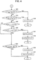
- the control device 50 repeats the processing shown in the flowcharts in FIGS. 3 and 4 at a predetermined time interval (e.g., an interval of several tens of milliseconds to several hundreds of milliseconds) during the operation of the internal combustion engine 10.
- the control device 50 calculates an accelerator pedal pressing amount (a required load), an engine speed NE, a crank angle, a temperature of the coolant, and the like based on the detection values detected by the accelerator pedal pressing amount detecting device 25, the rotation detecting device 22, the coolant temperature detecting device 28C, and the like and stores them in RAM in step S11, and the control device 50 then proceeds with step S12.
- step S12 the control device 50 retrieves a fuel injection flag from RAM and determines whether the fuel injection flag is ON, that is, the control device 50 determines whether the fuel injection amount and the fuel injection start timing of each of a first preliminary injection J1, a second preliminary injection J2, and a main injection JM1 (see FIG. 5 ) of this time have been set.
- the fuel injection flag is set to OFF and stored in RAM at the startup of the control device 50.
- the control device 50 determines that the fuel injection flag is ON (S12: YES)
- the control device 50 proceeds with step S22, which will be described later.
- step S13 the control device 50 obtains a fuel injection amount Q2 of each of the first preliminary injection J1 and the second preliminary injection J2 and a fuel injection amount Q3 of the main injection JM1 of this time based on the required load and the engine speed NE obtained in step S11 and stores them in RAM, and the control device 50 then proceeds with step S14.
- the fuel injection amount Q2 of each of the optimal first preliminary injection J1 and second preliminary injection J2 and the optimal fuel injection amount Q3 of the main injection JM1 for the required load and the engine speed NE are obtained by testing in advance, and the relationship between the required load and the engine speed NE and the fuel injection amounts Q2, Q3 is stored in a map. Accordingly, the control device 50 may refer to the map for calculation of the fuel injection amounts Q2, Q3.
- the fuel injection amounts Q2, Q3 may be corrected as necessary based on the detection value of the temperature of the coolant.
- step S14 the control device 50 obtains a fuel injection start timing of each of the first preliminary injection J1, the second preliminary injection J2, and the main injection JM1 based on the required load and the engine speed NE obtained in step S11 and stores them in RAM, and the control device 50 then proceeds with step S15.
- the fuel injection start timing of each of the optimal first preliminary injection J1, second preliminary injection J2, and main injection JM1 for the required load and the engine speed NE is obtained by testing in advance, and the relationship between the required load and the engine speed NE and the fuel injection start timings is stored in a map.
- the control device 50 may refer to the map for calculation of the fuel injection start timing of each of the first preliminary injection J1, the second preliminary injection J2, and the main injection JM1.
- the fuel injection start timing of each of the first preliminary injection J1, the second preliminary injection J2, and the main injection JM1 may be corrected based on the detection value of the temperature of the coolant.
- the fuel injection start timing of the main injection JM1 is set such that the fuel injection amount injected from the fuel injection openings 49 of the fuel injection valves 43A-43D becomes maximal at a compression top dead center TDC.
- the fuel injection start timings of the first preliminary injection J1 and the second preliminary injection J2 are set such that the combustion of the fuel injected by the first preliminary injection J1 and the second preliminary injection J2 before the main injection JM1 generates no heat or very little heat.
- the fuel injection start timing of a conventional main injection JM2 is set such that the fuel injection amount injected from the fuel injection openings 49 of the fuel injection valves 43A-43D becomes maximal at a position after the compression top dead center TDC. Accordingly, the fuel injection start timing of the main injection JM1 is earlier than that of the conventional main injection JM2 by time T1.
- the control device 50 retrieves the fuel injection flag from RAM, sets the flag to ON, and restores the flag in RAM in step S15, and the control device 50 then proceeds with step S16.
- step S16 the control device 50 retrieves the fuel injection amount Q2 of each of the first preliminary injection J1 and the second preliminary injection J2 and the fuel injection amount Q3 of the main injection JM1 of this time from RAM and stores the total fuel injection amount of the amounts Q2 and Q3 in RAM. Then, the control device 50 determines whether the total fuel injection amount is equal to or more than a predetermined fuel injection amount threshold Q1.
- the fuel injection amount threshold Q1 is stored in ROM or EEPROM of the storage device 53 in advance.
- control device 50 determines that the total fuel injection amount is less than the fuel injection amount threshold Q1 (S16: NO)
- the control device 50 proceeds with step S17.
- the control device 50 retrieves a water injection flag from RAM, sets the flag to OFF, and restores the flag in RAM in step S17, and the control device 50 proceeds with step S22, which will be described later.
- the water injection flag is set to OFF and stored in RAM at the startup of the control device 50.
- step S18 the control device 50 determines whether a condition of a water injection K1 executed by the auxiliary injection valves 63A-63D is satisfied. For example, the control device 50 determines that the condition of the water injection K1 executed by the auxiliary injection valves 63A-63D is not satisfied, while the engine is being warmed up because the temperature of the coolant is less than a predetermined temperature or when a required torque is equal to or less than a predetermined torque.
- control device 50 determines that the condition of the water injection K1 executed by the auxiliary injection valves 63A-63D is not satisfied (S18: NO)
- the control device 50 performs the processing in step S17.
- the control device 50 determines that the condition of the water injection K1 executed by the auxiliary injection valves 63A-63D is satisfied (S18: YES)
- the control device 50 proceeds with step S19.
- the control device 50 retrieves the total fuel injection amount calculated in step S16 from RAM, obtains a water injection amount Q5 of the water injection K1 of this time (see FIG. 5 ) based on the total fuel injection amount, and stores it in RAM in step S19, and the control device 50 then proceeds with step S20.
- the water injection amount Q5 of the optimal water injection K1 injected by the auxiliary injection valve valves 63A-63D for the total fuel injection amount injected by the fuel injection valves 43A-43D is obtained by testing in advance, and the relationship between the total fuel injection amount and the water injection amount Q5 is stored in a map M1.
- the control device 50 refers to the map M1 to calculate the water injection amount Q5.
- the temperature of the water 68 retained in the water tank 67 may be detected by a water temperature sensor to correct the water injection amount Q5.
- step S20 the control device 50 obtains a water injection start timing of the water injection amount Q5 of the water injection K1 of the auxiliary injection valves 63A-63D based on the fuel injection start timing of the main injection JM1 of the fuel F obtained in step S14 and stores it in RAM, and the control device 50 then proceeds with step S21.
- the optimal water injection K1 is executed after the second preliminary injection J2 and before the fuel injection start timing of the main injection JM1
- the water injection start timing of the water injection amount Q5 of the optimal water injection K1 is obtained by testing in advance, and the relationship between the fuel injection start timing of the main injection JM1 and the water injection start timing of the water injection amount Q5 of the water injection K1 is stored in a map.
- the control device 50 may refer to the map for calculation of the water injection start timing of the water injection amount Q5 of the water injection K1. Accordingly, water injection times T2-T3 are finished before the fuel injection start timing of the main injection JM1 (a crank angle at time T4).
- the control device 50 retrieves the water injection flag from RAM, sets the flag to ON, and restores the flag in RAM in step S21, and the control device 50 then proceeds with step S22.
- the water injection flag is set to OFF and stored in RAM at the startup of the control device 50.
- the control device 50 retrieves the crank angle obtained in step S11 and the fuel injection start timing of the first preliminary injection J1 obtained in step S14 from RAM, and determines whether the crank angle corresponds to the fuel injection start timing of the first preliminary injection J1 (see FIG. 5 ).
- step S23 the control device 50 controls the operation of the fuel injection valve (e.g., the fuel injection valve 43A) of this time so as to achieve the fuel injection amount Q2 of the first preliminary injection J1 obtained in step S13.
- the control device 50 ends the processing after injecting the fuel injection amount Q2 of the first preliminary injection J1 obtained in step S13.
- step S24 the control device 50 retrieves the crank angle obtained in step S11 and the fuel injection start timing of the second preliminary injection J2 obtained in step S14 from RAM, and determines whether the crank angle corresponds to the fuel injection start timing of the second preliminary injection J2 (see FIG. 5 ).
- step S23 the control device 50 controls the operation of the fuel injection valve (e.g., the fuel injection valve 43A) of this time so as to achieve the fuel injection amount Q2 of the second preliminary injection J2 obtained in step S13.
- the control device 50 ends the processing after injecting the fuel injection amount Q2 of the second preliminary injection J2 obtained in step S13.
- step S25 the control device 50 retrieves the water injection flag from RAM and determines whether the water injection flag is ON, that is, the control device 50 determines whether the water injection amount Q5 and the water injection start timing of the water injection K1 of this time have been set.
- step S29 the control device 50 proceeds with step S29, which will be described later.
- step S26 the control device 50 retrieves the crank angle obtained in step S11 and the water injection start timing of the water injection K1 obtained in step S20 from RAM, and determines whether the crank angle corresponds to the water injection start timing of the water injection K1 (the crank angle at time T2 in FIG. 5 ).
- step S27 the control device 50 controls the operation of the auxiliary injection valve (e.g., the auxiliary injection valve 63A) of this time so as to achieve the water injection amount Q5 of the water injection K1 obtained in step S19.
- the control device 50 controls so that the auxiliary injection valve 63A injects the water injection amount Q5 of the water 68 to the predetermined region FL (see FIGS. 7 and 8 ) around the plurality of fuel injection openings 49 of the fuel injection valve 43A (e.g., eight fuel injection openings, see FIGS. 7 and 8 ).
- the predetermined region FL (see FIGS. 7 and 8 ) around the plurality of fuel injection openings 49 of the fuel injection valve 43A (see FIGS. 7 and 8 ) is cooled by the heat of vaporization of the water 68 to a temperature below the ignition temperature of the fuel F.
- the control device 50 proceeds with step S28 after injecting the water injection amount Q5 of the water injection K1 obtained in step S19.
- the control device 50 retrieves the water injection flag from RAM, sets the flag to OFF, and restores the flag in RAM, and the control device 50 ends the processing.
- step S29 the control device 50 retrieves the crank angle obtained in step S11 and the fuel injection start timing of the main injection JM1 obtained in step S14 from RAM, and determines whether the crank angle corresponds to the fuel injection start timing of the main injection JM1 (the crank angle at time T4 in FIG. 5 ).
- the control device 50 ends the processing.
- step S30 the control device 50 controls the operation of the fuel injection valve (e.g., the fuel injection valve 43A) of this time so as to achieve the fuel injection amount Q3 of the main injection JM1 obtained in step S13.
- the control device 50 controls so that the fuel injection amount Q3 of the fuel F is injected from the plurality of fuel injection openings 49 of the fuel injection valve 43A (e.g., eight fuel injection openings, see FIGS. 7 and 8 ) to the peripheral portion of the cavity 76 formed in the piston 73.
- the fuel F injected from the fuel injection openings 49 of the fuel injection valve 43A is ignited after passing through the predetermined region FL cooled by the heat of vaporization of the water 68 injected from the auxiliary injection valve 63A to a temperature below the ignition temperature of the fuel F, so that mixing of the fuel F and air is promoted. That is, as illustrated in FIG. 5 , the main injection JM1 is injected earlier than the conventional main injection JM2 by time T1, and passes through the predetermined region FL without being ignited. Therefore, mixing of the injected fuel F and air is promoted more than before so as to help to reduce smoke.
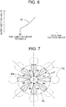
- the fuel F that has reached the outside of the predetermined region FL is ignited at ignition regions FA. That is, the predetermined region FL is located between the fuel injection openings 49 and the ignition regions FA where the fuel F of the main injection JM1 injected from the fuel injection valve 43A is ignited. Further, as illustrated in FIG. 5 , since the water 68 injected from the auxiliary injection valve 63A directly receives (recovers) heat from flame of the combustion to increase volume expansion by vaporization, the pressure in the cylinder is increased by a predetermined pressure ⁇ P than before at a position after a compression top dead center TDC to increase the output torque and therefore help the improvement of fuel economy.
- the fuel is surely ignited near the wall surface of the combustion chamber 75 without the possibility of an accidental fire even if the predetermined region FL around the fuel injection openings 49 (e.g., eight openings) is excessively cooled. Accordingly, the combustion robustness is increased compared to a case where the whole of the combustion chamber 75 is cooled.
- the consumption of the water 68 may be reduced since the water 68 is injected by the auxiliary injection valves 63A-63D only to the predetermined region FL around the fuel injection openings 49.
- step S30 the fuel injection amount Q3 of the main injection JM1 obtained in step S13 is injected in step S30, and the control device 50 then proceeds with step S31.
- step S31 the control device 50 retrieves the fuel injection flag from RAM, sets the flag to OFF, and restores the flag in RAM, and the control device 50 then ends the processing.
- the water 68 is retained in the water tank 67 (i.e., the liquid tank) located outside the internal combustion engine 10, and supplied by the water pump 66 from the water tank 67 to the auxiliary injection valves 63A-63D.
- This configuration reduces an increase in the temperature of the water 68 caused by increasing temperature of the internal combustion engine 10, thereby enhancing the cooling effect of the heat of vaporization of the water 68 in the predetermined region FL around the plurality of fuel injection openings 49 of each of the fuel injection valves 43A-43D.
- the present invention is not limited to the present embodiments, and the embodiments may be modified, added, or deleted in various manners without changing the gist of the present invention.
- the embodiments may be modified in following manners.
- the same reference numerals of the internal combustion engine 10 in the following description as those of the internal combustion engine 10 of the embodiments in FIGS. 1-8 indicate the same or equivalent parts as those of the internal combustion engine 10 of the embodiments in FIGS. 1-8 .
- cylindrical members 82 into which the fuel injection valves 43A-43D are fitted from above may be provided instead of the auxiliary injection valves 63A-63D, wherein each of the cylindrical members 82 is approximately cylindrically formed, made of a porous material, including an unglazed ceramic material, and fitted into a through hole 72A formed at the center of the upper wall surface of the combustion chamber 75 so that the bottom end of the cylindrical member 82 faces the combustion chamber 75. That is, the cylinder head 72 may have the through holes 72A in which the fuel injection valves 43A-43D are disposed facing the combustion chambers 75, respectively.
- each cylindrical member 82 is approximately equal to the thickness of the cylinder head 72, and the bottom end surface of the cylindrical member 82 is in plane with the upper wall surface of the combustion chamber 75.
- FIG. 9 illustrates the cylindrical member 82 into which the fuel injection valve 43A is fitted from above.
- each supply member 81 having an approximately box shape with a downward opening and a circular cross section are disposed on the cylinder head 72 so that each supply member 81 is coaxial with the corresponding cylindrical member 82 and covers the whole of the top end surface of the cylindrical member 82.
- the supply members 81 respectively have, at the centers of the ceiling portions thereof, through holes 81A into which the respective fuel injection valves 43A-43D are fitted from above.
- the supply members 81 are connected to respective water pipes 62A-62D.
- the fuel injection valves 43A-43D are fitted into from above and fixed to the through holes 81A of the supply members 81 and the cylindrical members 82, respectively.
- FIG. 9 illustrates the water pipe 62A.
- the water 68 is supplied to the top end surfaces of the cylindrical members 82 through the water pipes 62A-62D and the supply members 81, and seeps out from the bottom end surfaces of the cylindrical members 82. Accordingly, as illustrated in the left of FIG. 9 , the water 68 is supplied to the predetermined region FL around the fuel injection openings 49 (see FIG. 7 ) of each of the fuel injection valves 43A-43D and cools the predetermined region FL to a temperature below the ignition temperature of the fuel F by the heat of vaporization.
- the fuel F of the main injection JM1 injected from the fuel injection openings 49 of the fuel injection valve 43A is ignited after passing through the predetermined region FL cooled by the heat of vaporization of the water 68 to a temperature below the ignition temperature of the fuel F, so that mixing of the fuel F and air is promoted. That is, the fuel F of the main injection JM1 passes through the predetermined region FL without being ignited. Therefore, mixing of the injected fuel F and air is promoted more than before so as to help to reduce smoke.
- the fuel F that has reached the outside of the predetermined region FL is ignited at ignition regions FA (see FIGS. 7 and 8 ). That is, the predetermined region FL is located between the fuel injection openings 49 and the ignition regions FA where the fuel F of the main injection JM1 injected from the fuel injection valve 43A is ignited. Further, since the water 68 that seeps out from the bottom end surfaces of the cylindrical members 82 directly receives (recovers) heat from flame of the combustion to increase volume expansion by vaporization, the pressure in the cylinder is increased by a predetermined pressure ⁇ P (see FIG. 5 ) than before at a position after a compression top dead center TDC to increase the output torque and therefore help the improvement of fuel economy.
- a predetermined pressure ⁇ P see FIG. 5
- liquid injected to the predetermined region FL around the fuel injection openings 49 (e.g., eight openings) through the auxiliary injection valves 63A-63D is not limited to the water 68, for example, liquid, such as methanol, that is less flammable than the fuel F, such as light oil, may be injected to the predetermined region FL.
- liquid, such as methanol that is less flammable than the fuel F, such as light oil
- the heat of vaporization of the liquid, such as methanol cools the predetermined region FL to promote mixing of the fuel F and air, thereby helping to reduce smoke.
- the coolant may be partially supplied to the auxiliary injection valves 63A-63D by a water pump (not illustrated) of the internal combustion engine 10. This allows the coolant to be partially supplied to the auxiliary injection valves 63A-63D so that the auxiliary injection valves 63A-63D inject the coolant to the predetermined region FL only while the internal combustion engine 10 is driven.
Landscapes
- Engineering & Computer Science (AREA)
- Chemical & Material Sciences (AREA)
- Combustion & Propulsion (AREA)
- Mechanical Engineering (AREA)
- General Engineering & Computer Science (AREA)
- Electrical Control Of Air Or Fuel Supplied To Internal-Combustion Engine (AREA)
- Combined Controls Of Internal Combustion Engines (AREA)
- Output Control And Ontrol Of Special Type Engine (AREA)
- Fuel-Injection Apparatus (AREA)
Abstract
Description
- The present invention relates to an internal combustion engine.
- Various technologies have been designed to inject fuel into a combustion chamber of an internal combustion engine. For example, in a fuel injection valve with ducts described in
Patent Document 1, the fuel injection valve is mounted in a cylinder head of the internal combustion engine. The fuel injection valve is inserted into the cylinder head from above to directly inject high-pressure fuel, which is supplied from a common rail, into the combustion chamber. Each of the ducts is formed of a hollow tube and mounted immediately behind a fuel injection opening of the fuel injection valve. The injected fuel passes through the duct without being exposed to the high-temperature gas in a cylinder, so that time to ignition is extended to promote mixing of the fuel and air so as to reduce smoke. - Patent Document 1:
United States Patent Application Publication 2017/0114998 - However, in the fuel injection valve with ducts described in
Patent Document 1, the ducts each formed of a hollow tube should be aligned with the fuel injection openings of the fuel injection valve. This configuration complicates a duct structure and assembly work of the internal combustion engine, thereby increasing a manufacturing cost. - The present invention is devised in view of these points and to provide an internal combustion engine that has a simple configuration capable of extending time to ignition of fuel injected from a fuel injection valve so as to reduce smoke without decreasing combustion robustness and fuel economy.
- In order to solve the problem described above, the first invention of the present invention is an internal combustion engine that comprises a fuel injection valve configured to inject fuel in a combustion chamber of the internal combustion engine; and a cooling medium supply device configured to supply liquid that is less flammable than the fuel to the combustion chamber, wherein the cooling medium supply device is configured to supply the liquid to a predetermined region around a plurality of fuel injection openings of the fuel injection valve to decrease a temperature of the predetermined region before a main injection of the fuel by the fuel injection valve.
- Next, the second invention of the present invention is the internal combustion engine according to the first invention, wherein the predetermined region is located between the fuel injection openings and an ignition region where the fuel of a main injection injected from the fuel injection valve is ignited.
- Next, the third invention of the present invention is the internal combustion engine according to the first invention or the second invention, wherein the cooling medium supply device includes an auxiliary injection valve that is configured to inject the liquid to the predetermined region in the combustion chamber, the internal combustion engine includes an injection control device that is configured to control a fuel injection of the fuel injection valve and a liquid injection of the auxiliary injection valve, and the injection control device includes a fuel injection control part configured to control the fuel injection valve so that the fuel injection valve executes the main injection after executing a plurality of preliminary injections; and a cooling medium injection control part configured to control the auxiliary injection valve so that the auxiliary injection valve injects the liquid to the predetermined region after the plurality of preliminary injections and before the main injection.
- Next, the fourth invention of the present invention is the internal combustion engine according to the first invention or the second invention, wherein the internal combustion engine includes a cylinder head that has a through hole in which the fuel injection valve is disposed facing the combustion chamber, the cooling medium supply device includes: a cylindrical member into which the fuel injection valve is fitted from above, wherein the cylindrical member is cylindrically formed and made of a porous material including an unglazed ceramic material, and fitted into the through hole so that a bottom end of the cylindrical member faces the combustion chamber; and a supply member disposed on the cylinder head and configured to supply the liquid to a top end of the cylindrical member, and the liquid seeps out from the bottom end of the cylindrical member and is supplied to the predetermined region around the plurality of fuel injection openings to decrease the temperature of the predetermined region.
- Next, the fifth invention of the present invention is the internal combustion engine according to any one of the first to fourth inventions, wherein the internal combustion engine includes: a liquid tank disposed outside the internal combustion engine and in which the liquid is retained; and a liquid supply device configured to supply the liquid from the liquid tank to the cooling medium supply device.
- Next, the sixth invention of the present invention is the internal combustion engine according to any one of the first to fifth inventions, wherein the liquid is non-combustible liquid comprising water.
- According to the first invention, the cooling medium supply device supplies the liquid, which is less flammable than the fuel, to the predetermined region around the plurality of fuel injection openings of the fuel injection valve to decrease the temperature of the predetermined region by evaporative latent heat of the liquid before the main injection of the fuel by the fuel injection valve. This allows time to ignition of the fuel in the predetermined region to be extended to promote mixing of the injected fuel and air so as to reduce smoke since the temperature of the predetermined region around the plurality of fuel injection openings of the fuel injection valve has been decreased when the fuel injection valve executes the main injection of the fuel.
- In addition, the predetermined region whose temperature is decreased by evaporative latent heat of the liquid is a region around the plurality of fuel injection openings of the fuel injection valve, so that even if the predetermined region is excessively cooled, high temperature gas exists near the wall surface of the combustion chamber, which prevents an accidental fire and reduces a decrease in the combustion robustness and the fuel economy. In addition, the consumption of the liquid may be reduced since the liquid only needs to be supplied to the predetermined region around the plurality of fuel injection openings of the fuel injection valve.
- According to the second invention, the predetermined region around the plurality of fuel injection openings of the fuel injection valve is located between the fuel injection openings and the ignition region where the fuel of the main injection injected from the fuel injection valve is ignited. This allows the injected fuel and air to be effectively mixed so as to further reduce smoke in the predetermined region when the fuel injection valve executes the main injection of the fuel.
- According to the third invention, the auxiliary injection valve configured to inject the liquid to the predetermined region around the plurality of fuel injection openings is provided in the combustion chamber, and the injection control device controls the auxiliary injection valve so that the auxiliary injection valve injects the liquid to the predetermined region after the plurality of preliminary injections by the fuel injection valve and before the main injection by the fuel injection valve. This ensures that the temperature of the predetermined region around the plurality of fuel injection openings of the fuel injection valve has been decreased when the fuel injection valve executes the main injection of the fuel. As a result, time to ignition of the fuel in the predetermined region is extended to promote mixing of the injected fuel and air when the fuel injection valve executes the main injection of the fuel, so that smoke is reduced by this simple configuration with the auxiliary injection valve.
- According to the fourth invention, the cylindrical member cylindrically formed, made of a porous material including an unglazed ceramic material, and into which the fuel injection valve is fitted is disposed on the cylinder head, and the supply member supplies the liquid to the top end of the cylindrical member. The liquid that seeps out from the bottom end of the cylindrical member is supplied to the predetermined region around the plurality of fuel injection openings of the fuel injection valve, and the temperature of the predetermined region is decreased by the heat of vaporization of the liquid. This ensures that the temperature of the predetermined region around the plurality of fuel injection openings of the fuel injection valve has been decreased when the fuel injection valve executes the main injection of the fuel. As a result, time to ignition of the fuel in the predetermined region is extended to promote mixing of the injected fuel and air when the fuel injection valve executes the main injection of the fuel, so that smoke is reduced by this simple configuration of the cylindrical member into which the fuel injection valve is inserted.
- According to the fifth invention, the liquid is retained in the liquid tank located outside the internal combustion engine, and supplied to the cooling medium supply device by the liquid supply device. This allows an increase in the temperature of the liquid caused by increasing temperature of the internal combustion engine to be reduced, thereby enhancing the cooling effect of the heat of vaporization of the liquid in the predetermined region around the plurality of fuel injection openings of the fuel injection valve.
- According to the sixth invention, since the liquid is non-combustible liquid including water, the liquid directly receives (recovers) heat from the gas in the combustion chamber to cool the predetermined region, and then directly receives (recovers) heat from flame of the combustion chamber to increase volume expansion by vaporization, and therefore helps the improvement of fuel economy.
-
-
FIG. 1 is a schematic view explaining a configuration of an internal combustion engine according to a present embodiment. -
FIG. 2 is a sectional view illustrating an exemplary operation of a fuel injection valve and an auxiliary injection valve. -
FIG. 3 is a first flowchart showing a water injection control process performed by a control device. -
FIG. 4 is a second flowchart showing the water injection control process performed by the control device. -
FIG. 5 is a view showing exemplary variations of a pressure in a cylinder, a fuel injection amount, and a water injection amount relative to a crank angle. -
FIG. 6 is a view showing an exemplary water injection amount setting map for deciding the water injection amount relative to the fuel injection amount. -
FIG. 7 is a plane view illustrating an exemplary main injection of fuel executed by the fuel injection valve. -
FIG. 8 is a side view illustrating the exemplary main injection of fuel executed by the fuel injection valve. -
FIG. 9 is a sectional view illustrating an exemplary operation of the fuel injection valve and a cylindrical member according to anotherembodiment 1. - An embodiment of an internal combustion engine according to the present invention is explained in detail with reference to the accompanying drawings. Firstly, a schematic configuration of an
internal combustion engine 10 according to the present embodiment will be described with reference toFIG. 1 . In the explanation of this embodiment, a diesel engine system mounted on a vehicle will be described as an example of theinternal combustion engine 10. - The
internal combustion engine 10 according to the present embodiment will be described in order from the intake side to the exhaust side. As illustrated inFIG. 1 , an intake flow rate detecting device 21 (e.g., an intake flow rate sensor) is disposed at an inlet of anintake pipe 11A. The intake flowrate detecting device 21 outputs a detection signal, which corresponds to the flow rate of air drawn into theinternal combustion engine 10, to a control device 50 (i.e., an injection control device, a fuel injection control part, and a cooling medium injection control part) of theinternal combustion engine 10. The intake flowrate detecting device 21 includes an intake airtemperature detecting device 28A (e.g., an intake air temperature sensor). The intake airtemperature detecting device 28A outputs a detection signal, which corresponds to the temperature of the intake air passing through the intake flowrate detecting device 21, to thecontrol device 50. - An outlet of the
intake pipe 11A is connected to an inlet of acompressor 35, and an outlet of thecompressor 35 is connected to an inlet of anintake pipe 11B. Aturbocharger 30 includes thecompressor 35 that includes acompressor impeller 35A and aturbine 36 that includes a turbine impeller 36A. Thecompressor impeller 35A is rotationally driven by the turbine impeller 36A that is rotationally driven by the exhaust gas, and supercharges the exhaust gas by pumping the intake air from theintake pipe 11A to theintake pipe 11B. - The
intake pipe 11A disposed upstream of thecompressor 35 is provided with a compressor upstreampressure detecting device 24A. The compressor upstreampressure detecting device 24A is, for example, a pressure sensor, and outputs a detection signal, which corresponds to the pressure of the intake air in theintake pipe 11A disposed upstream of thecompressor 35, to thecontrol device 50. Theintake pipe 11B disposed downstream of thecompressor 35 is provided with a compressor downstreampressure detecting device 24B (disposed in theintake pipe 11B and between thecompressor 35 and an intercooler 16). The compressor downstreampressure detecting device 24B is, for example, a pressure sensor, and outputs a detection signal, which corresponds to the pressure in theintake pipe 11B disposed downstream of thecompressor 35, to thecontrol device 50. - The
intake pipe 11B is provided with theintercooler 16 on the upstream side thereof, and athrottle device 47 disposed downstream of theintercooler 16. Theintercooler 16 is disposed downstream of the compressor downstreampressure detecting device 24B to lower the temperature of the intake air supercharged by thecompressor 35. An intake airtemperature detecting device 28B (e.g., an intake air temperature sensor) is disposed between theintercooler 16 and thethrottle device 47. The intake airtemperature detecting device 28B outputs a detection signal, which corresponds to the intake air temperature lowered by theintercooler 16, to thecontrol device 50. - The
throttle device 47 adjusts the intake flow rate by driving athrottle valve 47A that adjusts the opening degree of theintake pipe 11B based on a control signal from thecontrol device 50. Thecontrol device 50 is capable of adjusting the position of thethrottle valve 47A disposed on theintake pipe 11B by outputting a control signal to thethrottle device 47 based on the detection signal from a throttle position detecting device 47S (e.g., a throttle position sensor) and a target throttle position. Thecontrol device 50 determines the target throttle position based on the pressing amount of the accelerator pedal detected by a detection signal from an accelerator pedal pressingamount detecting device 25 and the operation condition of theinternal combustion engine 10. - The accelerator pedal pressing
amount detecting device 25 is, for example, an accelerator pedal pressing angle sensor, and is provided on the accelerator pedal. Thecontrol device 50 is capable of detecting the pressing amount of the accelerator pedal pressed by the driver by the detection signal from the accelerator pedal pressingamount detecting device 25. - An outlet of an
EGR pipe 13 is connected to a pressure detecting device 24C that is disposed downstream of thethrottle device 47 in theintake pipe 11B. The outlet of theintake pipe 11B is connected to an inlet of an intake manifold 11C, and an outlet of the intake manifold 11C is connected to an inlet of theinternal combustion engine 10. The pressure detecting device 24C is, for example, a pressure sensor, and outputs a detection signal, which corresponds to the pressure of the intake air just before flowing into the intake manifold 11C, to thecontrol device 50. EGR gas flows into an inlet of the EGR pipe 13 (a connecting portion between anexhaust pipe 12B and the EGR pipe 13), and is discharged from the outlet of the EGR pipe 13 (a connecting portion between theintake pipe 11B and the EGR pipe 13) into theintake pipe 11B. TheEGR pipe 13 forms a path through which the EGR gas flows, and the path serves as an EGR path. - The
internal combustion engine 10 has a plurality ofcylinders 45A-45D provided with a plurality offuel injection valves 43A-43D, respectively. Thefuel injection valves 43A-43D are supplied with fuel through acommon rail 41 andfuel lines 42A-42D, and thefuel injection valves 43A-43D are driven by a control signal from thecontrol device 50 to inject fuel into therespective cylinders 45A-45D. - The
cylinders 45A-45D are provided withauxiliary injection valves 63A-63D (i.e., cooling medium supply devices), respectively. Theauxiliary injection valves 63A-63D are supplied with water (i.e., non-combustible liquid) through a water-supplycommon rail 61 andwater lines 62A-62D, and theauxiliary injection valves 63A-63D are driven by a control signal from thecontrol device 50 to inject water into therespective cylinders 45A-45D. - The water-supply
common rail 61 is coupled, via asupply pipe 65 and a water pump 66 (i.e., a liquid supply device) to a water tank 67 (i.e., a liquid tank) that is located away from theinternal combustion engine 10. Thewater pump 66 is an electric pump rotationally driven by a drive signal from thecontrol device 50, and is rotatable in both of forward and reverse directions. Water 68 (i.e., non-combustible liquid) in thewater tank 67 is drawn by a forward rotation of thewater pump 66 and supplied to the water-supplycommon rail 61 through thesupply pipe 65. Thewater 68 in the water-supplycommon rail 61 and thesupply pipe 65 is drawn by a reverse rotation of thewater pump 66, and returned to thewater tank 67. Thesupply pipe 65 may be provided with a water pressure sensor for detecting a pressure of thewater 68 in thesupply pipe 65. - The
water tank 67 accommodates a level gauge 69 (i.e., a level detector) for detecting a remaining amount (a water level) of thewater 68 retained in thewater tank 67. Thewater 68 is drawn from thewater tank 67 filled up with thewater 68, and the level gauge (level detector) 69 outputs a signal (e.g., a signal corresponding tolevel 10 to level 1), which corresponds to a remaining amount of thewater 68 in thewater tank 67, to the control device (ECU) 50. - The
internal combustion engine 10 is provided with arotation detecting device 22, a coolanttemperature detecting device 28C, and the like. Therotation detecting device 22 is, for example, a rotation sensor, and outputs a detection signal, which corresponds to a rotation angle of the crankshaft of the internal combustion engine 10 (i.e., a crank angle), to thecontrol device 50. For example, therotation detecting device 22 produces an output pulse every time the crank shaft rotates 15 degrees, and the output pulse is input to thecontrol device 50. Thecontrol device 50 calculates a crank angle and an engine speed from the output pulse from therotation detecting device 22. The coolanttemperature detecting device 28C is, for example, a temperature sensor, and detects the temperature of the coolant circulated in theinternal combustion engine 10 and outputs a detection signal corresponding to the detected temperature to thecontrol device 50. - The
internal combustion engine 10 is connected on the exhaust side thereof to an inlet of anexhaust manifold 12A, and an outlet of theexhaust manifold 12A is connected to an inlet of theexhaust pipe 12B. An outlet of theexhaust pipe 12B is connected to an inlet of theturbine 36, and an outlet of theturbine 36 is connected to an inlet of an exhaust pipe 12C. - The
exhaust pipe 12B is connected to the inlet of theEGR pipe 13. Theexhaust pipe 12B is in communication with theintake pipe 11B through theEGR pipe 13 so that part of the exhaust gas in theexhaust pipe 12B (corresponding to an exhaust path) may be recirculated to theintake pipe 11B (corresponding to an intake path). Further, theEGR pipe 13 is provided with apath switching device 14A, abypass pipe 13B, anEGR cooler 15, and anEGR valve 14B. - The EGR gas flows from the
exhaust pipe 12B into theEGR pipe 13, and thepath switching device 14A serves as a path switching valve that switches a path, in response to a control signal from thecontrol device 50, between an EGR cooler path that allows the EGR gas to be returned to the intake path through theEGR cooler 15 and a bypass path that allows the EGR gas to be returned to theintake pipe 11B through thebypass pipe 13B without passing through theEGR cooler 15. Thebypass pipe 13B bypasses theEGR cooler 15, an inlet of thebypass pipe 13B is connected to thepath switching device 14A, and an outlet of thebypass pipe 13B is connected to theEGR pipe 13 at a position between theEGR valve 14B and theEGR cooler 15. - The
EGR valve 14B (EGR valve) is disposed downstream of theEGR cooler 15 in theEGR pipe 13 and downstream of the junction of theEGR pipe 13 and thebypass pipe 13B. TheEGR valve 14B adjusts the opening degree of theEGR pipe 13 based on a control signal from thecontrol device 50 to adjust the flow rate of the EGR gas flowing through theEGR pipe 13. - Further, the
EGR cooler 15 is disposed in theEGR pipe 13 at a position between the junction of theEGR pipe 13 and thebypass pipe 13B and thepath switching device 14A. TheEGR cooler 15, i.e., a heat exchanger, is supplied with coolant, and theEGR cooler 15 cools and discharges the EGR gas flowed therein. - The
exhaust pipe 12B is provided with an exhaust gastemperature detecting device 29. The exhaust gastemperature detecting device 29 is, for example, an exhaust gas temperature sensor, and outputs a detection signal, which corresponds to the exhaust gas temperature, to thecontrol device 50. Based on the exhaust gas temperature detected by the exhaust gastemperature detecting device 29, the control state of theEGR valve 14B, and the operating state of theinternal combustion engine 10, thecontrol device 50 may estimate the temperature of the EGR gas flowed into theintake pipe 11B through theEGR pipe 13, the EGR cooler 15 (or thebypass pipe 13B), and theEGR valve 14B. - The outlet of the
exhaust pipe 12B is connected to the inlet of theturbine 36, and the outlet of theturbine 36 is connected to the inlet of the exhaust pipe 12C. Theturbine 36 is provided with avariable nozzle 33 that is capable of controlling the flow speed of the exhaust gas flowing to the turbine impeller 36A, and the opening degree of thevariable nozzle 33 is adjusted by anozzle driving device 31. Thecontrol device 50 adjusts the opening degree of thevariable nozzle 33 by outputting a control signal to thenozzle driving device 31 based on the detection signal from a nozzle opening degree detecting device 32 (e.g., a nozzle opening degree sensor) and a target nozzle opening degree. - The
exhaust pipe 12B disposed upstream of theturbine 36 is also provided with a turbine upstreampressure detecting device 26A. The turbine upstreampressure detecting device 26A is, for example, a pressure sensor, and outputs a detection signal, which corresponds to the pressure in theexhaust pipe 12B disposed upstream of theturbine 36, to thecontrol device 50. The exhaust pipe 12C disposed downstream of theturbine 36 is provided with a turbine downstreampressure detecting device 26B. The turbine downstreampressure detecting device 26B is, for example, a pressure sensor, and outputs a detection signal, which corresponds to the pressure in the exhaust pipe 12C disposed downstream of theturbine 36, to thecontrol device 50. - The outlet of the exhaust pipe 12C is connected to an exhaust gas purification device, which is not illustrated. For example, when a diesel engine serves as the
internal combustion engine 10, the exhaust gas purification device includes an oxidation catalyst, a particulate filter, a selective catalytic reduction, or the like. - The
control device 50, i.e., Electronic Control Unit (ECU), at least includes a processer 51 (i.e., CPU, Micro-Processing Unit (MPU) or the like), and a storage device 53 (i.e., DRAM, ROM, EEPROM, SRAM, HDD or the like). The control device 50 (i.e., ECU) detects the operation condition of theinternal combustion engine 10 based on the detection signals from various detection devices, which are not limited to but include the detecting devices described above, and controls various actuators, which are not limited to but include thefuel injection valves 43A-43D, theauxiliary injection valves 63A-63D, theEGR valve 14B, thepath switching device 14A, thenozzle driving device 31, and thethrottle device 47 described above. Thestorage device 53 stores programs and parameters for performing various processing, for example. - The
control device 50 is provided with an atmosphericpressure detecting device 23 that is, for example, an atmospheric pressure sensor. The atmosphericpressure detecting device 23 outputs a detection signal, which corresponds to the atmospheric pressure around thecontrol device 50, to thecontrol device 50. A vehiclespeed detecting device 27 is, for example, a vehicle speed detection sensor, and provided on the wheels or the like of the vehicle. The vehiclespeed detecting device 27 outputs a detection signal, which corresponds to the rotation speed of the wheels of the vehicle, to thecontrol device 50. - Next, the following will describe the mounting structures of the
fuel injection valves 43A-43D and theauxiliary injection valves 63A-63D with reference toFIG. 2 . Since thefuel injection valves 43A-43D and theauxiliary injection valves 63A-63D have approximately the same mounting structure, the following explanation will focus on the mounting structures of thefuel injection valve 43A and theauxiliary injection valve 63A. - As illustrated in
FIG. 2 , theinternal combustion engine 10 includes acylinder head 72 and acylinder block 71 in which acylinder 45A is formed. Thecylinder 45A has therein apiston 73 that reciprocates in thecylinder 45A. In thecylinder 45A, acombustion chamber 75 is formed between thepiston 73 and thecylinder head 72 to burn a fuel-air-mixture therein. The top of thepiston 73 has acavity 76 that has a depression shape. - The
fuel injection valve 43A is disposed at the center of an upper wall surface of thecombustion chamber 75 and configured to directly inject fuel F to the peripheral portion of thecavity 76 formed in the piston 73 (see the right ofFIG. 2 ). Theauxiliary injection valve 63A is disposed at the peripheral portion of the upper wall surface of thecombustion chamber 75 at an angle with respect to thefuel injection valve 43A, and configured to inject (supply) thewater 68, which is less flammable than the fuel F, to a predetermined region FL around a plurality of fuel injection openings 49 (e.g., eight fuel injection openings, seeFIGS. 7 and8 ) of thefuel injection valve 43A (see the left ofFIG. 2 ). The predetermined region FL around the plurality offuel injection openings 49 of thefuel injection valve 43A (seeFIGS. 7 and8 ) is cooled by the heat of vaporization of thewater 68 to a temperature below the ignition temperature of the fuel F. - Next, with reference to
FIGS. 3-8 , the following will describe an exemplary water injection control processing performed by thecontrol device 50 of theinternal combustion engine 10 for injecting thewater 68 with theauxiliary injection valves 63A-63D (seeFIG. 2 ) before the main injections of the fuel F by thefuel injection valves 43A-43D. Thecontrol device 50 repeats the processing shown in the flowcharts inFIGS. 3 and4 at a predetermined time interval (e.g., an interval of several tens of milliseconds to several hundreds of milliseconds) during the operation of theinternal combustion engine 10. - As illustrated in
FIGS. 3 and4 , firstly thecontrol device 50 calculates an accelerator pedal pressing amount (a required load), an engine speed NE, a crank angle, a temperature of the coolant, and the like based on the detection values detected by the accelerator pedal pressingamount detecting device 25, therotation detecting device 22, the coolanttemperature detecting device 28C, and the like and stores them in RAM in step S11, and thecontrol device 50 then proceeds with step S12. - In step S12, the
control device 50 retrieves a fuel injection flag from RAM and determines whether the fuel injection flag is ON, that is, thecontrol device 50 determines whether the fuel injection amount and the fuel injection start timing of each of a first preliminary injection J1, a second preliminary injection J2, and a main injection JM1 (seeFIG. 5 ) of this time have been set. The fuel injection flag is set to OFF and stored in RAM at the startup of thecontrol device 50. When thecontrol device 50 determines that the fuel injection flag is ON (S12: YES), thecontrol device 50 proceeds with step S22, which will be described later. - When the
control device 50 determines that the fuel injection flag is OFF (S12: NO), thecontrol device 50 proceeds with step S13. In step S13, thecontrol device 50 obtains a fuel injection amount Q2 of each of the first preliminary injection J1 and the second preliminary injection J2 and a fuel injection amount Q3 of the main injection JM1 of this time based on the required load and the engine speed NE obtained in step S11 and stores them in RAM, and thecontrol device 50 then proceeds with step S14. - For example, the fuel injection amount Q2 of each of the optimal first preliminary injection J1 and second preliminary injection J2 and the optimal fuel injection amount Q3 of the main injection JM1 for the required load and the engine speed NE are obtained by testing in advance, and the relationship between the required load and the engine speed NE and the fuel injection amounts Q2, Q3 is stored in a map. Accordingly, the
control device 50 may refer to the map for calculation of the fuel injection amounts Q2, Q3. The fuel injection amounts Q2, Q3 may be corrected as necessary based on the detection value of the temperature of the coolant. - In step S14, the
control device 50 obtains a fuel injection start timing of each of the first preliminary injection J1, the second preliminary injection J2, and the main injection JM1 based on the required load and the engine speed NE obtained in step S11 and stores them in RAM, and thecontrol device 50 then proceeds with step S15. - For example, the fuel injection start timing of each of the optimal first preliminary injection J1, second preliminary injection J2, and main injection JM1 for the required load and the engine speed NE is obtained by testing in advance, and the relationship between the required load and the engine speed NE and the fuel injection start timings is stored in a map. The
control device 50 may refer to the map for calculation of the fuel injection start timing of each of the first preliminary injection J1, the second preliminary injection J2, and the main injection JM1. The fuel injection start timing of each of the first preliminary injection J1, the second preliminary injection J2, and the main injection JM1 may be corrected based on the detection value of the temperature of the coolant. - For example, as illustrated in
FIG. 5 , the fuel injection start timing of the main injection JM1 is set such that the fuel injection amount injected from thefuel injection openings 49 of thefuel injection valves 43A-43D becomes maximal at a compression top dead center TDC. The fuel injection start timings of the first preliminary injection J1 and the second preliminary injection J2 are set such that the combustion of the fuel injected by the first preliminary injection J1 and the second preliminary injection J2 before the main injection JM1 generates no heat or very little heat. - In contrast, the fuel injection start timing of a conventional main injection JM2 is set such that the fuel injection amount injected from the
fuel injection openings 49 of thefuel injection valves 43A-43D becomes maximal at a position after the compression top dead center TDC. Accordingly, the fuel injection start timing of the main injection JM1 is earlier than that of the conventional main injection JM2 by time T1. - The
control device 50 retrieves the fuel injection flag from RAM, sets the flag to ON, and restores the flag in RAM in step S15, and thecontrol device 50 then proceeds with step S16. In step S16, thecontrol device 50 retrieves the fuel injection amount Q2 of each of the first preliminary injection J1 and the second preliminary injection J2 and the fuel injection amount Q3 of the main injection JM1 of this time from RAM and stores the total fuel injection amount of the amounts Q2 and Q3 in RAM. Then, thecontrol device 50 determines whether the total fuel injection amount is equal to or more than a predetermined fuel injection amount threshold Q1. The fuel injection amount threshold Q1 is stored in ROM or EEPROM of thestorage device 53 in advance. - When the
control device 50 determines that the total fuel injection amount is less than the fuel injection amount threshold Q1 (S16: NO), thecontrol device 50 proceeds with step S17. Thecontrol device 50 retrieves a water injection flag from RAM, sets the flag to OFF, and restores the flag in RAM in step S17, and thecontrol device 50 proceeds with step S22, which will be described later. The water injection flag is set to OFF and stored in RAM at the startup of thecontrol device 50. - When the
control device 50 determines that the total fuel injection amount is equal to or more than the fuel injection amount threshold Q1 (S16: YES), thecontrol device 50 proceeds with step S18. In step S18, thecontrol device 50 determines whether a condition of a water injection K1 executed by theauxiliary injection valves 63A-63D is satisfied. For example, thecontrol device 50 determines that the condition of the water injection K1 executed by theauxiliary injection valves 63A-63D is not satisfied, while the engine is being warmed up because the temperature of the coolant is less than a predetermined temperature or when a required torque is equal to or less than a predetermined torque. - When the
control device 50 determines that the condition of the water injection K1 executed by theauxiliary injection valves 63A-63D is not satisfied (S18: NO), thecontrol device 50 performs the processing in step S17. On the other hand, when thecontrol device 50 determines that the condition of the water injection K1 executed by theauxiliary injection valves 63A-63D is satisfied (S18: YES), thecontrol device 50 proceeds with step S19. Thecontrol device 50 retrieves the total fuel injection amount calculated in step S16 from RAM, obtains a water injection amount Q5 of the water injection K1 of this time (seeFIG. 5 ) based on the total fuel injection amount, and stores it in RAM in step S19, and thecontrol device 50 then proceeds with step S20. - For example, as illustrated in
FIG. 6 , the water injection amount Q5 of the optimal water injection K1 injected by the auxiliaryinjection valve valves 63A-63D for the total fuel injection amount injected by thefuel injection valves 43A-43D is obtained by testing in advance, and the relationship between the total fuel injection amount and the water injection amount Q5 is stored in a map M1. Thecontrol device 50 refers to the map M1 to calculate the water injection amount Q5. In addition, the temperature of thewater 68 retained in thewater tank 67 may be detected by a water temperature sensor to correct the water injection amount Q5. - In step S20, the
control device 50 obtains a water injection start timing of the water injection amount Q5 of the water injection K1 of theauxiliary injection valves 63A-63D based on the fuel injection start timing of the main injection JM1 of the fuel F obtained in step S14 and stores it in RAM, and thecontrol device 50 then proceeds with step S21. - As illustrated in
FIG. 5 , for example, since the optimal water injection K1 is executed after the second preliminary injection J2 and before the fuel injection start timing of the main injection JM1, the water injection start timing of the water injection amount Q5 of the optimal water injection K1 is obtained by testing in advance, and the relationship between the fuel injection start timing of the main injection JM1 and the water injection start timing of the water injection amount Q5 of the water injection K1 is stored in a map. Thecontrol device 50 may refer to the map for calculation of the water injection start timing of the water injection amount Q5 of the water injection K1. Accordingly, water injection times T2-T3 are finished before the fuel injection start timing of the main injection JM1 (a crank angle at time T4). - The
control device 50 retrieves the water injection flag from RAM, sets the flag to ON, and restores the flag in RAM in step S21, and thecontrol device 50 then proceeds with step S22. The water injection flag is set to OFF and stored in RAM at the startup of thecontrol device 50. Next, in step S22, thecontrol device 50 retrieves the crank angle obtained in step S11 and the fuel injection start timing of the first preliminary injection J1 obtained in step S14 from RAM, and determines whether the crank angle corresponds to the fuel injection start timing of the first preliminary injection J1 (seeFIG. 5 ). - When the
control device 50 determines that the crank angle corresponds to the fuel injection start timing of the first preliminary injection J1 (S22: YES), thecontrol device 50 proceeds with step S23. In step S23, as illustrated inFIG. 5 , thecontrol device 50 controls the operation of the fuel injection valve (e.g., thefuel injection valve 43A) of this time so as to achieve the fuel injection amount Q2 of the first preliminary injection J1 obtained in step S13. Thecontrol device 50 ends the processing after injecting the fuel injection amount Q2 of the first preliminary injection J1 obtained in step S13. - When the
control device 50 determines that the crank angle does not correspond to the fuel injection start timing of the first preliminary injection J1 (S22: NO), thecontrol device 50 proceeds with step S24. In step S24, thecontrol device 50 retrieves the crank angle obtained in step S11 and the fuel injection start timing of the second preliminary injection J2 obtained in step S14 from RAM, and determines whether the crank angle corresponds to the fuel injection start timing of the second preliminary injection J2 (seeFIG. 5 ). - When the
control device 50 determines that the crank angle corresponds to the fuel injection start timing of the second preliminary injection J2 (S24: YES), thecontrol device 50 proceeds with step S23. In step S23, as illustrated inFIG. 5 , thecontrol device 50 controls the operation of the fuel injection valve (e.g., thefuel injection valve 43A) of this time so as to achieve the fuel injection amount Q2 of the second preliminary injection J2 obtained in step S13. Thecontrol device 50 ends the processing after injecting the fuel injection amount Q2 of the second preliminary injection J2 obtained in step S13. - When the
control device 50 determines that the crank angle does not correspond to the fuel injection start timing of the second preliminary injection J2 (S24: NO), thecontrol device 50 proceeds with step S25. In step S25, thecontrol device 50 retrieves the water injection flag from RAM and determines whether the water injection flag is ON, that is, thecontrol device 50 determines whether the water injection amount Q5 and the water injection start timing of the water injection K1 of this time have been set. When thecontrol device 50 determines that the water injection flag is OFF (S25: NO), thecontrol device 50 proceeds with step S29, which will be described later. - When the
control device 50 determines that the water injection flag is ON (S25: YES), thecontrol device 50 proceeds with step S26. In step S26, thecontrol device 50 retrieves the crank angle obtained in step S11 and the water injection start timing of the water injection K1 obtained in step S20 from RAM, and determines whether the crank angle corresponds to the water injection start timing of the water injection K1 (the crank angle at time T2 inFIG. 5 ). - When the
control device 50 determines that the crank angle corresponds to the water injection start timing of the water injection K1 (S26: YES), thecontrol device 50 proceeds with step S27. In step S27, as illustrated inFIG. 5 , thecontrol device 50 controls the operation of the auxiliary injection valve (e.g., theauxiliary injection valve 63A) of this time so as to achieve the water injection amount Q5 of the water injection K1 obtained in step S19. Specifically, as illustrated in the left ofFIG. 2 , thecontrol device 50 controls so that theauxiliary injection valve 63A injects the water injection amount Q5 of thewater 68 to the predetermined region FL (seeFIGS. 7 and8 ) around the plurality offuel injection openings 49 of thefuel injection valve 43A (e.g., eight fuel injection openings, seeFIGS. 7 and8 ). - The predetermined region FL (see
FIGS. 7 and8 ) around the plurality offuel injection openings 49 of thefuel injection valve 43A (seeFIGS. 7 and8 ) is cooled by the heat of vaporization of thewater 68 to a temperature below the ignition temperature of the fuel F. Thecontrol device 50 proceeds with step S28 after injecting the water injection amount Q5 of the water injection K1 obtained in step S19. In step S28, thecontrol device 50 retrieves the water injection flag from RAM, sets the flag to OFF, and restores the flag in RAM, and thecontrol device 50 ends the processing. - When the
control device 50 determines that the crank angle does not correspond to the water injection start timing of the water injection K1 (S26: NO), thecontrol device 50 proceeds with step S29. In step S29, thecontrol device 50 retrieves the crank angle obtained in step S11 and the fuel injection start timing of the main injection JM1 obtained in step S14 from RAM, and determines whether the crank angle corresponds to the fuel injection start timing of the main injection JM1 (the crank angle at time T4 inFIG. 5 ). When thecontrol device 50 determines that the crank angle does not correspond to the fuel injection start timing of the main injection JM1 (S29: NO), thecontrol device 50 ends the processing. - When the
control device 50 determines that the crank angle corresponds to the fuel injection start timing of the main injection JM1 (S29: YES), thecontrol device 50 proceeds with step S30. In step S30, as illustrated inFIG. 5 , thecontrol device 50 controls the operation of the fuel injection valve (e.g., thefuel injection valve 43A) of this time so as to achieve the fuel injection amount Q3 of the main injection JM1 obtained in step S13. Specifically, as illustrated in the right ofFIG. 2 , thecontrol device 50 controls so that the fuel injection amount Q3 of the fuel F is injected from the plurality offuel injection openings 49 of thefuel injection valve 43A (e.g., eight fuel injection openings, seeFIGS. 7 and8 ) to the peripheral portion of thecavity 76 formed in thepiston 73. - Accordingly, as illustrated in
FIGS. 7 and8 , the fuel F injected from thefuel injection openings 49 of thefuel injection valve 43A is ignited after passing through the predetermined region FL cooled by the heat of vaporization of thewater 68 injected from theauxiliary injection valve 63A to a temperature below the ignition temperature of the fuel F, so that mixing of the fuel F and air is promoted. That is, as illustrated inFIG. 5 , the main injection JM1 is injected earlier than the conventional main injection JM2 by time T1, and passes through the predetermined region FL without being ignited. Therefore, mixing of the injected fuel F and air is promoted more than before so as to help to reduce smoke. - The fuel F that has reached the outside of the predetermined region FL is ignited at ignition regions FA. That is, the predetermined region FL is located between the
fuel injection openings 49 and the ignition regions FA where the fuel F of the main injection JM1 injected from thefuel injection valve 43A is ignited. Further, as illustrated inFIG. 5 , since thewater 68 injected from theauxiliary injection valve 63A directly receives (recovers) heat from flame of the combustion to increase volume expansion by vaporization, the pressure in the cylinder is increased by a predetermined pressure ΔP than before at a position after a compression top dead center TDC to increase the output torque and therefore help the improvement of fuel economy. - On the other hand, since air near the wall surface of the combustion chamber 75 (see
FIG. 2 ) is at a high temperature (e.g., approximately 600°C or more), the fuel is surely ignited near the wall surface of thecombustion chamber 75 without the possibility of an accidental fire even if the predetermined region FL around the fuel injection openings 49 (e.g., eight openings) is excessively cooled. Accordingly, the combustion robustness is increased compared to a case where the whole of thecombustion chamber 75 is cooled. In addition, the consumption of thewater 68 may be reduced since thewater 68 is injected by theauxiliary injection valves 63A-63D only to the predetermined region FL around thefuel injection openings 49. - Next, as illustrated in
FIG. 4 , the fuel injection amount Q3 of the main injection JM1 obtained in step S13 is injected in step S30, and thecontrol device 50 then proceeds with step S31. In step S31, thecontrol device 50 retrieves the fuel injection flag from RAM, sets the flag to OFF, and restores the flag in RAM, and thecontrol device 50 then ends the processing. - The
water 68 is retained in the water tank 67 (i.e., the liquid tank) located outside theinternal combustion engine 10, and supplied by thewater pump 66 from thewater tank 67 to theauxiliary injection valves 63A-63D. This configuration reduces an increase in the temperature of thewater 68 caused by increasing temperature of theinternal combustion engine 10, thereby enhancing the cooling effect of the heat of vaporization of thewater 68 in the predetermined region FL around the plurality offuel injection openings 49 of each of thefuel injection valves 43A-43D. - The present invention is not limited to the present embodiments, and the embodiments may be modified, added, or deleted in various manners without changing the gist of the present invention. The embodiments may be modified in following manners. The same reference numerals of the
internal combustion engine 10 in the following description as those of theinternal combustion engine 10 of the embodiments inFIGS. 1-8 indicate the same or equivalent parts as those of theinternal combustion engine 10 of the embodiments inFIGS. 1-8 . - (A) For example, as illustrated in
FIG. 9 ,cylindrical members 82 into which thefuel injection valves 43A-43D are fitted from above may be provided instead of theauxiliary injection valves 63A-63D, wherein each of thecylindrical members 82 is approximately cylindrically formed, made of a porous material, including an unglazed ceramic material, and fitted into a throughhole 72A formed at the center of the upper wall surface of thecombustion chamber 75 so that the bottom end of thecylindrical member 82 faces thecombustion chamber 75. That is, thecylinder head 72 may have the throughholes 72A in which thefuel injection valves 43A-43D are disposed facing thecombustion chambers 75, respectively. The length of eachcylindrical member 82 is approximately equal to the thickness of thecylinder head 72, and the bottom end surface of thecylindrical member 82 is in plane with the upper wall surface of thecombustion chamber 75.FIG. 9 illustrates thecylindrical member 82 into which thefuel injection valve 43A is fitted from above. - Further, four
supply members 81 each having an approximately box shape with a downward opening and a circular cross section are disposed on thecylinder head 72 so that eachsupply member 81 is coaxial with the correspondingcylindrical member 82 and covers the whole of the top end surface of thecylindrical member 82. Thesupply members 81 respectively have, at the centers of the ceiling portions thereof, throughholes 81A into which the respectivefuel injection valves 43A-43D are fitted from above. Thesupply members 81 are connected torespective water pipes 62A-62D. Thefuel injection valves 43A-43D are fitted into from above and fixed to the throughholes 81A of thesupply members 81 and thecylindrical members 82, respectively.FIG. 9 illustrates thewater pipe 62A. - The
water 68 is supplied to the top end surfaces of thecylindrical members 82 through thewater pipes 62A-62D and thesupply members 81, and seeps out from the bottom end surfaces of thecylindrical members 82. Accordingly, as illustrated in the left ofFIG. 9 , thewater 68 is supplied to the predetermined region FL around the fuel injection openings 49 (seeFIG. 7 ) of each of thefuel injection valves 43A-43D and cools the predetermined region FL to a temperature below the ignition temperature of the fuel F by the heat of vaporization. - As illustrated in the right of
FIG. 9 , the fuel F of the main injection JM1 injected from thefuel injection openings 49 of thefuel injection valve 43A is ignited after passing through the predetermined region FL cooled by the heat of vaporization of thewater 68 to a temperature below the ignition temperature of the fuel F, so that mixing of the fuel F and air is promoted. That is, the fuel F of the main injection JM1 passes through the predetermined region FL without being ignited. Therefore, mixing of the injected fuel F and air is promoted more than before so as to help to reduce smoke. - The fuel F that has reached the outside of the predetermined region FL is ignited at ignition regions FA (see
FIGS. 7 and8 ). That is, the predetermined region FL is located between thefuel injection openings 49 and the ignition regions FA where the fuel F of the main injection JM1 injected from thefuel injection valve 43A is ignited. Further, since thewater 68 that seeps out from the bottom end surfaces of thecylindrical members 82 directly receives (recovers) heat from flame of the combustion to increase volume expansion by vaporization, the pressure in the cylinder is increased by a predetermined pressure ΔP (seeFIG. 5 ) than before at a position after a compression top dead center TDC to increase the output torque and therefore help the improvement of fuel economy. - On the other hand, since air near the wall surface of the combustion chamber 75 (see
FIG. 2 ) is at a high temperature (e.g., approximately 600°C or more), the fuel is surely ignited near the wall surface of thecombustion chamber 75 without the possibility of an accidental fire even if the predetermined region FL around the fuel injection openings 49 (e.g., eight openings) is excessively cooled. Accordingly, the combustion robustness is increased compared to a case where the whole of thecombustion chamber 75 is cooled. - (B) For example, liquid injected to the predetermined region FL around the fuel injection openings 49 (e.g., eight openings) through the
auxiliary injection valves 63A-63D is not limited to thewater 68, for example, liquid, such as methanol, that is less flammable than the fuel F, such as light oil, may be injected to the predetermined region FL. The heat of vaporization of the liquid, such as methanol, cools the predetermined region FL to promote mixing of the fuel F and air, thereby helping to reduce smoke. - (C) For example, the coolant may be partially supplied to the
auxiliary injection valves 63A-63D by a water pump (not illustrated) of theinternal combustion engine 10. This allows the coolant to be partially supplied to theauxiliary injection valves 63A-63D so that theauxiliary injection valves 63A-63D inject the coolant to the predetermined region FL only while theinternal combustion engine 10 is driven. -
- 10 internal combustion engine
- 43A - 43D fuel injection valve
- 49 fuel injection opening
- 50 control device
- 63A - 63D auxiliary injection valve
- 66 water pump
- 67 water tank
- 68 water
- 72 cylinder head
- 72A through hole
- 75 combustion chamber
- 81 supply member
- 82 cylindrical member
- J1 first preliminary injection
- J2 second preliminary injection
- JM1 main injection
- F fuel
- FA ignition region
- FL predetermined region
Claims (6)
- An internal combustion engine comprising:a fuel injection valve configured to inject fuel in a combustion chamber of the internal combustion engine; anda cooling medium supply device configured to supply liquid that is less flammable than the fuel to the combustion chamber, whereinthe cooling medium supply device is configured to supply the liquid to a predetermined region around a plurality of fuel injection openings of the fuel injection valve to decrease a temperature of the predetermined region before a main injection of the fuel by the fuel injection valve.
- The internal combustion engine according to claim 1, wherein
the predetermined region is located between the fuel injection openings and an ignition region where the fuel of the main injection injected from the fuel injection valve is ignited. - The internal combustion engine according to claim 1 or 2, whereinthe cooling medium supply device includes an auxiliary injection valve that is configured to inject the liquid to the predetermined region in the combustion chamber,the internal combustion engine includes an injection control device that is configured to control a fuel injection of the fuel injection valve and a liquid injection of the auxiliary injection valve, andthe injection control device includes:a fuel injection control part configured to control the fuel injection valve so that the fuel injection valve executes the main injection after executing a plurality of preliminary injections; anda cooling medium injection control part configured to control the auxiliary injection valve so that the auxiliary injection valve injects the liquid to the predetermined region after the plurality of preliminary injections and before the main injection.
- The internal combustion engine according to claim 1 or 2, whereinthe internal combustion engine includes a cylinder head that has a through hole in which the fuel injection valve is disposed facing the combustion chamber,the cooling medium supply device includes:a cylindrical member into which the fuel injection valve is fitted from above, wherein the cylindrical member is cylindrically formed, made of a porous material including an unglazed ceramic material, and fitted into the through hole so that a bottom end of the cylindrical member faces the combustion chamber; anda supply member disposed on the cylinder head and configured to supply the liquid to a top end of the cylindrical member, andthe liquid seeps out from the bottom end of the cylindrical member and is supplied to the predetermined region around the plurality of fuel injection openings to decrease the temperature of the predetermined region.
- The internal combustion engine according to any one of claims 1 to 4, wherein the internal combustion engine includes:a liquid tank disposed outside the internal combustion engine and in which the liquid is retained; anda liquid supply device configured to supply the liquid from the liquid tank to the cooling medium supply device.
- The internal combustion engine according to any one of claims 1 to 5, wherein the liquid is non-combustible liquid including water.
Applications Claiming Priority (2)
| Application Number | Priority Date | Filing Date | Title |
|---|---|---|---|
| JP2019183892A JP2021059999A (en) | 2019-10-04 | 2019-10-04 | Internal combustion engine |
| PCT/JP2020/034540 WO2021065426A1 (en) | 2019-10-04 | 2020-09-11 | Internal combustion engine |
Publications (2)
| Publication Number | Publication Date |
|---|---|
| EP4039956A1 true EP4039956A1 (en) | 2022-08-10 |
| EP4039956A4 EP4039956A4 (en) | 2022-11-02 |
Family
ID=75337402
Family Applications (1)
| Application Number | Title | Priority Date | Filing Date |
|---|---|---|---|
| EP20872232.2A Withdrawn EP4039956A4 (en) | 2019-10-04 | 2020-09-11 | Internal combustion engine |
Country Status (5)
| Country | Link |
|---|---|
| EP (1) | EP4039956A4 (en) |
| JP (1) | JP2021059999A (en) |
| CN (1) | CN114502826A (en) |
| AU (1) | AU2020357145A1 (en) |
| WO (1) | WO2021065426A1 (en) |
Family Cites Families (16)
| Publication number | Priority date | Publication date | Assignee | Title |
|---|---|---|---|---|
| US4281626A (en) * | 1979-04-30 | 1981-08-04 | Fishe Gerald R A | Vaporizable liquid injection system and method for internal combustion engine |
| JPH0729834B2 (en) * | 1986-09-25 | 1995-04-05 | 株式会社アイジー技術研究所 | Porcelain board manufacturing equipment |
| JPS63235660A (en) * | 1987-03-23 | 1988-09-30 | Tech Res Assoc Highly Reliab Marine Propul Plant | Dual liquid injection valve |
| JPH027358U (en) * | 1988-06-29 | 1990-01-18 | ||
| JP3191581B2 (en) * | 1994-11-15 | 2001-07-23 | 三菱自動車工業株式会社 | Water injection valve and diesel engine with water injection valve |
| JPH09112354A (en) * | 1995-10-16 | 1997-04-28 | Mitsubishi Heavy Ind Ltd | Two-liquid collision mixing valve |
| JP3449080B2 (en) * | 1995-11-20 | 2003-09-22 | 三菱ふそうトラック・バス株式会社 | Fuel and water injection engines |
| JP3823543B2 (en) * | 1998-06-11 | 2006-09-20 | 三菱ふそうトラック・バス株式会社 | Fuel injection valve |
| JP2008138535A (en) * | 2006-11-30 | 2008-06-19 | Honda Motor Co Ltd | Internal combustion engine operating method and fuel supply system |
| JP2014092072A (en) * | 2012-11-02 | 2014-05-19 | Ihi Corp | Diesel engine |
| JP5704220B1 (en) * | 2013-11-15 | 2015-04-22 | トヨタ自動車株式会社 | Condensed water supply control device for in-cylinder internal combustion engine |
| JP2016098649A (en) * | 2014-11-18 | 2016-05-30 | トヨタ自動車株式会社 | In-cylinder internal combustion engine |
| US10161626B2 (en) | 2015-07-01 | 2018-12-25 | National Technology & Engineering Solutions Of Sandia, Llc | Ducted fuel injection |
| JP2018135795A (en) * | 2017-02-22 | 2018-08-30 | 日野自動車株式会社 | Injector structure |
| JP6772913B2 (en) * | 2017-03-16 | 2020-10-21 | 株式会社デンソー | Fuel injection control device |
| CN106837612A (en) * | 2017-03-20 | 2017-06-13 | 王嘉立 | A kind of completely interior cooling oil electric mixed dynamic gasoline engine used for electric vehicle |
-
2019
- 2019-10-04 JP JP2019183892A patent/JP2021059999A/en active Pending
-
2020
- 2020-09-11 EP EP20872232.2A patent/EP4039956A4/en not_active Withdrawn
- 2020-09-11 CN CN202080068961.XA patent/CN114502826A/en active Pending
- 2020-09-11 AU AU2020357145A patent/AU2020357145A1/en not_active Abandoned
- 2020-09-11 WO PCT/JP2020/034540 patent/WO2021065426A1/en not_active Ceased
Also Published As
| Publication number | Publication date |
|---|---|
| CN114502826A (en) | 2022-05-13 |
| WO2021065426A1 (en) | 2021-04-08 |
| EP4039956A4 (en) | 2022-11-02 |
| JP2021059999A (en) | 2021-04-15 |
| AU2020357145A1 (en) | 2022-04-07 |
Similar Documents
| Publication | Publication Date | Title |
|---|---|---|
| US8667952B2 (en) | Method and device for controlling diesel engine with forced induction system | |
| US20140298802A1 (en) | Control Device for Internal Combustion Engine | |
| KR20130068429A (en) | Variable ignition type engine for complex combustion using diesel and gasoline, method for controlling of the same and complex combustion system using diesel and gasoline | |
| KR20130068109A (en) | Variable ignition type engine for complex combustion using diesel and gasoline, method for controlling of the same and complex combustion system using diesel and gasoline | |
| CN104520562B (en) | The control device and control method of internal combustion engine | |
| US20130118163A1 (en) | Fuel injection control device of diesel engine | |
| US20130192561A1 (en) | Ignition delay period estimation apparatus and ignition time control apparatus for internal combustion engine | |
| KR101902750B1 (en) | Injection device, internal combustion engine and method for operating an injection device for gasoline and cng | |
| EP4116569B1 (en) | A hydrogen intake assembly for a hydrogen internal combustion engine | |
| JP2009299496A (en) | Controller of internal combustion engine | |
| CN105814298A (en) | Apparatus for controlling an internal combustion engine depending on the heat release rate | |
| US20220003147A1 (en) | Subchamber diesel engine | |
| JP4161974B2 (en) | Control device for diesel internal combustion engine | |
| KR101829042B1 (en) | Auxiliary-chamber-type gas engine | |
| JP4747553B2 (en) | Compression ignition internal combustion engine | |
| AU2020357145A1 (en) | Internal combustion engine | |
| JP2003148222A (en) | Compression ignition type internal combustion engine | |
| JP4419860B2 (en) | Combustion control system for compression ignition internal combustion engine | |
| JP4618150B2 (en) | Control device for hydrogen engine | |
| CN111479992B (en) | engine with supercharger | |
| JPWO2011036794A1 (en) | Control device for internal combustion engine | |
| JP2005299570A (en) | Premixed combustion control system for compression ignition internal combustion engine | |
| US20210164420A1 (en) | Internal Combustion Engine for a Motor Vehicle, and Method for Operating Such an Internal Combustion Engine | |
| JP4821248B2 (en) | Combustion switching control system for compression ignition internal combustion engine | |
| JP7445099B2 (en) | diesel engine |
Legal Events
| Date | Code | Title | Description |
|---|---|---|---|
| STAA | Information on the status of an ep patent application or granted ep patent |
Free format text: STATUS: THE INTERNATIONAL PUBLICATION HAS BEEN MADE |
|
| PUAI | Public reference made under article 153(3) epc to a published international application that has entered the european phase |
Free format text: ORIGINAL CODE: 0009012 |
|
| STAA | Information on the status of an ep patent application or granted ep patent |
Free format text: STATUS: REQUEST FOR EXAMINATION WAS MADE |
|
| 17P | Request for examination filed |
Effective date: 20220404 |
|
| AK | Designated contracting states |
Kind code of ref document: A1 Designated state(s): AL AT BE BG CH CY CZ DE DK EE ES FI FR GB GR HR HU IE IS IT LI LT LU LV MC MK MT NL NO PL PT RO RS SE SI SK SM TR |
|
| A4 | Supplementary search report drawn up and despatched |
Effective date: 20220930 |
|
| RIC1 | Information provided on ipc code assigned before grant |
Ipc: F02M 61/18 20060101ALI20220926BHEP Ipc: F02M 61/16 20060101ALI20220926BHEP Ipc: F02M 25/038 20060101ALI20220926BHEP Ipc: F02M 43/04 20060101ALI20220926BHEP Ipc: F02B 47/02 20060101AFI20220926BHEP |
|
| DAV | Request for validation of the european patent (deleted) | ||
| DAX | Request for extension of the european patent (deleted) | ||
| STAA | Information on the status of an ep patent application or granted ep patent |
Free format text: STATUS: THE APPLICATION HAS BEEN WITHDRAWN |
|
| 18W | Application withdrawn |
Effective date: 20230223 |