EP4039943A1 - Vane bushing assembly for a variable guide vane assembly of a gas turbine engine, variable guide vane assembly of a gas turbine engine and gas turbine engine - Google Patents
Vane bushing assembly for a variable guide vane assembly of a gas turbine engine, variable guide vane assembly of a gas turbine engine and gas turbine engine Download PDFInfo
- Publication number
- EP4039943A1 EP4039943A1 EP22155484.3A EP22155484A EP4039943A1 EP 4039943 A1 EP4039943 A1 EP 4039943A1 EP 22155484 A EP22155484 A EP 22155484A EP 4039943 A1 EP4039943 A1 EP 4039943A1
- Authority
- EP
- European Patent Office
- Prior art keywords
- bushings
- assembly
- casing
- gas turbine
- turbine engine
- Prior art date
- Legal status (The legal status is an assumption and is not a legal conclusion. Google has not performed a legal analysis and makes no representation as to the accuracy of the status listed.)
- Granted
Links
Images


Classifications
-
- F—MECHANICAL ENGINEERING; LIGHTING; HEATING; WEAPONS; BLASTING
- F01—MACHINES OR ENGINES IN GENERAL; ENGINE PLANTS IN GENERAL; STEAM ENGINES
- F01D—NON-POSITIVE DISPLACEMENT MACHINES OR ENGINES, e.g. STEAM TURBINES
- F01D17/00—Regulating or controlling by varying flow
- F01D17/10—Final actuators
- F01D17/12—Final actuators arranged in stator parts
- F01D17/14—Final actuators arranged in stator parts varying effective cross-sectional area of nozzles or guide conduits
- F01D17/16—Final actuators arranged in stator parts varying effective cross-sectional area of nozzles or guide conduits by means of nozzle vanes
- F01D17/162—Final actuators arranged in stator parts varying effective cross-sectional area of nozzles or guide conduits by means of nozzle vanes for axial flow, i.e. the vanes turning around axes which are essentially perpendicular to the rotor centre line
-
- F—MECHANICAL ENGINEERING; LIGHTING; HEATING; WEAPONS; BLASTING
- F02—COMBUSTION ENGINES; HOT-GAS OR COMBUSTION-PRODUCT ENGINE PLANTS
- F02C—GAS-TURBINE PLANTS; AIR INTAKES FOR JET-PROPULSION PLANTS; CONTROLLING FUEL SUPPLY IN AIR-BREATHING JET-PROPULSION PLANTS
- F02C7/00—Features, components parts, details or accessories, not provided for in, or of interest apart form groups F02C1/00 - F02C6/00; Air intakes for jet-propulsion plants
- F02C7/06—Arrangements of bearings; Lubricating
-
- F—MECHANICAL ENGINEERING; LIGHTING; HEATING; WEAPONS; BLASTING
- F16—ENGINEERING ELEMENTS AND UNITS; GENERAL MEASURES FOR PRODUCING AND MAINTAINING EFFECTIVE FUNCTIONING OF MACHINES OR INSTALLATIONS; THERMAL INSULATION IN GENERAL
- F16C—SHAFTS; FLEXIBLE SHAFTS; ELEMENTS OR CRANKSHAFT MECHANISMS; ROTARY BODIES OTHER THAN GEARING ELEMENTS; BEARINGS
- F16C33/00—Parts of bearings; Special methods for making bearings or parts thereof
- F16C33/02—Parts of sliding-contact bearings
- F16C33/04—Brasses; Bushes; Linings
-
- F—MECHANICAL ENGINEERING; LIGHTING; HEATING; WEAPONS; BLASTING
- F16—ENGINEERING ELEMENTS AND UNITS; GENERAL MEASURES FOR PRODUCING AND MAINTAINING EFFECTIVE FUNCTIONING OF MACHINES OR INSTALLATIONS; THERMAL INSULATION IN GENERAL
- F16C—SHAFTS; FLEXIBLE SHAFTS; ELEMENTS OR CRANKSHAFT MECHANISMS; ROTARY BODIES OTHER THAN GEARING ELEMENTS; BEARINGS
- F16C33/00—Parts of bearings; Special methods for making bearings or parts thereof
- F16C33/02—Parts of sliding-contact bearings
- F16C33/04—Brasses; Bushes; Linings
- F16C33/043—Sliding surface consisting mainly of ceramics, cermets or hard carbon, e.g. diamond like carbon [DLC]
-
- F—MECHANICAL ENGINEERING; LIGHTING; HEATING; WEAPONS; BLASTING
- F16—ENGINEERING ELEMENTS AND UNITS; GENERAL MEASURES FOR PRODUCING AND MAINTAINING EFFECTIVE FUNCTIONING OF MACHINES OR INSTALLATIONS; THERMAL INSULATION IN GENERAL
- F16C—SHAFTS; FLEXIBLE SHAFTS; ELEMENTS OR CRANKSHAFT MECHANISMS; ROTARY BODIES OTHER THAN GEARING ELEMENTS; BEARINGS
- F16C33/00—Parts of bearings; Special methods for making bearings or parts thereof
- F16C33/02—Parts of sliding-contact bearings
- F16C33/04—Brasses; Bushes; Linings
- F16C33/06—Sliding surface mainly made of metal
-
- F—MECHANICAL ENGINEERING; LIGHTING; HEATING; WEAPONS; BLASTING
- F16—ENGINEERING ELEMENTS AND UNITS; GENERAL MEASURES FOR PRODUCING AND MAINTAINING EFFECTIVE FUNCTIONING OF MACHINES OR INSTALLATIONS; THERMAL INSULATION IN GENERAL
- F16C—SHAFTS; FLEXIBLE SHAFTS; ELEMENTS OR CRANKSHAFT MECHANISMS; ROTARY BODIES OTHER THAN GEARING ELEMENTS; BEARINGS
- F16C33/00—Parts of bearings; Special methods for making bearings or parts thereof
- F16C33/02—Parts of sliding-contact bearings
- F16C33/04—Brasses; Bushes; Linings
- F16C33/06—Sliding surface mainly made of metal
- F16C33/08—Attachment of brasses, bushes or linings to the bearing housing
-
- F—MECHANICAL ENGINEERING; LIGHTING; HEATING; WEAPONS; BLASTING
- F01—MACHINES OR ENGINES IN GENERAL; ENGINE PLANTS IN GENERAL; STEAM ENGINES
- F01D—NON-POSITIVE DISPLACEMENT MACHINES OR ENGINES, e.g. STEAM TURBINES
- F01D11/00—Preventing or minimising internal leakage of working-fluid, e.g. between stages
- F01D11/005—Sealing means between non relatively rotating elements
-
- F—MECHANICAL ENGINEERING; LIGHTING; HEATING; WEAPONS; BLASTING
- F01—MACHINES OR ENGINES IN GENERAL; ENGINE PLANTS IN GENERAL; STEAM ENGINES
- F01D—NON-POSITIVE DISPLACEMENT MACHINES OR ENGINES, e.g. STEAM TURBINES
- F01D25/00—Component parts, details, or accessories, not provided for in, or of interest apart from, other groups
- F01D25/04—Antivibration arrangements
- F01D25/06—Antivibration arrangements for preventing blade vibration
-
- F—MECHANICAL ENGINEERING; LIGHTING; HEATING; WEAPONS; BLASTING
- F05—INDEXING SCHEMES RELATING TO ENGINES OR PUMPS IN VARIOUS SUBCLASSES OF CLASSES F01-F04
- F05D—INDEXING SCHEME FOR ASPECTS RELATING TO NON-POSITIVE-DISPLACEMENT MACHINES OR ENGINES, GAS-TURBINES OR JET-PROPULSION PLANTS
- F05D2220/00—Application
- F05D2220/30—Application in turbines
- F05D2220/32—Application in turbines in gas turbines
- F05D2220/323—Application in turbines in gas turbines for aircraft propulsion, e.g. jet engines
-
- F—MECHANICAL ENGINEERING; LIGHTING; HEATING; WEAPONS; BLASTING
- F05—INDEXING SCHEMES RELATING TO ENGINES OR PUMPS IN VARIOUS SUBCLASSES OF CLASSES F01-F04
- F05D—INDEXING SCHEME FOR ASPECTS RELATING TO NON-POSITIVE-DISPLACEMENT MACHINES OR ENGINES, GAS-TURBINES OR JET-PROPULSION PLANTS
- F05D2240/00—Components
- F05D2240/10—Stators
- F05D2240/12—Fluid guiding means, e.g. vanes
-
- F—MECHANICAL ENGINEERING; LIGHTING; HEATING; WEAPONS; BLASTING
- F05—INDEXING SCHEMES RELATING TO ENGINES OR PUMPS IN VARIOUS SUBCLASSES OF CLASSES F01-F04
- F05D—INDEXING SCHEME FOR ASPECTS RELATING TO NON-POSITIVE-DISPLACEMENT MACHINES OR ENGINES, GAS-TURBINES OR JET-PROPULSION PLANTS
- F05D2240/00—Components
- F05D2240/50—Bearings
- F05D2240/54—Radial bearings
-
- F—MECHANICAL ENGINEERING; LIGHTING; HEATING; WEAPONS; BLASTING
- F05—INDEXING SCHEMES RELATING TO ENGINES OR PUMPS IN VARIOUS SUBCLASSES OF CLASSES F01-F04
- F05D—INDEXING SCHEME FOR ASPECTS RELATING TO NON-POSITIVE-DISPLACEMENT MACHINES OR ENGINES, GAS-TURBINES OR JET-PROPULSION PLANTS
- F05D2240/00—Components
- F05D2240/55—Seals
-
- F—MECHANICAL ENGINEERING; LIGHTING; HEATING; WEAPONS; BLASTING
- F05—INDEXING SCHEMES RELATING TO ENGINES OR PUMPS IN VARIOUS SUBCLASSES OF CLASSES F01-F04
- F05D—INDEXING SCHEME FOR ASPECTS RELATING TO NON-POSITIVE-DISPLACEMENT MACHINES OR ENGINES, GAS-TURBINES OR JET-PROPULSION PLANTS
- F05D2240/00—Components
- F05D2240/55—Seals
- F05D2240/58—Piston ring seals
-
- F—MECHANICAL ENGINEERING; LIGHTING; HEATING; WEAPONS; BLASTING
- F05—INDEXING SCHEMES RELATING TO ENGINES OR PUMPS IN VARIOUS SUBCLASSES OF CLASSES F01-F04
- F05D—INDEXING SCHEME FOR ASPECTS RELATING TO NON-POSITIVE-DISPLACEMENT MACHINES OR ENGINES, GAS-TURBINES OR JET-PROPULSION PLANTS
- F05D2250/00—Geometry
- F05D2250/20—Three-dimensional
- F05D2250/29—Three-dimensional machined; miscellaneous
- F05D2250/294—Three-dimensional machined; miscellaneous grooved
-
- F—MECHANICAL ENGINEERING; LIGHTING; HEATING; WEAPONS; BLASTING
- F05—INDEXING SCHEMES RELATING TO ENGINES OR PUMPS IN VARIOUS SUBCLASSES OF CLASSES F01-F04
- F05D—INDEXING SCHEME FOR ASPECTS RELATING TO NON-POSITIVE-DISPLACEMENT MACHINES OR ENGINES, GAS-TURBINES OR JET-PROPULSION PLANTS
- F05D2260/00—Function
- F05D2260/96—Preventing, counteracting or reducing vibration or noise
-
- F—MECHANICAL ENGINEERING; LIGHTING; HEATING; WEAPONS; BLASTING
- F05—INDEXING SCHEMES RELATING TO ENGINES OR PUMPS IN VARIOUS SUBCLASSES OF CLASSES F01-F04
- F05D—INDEXING SCHEME FOR ASPECTS RELATING TO NON-POSITIVE-DISPLACEMENT MACHINES OR ENGINES, GAS-TURBINES OR JET-PROPULSION PLANTS
- F05D2300/00—Materials; Properties thereof
- F05D2300/20—Oxide or non-oxide ceramics
- F05D2300/22—Non-oxide ceramics
- F05D2300/224—Carbon, e.g. graphite
-
- F—MECHANICAL ENGINEERING; LIGHTING; HEATING; WEAPONS; BLASTING
- F05—INDEXING SCHEMES RELATING TO ENGINES OR PUMPS IN VARIOUS SUBCLASSES OF CLASSES F01-F04
- F05D—INDEXING SCHEME FOR ASPECTS RELATING TO NON-POSITIVE-DISPLACEMENT MACHINES OR ENGINES, GAS-TURBINES OR JET-PROPULSION PLANTS
- F05D2300/00—Materials; Properties thereof
- F05D2300/40—Organic materials
- F05D2300/43—Synthetic polymers, e.g. plastics; Rubber
-
- F—MECHANICAL ENGINEERING; LIGHTING; HEATING; WEAPONS; BLASTING
- F05—INDEXING SCHEMES RELATING TO ENGINES OR PUMPS IN VARIOUS SUBCLASSES OF CLASSES F01-F04
- F05D—INDEXING SCHEME FOR ASPECTS RELATING TO NON-POSITIVE-DISPLACEMENT MACHINES OR ENGINES, GAS-TURBINES OR JET-PROPULSION PLANTS
- F05D2300/00—Materials; Properties thereof
- F05D2300/40—Organic materials
- F05D2300/43—Synthetic polymers, e.g. plastics; Rubber
- F05D2300/432—PTFE [PolyTetraFluorEthylene]
-
- F—MECHANICAL ENGINEERING; LIGHTING; HEATING; WEAPONS; BLASTING
- F05—INDEXING SCHEMES RELATING TO ENGINES OR PUMPS IN VARIOUS SUBCLASSES OF CLASSES F01-F04
- F05D—INDEXING SCHEME FOR ASPECTS RELATING TO NON-POSITIVE-DISPLACEMENT MACHINES OR ENGINES, GAS-TURBINES OR JET-PROPULSION PLANTS
- F05D2300/00—Materials; Properties thereof
- F05D2300/40—Organic materials
- F05D2300/43—Synthetic polymers, e.g. plastics; Rubber
- F05D2300/433—Polyamides, e.g. NYLON
-
- F—MECHANICAL ENGINEERING; LIGHTING; HEATING; WEAPONS; BLASTING
- F05—INDEXING SCHEMES RELATING TO ENGINES OR PUMPS IN VARIOUS SUBCLASSES OF CLASSES F01-F04
- F05D—INDEXING SCHEME FOR ASPECTS RELATING TO NON-POSITIVE-DISPLACEMENT MACHINES OR ENGINES, GAS-TURBINES OR JET-PROPULSION PLANTS
- F05D2300/00—Materials; Properties thereof
- F05D2300/40—Organic materials
- F05D2300/43—Synthetic polymers, e.g. plastics; Rubber
- F05D2300/437—Silicon polymers
-
- F—MECHANICAL ENGINEERING; LIGHTING; HEATING; WEAPONS; BLASTING
- F05—INDEXING SCHEMES RELATING TO ENGINES OR PUMPS IN VARIOUS SUBCLASSES OF CLASSES F01-F04
- F05D—INDEXING SCHEME FOR ASPECTS RELATING TO NON-POSITIVE-DISPLACEMENT MACHINES OR ENGINES, GAS-TURBINES OR JET-PROPULSION PLANTS
- F05D2300/00—Materials; Properties thereof
- F05D2300/50—Intrinsic material properties or characteristics
- F05D2300/501—Elasticity
-
- F—MECHANICAL ENGINEERING; LIGHTING; HEATING; WEAPONS; BLASTING
- F05—INDEXING SCHEMES RELATING TO ENGINES OR PUMPS IN VARIOUS SUBCLASSES OF CLASSES F01-F04
- F05D—INDEXING SCHEME FOR ASPECTS RELATING TO NON-POSITIVE-DISPLACEMENT MACHINES OR ENGINES, GAS-TURBINES OR JET-PROPULSION PLANTS
- F05D2300/00—Materials; Properties thereof
- F05D2300/50—Intrinsic material properties or characteristics
- F05D2300/509—Self lubricating materials; Solid lubricants
-
- F—MECHANICAL ENGINEERING; LIGHTING; HEATING; WEAPONS; BLASTING
- F05—INDEXING SCHEMES RELATING TO ENGINES OR PUMPS IN VARIOUS SUBCLASSES OF CLASSES F01-F04
- F05D—INDEXING SCHEME FOR ASPECTS RELATING TO NON-POSITIVE-DISPLACEMENT MACHINES OR ENGINES, GAS-TURBINES OR JET-PROPULSION PLANTS
- F05D2300/00—Materials; Properties thereof
- F05D2300/60—Properties or characteristics given to material by treatment or manufacturing
- F05D2300/603—Composites; e.g. fibre-reinforced
-
- F—MECHANICAL ENGINEERING; LIGHTING; HEATING; WEAPONS; BLASTING
- F16—ENGINEERING ELEMENTS AND UNITS; GENERAL MEASURES FOR PRODUCING AND MAINTAINING EFFECTIVE FUNCTIONING OF MACHINES OR INSTALLATIONS; THERMAL INSULATION IN GENERAL
- F16C—SHAFTS; FLEXIBLE SHAFTS; ELEMENTS OR CRANKSHAFT MECHANISMS; ROTARY BODIES OTHER THAN GEARING ELEMENTS; BEARINGS
- F16C2208/00—Plastics; Synthetic resins, e.g. rubbers
- F16C2208/20—Thermoplastic resins
-
- F—MECHANICAL ENGINEERING; LIGHTING; HEATING; WEAPONS; BLASTING
- F16—ENGINEERING ELEMENTS AND UNITS; GENERAL MEASURES FOR PRODUCING AND MAINTAINING EFFECTIVE FUNCTIONING OF MACHINES OR INSTALLATIONS; THERMAL INSULATION IN GENERAL
- F16C—SHAFTS; FLEXIBLE SHAFTS; ELEMENTS OR CRANKSHAFT MECHANISMS; ROTARY BODIES OTHER THAN GEARING ELEMENTS; BEARINGS
- F16C2208/00—Plastics; Synthetic resins, e.g. rubbers
- F16C2208/20—Thermoplastic resins
- F16C2208/58—Several materials as provided for in F16C2208/30 - F16C2208/54 mentioned as option
-
- F—MECHANICAL ENGINEERING; LIGHTING; HEATING; WEAPONS; BLASTING
- F16—ENGINEERING ELEMENTS AND UNITS; GENERAL MEASURES FOR PRODUCING AND MAINTAINING EFFECTIVE FUNCTIONING OF MACHINES OR INSTALLATIONS; THERMAL INSULATION IN GENERAL
- F16C—SHAFTS; FLEXIBLE SHAFTS; ELEMENTS OR CRANKSHAFT MECHANISMS; ROTARY BODIES OTHER THAN GEARING ELEMENTS; BEARINGS
- F16C2208/00—Plastics; Synthetic resins, e.g. rubbers
- F16C2208/20—Thermoplastic resins
- F16C2208/60—Polyamides [PA]
-
- F—MECHANICAL ENGINEERING; LIGHTING; HEATING; WEAPONS; BLASTING
- F16—ENGINEERING ELEMENTS AND UNITS; GENERAL MEASURES FOR PRODUCING AND MAINTAINING EFFECTIVE FUNCTIONING OF MACHINES OR INSTALLATIONS; THERMAL INSULATION IN GENERAL
- F16C—SHAFTS; FLEXIBLE SHAFTS; ELEMENTS OR CRANKSHAFT MECHANISMS; ROTARY BODIES OTHER THAN GEARING ELEMENTS; BEARINGS
- F16C2360/00—Engines or pumps
- F16C2360/23—Gas turbine engines
Definitions
- the invention relates generally to gas turbine engines, and more particularly to variable guide vanes assemblies as may be present in a compressor section and/or a turbine section of a gas turbine engine.
- VUVs Variable guide vanes
- Improvements with such variable guide vane assemblies is sought.
- a gas turbine engine comprising: an annular gaspath extending around a central axis, the annular gaspath defined between a first casing and a second casing, the first casing defining pockets; and a variable guide vane assembly having: variable guide vanes circumferentially distributed around the central axis, the variable guide vanes having airfoils extending into the annular gaspath and extending between first and second pivot members at respective first and second ends of the airfoils, the variable guide vanes rotatable about respective spanwise axes, bushings received within the pockets of the first casing, the first pivot members of the variable guide vanes rollingly engaged to the bushings, and resilient members disposed radially between surfaces of the first casing and the bushings relative to the spanwise axes, the resilient members in abutment against both of the surfaces of the first casing and the bushings.
- the surfaces of the first casing are defined by peripheral walls of the first casing, each of the peripheral walls circumscribing a respective one of the pockets.
- the resilient members are disposed radially between the peripheral walls and the bushings relative to the spanwise axes.
- the bushings define grooves extending circumferentially around the spanwise axes, each of the resilient members being annular and received within a respective one of the grooves.
- the first pivot members are stems protruding from the airfoils along the spanwise axes, the stems rollingly engaged to the bushings by being rotatably received within apertures defined by the bushings.
- the bushings define bores extending outwardly from the apertures to outer circumferential faces of the bushings, the bores sized to receive a tool for removing the resilient members.
- the resilient members are made of an elastomeric material.
- the resilient members are sealing members.
- the sealing members are O-rings or C-seals.
- the first casing is located radially inwardly of the second casing relative to the central axis.
- the first casing is made of a metallic material and the bushings are made of a composite material.
- variable guide vane (VGV) assembly for a gas turbine engine, comprising: variable guide vanes circumferentially distributed about a central axis, the variable guide vanes having airfoils extending between first and second pivot members at respective first and second ends of the airfoils, the variable guide vanes rotatable about respective spanwise axes; bushings sized to be received within pockets of a casing of the gas turbine engine, the first pivot members of the variable guide vanes rollingly engaged to the bushings; and means engaged to the bushings for damping movements of the bushings relative to the pockets.
- the means are sealing members.
- the sealing members are made of an elastomeric material.
- the sealing members are C-seals.
- the bushings define grooves extending circumferentially around the spanwise axes, each of the means received within a respective one of the grooves.
- the first pivot members are stems protruding from the airfoils along the spanwise axes, the stems rollingly engaged to the bushings by being rotatably received within apertures defined by the bushings.
- the bushings define bores extending outwardly from the apertures to outer circumferential faces of the bushings, the bores sized to receive a tool for removing the resilient members.
- a vane bushing assembly for a vane of a gas turbine engine, comprising: a bushing having an annular body extending circumferentially around a bushing axis, the annular body defined radially between a first circumferential surface and a second circumferential surface relative to the bushing axis, the first circumferential surface sized to be rollingly engaged by a vane of the variable guide vane assembly; and a resilient member extending around the bushing axis of the bushing and engaged to the second circumferential surface.
- the resilient member is a sealing member.
- the following disclosure relates generally to gas turbine engines, and more particularly to assemblies including one or more struts and variable orientation guide vanes as may be present in a compressor section and/or in a turbine section of a gas turbine engine.
- the assemblies and methods disclosed herein may promote better performance of gas turbine engines, such as by improving flow conditions in the compressor section in some operating conditions, improving the operable range of the compressor, reducing energy losses and aerodynamic loading on rotors.
- Fig. 1 illustrates a gas turbine engine 10 of a type preferably provided for use in subsonic flight, and in driving engagement with a rotatable load, which is depicted as a propeller 12.
- the gas turbine engine has in serial flow communication a compressor section 14 for pressurizing the air, a combustor 16 in which the compressed air is mixed with fuel and ignited for generating an annular stream of hot combustion gases, and a turbine section 18 for extracting energy from the combustion gases.
- upstream and downstream refer to the direction of an air/gas flow passing through an annular gaspath 20 of the gas turbine engine 10.
- axial refers to the direction of an air/gas flow passing through an annular gaspath 20 of the gas turbine engine 10.
- axial refers to a central axis 11 of the gaspath 20, which may also be a central axis of gas turbine engine 10.
- the gas turbine engine 10 is depicted as a reverse-flow engine in which the air flows in the annular gaspath 20 from a rear of the engine 10 to a front of the engine 10 relative to a direction of travel T of the engine 10.
- the compressor section 14 includes a plurality of stages, namely three in the embodiment shown although more or less than three stages is contemplated, each stage including a stator 22 and a rotor 24.
- the rotors 24 are rotatable relative to the stators 22 about the central axis 11.
- Each of the stators 22 includes a plurality of vanes 23 circumferentially distributed about the central axis 11 and extending into the annular gaspath 20.
- Each of the rotors 24 also includes a plurality of blades 25 circumferentially distributed around the central axis 11 and extending into the gaspath 20.
- At least one of the stators 22 includes vanes 23 which are variable guide vanes (VGVs) and thus includes a variable guide vane assembly 40 as will be described.
- VVs variable guide vanes
- the annular gaspath 20 is defined radially between an outer casing or wall 26 and an inner casing or wall 28.
- the vanes 23 and the blades 25 extend radially relative to the central axis 11 between the outer and inner casings 26, 28. "Extending radially” as used herein does not necessarily imply extending perfectly radially along a ray perfectly perpendicular to the central axis 11, but is intended to encompass a direction of extension that has a radial component relative to the central axis 11.
- the vanes 23 can be fixed orientation or variable orientation guide vanes (referred hereinafter as VGVs).
- Examples of rotors include fans, compressor rotors (e.g. impellers), and turbine rotors (e.g. those downstream of the combustion chamber).
- variable guide vane (VGV) assembly of a stator 22 of the engine 10 is shown at 40.
- Any of the stators 22 of the compressor section 14 depicted in Fig. 2 may be embodied as a variable guide vane 40.
- the VGV assembly 40 may be used as a stator of the turbine section 18 of the engine 10 without departing from the scope of the present disclosure.
- the VGV assembly 40 may be located at an upstream most location L1 ( Fig. 2 ) of the compressor section 14. That is, the VGV assembly 40 may be a variable inlet guide vane assembly.
- the VGV assembly 40 includes a plurality of vanes 42 circumferentially distributed about the central axis 11 ( Fig. 2 ) and extending radially between the inner casing 28 ( Fig. 2 ) and the outer casing 26.
- the vanes 42 are rotatably supported at both of their ends by the inner and outer casings 28, 26.
- each of the vanes 42 has an airfoil 42a having a leading edge 42b and a trailing edge 42c both extending along a span of the airfoil 42a.
- Each of the vanes 42 has an inner pivot member 42f at an inner end of the airfoil 42a and an outer pivot member 42g at an outer end of the airfoil 42a.
- the inner and outer pivot members 42f, 42g are depicted in present embodiment as stems, or shafts.
- the inner and outer pivot members 42f, 42g are rollingly engaged to the inner and outer casings, 28, 26, respectively.
- the vanes 42 are rotatable about respective spanwise axes A to change an angle of attack defined between the vanes 42 and a flow flowing within the annular gaspath 20.
- the spanwise axes A extend between the inner and outer stems 42f, 42g of the vanes 42.
- inner and outer pivot members 42f, 42g are stems and are referred to herein below as inner and outer stems 42f, 42g.
- other type of pivot members such as annular members, may be used without departing from the scope of the present disclosure.
- Such annular members may be sized to engage cylindrical portions defined by the casing and protruding therefrom.
- the outer stems 42g of the vanes 42 are secured to vane arms 43.
- the vane arms 43 are engaged by pins 44 mounted on a unison ring 45 that is rollingly engaged to the outer casing 26 for rotation relative to the outer casing 26 about the central axis 11.
- the unison ring 45 is drivingly engaged by an actuator, such as a hydraulic actuator. Powering the actuator results in the rotation of the unison ring 45 about the central axis 11 and in a sliding motion of the pins 44 within slots defined by the vane arms 43. This result in the rotation of the vanes 42 about their respective spanwise axis A for changing the angle of attack defined between the vanes 42 and the flow flowing in to the annular gas path 20. More detail about the unison ring 45 and the vane arms 43 are presented in U.S. patent application number 17/108,937 filed on December 1, 2020 .
- the inner casing 28 defines a plurality of pockets 28a that are circumferentially distributed about the central axis 11.
- the pockets 28a extends from a gaspath surface 28b of the inner casing 28 toward the central axis 11.
- the pockets 28a are therefore recessed from the annular gaspath 20.
- the inner casing 28 defines peripheral walls 28c. Each of the peripheral walls 28c extends circumferentially around a respective one of the spanwise axes A of the vanes 42 and circumscribes a respective one of the pockets 28a. It will be understood that similar pockets may be defined by the outer casing 26 of the engine 10.
- the variable guide vane assembly 40 further includes bushings 46.
- Each of the pockets 28a is sized to receive therein a respective one of the bushings 46.
- the bushings 46 are rollingly engaged by the inner stems 42f of the vanes 42.
- the inner stems 42f of the vanes 42 protrude from shoulders 42s of the vanes 42.
- the shoulders 42s may be annular and are in abutment against annular faces of the bushings 46.
- the bushings 46 may therefore axially locate the vanes 42 relative to the inner casing 28.
- a radial gap remains between the inner stem 42f and the bushing 46 to allow relative rotation about the bushing axis B.
- a radial gap is present between the bushings 46 and the peripheral walls 28c of the pockets 28a to accommodate tolerance stack-up and thermal growth.
- the bushings 46 may remain substantially stationary relative to the inner casing 28 and the inner stems 42f may rotate relative to the bushings 46.
- the bushings 46 may be made of any suitable material able to assist rotation of the vanes 42.
- the bushings 46 may be made of compression molding composite materials.
- the bushings 46 may be made of polyamide with 40% carbon fill. Any other suitable composite material may be used.
- Other materials may be used, such as, graphite, Teflon TM , metallic materials, metallic materials impregnated with oil/graphite. Any suitable material that meets the mechanical properties requirements may be used. Materials having tribology properties, such as self-lubricating materials, may be used.
- the air flowing in the annular gas path 22 applies forces on the vanes 42.
- These forces combined with the loose fits between the inner stems 42f and the bushings 46 and between the bushings 46 and the peripheral walls 28c of the pockets 28a may result in the bushings 46 impacting the peripheral walls 28c of the inner casing 28 and may result in increased vibrations.
- the loose fit between the bushings 46 and the peripheral walls 28c of the pockets 28a allows rotation of the bushings 46 within the pockets 28a. With time, this may cause fretting and premature wear of the inner casing 28.
- the inner casing 28 may be expensive to replace, and may be a non-replaceable part.
- resilient members 50 are disposed radially between surfaces of the inner casing 28 and the bushings 46 relative to the spanwise axes A of the vanes 42.
- the resilient members 50 may be annular and are in abutment against both of the surfaces of the inner casing 28 and the bushings 46.
- the resilient members 50 are in abutment against the peripheral walls 28c of the inner casing 28 within the pockets 28a and the bushings 46.
- the resilient members 50 may be biased or compressed in a radial direction relative to the spanwise axes A by the peripheral walls 28c of the pockets 28a and by the bushings 46.
- the resilient members 50 may be any suitable means able to exert a radial force on the bushings 46.
- the resilient members 50 is depicted here as a sealing member, such as an O-ring. However, any suitable sealing member may be used.
- the resilient member 50 may be made of an elastomeric material. Alternatively, the resilient member 50 may be a metallic C-seal or a split C-seal.
- the resilient members 50 may assist in locating, centering, and holding the bushings 46 into the pockets 28a thereby minimizing contacts between the bushings 46 and the peripheral wall 28c.
- the resilient members 50 may further inhibit rotation of the bushings 46 within the pockets 28a.
- the resilient members 50 are resilient to take up the tolerance stack-up and are able to accommodate thermal growth when the engine 10 is in operation. That is, the bushings 46 may be substantially free of contact with the peripheral walls 28c of the inner casing 28 thanks to the resilient members 50.
- the resilient member 50 is used to accommodate a tolerance stack-up and for centering the bushings 46 relative to the pockets 28a to limit contact between the bushings 46 and the peripheral walls 28c circumscribing said pockets 28a.
- the pockets 28a do not extend through the inner casing 28.
- the resilient members 50 are therefore not used for sealing.
- the resilient members 50 may contribute in limiting air from leaking out of the annular gaspath 22 if sealing members are used as the resilient members 50.
- the bushing 46 includes a body 46a that is annularly extending around a bushing axis B.
- the body 46a is a single monolithic piece, but may alternatively include more than one pieces assembled together using any suitable means such as, glue, fasteners, lap joints, and so on.
- the body 46a defines an inner circumferential face 46b, an outer circumferential face 46c that is located radially outwardly of the inner circumferential face 46b relative to the bushing axis B.
- the inner circumferential face 46b bounds an aperture of the bushing 46 that is sized to accept the inner stem 42f of the vane 42.
- the body 46a defines a top annular face 46d and a bottom annular face 46e.
- the top and bottom annular faces 46d, 46e extend radially relative to the bushing axis B from the inner circumferential face 46b to the outer circumferential face 46c.
- the top annular face 46d is engaged by the shoulder 42s ( Fig. 4 ) of the vane 42.
- the bottom annular face 46e engages a bottom wall of the inner casing 28; the bottom wall being located in the pockets 28a.
- chamfers are present at intersection between the annular faces 46d, 46e and the circumferential faces 46b, 46c. These chamfers may facilitate the insertion of the bushing 46 in a respective one of the pockets 28a ( Fig. 4 ) and the insertion of the stem 42f into the bushing 46.
- the body 46a of the bushing 46 defines an annular groove 46f that extends radially from the outer circumferential face 46c toward the inner circumferential face 46b.
- the groove 46f is sized to accept the resilient member 50. Therefore, movements of the resilient member 50 relative to the bushing 46 in a direction parallel to the bushing axis B may be substantially limited by the groove 46f.
- a depth of the groove 46f taken in a radial direction relative to the bushing axis B may be less than a diameter of the resilient member 50.
- the groove 46f may be sized such that a portion of the resilient member 50 protrudes radially outwardly beyond the outer circumferential face 46c of the body 46a to ensure that the resilient member 50 contacts the peripheral walls 28c ( Fig. 4 ) of the inner casing 28 rather than the bushing 46 contacting said peripheral walls 28c.
- the groove may be defined by the peripheral wall 28c of the pocket 28a and the resilient member may be engaged to the peripheral wall 28c within the groove.
- both of the bushing 46 and the peripheral wall 28c may define a groove.
- the resilient member 50 may be recessed into the groove or aligned with the outer circumferential face 46c of the bushing 46; the peripheral wall 28c defining an annular bump in register with the groove such that the resilient member 50 contacts the annular bump before the bushing contacts the peripheral wall 28c.
- the body 46a of the bushing 46 further defines at least one bore 46g, two bores 46g in the depicted embodiment, that extend in a direction having a radial component relative to the bushing axis B from the inner circumferential face 46b to the groove 46f.
- These bores 46g are sized to accept a tool to remove the resilient member 50 from the groove 46f during maintenance.
- the outer casing 26 includes a first section 26a and a second section 26b secured to the first section 26a.
- the second section 26b is used to rollingly support the unison ring 45 and defines a plurality of apertures 26c that are circumferentially distributed about the central axis 11.
- the apertures 26c are sized to receive outer bushings 47.
- a sealing member 48 is received radially between the outer stems 42g and the outer bushings 47.
- the sealing member 48 is shown here as an O-ring, but any other suitable sealing members may be used.
- the sealing member 48 is used to limit air from leaking out of the annular pas path 22 via gaps between the outer bushings 47 and the outer stems 42g.
- the wear of the second section 26b of the outer casing 26 caused by movements of the outer bushings 47 into the apertures 26c of the outer casing 26 either caused by the air flowing into the annular gaspath 22 and/or by rotation of the outer stems 42g relative to the outer bushings 47 may be acceptable because it may be less time consuming to replace the second section 26b of the outer casing 26 than the inner casing 28.
- resilient members as described herein above may be disposed between the outer bushings 47 and peripheral walls circumscribing the apertures 26c of the outer casing 26.
- the presence of the resilient member 50 may dampen vibrations and may reduce the risk of fretting and wear caused by the bushing 46 rotating within the inner shroud pocket 28a.
- the resilient member 50 may also allow for the bushing 46 and shroud 28 to maintain their fit over a wider thermal range than a configuration lacking such a resilient member. This may introduce the possibility of using materials with a larger difference in their thermal coefficients.
- the proposed design can be retrofitted to existing VGV systems. The proposed design may be especially useful in engines where the inner shroud 28 that holds the bushings 46 is an expensive component. By reducing fretting between the bushing and shroud, there may be less likelihood that the expensive shroud will need to be replaced from wear.
Landscapes
- Engineering & Computer Science (AREA)
- General Engineering & Computer Science (AREA)
- Mechanical Engineering (AREA)
- Chemical & Material Sciences (AREA)
- Combustion & Propulsion (AREA)
- Ceramic Engineering (AREA)
- Structures Of Non-Positive Displacement Pumps (AREA)
Abstract
Description
- The invention relates generally to gas turbine engines, and more particularly to variable guide vanes assemblies as may be present in a compressor section and/or a turbine section of a gas turbine engine.
- In a gas turbine engine, air is pressurized by rotating blades within a compressor, mixed with fuel and then ignited within a combustor for generating hot combustion gases, which flow downstream through a turbine for extracting energy therefrom. Within the compressor of the engine, the air is channelled through circumferential rows of vanes and blades that pressurize the air in stages. Variable guide vanes (VGVs) are sometimes used within compressors and/or turbines, and provide vanes which are rotatable such that an angle of attack they define with the incoming flow may be varied. Improvements with such variable guide vane assemblies is sought.
- According to an aspect of the present invention, there is provided a gas turbine engine, comprising: an annular gaspath extending around a central axis, the annular gaspath defined between a first casing and a second casing, the first casing defining pockets; and a variable guide vane assembly having: variable guide vanes circumferentially distributed around the central axis, the variable guide vanes having airfoils extending into the annular gaspath and extending between first and second pivot members at respective first and second ends of the airfoils, the variable guide vanes rotatable about respective spanwise axes, bushings received within the pockets of the first casing, the first pivot members of the variable guide vanes rollingly engaged to the bushings, and resilient members disposed radially between surfaces of the first casing and the bushings relative to the spanwise axes, the resilient members in abutment against both of the surfaces of the first casing and the bushings.
- Optionally, and in accordance with the above, the surfaces of the first casing are defined by peripheral walls of the first casing, each of the peripheral walls circumscribing a respective one of the pockets.
- Optionally, and in accordance with any of the above, the resilient members are disposed radially between the peripheral walls and the bushings relative to the spanwise axes.
- Optionally, and in accordance with any of the above, the bushings define grooves extending circumferentially around the spanwise axes, each of the resilient members being annular and received within a respective one of the grooves.
- Optionally, and in accordance with any of the above, the first pivot members are stems protruding from the airfoils along the spanwise axes, the stems rollingly engaged to the bushings by being rotatably received within apertures defined by the bushings.
- Optionally, and in accordance with any of the above, the bushings define bores extending outwardly from the apertures to outer circumferential faces of the bushings, the bores sized to receive a tool for removing the resilient members.
- Optionally, and in accordance with any of the above, the resilient members are made of an elastomeric material.
- Optionally, and in accordance with any of the above, the resilient members are sealing members.
- Optionally, and in accordance with any of the above, the sealing members are O-rings or C-seals.
- Optionally, and in accordance with any of the above, the first casing is located radially inwardly of the second casing relative to the central axis.
- Optionally, and in accordance with any of the above, the first casing is made of a metallic material and the bushings are made of a composite material.
- According to another aspect of the present invention, there is provided a variable guide vane (VGV) assembly for a gas turbine engine, comprising: variable guide vanes circumferentially distributed about a central axis, the variable guide vanes having airfoils extending between first and second pivot members at respective first and second ends of the airfoils, the variable guide vanes rotatable about respective spanwise axes; bushings sized to be received within pockets of a casing of the gas turbine engine, the first pivot members of the variable guide vanes rollingly engaged to the bushings; and means engaged to the bushings for damping movements of the bushings relative to the pockets.
- Optionally, and in accordance with the above, the means are sealing members.
- Optionally, and in accordance with any of the above, the sealing members are made of an elastomeric material.
- Optionally, and in accordance with any of the above, the sealing members are C-seals.
- Optionally, and in accordance with any of the above, the bushings define grooves extending circumferentially around the spanwise axes, each of the means received within a respective one of the grooves.
- Optionally, and in accordance with any of the above, the first pivot members are stems protruding from the airfoils along the spanwise axes, the stems rollingly engaged to the bushings by being rotatably received within apertures defined by the bushings.
- Optionally, and in accordance with any of the above, the bushings define bores extending outwardly from the apertures to outer circumferential faces of the bushings, the bores sized to receive a tool for removing the resilient members.
- According to another aspect of the present invention, there is provided a vane bushing assembly for a vane of a gas turbine engine, comprising: a bushing having an annular body extending circumferentially around a bushing axis, the annular body defined radially between a first circumferential surface and a second circumferential surface relative to the bushing axis, the first circumferential surface sized to be rollingly engaged by a vane of the variable guide vane assembly; and a resilient member extending around the bushing axis of the bushing and engaged to the second circumferential surface.
- Optionally, and in accordance with the above, the resilient member is a sealing member.
- Reference is now made to the accompanying figures in which:
-
Fig. 1 is a schematic cross sectional view of a gas turbine engine; -
Fig. 2 is an enlarged view of a portion ofFig. 1 ; -
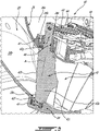
Fig. 3 is a three dimensional cutaway view of a portion of a variable guide vane (VGV) assembly in accordance with one embodiment to be used with the engine ofFig. 1 ; -
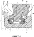
Fig. 4 is an enlarged view of a portion ofFig. 3 ; and -
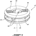
Fig. 5 is a three dimensional view of a bushing in accordance with one embodiment for the VGV assembly ofFig. 3 . - The following disclosure relates generally to gas turbine engines, and more particularly to assemblies including one or more struts and variable orientation guide vanes as may be present in a compressor section and/or in a turbine section of a gas turbine engine. In some embodiments, the assemblies and methods disclosed herein may promote better performance of gas turbine engines, such as by improving flow conditions in the compressor section in some operating conditions, improving the operable range of the compressor, reducing energy losses and aerodynamic loading on rotors.
-
Fig. 1 illustrates a gas turbine engine 10 of a type preferably provided for use in subsonic flight, and in driving engagement with a rotatable load, which is depicted as apropeller 12. The gas turbine engine has in serial flow communication acompressor section 14 for pressurizing the air, acombustor 16 in which the compressed air is mixed with fuel and ignited for generating an annular stream of hot combustion gases, and aturbine section 18 for extracting energy from the combustion gases. - It should be noted that the terms "upstream" and "downstream" used herein refer to the direction of an air/gas flow passing through an
annular gaspath 20 of the gas turbine engine 10. It should also be noted that the term "axial", "radial", "angular" and "circumferential" are used with respect to acentral axis 11 of thegaspath 20, which may also be a central axis of gas turbine engine 10. The gas turbine engine 10 is depicted as a reverse-flow engine in which the air flows in theannular gaspath 20 from a rear of the engine 10 to a front of the engine 10 relative to a direction of travel T of the engine 10. This is opposite than a through-flow engine in which the air flows within thegaspath 20 in a direction opposite the direction of travel T, from the front of the engine towards the rear of the engine 10. The principles of the present disclosure may apply to reverse-flow and through-flow engines and to any other gas turbine engines, such as a turbofan engine and a turboshaft engine. - Referring now to
Fig. 2 , an enlarged view of a portion of thecompressor section 14 is shown. Thecompressor section 14 includes a plurality of stages, namely three in the embodiment shown although more or less than three stages is contemplated, each stage including astator 22 and arotor 24. Therotors 24 are rotatable relative to thestators 22 about thecentral axis 11. Each of thestators 22 includes a plurality ofvanes 23 circumferentially distributed about thecentral axis 11 and extending into theannular gaspath 20. Each of therotors 24 also includes a plurality ofblades 25 circumferentially distributed around thecentral axis 11 and extending into thegaspath 20. Therotors 24 and thus theblades 25 are thereof rotating about thecentral axis 11. As will be seen in further detail below, at least one of thestators 22 includesvanes 23 which are variable guide vanes (VGVs) and thus includes a variableguide vane assembly 40 as will be described. - In the depicted embodiment, the
annular gaspath 20 is defined radially between an outer casing orwall 26 and an inner casing orwall 28. Thevanes 23 and theblades 25 extend radially relative to thecentral axis 11 between the outer andinner casings central axis 11, but is intended to encompass a direction of extension that has a radial component relative to thecentral axis 11. Thevanes 23 can be fixed orientation or variable orientation guide vanes (referred hereinafter as VGVs). Examples of rotors include fans, compressor rotors (e.g. impellers), and turbine rotors (e.g. those downstream of the combustion chamber). - Referring to
Fig. 3 , an example of a variable guide vane (VGV) assembly of astator 22 of the engine 10 is shown at 40. Any of thestators 22 of thecompressor section 14 depicted inFig. 2 may be embodied as avariable guide vane 40. It will be appreciated that, in some cases, theVGV assembly 40 may be used as a stator of theturbine section 18 of the engine 10 without departing from the scope of the present disclosure. TheVGV assembly 40 may be located at an upstream most location L1 (Fig. 2 ) of thecompressor section 14. That is, theVGV assembly 40 may be a variable inlet guide vane assembly. - The
VGV assembly 40 includes a plurality ofvanes 42 circumferentially distributed about the central axis 11 (Fig. 2 ) and extending radially between the inner casing 28 (Fig. 2 ) and theouter casing 26. In the present embodiment, thevanes 42 are rotatably supported at both of their ends by the inner andouter casings vanes 42 has anairfoil 42a having a leadingedge 42b and atrailing edge 42c both extending along a span of theairfoil 42a. Each of thevanes 42 has aninner pivot member 42f at an inner end of theairfoil 42a and anouter pivot member 42g at an outer end of theairfoil 42a. The inner andouter pivot members outer pivot members vanes 42 are rotatable about respective spanwise axes A to change an angle of attack defined between thevanes 42 and a flow flowing within theannular gaspath 20. In the embodiment shown, the spanwise axes A extend between the inner andouter stems vanes 42. - In the embodiment shown, the inner and
outer pivot members outer stems - In the embodiment shown, the outer stems 42g of the
vanes 42 are secured to vanearms 43. Thevane arms 43 are engaged bypins 44 mounted on aunison ring 45 that is rollingly engaged to theouter casing 26 for rotation relative to theouter casing 26 about thecentral axis 11. Theunison ring 45 is drivingly engaged by an actuator, such as a hydraulic actuator. Powering the actuator results in the rotation of theunison ring 45 about thecentral axis 11 and in a sliding motion of thepins 44 within slots defined by thevane arms 43. This result in the rotation of thevanes 42 about their respective spanwise axis A for changing the angle of attack defined between thevanes 42 and the flow flowing in to theannular gas path 20. More detail about theunison ring 45 and thevane arms 43 are presented inU.S. patent application number 17/108,937 filed on December 1, 2020 - Referring now to
Fig. 4 , theinner casing 28 defines a plurality ofpockets 28a that are circumferentially distributed about thecentral axis 11. Thepockets 28a extends from agaspath surface 28b of theinner casing 28 toward thecentral axis 11. Thepockets 28a are therefore recessed from theannular gaspath 20. Theinner casing 28 definesperipheral walls 28c. Each of theperipheral walls 28c extends circumferentially around a respective one of the spanwise axes A of thevanes 42 and circumscribes a respective one of thepockets 28a. It will be understood that similar pockets may be defined by theouter casing 26 of the engine 10. - The variable
guide vane assembly 40 further includesbushings 46. Each of thepockets 28a is sized to receive therein a respective one of thebushings 46. Thebushings 46 are rollingly engaged by the inner stems 42f of thevanes 42. In the embodiment shown, the inner stems 42f of thevanes 42 protrude from shoulders 42s of thevanes 42. The shoulders 42s may be annular and are in abutment against annular faces of thebushings 46. Thebushings 46 may therefore axially locate thevanes 42 relative to theinner casing 28. A radial gap remains between theinner stem 42f and thebushing 46 to allow relative rotation about the bushing axis B. Also, a radial gap is present between thebushings 46 and theperipheral walls 28c of thepockets 28a to accommodate tolerance stack-up and thermal growth. - The
bushings 46 may remain substantially stationary relative to theinner casing 28 and the inner stems 42f may rotate relative to thebushings 46. To this effect, thebushings 46 may be made of any suitable material able to assist rotation of thevanes 42. For instance thebushings 46 may be made of compression molding composite materials. For instance, thebushings 46 may be made of polyamide with 40% carbon fill. Any other suitable composite material may be used. Other materials may be used, such as, graphite, Teflon™, metallic materials, metallic materials impregnated with oil/graphite. Any suitable material that meets the mechanical properties requirements may be used. Materials having tribology properties, such as self-lubricating materials, may be used. - In use, the air flowing in the
annular gas path 22 applies forces on thevanes 42. These forces combined with the loose fits between the inner stems 42f and thebushings 46 and between thebushings 46 and theperipheral walls 28c of thepockets 28a may result in thebushings 46 impacting theperipheral walls 28c of theinner casing 28 and may result in increased vibrations. Also, the loose fit between thebushings 46 and theperipheral walls 28c of thepockets 28a allows rotation of thebushings 46 within thepockets 28a. With time, this may cause fretting and premature wear of theinner casing 28. Theinner casing 28 may be expensive to replace, and may be a non-replaceable part. - Still referring to
Fig. 4 , to at least partially alleviate the aforementioned drawbacks,resilient members 50 are disposed radially between surfaces of theinner casing 28 and thebushings 46 relative to the spanwise axes A of thevanes 42. Theresilient members 50 may be annular and are in abutment against both of the surfaces of theinner casing 28 and thebushings 46. In the embodiment shown, theresilient members 50 are in abutment against theperipheral walls 28c of theinner casing 28 within thepockets 28a and thebushings 46. Theresilient members 50 may be biased or compressed in a radial direction relative to the spanwise axes A by theperipheral walls 28c of thepockets 28a and by thebushings 46. Theresilient members 50 may be any suitable means able to exert a radial force on thebushings 46. Theresilient members 50 is depicted here as a sealing member, such as an O-ring. However, any suitable sealing member may be used. Theresilient member 50 may be made of an elastomeric material. Alternatively, theresilient member 50 may be a metallic C-seal or a split C-seal. Theresilient members 50 may assist in locating, centering, and holding thebushings 46 into thepockets 28a thereby minimizing contacts between thebushings 46 and theperipheral wall 28c. Theresilient members 50 may further inhibit rotation of thebushings 46 within thepockets 28a. Theresilient members 50 are resilient to take up the tolerance stack-up and are able to accommodate thermal growth when the engine 10 is in operation. That is, thebushings 46 may be substantially free of contact with theperipheral walls 28c of theinner casing 28 thanks to theresilient members 50. - The
resilient member 50 is used to accommodate a tolerance stack-up and for centering thebushings 46 relative to thepockets 28a to limit contact between thebushings 46 and theperipheral walls 28c circumscribing saidpockets 28a. In the present embodiment, thepockets 28a do not extend through theinner casing 28. Theresilient members 50 are therefore not used for sealing. However, in some other embodiments, theresilient members 50 may contribute in limiting air from leaking out of theannular gaspath 22 if sealing members are used as theresilient members 50. - Referring now to
Fig. 5 , one of thebushing 46 is shown in detail. Since the below description may apply to all of thebushings 46, the singular form is used. Thebushing 46 includes abody 46a that is annularly extending around a bushing axis B. In the embodiment shown, thebody 46a is a single monolithic piece, but may alternatively include more than one pieces assembled together using any suitable means such as, glue, fasteners, lap joints, and so on. Thebody 46a defines an innercircumferential face 46b, an outercircumferential face 46c that is located radially outwardly of the innercircumferential face 46b relative to the bushing axis B. The innercircumferential face 46b bounds an aperture of thebushing 46 that is sized to accept theinner stem 42f of thevane 42. Thebody 46a defines a topannular face 46d and a bottomannular face 46e. The top and bottom annular faces 46d, 46e extend radially relative to the bushing axis B from the innercircumferential face 46b to the outercircumferential face 46c. The topannular face 46d is engaged by the shoulder 42s (Fig. 4 ) of thevane 42. The bottomannular face 46e engages a bottom wall of theinner casing 28; the bottom wall being located in thepockets 28a. In the embodiment shown, chamfers are present at intersection between theannular faces bushing 46 in a respective one of thepockets 28a (Fig. 4 ) and the insertion of thestem 42f into thebushing 46. - In the depicted embodiment, the
body 46a of thebushing 46 defines anannular groove 46f that extends radially from the outercircumferential face 46c toward the innercircumferential face 46b. Thegroove 46f is sized to accept theresilient member 50. Therefore, movements of theresilient member 50 relative to thebushing 46 in a direction parallel to the bushing axis B may be substantially limited by thegroove 46f. A depth of thegroove 46f taken in a radial direction relative to the bushing axis B may be less than a diameter of theresilient member 50. In other words, thegroove 46f may be sized such that a portion of theresilient member 50 protrudes radially outwardly beyond the outercircumferential face 46c of thebody 46a to ensure that theresilient member 50 contacts theperipheral walls 28c (Fig. 4 ) of theinner casing 28 rather than thebushing 46 contacting saidperipheral walls 28c. In an alternate embodiment, the groove may be defined by theperipheral wall 28c of thepocket 28a and the resilient member may be engaged to theperipheral wall 28c within the groove. In an alternate embodiment, both of thebushing 46 and theperipheral wall 28c may define a groove. In some other embodiments, theresilient member 50 may be recessed into the groove or aligned with the outercircumferential face 46c of thebushing 46; theperipheral wall 28c defining an annular bump in register with the groove such that theresilient member 50 contacts the annular bump before the bushing contacts theperipheral wall 28c. - Still referring to
Fig. 5 , thebody 46a of thebushing 46 further defines at least onebore 46g, twobores 46g in the depicted embodiment, that extend in a direction having a radial component relative to the bushing axis B from the innercircumferential face 46b to thegroove 46f. Thesebores 46g are sized to accept a tool to remove theresilient member 50 from thegroove 46f during maintenance. - Referring back to
Fig. 3 , in the embodiment shown theouter casing 26 includes afirst section 26a and asecond section 26b secured to thefirst section 26a. Thesecond section 26b is used to rollingly support theunison ring 45 and defines a plurality ofapertures 26c that are circumferentially distributed about thecentral axis 11. Theapertures 26c are sized to receiveouter bushings 47. A sealingmember 48 is received radially between the outer stems 42g and theouter bushings 47. The sealingmember 48 is shown here as an O-ring, but any other suitable sealing members may be used. The sealingmember 48 is used to limit air from leaking out of theannular pas path 22 via gaps between theouter bushings 47 and the outer stems 42g. In this case, the wear of thesecond section 26b of theouter casing 26 caused by movements of theouter bushings 47 into theapertures 26c of theouter casing 26 either caused by the air flowing into the annular gaspath 22 and/or by rotation of the outer stems 42g relative to theouter bushings 47 may be acceptable because it may be less time consuming to replace thesecond section 26b of theouter casing 26 than theinner casing 28. It will nevertheless be appreciated that resilient members as described herein above may be disposed between theouter bushings 47 and peripheral walls circumscribing theapertures 26c of theouter casing 26. - The presence of the
resilient member 50 may dampen vibrations and may reduce the risk of fretting and wear caused by thebushing 46 rotating within theinner shroud pocket 28a. Theresilient member 50 may also allow for thebushing 46 andshroud 28 to maintain their fit over a wider thermal range than a configuration lacking such a resilient member. This may introduce the possibility of using materials with a larger difference in their thermal coefficients. The proposed design can be retrofitted to existing VGV systems. The proposed design may be especially useful in engines where theinner shroud 28 that holds thebushings 46 is an expensive component. By reducing fretting between the bushing and shroud, there may be less likelihood that the expensive shroud will need to be replaced from wear. - The embodiments described in this document provide non-limiting examples of possible implementations of the present technology. Upon review of the present disclosure, a person of ordinary skill in the art will recognize that changes may be made to the embodiments described herein without departing from the scope of the present technology. For example, the disclosed bushings with resilient member may be received within pockets defined by the outer casing for rotatably supporting outer stems of the vanes. Also, the variable guide vane assembly has been disclosed as being part of the compressor section of the engine, but may also or in alternatively be part of the turbine section of the engine. Yet further modifications could be implemented by a person of ordinary skill in the art in view of the present disclosure, which modifications would be within the scope of the present technology.
Claims (13)
- A vane bushing assembly for a variable guide vane assembly (40) of a gas turbine engine (10), comprising:a bushing (46) having an annular body (46a) extending circumferentially around a bushing axis (B), the annular body (46a) defined radially between a first circumferential surface (46b) and a second circumferential surface (46c) relative to the bushing axis (B), the first circumferential surface (46b) sized to be rollingly engaged by a vane (42) of the variable guide vane assembly (40); anda resilient member (50) extending around the bushing axis (B) of the bushing (46) and engaged to the second circumferential surface (46c).
- The vane bushing assembly of claim 1, wherein the resilient member (50) is a sealing member.
- A variable guide vane (VGV) assembly (40) of a gas turbine engine (10), comprising:variable guide vanes (42) circumferentially distributed about a central axis (11), the variable guide vanes (42) having airfoils (42a) extending between first and second pivot members (42f, 42g) at respective first and second ends of the airfoils (42a), the variable guide vanes (42) rotatable about respective spanwise axes (A); anda plurality of vane bushing assemblies as defined by claim 1 or 2, the bushings (46) of the vane bushing assemblies sized to be received within pockets (28a) of a casing (28) of the gas turbine engine (10), the first pivot members (42f) of the variable guide vanes (42) rollingly engaged to the bushings (46).
- The vane bushing assembly or VGV assembly (40) of any preceding claim, wherein the sealing or resilient member (50) is made of an elastomeric material.
- The vane bushing assembly or VGV assembly (40) of any preceding claim, wherein the sealing or resilient member (50) is a C-seal or a O-ring.
- The VGV assembly (40) of any of claims 3 to 5, wherein the bushings (46) of the vane bushing assemblies define grooves (46f) extending circumferentially around the spanwise axes (A), each of the sealing members (50) received within a respective one of the grooves (46f).
- The VGV assembly (40) of any of claims 3 to 6, wherein the first pivot members (42f) are stems protruding from the airfoils (42a) along the spanwise axes (A), the stems (42f) rollingly engaged to the bushings (46) by being rotatably received within apertures defined by the bushings (46).
- The VGV assembly (40) of claim 7, wherein the bushings (46) define bores (46g) extending outwardly from the apertures to the second circumferential faces (46c) of the bushings (46), the bores (46g) sized to receive a tool for removing the sealing or resilient members (50).
- A gas turbine engine (10), comprising:an annular gaspath (20) extending around a central axis (11), the annular gaspath (20) defined between a first casing (28) and a second casing (26), the first casing (28) defining pockets (28a); anda variable guide vane assembly (40) as defined in any one of claims 3 to 8.
- The gas turbine engine (10) of claim 9, wherein the surfaces of the first casing (28) are defined by peripheral walls (28c) of the first casing (28), each of the peripheral walls (28c) circumscribing a respective one of the pockets (28a).
- The gas turbine engine (10) of claim 10, wherein the resilient or sealing members (50) are disposed radially between the peripheral walls (28c) and the bushings (46) relative to the spanwise axes (A).
- The gas turbine engine (10) of any of claims 9 to 11, wherein the first casing (28) is located radially inwardly of the second casing (26) relative to the central axis (11).
- The gas turbine engine (10) of any of claims 9 to 12, wherein the first casing (28) is made of a metallic material and the bushings (46) are made of a composite material.
Applications Claiming Priority (1)
| Application Number | Priority Date | Filing Date | Title |
|---|---|---|---|
| US17/170,140 US11624293B2 (en) | 2021-02-08 | 2021-02-08 | Variable guide vane assembly and bushing therefor |
Publications (2)
| Publication Number | Publication Date |
|---|---|
| EP4039943A1 true EP4039943A1 (en) | 2022-08-10 |
| EP4039943B1 EP4039943B1 (en) | 2023-12-20 |
Family
ID=80222459
Family Applications (1)
| Application Number | Title | Priority Date | Filing Date |
|---|---|---|---|
| EP22155484.3A Active EP4039943B1 (en) | 2021-02-08 | 2022-02-07 | Gas turbine engine |
Country Status (3)
| Country | Link |
|---|---|
| US (1) | US11624293B2 (en) |
| EP (1) | EP4039943B1 (en) |
| CA (1) | CA3146757A1 (en) |
Families Citing this family (5)
| Publication number | Priority date | Publication date | Assignee | Title |
|---|---|---|---|---|
| US11834960B2 (en) * | 2022-02-18 | 2023-12-05 | General Electric Company | Methods and apparatus to reduce deflection of an airfoil |
| US12044135B1 (en) * | 2023-11-06 | 2024-07-23 | Pratt & Whitney Canada Corp. | Stator vane with variable center of gravity |
| US12055153B1 (en) * | 2023-12-05 | 2024-08-06 | General Electric Company | Variable pitch airfoil assembly for an open fan rotor of an engine having a damping element |
| US12435644B1 (en) * | 2024-12-20 | 2025-10-07 | General Electric Company | Gas turbine engines with inlet guide vanes |
| US12460557B1 (en) | 2025-01-23 | 2025-11-04 | General Electric Company | Variable pitch airfoil assembly for a gas turbine engine |
Citations (4)
| Publication number | Priority date | Publication date | Assignee | Title |
|---|---|---|---|---|
| US5636968A (en) * | 1994-08-10 | 1997-06-10 | Societe Nationale D'etude Et De Construction De Moteurs D'aviation "Snecma" | Device for assembling a circular stage of pivoting vanes |
| US20140234085A1 (en) * | 2013-02-15 | 2014-08-21 | United Technologies Corporation | Bushing arranged between a body and a shaft, and connected to the shaft |
| US20180058231A1 (en) * | 2016-08-23 | 2018-03-01 | MTU Aero Engines AG | Inner ring for an annular guide vane assembly of a turbomachine |
| US20190017408A1 (en) * | 2017-07-14 | 2019-01-17 | United Technologies Corporation | Gas turbine engine variable vane end wall insert |
Family Cites Families (7)
| Publication number | Priority date | Publication date | Assignee | Title |
|---|---|---|---|---|
| US2956841A (en) * | 1957-01-30 | 1960-10-18 | Westinghouse Electric Corp | Bearing and mounting therefor |
| US3079128A (en) * | 1961-01-23 | 1963-02-26 | Burge Joseph | Sealing and securing means for turbomachine blading |
| US7121727B2 (en) * | 2002-12-24 | 2006-10-17 | General Electric Company | Inlet guide vane bushing having extended life expectancy |
| US7753647B2 (en) * | 2005-07-20 | 2010-07-13 | United Technologies Corporation | Lightweight cast inner diameter vane shroud for variable stator vanes |
| US20090200793A1 (en) * | 2008-02-07 | 2009-08-13 | National Coupling Company, Inc. | Crown seal with integral sealing projections for undersea hydraulic couplings |
| US9074489B2 (en) * | 2012-03-26 | 2015-07-07 | Pratt & Whitney Canada Corp. | Connector assembly for variable inlet guide vanes and method |
| US11441426B2 (en) * | 2020-04-30 | 2022-09-13 | Hamilton Sundstrand Corporation | Valve assembly configured with manifold having eutectic plug |
-
2021
- 2021-02-08 US US17/170,140 patent/US11624293B2/en active Active
-
2022
- 2022-01-26 CA CA3146757A patent/CA3146757A1/en active Pending
- 2022-02-07 EP EP22155484.3A patent/EP4039943B1/en active Active
Patent Citations (4)
| Publication number | Priority date | Publication date | Assignee | Title |
|---|---|---|---|---|
| US5636968A (en) * | 1994-08-10 | 1997-06-10 | Societe Nationale D'etude Et De Construction De Moteurs D'aviation "Snecma" | Device for assembling a circular stage of pivoting vanes |
| US20140234085A1 (en) * | 2013-02-15 | 2014-08-21 | United Technologies Corporation | Bushing arranged between a body and a shaft, and connected to the shaft |
| US20180058231A1 (en) * | 2016-08-23 | 2018-03-01 | MTU Aero Engines AG | Inner ring for an annular guide vane assembly of a turbomachine |
| US20190017408A1 (en) * | 2017-07-14 | 2019-01-17 | United Technologies Corporation | Gas turbine engine variable vane end wall insert |
Also Published As
| Publication number | Publication date |
|---|---|
| US11624293B2 (en) | 2023-04-11 |
| EP4039943B1 (en) | 2023-12-20 |
| CA3146757A1 (en) | 2022-08-08 |
| US20220251967A1 (en) | 2022-08-11 |
Similar Documents
| Publication | Publication Date | Title |
|---|---|---|
| EP4039943B1 (en) | Gas turbine engine | |
| EP4008884B1 (en) | Variable guide vane assembly for a gas turbine engine and gas turbine engine | |
| EP4001596B1 (en) | Gas turbine engine | |
| US11767768B2 (en) | Unison member for variable guide vane | |
| EP2971693B1 (en) | Gas turbine engine rotor disk-seal arrangement | |
| US10718270B2 (en) | Hydrostatic non-contact seal with dual material | |
| EP2971736B1 (en) | Interblade metal platform for ceramic matrix composite turbine blades | |
| CN107435592B (en) | Inter-shaft sealing system for gas turbine engine and method of assembling same | |
| US11725533B2 (en) | Variable guide vane assembly and bushing ring therefor | |
| US9856740B2 (en) | Tip-controlled integrally bladed rotor for gas turbine engine | |
| CN108691568B (en) | Turbine interstage frame for a gas turbine engine | |
| EP3460196B1 (en) | Bearing assembly for a variable stator vane | |
| US11512602B2 (en) | Seal element for sealing a joint between a rotor blade and a rotor disk | |
| EP4043698A1 (en) | Variable guide vane assembly for a gas turbine engine and gas turbine engine | |
| EP4317657A1 (en) | Variable guide vane assembly for gas turbine engine | |
| EP3249166A1 (en) | Turbine shroud | |
| US12044135B1 (en) | Stator vane with variable center of gravity | |
| WO2022051760A1 (en) | Guide vane in gas turbine engine |
Legal Events
| Date | Code | Title | Description |
|---|---|---|---|
| PUAI | Public reference made under article 153(3) epc to a published international application that has entered the european phase |
Free format text: ORIGINAL CODE: 0009012 |
|
| STAA | Information on the status of an ep patent application or granted ep patent |
Free format text: STATUS: THE APPLICATION HAS BEEN PUBLISHED |
|
| AK | Designated contracting states |
Kind code of ref document: A1 Designated state(s): AL AT BE BG CH CY CZ DE DK EE ES FI FR GB GR HR HU IE IS IT LI LT LU LV MC MK MT NL NO PL PT RO RS SE SI SK SM TR |
|
| STAA | Information on the status of an ep patent application or granted ep patent |
Free format text: STATUS: REQUEST FOR EXAMINATION WAS MADE |
|
| 17P | Request for examination filed |
Effective date: 20230210 |
|
| RBV | Designated contracting states (corrected) |
Designated state(s): AL AT BE BG CH CY CZ DE DK EE ES FI FR GB GR HR HU IE IS IT LI LT LU LV MC MK MT NL NO PL PT RO RS SE SI SK SM TR |
|
| GRAP | Despatch of communication of intention to grant a patent |
Free format text: ORIGINAL CODE: EPIDOSNIGR1 |
|
| STAA | Information on the status of an ep patent application or granted ep patent |
Free format text: STATUS: GRANT OF PATENT IS INTENDED |
|
| RIC1 | Information provided on ipc code assigned before grant |
Ipc: F01D 11/00 20060101ALN20230607BHEP Ipc: F01D 25/06 20060101ALN20230607BHEP Ipc: F01D 17/16 20060101AFI20230607BHEP |
|
| INTG | Intention to grant announced |
Effective date: 20230630 |
|
| GRAS | Grant fee paid |
Free format text: ORIGINAL CODE: EPIDOSNIGR3 |
|
| GRAA | (expected) grant |
Free format text: ORIGINAL CODE: 0009210 |
|
| STAA | Information on the status of an ep patent application or granted ep patent |
Free format text: STATUS: THE PATENT HAS BEEN GRANTED |
|
| AK | Designated contracting states |
Kind code of ref document: B1 Designated state(s): AL AT BE BG CH CY CZ DE DK EE ES FI FR GB GR HR HU IE IS IT LI LT LU LV MC MK MT NL NO PL PT RO RS SE SI SK SM TR |
|
| REG | Reference to a national code |
Ref country code: GB Ref legal event code: FG4D |
|
| REG | Reference to a national code |
Ref country code: CH Ref legal event code: EP |
|
| REG | Reference to a national code |
Ref country code: DE Ref legal event code: R096 Ref document number: 602022001319 Country of ref document: DE |
|
| REG | Reference to a national code |
Ref country code: IE Ref legal event code: FG4D |
|
| PG25 | Lapsed in a contracting state [announced via postgrant information from national office to epo] |
Ref country code: GR Free format text: LAPSE BECAUSE OF FAILURE TO SUBMIT A TRANSLATION OF THE DESCRIPTION OR TO PAY THE FEE WITHIN THE PRESCRIBED TIME-LIMIT Effective date: 20240321 |
|
| REG | Reference to a national code |
Ref country code: LT Ref legal event code: MG9D |
|
| PG25 | Lapsed in a contracting state [announced via postgrant information from national office to epo] |
Ref country code: LT Free format text: LAPSE BECAUSE OF FAILURE TO SUBMIT A TRANSLATION OF THE DESCRIPTION OR TO PAY THE FEE WITHIN THE PRESCRIBED TIME-LIMIT Effective date: 20231220 |
|
| REG | Reference to a national code |
Ref country code: NL Ref legal event code: MP Effective date: 20231220 |
|
| PG25 | Lapsed in a contracting state [announced via postgrant information from national office to epo] |
Ref country code: ES Free format text: LAPSE BECAUSE OF FAILURE TO SUBMIT A TRANSLATION OF THE DESCRIPTION OR TO PAY THE FEE WITHIN THE PRESCRIBED TIME-LIMIT Effective date: 20231220 |
|
| PG25 | Lapsed in a contracting state [announced via postgrant information from national office to epo] |
Ref country code: LT Free format text: LAPSE BECAUSE OF FAILURE TO SUBMIT A TRANSLATION OF THE DESCRIPTION OR TO PAY THE FEE WITHIN THE PRESCRIBED TIME-LIMIT Effective date: 20231220 Ref country code: GR Free format text: LAPSE BECAUSE OF FAILURE TO SUBMIT A TRANSLATION OF THE DESCRIPTION OR TO PAY THE FEE WITHIN THE PRESCRIBED TIME-LIMIT Effective date: 20240321 Ref country code: FI Free format text: LAPSE BECAUSE OF FAILURE TO SUBMIT A TRANSLATION OF THE DESCRIPTION OR TO PAY THE FEE WITHIN THE PRESCRIBED TIME-LIMIT Effective date: 20231220 Ref country code: ES Free format text: LAPSE BECAUSE OF FAILURE TO SUBMIT A TRANSLATION OF THE DESCRIPTION OR TO PAY THE FEE WITHIN THE PRESCRIBED TIME-LIMIT Effective date: 20231220 Ref country code: BG Free format text: LAPSE BECAUSE OF FAILURE TO SUBMIT A TRANSLATION OF THE DESCRIPTION OR TO PAY THE FEE WITHIN THE PRESCRIBED TIME-LIMIT Effective date: 20240320 |
|
| REG | Reference to a national code |
Ref country code: AT Ref legal event code: MK05 Ref document number: 1642619 Country of ref document: AT Kind code of ref document: T Effective date: 20231220 |
|
| PG25 | Lapsed in a contracting state [announced via postgrant information from national office to epo] |
Ref country code: NL Free format text: LAPSE BECAUSE OF FAILURE TO SUBMIT A TRANSLATION OF THE DESCRIPTION OR TO PAY THE FEE WITHIN THE PRESCRIBED TIME-LIMIT Effective date: 20231220 |
|
| PG25 | Lapsed in a contracting state [announced via postgrant information from national office to epo] |
Ref country code: SE Free format text: LAPSE BECAUSE OF FAILURE TO SUBMIT A TRANSLATION OF THE DESCRIPTION OR TO PAY THE FEE WITHIN THE PRESCRIBED TIME-LIMIT Effective date: 20231220 Ref country code: RS Free format text: LAPSE BECAUSE OF FAILURE TO SUBMIT A TRANSLATION OF THE DESCRIPTION OR TO PAY THE FEE WITHIN THE PRESCRIBED TIME-LIMIT Effective date: 20231220 Ref country code: NO Free format text: LAPSE BECAUSE OF FAILURE TO SUBMIT A TRANSLATION OF THE DESCRIPTION OR TO PAY THE FEE WITHIN THE PRESCRIBED TIME-LIMIT Effective date: 20240320 Ref country code: NL Free format text: LAPSE BECAUSE OF FAILURE TO SUBMIT A TRANSLATION OF THE DESCRIPTION OR TO PAY THE FEE WITHIN THE PRESCRIBED TIME-LIMIT Effective date: 20231220 Ref country code: LV Free format text: LAPSE BECAUSE OF FAILURE TO SUBMIT A TRANSLATION OF THE DESCRIPTION OR TO PAY THE FEE WITHIN THE PRESCRIBED TIME-LIMIT Effective date: 20231220 Ref country code: HR Free format text: LAPSE BECAUSE OF FAILURE TO SUBMIT A TRANSLATION OF THE DESCRIPTION OR TO PAY THE FEE WITHIN THE PRESCRIBED TIME-LIMIT Effective date: 20231220 |
|
| PG25 | Lapsed in a contracting state [announced via postgrant information from national office to epo] |
Ref country code: IS Free format text: LAPSE BECAUSE OF FAILURE TO SUBMIT A TRANSLATION OF THE DESCRIPTION OR TO PAY THE FEE WITHIN THE PRESCRIBED TIME-LIMIT Effective date: 20240420 |
|
| PG25 | Lapsed in a contracting state [announced via postgrant information from national office to epo] |
Ref country code: CZ Free format text: LAPSE BECAUSE OF FAILURE TO SUBMIT A TRANSLATION OF THE DESCRIPTION OR TO PAY THE FEE WITHIN THE PRESCRIBED TIME-LIMIT Effective date: 20231220 Ref country code: AT Free format text: LAPSE BECAUSE OF FAILURE TO SUBMIT A TRANSLATION OF THE DESCRIPTION OR TO PAY THE FEE WITHIN THE PRESCRIBED TIME-LIMIT Effective date: 20231220 |
|
| PG25 | Lapsed in a contracting state [announced via postgrant information from national office to epo] |
Ref country code: SK Free format text: LAPSE BECAUSE OF FAILURE TO SUBMIT A TRANSLATION OF THE DESCRIPTION OR TO PAY THE FEE WITHIN THE PRESCRIBED TIME-LIMIT Effective date: 20231220 |
|
| PG25 | Lapsed in a contracting state [announced via postgrant information from national office to epo] |
Ref country code: SM Free format text: LAPSE BECAUSE OF FAILURE TO SUBMIT A TRANSLATION OF THE DESCRIPTION OR TO PAY THE FEE WITHIN THE PRESCRIBED TIME-LIMIT Effective date: 20231220 Ref country code: SK Free format text: LAPSE BECAUSE OF FAILURE TO SUBMIT A TRANSLATION OF THE DESCRIPTION OR TO PAY THE FEE WITHIN THE PRESCRIBED TIME-LIMIT Effective date: 20231220 Ref country code: RO Free format text: LAPSE BECAUSE OF FAILURE TO SUBMIT A TRANSLATION OF THE DESCRIPTION OR TO PAY THE FEE WITHIN THE PRESCRIBED TIME-LIMIT Effective date: 20231220 Ref country code: IT Free format text: LAPSE BECAUSE OF FAILURE TO SUBMIT A TRANSLATION OF THE DESCRIPTION OR TO PAY THE FEE WITHIN THE PRESCRIBED TIME-LIMIT Effective date: 20231220 Ref country code: IS Free format text: LAPSE BECAUSE OF FAILURE TO SUBMIT A TRANSLATION OF THE DESCRIPTION OR TO PAY THE FEE WITHIN THE PRESCRIBED TIME-LIMIT Effective date: 20240420 Ref country code: EE Free format text: LAPSE BECAUSE OF FAILURE TO SUBMIT A TRANSLATION OF THE DESCRIPTION OR TO PAY THE FEE WITHIN THE PRESCRIBED TIME-LIMIT Effective date: 20231220 Ref country code: CZ Free format text: LAPSE BECAUSE OF FAILURE TO SUBMIT A TRANSLATION OF THE DESCRIPTION OR TO PAY THE FEE WITHIN THE PRESCRIBED TIME-LIMIT Effective date: 20231220 Ref country code: AT Free format text: LAPSE BECAUSE OF FAILURE TO SUBMIT A TRANSLATION OF THE DESCRIPTION OR TO PAY THE FEE WITHIN THE PRESCRIBED TIME-LIMIT Effective date: 20231220 |
|
| PG25 | Lapsed in a contracting state [announced via postgrant information from national office to epo] |
Ref country code: PL Free format text: LAPSE BECAUSE OF FAILURE TO SUBMIT A TRANSLATION OF THE DESCRIPTION OR TO PAY THE FEE WITHIN THE PRESCRIBED TIME-LIMIT Effective date: 20231220 Ref country code: PT Free format text: LAPSE BECAUSE OF FAILURE TO SUBMIT A TRANSLATION OF THE DESCRIPTION OR TO PAY THE FEE WITHIN THE PRESCRIBED TIME-LIMIT Effective date: 20240422 |
|
| PG25 | Lapsed in a contracting state [announced via postgrant information from national office to epo] |
Ref country code: PT Free format text: LAPSE BECAUSE OF FAILURE TO SUBMIT A TRANSLATION OF THE DESCRIPTION OR TO PAY THE FEE WITHIN THE PRESCRIBED TIME-LIMIT Effective date: 20240422 Ref country code: PL Free format text: LAPSE BECAUSE OF FAILURE TO SUBMIT A TRANSLATION OF THE DESCRIPTION OR TO PAY THE FEE WITHIN THE PRESCRIBED TIME-LIMIT Effective date: 20231220 |
|
| REG | Reference to a national code |
Ref country code: DE Ref legal event code: R097 Ref document number: 602022001319 Country of ref document: DE |
|
| PG25 | Lapsed in a contracting state [announced via postgrant information from national office to epo] |
Ref country code: MC Free format text: LAPSE BECAUSE OF FAILURE TO SUBMIT A TRANSLATION OF THE DESCRIPTION OR TO PAY THE FEE WITHIN THE PRESCRIBED TIME-LIMIT Effective date: 20231220 |
|
| PG25 | Lapsed in a contracting state [announced via postgrant information from national office to epo] |
Ref country code: DK Free format text: LAPSE BECAUSE OF FAILURE TO SUBMIT A TRANSLATION OF THE DESCRIPTION OR TO PAY THE FEE WITHIN THE PRESCRIBED TIME-LIMIT Effective date: 20231220 |
|
| PG25 | Lapsed in a contracting state [announced via postgrant information from national office to epo] |
Ref country code: LU Free format text: LAPSE BECAUSE OF NON-PAYMENT OF DUE FEES Effective date: 20240207 |
|
| PLBE | No opposition filed within time limit |
Free format text: ORIGINAL CODE: 0009261 |
|
| STAA | Information on the status of an ep patent application or granted ep patent |
Free format text: STATUS: NO OPPOSITION FILED WITHIN TIME LIMIT |
|
| PG25 | Lapsed in a contracting state [announced via postgrant information from national office to epo] |
Ref country code: SI Free format text: LAPSE BECAUSE OF FAILURE TO SUBMIT A TRANSLATION OF THE DESCRIPTION OR TO PAY THE FEE WITHIN THE PRESCRIBED TIME-LIMIT Effective date: 20231220 |
|
| PG25 | Lapsed in a contracting state [announced via postgrant information from national office to epo] |
Ref country code: SI Free format text: LAPSE BECAUSE OF FAILURE TO SUBMIT A TRANSLATION OF THE DESCRIPTION OR TO PAY THE FEE WITHIN THE PRESCRIBED TIME-LIMIT Effective date: 20231220 Ref country code: LU Free format text: LAPSE BECAUSE OF NON-PAYMENT OF DUE FEES Effective date: 20240207 Ref country code: DK Free format text: LAPSE BECAUSE OF FAILURE TO SUBMIT A TRANSLATION OF THE DESCRIPTION OR TO PAY THE FEE WITHIN THE PRESCRIBED TIME-LIMIT Effective date: 20231220 |
|
| 26N | No opposition filed |
Effective date: 20240923 |
|
| REG | Reference to a national code |
Ref country code: BE Ref legal event code: MM Effective date: 20240229 |
|
| PG25 | Lapsed in a contracting state [announced via postgrant information from national office to epo] |
Ref country code: BE Free format text: LAPSE BECAUSE OF NON-PAYMENT OF DUE FEES Effective date: 20240229 |
|
| PG25 | Lapsed in a contracting state [announced via postgrant information from national office to epo] |
Ref country code: IE Free format text: LAPSE BECAUSE OF NON-PAYMENT OF DUE FEES Effective date: 20240207 |
|
| PG25 | Lapsed in a contracting state [announced via postgrant information from national office to epo] |
Ref country code: IE Free format text: LAPSE BECAUSE OF NON-PAYMENT OF DUE FEES Effective date: 20240207 Ref country code: BE Free format text: LAPSE BECAUSE OF NON-PAYMENT OF DUE FEES Effective date: 20240229 |
|
| PG25 | Lapsed in a contracting state [announced via postgrant information from national office to epo] |
Ref country code: CY Free format text: LAPSE BECAUSE OF FAILURE TO SUBMIT A TRANSLATION OF THE DESCRIPTION OR TO PAY THE FEE WITHIN THE PRESCRIBED TIME-LIMIT; INVALID AB INITIO Effective date: 20220207 |
|
| REG | Reference to a national code |
Ref country code: CH Ref legal event code: PL |
|
| PG25 | Lapsed in a contracting state [announced via postgrant information from national office to epo] |
Ref country code: CH Free format text: LAPSE BECAUSE OF NON-PAYMENT OF DUE FEES Effective date: 20250228 |
|
| PG25 | Lapsed in a contracting state [announced via postgrant information from national office to epo] |
Ref country code: TR Free format text: LAPSE BECAUSE OF FAILURE TO SUBMIT A TRANSLATION OF THE DESCRIPTION OR TO PAY THE FEE WITHIN THE PRESCRIBED TIME-LIMIT Effective date: 20231220 |
|
| P01 | Opt-out of the competence of the unified patent court (upc) registered |
Free format text: CASE NUMBER: UPC_APP_0000178_4039943/2026 Effective date: 20260105 |
|
| PGFP | Annual fee paid to national office [announced via postgrant information from national office to epo] |
Ref country code: GB Payment date: 20260122 Year of fee payment: 5 |
|
| PGFP | Annual fee paid to national office [announced via postgrant information from national office to epo] |
Ref country code: DE Payment date: 20260121 Year of fee payment: 5 |
|
| PGFP | Annual fee paid to national office [announced via postgrant information from national office to epo] |
Ref country code: FR Payment date: 20260121 Year of fee payment: 5 |