EP4039875A1 - Laundry treating apparatus - Google Patents
Laundry treating apparatus Download PDFInfo
- Publication number
- EP4039875A1 EP4039875A1 EP22154681.5A EP22154681A EP4039875A1 EP 4039875 A1 EP4039875 A1 EP 4039875A1 EP 22154681 A EP22154681 A EP 22154681A EP 4039875 A1 EP4039875 A1 EP 4039875A1
- Authority
- EP
- European Patent Office
- Prior art keywords
- water
- channel
- drum
- connective
- face
- Prior art date
- Legal status (The legal status is an assumption and is not a legal conclusion. Google has not performed a legal analysis and makes no representation as to the accuracy of the status listed.)
- Pending
Links
- XLYOFNOQVPJJNP-UHFFFAOYSA-N water Substances O XLYOFNOQVPJJNP-UHFFFAOYSA-N 0.000 claims abstract description 522
- 238000004140 cleaning Methods 0.000 claims abstract description 234
- 238000004891 communication Methods 0.000 claims description 87
- 238000007789 sealing Methods 0.000 claims description 82
- 238000003860 storage Methods 0.000 claims description 38
- 238000012546 transfer Methods 0.000 claims description 35
- 230000002452 interceptive effect Effects 0.000 claims description 4
- 239000008400 supply water Substances 0.000 claims description 4
- 238000007599 discharging Methods 0.000 claims description 2
- 239000003638 chemical reducing agent Substances 0.000 description 172
- 230000008878 coupling Effects 0.000 description 98
- 238000010168 coupling process Methods 0.000 description 98
- 238000005859 coupling reaction Methods 0.000 description 98
- 238000001035 drying Methods 0.000 description 26
- 238000000034 method Methods 0.000 description 23
- 230000008569 process Effects 0.000 description 20
- 239000000126 substance Substances 0.000 description 20
- 238000000638 solvent extraction Methods 0.000 description 17
- 230000003014 reinforcing effect Effects 0.000 description 15
- 230000000694 effects Effects 0.000 description 12
- 238000005406 washing Methods 0.000 description 10
- 239000011324 bead Substances 0.000 description 9
- 238000003466 welding Methods 0.000 description 8
- 238000009434 installation Methods 0.000 description 6
- 238000004519 manufacturing process Methods 0.000 description 6
- 230000007423 decrease Effects 0.000 description 5
- 239000000463 material Substances 0.000 description 5
- 239000003507 refrigerant Substances 0.000 description 5
- 230000008439 repair process Effects 0.000 description 5
- 229910000831 Steel Inorganic materials 0.000 description 4
- 239000010959 steel Substances 0.000 description 4
- 230000005540 biological transmission Effects 0.000 description 3
- 238000012986 modification Methods 0.000 description 3
- 230000004048 modification Effects 0.000 description 3
- 238000005192 partition Methods 0.000 description 3
- 238000003825 pressing Methods 0.000 description 3
- 229920001169 thermoplastic Polymers 0.000 description 3
- 239000004416 thermosoftening plastic Substances 0.000 description 3
- 238000013461 design Methods 0.000 description 2
- 230000006866 deterioration Effects 0.000 description 2
- 238000006073 displacement reaction Methods 0.000 description 2
- 238000001746 injection moulding Methods 0.000 description 2
- 230000033001 locomotion Effects 0.000 description 2
- 239000002245 particle Substances 0.000 description 2
- 238000000926 separation method Methods 0.000 description 2
- 239000007921 spray Substances 0.000 description 2
- 238000013459 approach Methods 0.000 description 1
- 230000008901 benefit Effects 0.000 description 1
- 230000008859 change Effects 0.000 description 1
- 230000008094 contradictory effect Effects 0.000 description 1
- 230000003247 decreasing effect Effects 0.000 description 1
- 239000003599 detergent Substances 0.000 description 1
- 239000000428 dust Substances 0.000 description 1
- 239000012467 final product Substances 0.000 description 1
- 230000005484 gravity Effects 0.000 description 1
- 239000007788 liquid Substances 0.000 description 1
- 230000005389 magnetism Effects 0.000 description 1
- 238000012423 maintenance Methods 0.000 description 1
- 238000011089 mechanical engineering Methods 0.000 description 1
- 239000002184 metal Substances 0.000 description 1
- 238000000465 moulding Methods 0.000 description 1
- 230000001151 other effect Effects 0.000 description 1
- 239000000088 plastic resin Substances 0.000 description 1
- 239000000047 product Substances 0.000 description 1
- 229920006395 saturated elastomer Polymers 0.000 description 1
- 238000004904 shortening Methods 0.000 description 1
- 238000005507 spraying Methods 0.000 description 1
- 238000011144 upstream manufacturing Methods 0.000 description 1
Images


Classifications
-
- D—TEXTILES; PAPER
- D06—TREATMENT OF TEXTILES OR THE LIKE; LAUNDERING; FLEXIBLE MATERIALS NOT OTHERWISE PROVIDED FOR
- D06F—LAUNDERING, DRYING, IRONING, PRESSING OR FOLDING TEXTILE ARTICLES
- D06F58/00—Domestic laundry dryers
- D06F58/20—General details of domestic laundry dryers
-
- D—TEXTILES; PAPER
- D06—TREATMENT OF TEXTILES OR THE LIKE; LAUNDERING; FLEXIBLE MATERIALS NOT OTHERWISE PROVIDED FOR
- D06F—LAUNDERING, DRYING, IRONING, PRESSING OR FOLDING TEXTILE ARTICLES
- D06F58/00—Domestic laundry dryers
- D06F58/02—Domestic laundry dryers having dryer drums rotating about a horizontal axis
- D06F58/04—Details
-
- D—TEXTILES; PAPER
- D06—TREATMENT OF TEXTILES OR THE LIKE; LAUNDERING; FLEXIBLE MATERIALS NOT OTHERWISE PROVIDED FOR
- D06F—LAUNDERING, DRYING, IRONING, PRESSING OR FOLDING TEXTILE ARTICLES
- D06F58/00—Domestic laundry dryers
- D06F58/20—General details of domestic laundry dryers
- D06F58/24—Condensing arrangements
-
- D—TEXTILES; PAPER
- D06—TREATMENT OF TEXTILES OR THE LIKE; LAUNDERING; FLEXIBLE MATERIALS NOT OTHERWISE PROVIDED FOR
- D06F—LAUNDERING, DRYING, IRONING, PRESSING OR FOLDING TEXTILE ARTICLES
- D06F58/00—Domestic laundry dryers
- D06F58/20—General details of domestic laundry dryers
- D06F58/26—Heating arrangements, e.g. gas heating equipment
Definitions
- the present disclosure relates to a laundry treating apparatus.
- a laundry treating apparatus may remove dust or foreign substances coupled to laundry by applying physical force to the laundry, and includes a washing machine, a dryer, and a refresher (styler).
- the washing machine may be constructed to perform a washing cycle capable of separating and removing foreign substances from the laundry by supplying water and detergent to the laundry.
- the dryer is divided into an exhaust type dryer or a circulation type dryer which is commonly constructed to produce high-temperature hot air through a heater and perform a drying cycle to remove moisture contained in the laundry by exposing the hot air to the laundry.
- the dryer may be constructed so that a component for supplying or draining water to or from an inside of the laundry is omitted and a tub for accommodating the water is omitted inside a cabinet so that a drying cycle may be intensively performed.
- This may simplify an internal structure of the laundry dryer, and may directly supply the hot air to the drum accommodating the laundry to improve drying efficiency.
- This dryer may include a drum to accommodate the laundry, a hot air supply to supply hot air to the drum, and a driver to rotate the drum. Accordingly, the dryer supplies hot air to the inside of the drum to dry the laundry accommodated in the drum, and rotates the drum such that a surface of the laundry may be evenly exposed to the hot air. As a result, an entire surface of the laundry may evenly contact the hot air to complete drying.
- the driver needs to be fixed inside the cabinet in order to rotate the drum. Further, when the driver may be constructed to rotate a rotation shaft coupled to the drum, the driver is needed to be coupled to the rotation shaft in a parallel manner.
- the dryer does not have a fixed tub inside the cabinet, there is a limitation that the driver cannot be fixed to the tub unlike the washing machine.
- FIG. 1 shows a structure of a conventional dryer in which the driver is coupled to the rear face of the cabinet.
- the dryer may include a cabinet 1 constituting an outer shape, a drum 2 rotatably disposed inside the cabinet 1 to accommodate laundry, and a driver 3 constructed to rotate the drum 2.
- the driver 3 may be disposed on a rear face of the drum 2 and constructed to rotate the drum 2, and coupled to and fixed to a rear panel 11 constituting the rear face of the cabinet 1. In this way, the driver 3 is fixed to the cabinet 1 so that the drum 2 may be rotated.
- the driver 3 of a conventional dryer as described above includes a stator 31 fixed to the rear panel 11, a rotor 32 rotating by the stator 31, and a rotation shaft 33 coupled to the rotor 32 to rotate the drum 2.
- the dryer further includes a speed reducer 37 constructed to rotate the drum 2 while increasing a torque by decreasing a RPM of the rotation shaft 33.
- the conventional dryers commonly include fixing means 4 for fixing the driver 3 to the rear panel 11.
- the fixing means 4 may include one or more of first fixing means 41 for fixing the stator 31 to the rear panel 11 and second fixing means 42 for fixing the rotation shaft 33 to the rear panel 11.
- the rear panel 11 of the cabinet is made of a thin steel plate, it is easily deformed or vibrated even with a fairly small external force. Moreover, the rear panel 11 receives a load of the driver 3 as well as a load of the drum 2 via the rotation shaft 33 and thus may not maintain its shape.
- the driver 3 further includes the speed reducer 37
- the rotation shaft 33 coupled to the speed reducer 37 and a speed reducing shaft 33a extending from the speed reducer 37 to the drum 2 are separated from each other.
- the speed reducer 37 is supported on the rear panel 11 via the stator 31 or the rotation shaft 33.
- the speed reducing shaft 33a connected to the drum 2 may have a smaller displacement amount due to the load of the drum 2 than that of the rotation shaft 33 connected to the driver 3. Therefore, when the rear panel 11 is temporarily bent or deformed, inclinations of the rotation shaft 33 and the speed reducing shaft 33a are different from each other, and thus, the rotation shaft 33 and the speed reducing shaft 33a are misaligned with each other.
- this conventional dryer does not provide explicit hints or structures on a channel through which the air of the drum flows in the base located below the drum or how to treat condensate condensed in the channel. Therefore, there is a problem that did not provide any hint as to how a structure of the base may be adapted when a position of the driver is changed.
- Embodiments of the present disclosure are to provide a laundry treating apparatus in which a channel switching valve disposed on a side face of a duct cover such that it is easy to repair and maintain the channel switching valve.
- embodiments of the present disclosure are to provide a laundry treating apparatus in which the channel switching valve is integrally formed with the duct cover such that an extension length of the channel switching portion may be reduced.
- embodiments of the present disclosure are to provide a laundry treating apparatus capable of increasing a pressure of water discharged to an evaporator by reducing a distance between the channel switching valve and a water collector body.
- embodiments of the present disclosure are to provide a laundry treating apparatus in which an assembly process of an air circulating channel constituting a passage through which air discharged to the drum flows.
- embodiments of the present disclosure are to provide a laundry treating apparatus in which a cleaning water channel is formed on top of the duct cover, thereby simplifying production and assembly processes of the apparatus.
- embodiments of the present disclosure provide a laundry treating apparatus in which a channel switching valve may be disposed at a side face of an air circulating channel so that the channel switching valve is disposed closer to a water collector body.
- embodiments of the present disclosure provide a laundry treating apparatus in which a duct cover and a nozzle cover may be coupled to each other to define a cleaning water channels such that a separate washing pipe is omitted.
- a laundry treating apparatus including a cabinet, a drum, a base, and a motor.
- the apparatus includes a cabinet having an opening defined in a front face thereof; a drum disposed rotatably in the cabinet and having a laundry inlet defined in a front face thereof through which laundry is input into the drum; a base disposed below the drum and providing a space in which air inside the drum circulates; and a motor for providing power to rotate the drum.
- the base includes an air circulating channel communicating with the drum, and intaking air from the drum and re-supply the air to the drum; and a heat exchanger including the first heat exchanger disposed inside the air circulating channel to cool the air, and the second heat exchanger spaced apart from the first heat exchanger to heat the air cooled by the first heat exchanger.
- the base further includes a water collector body disposed out of the air circulating channel and communicating with the air circulating channel and constructed to collect water condensed in the first heat exchanger; and a cleaning water channel disposed above the air circulating channel, and receiving water from the water collector body, and discharging the received water to the first heat exchanger.
- the base further includes a pump for moving the water collected in the water collector body to the cleaning water channel; and a channel switching valve connected to the pump to receive the water from the pump and deliver the water to the cleaning water channel.
- the channel switching valve includes: a water receiving portion connected to the pump to receive the water from the pump; and a connective portion connected to the water receiving portion and coupled to the air circulating channel to deliver the water to the cleaning water channel, wherein the connective portion is disposed at a side in a longitudinal direction of the air circulating channel, and a vertical level of at least portion of the connective portion is lower than a vertical level of a top face of the air circulating channel.
- the air circulating channel includes: an air flow duct extending upwards and accommodating therein the first heat exchanger and the second heat exchanger; and a duct cover having a top face on which the cleaning water channel is disposed, wherein the duct cover is coupled to the air flow duct so as to shield the first heat exchanger and the second heat exchanger.
- the connective portion is disposed on a side face of the duct cover so that at least a portion of the connective portion is positioned at a lower vertical level than a vertical level of a top face of the duct cover.
- the air circulating channel includes: a cover through-hole extending through the top face of the duct cover and facing toward at least a portion of the first heat exchanger, and a valve communication hole extending through one face of the cleaning water channel and communicating the cleaning water channel and the connective portion to each other.
- the cleaning water channel extends from the valve communication hole to the cover through-hole and discharges water to the first heat exchanger through the cover through-hole.
- the connective portion is integrally formed with the duct cover and is constructed to prevent leakage of water transferred from the connective portion to the cleaning water channel.
- the connective portion includes: a supply hole connected to the water receiving portion to receive water from the water receiving portion; and a valve communication hole constructed to extend through a bottom face of the cleaning water channel and to deliver the water supplied from the supply hole to the cleaning water channel, wherein the supply hole and the valve communication hole are spaced apart from each other so as to be prevented from facing toward each other.
- the connective portion further include a receiving channel having the supply hole defined at one side thereof and the valve communication hole defined at the other side thereof, wherein water from the water receiving portion through the receiving channel to the cleaning water channel, wherein the receiving channel extends in an inclined manner with respect to a top face of the duct cover.
- the apparatus further comprises a water storage tank spaced from the base, and connected to the connective portion, and constructed to store water collected in the water collector body.
- the connective portion further includes: a water receiving hole connected to the water receiving portion to receive water from the water receiving portion; and a water discharge hole connected to the water storage tank to guide water flowing into the water receiving hole to the water storage tank, wherein the water discharge hole is spaced apart from the water receiving hole so as to be prevented from facing toward the water receiving hole.
- the connective portion further includes a connective transfer channel having the water receiving hole defined at one side thereof, and the water discharge hole defined at the other side thereof, wherein water flows from the water receiving portion flows through the connective transfer channel to the water storage tank, wherein the connective transfer channel is formed integrally with the receiving channel.
- the channel switching valve further includes a water delivering portion disposed between the water receiving portion and the connective portion to guide water supplied from the water receiving portion to the connective portion, wherein the connective portion is coupled to the water delivering portion and receives water from the water receiving portion through the water delivering portion.
- the channel switching valve further includes a sealing member disposed between the connective portion and the water delivering portion to prevent water guided from the water delivering portion to the connective portion from leaking out.
- the cabinet includes: a first side panel positioned on one side of the drum and constituting one side face of the cabinet; and a second side panel positioned on the other side of the drum and constituting the other side face of the cabinet, wherein the air flow duct and the duct cover are located closer to the second side panel than to the first side panel, wherein the connective portion extends from the duct cover towards the first side panel.
- the connective portion extends in an inclined manner relative to an extension direction of the duct cover and extends toward the first side panel.
- the water collector body is positioned between the first side panel and the air flow duct, wherein the channel switching valve overlaps the water collector body in a vertical direction, and is positioned between the drum and the water collector body.
- a vertical level of a top of the water receiving portion is lower than a vertical level of the drum and is prevented from interfering with the drum.
- the cleaning water channel includes a plurality of cleaning water channels, wherein the receiving channel includes a plurality of receiving channels, wherein a number of the receiving channels is equal to a number of the cleaning water channels, wherein one of the plurality of receiving channels is connected to one of the plurality of cleaning water channels.
- the channel switching valve further includes a scroll accommodated in the water receiving portion to selectively supply water inside the water receiving portion to the receiving channel, wherein the scroll is constructed to rotate to selectively communicate one of the plurality of receiving channels with the water receiving portion.
- the water receiving portion includes: a valve rotatable portion coupled to the scroll to transmit rotation power to rotate the scroll; and a valve driver coupled to the valve rotatable portion to rotate the valve rotatable portion, wherein the scroll includes a scroll communication hole having a diameter equal to a diameter of the receiving channel, wherein the scroll communication hole is constructed to selectively communicate with one of the receiving channels based on a rotation angle of the valve rotatable portion.
- Embodiments of the present disclosure may realize a laundry treating apparatus in which a channel switching valve disposed on a side face of a duct cover such that it is easy to repair and maintain the channel switching valve.
- embodiments of the present disclosure may realize a laundry treating apparatus in which the channel switching valve is integrally formed with the duct cover such that an extension length of the channel switching portion may be reduced.
- embodiments of the present disclosure may realize a laundry treating apparatus capable of increasing a pressure of water discharged to an evaporator by reducing a distance between the channel switching valve and a water collector body.
- embodiments of the present disclosure may realize a laundry treating apparatus in which an assembly process of an air circulating channel constituting a passage through which air discharged to the drum flows.
- embodiments of the present disclosure may realize a laundry treating apparatus in which a cleaning water channel is formed on top of the duct cover, thereby simplifying production and assembly processes of the apparatus.
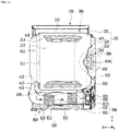
- FIG. 3 shows an outer shape of a laundry treating apparatus according to the present disclosure.
- the laundry treating apparatus may include a cabinet 100 constituting an outer shape.
- the cabinet 100 may include a front panel 110 constituting a front face of the laundry treating apparatus, a top panel 150 constituting a top face thereof, and a side panel 140 constituting a side face thereof.
- the side panel 140 may include a first side panel 141 constituting a left side face.
- the front panel 110 may include an opening 111 communicating with an interior of the cabinet 100 and a door 130 pivotably coupled to the cabinet 100 to open and close the opening 111.
- the front panel 110 may be equipped with a manipulating panel 117.
- the manipulating panel 117 may include an input unit 118 that receives a control command from a user, and a display 119 that outputs information such as a control command selectable by the user.
- the control commands may include a drying course or a drying option that may perform a series of drying cycles.
- a control box (see FIG. 12 ) that controls internal components to execute the control commands input through the input unit 118 may be installed inside the cabinet 100.
- the control box may be connected to components inside the laundry treating apparatus to control the components to perform an input command.
- the input unit 118 includes a power supply request unit that requests a power supply of the laundry treating apparatus, a course input unit that enables a user to select a desired course among a plurality of courses, and an execution request unit that requests start of a course selected by the user.
- the display 119 may be constructed to include at least one of a display panel capable of outputting texts and figures, and a speaker capable of outputting a voice signal and sound.
- the laundry treating apparatus may include a water storage tank 120 constructed to separately store moisture generated in a process of drying the laundry.
- the water storage tank 120 may include a handle which the user may grip to withdraw the tank 120 from one side of the front panel 110 to an outside.
- the water storage tank 120 may be constructed to collect the condensate generated during a drying cycle.
- the user may withdraw the water storage tank 120 from the cabinet 100, remove the condensate therefrom, and put the tank 120 back into the cabinet 100.
- the laundry treating apparatus according to the present disclosure may be disposed in a place where a sewer or the like is not installed.
- the water storage tank 120 may be disposed on top of the door 130. Accordingly, when the user withdraws the water storage tank 120 from the front panel 110, the user may bend a waist in a relatively smaller amount, thereby increasing the user's convenience.
- FIG. 4 briefly shows an inside of a laundry treating apparatus according to the present disclosure.
- the laundry treating apparatus includes a drum 200 accommodated inside the cabinet 100 to accommodate the laundry, a driver for rotating the drum 200, and a heat exchanger 900 constructed to supply hot air to the drum 200, and a base 800 having an air circulating channel 820.
- the air circulating channel 820 is communicating with the drum 200. Air discharged from the drum 200 may be supplied to the air circulating channel 820. Further, the air discharged from the air circulating channel 820 may be supplied to the drum 200 again.
- the driver may include a motor 500 that provides power to rotate the drum 200.
- the driver may be in direct connection with the drum 200 to rotate the drum 200.
- the driver may be embodied as a DD (Direct Drive) type driver. Accordingly, the driver may control a rotation direction of the drum 200 or a rotation speed of the drum 200 by directly rotating the drum 200 while the driver is free of a belt and a pulley.
- DD Direct Drive
- the motor 500 may rotate at high RPM.
- the laundry inside the drum 200 may rotate at a much higher RPM than RPM at which it may rotate while being coupled to an inner wall of the drum 200.
- the driver of the laundry treating apparatus may further include a speed reducer 600 that may reduce the RPM to increase the torque while taking advantage of a maximum output of the motor 500.
- the driver may include a drum rotation shaft 6341 connected to the drum 200 to rotate the drum 200.
- the drum 200 may be formed in a cylindrical shape to accommodate the laundry therein. Further, unlike the drum used for washing, water does not need to be put inside the drum 200 used only for drying, and liquid water condensed inside the drum 200 does not need to be discharged out of the drum 200. Therefore, through-holes defined in a circumferential face of the drum 200 may be omitted. That is, the drum 200 used only for drying may be different from the drum 200 used for washing.
- the drum 200 may be formed in an integral cylindrical shape, or may be manufactured in a structure in which a drum body 210 including a circumferential face and a drum rear face 220 constituting a rear face are coupled to each other.
- a laundry inlet 211 through which laundry enters and exits may be defined in a front face of the drum body 210.
- the driver that rotates the drum may be connected to the drum rear face 220.
- the drum body 210 and the drum rear face 220 may be coupled to each other via a fastener such as a bolt.
- the disclosure is not limited thereto. As long as the drum body 210 and the drum rear face 220 are coupled to each other while both rotate together, they may be coupled to each other using various methods.
- the drum body 210 may have a lift 213 for lifting the laundry up so that the laundry accommodated therein may be mixed with each other under the rotation.
- the laundry accommodated therein may repeatedly rise up and fall due to the lift 213.
- the laundry accommodated inside the drum 200 may be in contact with hot air while the laundry repeatedly rise up and fall. Therefore, the drying efficiency increases, and the drying time is shortened.
- a reinforcing bead 212 may be formed on a circumferential face of the drum body 210.
- the reinforcing bead 212 may be constructed to be recessed into or protrude from the circumferential face of the drum 200.
- the reinforcing bead may include a plurality of beads which may be constructed to be spaced apart from each other. The reinforcing beads may form a certain pattern and may be recessed into or protrude from the circumferential face.
- Rigidity of the drum body 210 may increase due to the reinforcing bead 212. Accordingly, even when a large amount of laundry is accommodated in the drum body 210 or a sudden rotation force is transmitted via the driver, the drum body 210 may be prevented from being distorted. Further, when the reinforcing bead 212 is provided, a spacing between the laundry and an inner circumferential face of the drum body may increase, compared to a case where the circumferential face of the drum body 210 is a flat face, so that the hot air supplied to the drum 200 is more effectively introduced between the laundry and the drum 200. Durability of the drum increases due to the reinforcing bead, and the drying efficiency of the laundry treating apparatus increases due to the bead.
- the driver may be fixed to a tub that accommodates the drum 200, and the drum 200 may be coupled to the driver and supported on the tub.
- a laundry treating apparatus according to the present disclosure may be constructed to intensively perform a drying cycle, a tub fixed to the cabinet 100 to accommodate the drum 200 is omitted.
- the laundry treating apparatus may further include a support 400 constructed to fix or support the drum 200 or the driver inside the cabinet 100.
- the support 400 may include a front plate 410 disposed in front of the drum 200 and a rear plate 420 disposed in rear of the drum 200.
- the front plate 410 and the rear plate 420 may have a plate shape and may be disposed to respectively face front and rear faces of the drum 200.
- a distance between the front plate 410 and the rear plate 420 may be set to be equal to a length of the drum 200 or be larger than the length of the drum 200.
- the front plate 410 and the rear plate 420 may be fixedly supported on the bottom face of the cabinet 100 or the base 800.
- the front plate 410 may be disposed between the front panel constituting the front face of the cabinet and the drum 200. Further, the front plate 410 may have an inlet-communication hole 412 communicating with the laundry inlet 211. Because the front plate 410 has the inlet-communication hole 412, the front face of the drum 200 is supported thereon, laundry may be put into or taken out from the drum 200.
- the front plate 410 may include a duct connector 416 disposed below the inlet-communication hole 412.
- the duct connector 416 may constitute a lower portion of the front plate 410.
- the front plate 410 may include a duct communication hole 417 extending through the duct connector 416.
- the duct communication hole 417 may have a hollow shape to guide the air discharged through the laundry inlet 211 of the drum to a bottom of the drum 200. Further, the air discharged through the laundry inlet 211 may be guided to the air circulating channel 820 positioned under the drum 200.
- a filter (not shown) may be installed in the duct communication hole 417 to filter foreign substances such as large lint or large particles generated from the laundry.
- the filter filters the air discharged from the drum 200 to prevent foreign substances from accumulating inside the laundry treating apparatus, and to prevent foreign substances from accumulating and thus interfering with circulation of the air.
- the driver is preferably installed on the rear plate 420 rather than the front plate 410.
- the driver may be constructed to be supported and mounted on the rear plate 420. This allows the driver to rotate the drum 200 while the position of the driver is stably fixed due to the rear plate 420.
- At least one of the front plate 410 and the rear plate 420 may support the drum 200 such that the drum may rotate. At least one of the front plate 410 and the rear plate 420 may accommodate a front or rear end of the drum 200 such that the drum may rotate.
- a front portion of the drum 200 may be rotatably supported on the front plate 410, and a rear portion of the drum 200 may be spaced apart from the rear plate 420 and may be connected to the motor 500 mounted on the rear plate 420 and thus may be indirectly supported on the rear plate 420. In this way, an area where the drum 200 contacts or rubs against the support 400 may be minimized and unnecessary noise or vibration may be prevented from occurring.
- the drum 200 may be constructed to be rotatably supported on both the front plate 410 and the rear plate 420.
- One or more support wheels 415 supporting the front portion of the drum 200 may be disposed at a lower portion of the front plate 410.
- the support wheel 415 may be rotatably disposed on a rear face of the front plate 410.
- the support wheel 415 may be rotated while in contact with a lower portion of the drum 200.
- the drum 200 When the drum 200 is rotated by the driver, the drum 200 may be supported on the drum rotation shaft 6341 connected to the rear portion of the drum.
- a load imposed to the drum rotation shaft 6341 due to the laundry may increase. Therefore, there is a risk of the drum rotation shaft 6341 being bent by the load.
- the load on the drum rotation shaft 6341 may be reduced. This may prevent the drum rotation shaft 6341 from being bent and prevent noise from being generated due to the vibration.
- the support wheels 415 may be disposed at positions symmetrical to each other around a center of rotation of the drum 200 so as to support the load of the drum 200.
- the support wheels 415 may be preferably disposed at left and right sides of the lower portion of the drum 200 to support the drum 200 thereon.
- the present disclosure is not limited thereto, and a larger number of support wheels 415 may be included according to an operating environment of the drum 200.
- the air circulating channel 820 disposed in the base 800 may circulate the air inside the drum 200 such that the air is input back into the drum 200.
- the air circulating channel 820 may include an inflow duct 821 into which the air discharged from the drum 200 flows, an air discharge duct 823 that supplies the air to the drum 200, and an air flow duct 822 connecting the inflow duct 821 and the air discharge duct 823 to each other.
- the air flow duct 822 When air is discharged from the front face of the drum 200, the air flow duct 822 may be located at a front side of the air circulating channel 820.
- the air discharge duct 823 may be located at a rear side of the air circulating channel 820.
- the air discharge duct 823 may further include a blower 8231 that discharges air out of the air circulating channel 820.
- the blower 8231 may be disposed at the rear side of the air discharge duct 823. Air exhausted through the blower 8231 may flow to the drum 200.
- a duct cover 830 may be coupled to a top of the air circulating channel 820, so that an open top face of the air circulating channel 820 may be partially shielded therewith.
- the duct cover 830 may prevent air from leaking out of the air circulating channel 820.
- the duct cover 830 may constitute one face of a channel through which air is circulated.
- a heat exchanger 900 disposed in the base 800 may include a first heat exchanger 910 disposed inside the air circulating channel 820 to cool the air, and a second heat exchanger 920 disposed inside the air circulating channel 820 to heat the air cooled in the first heat exchanger 910.
- the first heat exchanger 910 dehumidifies the air discharged from the drum 200, and the second heat exchanger 920 may heat the dehumidified air.
- the heated air is supplied to the drum 200 again to dry the laundry accommodated in the drum 200.
- Each of the first heat exchanger 910 and the second heat exchanger 920 may be embodied as a heat exchanger through which refrigerant flows.
- the first heat exchanger 910 may be embodied as an evaporator
- the second heat exchanger 920 may be embodied as a condenser.
- the refrigerant flowing along the first heat exchanger 910 and the second heat exchanger 920 may exchange heat with air discharged from the drum 200.
- the heat exchanger 900 may include an air circulating channel fan 950 that is installed in the air circulating channel 820 to generate air flow inside the air circulating channel 820. Further, the heat exchanger 900 may further include an air circulating channel fan motor 951 that rotates the air circulating channel fan 950. The air circulating channel fan 950 may be rotated upon receiving rotation power from the air circulating channel fan motor 951. When the air circulating channel fan 950 operates, the air dehumidified by the first heat exchanger 910 and then heated by the second heat exchanger 920 may flow to the rear portion of the drum 200.
- the air circulating channel fan 950 may be installed in one of the inflow duct 821, the air flow duct 822, and the air discharge duct 823. Because the air circulating channel fan 950 may be constructed to rotate, noise may be generated when the air circulating channel fan 950 operates. Therefore, it is preferable that the air circulating channel fan 950 may be disposed in rear of the air circulating channel 820.
- the air circulating channel fan 950 may be installed at the blower 8231. Further, the air circulating channel fan motor 951 may be located in rear of the blower 8231. When the air circulating channel fan 950 is rotated by the air circulating channel fan motor 951, air inside the air circulating channel 820 may be discharged out of the air circulating channel 820 via the blower 8231.
- the air circulating channel 820 and the heat exchanger 900 may be preferably disposed below the drum 200.
- the rear plate 420 may be disposed in rear of the drum 200 to guide the air discharged from the air circulating channel 820 to the drum 200.
- the rear plate 420 may be constructed to be spaced apart from the drum rear face 220.
- the air circulating channel 820 may receive air inside the drum 200 through the front plate 410 and supply air to the drum 200 through the rear plate 420. Air discharged from the air circulating channel 820 may be guided to the drum 200 through the rear plate 420.
- the base 800 may further include a connector 850 that guides the air discharged from the air circulating channel 820 to the rear plate 420.
- the connector 850 may guide the exhaust air to spread evenly throughout the rear plate 420.
- the connector 850 may be installed at the blower 8231. That is, the connector 850 may guide the air discharged from the blower 8231 to the rear plate 420. The hot air supplied to the rear plate 420 may flow into the drum 200 through the drum rear face 220.
- the drum 200 of the laundry treating apparatus according to the present disclosure may be rotated while being directly connected to the driver positioned in rear of the drum 200, rather than being indirectly rotated while being coupled to a belt. Therefore, unlike a drum of a conventional dryer that has a cylindrical shape in which front and rear faces are open, a rear face of the drum of the laundry treating apparatus according to the present disclosure may be shielded and may be directly coupled to the driver.
- the drum 200 may include the drum body 210 having a cylindrical shape to accommodate laundry and the drum rear face 220 coupled to the rear portion of the drum body 210 to define a rear face of the drum.
- the drum rear face 220 may be constructed to shield the rear face of the drum body 210, and provide a coupling face for direct engagement with the driver. That is, the drum rear face 220 may be connected to the driver and receive the rotation power to rotate an entirety of the drum 200. As a result, the front face of the drum body 210 may have the laundry inlet 211 into which laundry is put, and the rear face thereof may be shielded with the drum rear face 220.
- the drum rear face 220 may be equipped with a bushing 300 connecting the driver and the drum rear face 220 to each other.
- the bushing 300 may be disposed at the drum rear face 220 to define a center of rotation of the drum 200.
- the bushing 300 may be formed integrally with the drum rear face 220, or may be made of a material with greater rigidity and durability than that of the drum rear face 220 in order to be firmly coupled to the rotation shaft that transmits power.
- the bushing 300 may be seated on and coupled to the drum rear face 220 so as to be coaxial with the center of rotation of the drum rear face 220.
- the drum rear face 220 may include a circumferential portion 221 coupled to an outer circumferential face of the drum body 210, and a mount plate 222 that may be disposed inwardly of the circumferential portion 221 and may be coupled to the driver.
- the bushing 300 may be seated on the mount plate 222 and may be coupled thereto.
- the rotation shaft that rotates the drum may be coupled to the mount plate 222 via the bushing 300, and thus may be more firmly coupled thereto. Further, this may prevent deformation of the drum rear face 220 from occurring.
- the drum rear face 220 may include an intake hole 224 extending through a portion between the circumferential portion 221 and the mount plate 222, and aircommunicating in a front and rear direction of the drum rear face 220.
- the hot air supplied through the air circulating channel 820 may be introduced into the drum body 210 through the intake hole 224.
- the intake hole 224 may be embodied as a plurality of holes extending through the drum rear face 220 or as a mesh.
- the driver that rotates the drum 200 may be located in rear of the rear plate 420.
- the driver may include a motor 500 that generates rotation power and a speed reducer 600 that reduces the rotation force of the motor 500 and transmits the reduced force to the drum 200.
- the motor 500 may be disposed in rear of the rear plate 420.
- the motor 500 may be coupled to the rear face of the rear plate 420 via the speed reducer 600.
- the speed reducer 600 may be fixed to the rear face of the rear plate 420, and the motor 500 may be coupled to the rear face of the speed reducer 600. That is, the rear plate 420 may provide a support face on which the speed reducer 600 or the motor 500 is supported. However, the present disclosure is not limited thereto, and the motor 500 may be coupled to the rear plate 420.
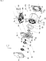
- FIG. 5 is an exploded perspective view showing internal components constituting the laundry treating apparatus in a separated state from each other.
- the laundry treating apparatus may include the drum 200 for accommodating the laundry, the front plate 410 for supporting the front face of the drum, the rear plate 420 located in rear of the drum, and the base 800 disposed below the drum to provide a space in which the air inside the drum is circulating or moisture contained in the air is condensed, and the motor 510, 520, and 540 which is located in rear of the drum and provides the rotation power to the drum, the speed reducer 600 to reduce the rotation speed of the motor and deliver the rotation power to the drum, and a rear cover 430 that may be coupled to the rear plate 420 to prevent the motor from being exposed to the outside.
- the base 800 may include the air circulating channel 820 which communicates with the drum 200, and receives the air from the drum or discharges the air to the drum.
- the front plate 410 may include a front panel 411 constituting a front face thereof, and the inlet-communication hole 412 that is formed to extend through the front panel 411 and communicates with the drum 200.
- the front plate 410 may have a front gasket 413 which may be disposed on the rear face of the front panel 411 and may be constructed to surround an radially outer side of the inlet-communication hole 412 and may accommodate a portion of the drum body 210.
- the front gasket 413 may support the drum body 210 such that the drum body may rotate, and may be in contact with the outer circumferential face or an inner circumferential face of the laundry inlet 211.
- the front gasket 413 may prevent the hot air inside the drum 200 from leaking into a space between the drum body 210 and the front plate 410.
- the front gasket 413 may be made of a plastic resin or an elastic body.
- a separate sealing member may be additionally coupled to the front gasket 413 to prevent laundry or the hot air from escaping from the drum body 210 to the front plate 410.
- the front plate 410 may include a duct communication hole 417 extending through an inner circumferential face of the inlet-communication hole 412. Further, the front plate 410 may include a duct connector 416 extending downwardly of the duct communication hole 417 to define a channel communicating the drum body 210 and the air circulating channel 820 to each other.
- the duct connector 416 may communicate with the drum body 210 through the duct communication hole 417, and the air discharged from the drum body 210 may flow into the duct connector 416 through the duct communication hole 417 and may be guided to the air circulating channel 820. Because the air discharged from the drum body 210 is guided to the air circulating channel 820 via the duct connector 416, this may prevent the air inside the drum from leaking out.
- a filter member (not shown) that filters foreign substances or lint from the air discharged from the drum 200 and prevents foreign substances from entering the air circulating channel 820 may be installed in the duct connector 416.
- the support wheels 415 supporting the lower portion of the drum 200 and being rotatably installed on the rear face of the front panel 411 may be installed on the front plate 410.
- the support wheel 415 supports the front face of the drum 200 and thus prevents the rotation shaft connected to the drum from being bent.
- the front plate 410 may have a water storage tank support hole 414 which may be constructed to extend through the front panel 411, and which the water storage tank 120 (see FIG. 1 ) in which the condensate generated in the drying process is stored may be withdrawn through or supported on.
- the water storage tank support hole 414 may be disposed a top level, the user does not have to bend his back when withdrawing the water storage tank, so that the user's convenience increases.
- the drum 200 for accommodating the laundry therein may include the drum body 210 having the laundry inlet 211 defined in a front portion thereof through which the laundry is input or output, and the drum rear face 220 constituting a rear face thereof.
- the drum rear face 220 may include the circumferential portion 221 connected to the drum body 210, the intake hole 224 defined inwardly of the circumferential portion 221 and extending through the drum rear face 220, and the mount plate 222 disposed at the center of rotation of the drum rear face 220, and coupled to the rotation shaft. Air may be introduced to the rear face of the drum through the intake hole 224.
- the drum rear face 220 may further include a reinforcing rib 225 extending from the circumferential portion 221 toward the center of rotation.
- the reinforcing rib 225 may extend while bypassing the intake hole 224.
- the reinforcing rib 225 has the effect of preventing the rigidity of the drum rear face 220 from being reduced due to the intake hole 224.
- the reinforcing rib 225 may be constructed to extend radially from the outer circumferential face of the mount plate 222 toward an inner circumferential face of the circumferential portion 221.
- the drum rear face 220 may further include a circumferential rib 227 extending in the circumferential direction of the drum rear face 220 to connect the reinforcing ribs 225 to each other.
- the intake holes 224 may be respectively disposed between adjacent ones of the reinforcing rib 225, the circumferential rib 227, and the circumferential portion 221.
- the reinforcing rib 225 and the circumferential rib 227 have the effect of preventing the drum rear face 220 from being deformed upon receiving the rotation force from the motor 500.
- the inflow duct 821 may communicate with the duct communication hole 417 of the front plate 410 to communicate with a channel installed inside the front plate 410.
- the air flow duct 822 may extend from a distal end of the inflow duct 821 toward the rear face of the drum 200, and the air discharge duct 823 may be disposed at a distal end of the air flow duct 822 to direct the air to the drum 200.
- the blower 8231 may be located downstream of the air discharge duct 823, and the blower 8231 may provide a space where the air circulating channel fan is installed. When the circulation fan channel fan operates, the air introduced into the inflow duct 821 may be discharged upwardly of the blower 8231.
- the base 800 may be equipped with the heat exchanger 900 that may cool and heat the air circulating inside the drum 200.
- the heat exchanger 900 may include a compressor 930 connected to the first heat exchanger and the second heat exchanger to supply compressed refrigerant.
- the compressor 930 may be constructed so as not to directly exchange heat with the circulating air, and thus may be located out of the air circulating channel 820.
- the heat exchanger may include the air circulating channel fan motor 951 supported on a rear face of the blower 8231 to rotate the air circulating channel fan.
- the air circulating channel fan motor 951 may be coupled to the rear face of the blower 8231.
- the laundry treating apparatus may further include the connector 850 which may be coupled to the air circulating channel 820 for guiding the hot air discharged from the air circulating channel 820 to the rear portion of the drum 200 or the rear plate 420.
- the connector 850 may be disposed on top of the air discharge duct 823 and be constructed to guide the hot air heated through the second heat exchanger 920 upwards beyond the air discharge duct 823. Further, the connector 850 may be coupled to an opening disposed above the blower 8231.
- the connector 850 may be constructed to have a channel defined therein.
- the connector 850 may be constructed to evenly guide the flow of air generated by the air circulating channel fan to the rear plate 420. That is, the connector 850 may be constructed so that an area of the channel therein increases as a distance thereof from the blower 8231 increases.
- the rear plate 420 may be coupled to the base 800 or supported on the base 800 and be positioned in rear of the drum 200.
- the rear plate 420 may be constructed to include the rear panel 421 positioned to face toward the front plate 410, and a duct portion 423 recessed in the rear panel 421 to define a channel through which air flows and to guide the air discharged from the air circulating channel 820 to the drum.
- the rear plate 420 may include a mount 425 to or on which the driver is coupled or supported.
- the mount 425 may be constructed to extend through the rear panel 421 and disposed on an inner circumferential face of the duct portion 423.
- the mount 425 may be constructed to be spaced apart from an inner circumferential face of the duct portion 423 inwardly in a radial direction.
- the driver may mean a combination of the speed reducer 600 and the motor 500 as described above.
- the driver may mean only the motor 500. That is, a component that generates power and transmits the rotation power to the drum may be referred to as a driver.
- the driver may be mounted on the mount 425.
- the mount 425 may support the driver's load.
- the driver may be connected to the drum 200 while supported on the mount 425.
- the duct portion 423 may be constructed to receive a portion of the drum rear face 220.
- the duct portion 423 may have the channel defined therein through which air flows together with the drum rear face 220.
- the driver may be installed on the mount 425 so as not to interfere with the duct portion 423.
- the driver may be radially inwardly spaced away from an inner circumferential face of the duct portion 423.
- the driver may be installed on the mount 425, while a rear portion thereof may be exposed to the outside so that it may be cooled by external air.
- the driver may include the motor 500 that provides power to rotate the drum 200.
- the motor 500 may include a stator 510 that generates a rotating magnetic field, and a rotor 520 that may be constructed to rotate by the stator 510.
- the rotor 520 accommodates the stator 510 and may be equipped with an outer rotor type constructed to rotate along the circumference of the stator 510.
- the rotor 520 may be coupled to a drive shaft and may be directly connected to the drum 200 through the stator 510 and the mount 425. In this case, the rotor 520 may directly transmit the power to rotate the drum 200.
- the rotor 520 may be coupled to the drive shaft via a washer 540.
- the washer 540 may perform a function of connecting the drive shaft and the rotor 520 to each other. Because a contact area between the rotor 520 and the drive shaft may increase due to the washer 540, the rotation of the rotor 520 may be transmitted more effectively.
- the speed reducer 600 may be constructed to connect the motor 500 and the drum 200 to each other.
- the speed reducer 600 may convert the power of the motor 500 to rotate the drum 200.
- the speed reducer 600 may be disposed between the motor 500 and the drum 200 to receive the power of the motor 500, convert the same, and transmit the same to the drum 200.
- the speed reducer 600 may be constructed to convert the RPM of the rotor to a small RPM but increase a torque value thereof and transfer the converted RPM to the drum 200.
- the speed reducer 600 may be coupled to the rotor 520 and the drive shaft that rotates with the rotor 520.
- the speed reducer 600 may include a gear assembly that may be engaged with the drive shaft and rotates therewith to reduce the RPM of the drive shaft but increase the torque thereof.
- the gear assembly may be coupled to the drum 200 and may be connected to the drum rotation shaft to rotate the drum.
- the drum rotation shaft rotates at a slower RPM than that of the drive shaft, but with the increased torque.
- this speed reducer 600 depends on whether the drive shaft and the drum rotation shaft may be kept coaxial with each other. That is, when the drive shaft and the drum rotation shaft are misaligned with each other, there is a risk that coupling between the parts constituting the gear assembly inside the speed reducer 600 and at least one of the drive shaft and the drum rotation shaft may loosen or may be disengaged. Therefore, the power of the drive shaft may not be properly transmitted to the drum rotation shaft, or the drive shaft may rotate in vain.
- the gears inside the speed reducer 600 may be misaligned with each other and collide with each other, resulting in unnecessary vibration or noise.
- speed reducer 600 may completely deviate from its correct position or be damaged when an angle by which the drive shaft and the drum rotation shaft are misaligned with each other increases even temporarily.
- the speed reducer 600 and the motor 500 are preferably fixed to a support that maintains its original state without deformation even when an external force is applied thereto.
- the tub accommodating the drum may be first fixed to the cabinet, and then the motor and the speed reducer may be second fixed to a bearing housing made of a rigid body built into the tub by injection molding.
- This allows the speed reducer and the driver to tilt or vibrate together with the bearing housing or the fixing steel plate, even when significant vibrations occur in the tub.
- the speed reducer and the driver themselves may always maintain a combined state therewith, and the drive shaft and the rotation shaft may be kept coaxial.
- the laundry treating apparatus is embodied as a dryer, the tub fixed inside the cabinet is omitted.
- the rear panel of the cabinet is made of a relatively thin plate, even when the stator 510 is fixed thereto, the rear panel may easily vibrate or be bent due to a repulsive force when the rotor 520 rotates.
- the rotation centers of the speed reducer 600 and the motor 500 which are in combination with the drum 200 may be misaligned with each other.
- the real panel may not support both the speed reducer 600 and the motor 500.
- the speed reducer 600 and the motor 500 are coupled to the rear panel and are arranged side by side, a rotational moment may be generated due to a total length and weight of the speed reducer 600 and the motor 500, such that the speed reducer 600 sags downwards.
- the drum rotation shaft itself coupled to the drum may be misaligned with the speed reducer 600.
- the drum rotation shaft and the drive shaft may not be maintained at the coaxial state.
- a configuration may be considered that the stator 510 may be coupled to the rear plate 420 to support the motor 500.
- the drum rotation shaft may be distorted according to the displacement of the laundry whenever the drum 200 rotates.
- the stator 510 may be separated from the drum 200 and fixed to the rear plate 420, so that the drum rotation shaft may vibrate at a different dimension or tilt at a different angle than the stator 510 may do. Therefore, the coaxiality of the drum rotation shaft and the drive shaft may not be maintained.
- the drum 200 may be supported on the front plate 410 and the rear plate 420 so that an installed position thereof may be fixed to a certain degree. Therefore, the position of the drum rotation shaft coupled to the drum 200 may be fixed to a certain degree. Therefore, even when vibration occurs in the drum 200, the vibration may be buffered by at least one of the front plate 410 or the rear plate 420.
- the vibration amplitude of the drum rotation shaft is larger than the vibration amplitude of the motor 500 and the rear plate 420.
- the drive shaft and the drum rotation shaft cannot be maintained in a coaxial relationship with each other.
- the motor 500 may be fixedly coupled to the speed reducer 600.
- the speed reducer 600 itself may serve as a reference point of an entirety of the driver.
- the speed reducer 600 may serve as a reference of the overall vibration amplitude and tilting angle of the driver.
- the motor 500 is not fixed to other components of the laundry treating apparatus, but is fixed only to the speed reducer 600. Thus, when vibration is transmitted to the driver or external force is transmitted thereto, the motor 500 may always tilt or vibrate simultaneously together with the speed reducer 600 when the speed reducer 600 tilts or vibrates.
- the speed reducer 600 and the motor 500 may constitute one vibration system, and the speed reducer 600 and the motor 500 may be maintained in a fixed state with each other while not performing relative motion with respect to each other.
- the stator 510 of the motor 500 may be directly coupled to the speed reducer 600 and fixed thereto. In this way, the installed position of the drive shaft 530 relative to the speed reducer 600 may not be changed. A center of the drive shaft 530 and a center of the speed reducer 600 may coincide with each other, and thus the drive shaft 530 may rotate in the coaxial state with the center of the speed reducer 600.
- a first axis M1 may mean an imaginary line extending in a front-rear direction along the center of rotation of the drum 200. That is, the first axis M1 may extend in parallel to an X axis.
- Each of a second axis M2 and a third axis M3 may refer to an imaginary line extending in a left and right direction of the laundry treating apparatus. That is, each of the second axis M2 and the third axis M3 may be orthogonal to an XZ plane and parallel to an Y axis.
- the first axis M1 and the second axis M2 may intersect each other at the speed reducer 600. Further, the first axis M1 and the third axis M3 may intersect with each other at the mount 425.
- the speed reducer 600 and the motor 500 may be designed to be arranged along the first axis M1 parallel to a ground when there is no load on the drum 200 or when the motor 500 is not running.
- the motor 500 may be coupled to the speed reducer 600, and thus may vibrate or tilt together with the speed reducer 600.
- the motor 500 and the speed reducer 600 may be arranged side by side along the second axis M2.
- the drive shaft and the drum rotation shaft may be arranged side by side along the second axis M2.
- the motor 500 may move integrally with the speed reducer 600, and thus the drive shaft and the drum rotation shaft may be maintained in a coaxial state with each other.
- the speed reducer 600 may be fixedly coupled to the rear plate 420.
- the speed reducer 600 will tilt or vibrate while being coupled to the rear plate 420, so that the rear plate 420 plays the role of the center of the vibration system including the speed reducer 600, the motor 500, and the drum 200.
- the motor 500 may be not directly coupled to the rear plate 420, but may be only coupled to the speed reducer 600 and fixed thereto.
- the speed reducer 600 and the motor 500 and the drum 200 may be arranged side by side along the first axis M1. However, the vibration of the drum 200 or the motor 500 causes the speed reducer 600 to be inclined in parallel to the third axis M3.
- the third axis M3 may extend through the speed reducer 600 coupled to the rear plate 420. In this connection, the speed reducer 600 and the motor 500 are coupled to each other, so that the motor 500 may be tilted in parallel to the third axis M3, just like the speed reducer 600.
- the motor 500 and the drum 200 may be coupled to the speed reducer 600, so that the motor 500 and the drum 200 may be tilted in parallel manner with respect to the speed reducer 600 or vibrate at the same time with the vibration of the speed reducer.
- coaxiality and the coincidence does not mean physically perfect coaxiality and coincidence, but may allow an error range acceptable in mechanical engineering or as recognized as coaxiality or coincidence by a person skilled in the art.
- a state in which the drive shaft 530 and the drum rotation shaft 6341 are misaligned with each other by a range within 5 degrees may be defined as being coaxial or coincident.
- the angle value is only an example, and the allowable error in design may be changed.
- the drive shaft 530 rotates relative to the speed reducer 600 but is fixed thereto to prevent tilting of the drive shaft 530, and the stator 510 is fixed to the speed reducer 600, a distance between the stator 510 and the rotor 520 may always be maintained to be constant. As a result, the collision between the stator 510 and the rotor 520 may be prevented. The noise or vibration that may occur due to the change of the rotation center as the rotor 520 rotates the stator 510 may be fundamentally blocked.
- the drum rotation shaft 6341 may be constructed to extend from the inside of the speed reducer 600 toward the drum 200, and may vibrate together with the speed reducer 600 and tilt tougher with the speed reducer 600. That is, the drum rotation shaft 6341 may be only constructed to be rotatably coupled to the speed reducer 600, but the installed position thereof may be fixed. As a result, the drum rotation shaft 6341 and the drive shaft 530 may always be arranged side by side and coaxial with each other. In other words, the center of the drum rotation shaft 6341 and the center of the drive shaft 530 may be maintained in a coinciding manner with each other.
- a sealing portion 450 may be disposed between the drum rear face 220 and the rear plate 420.
- the sealing portion 450 may seal between the drum rear face 220 and the rear plate 420 so that the air introduced into the duct portion 423 of the rear plate 420 does not flow out thereof and flows into the intake hole 224.
- the sealing portion 450 may be disposed on each of an outer side face and an inner side face of the duct portion 423.
- a first sealing 451 may be disposed at a radially outer side of the duct portion 423, and a second sealing 452 may be disposed at a radially inner side.
- the first sealing 451 may prevent hot air between the drum rear face 220 and the duct portion 423 from leaking radially outwardly.
- the second sealing 452 may prevent hot air between the drum rear face 220 and the duct portion 423 from leaking radially inwardly.
- the sealing portions 450 may be disposed at the radially outer and inner sides of the intake hole 224, respectively.
- the first sealing 451 may be disposed at the radially outer side of the intake hole 224, and the second sealing 452 may be disposed at the radially inner side of the intake hole 224.
- the sealing portion 450 is preferably constructed to be in contact with both the drum rear face 220 and the rear plate 420 in order to prevent the hot air from leaking out. Because the drum 200 rotates during the operation of the laundry treating apparatus, continuous friction from the drum rear face 220 is applied to the sealing portion 450. Therefore, the sealing portion 450 may be preferably made of a material that may seal between the drum rear face 220 and the duct portion 423 without deterioration in performance even due to the frictional force and frictional heat generated according to rotation.
- the motor 500 or the speed reducer 600 may be coupled to the rear face of the rear plate 420, and the rear plate 420 may be made of a thin sheet metal, so that the rear plate 420 may be bent or deformed due to the load transmitted to the speed reducer 600 via the speed reducer 600 and the drum 200. That is, the rigidity of the rear plate 420 needs to be secured to install the speed reducer 600 and the motor 500 thereon.
- the rear plate 420 may further include a bracket 700 to reinforce coupling rigidity.
- the rear plate 420 may additionally be coupled to the bracket 700 and the speed reducer 600 and the motor 500 may be coupled to the rear plate 420 via the bracket 700.
- the speed reducer 600 may be coupled simultaneously to the bracket 700 and the rear plate 420.
- the fastener may simultaneously extend through and couple the speed reducer 600, the rear plate 420, and the bracket 700 to each other.
- the rear plate 420 may be coupled to the bracket 700 to ensure rigidity thereof.
- the speed reducer 600, the motor 500, etc. may be coupled to the rear plate 420 with the secured rigidity.
- the fastening may be made in such a way that the speed reducer 600 is first coupled to the bracket 700 and the bracket 700 is then coupled to the rear plate 420. That is, the speed reducer may not be directly coupled to the rear plate 420, but may be fixed to the rear plate 420 via the bracket 700.
- the motor 500 or the speed reducer 600 may be coupled to the rear face of the rear plate 420
- the motor 500 and the speed reducer 600 may be exposed to the outside. Therefore, it is necessary to prevent the motor 500 from being exposed to the outside while being coupled to the rear face of the rear plate 420.
- the duct portion 423 may be heated by the hot air. Therefore, it may be necessary to thermally insulate the rear face of the duct portion 423.
- the rear cover 430 may be coupled to the rear face of the rear plate 420 to prevent the duct portion 423 and the motor 500 or the speed reducer 600 from being exposed to the outside.
- the rear cover 430 may be spaced apart from the duct portion 423 and the driver.
- the rear cover 430 has the effect of preventing the motor 500 from being damaged due to external interference, or preventing the drying efficiency from being lowered due to heat loss through the duct portion 423.
- FIG. 6 shows an outer shape of the speed reducer according to one embodiment of the present disclosure.
- the speed reducer 600 may include a speed reducer housing 610 and 620 constituting an outer shape thereof.
- the speed reducer housing may include a first housing 610 constructed to face toward the drum and a second housing 620 to face toward the motor.
- the speed reducer 600 may include a gearbox.
- the gearbox may be constructed to receive power from the motor and convert the motor's RPM to a small RPM but increase the torque value and transmit the converted rotation force to the drum.
- a significant portion of the gearbox may be housed inside the second housing 620, and the first housing 610 may be constructed to shield the inside of the speed reducer 600. In this way, an overall thickness of the speed reducer 600 may be reduced.
- the detailed configuration of the gearbox will be described later.
- the first housing 610 may include a first housing shielding body 611 constructed to shield the second housing 620 and a first housing shaft receiving portion 612 extending from the first housing shielding body 611 in a direction away from the second housing 620.
- the first housing shaft receiving portion 612 may receive the drum rotation shaft 6341 and may support the drum rotation shaft 6341 such that the drum rotation shaft 6341 may rotate.
- the first housing 610 may include a stator coupling portion 613 constructed to support the motor.
- the stator coupling portion 613 may extend from a circumferential face of the first housing shielding body 611 in a direction away from the first housing shaft receiving portion 612.
- the stator coupling portion 613 may include a stator fastening hole 615 to which the motor may be fastened.
- the stator fastening hole 615 may be recessed in the stator coupling portion 613.
- a separate fastener may be inserted into the stator fastening hole 615.
- the stator coupling portion 613 and the motor may be coupled to each other using the fastener.
- the first housing 610 may further include a coupling guide 614 to guide the coupling of the motor.
- the coupling guide 614 may extend from the circumferential face of the first housing shielding body 611 in a direction away from the first housing shaft receiving portion 612.
- the coupling guide 614 may extend from the first housing shielding body 611 so as to be connected to the stator coupling portion 613.
- the coupling guide 614 may guide a position of the stator 510 when the stator 510 may be coupled to the stator coupling portion 613.
- the assembility may be improved.
- the second housing 620 may house the gear assembly therein.
- the gearbox coupled to the speed reducer 600 may include a sun gear, a planetary gear orbiting the sun gear, and a ring gear that accommodates the planetary gear and allows the planetary gear to rotate.
- the second housing 620 may include a second housing coupling body 621 coupled to the first housing 610, a second housing shielding body 622 extending from the second housing coupling body 621 in a direction away from the first housing 610 and defining a space in which the gearbox is accommodated, and a second housing shaft receiving portion extending from an inner circumferential face of the second housing shielding body 622 in a direction away from the first housing 610 to support the drive shaft 530.
- a center of the first housing 610 and A center of the second housing 620 may be designed to be coaxial with each other.
- the drive shaft 530 and the drum rotation shaft 6341 are coaxial with each other, this is advantageous for power transmission. Accordingly, it is preferable that the first housing shaft receiving portion 612 rotatably supporting the drum rotation shaft 6341 and the second housing shaft receiving portion rotatably supporting the drive shaft 530 are coupled to each other so as be coaxial with each other.
- the drive shaft 530 may be inserted into the second housing 620 and rotatably supported within the second housing 620.
- the drive shaft 530 may be coupled to the washer 540 that rotatably supports the rotor 520.
- the washer 540 may include a receiving body 542 having a shaft support hole 543 defined in a center thereof for receiving the drive shaft 530, and a washer coupling body 541 extending radially from an outer circumferential face of the receiving body 542 to define a face to which the rotor is coupled.
- the shaft support hole 543 may be formed in a groove shape corresponding to a protrusion formed on an outer circumferential face of the drive shaft 530 such that the protrusion may be received in the groove.
- the washer 540 may include at least one washer coupling protrusion 5411 constructed to protrude from the washer coupling body 541 in a direction away from the speed reducer. Further, the washer 540 may include one or more washer coupling holes 5412 extending through the washer coupling body 541.
- the washer coupling protrusion 5411 may be coupled to a receiving groove formed in the rotor.
- a fastener passing through the rotor may be inserted into the washer coupling hole 5412 to couple the rotor and the washer 540 to each other.
- a plurality of washer coupling protrusions 5411 and a plurality of washer coupling holes 5412 may be alternately arranged along a circumferential direction and may be disposed on a surface of the washer coupling body 541.
- FIG. 7 is an enlarged cross-sectional view of the driver shown briefly in FIG. 2 in detail.
- the driver may include the motor 500 that generates rotation power and the speed reducer that reduces the rotation speed of the motor 500 and delivers the rotation power having the reduced speed to the drum.
- the speed reducer 600 may include the drum rotation shaft 6341 that rotates the drum.
- the motor 500 may include the stator 510 that generates a rotating magnetic field upon receiving external power and the rotor 520 that surrounds an outer circumferential face of the stator 510. Permanent magnets may be disposed on an inner circumferential face of the rotor 520.
- the permanent magnets located on an inner circumferential face of the rotor 520 may move in a specific direction via rotating magnetism generated by the stator 510, and the permanent magnet may be fixed to an inner circumferential face of the rotor 520. Therefore, the rotor 520 may be rotated under the rotating magnetic field of the stator 510.
- the drive shaft 530 that rotates together with the rotor 520 and transmits the rotation power of the rotor 520 may be coupled to a center of rotation of the rotor 520.
- the drive shaft 530 may be constructed to rotate together with the rotor 520.
- the drive shaft 530 may be coupled to the rotor 520 via the washer 540.
- the drive shaft 530 may be directly connected to the rotor 520.
- the rotor 520 may be coupled thereto more firmly and thus may transmit the rotation force of the rotor 520 more effectively. Further, this may prevent the load from being concentrated on the drive shaft 530, thereby increasing the durability of the drive shaft 530.
- the drive shaft 530 may be directly connected to the drum. However, the drive shaft 530 rotates at the same speed as that of the rotor 520, there may be cases where deceleration thereof is necessary. Thus, the drive shaft 530 may be connected to the speed reducer, and the speed reducer may be connected to the drum. That is, the speed reducer may decelerate the rotation of the drive shaft 530 to rotate the drum in the decelerated manner.
- the speed reducer 600 may include a first housing 610 and a second housing 620 constituting an outer shape, and the gearbox 630 for reducing the power of the drive shaft 530.
- the second housing 620 may provide a space to accommodate the gearbox 630 therein, and the first housing 610 may shield the accommodating space defined in the second housing 620.
- the second housing 620 may include a second housing coupling body 621 coupled to the first housing 610, a second housing shielding body 622 extending rearwards from an inner circumferential face of the second housing coupling body 621 to define the receiving space for receiving the gearbox 630, and a second housing shaft receiving portion 623 extending rearwardly from the second housing shielding body 622 and constructed to receive the drive shaft 530.
- the gearbox 630 may include the ring gear 633 installed along an inner circumferential face of the second housing shielding body 622.
- One or more planetary gear 632 meshed with the ring gear 633 may be disposed on an inner circumferential face of the ring gear 633.
- the planetary gear 632 may be meshed with the ring gear 633, and the sun gear 631 may rotate together with the drive shaft 530.
- the sun gear 631 may be constructed to rotate while being coupled to the drive shaft 530.
- the sun gear 631 may be embodied as a separate member from the drive shaft 530.
- the disclosure is not limited thereto, and the sun gear 631 may be formed integrally with the drive shaft 530.
- Each of the sun gear 631, the planetary gear 632 and the ring gear 633 may be embodied as a helical gear.
- noise may be reduced and power transmission efficiency may increase.
- the present disclosure is not limited thereto, and each of the sun gear 631, the planetary gear 632, and the ring gear 633 may be embodied as a spur gear.
- the gearbox 630 As the rotor rotates, the drive shaft 530 and the sun gear 631 connected to the drive shaft 530 rotate.
- the planetary gear 632 meshed with an outer circumferential face of the sun gear 631 may rotate while being disposed between the ring gear 633 and the sun gear 631.
- the planetary gear 632 may include a planetary gear shaft 6323 that is inserted into the center of rotation.
- the planetary gear shaft 6323 may rotatably support the planetary gear 632.
- the speed reducer may further include a first carrier 6342 and a second carrier 6343 supporting the planetary gear shaft 6323.
- a front face of the planetary gear shaft 6323 may be supported on the second carrier 6343, while a rear face thereof may be supported on the first carrier 6342.
- the drum rotation shaft 6341 may extend from the rotation center of the second carrier 6343 in a direction away from the motor.
- the drum rotation shaft 6341 may be embodied as a separate component from the second carrier 6343 and may be coupled thereto such that both rotate together. To the contrary, the drum rotation shaft 6341 may extend from the second carrier 6343 and be integrally formed with the second carrier 6343.
- the drum rotation shaft 6341 may be coupled to the drum to rotate the drum. As described above, the drum rotation shaft 6341 may be coupled to the drum via a connecting body such as a bushing, or may be directly coupled to the drum without a separate connecting body.
- the drum rotation shaft 6341 may be supported on the first housing 610.
- the first housing 610 may include a first housing shielding body 611 shielding the receiving space of the second housing 620, and a first housing shaft receiving portion 612 extending from the first housing shielding body 611 in a direction away from the second housing 620 to accommodate the drum rotation shaft 6341 therein.
- a first bearing 660 and a second bearing 670 may be press-fitted to an inner circumferential face of the first housing shaft receiving portion 612 to rotatably support the drum rotation shaft 6341.
- the first housing 610 and the second housing 620 may be coupled to each other via a speed reducer fastener 681. Further, the speed reducer fastener 681 passes through the first housing 610 and the second housing 620 at the same time and may couple both to each other. Further, the speed reducer fastener 681 passes through the first housing 610, the second housing 620 and the rear plate 420 simultaneously to couple the first housing 610 and the second housing 620 to each other and at the same time to fix the speed reducer 600 to the rear plate 420.
- the rear plate 420 may be made of a thin steel plate. Therefore, the rear plate 420 may not secure the rigidity thereof to support all of the speed reducer 600, the motor 500 connected to the speed reducer 600, and the drum 200 connected to the speed reducer 600. Therefore, the bracket 700 may be used to secure the rigidity of the rear plate 420 when coupling the speed reducer 600 to the rear plate 420.
- the bracket 700 may be made of a material with higher rigidity than that of the rear plate 420 and may be coupled to the front face or rear of the rear plate 420.
- the bracket 700 may be coupled to the front face of the rear plate 420 to secure the rigidity such that the speed reducer 600 may be coupled thereto, and the speed reducer 600 may be coupled to the rear plate 420 and the bracket 700 at the same time.
- a fastener such as a bolt may be used to couple the rear plate 420 to the bracket 700 and the speed reducer.
- the speed reducer fastener 681 that is used to couple the first housing 610 and the second housing 620 to each other may be used. That is, the speed reducer fastener 681 may extend through the second housing 620, the first housing, the rear plate 420 and the bracket 700 at the same time to couple all thereof to each other. Thus, a front face of the rear plate 420 may be supported on the bracket 700 and a rear face thereof may be supported on the first housing 610. Thus, when the speed reducer 600 may be coupled to the rear plate 420, the rigidity thereof may be secured.
- the present disclosure is not limited thereto. First, only the first housing 610 and the second housing 620 may be coupled to each other using the speed reducer fastener 681, and then the speed reducer 600 may be coupled to the rear plate 420 using a separate fastener.
- stator coupling portion 613 to which the motor 500 may be coupled may be formed at a radially outer side of the first housing 610.
- the stator coupling portion 613 may include a coupling groove formed by recessing which the stator coupling portion 613.
- the stator 510 may be directly coupled to the rear plate 420, or may be coupled to the stator coupling portion 613.
- the stator 510 may include a fixing rib 512 that may be disposed on an inner circumferential face thereof to support the stator.
- the fixing rib 512 may be coupled to the stator coupling portion 613.
- the fixing rib 512 and the stator coupling portion 613 may be coupled to each other via a stator coupling pin 617.
- the motor 500 may be coupled to the speed reducer 600 while being spaced apart from the rear plate 420, so that the motor 500 and the speed reducer 600 may constitute a single vibrating body. Therefore, even when external vibration is applied, the drive shaft 530 coupled to the rotor 520 and the drum rotation shaft 6341 connected to the speed reducer 600 may easily maintain the coaxial relationship with each other.
- the motor 500 may be coupled to the first housing 610 supporting the drum rotation shaft 6341, such that even when the axial direction of the drum rotation shaft 6341 tilts, an axial direction of the drive shaft 530 may tilt by the same degree via the first housing 610. That is, the motor 500 may move integrally with the speed reducer 600 so that the drum rotation shaft 6341 and the drive shaft 530 may be maintained in a coaxial relationship with each other even when the external force is applied thereto.
- the efficiency and reliability at which the power generated from the motor 500 is transmitted to the drum 200 may increase, and wear, decrease in power transmission efficiency and durability and reliability of the gearbox 630 as caused by the axial misalignment between the drum rotation shaft 6341 and the drive shaft 530 may be prevented.
- FIG. 8 shows the base and the rear plate according to one embodiment of the present disclosure.
- the rear plate 420 may be located in rear of the drum.
- the rear plate 420 may guide the hot air discharged from the air circulating channel 820 to the drum. That is, the rear plate 420 may be located in rear of the drum to define a channel so that the hot air is uniformly supplied to an entirety of the drum.
- the rear plate 420 may include the rear panel 421 facing toward the drum rear face, and the duct portion 423 that may be constructed to be recessed rearwardly in the rear panel 421 to define a channel.
- the duct portion 423 may be formed by pressing backwards the rear panel 421.
- the duct portion 423 may be constructed to receive a portion of the drum rear face.
- the duct portion 423 may include an air inlet 4233 positioned in rear of the air circulating channel and an air flow portion 4231 positioned in rear of the drum.
- the air flow portion 4231 may be constructed to receive a portion of the drum.
- the air flow portion 4231 may accommodate a portion of the drum, and may define a channel located in rear of the drum.
- the air flow portion 4231 may be formed in an annular shape so as to face toward the intake hole defined in the rear face of the drum.
- the air flow portion 4231 may be constructed to be recessed in the rear panel 421. That is, the air flow portion 4231 may be constructed so that a front face thereof is open, and may define a channel together with the rear face of the drum.
- the hot air flowing to the air flow portion 4231 may directly flow to the drum without passing through a separate component. Accordingly, this may prevent heat loss from occurring while hot air passes through the separate component. That is, there is an effect that may increase the drying efficiency by reducing the heat loss of the hot air.
- the rear plate 420 may include the mount 425 disposed at the radially inner side of the air flow portion 4231.
- the mount 425 may provide a location to which the speed reducer 600 or the motor 500 is coupled. That is, the rear plate 420 may include the mount 425 disposed at an inner side thereof, and the air flow portion 4231 formed in an annular shape and disposed at a radially outer side of the mount 425.
- the air flow portion 4231 may include an outer circumferential portion 4231a disposed outwardly of and surrounding an inner space in which hot air flows. Further, the air flow portion 4231 may include an inner circumferential portion 4231b disposed inward" ly of and surrounding the inner space in which hot air flows. That is, the outer circumferential portion 4231a may constitute an outer circumference of the air flow portion 4231, and the inner circumferential portion 4231b may constitute an inner circumference of the air flow portion 4231.
- the air flow portion 4231 may include a recessed face 4232 that forms a rear face of the channel through which the hot air flows.
- the recessed face 4232 may be constructed to connect the outer circumferential portion 4231a and the inner circumferential portion 4231b to each other. That is, a space in which the hot air discharged from the air circulating channel 820 flows may be defined by the inner circumferential portion 4231b, the outer circumferential portion 4231a, and the recessed face 4232.
- the recessed face 4232 prevents the hot air from leaking rearwardly and guides the hot air toward the drum. That is, the recessed face 4232 may mean a recessed face in the air flow portion 4231.
- the air inlet 4233 may be positioned to face toward the air circulating channel 820.
- the inlet may be positioned to face toward the blower 8231.
- the air inlet 4233 may be constructed to be recessed backwards in the rear panel 421 to prevent interference with the blower 8231.
- a top of the air inlet 4233 may be connected to the air flow portion 4231.
- the laundry treating apparatus may include the connector 850 connected to the blower 8231.
- the connector 850 may guide the hot air discharged from the blower 8231 to the air flow portion 4231.
- the connector 850 may have a channel defined therein to guide the hot air discharged from the blower 4231 to the air flow portion 4231. That is, the connector 850 may define the channel for connecting the blower 8231 and the air flow portion 4231 to each other.
- a cross-sectional area of the channel defined inside the connector 850 may be constructed to increase as the channel extends away from the blower 8231.
- the connector 850 may be positioned to face toward the air inlet 4233.
- the air inlet 4233 may be formed to be recessed backwards to prevent interference with the connector 850.
- a top of the connector 850 may be constructed to partition the air flow portion 4231 and the air inlet 4233 from each other. That is, the hot air discharged from the connector 850 may be introduced into the air flow portion 4231, but may be prevented from flowing into the air inlet 4233.
- the connector 850 may be constructed to evenly supply the hot air to the air flow portion 4231.
- the connector 850 may be constructed so that a width thereof increases as a distance thereof from the blower 8231 increases.
- the top of the connector 850 may be positioned along a circumferential extension line of the outer circumferential portion 4231a.
- the hot air discharged from the connector 850 may be supplied to an entirety of the air flow portion 4231 without flowing to the air inlet 4233.
- the connector 850 prevents the hot air from being concentrated on one side of the air flow portion 4231, so that the hot air may be evenly supplied to the inside of the drum. Therefore, there is an effect of increasing the drying efficiency of laundry.
- the connector 850 may be constructed to increase in a width thereof as it extends toward an upstream side, so that a velocity of hot air flowing along the connector 850 may be reduced according to a flow direction. That is, the connector 850 may perform a function of a diffuser that adjusts a speed of the hot air. The connector 850 may reduce the speed of the hot air to prevent the hot air from being concentrated on a specific portion of the drum.
- the air inlet 4233 constructed to face toward the connector 850, and constructed to prevent interference with the connector 850 may be constructed to increase in a width thereof as a distance thereof from the blower 8231 increases. Due to the shape of the air inlet 4233, an overall shape of the duct portion 423 may have a character '9' in a front view.
- the drum may be constructed to rotate during the drying cycle, the drum may be constructed to be spaced apart from the air flow portion 4231 by a predetermined distance. Hot air may escape through a separation space.
- the laundry treating apparatus may further include the sealing portion 450 that prevents the hot air from leaking into the separation space between the drum and the air flow portion 4231.
- the sealing portion 450 may be positioned along a perimeter of the air flow portion 4231.
- the sealing portion 450 may include the first sealing 451 extending along the outer circumference of the air flow portion 4231.
- the first sealing 451 may be disposed between the drum and the outer circumference of the air flow portion 4231. Further, the first sealing 451 may be constructed to contact both the drum rear face 220 and the rear plate 420 to prevent the leakage more effectively.
- the first sealing 451 may be constructed to be in contact with the front face of the connector 850. Further, the first sealing 451 may be constructed to be in contact with the top of the connector 850.
- the connector 850 may define a channel through which hot air flows together with the air flow portion 4231. Therefore, the first sealing 451 may be constructed to be in contact with connector 850 to prevent the hot air from leaking into a space between the drum and the connector 850.
- the sealing portion 450 may include the second sealing 452 extending along an inner circumference of the air flow portion 4231.
- the second sealing 452 may be disposed between the drum and an inner circumference of the air flow portion 4231. Further, the second sealing 452 may be constructed to contact both the drum rear face 220 and the rear plate 420. The second sealing 452 may prevent the hot air flowing along the air flow portion 4231 from leaking toward the mount 425.
- the sealing portion 450 may preferably have a material capable of sealing between the drum rear face 220 and the air flow portion 4231 without deterioration in performance even with frictional force and frictional heat generated according to the rotation.
- FIG. 9 shows a combined structure of the rear plate and the speed reducer, and the motor according to one embodiment of the present disclosure.
- the speed reducer 600 may be supported on the rear plate 420, and the motor 500 may be coupled to the speed reducer 600. That is, the rear plate 420 may be constructed to support both the speed reducer 600 and the motor 500.
- the motor 500 that provides the rotation power and a speed reducer 600 that decelerates the power of the motor and transmits the same to the drum may be located in rear of the rear plate 420.
- the speed reducer 600 may be installed on the rear plate 420 so as to be located inside the duct portion 423.
- the speed reducer 600 may be positioned radially inwardly of the air flow portion 4231 to prevent interference with the air flow portion 4231.
- a gear unit inside the speed reducer 600 may be damaged by the heat of the hot air flowing along the air flow portion 4231. Accordingly, the air flow portion 4231 and the speed reducer 600 may be constructed to be spaced apart from each other by a predetermined distance.
- the speed reducer 600 may be coupled t and extend through the rear plate 420. Therefore, the speed reducer 600 may be connected to the drum located in front of the rear plate 420.
- the stator 510 may be coupled to the speed reducer 600.
- the stator 510 may be coupled to the speed reducer 600 and may be installed to be spaced apart from the rear plate 420.
- the speed reducer 600 may be located between the drum and the motor and may support the drum and the motor such that the drum and the motor are spaced apart from the rear plate 420. That is, the speed reducer 600 may act as a center supporting the drum and the motor.
- the stator 510 may include the main body 511 formed in a ring shape, the fixing rib 512 that extends from an inner circumferential face of the main body 511 and may be coupled to the stator coupling portion 613 of the speed reducer, teeth 514 extending from and along an outer circumferential face of the main body 511 so that a coil is wound around the teeth, and a pole shoe 515 disposed at a free end of the teeth 514 to prevent the coil from being removed.
- the rotor 520 may include the rotor body 521 that may be formed in a cylindrical hollow shape. Further, the rotor 520 may include an installation body 522 that is recessed frontwards in a rear face of the rotor body 521. The rotor 520 may have permanent magnets disposed along an inner circumferential face of the rotor body 521.
- the rotor 520 may be coupled to the drive shaft 530 to transmit the rotation power of the rotor 520 to an external component via the drive shaft 530.
- the drive shaft 530 may be connected to the rotor 520 via the washer 540.
- the motor 500 may include the washer 540 that supports the drive shaft 530.
- the washer 540 may include the washer coupling body 541 that is coupled to the rotor.
- the washer coupling body 541 may be formed in a disk shape.
- the washer 540 may include the receiving body 542 that is housed in the rotor.
- the receiving body 542 may be constructed to protrude rearward from the washer coupling body 541.
- the washer 540 may include the shaft support hole 543 extending through the center of the receiving body 542.
- the drive shaft 530 may be inserted into the shaft support hole 543 and supported on the washer 540.
- the washer 540 may include the washer coupling hole 5412 extending through the washer coupling body 541.
- the installation body 522 may include a rotor coupling hole 526 disposed at a position corresponding to that of the washer coupling hole 5412. That is, the washer 540 and the rotor 520 may be coupled to each other via a coupling member that passes through the washer coupling hole 5412 and the rotor coupling hole 526 at the same time. That is, the washer 540 and the rotor 520 may be coupled to each other so as to rotate together.
- the washer 540 may include the washer coupling protrusion 5411 that projects rearward from the washer coupling body 541.
- the installation body 522 may include a washer protrusion receiving hole 525 constructed to correspond to the washer coupling protrusion 5411. The washer coupling protrusion 5411 may be inserted into the washer protrusion receiving hole 525 to support the coupling between the washer 540 and the rotor 520.
- the rotor 520 may include a rotor installation hole 524 that extends through a center of the installation body 522.
- the rotor mounting hole 524 may accommodate the receiving body 542 therein. Accordingly, the washer 540 may rotate together with the drive shaft 530 via the rotor 520 and may firmly support the coupling between the drive shaft 530 and the rotor 520. Therefore, this may secure the durability and reliability of an entirety of the motor 500.
- FIG. 10 shows a coupling structure of the speed reducer and the stator according to one embodiment of the present disclosure from the rear.
- the stator 510 may include the main body 511 formed in a ring shape and fixed to the speed reducer 600, the fixing rib 512 extending from an inner circumferential face of the main body 511 and coupled to the stator fastening hole 615 of the speed reducer, the teeth 514 extending from and along the outer circumferential face of the main body 511 and constructed so that the coil is wound around the teeth, the pole shoe 515 disposed at the free end of the teeth 514 to prevent the coil from being removed, and a terminal (not shown) that controls supply of the current to the coil.
- the stator 510 may include a receiving space 513 defined inside the main body 511 and extending through the main body 511.
- a plurality of fixing ribs 512 may be arranged to be spaced apart by a certain angular spacing around the receiving space 513 and may be disposed inside the main body 511.
- a fixed rib hole 5121 where a fixing member is installed may be defined inside the fixing rib 512 so that the fixed rib hole 5121 and the stator fastening hole 615 of the speed reducer may be coupled to each other using the fixing member such as a pin.
- a portion of the speed reducer 600 may be constructed to be accommodated in the stator 510.
- an overall thickness of the driver including both the speed reducer and the motor may be reduced, so that ta volume of the drum may be further expanded.
- the speed reducer 600 may have a diameter smaller than a diameter of the main body 511. That is, each of the first housing 610 and the second housing 620 may have a largest diameter smaller than the diameter of the main body 511. Accordingly, the speed reducer 600 may be constructed such that at least a portion thereof is accommodated in the main body 511. However, the stator coupling portion 613 may extend from the housing of the speed reducer so as to overlap the fixing rib 512. Accordingly, the stator coupling portion 613 may be coupled to the fixing rib 512 and portions of the first housing and the second housing 620 may be positioned inside the main body 511.
- FIG. 11 shows combination of the speed reducer and the motor according to one embodiment of the present disclosure.
- the stator 510 may be coupled to the speed reducer 600.
- the stator may be coupled to the stator coupling portion 613 protruding outwardly from the housing of the speed reducer 600 so that at least a portion of the speed reducer may be accommodated inside the main body 511.
- the center of the main body 511 and the centers of the drive shaft 530 and the speed reducer 600 may always be kept in a coaxial relationship with each other.
- the rotor 520 may be positioned to accommodate the stator 510 therein while being spaced apart from the pole shoe 515 by a certain distance. Because the drive shaft 530 is fixed to the speed reducer 600 housed in the main body 511, a gap G1 between the rotor 520 and the stator 510 may always be maintained.
- the rotor 520 and the stator 510 may be prevented from colliding with each other or the rotor may be prevented from rotating while the rotor is temporarily misaligned with the stator, so that noise or unnecessary vibrations may be prevented.
- all of an imaginary first diameter line K1 passing through the center of the speed reducer 600 and the center of the drive shaft 530, and an imaginary second diameter line K2 passing through the center of the main body 511, and an imaginary third diameter line K3 passing through the center of the rotor 520 may meet each other at the rotation center of the speed reducer 600.
- the speed reducer 600 itself may act as the center of rotation of the drive shaft 530, and the stator 510 may be fixed directly to the speed reducer 600, so that the drive shaft 530 may be prevented from being misaligned with the speed reducer 600. As a result, the reliability of the speed reducer 600 may be guaranteed.
- FIG. 12 is a perspective view showing the base 800 of the laundry treating apparatus according to one embodiment of the present disclosure.
- the base 800 may include the air circulating channel 820 which may be disposed at one side of the base 800, and circulate the air in the drum. Further, at the other side of the base 800, a component mount 810 that provides a space in which components necessary for the operation of the dryer are installed may be provided. The component mount 810 may be disposed out of the air circulating channel 820.
- the air circulating channel 820 may be disposed on the base 800, and the driver for rotating the drum 200 may be installed on the base 800. Because the driver occupies a large portion of an installation space of the base 800, the component mount 810 formed in a space of the base 800 except for the air circulating channel 820 has a small space. Thus, it is not easy to install other components of the laundry treating apparatus on the component mount.
- the motor 500 rotating the drum 200 may be spaced apart from the base 800 and may be disposed in rear of the drum 200.
- a space of the base 800 where the motor 500 is conventionally installed may be utilized in various ways.
- a compressor 930 for compressing refrigerant required for heat exchange may be installed at the component mount 810. Further, the base 800 may include a water collector 860 which may be constructed to be spaced apart from the compressor 930, and into which the condensate generated in the air circulating channel 820 is collected. A control box 190 for controlling the compressor 930 and the motor may be installed on the component mount 810.
- the control box 190 may be installed on the base and supported thereon firmly. Further, the control box 190 and a connection line for connecting components controlled by the control box to each other may be firmly supported on the base 800.
- the water collector 860 may not be disposed between the compressor 930 and the air circulating channel 820, but may be disposed to overlap the compressor 930 in the front-rear direction. Because the water collector 860 may be located in a space where the motor is conventionally disposed, a volume of the water collector 860 may be expanded. When the volume of the water collector 860 increases, a frequency of emptying the collected condensate may be reduced, so that the user's convenience may be improved.
- a side face of the base 800 may be coupled to the side panel constituting the side face of the cabinet.
- the side panel may include the first side panel 141 and the second side panel 142.
- the control box 190 may be installed on the component mount 810 and may be installed closer to one of the side panels.
- the control box 190 may control all operations of the laundry treating apparatus. Therefore, there may be many cases of checking or repairing the control box 190.
- control box 190 When the control box 190 is adjacent to the first side panel 141, the user may access the control box 190 by removing only the first side panel 141. Accordingly, there is an effect that easiness of maintenance increases.
- the first side panel 141 When the first side panel 141 is removed, various components such as the compressor 930 and the control box 190 may be easily accessed by the user, so that the first side panel 141 may be referred to as a service panel.
- FIG. 12 shows a state in which the component mount 810 is located at a left side of the base 800 and the control box 190 may be accessed by the user when the first side panel 141 is removed.
- the present disclosure is not limited thereto.
- the control box or the compressor may be repaired and checked by removing the right panel (not shown).
- the air circulating channel 820 may further include the duct cover 830 positioned at a top of the air circulating channel 820 to define a channel through which air discharged from the drum flows.
- the duct cover 830 may be coupled to an open top face of the air circulating channel 820.
- the top faces of the inflow duct 821 and the air flow duct 822 are open so that air may flow in and out through the open top faces.
- the duct cover 830 may shield an open top face of the air flow duct 822. Therefore, the duct cover 830 allows the air of the drum to flow into the channel through the inflow duct 821, and prevents the air flowing into the inflow duct 821 from flowing out of the channel through the open top face of the air flow duct 822. That is, the duct cover 830 may constitute one face of the channel that guides the air introduced through the inflow duct 821 to the air discharge duct 823.
- the air discharge duct 823 may include the blower 8231 that discharges air out of the air discharge duct 823.
- the blower 8231 may discharge the air that has passed through the inflow duct 821 and the air flow duct 822 out of the air discharge duct 823.
- the blower 8231 may provide a space where the air circulating channel fan 950 that circulates the air inside the drum is installed.
- the air circulating channel fan 950 may increase a circulating speed of air by forcibly flowing the air, and thus has the effect of shortening a drying time by increasing a drying speed of laundry.
- air When the air circulating channel fan 950 rotates, air may flow in such a way that the air is discharged through an opening formed above the blower 8231.
- the air discharged from the blower 8231 may flow back into the drum and may be used to dry the laundry.
- the air circulating channel fan 950 may employ various types of fans.
- a sirocco fan may be applied so that air is introduced in a direction of the rotation shaft and is discharged in a radial direction.
- the present disclosure is not limited thereto, and various fans may be used to generate the air flow according to design purposes.
- the duct cover 830 may include a communication cover body 8312 coupled to a top of the inflow duct 821 and a shielding cover body 8311 coupled to the top of the air flow duct 822.
- the shielding cover body 8311 may extend from the communication cover body 8311, and the shielding cover body 8311 may be formed integrally with the communication cover body 8312.
- the communication cover body 8312 may include an inflow communication hole 8314 that communicates the drum and the inflow duct 821 with each other. Even when the communication cover body 8312 may be coupled to the inflow duct 821, the inflow communication hole 8314 may guide the air discharged from the drum to the inflow duct 821.
- the shielding cover body 8311 may shield the top face of the air flow duct 82.
- the air introduced into the inflow duct 821 may be guided to the air discharge duct 823 while not flowing out of the air circulating channel 820 via the air flow duct 822.
- the shielding cover body 8311 may include a cleaning water channel 833 through which water may flow and which may be disposed in a top face of the shielding cover body 8311.
- the cleaning water channel 833 may receive water and spray the water toward the first heat exchanger located below the duct cover 830.
- a cover through-hole 8313 vertically extending through the shielding cover body 8311 may be disposed downstream of the cleaning water channel 833. Water flowing along the cleaning water channel 833 may be sprayed downwardly of the shielding cover body 8311 through the cover through-hole 8313.
- the first heat exchanger to dehumidify the air discharged from the drum may be disposed below the cover through-hole 8313. Therefore, the water passing through the cover through-hole 8313 may be sprayed towards the first heat exchanger to wash the first heat exchanger.
- a nozzle cover may be coupled to a top of the cleaning water channel 833.
- the nozzle cover may shield an open top face of the cleaning water channel 833.
- the nozzle cover may prevent the air flowing along the air flow duct 822 from leaking through the cover through-hole 8313. Further, the nozzle cover shields the top face of the cleaning water channel 833 to prevent the water flowing along the cleaning water channel 833 from scattering to the outside.
- the air circulating channel 820 may further include a duct filter (not shown) that may be disposed in front of the first heat exchanger to filter foreign substances of air that has passed through the inflow duct 821.
- the duct filter (not shown) may be disposed between the inflow duct 821 and the first heat exchanger to prevent foreign substances from being deposited on a front face of the first heat exchanger, thereby improving the drying efficiency and heat exchange efficiency of the first heat exchanger.
- the cleaning water channel 833 may remove the foreign substances deposited on the duct filter (not shown) using water pressure via spraying water toward the duct filter (not shown).
- a channel switching valve 870 that may be coupled to the cleaning water channel 833 and supplies water required for cleaning to the cleaning water channel 833 may be further included.
- the channel switching valve 870 may be connected to a water supply source to selectively supply water to the cleaning water channel 833.
- the water supply source may include the water collector 860.
- the channel switching valve 870 may be connected to the water collector 860 via a hose to guide the water collected in the water collector 860 to the cleaning water channel 833.
- the channel switching valve 870 may guide the water collected in the water collector 860 to the water storage tank 120 (refer to FIG. 1 ).
- FIG. 13 is an exploded perspective view showing the duct cover and the water collector cover in a separated state from the base in FIG. 12 .
- the first heat exchanger 910 and the second heat exchanger 920 which sequentially exchange heat with the air inside the drum 200 may be installed so as to be spaced apart from each other in the front and rear direction.
- the air inside the drum 200 introduced into the inflow duct 821 may be heat-exchanged in the first heat exchanger 910 such that the moisture is removed therefrom, and the air from which the moisture has been removed may be heat-exchanged in the second heat exchanger 920 and thus may be heated.
- the heated air may be supplied back into the drum 200 through the air discharge duct 823.
- the air circulating channel 820 may further include a water cover 826 disposed between the first heat exchanger 910 and a bottom face of the air flow duct 822.
- the water cover 826 may be constructed to be supported on the air flow duct 822.
- the water cover 826 may be constructed to be positioned under the first heat exchanger 910 to support the bottom face of the first heat exchanger 910.
- the water cover 826 may support the first heat exchanger 910 so as to be spaced away from the bottom face of the air flow duct 822.
- condensate may be generated by condensing the wet steam discharged from the drum 200.
- the condensate is not discharged from the inside of the laundry treating apparatus and remains, there is a problem that an odor is generated or the drying efficiency is reduced.
- it is necessary to collect the condensate while being spaced away from the first heat exchanger 910 or the second heat exchanger 920, and discharge the collected condensate.
- the water cover 826 may support the first heat exchanger 910 so as to be spaced apart from the bottom face of the air flow duct 822 to define a space between the bottom face of the air flow duct 822 and the water cover 826.
- the condensate may flow into the water collector 860 along the space defined by the water cover 826.
- the air dehumidified through the first heat exchanger 910 may be heated in the second heat exchanger 920.
- the air passing through the second heat exchanger 920 has a low moisture content.
- the water cover 826 may be positioned on a bottom face adjacent to the first heat exchanger 910, and the water cover 826 may be constructed to be spaced apart from the second heat exchanger 920.
- the base 800 may include the water collector 860 that may be constructed to be spaced apart from the air circulating channel 820 and constructed to collect the condensate generated in the air circulating channel 820.
- the water collector 860 may include the water collector body 862 that has a space defined therein where condensate is collected.
- the water collector 860 may further include a water collector cover 863 shielding an open top face of the water collector body 862. Moisture-sensitive components may be installed around the water collector 860. Therefore, it is necessary to prevent the condensate collected in the water collector body 862 from scattering to the outside.
- the water collector cover 863 may be coupled to the water collector body 862 to prevent the condensate from leaking to the top face of the water collector body 862.
- the water collector 860 may include a pump that allows the condensate collected inside the water collector body 862 to flow to the outside. In order for the pump to function properly, the inside of the water collector body 862 must be sufficiently sealed.
- the water collector cover 863 seals the inside of the water collector body 862 to increase the reliability of the pump.
- the water collector cover 863 may include a water collector cover body 8631 that constitutes a shielding face of the water collector body 862. Further, the water collector cover 863 may include at least one of a support body 8635 constructed to support the water collector cover body 8631 and a fastening hook 8636 constructed to couple the water collector cover body 8631 to the water collector body 862.
- the support body 8635 may protrude from a circumference of the water collector cover body 8631 and be seated on the base.
- the fastening hook 8636 may be formed to protrude from the water collector cover body 8631.
- the fastening hook 8636 may firmly fix the water collector cover body 8631 to the water collector body 862.
- the fastening hook 8636 may be fixedly inserted into a hook hole to be described later.
- the condensate generated in the air circulating channel 820 is collected inside the water collector body 862.
- the top face of the water collector body 862 may be open, such that the condensate may be scattered to the outside.
- the water collector body 862 is located adjacent to the control box 190, the compressor 930, and the like. Thus, when the condensate scatters out of the water collector body 862, a failure of the mechanical devices may occur.
- the water collector cover 863 may shield the open top face of the water collector body 862 using the water collector cover body 8631 to prevent the condensate from scattering.
- the support body 8635 and the fastening hook 8636 may firmly fix the water collector cover body 9631 to the water collector body 862. Therefore, this may prevent the condensate from scattering and thus a failure of the device from occurring.
- the water collector cover 863 may include a pump receiving portion 8634 constructed to extend through the water collector cover body 8631 and to receive the pump. Further, the water collector cover 863 may include a drain channel 8637 that protrudes upwardly from the water collector cover body 8631 and is formed in a pipe shape communicating an inside and an outside of the water collector body 862 to each other.
- the pump receiving portion 8634 may receive therein the pump constructed to move the condensate collected inside the water collector body 862 out of the water collector body 862.
- the pump When the pump is activated, the condensate stored in the water collector body 862 may be discharged through the drain channel 8637.
- the hose may be connected to the drain channel 8637 to guide the discharged condensate out of the water collector body 862.
- One end of the hose may be connected to the drain channel 8637, and the other end thereof may be connected to the channel switching valve 870.
- the disclosure is not limited thereto, and the other end of the hose may be located out of the cabinet to drain the condensate directly out of the cabinet.
- the other end of the hose may be connected to the water storage tank 120 (refer to FIG. 1 ) located on a top of the cabinet, so that the condensate collected in the water collector body 862 may be guided to the water storage tank 120.
- the water collector cover 863 may further include a return channel 8638 which may be spaced apart from the drain channel 8637 and communicate an inside and an outside of the water collector body 862 with each other.
- the return channel 8638 may communicate the water collector body 862 and the water storage tank with each other.
- the return channel 8638 may guide water from the water storage tank back to the water collector body 862.
- the return channel 8638 may be connected via the hose to the water storage tank 120 disposed on the top of the cabinet (see FIG. 1 ). To prevent water from overflowing the water storage tank, when the water storage tank is full of water, the water stored in the water storage tank may flow back to the water collector body 862 via the hose connecting the return channel 8638 and the water storage tank to each other. There is an effect that the user's convenience may be improved by reducing the frequency at which the user directly drains the water.
- the channel switching valve 870 for switching the channel along which the condensate collected in the water collector 860 flow may be further included.
- the pump may be connected to the channel switching valve 870 via the hose.
- the water stored in the water collector body 862 may flow, under the operation of the pump, to the channel switching valve 870.
- the channel switching valve 870 may guide the flowing water to various paths.
- the channel switching valve 870 may be connected to the cleaning water channel 833 to move the water to the cleaning water channel 833. Water directed to the cleaning water channel 833 may be used to clean the first heat exchanger.
- channel switching valve 870 may be connected to the water storage tank 120 via the hose to guide the condensate flowing from the water collector body 862 to the water storage tank 120.
- the user may directly drain water from the water storage tank where the condensate is stored.
- the channel switching valve 870 may be controlled by the control box 190, and may operate in a different manner depending on an operation timing of the laundry treating apparatus. For example, when an operation of the first heat exchanger 910 has been completed in the drying cycle, the control box 190 may control the channel switching valve 870 to direct the condensate to the cleaning water channel 833. Further, when washing of the first heat exchanger 910 has been completed, the control box 190 may control the channel switching valve 870 to guide the condensate to the water storage tank 120.
- the water collector cover 863 may be firmly coupled to the water collector body 862 using the support body 8635 and the fastening hook 8636, this may easily seal the space where the condensate is stored. Thus, operational reliability of pump 861 may be improved.
- a sealing may be added to a portion where the water collector cover 863 and the water collector body 862 are joined to each other, thereby improving watertightness of the space.
- the water collector cover 863 may be constructed to seal the inside of the water collector body 862, and may be detachably coupled to the water collector body 862. Foreign substances such as lint included in the condensate generated by the first heat exchanger 910 may flow into the water collector body 862. When the foreign substances with large particles are introduced thereto, there may be a problem that the substances may interfere with the operation of the pump.
- the water collector cover 863 may be detachably coupled to the water collector body 862. In this connection, there is an effect that the water collector cover 863 may be easily removed from the water collector body 862 using the fastening hook 8636.
- the support body 8635 and the fastening hook 8636 may securely shield the open top face of the water collector body 862 to prevent the condensate from scattering to the outside.
- the fastening hook 8636 may be used to easily remove the water collector cover.
- the duct cover 830 may include a cover mount hook 8391 formed along a perimeter thereof, and a duct protrusion 824 protruding from and along a periphery of the air circulating channel 820 and coupled to the cover mount hook 8391.
- the cover mount hook 8391 may be coupled to the duct protrusion 824 to couple the duct cover 830 to the air circulating channel 820. That is, the duct cover 830 may be securely fastened to the duct protrusion 824 using the cover mount hook 8391 in a state seated around the inflow duct 821 and the air flow duct 822.
- a sealing may be added to a contact face of the duct cover 830 and the air circulating channel 820 to prevent air from leaking from the inside of the air circulating channel 820 to the outside.
- FIG. 14 is a cross-sectional view showing an arrangement relationship of the drum and the air circulating channel in the laundry treating apparatus according to one embodiment of the present disclosure. Descriptions of those duplicate with the configurations as described in FIG. 13 are omitted.
- the cabinet 100 may include the first side panel 141 positioned on one side of the drum 200 to constitute one side face thereof, and the second side panel 142 positioned on the other side of the drum 200 to constitute the other side face thereof.
- the air circulating channel 820 may be disposed closer to one of the first side panel 141 and the second side panel 142 than to the other thereof.
- the water collector 860 may be disposed closer to the other of the first side panel 141 and the second side panel 142.
- the air circulating channel 820 may be disposed closer to the second side panel 142 than to the first side panel 141.
- the air flow duct 822 and the duct cover 830 may be disposed closer to the second side panel 142 than to the first side panel 141.
- the first side panel 141 may define a left side face with respect to the drum 200, and the second side panel 142 may define a right side face with respect to the drum 200.
- the water collector 860 may be spaced apart from the air circulating channel 820 and disposed out of the air circulating channel 820.
- the water collector 860 may be installed between the second side panel 142 and the air circulating channel 820.
- the channel switching valve 870 may be coupled to the air circulating channel 820 so as to communicate with the cleaning water channel 833 and may be constructed to deliver the condensate to the cleaning water channel 833.
- the channel switching valve 870 may be coupled to the air circulating channel 820 and extend by a predetermined length L9. Thus, depending on an arrangement of the channel switching valve 870, the channel switching valve 870 may interfere with the drum 200.
- the channel switching valve 870 may be positioned at a lower level than that of the top face of the duct cover 830 and may be constructed to face toward a side face of the air flow duct 822.
- the channel switching valve 870 may be disposed between the air circulating channel 820 and the first side panel 141 and may face toward the water collector 860.
- a vertical level of a top of the channel switching valve 870 may be lower than that of the top face of the duct cover 830.
- the channel switching valve 870 may not interference with the drum 200.
- the user may remove the first side panel 141 without removing the drum 200 to easily repair and maintain the channel switching valve 870.
- the duct cover 830 may include a valve connector 838 extending toward the water collector 860 and facing toward the water collector 860.
- the valve connector 838 may be constructed to be disposed above the water collector 860, and may be constructed to be disposed side by side with the water collector 860.
- the channel switching valve 870 may be coupled to a bottom face of the valve connector 838 and may extend toward the water collector 860.
- the cleaning water channel 833 may be constructed such that one end thereof is formed on a top face of the valve connector 838 and communicates with the channel switching valve 870.
- Coupling the channel switching valve 870 to the bottom face of the valve connector 838 may allow the channel switching valve 870 to be further prevented from interfering with the drum 200. Further, in the laundry treating apparatus, a radius R of the drum 200 may be further expanded within a range in which interference with the channel switching valve 870 is prevented.
- the channel switching valve 870 may be freely positioned according to the position of the valve connector 838.
- the channel switching valve 870 may include a water receiving portion 871 communicating with the pump 861 and receiving the water from the pump 861, and a connective portion 879 communicating with the water receiving portion 871 and coupled to the duct cover 830 to deliver the water to the cleaning water channel 833.
- the channel switching valve 870 may further include a water delivering portion 872 disposed between the water receiving portion 871 and the connective portion 879.
- the water delivering portion 872 may be coupled to each of the water receiving portion 871 and the connective portion 879 and guide the water supplied from the water receiving portion 871 to the connective portion 879.
- the water receiving portion 871, the water delivering portion 872, and the connective portion 879 may be arranged in this order along a direction in which the condensate flows.
- the connective portion 879 may be coupled to the valve connector 838 and extend toward the water collector 860, and the connective portion 879 may be disposed to face toward the water collector body 862. Further, the connective portion 879 may be coupled to the bottom face of the valve connector 838 and communicate with the cleaning water channel 833 to deliver the condensate to the cleaning water channel 833.
- the connective portion 879 may be disposed at a side in a longitudinal direction of the air circulating channel 820. At least a portion of the connective portion 879 is positioned at a lower level than that of the top face of the air circulating channel 820.
- the water collector 860 may include the drain channel 8637 protruding upward from the water collector cover 863 and communicating the water collector body 862 with the outside of the water collector cover 863, and a first water collector drain pipe 8911a for connecting the drain channel 8637 and the channel switching valve 870 to each other such that the condensate flows from the pump 861 to the channel switching valve 870.
- the first water collector drain pipe 8911a may act as a passage through which the condensate flows from the pump 861 to the channel switching valve 870.
- the water receiving portion 871 may be connected to the first water collector drain pipe 8911a and may receive condensate from the pump 861 through the first water collector drain pipe 8911a.
- the condensate supplied to the water receiving portion 871 may be delivered to the water delivering portion 872 and the connective portion 879.
- the water receiving portion 871 may be disposed on top of the water collector 860 and face toward the water collector 860.
- a distance between the water receiving portion 871 and the pump 861 may be reduced.
- an extension length of the first water collector drain pipe 8911a for connecting the pump 861 and the water receiving portion 871 to each other may be reduced to prevent the condensate from remaining in the first water collector drain pipe 8911a.
- FIG. 15 is a perspective view showing the cleaning water channel disposed on the top face of the duct cover in the laundry treating apparatus according to one embodiment of the present disclosure.
- the duct cover 830 may include a shielding cover body 8311 coupled to a top of the air flow duct 822 for shielding the first heat exchanger 910 and the second heat exchanger 920, and a communication cover body 8312 extending forward from the shielding cover body 8311 and coupled to a top of the inflow duct 821.
- the shielding cover body 8311 may be constructed to shield the open top face of the air flow duct 822, and the communication cover body 8312 may be constructed to be seated on a top face of the inflow duct 821.
- the shielding cover body 8311 and the communication cover body 8312 may be formed integrally with each other. Accordingly, an assembly process of the duct cover 830 may be simplified, and the air inside the air flow duct 822 and the inflow duct 821 may be prevented from leaking to a space between the shielding cover body 8311 and the communication cover body 8312.
- the communication cover body 8312 may include an inflow communication hole 8314 that passes through one face thereof and communicates the drum 200 and the inflow duct 821 with each other.
- the inflow communication hole 8314 may communicate with the duct communication hole 417 shown in FIG. 2 .
- the air discharged from the drum 200 may be introduced through the inflow communication hole 8314.
- the inflow duct 821 may have a width larger than a width of the air flow duct 822. Accordingly, the communication cover body 8312 seated on the top face of the inflow duct 821 may have a greater width than that of the shielding cover body 8311.
- the inflow communication hole 8314 formed in the communication cover body 8312 has a larger width than that of the shielding cover body 8311. Accordingly, the air inside the drum 200 may be smoothly introduced into the inflow communication hole 8314 that communicates with the drum 200.
- the inflow communication hole 8314 has a larger diameter than that of the shielding cover body 8311, and one portion of the inflow communication hole 8314 extends in a parallel manner to the shielding cover body 8311 and the other portion of the inflow communication hole 8314 may be constructed to protrude toward the connective portion 879.
- the water supplied to the cleaning water channel 833 through the connective portion 879 flows along the top face of the shielding cover body 8311 and is discharged to the first heat exchanger 910. In this way, the foreign substances attached to the front face of the first heat exchanger 910 may be removed.
- the shielding cover body 8311 may include a cover through-hole 8313 extending through a top face thereof and facing toward at least a portion of the first heat exchanger 910.
- the cover through-hole 8313 may be disposed at an end of the cleaning water channel 833 so as to communicate the cleaning water channel 833 and the first heat exchanger 910 with each other.
- the cover through-hole 8313 may act as an outlet of the cleaning water channel 833, and the water flowing along the cleaning water channel 833 may be sprayed to the first heat exchanger 910 via the cover through-hole 8313.
- the foreign substances attached to the first heat exchanger 910 may be removed by the water discharged from the cleaning water channel 833 through the cover through-hole 8313 without the user having to separate the first heat exchanger 910 to clean the same.
- the cover through-hole 8313 may be constructed to correspond to to a width direction of the shielding cover body 8311, and may extend parallel to the extension direction of the valve connector 838.
- a width W5 of the cover through-hole 8313 may be smaller than a width of the shielding cover body 8311, and may correspond to a width of the first heat exchanger 910 shown in FIG. 14 .
- the connective portion 879 may be connected to the water delivering portion 872 shown in FIG. 14 and constructed to deliver water to the cleaning water channel 833.
- the connective portion 879 may include receiving channels 8791a, 8791b, and 8791c that communicate with the water delivering portion 872 and receive water from the water delivering portion 872.
- the receiving channels 8791a, 8791b, and 8791c may extend through the valve connector 838 and communicate with the cleaning water channel 833 and deliver the condensate supplied from the water delivering portion 872 to the cleaning water channel 833.
- the cleaning water channel 833 may include a valve communication hole 8382 passing through the bottom face thereof and communicating with the receiving channels 8791a, 8791b, and 8791c.
- the condensate supplied from the receiving channels 8791a, 8791b, and 8791c may flow into the cleaning water channel 833 through the valve communication hole 8382.
- the valve communication hole 8382 may be disposed on a top face of the valve connector 838, and may be disposed on a top face of the shielding cover body 8311 and along an extension direction of the receiving channels 8791a, 8791b, and 8791c.
- the cleaning water channel 833 may be disposed on a top face of the shielding cover body 8311 to guide the water flowing therein from the valve communication hole 8382 to the cover through-hole 8313. That is, the cleaning water channel 833 may extend from the valve communication hole 8382 to the cover through-hole.
- the valve communication hole 8382 may act as a starting point of the cleaning water channel 833
- the cover through-hole 8313 may act as an ending point of the cleaning water channel 833.
- one end of the cleaning water channel 833 may be disposed on a top face of the valve connector 838, and the other end thereof may be connected to the cover through-hole 8313. Further, one end of the cleaning water channel 833 may extend toward the valve connector 838, and the other end thereof may extend toward the cover through-hole 8313.
- the condensate supplied to the cleaning water channel 833 through the valve communication hole 8382 may friction with an inner face of the cleaning water channel 833 while flowing along the cleaning water channel 833, and thus a flow speed may gradually decrease. Accordingly, the condensate inside the cleaning water channel 833 may not be discharged from the cleaning water channel 833 but may remain therein.
- the shielding cover body 8311 may include an inclined face 8316 constructed such that a portion of a top face extends in a downwardly inclined manner and frontwards. At least a portion of the cleaning water channel 833 may be disposed in the inclined face 8316.
- the inclined face 8316 may include a first inclined face 8316a which extends from the top face of the shielding cover body 8311 in a downwardly inclined manner and in a frontward direction, and a second inclined face 8316b extending from the first inclined face 8316a toward the communication cover body 8312 in an inclined manner.
- An inclination of the first inclined face 8316a may be greater than that of the second inclined face 8316b.
- the cleaning water channel 833 may include a guide channel 8331 that communicates with the valve communication hole 8382 and receives water from the valve communication hole 8382, and a discharge channel 8332 that is connected to the guide channel 8331 and extends to the cover through-hole 8313.
- the guide channel 8331 may be disposed on the top face of the shielding cover body 8311 which is positioned at a higher level than that of the inclined face 8316, and the discharge channel 8332 may be disposed on the inclined face 8316.
- the discharge channel 8332 may include a first discharge channel 8332a connected to the guide channel 8331 and disposed on the first inclined face 8316a, and a second discharge channel 8332b connected to the first discharge channel 8332a and disposed on the second inclined face 8316b.
- the guide channel 8331 may have one end disposed on the top face of the valve connector 838 and extending toward the first inclined face 8316a.
- One end of the first discharge channel 8332a may communicate with the guide channel 8331, while the other end thereof may communicate with the second discharge channel 8332b, so that water flowing from the guide channel 8331 may be guided to the second discharge channel 8332b.
- One end of the second discharge channel 8332b may communicate with the first discharge channel 8332a while the other end thereof may be connected to the cover through-hole 8313, so that water flowing from the first discharge channel 8332a may be guided to the cover through-hole 8313.
- the flow speed of the water supplied to the guide channel 8331 from the valve communication hole 8382 may increase naturally as it passes through the first discharge channel 8332a and the second discharge channel 8332b.
- the flow speed of the water flowing from the guide channel 8331 to the cover through-hole 8313 may increase naturally.
- the water inside the cleaning water channel 833 flows along the first discharge channel 8332a and the second discharge channel 8332b to the cover through-hole 8313.
- the situation may be prevented in which the water inside the cleaning water channel 833 is not be discharged to the cover through-hole 8313 and remains inside the cleaning water channel 833.
- the water inside the cleaning water channel 833 may not be uniformly dispersed at a distal end of the cleaning water channel 833. This may result in concentrated discharge to only a specific area of the cover through-hole 8313, and thus may result in water not being evenly supplied to the surface of the first heat exchanger 910.
- the cleaning water channel 833 may include a plurality of channels and disposed on the top face of the shielding cover body 8311. Each of the distal ends of the plurality of cleaning water channels 833 may be connected to the cover through-hole 8313. Accordingly, a width of the distal end of one of the plurality of cleaning water channels 833 may be smaller than that of a single cleaning water channel 833 when the cleaning water channel 833 only includes the single cleaning water channel 833.
- the cleaning water channel 833 may include the first cleaning water channel 833a disposed closest to one end of the shielding cover body 8311 among the plurality of cleaning water channels 833, the second cleaning water channel 833b disposed closest to the other end of the shielding cover body 8311 among the plurality of cleaning water channels 833, and the third cleaning water channel 833c disposed between the first cleaning water channel 833a and the second cleaning water channel 833b.
- the distal end of the first cleaning water channel 833a may be connected to one end of the cover through-hole 8313, and the distal end of the second cleaning water channel 833b may be connected to the other end of the cover through-hole 8313.
- the cover through-hole 8313 may be constructed to be in connection with distal ends of the first cleaning water channel 833a, the second cleaning water channel 833b, and the third cleaning water channel 833c.
- widths of the first cleaning water channel 833a, the second cleaning water channel 833b, and the third cleaning water channel 833c may be equal to each other.
- the widths of the first cleaning water channel 833a, the second cleaning water channel 833b, and the third cleaning water channel 833c may be different from each other.
- first cleaning water channel 833a, the second cleaning water channel 833b, and the third cleaning water channel 833c may be referred to as a first end.
- first ends of the first cleaning water channel 833a, the second cleaning water channel 833b, and the third cleaning water channel 833c may be constructed to be in contact with each other and to be disposed on a top face of the valve connector 838.
- the first cleaning water channel 833a, the second cleaning water channel 833b, and the third cleaning water channel 833c may extend in a separate manner from each other and along a flowing direction of the condensate.
- the other end of each of the first cleaning water channel 833a, the second cleaning water channel 833b and the third cleaning water channel 833c may extend to the cover through-hole 8313.
- channel switching valve 870 shown in FIG. 14 may be constructed to communicate with the first cleaning water channel 833a, the second cleaning water channel 833b and the third cleaning water channel 833c and to selectively supply water to the first cleaning water channel 833a, the second cleaning water channel 833b and the third cleaning water channel 833c.
- valve communication hole 8382 may include the number of holes corresponding to the number of the plurality of cleaning water channels 833.
- the number of the receiving channels 8791 for example, 8791a, 8791b, and 8791c may correspond to the number of the cleaning water channels 833.
- the receiving channel 8791 may include the first receiving channel 8791a communicating with the first cleaning water channel 833a, the second receiving channel 8791b communicating with the second cleaning water channel 833b, and the third receiving channel 8791c communicating with the third cleaning water channel 833c.
- the condensate may be selectively supplied to the first receiving channel 8791a, the second receiving channel 8791b and the third receiving channel 8791c through the water receiving portion 871 based on an operation of the channel switching valve 870 shown in FIG. 14 . Accordingly, the water may be selectively supplied to one of the first receiving channel 8791a, the second receiving channel 8791b and the third receiving channel 8791c. The water may be then supplied to one of the plurality of cleaning water channels 833 and discharged to the cover through-hole 8313.
- a water pressure of water discharged from one of the plurality of cleaning water channels 833 may be greater than that compared to a case in which the condensate from the channel switching valve 870 is supplied to all of the plurality of cleaning water channels 833. As the pressure of water discharged from the cleaning water channel 833 increases, the foreign substances generated in the first heat exchanger 910 may be completely removed.
- the cleaning water channel 833 may include a channel defining portion 834 defining a channel through which water flowing into the valve communication hole 8382 may flow to the cover through-hole 8313.
- the channel defining portion 834 may protrude from the top face of the shielding cover body 8311 and be formed integrally with the shielding cover body 8311.
- the cleaning water channel 833 does not need to be separately coupled to the shielding cover body 8311, so that a manufacturing cost of the duct cover 830 may be reduced, and an assembly process thereof may be simplified.
- the channel defining portion 834 may extend from the valve communication hole 8382 towards the cover through-hole 8313.
- the channel defining portion 834 may constitute an inner circumferential face of the cleaning water channel 833.
- the channel defining portion 834 may be constructed to constitute an inner circumferential face of the guide channel 8331 and an inner circumferential face of the discharge channel 8332.
- the channel defining portion 834 may be constructed to constitute an inner circumferential face of each of the first discharge channel 8332a and the second discharge channel 8332b.
- the cleaning water channel 833 may include a discharge rib 835 constructed to guide the water discharged from the cleaning water channel 833 to the first heat exchanger 910.
- the discharge rib 835 may extend frontwards from the distal end of the second discharge channel 8332b.
- the discharge rib 835 may extend downward so that the distal end of the discharge rib 835 may be positioned in the cover through-hole 8313 and may further extend toward the first heat exchanger 910.
- the water discharged from the cleaning water channel 833 may flow uniformly along the discharge rib 835 towards the first heat exchanger 910.
- FIG. 16 is a top view of the duct cover having the cleaning water channel in a laundry treating apparatus according to one embodiment of the present disclosure.
- the flow speed of the condensate flowing into the guide channel 8331 through the valve communication hole 8382 may increase naturally as it passes through the first discharge channel 8332a and the second discharge channel 8332b. As the flow speed of the water increases as the water flow along the channel, a diameter thereof becomes narrower.
- the cleaning water channel 833 may be constructed so that a width thereof increases in the direction in which the condensate flows, so that the condensate may be spread widely at a distal end thereof.
- the guide channel 8331 may be constructed such that a width t1 thereof increases as it extends from the valve communication hole 8382 toward the first discharge channel 8332a.
- the first discharge channel 8332a has a larger width than that of the guide channel 8331, so that water flowing from the guide channel 8331 to the first discharge channel 8332a may be uniformly discharged.
- a width t2 of the first discharge channel 8332a may be greater than the width t1 of the guide channel 8331.
- the second discharge channel 8332b has a larger width than that of the first discharge channel 8332a, so that water flowing from the first discharge channel 8332a to the second discharge channel 8332b may be uniformly discharged.
- a width t3 of the second discharge channel 8332b may be greater than the width t2 of the first discharge channel 8332a.
- a width of each of the first discharge channel 8332a and the second discharge channel 8332b may increase as it extends along the flowing direction of the water.
- the cleaning water channel 833 may evenly spray the water on the front face of the first heat exchanger 910, and as a result, an entirety of water may be uniformly supplied to the first heat exchanger 910
- the pressure of water as discharged from the valve communication hole 8382 may be lowered as the water flows toward the cover through-hole 8313.
- a thickness of the channel defining portion 834 may decrease as it extends along the direction of movement of the water. That is, a thickness t5 of the channel defining portion 834 may decrease as a distance thereof from the valve communication hole 8382 increases.
- the thickness t5 of the channel defining portion 834 may be uniform in order to facilitate molding of an entirety of the duct cover 830.
- the channel defining portion 834 may include a first channel defining portion 834 constituting an inner circumferential face of the first cleaning water channel 833a, a second channel defining portion 834 constituting an inner circumferential face of the second cleaning water channel 833b, and a third channel defining portion 834 constituting an inner circumferential face of the third cleaning water channel 833c.
- a distal end of the first channel defining portion 834 and a distal end of the third channel defining portion 834 may be constructed to be in contact with each other.
- a distal end of the first channel defining portion 834 and a distal end of the second channel defining portion 834 may be constructed to be in contact with each other.
- the cleaning water channel 833 may include a partitioning rib 836 constructed to partition the first cleaning water channel 833a, the second cleaning water channel 833b, and the third cleaning water channel 833c from each other.
- the partitioning rib 836 may extend from the distal end of the first channel defining portion 834 and the distal end of the third channel defining portion 834 toward the cover through-hole 8313. That is, the partitioning rib 836 may extend from a point at which the distal end of the first channel defining portion 834 and the distal end of the third channel defining portion 834 contact each other toward the cover through-hole 8313.
- the water discharged from the second discharge channel 8332b may be uniformly discharged to the cover through-hole 8313 along the partitioning rib 836.
- the partitioning rib 836 may extend from the channel defining portion 834 toward the discharge rib 835 and be disposed on a top face of the discharge rib 835.
- the cleaning water channel 833 may include a communication channel 8333 that communicates the discharge channel 8332 and the cover through-hole 8313 with each other.
- the communication channel 8333 may be disposed on a top of the cover through-hole 8313 and may be constructed to face toward the cover through-hole 8313.
- the communication channel 8333 may be constructed so that water to be discharged from the discharge channel 8332 flows to the cover through-hole 8313.
- the channel defining portion 834 may be constructed to constitute an inner circumferential face of the communication channel 8333, so that water discharged from the discharge channel 8332 may be prevented from flowing out of the cover through-hole 8313.
- the cleaning water channel 833 may include a support 837 supporting the channel defining portion 834.
- the channel defining portion 834 may include the support 837 extending outwardly from an outer circumferential face thereof.
- the support 837 may be constructed to protrude from a top face of the shielding cover body 8311, and may be coupled to an outer circumferential face of the channel defining portion 834 to support the channel defining portion 834.
- the support 837 may include a plurality of supports arranged along the outer circumferential face of the channel defining portion 834.
- the support 837 may support the channel defining portion 834 so that the channel defining portion 834 may withstand the water pressure of water therein.
- durability and reliability of the channel defining portion 834 may be improved.
- FIG. 17 is a perspective view showing a bottom face of the duct cover in the laundry treating apparatus according to one embodiment of the present disclosure.
- the duct cover 830 may include a first heat-blocking rib 8315a and a second heat-blocking rib 8315b that may prevent the heat from the first heat exchanger 910 from being transferred to the cleaning water channel 833.
- the first heat-blocking rib 8315a may protrude from a bottom face of the shielding cover body 8311 and extend in an away direction from the cover through-hole 8313.
- the second heat-blocking rib 8315b may protrude from the bottom face of the shielding cover body 8311 and extend in parallel to the cover through-hole 8313.
- Each of the first heat-blocking rib 8315a and the second heat-blocking rib 8315b may include a plurality of heat-blocking ribs.
- the second heat-blocking rib 8315b may extend in a perpendicular manner to the first heat-blocking rib 8315a and be connected to the plurality of first heat-blocking ribs 8315a.
- the first heat-blocking rib 8315a and the second heat-blocking rib 8315b may be constructed to face toward the first heat exchanger 910. Thus, an amount of the heat transfer from the first heat exchanger 910 to the cleaning water channel 833 via the first heat-blocking rib 8315a and the second heat-blocking rib 8315b may be reduced.
- the shielding cover body 8311 may include an evaporator cover body 83111 facing toward the first heat exchanger 910 and a condenser cover body 83112 extending rearwards from the evaporator cover body 83111 and facing toward the second heat exchanger 920.
- the first heat-blocking rib 8315a and the second heat-blocking rib 8315b may be disposed on a bottom face of the evaporator cover body 83111, and the cover through-hole 8313 may extend through the bottom face of the evaporator cover body 83111.
- the duct cover 830 may include a channel inserted groove 8349 that is recessed in a bottom face of the duct cover and constitutes the channel defining portion 834.
- the channel inserted groove 8349 may be recessed in the bottom face of the shielding cover body 8311 and extend to the channel defining portion 834.
- the channel inserted groove 8349 may extend along an extending direction of the channel defining portion 834.
- the channel inserted groove 8349 may be formed in a process of injection molding the channel defining portion 834, and a load applied to the channel defining portion 834 may be distributed, thereby reinforcing structural rigidity of the channel defining portion 834.
- the duct cover 830 may include a duct cover extension 832 extending in a thickness direction from an outer face of each of the shielding cover body 8311 and the communication cover body 8312 and along a circumference of each of the shielding cover body 8311 and the communication cover body 8312.
- the air flow duct 822 and the inflow duct 821 shown in FIG. 13 may be coupled to the duct cover extension 832.
- the duct cover extension 832 may protrude in the thickness direction from at least one of both side faces, a front face, and a rear face of each of the shielding cover body 8311 and the communication cover body 8312 to improve durability of each of the shielding cover body 8311 and the communication cover body 8312 and to provide a space in which a separate component may be seated on top of each of the shielding cover body 8311 and the communication cover body 8312.
- the duct cover extension 832 may include an inserted portion 8322 extending in the thickness direction and inserted into an inner face of each of the inflow duct and the air flow duct 822, and a step portion 8223 spaced outwardly from an outer circumferential face of the inserted portion 8322 and extending in the thickness direction Z2 and coupled to an outer face of each of the air flow duct 822 and the inflow duct 821.
- a sealing seat portion 8324 into which a top each of the air flow duct 822 and the inflow duct 821 is inserted may be disposed.
- the air flow duct 822 and the inflow duct 821 of the air circulating channel 820 may be inserted into the sealing seat portion 8324 and be coupled to a portion between the step portion 8223 and the inserted portion 8322. Accordingly, the air flow duct 822 and the inflow duct 821 may be coupled to the shielding cover body 8311 and the communication cover body 8312, respectively, so that open top faces thereof may be shielded.
- FIG. 18 is an exploded perspective view of the channel switching valve in a laundry treating apparatus according to one embodiment of the present disclosure.
- FIG. 18 illustrates a detailed structure of the channel switching valve 870 that selectively supplies the water to the plurality of cleaning water channels 833.
- FIG. 18 is a view of the channel switching valve 870 viewed in a direction from a bottom to a top (Z direction).
- the channel switching valve 870 may include the water receiving portion 871 communicating with the pump 861 and receiving the water from the pump 861, and the connective portion 879 communicating with the water receiving portion 871 and connected to the valve connector 838 to deliver the water to the cleaning water channel 833.
- the channel switching valve 870 may include the water delivering portion 872 disposed between the water receiving portion 871 and the connective portion 879 and coupled to the water receiving portion 871 and the connective portion 879.
- the connective portion 879 may include a connective transfer channel 8792 that communicates with the water delivering portion 872 and receives water from the water delivering portion 872.
- the connective transfer channel 8792 may act as a passage which may be in communication with the water storage tank 120 and along which the water supplied from the water delivering portion 872 may flow to the water storage tank 120.
- the water storage tank 120 may receive the water transferred to the channel switching valve 870 through the channel switching valve 870 from the pump 861 via the connective transfer channel 8792 and may temporarily store therein the water.
- the connective transfer channel 8792 may be constructed such that one end thereof faces toward the water delivering portion, and the other end thereof faces toward the water storage tank 120.
- connective transfer channel 8792 may be spaced apart from each other so as to be prevented from facing toward each other.
- the connective transfer channel 8792 may be constructed such that one end and the other end thereof may be prevented from facing toward each other in a straight line manner.
- the water receiving portion 871 may include a scroll receiving portion 8712 coupled to the water delivering portion 872, and a water inlet portion 8711 extending from the scroll receiving portion 8712 toward the water collector 860 (see FIG. 14 ) and connected to the first water collector drain pipe 8911a.
- the water inlet portion 8711 may communicate with an inside of the scroll receiving portion 8712 and receive water from the first water collector drain pipe 8911a and may move the water into the inside of the scroll receiving portion 8712.
- the water receiving portion 871 may include a driver receiving portion 8713 extending from the scroll receiving portion 8712 in a direction away from the water delivering portion 872, a valve driver 873 installed in the driver receiving portion 8713 to provide rotation power, and a valve rotatable portion 874 disposed within the scroll receiving portion 8712 and coupled to the valve driver 873 and constructed to rotate.
- the water receiving portion 871 may include a driver fixing member 8716 that secures the valve driver 873 to the driver receiving portion 8713.
- the water receiving portion 871 may include a scroll 875 accommodated in the scroll receiving portion 8712 and coupled to the valve rotatable portion 874 and constructed to rotate.
- the valve rotatable portion 874 may include a second valve rotation shaft 8742 coupled to the valve driver 873 so as to rotate, and a first valve rotation shaft 8741 coupled to the second valve rotation shaft 8742 and the scroll 875 so as to rotate.
- the water delivering portion 872 may include a delivering body 8721 to which the scroll receiving portion 8712 is coupled, and a contact portion 8726 extending from the delivering body 8721 toward the connective portion 879 and coupled to the connective portion 879.
- the water delivering portion 872 may include a supply channel 8722 that passes through the delivering body 8721 and the contact portion 8726 and communicates with the connective transfer channel 8792 and the receiving channels 8791a, 8791b, and 8791c.
- the supply channel 8722 may include a plurality of supply channels arranged along a circumference of the contact portion 8726.
- the plurality of supply channels may communicate with the plurality of receiving channels 8791a, 8791b, and 8791c and the connective transfer channel 8792, respectively.
- the scroll 875 may include a scroll plate 8751 that is accommodated in the scroll receiving portion 8712 and rotates, a scroll communication hole 8752 that passes through the scroll plate 8751 and selectively communicates with the plurality of supply channels 8722, and a scroll coupling groove 8753 passing through the scroll plate 8751 and coupled to the first valve rotation shaft 8741.
- the scroll plate 8751 may rotate while being in contact with one end of the supply channel 8722.
- the scroll communication hole 8752 may be constructed to selectively communicate with one of the supply channels 8722 according to the rotation of the scroll plate 8751.
- water flowing into the water inlet portion 8711 according to the rotation of the scroll plate 8751 may be selectively guided to the connective transfer channel 8792 and the receiving channels 8791a, 8791b, and 8791c.
- the water stored in the water collector 860 may flow to the water storage tank 120. Further, when water is supplied to one of the receiving channels 8791a, 8791b, and 8791c, water may be supplied to one of the cleaning water channels 833.
- water may be selectively supplied to one of the water storage tank 120 or the cleaning water channel 833. Further, when water is supplied to one of the plurality of cleaning water channels 833, the pressure of water discharged to the first heat exchanger 910 may be greater than that in a case when water is continuously supplied to all of the plurality of cleaning water channels 833.
- the receiving channels 8791a, 8791b, and 8791c may be formed integrally with the valve connector 838. This prevents water from leaking to a location between the connective portion 879 and the valve connector 838.
- the receiving channels 8791a, 8791b, and 8791c may pass through the bottom face of the valve connector 838 and communicate with the cleaning water channel 833.
- the receiving channels 8791a, 8791b, and 8791c may extend first downwards from the valve connector 838 and then extend in a direction away from the valve connector 838.
- Each of the receiving channels 8791a, 8791b, and 8791c may be formed to be positioned at a lower level than that of the top face of the valve connector 838.
- Each of the receiving channels 8791a, 8791b, and 8791c may extend through the valve connector 838 so that one end thereof may be inserted into the cleaning water channel 833.
- the connective portion 879 may include a connective extension 8793 extending from the outer circumferential face of the connective transfer channel 8792 and the outer circumferential face of each of the receiving channels 8791a, 8791b, and 8791c.
- the connective extension 8973 may couple the connective transfer channel 8792 to the receiving channels 8791a, 8791b, and 8791c.
- the connective extension 8793 may be integrally formed with the connective transfer channel 8792 and the receiving channels 8791a, 8791b, and 8791c, and may serve to fix the connective transfer channel 8792 and the receiving channels 8791a, 8791b, and 8791c.
- the water delivering portion 872 may include a fastening portion 8725 that extends from an outer circumferential face of the contact portion 8726 and may be coupled to the connective extension 8793.
- the connective portion 879 may include fixing means 8794 extending from the connective extension 8793 to the fastening portion 8725 and coupled to the fastening portion 8725.
- the fixing means 8794 and the fastening portion 8725 may be constructed to face toward each other. One end of the fastening portion 8725 may be coupled to and accommodated in the fixing means 8794. As shown in the figure, the fixing means 8794 may be disposed at each of one side and the other side of the connective extension 8793. The fastening portion 8725 may be disposed at each of one side and the other side of the contact portion 8726 and may face toward the fixing means 8794.
- the connective portion 879 may include a connective protrusion 8795 protruding from the outer circumferential face of the connective extension 8793 and spaced apart from the fixing means 8794.
- the water delivering portion 872 may include a mount hook 8724 which extends from the outer circumferential face of the contact portion 8726 and into which the connective protrusion 8795 is inserted.
- the mount hook 8724 may be disposed at a position corresponding to that of the connective protrusion 8795 and may be coupled to the connective protrusion 8795.
- the connective protrusion 8795 may be formed to protrude from each of one side and the other side in a vertical direction (the Z-direction) of the connective extension 8793.
- the mount hook 8724 may be disposed at each of one side and the other side in a vertical direction (the Z-direction) of the contact portion 8726.
- the water delivering portion 872 may be coupled to the connective extension 8793 through the connective protrusion 8795 and the fixing means 8794, and may prevent the water delivering portion 872 from being spaced from the connective extension 8793.
- the water delivering portion 872 may include a protrusion 8727 that protrudes from a center of the contact portion 8726 toward the connective extension 8793 and is inserted into the connective extension 8793.
- the protrusion 8727 may be inserted into the connective extension 8793 to prevent the water delivering portion 872 from being removed from the connective portion 879.
- the water delivering portion 872 may include a fixing member 8723 for fixing the scroll receiving portion 8712 to the delivering body 8721.
- the scroll receiving portion 8712 may include a fixing groove 8715 into which the fixing member 8723 is inserted.
- the water receiving portion 871 may have a protruding hook 8717 that extends from an outer circumferential face of the scroll receiving portion 8712 and is coupled to the delivering body 8721.
- the channel switching valve 870 may include a sealing member 8773 disposed between the connective portion 879 and the water delivering portion 872.
- the sealing member 8773 may be disposed between the connective extension 8793 and the contact portion 8726 to prevent water from leaking to a location between each of the receiving channels 8791a, 8791b, and 8791c and the supply channel 8722.
- the sealing member 8773 may be accommodated in one of the contact portion 8726 or the connective extension 8793.
- the sealing member 8773 may be constructed to surround the receiving channels 8791a, 8791b, and 8791c.
- a sealing portion 877 may include a shaft sealing member 8772 disposed between the second valve rotation shaft 8742 and the first valve rotation shaft 8741 to prevent water from leaking to the valve driver 873, and a scroll sealing member 8771 that surrounds an outer circumferential face of the scroll plate 8751 and prevents water from leaking to a location between the scroll receiving portion 8712 and the delivering body 8721.
- An elastic member 876 for pressing the scroll 875 in a direction away from the first valve rotation shaft 8741 may be disposed between the scroll 875 and the first valve rotation shaft 8741.
- FIG. 19 is a perspective view showing the duct cover to which the nozzle cover is coupled in the laundry treating apparatus according to one embodiment of the present disclosure.
- the air circulating channel 820 may further include the nozzle cover 840 that shields the cleaning water channel 833 and prevents water flowing through the cleaning water channel 833 from scattering to the outside.
- the nozzle cover 840 may be coupled to the top of the cleaning water channel 833 and may be disposed above the shielding cover body 8311. When the shielding cover body 8311 is viewed from above the nozzle cover 840, the nozzle cover 840 may accommodate the cleaning water channel 833 and may be coupled to the top of the cleaning water channel 833 so that the cleaning water channel 833 may be screened with the nozzle cover 840.
- the nozzle cover 840 may extend along an extension direction of the cleaning water channel 833. That is, the nozzle cover 840 may extend from one side thereof at which the channel switching valve 870 may extend to the other side at which the inflow communication hole 8314 is disposed.
- a direction toward one side may be a direction in which the channel switching valve 870 extends from the valve connector 838, while a direction toward the other side may be a direction toward the inflow communication hole 8314, that is, a frontward direction (X direction).
- a length L4 by which the nozzle cover 840 extends frontwards and rearwards may be smaller than or equal to a length L2 by which the shielding cover body 8311 extends.
- the length L4 by which the nozzle cover 840 extends forwards and backwards may be larger than or equal to a length by which the cleaning water channel 833 extends, which may be appropriately designed according to an amount of water required to wash the first heat exchanger 910.
- the nozzle cover 840 may be coupled to a top of the channel defining portion 834 shown in FIG. 15 and may be constructed to shield the cleaning water channel 833. As shown, the nozzle cover 840 may be coupled to a top of each of the first cleaning water channel 833a, the second cleaning water channel 833b, and the third cleaning water channel 833c and may be constructed to shield the first cleaning water channel 833a, the second cleaning water channel 833b and the third cleaning water channel 833c.
- the nozzle cover 840 may prevent the water flowing through the cleaning water channel 833 from scattering to the outside.
- FIG. 20 is a cross-sectional view showing one embodiment of the nozzle cover in the laundry treating apparatus according to one embodiment of the present disclosure.
- FIG. 20 is a cross-sectional view in a longitudinal direction B-B' showing an inside of the duct cover 830 and the nozzle cover 840 shown in FIG. 19 .
- the nozzle cover 840 may include a nozzle cover body 841 shielding the cleaning water channel 833.
- the nozzle cover body 841 may be coupled to a top 8341 of the channel defining portion 834 shown in FIG. 15 and extend along the extension direction of the cleaning water channel 833.
- the nozzle cover body 841 may extend in parallel with the guide channel 8331, and a distance between the nozzle cover body 841 and the cleaning water channel 833 may gradually increase along a direction in which the water flows.
- a distance between a bottom face of each of the first discharge channel 8332a and the second discharge channel 8332b and the nozzle cover body 841 may gradually increase along the direction in which the water flows.
- the nozzle cover 840 may further include a shielding rib 843 that moves water flowing along the cleaning water channel 833 to the cover through-hole 8313.
- the shielding rib 843 may extend from a distal end of the nozzle cover body 841 to the shielding cover body 8311.
- the shielding rib 843 together with the nozzle cover body 841 may serve to shield the cover through-hole 8313, and may be disposed at the distal end of the cover through-hole 8313.
- one end of the cover through-hole 8313 may be connected to the second discharge channel 8332b and the other end thereof may be connected to the shielding rib 843.
- the shielding rib 843 may be spaced apart from the cover through-hole 8313 and positioned in front of the cover through-hole 8313.
- the shielding rib 843 may serve to temporarily store the water discharged from the cleaning water channel 833 inside the cleaning water channel 833. Water flowing along the cleaning water channel 833 may collide with the rib 843 such that the water may flow to the cover through-hole 8313.
- the condensate discharged from the second discharge channel 8332 may be discharged through the cover through-hole 8313 and along the discharge rib 835.
- the condensate may not be discharged to the first heat exchanger 910, but may be discharged to a location in front of the first heat exchanger 910 along the extension direction of the discharge rib 835.
- the number of times the condensate comes into contact with an inlet face of the first heat exchanger 910 may be reduced.
- the nozzle cover 840 may further include a switching rib 846 for guiding the water passing through the discharge rib 835 toward the first heat exchanger 910.
- the switching rib 846 may be constructed to extend from the shielding rib 843 toward the cover through-hole 8313 and to face toward the discharge rib 835.
- the switching rib 846 may extend toward the first heat exchanger 910 so that a distal end of the switching rib 846 may be constructed to protrude downwardly beyond the cover through-hole 8313.
- the switching rib 846 may extend in an inclined manner relative to the discharge rib 835, and a distal end of the switching rib 846 and a distal end of the discharge rib 835 may be constructed to be spaced apart from each other.
- the distal end of the switching rib 846 may be disposed in front of a front face of the first heat exchanger 910, and the distal end of the discharge rib 835 may be disposed in rear of the front face of the first heat exchanger 910. Accordingly, the water passing through the discharge rib 835 may collide with the switching rib 846 and thus be discharged to a location between the distal end of the switching rib 846 and the distal end of the discharge rib 835.
- an inclination angle ⁇ 1 of the first discharge channel 8332a that is, the inclination angle ⁇ 1 of the first inclined face 8316a may be greater than or equal to an inclination angle ⁇ 2 of the second discharge channel 8332b, that is, the inclination angle ⁇ 2 of the second inclined face 8316b.
- the water flowing into the cleaning water channel 833 may flow to the cover through-hole 8313 due to gravity while passing through the first discharge channel 8332a and the second discharge channel 8332b.
- the water may be completely discharged.
- a thickness of each of the first inclined face 8316a and the second inclined face 8316b may be uniform.
- FIG. 21 is a cross-sectional view showing another embodiment of the nozzle cover in the laundry treating apparatus according to one embodiment of the present disclosure. Hereinafter, the description will be based on a different configuration from that of the nozzle cover 840 in FIG. 20 .
- the nozzle cover 840 may further include an inserted portion 849 that reduces a distance between the cleaning water channel 833 and the nozzle cover body 841.
- the inserted portion 849 may be constructed to protrude from the nozzle cover body 841 toward the inside of the cleaning water channel 833.
- the inserted portion 849 may be constructed to protrude from a top face of the nozzle cover body 841 toward the first discharge channel 8332a and the second discharge channel 8332b.
- a thickness of the nozzle cover body 841 may increase.
- the inserted portion 849 may be constructed such that a length by which the inserted portion 849 protrudes from the nozzle cover body 841 gradually increases along a flowing direction of the condensate.
- the inserted portion 849 may be constructed such that one face thereof facing toward the cleaning water channel 833 has an inclination angle corresponding to the inclined face 8316.
- an inclination angle ⁇ 4 of one face of the inserted portion 849 facing toward the first inclined face 8316 may correspond to the inclination angle ⁇ 1 of the first inclined face.
- An inclination angle ⁇ 3 of one face of the inserted portion 849 facing toward the second inclined face 8316b may correspond to the inclination angle ⁇ 2 of the second inclined face.
- a distance between one face of the inserted portion 849 facing toward the first discharge channel 8332a and the first inclined face 8316a may correspond to a vertical dimension between a bottom face and a top face of the guide channel 8331.
- a distance between one face of the inserted portion 849 facing toward the second inclined face 8316b and the second inclined face 8316b may correspond to a vertical dimension between the bottom face and the top face of the guide channel 8331.
- the inserted portion 849 may serve to reduce an internal space of the cleaning water channel 833.
- a vertical dimension of the cleaning water channel 833 may be reduced so that the speed of the water reaching the shielding rib 843 may increase and thus the water may flow quickly to the cover through-hole 8313.
- a vertical dimension of the cleaning water channel 833 may be uniform. Accordingly, when the water flows in the cleaning water channel 833, a volume occupied by air inside the cleaning water channel 833 may be reduced. Further, the noise and vibration generated when the water inside the cleaning water channel 833 collides with an inner circumferential face of the cleaning water channel 833 may be reduced.
- the water may be uniformly discharged along an entire area of the inserted portion 849 and through the cover through-hole 8313.
- FIG. 22 is a cross-sectional view showing another embodiment of the nozzle cover in the laundry treating apparatus according to one embodiment of the present disclosure.
- FIG. 22 is a cross-sectional view of an inside of the duct cover 830 and the nozzle cover 840 (B-B').
- the nozzle cover body 841 may include a welded plate 8411 coupled to the channel defining portion 834 and shielding the guide channel 8331, a first inclined plate 8412 extending from the welded plate 8411 and coupled to the channel defining portion 834 and shielding the first discharge channel 8332a, and a second inclined plate 8413 extending from the first inclined plate 8412 and coupled to the channel defining portion 834 and shielding the second discharge channel.
- the shielding rib 843 may extend downward from the distal end of the second inclined plate 8413 and may be coupled to the top face of the duct cover body 831.
- the switching rib 846 may extend from the second inclined plate 8413 or the shielding rib 843 toward the cover through-hole 8313.
- the first inclined plate 8412 may extend from the welded plate 8411 in an inclined manner along the flowing direction of water
- the second inclined plate 8413 may extend from the first inclined plate 8412 in an inclined manner along the flowing direction of water.
- An inclination angle ⁇ 3 of the first inclined plate with respect to the welded plate may correspond to the inclination angle ⁇ 1 of the first inclined face.
- An inclination angle ⁇ 4 of the second inclined plate with respect to the welded plate 8411 may correspond to the inclination angle ⁇ 2 of the second inclined face. Accordingly, an internal vertical dimension of the cleaning water channel 833 may be constant.
- a thickness of each of the welded plate 8411, the first inclined plate 8412 and the second inclined plate 8413 may be uniform, which has the effect of lowering a manufacturing cost of the nozzle cover 840.
- FIG. 23 is a side view and a bottom view of the nozzle cover shown in FIG. 22. (a) in FIG. 23 is a side view of the nozzle cover 840, and (b) in FIG. 23 is a bottom view of the nozzle cover 840.
- the switching rib 846 may extend from the second inclined plate 8413 or the shielding rib 843 toward the cover through-hole 8313.
- An angle ⁇ 5 between the switching rib 846 and the shielding rib 843 may be in a range of 10 degrees to 80 degrees.
- the angle ⁇ 5 between the switching rib 846 and the shielding rib 843 may be designed in various manners depending on an arrangement of the shielding rib 843 and the first heat exchanger 910 or an arrangement of the shielding rib 843 and the cover through-hole 8313.
- a vertical dimension H7 of the shielding rib 843 may be smaller than a vertical dimension of the second inclined face 8316b.
- a vertical dimension of the second inclined plate 8413 may be smaller than a vertical dimension of the first inclined face 8316a of H6 and be larger than a vertical dimension of the second inclined face 8316b.
- the channel defining portion 834 may protrude by a certain vertical dimension and may be coupled to the nozzle cover 840.
- the nozzle cover 840 may face toward the first inclined face 8316a, the second inclined face 8316b, and the cleaning water channel 833 and may have a certain vertical dimension.
- the nozzle cover 840 may include a partitioning rib 848.
- the rib 848 together with the partitioning rib 836 may partitioning the water discharged from the plurality of cleaning water channels 833.
- the partitioning rib 848 may extend from the switching rib 846 towards the partitioning rib 836.
- the partitioning rib 848 may overlap the partitioning rib 836.
- the partitioning rib 848 may be coupled to the partitioning rib 836.
- the partitioning rib 848 together with the partitioning rib 836 may partition the water discharged from the plurality of cleaning water channels 833. Accordingly, the partitioning rib 848 prevents the water discharged from one cleaning water channel 833 from flowing to another cleaning water channel 833, so that water is uniformly sprayed to the first heat exchanger 910.
- the nozzle cover 840 may include a coupling portion 844 coupled to the channel defining portion 834.
- the coupling portion 844 may extend from the nozzle cover body 841 toward the channel defining portion 834, and may be constructed to be coupled to the top of the channel defining portion 834.
- the coupling portion 844 may be welded onto the top of the channel defining portion 834 so as to be integrally formed with the channel defining portion 834.
- the welded plate 8411 may be constructed to be in contact with the top of the channel defining portion 834.
- the coupling portion 844 may face toward the channel defining portion 834 and extend along an extension direction of the channel defining portion 834.
- the nozzle cover 840 may include an extension rib 842 that prevents the nozzle cover body 841 from being removed from the cleaning water channel 833.
- the extension rib 842 may be constructed to extend from an outer circumferential face of the nozzle cover body 841 in the thickness direction and to accommodate therein the channel defining portion 834.
- the extension rib 842 may be constructed to have a larger width than a width of the channel defining portion 834 and to accommodate therein the outer circumferential face of the channel defining portion 834.
- the extension rib 842 may be constructed to accommodate therein a top of the support 837.
- a distance t1 between both opposing inner faces of the coupling portion 844 extending from the welded plate 8411 may correspond to a width t1 of the guide channel 8331.
- a distance t2 between both opposing inner faces of the coupling portion 844 extending from the first inclined plate 8412 may correspond to a width t2 of the first discharge channel 8332a.
- a distance t3 between both opposing inner faces of the coupling portion 844 extending from the second inclined plate 8413 may correspond to a width t3 of the second discharge channel 8332b.
- the welded plate 8411 may shield the cleaning water channel 833, such that the water inside the cleaning water channel 833 may be prevented from leaking to the outside.
- FIG. 24 is a cross-sectional view showing one embodiment in which the nozzle cover and the channel defining portion are coupled to each other in the laundry treating apparatus according to one embodiment of the present disclosure.
- the support 837 may include a curved portion 8371 for easy coupling of the extension rib 842 thereto.
- the support 837 may include the curved portion 8371 constructed to be spaced apart from the at least a portion of the extension rib 842.
- the curved portion 8371 may be formed at a distal end of the support coupled to the extension rib 842.
- the extension rib 842 may extend from the outer circumferential face of the nozzle cover body 841 in the thickness direction and may be coupled to the support 837 at the curved portion 8371 thereof. Thus, this may prevent burr from occurring in a process where a lower end 8422 of the extension rib 842 is coupled to the support 837.
- a vertical dimension H7 by which the channel defining portion 834 protrudes from the top face of the duct cover body 831 may be larger than or equal to a vertical dimension H8 by which the support 837 protrudes. Accordingly, the nozzle cover body 841 may be constructed to be spaced apart from the support 837.
- a thickness t5 of the channel defining portion 834 may be smaller than or equal to a width t1 of the cleaning water channel 833.
- a vertical dimension of the cleaning water channel 833 may correspond to a vertical dimension H7 of the channel defining portion 834.
- the nozzle cover body 841 may be coupled to a top 8341 of the channel defining portion 834, and the channel defining portion 834 may be integrally coupled to the nozzle cover body 841 through a thermal welding process.
- the channel defining portion 834 may be coupled to the nozzle cover body 841 by welding.
- the thermal welding process may refer to a process of bonding surfaces of two thermoplastic members to each other by applying heat and pressure thereto.
- heat may be applied to the coupling portion 844 and then the coupling portion 844 may be brought into contact with the channel defining portion 834 so that the coupling portion 844 is integrally formed with the channel defining portion 834.
- the channel defining portion 834 may be coupled to the nozzle cover body 841 through a vibrating welding process.
- the vibration welding process may refer to a process in which two thermoplastic members are melted with frictional heat generated at a contact area therebetween via vertical or left and right vibrations while pressing the two thermoplastic members against each other, and then the melted solidified members are joined to each other and are solidified.
- the vibration welding process vibrates the nozzle cover body 841 or the channel defining portion 834 to generate the frictional heat between the coupling portion 844 and the channel defining portion 834 and the couples the coupling portion 844 and the channel defining portion 834 to each other using the frictional heat.
- the nozzle cover body 841 may shield the cleaning water channel 833 more efficiently than in an approach in which the channel defining portion 834 and the body 841 are coupled to each other in a hook or bolt-nut coupling manner.
- a lifespan of a final product may extend as a modification and repair period may extend.
- nozzle cover body 841 is integrally coupled to the channel defining portion 834, thereby reducing a material cost and simplifying an assembly process thereof.
- the cleaning water channel 833 may be formed via the combination of the nozzle cover 840 and the duct cover 830, so that a manufacturing process thereof may be easy.
- FIG. 25 is a cross-sectional view showing another embodiment in which the nozzle cover and the channel defining portion are coupled to each other in the laundry treating apparatus according to one embodiment of the present disclosure.
- FIG. 24 the nozzle cover 840 is shown to be coupled to the channel defining portion 834.
- FIG. 25 is a view showing a state in which the nozzle cover 840 is spaced apart from the channel defining portion 834 by a predetermined distance before being coupled to the channel defining portion 834.
- the channel defining portion 834 may further include a first coupling rib 8342 constituting an inner side face of the cleaning water channel 833 and a second coupling rib 8343 constituting an outer side face of the cleaning water channel 833.
- the first coupling rib 8342 may protrude from the channel defining portion 834 and be coupled to the nozzle cover body 841.
- the second coupling rib 8343 may be coupled to the coupling portion 844 while protruding from the channel defining portion 834 so as to be spaced apart from the first coupling rib 8342.
- a vertical dimension H11 by which the second coupling rib 8343 may protrude from the channel defining portion 834 may correspond to the first coupling rib 8342.
- a lower end of the coupling portion 844 may be constructed to be in contact with the top of the second coupling rib 8343, and the welded plate 8411 and the first coupling rib 8342 may be constructed to be in contact with each other.
- the second coupling rib 8343 may be coupled to the coupling portion 844 via a thermal welding process, or via a vibration welding process. In this process, the coupling portion 844 may be melted and coupled to the second coupling rib 8343.
- the channel defining portion 834 may further include a sealing groove 8344 disposed between the first coupling rib 8342 and the second coupling rib 8343 and extending in the extension direction of the cleaning water channel 833, and a sealing member 8345 seated in the sealing groove 8344 for shielding a space between the nozzle cover body 841 and the cleaning water channel 833.
- a vertical dimension H11 by which the second coupling rib 8343 and the first coupling rib 8342 protrude may correspond to a diameter of the sealing member 8345.
- the sealing member 8345 may be constructed to be in contact with the nozzle cover body 841 and to shield a space between the nozzle cover body 841 and the sealing groove 8344, and to prevent the water inside the cleaning water channel 833 from leaking out through the nozzle cover body 841. That is, the sealing member 8345 may prevent water leakage from the inside of the cleaning water channel 833 to the outside.
- a plurality of sealing grooves 8344 and a plurality of sealing members 8345 may be defined in the channel defining portion 834 and may overlap each other along the width direction.
- a shielding force of the nozzle cover body 841 may further increase compared to a case when a single sealing groove 8344 and a single sealing member 8345 are provided.
- a distance t6 between both opposing inner faces of the channel inserted groove 8349 may be smaller than a thickness t5 of the channel defining portion 834, so that the channel inserted groove 8349 may be accommodated in the channel defining portion 834.
- FIG. 26 is a perspective view showing a state in which the connective portion and the water delivering portion are coupled to each other in the laundry treating apparatus according to one embodiment of the present disclosure.
- the connective portion and the water delivering portion are coupled to each other in the laundry treating apparatus according to one embodiment of the present disclosure.
- FIG. 26 is a perspective view showing a state in which the water receiving portion 871 is omitted from the channel switching valve 870 and the connective portion 879 and the water delivering portion 872 are present.
- FIG. 26 is a perspective view of a state in which the connective portion 879 and the water delivering portion 872 of (a) in FIG. 26 are coupled to each other when viewed in a different direction.
- the connective portion 879 may be coupled to the valve connector 838 and extend toward the water delivering portion 872.
- the water delivering portion 872 may be connected to the connective portion 879 and guide the condensate supplied from the water receiving portion 871 to the connective portion 879. Further, the water receiving portion 871 may be connected to the water delivering portion 872 to supply the condensate to the water delivering portion 872.
- the water receiving portion 871 may be located on top of the water collector 860 and may be connected to the water delivering portion 872. Accordingly, the water delivering portion 872 may receive a load due to a weight of the water receiving portion 871.
- the water delivering portion 872 may be located on top of the water collector 860 and may be connected to the connective portion 879. Accordingly, the connective portion 879 may receive a load due to the weight of the water receiving portion 871 and the weight of the water delivering portion 872.
- the connective portion 879 may include the fixing means 8794 to which the fastening portions 8725a and 8725b of the water delivering portion 872 are coupled, in order to support the water delivering portion 872 and the water receiving portion 871.
- the fixing means 8794 may be constructed to protrude from an outer circumferential face of the connective extension 8793.
- the connective extension 8793 may have a distal end facing toward the water delivering portion 872 and protruding beyond the valve connector 838 in order to prevent the fixing means 8794 from coming into contact with the valve connector 838.
- a top of the fixing means 8794 may be positioned above the valve connector 838 and the first coupling rib 8342.
- the fixing means 8794 may include first fixing means 8794a extending from the connective extension 8793 to one side and second fixing means 8794b extending from the connective extension 8793 to the other side.
- one side to which the first fixing means 8794 may extend may mean a side above the connective extension 8793, and the other side to which the second fixing means 8794 may extend may refer to a side below the connective extension 8793.
- the water delivering portion 872 may include a receiving portion 8728 extending toward the connective portion 879 and an outer circumferential face of the plurality of supply channels 8722.
- the receiving portion 8728 may be integrally formed with the plurality of supply channels 8722, and may be disposed closer to the valve connector 838 than the distal end of the supply channel 8722 may be.
- the receiving portion 8728 may be connected to the connective extension 8793 and accommodate the plurality of receiving channels 8791 therein.
- the sealing member 8773 may be seated on an inner circumferential face of the receiving portion 8728 and may shield a space between the supply channel 8722 and the receiving channel 8791 and the connective transfer channel 8792.
- the water delivering portion 872 may include a fastening portion 8725 that extends from the outer circumferential face of the receiving portion 8728 and is coupled to the connective extension 8793.
- the fastening portion 8725 may include a first fastening portion 8725a coupled to the first fixing means 8794 and a second fastening portion 8725b coupled to the second fixing means 8794.
- the first fastening portion 8725a may extend to one side from the outer circumferential face of the receiving portion 8728 and be positioned in a corresponding manner to that of the first fixing means 8794.
- the second fastening portion 8725b may extend from the outer circumferential face of the receiving portion 8728 to the other side and be disposed at a position corresponding to that of the second fixing means 8794.
- one side to which the first fastening portion 8725a extends from the outer circumferential face of the receiving portion 8728 may mean a side above the receiving portion 8728.
- the other side to which the second fastening portion 8725b extends from the outer circumferential face of the receiving portion 8728 may mean a side below the receiving portion 8728.
- the fastening portion 8725 may include a fastening rib 87251 that accommodates the fixing means 8794 therein.
- the fastening rib 87251 has a diameter larger than a diameter of the fixing means 8794 and may be constructed to accommodate the fixing means 8794 therein.
- the fastening rib 87251 may include a first fastening rib 87251a protruding from the first fastening portion 8725a and accommodating the first fixing means 8794 therein, and a second fastening rib 87251b protruding from the second fastening portion 8725b and accommodating the second fixing means 8794 therein.
- the fastening portions 8725a and 8725b may be prevented from moving in the vertical direction from the fixing means 8794, so that the coupling force between the fastening portions 8725a and 8725b and the fixing means 8794 may increase.
- the water delivering portion 872 may include a protrusion 8729 extending from an outer circumferential face of the receiving portion 8728.
- the connective portion 879 may include the mount hook 8797 that is coupled to the protrusion 8729.
- the mount hook 8797 may be constructed to protrude from an outer circumferential face of the connective extension 8793 and extend toward the protrusion 8729.
- the supply channel 8722 may communicate with one of the receiving channel 8791 or the connective transfer channel 8792.
- a plurality of supply channels 8722 may be provided and may be arranged along a circumference of the receiving portion 8728.
- the plurality of supply channels 8722 may include the first supply channel 8722a in communication with the first receiving channel 8791a, the second supply channel 8722b in communication with the second receiving channel 8791b, the third supply channel 8722c that communicates with the third receiving channel 8791c, and the fourth supply channel 8722d that communicates with the connective transfer channel 8792.
- the water delivering portion 872 may include a protrusion 8727 that may be disposed between the first supply channel 8722a, the second supply channel 8722b, the third supply channel 8722c, and the fourth supply channel 8722d.
- the connective portion 879 may include the inserted portion 8799 which is disposed at a position corresponding to that of the protrusion 8727 and into which the protrusion 8727 is inserted.
- the inserted portion 8799 may be disposed between the first receiving channel 8791a, the second receiving channel 8791b, the third receiving channel 8791c, and the connective transfer channel 8792 and face toward the protrusion 8727.
- the protrusion 8727 has a diameter corresponding to that of the inserted portion 8799 and may be inserted into the inserted portion 8799. Thus, the protrusion 8727 may prevent the water delivering portion 872 from being spaced apart from the connective portion 879.
- the channel switching valve 870 may include the sealing member 8773 that prevents leakage of water supplied from the water delivering portion 872 to the connective portion 879.
- the connective portion 879 may include the receiving portion 8796 in which the sealing member 8773 is seated.
- each of the connective transfer channel 8792 and the receiving channel 8791 may protrude toward the water delivering portion 872 beyond the connective extension 8793.
- the receiving portion 8796 may be disposed on an outer circumferential face of each of the connective transfer channel 8792 and the receiving channel 8791 and face toward the connective extension 8793.
- the sealing member 8773 may be disposed between the connective portion 879 and the water delivering portion 872 and be seated in the receiving portion 8796.
- the sealing member 8773 may be constructed to accommodate an outer circumferential face of each of the connective transfer channel 8792 and the receiving channel 8791.
- the sealing member 8773 may serve to seal a space between the connective transfer channel 8792 and the receiving channel 8791, and the supply channel 8722.
- the first fastening rib 87251a may extend from an outer circumferential face of the first fastening portion 8725a toward the first fixing means 8794a and may accommodate the first fixing means 8794a therein.
- the second fastening rib 87251b may extend from an outer circumferential face of the second fastening portion 8725b toward the second fixing means 8794b and accommodate the second fixing means 8794b therein.
- FIG. 27 is an internal cross-sectional view of the connective portion and the water delivering portion in the laundry treating apparatus according to one embodiment of the present disclosure. Hereinafter, a description of the configuration duplicate with the above configuration is omitted.
- a length by which the second fixing means 8794b extends vertically from the connective extension 8793 may be larger than a length by which the first fixing means 8794a extends vertically from the connective extension 8793.
- a length H11 by which the second fixing means 8794b extends vertically from the connective extension 8793 may be larger than a length H10 by which the first fixing means 8794a extends vertically from the connective extension 8793.
- the connective portion 879 may stably support the weights of the water delivering portion 872 and the water receiving portion 871.
- a diameter D1 of the supply channel 8722 may be equal to a diameter D2 of each of the connective transfer channel 8792 and the receiving channel 8791.
- the water discharged from the supply channel 8722 may stably flow to the connective transfer channel 8792 and the receiving channel 8791. Further, the sealing member 8773 may shield a small gap between the supply channel 8722 and the receiving channel 8791 and the connective transfer channel.
- the protrusion 8727 may pass through the sealing member 8773 and be inserted into the connective extension 8793. Thus, this may prevent the sealing member 8773 from being removed from between the water delivering portion 872 and the connective portion 879.
- the receiving channel 8791 may extend in an inclined manner and toward the cleaning water channel 833, and the receiving channel 8791 may have an inclination angle ⁇ 6 in a range of 10 to 90 degrees.
- the inclination angle ⁇ 6 of the receiving channel 8791 is smaller than 10 degrees, the pressure of the water flowing into the connective portion 879 becomes too low. This may be disadvantageous in terms of the energy efficiency of the pump 861.
- a length L6 by which the connective portion 879 extends from the valve connector 838 is too small.
- the connective portion 879 may not be able to support the loads of the water delivering portion 872 and the water receiving portion 871.
- a distance H8 between the valve communication hole 8382 and a supply hole 87911 may be appropriately designed based on an extension length of the channel switching valve 870.
- the sealing member 8773 may be accommodated in one end of the receiving channel 8791, and may be constructed to surround one end of each of the receiving channels 8791.
- the supply hole 87911 may be surrounded with the sealing member 8773, and the supply hole 87911 may be disposed closer to the water delivering portion 872 than the sealing member 8773 may be.
- the connective extension 8793 may be constructed to have a larger diameter than a diameter of all of the plurality of receiving channels 8791 and extend from an outer circumferential face of the receiving channel 8791.
- the sealing member 8773 may be seated on the distal end of the connective extension 8793 and surround the plurality of receiving channels 8791.
- FIG. 28 is a perspective view showing a state in which the connective portion, the water delivering portion and the nozzle cover are coupled to each other in the laundry treating apparatus according to one embodiment of the present disclosure.
- FIG. 28 is a perspective view viewed in a different direction of a state in which the connective portion, the water delivering portion and the nozzle cover in (a) in FIG. 28 are coupled to each other in the laundry treating apparatus according to one embodiment of the present disclosure.
- the distal end of the valve connector 838 may be constructed to protrude beyond the distal end of the connective portion 879.
- the distal end of the connective portion 879 may be positioned below the valve connector 838.
- the protruding length of the connective portion 879 from the valve connector 838 may be reduced, such that an amount of moment loaded onto the connective portion 879 may be reduced.
- the fixing means 8794 may extend from the connective extension 8793 to one side so that the first fixing means 8794a to which the first fastening portion 8725 is coupled may be omitted.
- the nozzle cover 840 may include a fastening portion 8419 coupled to the first fastening portion 8725 or the second fastening portion 8725b so as to reinforce structural rigidity of the connective portion 879.
- the fastening portion 8419 may be disposed at a position corresponding to that of one of the first fastening portion 8725 or the second fastening portion 8725b and may protrude from a top face of the nozzle cover 840 in a vertical direction (Z direction).
- the fastening portion 8419 may protrude upwards from the nozzle cover body 8411 and extend toward the first fastening portion 8725a.
- Coupling the first fastening portion 8725 to the fastening portion 8419 may allow a load applied to the connective portion 879 supporting a weight of the first water collector drain pipe 8911a and the water delivering portion 872 and the water receiving portion 871 to be reduced.
- the nozzle cover 840 may be coupled to the channel defining portion 834 in a relatively large area, the load applied to the connective portion 879 may be transmitted to the nozzle cover 840 and thus may be distributed.
- a length by which the connective portion 879 extends from the valve connector 838 may be reduced.
- the water delivering portion 872 may be closer to the duct cover 830, so that an overall extension length of the channel switching valve 870 may be reduced.
- a possibility that the channel switching valve 870 interferes with the drum 200 may be significantly reduced. Furthermore, a length of each of the receiving channel 8791 and the connective transfer channel 8792 may be reduced, so that an amount of residual water inside each of the receiving channel 8791 and the connective transfer channel 8792 may be reduced.
- a length of the first fastening portion 8725a may be equal to a length of the second fastening portion 8725b.
- the first fixing means 8794 is omitted from the connective portion 879, such that the length of the first fastening portion 8725a and that of the second fastening portion 8725b may not be different from each other.
- the first fastening portion 8725a extending upwardly from an outer circumferential face of the receiving portion 8728 may have a length corresponding to that of the second fastening portion 8725b extending downwardly from an outer circumferential face of the receiving portion 8728.
- first fastening portion 8725a and the second fastening portion 8725b may be facilitated.
- positions of the first fastening portion 8725a and the second fastening portion 8725b may be exchanged with each other such that the second fastening portion 8725b may be coupled to the fastening portion 8719. Accordingly, the water delivering portion 872 may be easily assembled to the connective portion 879 and the nozzle cover 840.
- the sealing member 8773 may include a first sealing member 8773a which accommodates an outer circumferential face of the first receiving channel 8791a, a second sealing member 8773b which accommodates an outer circumferential face of the second receiving channel 8791b, a third sealing member 8773c which accommodates an outer circumferential face of the third receiving channel 8791c, and a fourth sealing member 8773d which accommodates the protrusion 8727.
- the first sealing member 8773a, the second sealing member 8773b, and the third sealing member 8773c may have diameters and thicknesses corresponding to each other, and may be constructed to be in contact with each other.
- the fourth sealing member 8773d may be formed in a shape corresponding to that of the protrusion 8727.
- the first sealing member 8773a, the second sealing member 8773b, and the third sealing member 8773c may be arranged along a perimeter.
Abstract
Description
- The present disclosure relates to a laundry treating apparatus.
- A laundry treating apparatus may remove dust or foreign substances coupled to laundry by applying physical force to the laundry, and includes a washing machine, a dryer, and a refresher (styler).
- The washing machine may be constructed to perform a washing cycle capable of separating and removing foreign substances from the laundry by supplying water and detergent to the laundry.
- The dryer is divided into an exhaust type dryer or a circulation type dryer which is commonly constructed to produce high-temperature hot air through a heater and perform a drying cycle to remove moisture contained in the laundry by exposing the hot air to the laundry.
- Recently, the dryer may be constructed so that a component for supplying or draining water to or from an inside of the laundry is omitted and a tub for accommodating the water is omitted inside a cabinet so that a drying cycle may be intensively performed. This may simplify an internal structure of the laundry dryer, and may directly supply the hot air to the drum accommodating the laundry to improve drying efficiency.
- This dryer may include a drum to accommodate the laundry, a hot air supply to supply hot air to the drum, and a driver to rotate the drum. Accordingly, the dryer supplies hot air to the inside of the drum to dry the laundry accommodated in the drum, and rotates the drum such that a surface of the laundry may be evenly exposed to the hot air. As a result, an entire surface of the laundry may evenly contact the hot air to complete drying.
- Further, the driver needs to be fixed inside the cabinet in order to rotate the drum. Further, when the driver may be constructed to rotate a rotation shaft coupled to the drum, the driver is needed to be coupled to the rotation shaft in a parallel manner. However, as the dryer does not have a fixed tub inside the cabinet, there is a limitation that the driver cannot be fixed to the tub unlike the washing machine.
- To solve this problem, a dryer has emerged in which the driver is fixed to a rear face of the cabinet. [See Japanese Patent Application Publication. No.
JPS55-081914A JPS55-115455A JPS57-063724A JPS57-124674A -
FIG. 1 shows a structure of a conventional dryer in which the driver is coupled to the rear face of the cabinet. - The dryer may include a
cabinet 1 constituting an outer shape, adrum 2 rotatably disposed inside thecabinet 1 to accommodate laundry, and a driver 3 constructed to rotate thedrum 2. - The driver 3 may be disposed on a rear face of the
drum 2 and constructed to rotate thedrum 2, and coupled to and fixed to arear panel 11 constituting the rear face of thecabinet 1. In this way, the driver 3 is fixed to thecabinet 1 so that thedrum 2 may be rotated. - The driver 3 of a conventional dryer as described above includes a stator 31 fixed to the
rear panel 11, arotor 32 rotating by the stator 31, and arotation shaft 33 coupled to therotor 32 to rotate thedrum 2. The dryer further includes a speed reducer 37 constructed to rotate thedrum 2 while increasing a torque by decreasing a RPM of therotation shaft 33. - Further, the conventional dryers commonly include fixing means 4 for fixing the driver 3 to the
rear panel 11. The fixing means 4 may include one or more of first fixing means 41 for fixing the stator 31 to therear panel 11 and second fixing means 42 for fixing therotation shaft 33 to therear panel 11. As a result, in the conventional dryers, therotation shaft 33 and the driver 3 coupled to thedrum 2 are arranged side by side to rotate thedrum 2 stably. - However, because the
rear panel 11 of the cabinet is made of a thin steel plate, it is easily deformed or vibrated even with a fairly small external force. Moreover, therear panel 11 receives a load of the driver 3 as well as a load of thedrum 2 via therotation shaft 33 and thus may not maintain its shape. - Further, when the laundry is eccentric inside the
drum 2 or repeatedly falls into thedrum 2 during rotation, a repeated external force is transmitted to therear panel 11 and therear panel 11 may vibrate. - When vibration or external force is transmitted to the
rear panel 11 and thus therear panel 11 is bent or deformed even temporarily, therotation shaft 33 connecting the driver 3 and thedrum 2 may be distorted. Accordingly, unnecessary vibration or noise may occur in the driver 3, and in severe cases, therotation shaft 33 may be damaged. Further, there is a problem that unnecessary noise is generated while therear panel 11 is bent or deformed. - Further, while the
rear panel 11 vibrates, a distance between therotor 32 and the stator 31 is temporarily changed, causing therotor 32 to collide with the stator 31 or generate unnecessary vibration and noise. - Moreover, when the driver 3 further includes the speed reducer 37, the
rotation shaft 33 coupled to the speed reducer 37 and a speed reducing shaft 33a extending from the speed reducer 37 to thedrum 2 are separated from each other. In this connection, the speed reducer 37 is supported on therear panel 11 via the stator 31 or therotation shaft 33. Thus, when therear panel 11 is deformed even a little, the speed reducing shaft 33a and therotation shaft 33 are distorted or misaligned with each other. - In other words, the speed reducing shaft 33a connected to the
drum 2 may have a smaller displacement amount due to the load of thedrum 2 than that of therotation shaft 33 connected to the driver 3. Therefore, when therear panel 11 is temporarily bent or deformed, inclinations of therotation shaft 33 and the speed reducing shaft 33a are different from each other, and thus, therotation shaft 33 and the speed reducing shaft 33a are misaligned with each other. - Therefore, in the conventional laundry treating apparatus, whenever the driver 3 operates, the
rotation shaft 33 and the speed reducing shaft 33a are misaligned with each other. Thus, reliability of the speed reducer 37 may be not ensured, and the speed reducer 37 may be damaged. - Therefore, the conventional mentioned-above dryer has been only disclosed in the patent document, and there is a fundamental limitation that the dryer cannot be released as an actual product.
- Further, this conventional dryer does not provide explicit hints or structures on a channel through which the air of the drum flows in the base located below the drum or how to treat condensate condensed in the channel. Therefore, there is a problem that did not provide any hint as to how a structure of the base may be adapted when a position of the driver is changed.
- Embodiments of the present disclosure are to provide a laundry treating apparatus in which a channel switching valve disposed on a side face of a duct cover such that it is easy to repair and maintain the channel switching valve.
- Further, embodiments of the present disclosure are to provide a laundry treating apparatus in which the channel switching valve is integrally formed with the duct cover such that an extension length of the channel switching portion may be reduced.
- Further, embodiments of the present disclosure are to provide a laundry treating apparatus capable of increasing a pressure of water discharged to an evaporator by reducing a distance between the channel switching valve and a water collector body.
- Further, embodiments of the present disclosure are to provide a laundry treating apparatus in which an assembly process of an air circulating channel constituting a passage through which air discharged to the drum flows.
- Further, embodiments of the present disclosure are to provide a laundry treating apparatus in which a cleaning water channel is formed on top of the duct cover, thereby simplifying production and assembly processes of the apparatus.
- In order to achieve the above-described purpose, embodiments of the present disclosure provide a laundry treating apparatus in which a channel switching valve may be disposed at a side face of an air circulating channel so that the channel switching valve is disposed closer to a water collector body.
- Further, embodiments of the present disclosure provide a laundry treating apparatus in which a duct cover and a nozzle cover may be coupled to each other to define a cleaning water channels such that a separate washing pipe is omitted.
- Specifically, in order to achieve the above-described purpose, embodiments of the present disclosure provide a laundry treating apparatus including a cabinet, a drum, a base, and a motor.
- Specifically, the apparatus includes a cabinet having an opening defined in a front face thereof; a drum disposed rotatably in the cabinet and having a laundry inlet defined in a front face thereof through which laundry is input into the drum; a base disposed below the drum and providing a space in which air inside the drum circulates; and a motor for providing power to rotate the drum.
- The base includes an air circulating channel communicating with the drum, and intaking air from the drum and re-supply the air to the drum; and a heat exchanger including the first heat exchanger disposed inside the air circulating channel to cool the air, and the second heat exchanger spaced apart from the first heat exchanger to heat the air cooled by the first heat exchanger.
- The base further includes a water collector body disposed out of the air circulating channel and communicating with the air circulating channel and constructed to collect water condensed in the first heat exchanger; and a cleaning water channel disposed above the air circulating channel, and receiving water from the water collector body, and discharging the received water to the first heat exchanger.
- The base further includes a pump for moving the water collected in the water collector body to the cleaning water channel; and a channel switching valve connected to the pump to receive the water from the pump and deliver the water to the cleaning water channel.
- The channel switching valve includes: a water receiving portion connected to the pump to receive the water from the pump; and a connective portion connected to the water receiving portion and coupled to the air circulating channel to deliver the water to the cleaning water channel, wherein the connective portion is disposed at a side in a longitudinal direction of the air circulating channel, and a vertical level of at least portion of the connective portion is lower than a vertical level of a top face of the air circulating channel.
- Further, the air circulating channel includes: an air flow duct extending upwards and accommodating therein the first heat exchanger and the second heat exchanger; and a duct cover having a top face on which the cleaning water channel is disposed, wherein the duct cover is coupled to the air flow duct so as to shield the first heat exchanger and the second heat exchanger.
- The connective portion is disposed on a side face of the duct cover so that at least a portion of the connective portion is positioned at a lower vertical level than a vertical level of a top face of the duct cover.
- The air circulating channel includes: a cover through-hole extending through the top face of the duct cover and facing toward at least a portion of the first heat exchanger, and a valve communication hole extending through one face of the cleaning water channel and communicating the cleaning water channel and the connective portion to each other.
- The cleaning water channel extends from the valve communication hole to the cover through-hole and discharges water to the first heat exchanger through the cover through-hole.
- The connective portion is integrally formed with the duct cover and is constructed to prevent leakage of water transferred from the connective portion to the cleaning water channel.
- The connective portion includes: a supply hole connected to the water receiving portion to receive water from the water receiving portion; and a valve communication hole constructed to extend through a bottom face of the cleaning water channel and to deliver the water supplied from the supply hole to the cleaning water channel, wherein the supply hole and the valve communication hole are spaced apart from each other so as to be prevented from facing toward each other.
- The connective portion further include a receiving channel having the supply hole defined at one side thereof and the valve communication hole defined at the other side thereof, wherein water from the water receiving portion through the receiving channel to the cleaning water channel, wherein the receiving channel extends in an inclined manner with respect to a top face of the duct cover.
- The apparatus further comprises a water storage tank spaced from the base, and connected to the connective portion, and constructed to store water collected in the water collector body.
- The connective portion further includes: a water receiving hole connected to the water receiving portion to receive water from the water receiving portion; and a water discharge hole connected to the water storage tank to guide water flowing into the water receiving hole to the water storage tank, wherein the water discharge hole is spaced apart from the water receiving hole so as to be prevented from facing toward the water receiving hole.
- The connective portion further includes a connective transfer channel having the water receiving hole defined at one side thereof, and the water discharge hole defined at the other side thereof, wherein water flows from the water receiving portion flows through the connective transfer channel to the water storage tank, wherein the connective transfer channel is formed integrally with the receiving channel.
- The channel switching valve further includes a water delivering portion disposed between the water receiving portion and the connective portion to guide water supplied from the water receiving portion to the connective portion, wherein the connective portion is coupled to the water delivering portion and receives water from the water receiving portion through the water delivering portion.
- The channel switching valve further includes a sealing member disposed between the connective portion and the water delivering portion to prevent water guided from the water delivering portion to the connective portion from leaking out.
- The cabinet includes: a first side panel positioned on one side of the drum and constituting one side face of the cabinet; and a second side panel positioned on the other side of the drum and constituting the other side face of the cabinet, wherein the air flow duct and the duct cover are located closer to the second side panel than to the first side panel, wherein the connective portion extends from the duct cover towards the first side panel.
- The connective portion extends in an inclined manner relative to an extension direction of the duct cover and extends toward the first side panel.
- The water collector body is positioned between the first side panel and the air flow duct, wherein the channel switching valve overlaps the water collector body in a vertical direction, and is positioned between the drum and the water collector body. A vertical level of a top of the water receiving portion is lower than a vertical level of the drum and is prevented from interfering with the drum.
- The cleaning water channel includes a plurality of cleaning water channels, wherein the receiving channel includes a plurality of receiving channels, wherein a number of the receiving channels is equal to a number of the cleaning water channels, wherein one of the plurality of receiving channels is connected to one of the plurality of cleaning water channels.
- The channel switching valve further includes a scroll accommodated in the water receiving portion to selectively supply water inside the water receiving portion to the receiving channel, wherein the scroll is constructed to rotate to selectively communicate one of the plurality of receiving channels with the water receiving portion.
- The water receiving portion includes: a valve rotatable portion coupled to the scroll to transmit rotation power to rotate the scroll; and a valve driver coupled to the valve rotatable portion to rotate the valve rotatable portion, wherein the scroll includes a scroll communication hole having a diameter equal to a diameter of the receiving channel, wherein the scroll communication hole is constructed to selectively communicate with one of the receiving channels based on a rotation angle of the valve rotatable portion.
- A feature of each of the above-described embodiments may be implemented in combination with a feature of each of other embodiments as long as each of the above-described embodiments is not contradictory or exclusive to other embodiments.
- Embodiments of the present disclosure may realize a laundry treating apparatus in which a channel switching valve disposed on a side face of a duct cover such that it is easy to repair and maintain the channel switching valve.
- Further, embodiments of the present disclosure may realize a laundry treating apparatus in which the channel switching valve is integrally formed with the duct cover such that an extension length of the channel switching portion may be reduced.
- Further, embodiments of the present disclosure may realize a laundry treating apparatus capable of increasing a pressure of water discharged to an evaporator by reducing a distance between the channel switching valve and a water collector body.
- Further, embodiments of the present disclosure may realize a laundry treating apparatus in which an assembly process of an air circulating channel constituting a passage through which air discharged to the drum flows.
- Further, embodiments of the present disclosure may realize a laundry treating apparatus in which a cleaning water channel is formed on top of the duct cover, thereby simplifying production and assembly processes of the apparatus.
- The effect of the present disclosure is not limited to the above effects, and other effects not mentioned will be clearly recognized by those skilled in the art from the description below.
-
-
FIG. 1 shows a structure of a conventional dryer in which a driver may be coupled to a rear face of a cabinet. -
FIG. 2 shows a dryer in which a driver is fixed to a bottom face of the cabinet or to a base. -
FIG. 3 shows an outer shape of a laundry treating apparatus according to the present disclosure. -
FIG. 4 briefly shows an inside of a laundry treating apparatus according to the present disclosure. -
FIG. 5 is an exploded perspective view showing internal components constituting the laundry treating apparatus in a separated state from each other. -
FIG. 6 shows an outer shape of a speed reducer according to one embodiment of the present disclosure. -
FIG. 7 is an enlarged and detailed cross-sectional view of a motor and a speed reducer shown briefly inFIG. 2 . -
FIG. 8 shows a base and a rear plate according to one embodiment of the present disclosure. -
FIG. 9 shows a combined structure of a rear plate, a speed reducer and a motor according to one embodiment of the present disclosure. -
FIG. 10 shows a combined structure of a speed reducer and a stator according to one embodiment of the present disclosure. -
FIG. 11 shows a combination of a speed reducer and a motor according to one embodiment of the present disclosure. -
FIG. 12 is a perspective view showing a base of a laundry treating apparatus according to one embodiment of the present disclosure. -
FIG. 13 is an exploded perspective view of a state in which a duct cover and a water collector cover coupled to an open top face of a water collector body are separated from the base of theFIG. 12 . -
FIG. 14 is a cross-sectional view showing an arrangement relationship of a drum and an air circulating channel in a laundry treating apparatus according to one embodiment of the present disclosure. -
FIG. 15 is a perspective view showing a cleaning water channel disposed on a top face of a duct cover in a laundry treating apparatus according to one embodiment of the present disclosure. -
FIG. 16 is a top face view of a duct cover having a cleaning water channel in a laundry treating apparatus according to one embodiment of the present disclosure. -
FIG. 17 is a perspective view showing a bottom face of a duct cover in a laundry treating apparatus according to one embodiment of the present disclosure. -
FIG. 18 is an exploded perspective view of a channel switching valve in a laundry treating apparatus according to one embodiment of the present disclosure. -
FIG. 19 is a perspective view showing a duct cover to which a nozzle cover is coupled in a laundry treating apparatus according to one embodiment of the present disclosure. -
FIG. 20 is a cross-sectional view showing one embodiment of a nozzle cover in a laundry treating apparatus according to one embodiment of the present disclosure. -
FIG. 21 is a cross-sectional view showing another embodiment of a nozzle cover in a laundry treating apparatus according to one embodiment of the present disclosure. -
FIG. 22 is a cross-sectional view showing still another embodiment of a nozzle cover in a laundry treating apparatus according to one embodiment of the present disclosure. -
FIG. 23 is a side view and a bottom view of the nozzle cover shown inFIG. 22 . -
FIG. 24 is a cross-sectional view showing one embodiment in which a nozzle cover and a channel defining portion are coupled to each other in a laundry treating apparatus according to one embodiment of the present disclosure -
FIG. 25 is a cross-sectional view showing another embodiment in which a nozzle cover and a channel defining portion are coupled to each other in a laundry treating apparatus according to one embodiment of the present disclosure. -
FIG. 26 is a perspective view showing a state in which a connective portion and a water delivering portion are coupled to each other in a laundry treating apparatus according to one embodiment of the present disclosure. -
FIG. 27 is an internal cross-sectional view of a connective portion and a water delivering portion in a laundry treating apparatus according to one embodiment of the present disclosure. -
FIG. 28 is a perspective view of a state in which a connective portion, a water delivering portion and a nozzle cover are coupled to each other in a laundry treating apparatus according to one embodiment of the present disclosure. - The same reference numbers in different drawings represent the same or similar elements, and as such perform similar functionality. Further, descriptions and details of well-known steps and elements are omitted for simplicity of the description. Furthermore, in the following detailed description of the present disclosure, numerous specific details are set forth in order to provide a thorough understanding of the present disclosure. However, it will be understood that the present disclosure may be practiced without these specific details. In other instances, well-known methods, procedures, and components have not been described in detail so as not to unnecessarily obscure aspects of the present disclosure. Examples of various embodiments are illustrated and described further below. It will be understood that the description herein is not intended to limit the claims to the specific embodiments described. On the contrary, it is intended to cover alternatives, modifications, and equivalents as may be included within the scope of the present disclosure as defined by the appended claims.
- The terminology used herein is for the purpose of describing particular embodiments only and is not intended to limit the present disclosure. As used herein, the singular forms "a" and "an" are intended to include the plural forms as well, unless the context clearly indicates otherwise. It will be further understood that the terms "comprises", "comprising", "includes", and "including" when used in this specification, specify the presence of the stated features, integers, operations, elements, and/or components, but do not preclude the presence or addition of one or more other features, integers, operations, elements, components, and/or portions thereof.
- It will be understood that, although the terms "first", "second", "third", and so on may be used herein to describe various elements, components, regions, layers and/or sections, these elements, components, regions, layers and/or sections should not be limited by these terms. These terms are used to distinguish one element, component, region, layer or section from another element, component, region, layer or section. Thus, a first element, component, region, layer or section described below could be termed a second element, component, region, layer or section, without departing from the scope of the present disclosure.
-
FIG. 3 shows an outer shape of a laundry treating apparatus according to the present disclosure. - The laundry treating apparatus according to the present disclosure one embodiment may include a
cabinet 100 constituting an outer shape. - The
cabinet 100 may include afront panel 110 constituting a front face of the laundry treating apparatus, atop panel 150 constituting a top face thereof, and aside panel 140 constituting a side face thereof. Theside panel 140 may include afirst side panel 141 constituting a left side face. Thefront panel 110 may include anopening 111 communicating with an interior of thecabinet 100 and adoor 130 pivotably coupled to thecabinet 100 to open and close theopening 111. - The
front panel 110 may be equipped with a manipulatingpanel 117. The manipulatingpanel 117 may include aninput unit 118 that receives a control command from a user, and adisplay 119 that outputs information such as a control command selectable by the user. The control commands may include a drying course or a drying option that may perform a series of drying cycles. Inside thecabinet 100, a control box (seeFIG. 12 ) that controls internal components to execute the control commands input through theinput unit 118 may be installed. The control box may be connected to components inside the laundry treating apparatus to control the components to perform an input command. - The
input unit 118 includes a power supply request unit that requests a power supply of the laundry treating apparatus, a course input unit that enables a user to select a desired course among a plurality of courses, and an execution request unit that requests start of a course selected by the user. - The
display 119 may be constructed to include at least one of a display panel capable of outputting texts and figures, and a speaker capable of outputting a voice signal and sound. - In one example, the laundry treating apparatus according to the present disclosure may include a
water storage tank 120 constructed to separately store moisture generated in a process of drying the laundry. Thewater storage tank 120 may include a handle which the user may grip to withdraw thetank 120 from one side of thefront panel 110 to an outside. Thewater storage tank 120 may be constructed to collect the condensate generated during a drying cycle. Thus, the user may withdraw thewater storage tank 120 from thecabinet 100, remove the condensate therefrom, and put thetank 120 back into thecabinet 100. Accordingly, the laundry treating apparatus according to the present disclosure may be disposed in a place where a sewer or the like is not installed. - In one example, the
water storage tank 120 may be disposed on top of thedoor 130. Accordingly, when the user withdraws thewater storage tank 120 from thefront panel 110, the user may bend a waist in a relatively smaller amount, thereby increasing the user's convenience. -
FIG. 4 briefly shows an inside of a laundry treating apparatus according to the present disclosure. - The laundry treating apparatus according to the present disclosure includes a
drum 200 accommodated inside thecabinet 100 to accommodate the laundry, a driver for rotating thedrum 200, and aheat exchanger 900 constructed to supply hot air to thedrum 200, and a base 800 having anair circulating channel 820. Theair circulating channel 820 is communicating with thedrum 200. Air discharged from thedrum 200 may be supplied to theair circulating channel 820. Further, the air discharged from theair circulating channel 820 may be supplied to thedrum 200 again. - The driver may include a
motor 500 that provides power to rotate thedrum 200. The driver may be in direct connection with thedrum 200 to rotate thedrum 200. For example, the driver may be embodied as a DD (Direct Drive) type driver. Accordingly, the driver may control a rotation direction of thedrum 200 or a rotation speed of thedrum 200 by directly rotating thedrum 200 while the driver is free of a belt and a pulley. - The
motor 500 may rotate at high RPM. For example, the laundry inside thedrum 200 may rotate at a much higher RPM than RPM at which it may rotate while being coupled to an inner wall of thedrum 200. - However, when the laundry inside the
drum 200 rotates while being continuously coupled to the inner wall of thedrum 200, there is a problem in that drying efficiency decreases because a portion of the laundry coupled to the inner wall of the drum is not exposed to hot air. - When the
motor 500 is rotated at a low RPM in order that the laundry roll or are mixed with each other inside thedrum 200 without being coupled to the inner wall of thedrum 200, there may be a problem that an output or torque that may be generated by the driver may not be properly utilized. - Therefore, the driver of the laundry treating apparatus according to the present disclosure may further include a
speed reducer 600 that may reduce the RPM to increase the torque while taking advantage of a maximum output of themotor 500. - Further, the driver may include a
drum rotation shaft 6341 connected to thedrum 200 to rotate thedrum 200. - The
drum 200 may be formed in a cylindrical shape to accommodate the laundry therein. Further, unlike the drum used for washing, water does not need to be put inside thedrum 200 used only for drying, and liquid water condensed inside thedrum 200 does not need to be discharged out of thedrum 200. Therefore, through-holes defined in a circumferential face of thedrum 200 may be omitted. That is, thedrum 200 used only for drying may be different from thedrum 200 used for washing. - The
drum 200 may be formed in an integral cylindrical shape, or may be manufactured in a structure in which adrum body 210 including a circumferential face and a drumrear face 220 constituting a rear face are coupled to each other. - A
laundry inlet 211 through which laundry enters and exits may be defined in a front face of thedrum body 210. The driver that rotates the drum may be connected to the drumrear face 220. Thedrum body 210 and the drumrear face 220 may be coupled to each other via a fastener such as a bolt. The disclosure is not limited thereto. As long as thedrum body 210 and the drumrear face 220 are coupled to each other while both rotate together, they may be coupled to each other using various methods. - The
drum body 210 may have alift 213 for lifting the laundry up so that the laundry accommodated therein may be mixed with each other under the rotation. When thedrum 200 rotates, the laundry accommodated therein may repeatedly rise up and fall due to thelift 213. The laundry accommodated inside thedrum 200 may be in contact with hot air while the laundry repeatedly rise up and fall. Therefore, the drying efficiency increases, and the drying time is shortened. - A reinforcing
bead 212 may be formed on a circumferential face of thedrum body 210. The reinforcingbead 212 may be constructed to be recessed into or protrude from the circumferential face of thedrum 200. The reinforcing bead may include a plurality of beads which may be constructed to be spaced apart from each other. The reinforcing beads may form a certain pattern and may be recessed into or protrude from the circumferential face. - Rigidity of the
drum body 210 may increase due to the reinforcingbead 212. Accordingly, even when a large amount of laundry is accommodated in thedrum body 210 or a sudden rotation force is transmitted via the driver, thedrum body 210 may be prevented from being distorted. Further, when the reinforcingbead 212 is provided, a spacing between the laundry and an inner circumferential face of the drum body may increase, compared to a case where the circumferential face of thedrum body 210 is a flat face, so that the hot air supplied to thedrum 200 is more effectively introduced between the laundry and thedrum 200. Durability of the drum increases due to the reinforcing bead, and the drying efficiency of the laundry treating apparatus increases due to the bead. - In general, in a DD-type washing machine, the driver may be fixed to a tub that accommodates the
drum 200, and thedrum 200 may be coupled to the driver and supported on the tub. However, because a laundry treating apparatus according to the present disclosure may be constructed to intensively perform a drying cycle, a tub fixed to thecabinet 100 to accommodate thedrum 200 is omitted. - Accordingly, the laundry treating apparatus according to the present disclosure may further include a support 400 constructed to fix or support the
drum 200 or the driver inside thecabinet 100. - The support 400 may include a
front plate 410 disposed in front of thedrum 200 and arear plate 420 disposed in rear of thedrum 200. Thefront plate 410 and therear plate 420 may have a plate shape and may be disposed to respectively face front and rear faces of thedrum 200. A distance between thefront plate 410 and therear plate 420 may be set to be equal to a length of thedrum 200 or be larger than the length of thedrum 200. Thefront plate 410 and therear plate 420 may be fixedly supported on the bottom face of thecabinet 100 or thebase 800. - The
front plate 410 may be disposed between the front panel constituting the front face of the cabinet and thedrum 200. Further, thefront plate 410 may have an inlet-communication hole 412 communicating with thelaundry inlet 211. Because thefront plate 410 has the inlet-communication hole 412, the front face of thedrum 200 is supported thereon, laundry may be put into or taken out from thedrum 200. - The
front plate 410 may include aduct connector 416 disposed below the inlet-communication hole 412. Theduct connector 416 may constitute a lower portion of thefront plate 410. - The
front plate 410 may include aduct communication hole 417 extending through theduct connector 416. Theduct communication hole 417 may have a hollow shape to guide the air discharged through thelaundry inlet 211 of the drum to a bottom of thedrum 200. Further, the air discharged through thelaundry inlet 211 may be guided to theair circulating channel 820 positioned under thedrum 200. - A filter (not shown) may be installed in the
duct communication hole 417 to filter foreign substances such as large lint or large particles generated from the laundry. The filter filters the air discharged from thedrum 200 to prevent foreign substances from accumulating inside the laundry treating apparatus, and to prevent foreign substances from accumulating and thus interfering with circulation of the air. - Because the
laundry inlet 211 may be disposed in a front face, the driver is preferably installed on therear plate 420 rather than thefront plate 410. The driver may be constructed to be supported and mounted on therear plate 420. This allows the driver to rotate thedrum 200 while the position of the driver is stably fixed due to therear plate 420. - At least one of the
front plate 410 and therear plate 420 may support thedrum 200 such that the drum may rotate. At least one of thefront plate 410 and therear plate 420 may accommodate a front or rear end of thedrum 200 such that the drum may rotate. - For example, a front portion of the
drum 200 may be rotatably supported on thefront plate 410, and a rear portion of thedrum 200 may be spaced apart from therear plate 420 and may be connected to themotor 500 mounted on therear plate 420 and thus may be indirectly supported on therear plate 420. In this way, an area where thedrum 200 contacts or rubs against the support 400 may be minimized and unnecessary noise or vibration may be prevented from occurring. - In another example, the
drum 200 may be constructed to be rotatably supported on both thefront plate 410 and therear plate 420. - One or
more support wheels 415 supporting the front portion of thedrum 200 may be disposed at a lower portion of thefront plate 410. Thesupport wheel 415 may be rotatably disposed on a rear face of thefront plate 410. Thesupport wheel 415 may be rotated while in contact with a lower portion of thedrum 200. - When the
drum 200 is rotated by the driver, thedrum 200 may be supported on thedrum rotation shaft 6341 connected to the rear portion of the drum. When the laundry is accommodated in thedrum 200, a load imposed to thedrum rotation shaft 6341 due to the laundry may increase. Therefore, there is a risk of thedrum rotation shaft 6341 being bent by the load. - When the
support wheel 415 supports the front and lower portion of thedrum 200, the load on thedrum rotation shaft 6341 may be reduced. This may prevent thedrum rotation shaft 6341 from being bent and prevent noise from being generated due to the vibration. - The
support wheels 415 may be disposed at positions symmetrical to each other around a center of rotation of thedrum 200 so as to support the load of thedrum 200. Thesupport wheels 415 may be preferably disposed at left and right sides of the lower portion of thedrum 200 to support thedrum 200 thereon. However, the present disclosure is not limited thereto, and a larger number ofsupport wheels 415 may be included according to an operating environment of thedrum 200. - The
air circulating channel 820 disposed in thebase 800 may circulate the air inside thedrum 200 such that the air is input back into thedrum 200. - The
air circulating channel 820 may include aninflow duct 821 into which the air discharged from thedrum 200 flows, anair discharge duct 823 that supplies the air to thedrum 200, and anair flow duct 822 connecting theinflow duct 821 and theair discharge duct 823 to each other. - When air is discharged from the front face of the
drum 200, theair flow duct 822 may be located at a front side of theair circulating channel 820. Theair discharge duct 823 may be located at a rear side of theair circulating channel 820. - The
air discharge duct 823 may further include ablower 8231 that discharges air out of theair circulating channel 820. Theblower 8231 may be disposed at the rear side of theair discharge duct 823. Air exhausted through theblower 8231 may flow to thedrum 200. - A
duct cover 830 may be coupled to a top of theair circulating channel 820, so that an open top face of theair circulating channel 820 may be partially shielded therewith. Theduct cover 830 may prevent air from leaking out of theair circulating channel 820. In other words, theduct cover 830 may constitute one face of a channel through which air is circulated. - Further, a
heat exchanger 900 disposed in thebase 800 may include afirst heat exchanger 910 disposed inside theair circulating channel 820 to cool the air, and asecond heat exchanger 920 disposed inside theair circulating channel 820 to heat the air cooled in thefirst heat exchanger 910. - The
first heat exchanger 910 dehumidifies the air discharged from thedrum 200, and thesecond heat exchanger 920 may heat the dehumidified air. The heated air is supplied to thedrum 200 again to dry the laundry accommodated in thedrum 200. - Each of the
first heat exchanger 910 and thesecond heat exchanger 920 may be embodied as a heat exchanger through which refrigerant flows. When being embodied as a heat exchanger through which the refrigerant flows, thefirst heat exchanger 910 may be embodied as an evaporator, and thesecond heat exchanger 920 may be embodied as a condenser. The refrigerant flowing along thefirst heat exchanger 910 and thesecond heat exchanger 920 may exchange heat with air discharged from thedrum 200. - The
heat exchanger 900 may include an air circulatingchannel fan 950 that is installed in theair circulating channel 820 to generate air flow inside theair circulating channel 820. Further, theheat exchanger 900 may further include an air circulatingchannel fan motor 951 that rotates the air circulatingchannel fan 950. The air circulatingchannel fan 950 may be rotated upon receiving rotation power from the air circulatingchannel fan motor 951. When the air circulatingchannel fan 950 operates, the air dehumidified by thefirst heat exchanger 910 and then heated by thesecond heat exchanger 920 may flow to the rear portion of thedrum 200. - The air circulating
channel fan 950 may be installed in one of theinflow duct 821, theair flow duct 822, and theair discharge duct 823. Because the air circulatingchannel fan 950 may be constructed to rotate, noise may be generated when the air circulatingchannel fan 950 operates. Therefore, it is preferable that the air circulatingchannel fan 950 may be disposed in rear of theair circulating channel 820. - The air circulating
channel fan 950 may be installed at theblower 8231. Further, the air circulatingchannel fan motor 951 may be located in rear of theblower 8231. When the air circulatingchannel fan 950 is rotated by the air circulatingchannel fan motor 951, air inside theair circulating channel 820 may be discharged out of theair circulating channel 820 via theblower 8231. - Because the
laundry inlet 211 of thedrum 200 is preferably disposed at a relatively higher position in order for the user to easily withdraw the laundry located inside thedrum 200, theair circulating channel 820 and theheat exchanger 900 may be preferably disposed below thedrum 200. - The
rear plate 420 may be disposed in rear of thedrum 200 to guide the air discharged from theair circulating channel 820 to thedrum 200. Therear plate 420 may be constructed to be spaced apart from the drumrear face 220. Theair circulating channel 820 may receive air inside thedrum 200 through thefront plate 410 and supply air to thedrum 200 through therear plate 420. Air discharged from theair circulating channel 820 may be guided to thedrum 200 through therear plate 420. - The base 800 may further include a
connector 850 that guides the air discharged from theair circulating channel 820 to therear plate 420. Theconnector 850 may guide the exhaust air to spread evenly throughout therear plate 420. - The
connector 850 may be installed at theblower 8231. That is, theconnector 850 may guide the air discharged from theblower 8231 to therear plate 420. The hot air supplied to therear plate 420 may flow into thedrum 200 through the drumrear face 220. - The
drum 200 of the laundry treating apparatus according to the present disclosure may be rotated while being directly connected to the driver positioned in rear of thedrum 200, rather than being indirectly rotated while being coupled to a belt. Therefore, unlike a drum of a conventional dryer that has a cylindrical shape in which front and rear faces are open, a rear face of the drum of the laundry treating apparatus according to the present disclosure may be shielded and may be directly coupled to the driver. - As described above, the
drum 200 may include thedrum body 210 having a cylindrical shape to accommodate laundry and the drumrear face 220 coupled to the rear portion of thedrum body 210 to define a rear face of the drum. - The drum
rear face 220 may be constructed to shield the rear face of thedrum body 210, and provide a coupling face for direct engagement with the driver. That is, the drumrear face 220 may be connected to the driver and receive the rotation power to rotate an entirety of thedrum 200. As a result, the front face of thedrum body 210 may have thelaundry inlet 211 into which laundry is put, and the rear face thereof may be shielded with the drumrear face 220. - The drum
rear face 220 may be equipped with abushing 300 connecting the driver and the drumrear face 220 to each other. Thebushing 300 may be disposed at the drumrear face 220 to define a center of rotation of thedrum 200. Thebushing 300 may be formed integrally with the drumrear face 220, or may be made of a material with greater rigidity and durability than that of the drumrear face 220 in order to be firmly coupled to the rotation shaft that transmits power. Thebushing 300 may be seated on and coupled to the drumrear face 220 so as to be coaxial with the center of rotation of the drumrear face 220. - The drum
rear face 220 may include acircumferential portion 221 coupled to an outer circumferential face of thedrum body 210, and amount plate 222 that may be disposed inwardly of thecircumferential portion 221 and may be coupled to the driver. Thebushing 300 may be seated on themount plate 222 and may be coupled thereto. The rotation shaft that rotates the drum may be coupled to themount plate 222 via thebushing 300, and thus may be more firmly coupled thereto. Further, this may prevent deformation of the drumrear face 220 from occurring. - The drum
rear face 220 may include anintake hole 224 extending through a portion between thecircumferential portion 221 and themount plate 222, and aircommunicating in a front and rear direction of the drumrear face 220. The hot air supplied through theair circulating channel 820 may be introduced into thedrum body 210 through theintake hole 224. Theintake hole 224 may be embodied as a plurality of holes extending through the drumrear face 220 or as a mesh. - The driver that rotates the
drum 200 may be located in rear of therear plate 420. The driver may include amotor 500 that generates rotation power and aspeed reducer 600 that reduces the rotation force of themotor 500 and transmits the reduced force to thedrum 200. - The
motor 500 may be disposed in rear of therear plate 420. Themotor 500 may be coupled to the rear face of therear plate 420 via thespeed reducer 600. - The
speed reducer 600 may be fixed to the rear face of therear plate 420, and themotor 500 may be coupled to the rear face of thespeed reducer 600. That is, therear plate 420 may provide a support face on which thespeed reducer 600 or themotor 500 is supported. However, the present disclosure is not limited thereto, and themotor 500 may be coupled to therear plate 420. -
FIG. 5 is an exploded perspective view showing internal components constituting the laundry treating apparatus in a separated state from each other. - The laundry treating apparatus according to one embodiment of the present disclosure may include the
drum 200 for accommodating the laundry, thefront plate 410 for supporting the front face of the drum, therear plate 420 located in rear of the drum, and the base 800 disposed below the drum to provide a space in which the air inside the drum is circulating or moisture contained in the air is condensed, and themotor speed reducer 600 to reduce the rotation speed of the motor and deliver the rotation power to the drum, and arear cover 430 that may be coupled to therear plate 420 to prevent the motor from being exposed to the outside. - The base 800 may include the
air circulating channel 820 which communicates with thedrum 200, and receives the air from the drum or discharges the air to the drum. - The
front plate 410 may include afront panel 411 constituting a front face thereof, and the inlet-communication hole 412 that is formed to extend through thefront panel 411 and communicates with thedrum 200. Thefront plate 410 may have afront gasket 413 which may be disposed on the rear face of thefront panel 411 and may be constructed to surround an radially outer side of the inlet-communication hole 412 and may accommodate a portion of thedrum body 210. - The
front gasket 413 may support thedrum body 210 such that the drum body may rotate, and may be in contact with the outer circumferential face or an inner circumferential face of thelaundry inlet 211. Thefront gasket 413 may prevent the hot air inside thedrum 200 from leaking into a space between thedrum body 210 and thefront plate 410. Thefront gasket 413 may be made of a plastic resin or an elastic body. A separate sealing member may be additionally coupled to thefront gasket 413 to prevent laundry or the hot air from escaping from thedrum body 210 to thefront plate 410. - In one example, the
front plate 410 may include aduct communication hole 417 extending through an inner circumferential face of the inlet-communication hole 412. Further, thefront plate 410 may include aduct connector 416 extending downwardly of theduct communication hole 417 to define a channel communicating thedrum body 210 and theair circulating channel 820 to each other. - The
duct connector 416 may communicate with thedrum body 210 through theduct communication hole 417, and the air discharged from thedrum body 210 may flow into theduct connector 416 through theduct communication hole 417 and may be guided to theair circulating channel 820. Because the air discharged from thedrum body 210 is guided to theair circulating channel 820 via theduct connector 416, this may prevent the air inside the drum from leaking out. - A filter member (not shown) that filters foreign substances or lint from the air discharged from the
drum 200 and prevents foreign substances from entering theair circulating channel 820 may be installed in theduct connector 416. - The
support wheels 415 supporting the lower portion of thedrum 200 and being rotatably installed on the rear face of thefront panel 411 may be installed on thefront plate 410. Thesupport wheel 415 supports the front face of thedrum 200 and thus prevents the rotation shaft connected to the drum from being bent. - The
front plate 410 may have a water storagetank support hole 414 which may be constructed to extend through thefront panel 411, and which the water storage tank 120 (seeFIG. 1 ) in which the condensate generated in the drying process is stored may be withdrawn through or supported on. When the water storagetank support hole 414 may be disposed a top level, the user does not have to bend his back when withdrawing the water storage tank, so that the user's convenience increases. - The
drum 200 for accommodating the laundry therein may include thedrum body 210 having thelaundry inlet 211 defined in a front portion thereof through which the laundry is input or output, and the drumrear face 220 constituting a rear face thereof. - The drum
rear face 220 may include thecircumferential portion 221 connected to thedrum body 210, theintake hole 224 defined inwardly of thecircumferential portion 221 and extending through the drumrear face 220, and themount plate 222 disposed at the center of rotation of the drumrear face 220, and coupled to the rotation shaft. Air may be introduced to the rear face of the drum through theintake hole 224. - The drum
rear face 220 may further include a reinforcingrib 225 extending from thecircumferential portion 221 toward the center of rotation. The reinforcingrib 225 may extend while bypassing theintake hole 224. The reinforcingrib 225 has the effect of preventing the rigidity of the drumrear face 220 from being reduced due to theintake hole 224. The reinforcingrib 225 may be constructed to extend radially from the outer circumferential face of themount plate 222 toward an inner circumferential face of thecircumferential portion 221. - Further, the drum
rear face 220 may further include acircumferential rib 227 extending in the circumferential direction of the drumrear face 220 to connect the reinforcingribs 225 to each other. The intake holes 224 may be respectively disposed between adjacent ones of the reinforcingrib 225, thecircumferential rib 227, and thecircumferential portion 221. The reinforcingrib 225 and thecircumferential rib 227 have the effect of preventing the drumrear face 220 from being deformed upon receiving the rotation force from themotor 500. - The
inflow duct 821 may communicate with theduct communication hole 417 of thefront plate 410 to communicate with a channel installed inside thefront plate 410. Theair flow duct 822 may extend from a distal end of theinflow duct 821 toward the rear face of thedrum 200, and theair discharge duct 823 may be disposed at a distal end of theair flow duct 822 to direct the air to thedrum 200. - The
blower 8231 may be located downstream of theair discharge duct 823, and theblower 8231 may provide a space where the air circulating channel fan is installed. When the circulation fan channel fan operates, the air introduced into theinflow duct 821 may be discharged upwardly of theblower 8231. - In one example, the
base 800 may be equipped with theheat exchanger 900 that may cool and heat the air circulating inside thedrum 200. Theheat exchanger 900 may include acompressor 930 connected to the first heat exchanger and the second heat exchanger to supply compressed refrigerant. Thecompressor 930 may be constructed so as not to directly exchange heat with the circulating air, and thus may be located out of theair circulating channel 820. - Further, the heat exchanger may include the air circulating
channel fan motor 951 supported on a rear face of theblower 8231 to rotate the air circulating channel fan. The air circulatingchannel fan motor 951 may be coupled to the rear face of theblower 8231. - In one example, the laundry treating apparatus according to one embodiment of the present disclosure may further include the
connector 850 which may be coupled to theair circulating channel 820 for guiding the hot air discharged from theair circulating channel 820 to the rear portion of thedrum 200 or therear plate 420. - The
connector 850 may be disposed on top of theair discharge duct 823 and be constructed to guide the hot air heated through thesecond heat exchanger 920 upwards beyond theair discharge duct 823. Further, theconnector 850 may be coupled to an opening disposed above theblower 8231. - The
connector 850 may be constructed to have a channel defined therein. Theconnector 850 may be constructed to evenly guide the flow of air generated by the air circulating channel fan to therear plate 420. That is, theconnector 850 may be constructed so that an area of the channel therein increases as a distance thereof from theblower 8231 increases. - The
rear plate 420 may be coupled to the base 800 or supported on thebase 800 and be positioned in rear of thedrum 200. Therear plate 420 may be constructed to include therear panel 421 positioned to face toward thefront plate 410, and aduct portion 423 recessed in therear panel 421 to define a channel through which air flows and to guide the air discharged from theair circulating channel 820 to the drum. - The
rear plate 420 may include amount 425 to or on which the driver is coupled or supported. Themount 425 may be constructed to extend through therear panel 421 and disposed on an inner circumferential face of theduct portion 423. Themount 425 may be constructed to be spaced apart from an inner circumferential face of theduct portion 423 inwardly in a radial direction. - In this connection, the driver may mean a combination of the
speed reducer 600 and themotor 500 as described above. The driver may mean only themotor 500. That is, a component that generates power and transmits the rotation power to the drum may be referred to as a driver. - The driver may be mounted on the
mount 425. Themount 425 may support the driver's load. The driver may be connected to thedrum 200 while supported on themount 425. - The
duct portion 423 may be constructed to receive a portion of the drumrear face 220. Theduct portion 423 may have the channel defined therein through which air flows together with the drumrear face 220. - The driver may be installed on the
mount 425 so as not to interfere with theduct portion 423. In other words, the driver may be radially inwardly spaced away from an inner circumferential face of theduct portion 423. The driver may be installed on themount 425, while a rear portion thereof may be exposed to the outside so that it may be cooled by external air. - The driver may include the
motor 500 that provides power to rotate thedrum 200. Themotor 500 may include astator 510 that generates a rotating magnetic field, and arotor 520 that may be constructed to rotate by thestator 510. - The
rotor 520 accommodates thestator 510 and may be equipped with an outer rotor type constructed to rotate along the circumference of thestator 510. In this connection, therotor 520 may be coupled to a drive shaft and may be directly connected to thedrum 200 through thestator 510 and themount 425. In this case, therotor 520 may directly transmit the power to rotate thedrum 200. - The
rotor 520 may be coupled to the drive shaft via awasher 540. Thewasher 540 may perform a function of connecting the drive shaft and therotor 520 to each other. Because a contact area between therotor 520 and the drive shaft may increase due to thewasher 540, the rotation of therotor 520 may be transmitted more effectively. - The
speed reducer 600 may be constructed to connect themotor 500 and thedrum 200 to each other. Thespeed reducer 600 may convert the power of themotor 500 to rotate thedrum 200. Thespeed reducer 600 may be disposed between themotor 500 and thedrum 200 to receive the power of themotor 500, convert the same, and transmit the same to thedrum 200. Thespeed reducer 600 may be constructed to convert the RPM of the rotor to a small RPM but increase a torque value thereof and transfer the converted RPM to thedrum 200. - Specifically, the
speed reducer 600 may be coupled to therotor 520 and the drive shaft that rotates with therotor 520. Thespeed reducer 600 may include a gear assembly that may be engaged with the drive shaft and rotates therewith to reduce the RPM of the drive shaft but increase the torque thereof. The gear assembly may be coupled to thedrum 200 and may be connected to the drum rotation shaft to rotate the drum. Thus, when thedrive shaft 530 rotates, the drum rotation shaft rotates at a slower RPM than that of the drive shaft, but with the increased torque. - The performance of this
speed reducer 600 depends on whether the drive shaft and the drum rotation shaft may be kept coaxial with each other. That is, when the drive shaft and the drum rotation shaft are misaligned with each other, there is a risk that coupling between the parts constituting the gear assembly inside thespeed reducer 600 and at least one of the drive shaft and the drum rotation shaft may loosen or may be disengaged. Therefore, the power of the drive shaft may not be properly transmitted to the drum rotation shaft, or the drive shaft may rotate in vain. - Further, when the drive shaft and the drum rotation shaft are misaligned with each other even temporarily, the gears inside the
speed reducer 600 may be misaligned with each other and collide with each other, resulting in unnecessary vibration or noise. - Further, there is a risk that the
speed reducer 600 may completely deviate from its correct position or be damaged when an angle by which the drive shaft and the drum rotation shaft are misaligned with each other increases even temporarily. - To prevent this situation, in the laundry treating apparatuses having the speed reducer, the
speed reducer 600 and themotor 500 are preferably fixed to a support that maintains its original state without deformation even when an external force is applied thereto. - For example, in a washing machine, the tub accommodating the drum may be first fixed to the cabinet, and then the motor and the speed reducer may be second fixed to a bearing housing made of a rigid body built into the tub by injection molding. This allows the speed reducer and the driver to tilt or vibrate together with the bearing housing or the fixing steel plate, even when significant vibrations occur in the tub. As a result, the speed reducer and the driver themselves may always maintain a combined state therewith, and the drive shaft and the rotation shaft may be kept coaxial.
- However, because the laundry treating apparatus according to the present disclosure is embodied as a dryer, the tub fixed inside the cabinet is omitted. Further, because the rear panel of the cabinet is made of a relatively thin plate, even when the
stator 510 is fixed thereto, the rear panel may easily vibrate or be bent due to a repulsive force when therotor 520 rotates. When the rear panel vibrates or bends even temporarily, the rotation centers of thespeed reducer 600 and themotor 500 which are in combination with thedrum 200 may be misaligned with each other. - Further, because the rear panel is made of a thin steel plate, the real panel may not support both the
speed reducer 600 and themotor 500. For example, when thespeed reducer 600 and themotor 500 are coupled to the rear panel and are arranged side by side, a rotational moment may be generated due to a total length and weight of thespeed reducer 600 and themotor 500, such that thespeed reducer 600 sags downwards. As a result, the drum rotation shaft itself coupled to the drum may be misaligned with thespeed reducer 600. Thus, the drum rotation shaft and the drive shaft may not be maintained at the coaxial state. - In one example, a configuration may be considered that the
stator 510 may be coupled to therear plate 420 to support themotor 500. When a large amount of laundry is accommodated inside thedrum 200, or when eccentricity occurs, the drum rotation shaft may be distorted according to the displacement of the laundry whenever thedrum 200 rotates. In this connection, thestator 510 may be separated from thedrum 200 and fixed to therear plate 420, so that the drum rotation shaft may vibrate at a different dimension or tilt at a different angle than thestator 510 may do. Therefore, the coaxiality of the drum rotation shaft and the drive shaft may not be maintained. - From another point of view, the
drum 200 may be supported on thefront plate 410 and therear plate 420 so that an installed position thereof may be fixed to a certain degree. Therefore, the position of the drum rotation shaft coupled to thedrum 200 may be fixed to a certain degree. Therefore, even when vibration occurs in thedrum 200, the vibration may be buffered by at least one of thefront plate 410 or therear plate 420. - However, when the vibration generated in the
drum 200 is transmitted to themotor 500, and even when thespeed reducer 600 and themotor 500 are fixed to therear plate 420, the vibration amplitude of the drum rotation shaft is larger than the vibration amplitude of themotor 500 and therear plate 420. Thus, there may be a problem that the drive shaft and the drum rotation shaft cannot be maintained in a coaxial relationship with each other. - In order to solve this problem, in the laundry treating apparatus according to the present disclosure, the
motor 500 may be fixedly coupled to thespeed reducer 600. In other words, thespeed reducer 600 itself may serve as a reference point of an entirety of the driver. In other words, thespeed reducer 600 may serve as a reference of the overall vibration amplitude and tilting angle of the driver. - The
motor 500 is not fixed to other components of the laundry treating apparatus, but is fixed only to thespeed reducer 600. Thus, when vibration is transmitted to the driver or external force is transmitted thereto, themotor 500 may always tilt or vibrate simultaneously together with thespeed reducer 600 when thespeed reducer 600 tilts or vibrates. - As a result, the
speed reducer 600 and themotor 500 may constitute one vibration system, and thespeed reducer 600 and themotor 500 may be maintained in a fixed state with each other while not performing relative motion with respect to each other. - The
stator 510 of themotor 500 may be directly coupled to thespeed reducer 600 and fixed thereto. In this way, the installed position of thedrive shaft 530 relative to thespeed reducer 600 may not be changed. A center of thedrive shaft 530 and a center of thespeed reducer 600 may coincide with each other, and thus thedrive shaft 530 may rotate in the coaxial state with the center of thespeed reducer 600. - A first axis M1 may mean an imaginary line extending in a front-rear direction along the center of rotation of the
drum 200. That is, the first axis M1 may extend in parallel to an X axis. - Each of a second axis M2 and a third axis M3 may refer to an imaginary line extending in a left and right direction of the laundry treating apparatus. That is, each of the second axis M2 and the third axis M3 may be orthogonal to an XZ plane and parallel to an Y axis.
- The first axis M1 and the second axis M2 may intersect each other at the
speed reducer 600. Further, the first axis M1 and the third axis M3 may intersect with each other at themount 425. - The
speed reducer 600 and themotor 500 may be designed to be arranged along the first axis M1 parallel to a ground when there is no load on thedrum 200 or when themotor 500 is not running. - However, when vibration occurs in the
drum 200 or themotor 500, the vibration is transmitted to thespeed reducer 600 and thus thespeed reducer 600 is tilted, thereby causing thespeed reducer 600 to temporarily tilt along the second axis M2. - In this connection, the
motor 500 may be coupled to thespeed reducer 600, and thus may vibrate or tilt together with thespeed reducer 600. Thus, themotor 500 and thespeed reducer 600 may be arranged side by side along the second axis M2. Thus, the drive shaft and the drum rotation shaft may be arranged side by side along the second axis M2. - As a result, even when the
speed reducer 600 is tilted, themotor 500 may move integrally with thespeed reducer 600, and thus the drive shaft and the drum rotation shaft may be maintained in a coaxial state with each other. - The
speed reducer 600 may be fixedly coupled to therear plate 420. In this case, thespeed reducer 600 will tilt or vibrate while being coupled to therear plate 420, so that therear plate 420 plays the role of the center of the vibration system including thespeed reducer 600, themotor 500, and thedrum 200. Even in this case, themotor 500 may be not directly coupled to therear plate 420, but may be only coupled to thespeed reducer 600 and fixed thereto. - The
speed reducer 600 and themotor 500 and thedrum 200 may be arranged side by side along the first axis M1. However, the vibration of thedrum 200 or themotor 500 causes thespeed reducer 600 to be inclined in parallel to the third axis M3. The third axis M3 may extend through thespeed reducer 600 coupled to therear plate 420. In this connection, thespeed reducer 600 and themotor 500 are coupled to each other, so that themotor 500 may be tilted in parallel to the third axis M3, just like thespeed reducer 600. - Eventually, the
motor 500 and thedrum 200 may be coupled to thespeed reducer 600, so that themotor 500 and thedrum 200 may be tilted in parallel manner with respect to thespeed reducer 600 or vibrate at the same time with the vibration of the speed reducer. - Meaning of the coaxiality and the coincidence as above-mentioned does not mean physically perfect coaxiality and coincidence, but may allow an error range acceptable in mechanical engineering or as recognized as coaxiality or coincidence by a person skilled in the art. For example, a state in which the
drive shaft 530 and thedrum rotation shaft 6341 are misaligned with each other by a range within 5 degrees may be defined as being coaxial or coincident. However, the angle value is only an example, and the allowable error in design may be changed. - Because the
drive shaft 530 rotates relative to thespeed reducer 600 but is fixed thereto to prevent tilting of thedrive shaft 530, and thestator 510 is fixed to thespeed reducer 600, a distance between thestator 510 and therotor 520 may always be maintained to be constant. As a result, the collision between thestator 510 and therotor 520 may be prevented. The noise or vibration that may occur due to the change of the rotation center as therotor 520 rotates thestator 510 may be fundamentally blocked. - The
drum rotation shaft 6341 may be constructed to extend from the inside of thespeed reducer 600 toward thedrum 200, and may vibrate together with thespeed reducer 600 and tilt tougher with thespeed reducer 600. That is, thedrum rotation shaft 6341 may be only constructed to be rotatably coupled to thespeed reducer 600, but the installed position thereof may be fixed. As a result, thedrum rotation shaft 6341 and thedrive shaft 530 may always be arranged side by side and coaxial with each other. In other words, the center of thedrum rotation shaft 6341 and the center of thedrive shaft 530 may be maintained in a coinciding manner with each other. - In one example, a sealing
portion 450 may be disposed between the drumrear face 220 and therear plate 420. The sealingportion 450 may seal between the drumrear face 220 and therear plate 420 so that the air introduced into theduct portion 423 of therear plate 420 does not flow out thereof and flows into theintake hole 224. - The sealing
portion 450 may be disposed on each of an outer side face and an inner side face of theduct portion 423. Afirst sealing 451 may be disposed at a radially outer side of theduct portion 423, and asecond sealing 452 may be disposed at a radially inner side. Thefirst sealing 451 may prevent hot air between the drumrear face 220 and theduct portion 423 from leaking radially outwardly. Thesecond sealing 452 may prevent hot air between the drumrear face 220 and theduct portion 423 from leaking radially inwardly. - In other words, the sealing
portions 450 may be disposed at the radially outer and inner sides of theintake hole 224, respectively. Thefirst sealing 451 may be disposed at the radially outer side of theintake hole 224, and thesecond sealing 452 may be disposed at the radially inner side of theintake hole 224. - The sealing
portion 450 is preferably constructed to be in contact with both the drumrear face 220 and therear plate 420 in order to prevent the hot air from leaking out. Because thedrum 200 rotates during the operation of the laundry treating apparatus, continuous friction from the drumrear face 220 is applied to the sealingportion 450. Therefore, the sealingportion 450 may be preferably made of a material that may seal between the drumrear face 220 and theduct portion 423 without deterioration in performance even due to the frictional force and frictional heat generated according to rotation. - In one example, the
motor 500 or thespeed reducer 600 may be coupled to the rear face of therear plate 420, and therear plate 420 may be made of a thin sheet metal, so that therear plate 420 may be bent or deformed due to the load transmitted to thespeed reducer 600 via thespeed reducer 600 and thedrum 200. That is, the rigidity of therear plate 420 needs to be secured to install thespeed reducer 600 and themotor 500 thereon. - To this end, the
rear plate 420 may further include abracket 700 to reinforce coupling rigidity. Therear plate 420 may additionally be coupled to thebracket 700 and thespeed reducer 600 and themotor 500 may be coupled to therear plate 420 via thebracket 700. - The
speed reducer 600 may be coupled simultaneously to thebracket 700 and therear plate 420. The fastener may simultaneously extend through and couple thespeed reducer 600, therear plate 420, and thebracket 700 to each other. Therear plate 420 may be coupled to thebracket 700 to ensure rigidity thereof. Thespeed reducer 600, themotor 500, etc. may be coupled to therear plate 420 with the secured rigidity. - The fastening may be made in such a way that the
speed reducer 600 is first coupled to thebracket 700 and thebracket 700 is then coupled to therear plate 420. That is, the speed reducer may not be directly coupled to therear plate 420, but may be fixed to therear plate 420 via thebracket 700. - In one example, when the
motor 500 or thespeed reducer 600 may be coupled to the rear face of therear plate 420, themotor 500 and thespeed reducer 600 may be exposed to the outside. Therefore, it is necessary to prevent themotor 500 from being exposed to the outside while being coupled to the rear face of therear plate 420. Further, theduct portion 423 may be heated by the hot air. Therefore, it may be necessary to thermally insulate the rear face of theduct portion 423. - The
rear cover 430 may be coupled to the rear face of therear plate 420 to prevent theduct portion 423 and themotor 500 or thespeed reducer 600 from being exposed to the outside. Therear cover 430 may be spaced apart from theduct portion 423 and the driver. - The
rear cover 430 has the effect of preventing themotor 500 from being damaged due to external interference, or preventing the drying efficiency from being lowered due to heat loss through theduct portion 423. -
FIG. 6 shows an outer shape of the speed reducer according to one embodiment of the present disclosure. - The
speed reducer 600 may include aspeed reducer housing first housing 610 constructed to face toward the drum and asecond housing 620 to face toward the motor. - The
speed reducer 600 may include a gearbox. The gearbox may be constructed to receive power from the motor and convert the motor's RPM to a small RPM but increase the torque value and transmit the converted rotation force to the drum. A significant portion of the gearbox may be housed inside thesecond housing 620, and thefirst housing 610 may be constructed to shield the inside of thespeed reducer 600. In this way, an overall thickness of thespeed reducer 600 may be reduced. The detailed configuration of the gearbox will be described later. - The
first housing 610 may include a firsthousing shielding body 611 constructed to shield thesecond housing 620 and a first housingshaft receiving portion 612 extending from the firsthousing shielding body 611 in a direction away from thesecond housing 620. The first housingshaft receiving portion 612 may receive thedrum rotation shaft 6341 and may support thedrum rotation shaft 6341 such that thedrum rotation shaft 6341 may rotate. - The
first housing 610 may include astator coupling portion 613 constructed to support the motor. Thestator coupling portion 613 may extend from a circumferential face of the firsthousing shielding body 611 in a direction away from the first housingshaft receiving portion 612. - The
stator coupling portion 613 may include astator fastening hole 615 to which the motor may be fastened. Thestator fastening hole 615 may be recessed in thestator coupling portion 613. A separate fastener may be inserted into thestator fastening hole 615. Thestator coupling portion 613 and the motor may be coupled to each other using the fastener. - The
first housing 610 may further include acoupling guide 614 to guide the coupling of the motor. Thecoupling guide 614 may extend from the circumferential face of the firsthousing shielding body 611 in a direction away from the first housingshaft receiving portion 612. Thecoupling guide 614 may extend from the firsthousing shielding body 611 so as to be connected to thestator coupling portion 613. Thecoupling guide 614 may guide a position of thestator 510 when thestator 510 may be coupled to thestator coupling portion 613. Thus, the assembility may be improved. - Referring to
FIG. 6 , thesecond housing 620 may house the gear assembly therein. In general, the gearbox coupled to thespeed reducer 600 may include a sun gear, a planetary gear orbiting the sun gear, and a ring gear that accommodates the planetary gear and allows the planetary gear to rotate. Thesecond housing 620 may include a secondhousing coupling body 621 coupled to thefirst housing 610, a secondhousing shielding body 622 extending from the secondhousing coupling body 621 in a direction away from thefirst housing 610 and defining a space in which the gearbox is accommodated, and a second housing shaft receiving portion extending from an inner circumferential face of the secondhousing shielding body 622 in a direction away from thefirst housing 610 to support thedrive shaft 530. - A center of the
first housing 610 and A center of thesecond housing 620 may be designed to be coaxial with each other. When thedrive shaft 530 and thedrum rotation shaft 6341 are coaxial with each other, this is advantageous for power transmission. Accordingly, it is preferable that the first housingshaft receiving portion 612 rotatably supporting thedrum rotation shaft 6341 and the second housing shaft receiving portion rotatably supporting thedrive shaft 530 are coupled to each other so as be coaxial with each other. - The
drive shaft 530 may be inserted into thesecond housing 620 and rotatably supported within thesecond housing 620. Thedrive shaft 530 may be coupled to thewasher 540 that rotatably supports therotor 520. Thewasher 540 may include a receivingbody 542 having ashaft support hole 543 defined in a center thereof for receiving thedrive shaft 530, and awasher coupling body 541 extending radially from an outer circumferential face of the receivingbody 542 to define a face to which the rotor is coupled. Theshaft support hole 543 may be formed in a groove shape corresponding to a protrusion formed on an outer circumferential face of thedrive shaft 530 such that the protrusion may be received in the groove. - The
washer 540 may include at least onewasher coupling protrusion 5411 constructed to protrude from thewasher coupling body 541 in a direction away from the speed reducer. Further, thewasher 540 may include one or morewasher coupling holes 5412 extending through thewasher coupling body 541. - The
washer coupling protrusion 5411 may be coupled to a receiving groove formed in the rotor. A fastener passing through the rotor may be inserted into thewasher coupling hole 5412 to couple the rotor and thewasher 540 to each other. - A plurality of
washer coupling protrusions 5411 and a plurality ofwasher coupling holes 5412 may be alternately arranged along a circumferential direction and may be disposed on a surface of thewasher coupling body 541. -
FIG. 7 is an enlarged cross-sectional view of the driver shown briefly inFIG. 2 in detail. - The driver may include the
motor 500 that generates rotation power and the speed reducer that reduces the rotation speed of themotor 500 and delivers the rotation power having the reduced speed to the drum. Thespeed reducer 600 may include thedrum rotation shaft 6341 that rotates the drum. - The
motor 500 may include thestator 510 that generates a rotating magnetic field upon receiving external power and therotor 520 that surrounds an outer circumferential face of thestator 510. Permanent magnets may be disposed on an inner circumferential face of therotor 520. - The permanent magnets located on an inner circumferential face of the
rotor 520 may move in a specific direction via rotating magnetism generated by thestator 510, and the permanent magnet may be fixed to an inner circumferential face of therotor 520. Therefore, therotor 520 may be rotated under the rotating magnetic field of thestator 510. - The
drive shaft 530 that rotates together with therotor 520 and transmits the rotation power of therotor 520 may be coupled to a center of rotation of therotor 520. Thedrive shaft 530 may be constructed to rotate together with therotor 520. Thedrive shaft 530 may be coupled to therotor 520 via thewasher 540. - The
drive shaft 530 may be directly connected to therotor 520. Alternatively. when thedrive shaft 530 is connected to the rotor via thewasher 540, therotor 520 may be coupled thereto more firmly and thus may transmit the rotation force of therotor 520 more effectively. Further, this may prevent the load from being concentrated on thedrive shaft 530, thereby increasing the durability of thedrive shaft 530. - The
drive shaft 530 may be directly connected to the drum. However, thedrive shaft 530 rotates at the same speed as that of therotor 520, there may be cases where deceleration thereof is necessary. Thus, thedrive shaft 530 may be connected to the speed reducer, and the speed reducer may be connected to the drum. That is, the speed reducer may decelerate the rotation of thedrive shaft 530 to rotate the drum in the decelerated manner. - The
speed reducer 600 may include afirst housing 610 and asecond housing 620 constituting an outer shape, and thegearbox 630 for reducing the power of thedrive shaft 530. Thesecond housing 620 may provide a space to accommodate thegearbox 630 therein, and thefirst housing 610 may shield the accommodating space defined in thesecond housing 620. - The
second housing 620 may include a secondhousing coupling body 621 coupled to thefirst housing 610, a secondhousing shielding body 622 extending rearwards from an inner circumferential face of the secondhousing coupling body 621 to define the receiving space for receiving thegearbox 630, and a second housingshaft receiving portion 623 extending rearwardly from the secondhousing shielding body 622 and constructed to receive thedrive shaft 530. - The
gearbox 630 may include thering gear 633 installed along an inner circumferential face of the secondhousing shielding body 622. One or more planetary gear 632 meshed with thering gear 633 may be disposed on an inner circumferential face of thering gear 633. The planetary gear 632 may be meshed with thering gear 633, and the sun gear 631 may rotate together with thedrive shaft 530. - The sun gear 631 may be constructed to rotate while being coupled to the
drive shaft 530. The sun gear 631 may be embodied as a separate member from thedrive shaft 530. The disclosure is not limited thereto, and the sun gear 631 may be formed integrally with thedrive shaft 530. - Each of the sun gear 631, the planetary gear 632 and the
ring gear 633 may be embodied as a helical gear. When each gear is embodied as the helical gear, noise may be reduced and power transmission efficiency may increase. However, the present disclosure is not limited thereto, and each of the sun gear 631, the planetary gear 632, and thering gear 633 may be embodied as a spur gear. - In an operation example of the
gearbox 630, as the rotor rotates, thedrive shaft 530 and the sun gear 631 connected to thedrive shaft 530 rotate. Thus, the planetary gear 632 meshed with an outer circumferential face of the sun gear 631 may rotate while being disposed between thering gear 633 and the sun gear 631. - The planetary gear 632 may include a planetary gear shaft 6323 that is inserted into the center of rotation. The planetary gear shaft 6323 may rotatably support the planetary gear 632.
- The speed reducer may further include a
first carrier 6342 and asecond carrier 6343 supporting the planetary gear shaft 6323. A front face of the planetary gear shaft 6323 may be supported on thesecond carrier 6343, while a rear face thereof may be supported on thefirst carrier 6342. - The
drum rotation shaft 6341 may extend from the rotation center of thesecond carrier 6343 in a direction away from the motor. Thedrum rotation shaft 6341 may be embodied as a separate component from thesecond carrier 6343 and may be coupled thereto such that both rotate together. To the contrary, thedrum rotation shaft 6341 may extend from thesecond carrier 6343 and be integrally formed with thesecond carrier 6343. - The
drum rotation shaft 6341 may be coupled to the drum to rotate the drum. As described above, thedrum rotation shaft 6341 may be coupled to the drum via a connecting body such as a bushing, or may be directly coupled to the drum without a separate connecting body. - The
drum rotation shaft 6341 may be supported on thefirst housing 610. Thefirst housing 610 may include a firsthousing shielding body 611 shielding the receiving space of thesecond housing 620, and a first housingshaft receiving portion 612 extending from the firsthousing shielding body 611 in a direction away from thesecond housing 620 to accommodate thedrum rotation shaft 6341 therein. A first bearing 660 and asecond bearing 670 may be press-fitted to an inner circumferential face of the first housingshaft receiving portion 612 to rotatably support thedrum rotation shaft 6341. - The
first housing 610 and thesecond housing 620 may be coupled to each other via aspeed reducer fastener 681. Further, thespeed reducer fastener 681 passes through thefirst housing 610 and thesecond housing 620 at the same time and may couple both to each other. Further, thespeed reducer fastener 681 passes through thefirst housing 610, thesecond housing 620 and therear plate 420 simultaneously to couple thefirst housing 610 and thesecond housing 620 to each other and at the same time to fix thespeed reducer 600 to therear plate 420. - The
rear plate 420 may be made of a thin steel plate. Therefore, therear plate 420 may not secure the rigidity thereof to support all of thespeed reducer 600, themotor 500 connected to thespeed reducer 600, and thedrum 200 connected to thespeed reducer 600. Therefore, thebracket 700 may be used to secure the rigidity of therear plate 420 when coupling thespeed reducer 600 to therear plate 420. Thebracket 700 may be made of a material with higher rigidity than that of therear plate 420 and may be coupled to the front face or rear of therear plate 420. - The
bracket 700 may be coupled to the front face of therear plate 420 to secure the rigidity such that thespeed reducer 600 may be coupled thereto, and thespeed reducer 600 may be coupled to therear plate 420 and thebracket 700 at the same time. A fastener such as a bolt may be used to couple therear plate 420 to thebracket 700 and the speed reducer. - Further, in order to secure the
speed reducer 600 to therear plate 420, thespeed reducer fastener 681 that is used to couple thefirst housing 610 and thesecond housing 620 to each other may be used. That is, thespeed reducer fastener 681 may extend through thesecond housing 620, the first housing, therear plate 420 and thebracket 700 at the same time to couple all thereof to each other. Thus, a front face of therear plate 420 may be supported on thebracket 700 and a rear face thereof may be supported on thefirst housing 610. Thus, when thespeed reducer 600 may be coupled to therear plate 420, the rigidity thereof may be secured. However, the present disclosure is not limited thereto. First, only thefirst housing 610 and thesecond housing 620 may be coupled to each other using thespeed reducer fastener 681, and then thespeed reducer 600 may be coupled to therear plate 420 using a separate fastener. - Further, the
stator coupling portion 613 to which themotor 500 may be coupled may be formed at a radially outer side of thefirst housing 610. Thestator coupling portion 613 may include a coupling groove formed by recessing which thestator coupling portion 613. - The
stator 510 may be directly coupled to therear plate 420, or may be coupled to thestator coupling portion 613. Thestator 510 may include a fixingrib 512 that may be disposed on an inner circumferential face thereof to support the stator. The fixingrib 512 may be coupled to thestator coupling portion 613. The fixingrib 512 and thestator coupling portion 613 may be coupled to each other via astator coupling pin 617. - The
motor 500 may be coupled to thespeed reducer 600 while being spaced apart from therear plate 420, so that themotor 500 and thespeed reducer 600 may constitute a single vibrating body. Therefore, even when external vibration is applied, thedrive shaft 530 coupled to therotor 520 and thedrum rotation shaft 6341 connected to thespeed reducer 600 may easily maintain the coaxial relationship with each other. - There is a risk that an axial direction of the
drum rotation shaft 6341 may tilt due to the vibration of thedrum 200. However, themotor 500 may be coupled to thefirst housing 610 supporting thedrum rotation shaft 6341, such that even when the axial direction of thedrum rotation shaft 6341 tilts, an axial direction of thedrive shaft 530 may tilt by the same degree via thefirst housing 610. That is, themotor 500 may move integrally with thespeed reducer 600 so that thedrum rotation shaft 6341 and thedrive shaft 530 may be maintained in a coaxial relationship with each other even when the external force is applied thereto. - Under the above coupling structure, the efficiency and reliability at which the power generated from the
motor 500 is transmitted to thedrum 200 may increase, and wear, decrease in power transmission efficiency and durability and reliability of thegearbox 630 as caused by the axial misalignment between thedrum rotation shaft 6341 and thedrive shaft 530 may be prevented. -
FIG. 8 shows the base and the rear plate according to one embodiment of the present disclosure. - Referring to
FIG. 8 , therear plate 420 may be located in rear of the drum. Therear plate 420 may guide the hot air discharged from theair circulating channel 820 to the drum. That is, therear plate 420 may be located in rear of the drum to define a channel so that the hot air is uniformly supplied to an entirety of the drum. - The
rear plate 420 may include therear panel 421 facing toward the drum rear face, and theduct portion 423 that may be constructed to be recessed rearwardly in therear panel 421 to define a channel. Theduct portion 423 may be formed by pressing backwards therear panel 421. Theduct portion 423 may be constructed to receive a portion of the drum rear face. - The
duct portion 423 may include anair inlet 4233 positioned in rear of the air circulating channel and anair flow portion 4231 positioned in rear of the drum. Theair flow portion 4231 may be constructed to receive a portion of the drum. Theair flow portion 4231 may accommodate a portion of the drum, and may define a channel located in rear of the drum. - The
air flow portion 4231 may be formed in an annular shape so as to face toward the intake hole defined in the rear face of the drum. Theair flow portion 4231 may be constructed to be recessed in therear panel 421. That is, theair flow portion 4231 may be constructed so that a front face thereof is open, and may define a channel together with the rear face of the drum. - When the front face of the
air flow portion 4231 may be constructed to be open, the hot air flowing to theair flow portion 4231 may directly flow to the drum without passing through a separate component. Accordingly, this may prevent heat loss from occurring while hot air passes through the separate component. That is, there is an effect that may increase the drying efficiency by reducing the heat loss of the hot air. - The
rear plate 420 may include themount 425 disposed at the radially inner side of theair flow portion 4231. Themount 425 may provide a location to which thespeed reducer 600 or themotor 500 is coupled. That is, therear plate 420 may include themount 425 disposed at an inner side thereof, and theair flow portion 4231 formed in an annular shape and disposed at a radially outer side of themount 425. - Specifically, the
air flow portion 4231 may include an outercircumferential portion 4231a disposed outwardly of and surrounding an inner space in which hot air flows. Further, theair flow portion 4231 may include an innercircumferential portion 4231b disposed inward" ly of and surrounding the inner space in which hot air flows. That is, the outercircumferential portion 4231a may constitute an outer circumference of theair flow portion 4231, and the innercircumferential portion 4231b may constitute an inner circumference of theair flow portion 4231. - Further, the
air flow portion 4231 may include a recessedface 4232 that forms a rear face of the channel through which the hot air flows. The recessedface 4232 may be constructed to connect the outercircumferential portion 4231a and the innercircumferential portion 4231b to each other. That is, a space in which the hot air discharged from theair circulating channel 820 flows may be defined by the innercircumferential portion 4231b, the outercircumferential portion 4231a, and the recessedface 4232. - Further, the recessed
face 4232 prevents the hot air from leaking rearwardly and guides the hot air toward the drum. That is, the recessedface 4232 may mean a recessed face in theair flow portion 4231. - The
air inlet 4233 may be positioned to face toward theair circulating channel 820. The inlet may be positioned to face toward theblower 8231. Theair inlet 4233 may be constructed to be recessed backwards in therear panel 421 to prevent interference with theblower 8231. A top of theair inlet 4233 may be connected to theair flow portion 4231. - The laundry treating apparatus according to one embodiment of the present disclosure may include the
connector 850 connected to theblower 8231. Theconnector 850 may guide the hot air discharged from theblower 8231 to theair flow portion 4231. Theconnector 850 may have a channel defined therein to guide the hot air discharged from theblower 4231 to theair flow portion 4231. That is, theconnector 850 may define the channel for connecting theblower 8231 and theair flow portion 4231 to each other. A cross-sectional area of the channel defined inside theconnector 850 may be constructed to increase as the channel extends away from theblower 8231. - The
connector 850 may be positioned to face toward theair inlet 4233. Theair inlet 4233 may be formed to be recessed backwards to prevent interference with theconnector 850. Further, a top of theconnector 850 may be constructed to partition theair flow portion 4231 and theair inlet 4233 from each other. That is, the hot air discharged from theconnector 850 may be introduced into theair flow portion 4231, but may be prevented from flowing into theair inlet 4233. - The
connector 850 may be constructed to evenly supply the hot air to theair flow portion 4231. Theconnector 850 may be constructed so that a width thereof increases as a distance thereof from theblower 8231 increases. The top of theconnector 850 may be positioned along a circumferential extension line of the outercircumferential portion 4231a. - Accordingly, the hot air discharged from the
connector 850 may be supplied to an entirety of theair flow portion 4231 without flowing to theair inlet 4233. Theconnector 850 prevents the hot air from being concentrated on one side of theair flow portion 4231, so that the hot air may be evenly supplied to the inside of the drum. Therefore, there is an effect of increasing the drying efficiency of laundry. - The
connector 850 may be constructed to increase in a width thereof as it extends toward an upstream side, so that a velocity of hot air flowing along theconnector 850 may be reduced according to a flow direction. That is, theconnector 850 may perform a function of a diffuser that adjusts a speed of the hot air. Theconnector 850 may reduce the speed of the hot air to prevent the hot air from being concentrated on a specific portion of the drum. - Due to the shape of the
connector 850 as described above, theair inlet 4233 constructed to face toward theconnector 850, and constructed to prevent interference with theconnector 850 may be constructed to increase in a width thereof as a distance thereof from theblower 8231 increases. Due to the shape of theair inlet 4233, an overall shape of theduct portion 423 may have a character '9' in a front view. - Because the drum may be constructed to rotate during the drying cycle, the drum may be constructed to be spaced apart from the
air flow portion 4231 by a predetermined distance. Hot air may escape through a separation space. - Accordingly, the laundry treating apparatus may further include the sealing
portion 450 that prevents the hot air from leaking into the separation space between the drum and theair flow portion 4231. The sealingportion 450 may be positioned along a perimeter of theair flow portion 4231. - The sealing
portion 450 may include the first sealing 451 extending along the outer circumference of theair flow portion 4231. Thefirst sealing 451 may be disposed between the drum and the outer circumference of theair flow portion 4231. Further, the first sealing 451 may be constructed to contact both the drumrear face 220 and therear plate 420 to prevent the leakage more effectively. - In one example, the first sealing 451 may be constructed to be in contact with the front face of the
connector 850. Further, the first sealing 451 may be constructed to be in contact with the top of theconnector 850. Theconnector 850 may define a channel through which hot air flows together with theair flow portion 4231. Therefore, the first sealing 451 may be constructed to be in contact withconnector 850 to prevent the hot air from leaking into a space between the drum and theconnector 850. - The sealing
portion 450 may include thesecond sealing 452 extending along an inner circumference of theair flow portion 4231. Thesecond sealing 452 may be disposed between the drum and an inner circumference of theair flow portion 4231. Further, thesecond sealing 452 may be constructed to contact both the drumrear face 220 and therear plate 420. Thesecond sealing 452 may prevent the hot air flowing along theair flow portion 4231 from leaking toward themount 425. - Because the
drum 200 rotates during the operation of the laundry treating apparatus, continuous friction from the drumrear face 220 is applied to the sealingportion 450. Therefore, the sealingportion 450 may preferably have a material capable of sealing between the drumrear face 220 and theair flow portion 4231 without deterioration in performance even with frictional force and frictional heat generated according to the rotation. -
FIG. 9 shows a combined structure of the rear plate and the speed reducer, and the motor according to one embodiment of the present disclosure. - Referring to
FIG. 9 , thespeed reducer 600 may be supported on therear plate 420, and themotor 500 may be coupled to thespeed reducer 600. That is, therear plate 420 may be constructed to support both thespeed reducer 600 and themotor 500. - The
motor 500 that provides the rotation power and aspeed reducer 600 that decelerates the power of the motor and transmits the same to the drum may be located in rear of therear plate 420. - The
speed reducer 600 may be installed on therear plate 420 so as to be located inside theduct portion 423. Thespeed reducer 600 may be positioned radially inwardly of theair flow portion 4231 to prevent interference with theair flow portion 4231. - A gear unit inside the
speed reducer 600 may be damaged by the heat of the hot air flowing along theair flow portion 4231. Accordingly, theair flow portion 4231 and thespeed reducer 600 may be constructed to be spaced apart from each other by a predetermined distance. - The
speed reducer 600 may be coupled t and extend through therear plate 420. Therefore, thespeed reducer 600 may be connected to the drum located in front of therear plate 420. - The
stator 510 may be coupled to thespeed reducer 600. Thestator 510 may be coupled to thespeed reducer 600 and may be installed to be spaced apart from therear plate 420. In this connection, thespeed reducer 600 may be located between the drum and the motor and may support the drum and the motor such that the drum and the motor are spaced apart from therear plate 420. That is, thespeed reducer 600 may act as a center supporting the drum and the motor. - In one example, the
stator 510 may include themain body 511 formed in a ring shape, the fixingrib 512 that extends from an inner circumferential face of themain body 511 and may be coupled to thestator coupling portion 613 of the speed reducer,teeth 514 extending from and along an outer circumferential face of themain body 511 so that a coil is wound around the teeth, and apole shoe 515 disposed at a free end of theteeth 514 to prevent the coil from being removed. - The
rotor 520 may include therotor body 521 that may be formed in a cylindrical hollow shape. Further, therotor 520 may include aninstallation body 522 that is recessed frontwards in a rear face of therotor body 521. Therotor 520 may have permanent magnets disposed along an inner circumferential face of therotor body 521. - The
rotor 520 may be coupled to thedrive shaft 530 to transmit the rotation power of therotor 520 to an external component via thedrive shaft 530. Thedrive shaft 530 may be connected to therotor 520 via thewasher 540. - Further, the
motor 500 may include thewasher 540 that supports thedrive shaft 530. Thewasher 540 may include thewasher coupling body 541 that is coupled to the rotor. Thewasher coupling body 541 may be formed in a disk shape. - The
washer 540 may include the receivingbody 542 that is housed in the rotor. The receivingbody 542 may be constructed to protrude rearward from thewasher coupling body 541. Thewasher 540 may include theshaft support hole 543 extending through the center of the receivingbody 542. Thedrive shaft 530 may be inserted into theshaft support hole 543 and supported on thewasher 540. - Further, the
washer 540 may include thewasher coupling hole 5412 extending through thewasher coupling body 541. Further, theinstallation body 522 may include arotor coupling hole 526 disposed at a position corresponding to that of thewasher coupling hole 5412. That is, thewasher 540 and therotor 520 may be coupled to each other via a coupling member that passes through thewasher coupling hole 5412 and therotor coupling hole 526 at the same time. That is, thewasher 540 and therotor 520 may be coupled to each other so as to rotate together. - Further, the
washer 540 may include thewasher coupling protrusion 5411 that projects rearward from thewasher coupling body 541. Further, theinstallation body 522 may include a washerprotrusion receiving hole 525 constructed to correspond to thewasher coupling protrusion 5411. Thewasher coupling protrusion 5411 may be inserted into the washerprotrusion receiving hole 525 to support the coupling between thewasher 540 and therotor 520. - Further, the
rotor 520 may include arotor installation hole 524 that extends through a center of theinstallation body 522. Therotor mounting hole 524 may accommodate the receivingbody 542 therein. Accordingly, thewasher 540 may rotate together with thedrive shaft 530 via therotor 520 and may firmly support the coupling between thedrive shaft 530 and therotor 520. Therefore, this may secure the durability and reliability of an entirety of themotor 500. -
FIG. 10 shows a coupling structure of the speed reducer and the stator according to one embodiment of the present disclosure from the rear. - The
stator 510 may include themain body 511 formed in a ring shape and fixed to thespeed reducer 600, the fixingrib 512 extending from an inner circumferential face of themain body 511 and coupled to thestator fastening hole 615 of the speed reducer, theteeth 514 extending from and along the outer circumferential face of themain body 511 and constructed so that the coil is wound around the teeth, thepole shoe 515 disposed at the free end of theteeth 514 to prevent the coil from being removed, and a terminal (not shown) that controls supply of the current to the coil. - The
stator 510 may include a receivingspace 513 defined inside themain body 511 and extending through themain body 511. A plurality of fixingribs 512 may be arranged to be spaced apart by a certain angular spacing around the receivingspace 513 and may be disposed inside themain body 511. A fixedrib hole 5121 where a fixing member is installed may be defined inside the fixingrib 512 so that the fixedrib hole 5121 and thestator fastening hole 615 of the speed reducer may be coupled to each other using the fixing member such as a pin. - When the
stator 510 is directly coupled to thespeed reducer 600, a portion of thespeed reducer 600 may be constructed to be accommodated in thestator 510. In particular, when thespeed reducer 600 is accommodated in thestator 510, an overall thickness of the driver including both the speed reducer and the motor may be reduced, so that ta volume of the drum may be further expanded. - To this end, the
speed reducer 600 may have a diameter smaller than a diameter of themain body 511. That is, each of thefirst housing 610 and thesecond housing 620 may have a largest diameter smaller than the diameter of themain body 511. Accordingly, thespeed reducer 600 may be constructed such that at least a portion thereof is accommodated in themain body 511. However, thestator coupling portion 613 may extend from the housing of the speed reducer so as to overlap the fixingrib 512. Accordingly, thestator coupling portion 613 may be coupled to the fixingrib 512 and portions of the first housing and thesecond housing 620 may be positioned inside themain body 511. -
FIG. 11 shows combination of the speed reducer and the motor according to one embodiment of the present disclosure. - The
stator 510 may be coupled to thespeed reducer 600. The stator may be coupled to thestator coupling portion 613 protruding outwardly from the housing of thespeed reducer 600 so that at least a portion of the speed reducer may be accommodated inside themain body 511. Thus, the center of themain body 511 and the centers of thedrive shaft 530 and thespeed reducer 600 may always be kept in a coaxial relationship with each other. - In one example, the
rotor 520 may be positioned to accommodate thestator 510 therein while being spaced apart from thepole shoe 515 by a certain distance. Because thedrive shaft 530 is fixed to thespeed reducer 600 housed in themain body 511, a gap G1 between therotor 520 and thestator 510 may always be maintained. - Therefore, the
rotor 520 and thestator 510 may be prevented from colliding with each other or the rotor may be prevented from rotating while the rotor is temporarily misaligned with the stator, so that noise or unnecessary vibrations may be prevented. - In one example, all of an imaginary first diameter line K1 passing through the center of the
speed reducer 600 and the center of thedrive shaft 530, and an imaginary second diameter line K2 passing through the center of themain body 511, and an imaginary third diameter line K3 passing through the center of therotor 520 may meet each other at the rotation center of thespeed reducer 600. - In this way, the
speed reducer 600 itself may act as the center of rotation of thedrive shaft 530, and thestator 510 may be fixed directly to thespeed reducer 600, so that thedrive shaft 530 may be prevented from being misaligned with thespeed reducer 600. As a result, the reliability of thespeed reducer 600 may be guaranteed. -
FIG. 12 is a perspective view showing thebase 800 of the laundry treating apparatus according to one embodiment of the present disclosure. - Referring to
FIG. 12 , thebase 800 may include theair circulating channel 820 which may be disposed at one side of thebase 800, and circulate the air in the drum. Further, at the other side of thebase 800, acomponent mount 810 that provides a space in which components necessary for the operation of the dryer are installed may be provided. Thecomponent mount 810 may be disposed out of theair circulating channel 820. - In the conventional dryer, the
air circulating channel 820 may be disposed on thebase 800, and the driver for rotating thedrum 200 may be installed on thebase 800. Because the driver occupies a large portion of an installation space of thebase 800, thecomponent mount 810 formed in a space of the base 800 except for theair circulating channel 820 has a small space. Thus, it is not easy to install other components of the laundry treating apparatus on the component mount. - However, in the laundry treating apparatus according to one embodiment of the present disclosure, the
motor 500 rotating thedrum 200 may be spaced apart from thebase 800 and may be disposed in rear of thedrum 200. Thus, a space of the base 800 where themotor 500 is conventionally installed may be utilized in various ways. - A
compressor 930 for compressing refrigerant required for heat exchange may be installed at thecomponent mount 810. Further, thebase 800 may include awater collector 860 which may be constructed to be spaced apart from thecompressor 930, and into which the condensate generated in theair circulating channel 820 is collected. Acontrol box 190 for controlling thecompressor 930 and the motor may be installed on thecomponent mount 810. - The
control box 190 may be installed on the base and supported thereon firmly. Further, thecontrol box 190 and a connection line for connecting components controlled by the control box to each other may be firmly supported on thebase 800. - In another example, the
water collector 860 may not be disposed between thecompressor 930 and theair circulating channel 820, but may be disposed to overlap thecompressor 930 in the front-rear direction. Because thewater collector 860 may be located in a space where the motor is conventionally disposed, a volume of thewater collector 860 may be expanded. When the volume of thewater collector 860 increases, a frequency of emptying the collected condensate may be reduced, so that the user's convenience may be improved. - A side face of the base 800 may be coupled to the side panel constituting the side face of the cabinet. The side panel may include the
first side panel 141 and thesecond side panel 142. Thecontrol box 190 may be installed on thecomponent mount 810 and may be installed closer to one of the side panels. - The
control box 190 may control all operations of the laundry treating apparatus. Therefore, there may be many cases of checking or repairing thecontrol box 190. - When the
control box 190 is adjacent to thefirst side panel 141, the user may access thecontrol box 190 by removing only thefirst side panel 141. Accordingly, there is an effect that easiness of maintenance increases. - When the
first side panel 141 is removed, various components such as thecompressor 930 and thecontrol box 190 may be easily accessed by the user, so that thefirst side panel 141 may be referred to as a service panel. -
FIG. 12 shows a state in which thecomponent mount 810 is located at a left side of thebase 800 and thecontrol box 190 may be accessed by the user when thefirst side panel 141 is removed. However, the present disclosure is not limited thereto. When theair circulating channel 820 is formed on at the left side and thecomponent mount 810 is formed at the right side, the control box or the compressor may be repaired and checked by removing the right panel (not shown). - In one example, the
air circulating channel 820 may further include theduct cover 830 positioned at a top of theair circulating channel 820 to define a channel through which air discharged from the drum flows. Theduct cover 830 may be coupled to an open top face of theair circulating channel 820. - The top faces of the
inflow duct 821 and theair flow duct 822 are open so that air may flow in and out through the open top faces. Theduct cover 830 may shield an open top face of theair flow duct 822. Therefore, theduct cover 830 allows the air of the drum to flow into the channel through theinflow duct 821, and prevents the air flowing into theinflow duct 821 from flowing out of the channel through the open top face of theair flow duct 822. That is, theduct cover 830 may constitute one face of the channel that guides the air introduced through theinflow duct 821 to theair discharge duct 823. - The
air discharge duct 823 may include theblower 8231 that discharges air out of theair discharge duct 823. Theblower 8231 may discharge the air that has passed through theinflow duct 821 and theair flow duct 822 out of theair discharge duct 823. - The
blower 8231 may provide a space where the air circulatingchannel fan 950 that circulates the air inside the drum is installed. The air circulatingchannel fan 950 may increase a circulating speed of air by forcibly flowing the air, and thus has the effect of shortening a drying time by increasing a drying speed of laundry. - When the air circulating
channel fan 950 rotates, air may flow in such a way that the air is discharged through an opening formed above theblower 8231. The air discharged from theblower 8231 may flow back into the drum and may be used to dry the laundry. - The air circulating
channel fan 950 may employ various types of fans. For example, a sirocco fan may be applied so that air is introduced in a direction of the rotation shaft and is discharged in a radial direction. However, the present disclosure is not limited thereto, and various fans may be used to generate the air flow according to design purposes. - The
duct cover 830 may include acommunication cover body 8312 coupled to a top of theinflow duct 821 and a shieldingcover body 8311 coupled to the top of theair flow duct 822. The shieldingcover body 8311 may extend from thecommunication cover body 8311, and the shieldingcover body 8311 may be formed integrally with thecommunication cover body 8312. - The
communication cover body 8312 may include aninflow communication hole 8314 that communicates the drum and theinflow duct 821 with each other. Even when thecommunication cover body 8312 may be coupled to theinflow duct 821, theinflow communication hole 8314 may guide the air discharged from the drum to theinflow duct 821. - Further, the shielding
cover body 8311 may shield the top face of theair flow duct 82. Thus, the air introduced into theinflow duct 821 may be guided to theair discharge duct 823 while not flowing out of theair circulating channel 820 via theair flow duct 822. - The shielding
cover body 8311 may include acleaning water channel 833 through which water may flow and which may be disposed in a top face of the shieldingcover body 8311. The cleaningwater channel 833 may receive water and spray the water toward the first heat exchanger located below theduct cover 830. - A cover through-
hole 8313 vertically extending through the shieldingcover body 8311 may be disposed downstream of the cleaningwater channel 833. Water flowing along the cleaningwater channel 833 may be sprayed downwardly of the shieldingcover body 8311 through the cover through-hole 8313. - The first heat exchanger to dehumidify the air discharged from the drum may be disposed below the cover through-
hole 8313. Therefore, the water passing through the cover through-hole 8313 may be sprayed towards the first heat exchanger to wash the first heat exchanger. - A nozzle cover may be coupled to a top of the cleaning
water channel 833. The nozzle cover may shield an open top face of the cleaningwater channel 833. The nozzle cover may prevent the air flowing along theair flow duct 822 from leaking through the cover through-hole 8313. Further, the nozzle cover shields the top face of the cleaningwater channel 833 to prevent the water flowing along the cleaningwater channel 833 from scattering to the outside. - Alternatively, the
air circulating channel 820 may further include a duct filter (not shown) that may be disposed in front of the first heat exchanger to filter foreign substances of air that has passed through theinflow duct 821. The duct filter (not shown) may be disposed between theinflow duct 821 and the first heat exchanger to prevent foreign substances from being deposited on a front face of the first heat exchanger, thereby improving the drying efficiency and heat exchange efficiency of the first heat exchanger. - When the foreign substances are deposited on the duct filter (not shown), the circulation of air passing through the
inflow duct 821 and theair flow duct 822 may be disturbed. In order to solve the above problem, the cleaningwater channel 833 may remove the foreign substances deposited on the duct filter (not shown) using water pressure via spraying water toward the duct filter (not shown). - However, for convenience of description, the following description will be based on the laundry treating apparatus in which the duct filter (not shown) is omitted.
- A
channel switching valve 870 that may be coupled to thecleaning water channel 833 and supplies water required for cleaning to thecleaning water channel 833 may be further included. Thechannel switching valve 870 may be connected to a water supply source to selectively supply water to thecleaning water channel 833. The water supply source may include thewater collector 860. - The
channel switching valve 870 may be connected to thewater collector 860 via a hose to guide the water collected in thewater collector 860 to thecleaning water channel 833. Thechannel switching valve 870 may guide the water collected in thewater collector 860 to the water storage tank 120 (refer toFIG. 1 ). -
FIG. 13 is an exploded perspective view showing the duct cover and the water collector cover in a separated state from the base inFIG. 12 . - Referring to
FIG. 13 , below theduct cover 830, thefirst heat exchanger 910 and thesecond heat exchanger 920 which sequentially exchange heat with the air inside thedrum 200 may be installed so as to be spaced apart from each other in the front and rear direction. The air inside thedrum 200 introduced into theinflow duct 821 may be heat-exchanged in thefirst heat exchanger 910 such that the moisture is removed therefrom, and the air from which the moisture has been removed may be heat-exchanged in thesecond heat exchanger 920 and thus may be heated. The heated air may be supplied back into thedrum 200 through theair discharge duct 823. - The
air circulating channel 820 may further include awater cover 826 disposed between thefirst heat exchanger 910 and a bottom face of theair flow duct 822. Thewater cover 826 may be constructed to be supported on theair flow duct 822. - The
water cover 826 may be constructed to be positioned under thefirst heat exchanger 910 to support the bottom face of thefirst heat exchanger 910. Thewater cover 826 may support thefirst heat exchanger 910 so as to be spaced away from the bottom face of theair flow duct 822. - In the
first heat exchanger 910, condensate may be generated by condensing the wet steam discharged from thedrum 200. When the condensate is not discharged from the inside of the laundry treating apparatus and remains, there is a problem that an odor is generated or the drying efficiency is reduced. Thus, it is necessary to collect the condensate while being spaced away from thefirst heat exchanger 910 or thesecond heat exchanger 920, and discharge the collected condensate. - The
water cover 826 may support thefirst heat exchanger 910 so as to be spaced apart from the bottom face of theair flow duct 822 to define a space between the bottom face of theair flow duct 822 and thewater cover 826. The condensate may flow into thewater collector 860 along the space defined by thewater cover 826. - The air dehumidified through the
first heat exchanger 910 may be heated in thesecond heat exchanger 920. The air passing through thesecond heat exchanger 920 has a low moisture content. As the air is heated, an amount of saturated steam increases, so that it is difficult to generate condensate. Accordingly, thewater cover 826 may be positioned on a bottom face adjacent to thefirst heat exchanger 910, and thewater cover 826 may be constructed to be spaced apart from thesecond heat exchanger 920. - Because only a portion of a top face of the
water cover 826 is shown inFIG. 13 , a shape of the channel formed by thewater cover 826 and a detailed structure of thewater cover 826 will be described later. - In one example, the
base 800 may include thewater collector 860 that may be constructed to be spaced apart from theair circulating channel 820 and constructed to collect the condensate generated in theair circulating channel 820. Thewater collector 860 may include thewater collector body 862 that has a space defined therein where condensate is collected. - The
water collector 860 may further include awater collector cover 863 shielding an open top face of thewater collector body 862. Moisture-sensitive components may be installed around thewater collector 860. Therefore, it is necessary to prevent the condensate collected in thewater collector body 862 from scattering to the outside. Thewater collector cover 863 may be coupled to thewater collector body 862 to prevent the condensate from leaking to the top face of thewater collector body 862. - Further, the
water collector 860 may include a pump that allows the condensate collected inside thewater collector body 862 to flow to the outside. In order for the pump to function properly, the inside of thewater collector body 862 must be sufficiently sealed. Thewater collector cover 863 seals the inside of thewater collector body 862 to increase the reliability of the pump. - The
water collector cover 863 may include a watercollector cover body 8631 that constitutes a shielding face of thewater collector body 862. Further, thewater collector cover 863 may include at least one of asupport body 8635 constructed to support the watercollector cover body 8631 and afastening hook 8636 constructed to couple the watercollector cover body 8631 to thewater collector body 862. - The
support body 8635 may protrude from a circumference of the watercollector cover body 8631 and be seated on the base. Thefastening hook 8636 may be formed to protrude from the watercollector cover body 8631. Thefastening hook 8636 may firmly fix the watercollector cover body 8631 to thewater collector body 862. Thefastening hook 8636 may be fixedly inserted into a hook hole to be described later. - The condensate generated in the
air circulating channel 820 is collected inside thewater collector body 862. The top face of thewater collector body 862 may be open, such that the condensate may be scattered to the outside. However, thewater collector body 862 is located adjacent to thecontrol box 190, thecompressor 930, and the like. Thus, when the condensate scatters out of thewater collector body 862, a failure of the mechanical devices may occur. - The
water collector cover 863 may shield the open top face of thewater collector body 862 using the watercollector cover body 8631 to prevent the condensate from scattering. Thesupport body 8635 and thefastening hook 8636 may firmly fix the water collector cover body 9631 to thewater collector body 862. Therefore, this may prevent the condensate from scattering and thus a failure of the device from occurring. - Further, the
water collector cover 863 may include apump receiving portion 8634 constructed to extend through the watercollector cover body 8631 and to receive the pump. Further, thewater collector cover 863 may include adrain channel 8637 that protrudes upwardly from the watercollector cover body 8631 and is formed in a pipe shape communicating an inside and an outside of thewater collector body 862 to each other. - The
pump receiving portion 8634 may receive therein the pump constructed to move the condensate collected inside thewater collector body 862 out of thewater collector body 862. When the pump is activated, the condensate stored in thewater collector body 862 may be discharged through thedrain channel 8637. - The hose may be connected to the
drain channel 8637 to guide the discharged condensate out of thewater collector body 862. One end of the hose may be connected to thedrain channel 8637, and the other end thereof may be connected to thechannel switching valve 870. However, the disclosure is not limited thereto, and the other end of the hose may be located out of the cabinet to drain the condensate directly out of the cabinet. The other end of the hose may be connected to the water storage tank 120 (refer toFIG. 1 ) located on a top of the cabinet, so that the condensate collected in thewater collector body 862 may be guided to thewater storage tank 120. - The
water collector cover 863 may further include areturn channel 8638 which may be spaced apart from thedrain channel 8637 and communicate an inside and an outside of thewater collector body 862 with each other. Thereturn channel 8638 may communicate thewater collector body 862 and the water storage tank with each other. Thereturn channel 8638 may guide water from the water storage tank back to thewater collector body 862. - The
return channel 8638 may be connected via the hose to thewater storage tank 120 disposed on the top of the cabinet (seeFIG. 1 ). To prevent water from overflowing the water storage tank, when the water storage tank is full of water, the water stored in the water storage tank may flow back to thewater collector body 862 via the hose connecting thereturn channel 8638 and the water storage tank to each other. There is an effect that the user's convenience may be improved by reducing the frequency at which the user directly drains the water. - In one example, the
channel switching valve 870 for switching the channel along which the condensate collected in thewater collector 860 flow may be further included. The pump may be connected to thechannel switching valve 870 via the hose. The water stored in thewater collector body 862 may flow, under the operation of the pump, to thechannel switching valve 870. Thechannel switching valve 870 may guide the flowing water to various paths. - The
channel switching valve 870 may be connected to thecleaning water channel 833 to move the water to thecleaning water channel 833. Water directed to thecleaning water channel 833 may be used to clean the first heat exchanger. - Further, the
channel switching valve 870 may be connected to thewater storage tank 120 via the hose to guide the condensate flowing from thewater collector body 862 to thewater storage tank 120. The user may directly drain water from the water storage tank where the condensate is stored. - The
channel switching valve 870 may be controlled by thecontrol box 190, and may operate in a different manner depending on an operation timing of the laundry treating apparatus. For example, when an operation of thefirst heat exchanger 910 has been completed in the drying cycle, thecontrol box 190 may control thechannel switching valve 870 to direct the condensate to thecleaning water channel 833. Further, when washing of thefirst heat exchanger 910 has been completed, thecontrol box 190 may control thechannel switching valve 870 to guide the condensate to thewater storage tank 120. - In one example, as described above, in order for the pump to operate normally, it is desirable to seal an inside of the space to which the pump drains water. Because the
water collector cover 863 may be firmly coupled to thewater collector body 862 using thesupport body 8635 and thefastening hook 8636, this may easily seal the space where the condensate is stored. Thus, operational reliability ofpump 861 may be improved. A sealing may be added to a portion where thewater collector cover 863 and thewater collector body 862 are joined to each other, thereby improving watertightness of the space. - In one example, the
water collector cover 863 may be constructed to seal the inside of thewater collector body 862, and may be detachably coupled to thewater collector body 862. Foreign substances such as lint included in the condensate generated by thefirst heat exchanger 910 may flow into thewater collector body 862. When the foreign substances with large particles are introduced thereto, there may be a problem that the substances may interfere with the operation of the pump. - Therefore, it is necessary to remove the
water collector cover 863 to remove the foreign substances introduced into thewater collector body 862 as necessary. Accordingly, thewater collector cover 863 may be detachably coupled to thewater collector body 862. In this connection, there is an effect that thewater collector cover 863 may be easily removed from thewater collector body 862 using thefastening hook 8636. - That is, in a general use environment, the
support body 8635 and thefastening hook 8636 may securely shield the open top face of thewater collector body 862 to prevent the condensate from scattering to the outside. - To the contrary, when the
water collector cover 863 needs to be removed in order to remove foreign substances deposited on thewater collector body 862, thefastening hook 8636 may be used to easily remove the water collector cover. - In one example, the
duct cover 830 may include acover mount hook 8391 formed along a perimeter thereof, and aduct protrusion 824 protruding from and along a periphery of theair circulating channel 820 and coupled to thecover mount hook 8391. - The
cover mount hook 8391 may be coupled to theduct protrusion 824 to couple theduct cover 830 to theair circulating channel 820. That is, theduct cover 830 may be securely fastened to theduct protrusion 824 using thecover mount hook 8391 in a state seated around theinflow duct 821 and theair flow duct 822. - A sealing may be added to a contact face of the
duct cover 830 and theair circulating channel 820 to prevent air from leaking from the inside of theair circulating channel 820 to the outside. -
FIG. 14 is a cross-sectional view showing an arrangement relationship of the drum and the air circulating channel in the laundry treating apparatus according to one embodiment of the present disclosure. Descriptions of those duplicate with the configurations as described inFIG. 13 are omitted. - The
cabinet 100 may include thefirst side panel 141 positioned on one side of thedrum 200 to constitute one side face thereof, and thesecond side panel 142 positioned on the other side of thedrum 200 to constitute the other side face thereof. - In this case, the
air circulating channel 820 may be disposed closer to one of thefirst side panel 141 and thesecond side panel 142 than to the other thereof. Thewater collector 860 may be disposed closer to the other of thefirst side panel 141 and thesecond side panel 142. - In one example, the
air circulating channel 820 may be disposed closer to thesecond side panel 142 than to thefirst side panel 141. Theair flow duct 822 and theduct cover 830 may be disposed closer to thesecond side panel 142 than to thefirst side panel 141. Thefirst side panel 141 may define a left side face with respect to thedrum 200, and thesecond side panel 142 may define a right side face with respect to thedrum 200. - Accordingly, the
water collector 860 may be spaced apart from theair circulating channel 820 and disposed out of theair circulating channel 820. Thewater collector 860 may be installed between thesecond side panel 142 and theair circulating channel 820. - In one example, the
channel switching valve 870 may be coupled to theair circulating channel 820 so as to communicate with the cleaningwater channel 833 and may be constructed to deliver the condensate to thecleaning water channel 833. In this connection, thechannel switching valve 870 may be coupled to theair circulating channel 820 and extend by a predetermined length L9. Thus, depending on an arrangement of thechannel switching valve 870, thechannel switching valve 870 may interfere with thedrum 200. - To solve this situation, the
channel switching valve 870 may be positioned at a lower level than that of the top face of theduct cover 830 and may be constructed to face toward a side face of theair flow duct 822. In one example, thechannel switching valve 870 may be disposed between theair circulating channel 820 and thefirst side panel 141 and may face toward thewater collector 860. A vertical level of a top of thechannel switching valve 870 may be lower than that of the top face of theduct cover 830. - Thus, the
channel switching valve 870 may not interference with thedrum 200. Thus, the user may remove thefirst side panel 141 without removing thedrum 200 to easily repair and maintain thechannel switching valve 870. - Further, the
duct cover 830 may include avalve connector 838 extending toward thewater collector 860 and facing toward thewater collector 860. Thevalve connector 838 may be constructed to be disposed above thewater collector 860, and may be constructed to be disposed side by side with thewater collector 860. - The
channel switching valve 870 may be coupled to a bottom face of thevalve connector 838 and may extend toward thewater collector 860. The cleaningwater channel 833 may be constructed such that one end thereof is formed on a top face of thevalve connector 838 and communicates with thechannel switching valve 870. - Coupling the
channel switching valve 870 to the bottom face of thevalve connector 838 may allow thechannel switching valve 870 to be further prevented from interfering with thedrum 200. Further, in the laundry treating apparatus, a radius R of thedrum 200 may be further expanded within a range in which interference with thechannel switching valve 870 is prevented. Thechannel switching valve 870 may be freely positioned according to the position of thevalve connector 838. - In one example, regarding a detailed structure of the
channel switching valve 870, thechannel switching valve 870 may include awater receiving portion 871 communicating with thepump 861 and receiving the water from thepump 861, and aconnective portion 879 communicating with thewater receiving portion 871 and coupled to theduct cover 830 to deliver the water to thecleaning water channel 833. - Further, the
channel switching valve 870 may further include awater delivering portion 872 disposed between thewater receiving portion 871 and theconnective portion 879. Thewater delivering portion 872 may be coupled to each of thewater receiving portion 871 and theconnective portion 879 and guide the water supplied from thewater receiving portion 871 to theconnective portion 879. In other words, thewater receiving portion 871, thewater delivering portion 872, and theconnective portion 879 may be arranged in this order along a direction in which the condensate flows. - In this connection, the
connective portion 879 may be coupled to thevalve connector 838 and extend toward thewater collector 860, and theconnective portion 879 may be disposed to face toward thewater collector body 862. Further, theconnective portion 879 may be coupled to the bottom face of thevalve connector 838 and communicate with the cleaningwater channel 833 to deliver the condensate to thecleaning water channel 833. Theconnective portion 879 may be disposed at a side in a longitudinal direction of theair circulating channel 820. At least a portion of theconnective portion 879 is positioned at a lower level than that of the top face of theair circulating channel 820. - In one example, the
water collector 860 may include thedrain channel 8637 protruding upward from thewater collector cover 863 and communicating thewater collector body 862 with the outside of thewater collector cover 863, and a first watercollector drain pipe 8911a for connecting thedrain channel 8637 and thechannel switching valve 870 to each other such that the condensate flows from thepump 861 to thechannel switching valve 870. The first watercollector drain pipe 8911a may act as a passage through which the condensate flows from thepump 861 to thechannel switching valve 870. - In one example, the
water receiving portion 871 may be connected to the first watercollector drain pipe 8911a and may receive condensate from thepump 861 through the first watercollector drain pipe 8911a. The condensate supplied to thewater receiving portion 871 may be delivered to thewater delivering portion 872 and theconnective portion 879. - As the
channel switching valve 870 extends from thevalve connector 838 toward thewater collector 860, thewater receiving portion 871 may be disposed on top of thewater collector 860 and face toward thewater collector 860. - Thus, a distance between the
water receiving portion 871 and thepump 861 may be reduced. Thus, an extension length of the first watercollector drain pipe 8911a for connecting thepump 861 and thewater receiving portion 871 to each other may be reduced to prevent the condensate from remaining in the first watercollector drain pipe 8911a. -
FIG. 15 is a perspective view showing the cleaning water channel disposed on the top face of the duct cover in the laundry treating apparatus according to one embodiment of the present disclosure. - The
duct cover 830 may include a shieldingcover body 8311 coupled to a top of theair flow duct 822 for shielding thefirst heat exchanger 910 and thesecond heat exchanger 920, and acommunication cover body 8312 extending forward from the shieldingcover body 8311 and coupled to a top of theinflow duct 821. - The shielding
cover body 8311 may be constructed to shield the open top face of theair flow duct 822, and thecommunication cover body 8312 may be constructed to be seated on a top face of theinflow duct 821. - In this case, the shielding
cover body 8311 and thecommunication cover body 8312 may be formed integrally with each other. Accordingly, an assembly process of theduct cover 830 may be simplified, and the air inside theair flow duct 822 and theinflow duct 821 may be prevented from leaking to a space between the shieldingcover body 8311 and thecommunication cover body 8312. - Further, the
communication cover body 8312 may include aninflow communication hole 8314 that passes through one face thereof and communicates thedrum 200 and theinflow duct 821 with each other. Theinflow communication hole 8314 may communicate with theduct communication hole 417 shown inFIG. 2 . Thus, the air discharged from thedrum 200 may be introduced through theinflow communication hole 8314. - The
inflow duct 821 may have a width larger than a width of theair flow duct 822. Accordingly, thecommunication cover body 8312 seated on the top face of theinflow duct 821 may have a greater width than that of the shieldingcover body 8311. - Further, the
inflow communication hole 8314 formed in thecommunication cover body 8312 has a larger width than that of the shieldingcover body 8311. Accordingly, the air inside thedrum 200 may be smoothly introduced into theinflow communication hole 8314 that communicates with thedrum 200. - The
inflow communication hole 8314 has a larger diameter than that of the shieldingcover body 8311, and one portion of theinflow communication hole 8314 extends in a parallel manner to the shieldingcover body 8311 and the other portion of theinflow communication hole 8314 may be constructed to protrude toward theconnective portion 879. - In one example, the water supplied to the
cleaning water channel 833 through theconnective portion 879 flows along the top face of the shieldingcover body 8311 and is discharged to thefirst heat exchanger 910. In this way, the foreign substances attached to the front face of thefirst heat exchanger 910 may be removed. - To this end, the shielding
cover body 8311 may include a cover through-hole 8313 extending through a top face thereof and facing toward at least a portion of thefirst heat exchanger 910. The cover through-hole 8313 may be disposed at an end of the cleaningwater channel 833 so as to communicate thecleaning water channel 833 and thefirst heat exchanger 910 with each other. - The cover through-
hole 8313 may act as an outlet of the cleaningwater channel 833, and the water flowing along the cleaningwater channel 833 may be sprayed to thefirst heat exchanger 910 via the cover through-hole 8313. - Accordingly, the foreign substances attached to the
first heat exchanger 910 may be removed by the water discharged from the cleaningwater channel 833 through the cover through-hole 8313 without the user having to separate thefirst heat exchanger 910 to clean the same. - The cover through-
hole 8313 may be constructed to correspond to to a width direction of the shieldingcover body 8311, and may extend parallel to the extension direction of thevalve connector 838. A width W5 of the cover through-hole 8313 may be smaller than a width of the shieldingcover body 8311, and may correspond to a width of thefirst heat exchanger 910 shown inFIG. 14 . - In one example, the
connective portion 879 may be connected to thewater delivering portion 872 shown inFIG. 14 and constructed to deliver water to thecleaning water channel 833. To this end, theconnective portion 879 may include receivingchannels water delivering portion 872 and receive water from thewater delivering portion 872. The receivingchannels valve connector 838 and communicate with the cleaningwater channel 833 and deliver the condensate supplied from thewater delivering portion 872 to thecleaning water channel 833. - Further, the cleaning
water channel 833 may include avalve communication hole 8382 passing through the bottom face thereof and communicating with the receivingchannels channels water channel 833 through thevalve communication hole 8382. Thevalve communication hole 8382 may be disposed on a top face of thevalve connector 838, and may be disposed on a top face of the shieldingcover body 8311 and along an extension direction of the receivingchannels - In one example, the cleaning
water channel 833 may be disposed on a top face of the shieldingcover body 8311 to guide the water flowing therein from thevalve communication hole 8382 to the cover through-hole 8313. That is, the cleaningwater channel 833 may extend from thevalve communication hole 8382 to the cover through-hole. Thevalve communication hole 8382 may act as a starting point of the cleaningwater channel 833, and the cover through-hole 8313 may act as an ending point of the cleaningwater channel 833. - For example, one end of the cleaning
water channel 833 may be disposed on a top face of thevalve connector 838, and the other end thereof may be connected to the cover through-hole 8313. Further, one end of the cleaningwater channel 833 may extend toward thevalve connector 838, and the other end thereof may extend toward the cover through-hole 8313. - In one example, the condensate supplied to the
cleaning water channel 833 through thevalve communication hole 8382 may friction with an inner face of the cleaningwater channel 833 while flowing along the cleaningwater channel 833, and thus a flow speed may gradually decrease. Accordingly, the condensate inside the cleaningwater channel 833 may not be discharged from the cleaningwater channel 833 but may remain therein. - In order to solve this problem, the shielding
cover body 8311 may include aninclined face 8316 constructed such that a portion of a top face extends in a downwardly inclined manner and frontwards. At least a portion of the cleaningwater channel 833 may be disposed in theinclined face 8316. - This may minimize an amount of residual water that is not discharged from the cleaning
water channel 833. Further, as the water flowing through the cleaningwater channel 833 flows along theinclined face 8316, the flow speed thereof naturally increases to remove the foreign substances remaining in thefirst heat exchanger 910. - In one example, the
inclined face 8316 may include a firstinclined face 8316a which extends from the top face of the shieldingcover body 8311 in a downwardly inclined manner and in a frontward direction, and a secondinclined face 8316b extending from the firstinclined face 8316a toward thecommunication cover body 8312 in an inclined manner. An inclination of the firstinclined face 8316a may be greater than that of the secondinclined face 8316b. - The cleaning
water channel 833 may include aguide channel 8331 that communicates with thevalve communication hole 8382 and receives water from thevalve communication hole 8382, and adischarge channel 8332 that is connected to theguide channel 8331 and extends to the cover through-hole 8313. - The
guide channel 8331 may be disposed on the top face of the shieldingcover body 8311 which is positioned at a higher level than that of theinclined face 8316, and thedischarge channel 8332 may be disposed on theinclined face 8316. - Further, the
discharge channel 8332 may include afirst discharge channel 8332a connected to theguide channel 8331 and disposed on the firstinclined face 8316a, and asecond discharge channel 8332b connected to thefirst discharge channel 8332a and disposed on the secondinclined face 8316b. - The
guide channel 8331 may have one end disposed on the top face of thevalve connector 838 and extending toward the firstinclined face 8316a. One end of thefirst discharge channel 8332a may communicate with theguide channel 8331, while the other end thereof may communicate with thesecond discharge channel 8332b, so that water flowing from theguide channel 8331 may be guided to thesecond discharge channel 8332b. - One end of the
second discharge channel 8332b may communicate with thefirst discharge channel 8332a while the other end thereof may be connected to the cover through-hole 8313, so that water flowing from thefirst discharge channel 8332a may be guided to the cover through-hole 8313. - Accordingly, the flow speed of the water supplied to the
guide channel 8331 from thevalve communication hole 8382 may increase naturally as it passes through thefirst discharge channel 8332a and thesecond discharge channel 8332b. In other words, as thefirst discharge channel 8332a and thesecond discharge channel 8332b extend in a downwardly inclined manner, the flow speed of the water flowing from theguide channel 8331 to the cover through-hole 8313 may increase naturally. - Further, the water inside the cleaning
water channel 833 flows along thefirst discharge channel 8332a and thesecond discharge channel 8332b to the cover through-hole 8313. Thus, the situation may be prevented in which the water inside the cleaningwater channel 833 is not be discharged to the cover through-hole 8313 and remains inside the cleaningwater channel 833. - In one example, as the flow speed of the water increases as the water flow along the channel, a diameter thereof becomes narrower. Thus, the water inside the cleaning
water channel 833 may not be uniformly dispersed at a distal end of the cleaningwater channel 833. This may result in concentrated discharge to only a specific area of the cover through-hole 8313, and thus may result in water not being evenly supplied to the surface of thefirst heat exchanger 910. - Accordingly, the cleaning
water channel 833 may include a plurality of channels and disposed on the top face of the shieldingcover body 8311. Each of the distal ends of the plurality of cleaningwater channels 833 may be connected to the cover through-hole 8313. Accordingly, a width of the distal end of one of the plurality of cleaningwater channels 833 may be smaller than that of a singlecleaning water channel 833 when the cleaningwater channel 833 only includes the singlecleaning water channel 833. - The cleaning
water channel 833 may include the firstcleaning water channel 833a disposed closest to one end of the shieldingcover body 8311 among the plurality of cleaningwater channels 833, the secondcleaning water channel 833b disposed closest to the other end of the shieldingcover body 8311 among the plurality of cleaningwater channels 833, and the thirdcleaning water channel 833c disposed between the firstcleaning water channel 833a and the secondcleaning water channel 833b. - The distal end of the first
cleaning water channel 833a may be connected to one end of the cover through-hole 8313, and the distal end of the secondcleaning water channel 833b may be connected to the other end of the cover through-hole 8313. - The cover through-
hole 8313 may be constructed to be in connection with distal ends of the firstcleaning water channel 833a, the secondcleaning water channel 833b, and the thirdcleaning water channel 833c. - Further, widths of the first
cleaning water channel 833a, the secondcleaning water channel 833b, and the thirdcleaning water channel 833c may be equal to each other. When the water may not be dispersed to a specific area due to a structure of the cleaningwater channel 833, the widths of the firstcleaning water channel 833a, the secondcleaning water channel 833b, and the thirdcleaning water channel 833c may be different from each other. - Further, one end of each of the first
cleaning water channel 833a, the secondcleaning water channel 833b, and the thirdcleaning water channel 833c may be referred to as a first end. In this connection, the first ends of the firstcleaning water channel 833a, the secondcleaning water channel 833b, and the thirdcleaning water channel 833c may be constructed to be in contact with each other and to be disposed on a top face of thevalve connector 838. The firstcleaning water channel 833a, the secondcleaning water channel 833b, and the thirdcleaning water channel 833c may extend in a separate manner from each other and along a flowing direction of the condensate. The other end of each of the firstcleaning water channel 833a, the secondcleaning water channel 833b and the thirdcleaning water channel 833c may extend to the cover through-hole 8313. - Further, the
channel switching valve 870 shown inFIG. 14 may be constructed to communicate with the firstcleaning water channel 833a, the secondcleaning water channel 833b and the thirdcleaning water channel 833c and to selectively supply water to the firstcleaning water channel 833a, the secondcleaning water channel 833b and the thirdcleaning water channel 833c. - Specifically, the
valve communication hole 8382 may include the number of holes corresponding to the number of the plurality of cleaningwater channels 833. The number of the receivingchannels 8791, for example, 8791a, 8791b, and 8791c may correspond to the number of the cleaningwater channels 833. - The receiving
channel 8791 may include thefirst receiving channel 8791a communicating with the firstcleaning water channel 833a, thesecond receiving channel 8791b communicating with the secondcleaning water channel 833b, and thethird receiving channel 8791c communicating with the thirdcleaning water channel 833c. - The condensate may be selectively supplied to the
first receiving channel 8791a, thesecond receiving channel 8791b and thethird receiving channel 8791c through thewater receiving portion 871 based on an operation of thechannel switching valve 870 shown inFIG. 14 . Accordingly, the water may be selectively supplied to one of thefirst receiving channel 8791a, thesecond receiving channel 8791b and thethird receiving channel 8791c. The water may be then supplied to one of the plurality of cleaningwater channels 833 and discharged to the cover through-hole 8313. - Accordingly, a water pressure of water discharged from one of the plurality of cleaning
water channels 833 may be greater than that compared to a case in which the condensate from thechannel switching valve 870 is supplied to all of the plurality of cleaningwater channels 833. As the pressure of water discharged from the cleaningwater channel 833 increases, the foreign substances generated in thefirst heat exchanger 910 may be completely removed. - In one example, the cleaning
water channel 833 may include achannel defining portion 834 defining a channel through which water flowing into thevalve communication hole 8382 may flow to the cover through-hole 8313. Thechannel defining portion 834 may protrude from the top face of the shieldingcover body 8311 and be formed integrally with the shieldingcover body 8311. - Accordingly, the cleaning
water channel 833 does not need to be separately coupled to the shieldingcover body 8311, so that a manufacturing cost of theduct cover 830 may be reduced, and an assembly process thereof may be simplified. - The
channel defining portion 834 may extend from thevalve communication hole 8382 towards the cover through-hole 8313. - That is, the
channel defining portion 834 may constitute an inner circumferential face of the cleaningwater channel 833. Specifically, thechannel defining portion 834 may be constructed to constitute an inner circumferential face of theguide channel 8331 and an inner circumferential face of thedischarge channel 8332. Further, thechannel defining portion 834 may be constructed to constitute an inner circumferential face of each of thefirst discharge channel 8332a and thesecond discharge channel 8332b. - In one example, the cleaning
water channel 833 may include adischarge rib 835 constructed to guide the water discharged from the cleaningwater channel 833 to thefirst heat exchanger 910. - The
discharge rib 835 may extend frontwards from the distal end of thesecond discharge channel 8332b. Thedischarge rib 835 may extend downward so that the distal end of thedischarge rib 835 may be positioned in the cover through-hole 8313 and may further extend toward thefirst heat exchanger 910. Thus, the water discharged from the cleaningwater channel 833 may flow uniformly along thedischarge rib 835 towards thefirst heat exchanger 910. -
FIG. 16 is a top view of the duct cover having the cleaning water channel in a laundry treating apparatus according to one embodiment of the present disclosure. - The flow speed of the condensate flowing into the
guide channel 8331 through thevalve communication hole 8382 may increase naturally as it passes through thefirst discharge channel 8332a and thesecond discharge channel 8332b. As the flow speed of the water increases as the water flow along the channel, a diameter thereof becomes narrower. Thus, the cleaningwater channel 833 may be constructed so that a width thereof increases in the direction in which the condensate flows, so that the condensate may be spread widely at a distal end thereof. - Specifically, the
guide channel 8331 may be constructed such that a width t1 thereof increases as it extends from thevalve communication hole 8382 toward thefirst discharge channel 8332a. - Further, the
first discharge channel 8332a has a larger width than that of theguide channel 8331, so that water flowing from theguide channel 8331 to thefirst discharge channel 8332a may be uniformly discharged. A width t2 of thefirst discharge channel 8332a may be greater than the width t1 of theguide channel 8331. - Further, the
second discharge channel 8332b has a larger width than that of thefirst discharge channel 8332a, so that water flowing from thefirst discharge channel 8332a to thesecond discharge channel 8332b may be uniformly discharged. A width t3 of thesecond discharge channel 8332b may be greater than the width t2 of thefirst discharge channel 8332a. - Further, a width of each of the
first discharge channel 8332a and thesecond discharge channel 8332b may increase as it extends along the flowing direction of the water. - Accordingly, the cleaning
water channel 833 may evenly spray the water on the front face of thefirst heat exchanger 910, and as a result, an entirety of water may be uniformly supplied to thefirst heat exchanger 910 - In one example, the pressure of water as discharged from the
valve communication hole 8382 may be lowered as the water flows toward the cover through-hole 8313. A thickness of thechannel defining portion 834 may decrease as it extends along the direction of movement of the water. That is, a thickness t5 of thechannel defining portion 834 may decrease as a distance thereof from thevalve communication hole 8382 increases. Alternatively, the thickness t5 of thechannel defining portion 834 may be uniform in order to facilitate molding of an entirety of theduct cover 830. - In one example, the
channel defining portion 834 may include a firstchannel defining portion 834 constituting an inner circumferential face of the firstcleaning water channel 833a, a secondchannel defining portion 834 constituting an inner circumferential face of the secondcleaning water channel 833b, and a thirdchannel defining portion 834 constituting an inner circumferential face of the thirdcleaning water channel 833c. - A distal end of the first
channel defining portion 834 and a distal end of the thirdchannel defining portion 834 may be constructed to be in contact with each other. A distal end of the firstchannel defining portion 834 and a distal end of the secondchannel defining portion 834 may be constructed to be in contact with each other. - Further, the cleaning
water channel 833 may include apartitioning rib 836 constructed to partition the firstcleaning water channel 833a, the secondcleaning water channel 833b, and the thirdcleaning water channel 833c from each other. - The
partitioning rib 836 may extend from the distal end of the firstchannel defining portion 834 and the distal end of the thirdchannel defining portion 834 toward the cover through-hole 8313. That is, thepartitioning rib 836 may extend from a point at which the distal end of the firstchannel defining portion 834 and the distal end of the thirdchannel defining portion 834 contact each other toward the cover through-hole 8313. - Accordingly, the water discharged from the
second discharge channel 8332b may be uniformly discharged to the cover through-hole 8313 along thepartitioning rib 836. Thepartitioning rib 836 may extend from thechannel defining portion 834 toward thedischarge rib 835 and be disposed on a top face of thedischarge rib 835. - Further, the cleaning
water channel 833 may include acommunication channel 8333 that communicates thedischarge channel 8332 and the cover through-hole 8313 with each other. - The
communication channel 8333 may be disposed on a top of the cover through-hole 8313 and may be constructed to face toward the cover through-hole 8313. Thecommunication channel 8333 may be constructed so that water to be discharged from thedischarge channel 8332 flows to the cover through-hole 8313. - Further, the
channel defining portion 834 may be constructed to constitute an inner circumferential face of thecommunication channel 8333, so that water discharged from thedischarge channel 8332 may be prevented from flowing out of the cover through-hole 8313. - In one example, the cleaning
water channel 833 may include asupport 837 supporting thechannel defining portion 834. - The
channel defining portion 834 may include thesupport 837 extending outwardly from an outer circumferential face thereof. Thesupport 837 may be constructed to protrude from a top face of the shieldingcover body 8311, and may be coupled to an outer circumferential face of thechannel defining portion 834 to support thechannel defining portion 834. Thesupport 837 may include a plurality of supports arranged along the outer circumferential face of thechannel defining portion 834. - Thus, the
support 837 may support thechannel defining portion 834 so that thechannel defining portion 834 may withstand the water pressure of water therein. Thus, durability and reliability of thechannel defining portion 834 may be improved. -
FIG. 17 is a perspective view showing a bottom face of the duct cover in the laundry treating apparatus according to one embodiment of the present disclosure. - The
duct cover 830 may include a first heat-blockingrib 8315a and a second heat-blockingrib 8315b that may prevent the heat from thefirst heat exchanger 910 from being transferred to thecleaning water channel 833. - The first heat-blocking
rib 8315a may protrude from a bottom face of the shieldingcover body 8311 and extend in an away direction from the cover through-hole 8313. The second heat-blockingrib 8315b may protrude from the bottom face of the shieldingcover body 8311 and extend in parallel to the cover through-hole 8313. - Each of the first heat-blocking
rib 8315a and the second heat-blockingrib 8315b may include a plurality of heat-blocking ribs. The second heat-blockingrib 8315b may extend in a perpendicular manner to the first heat-blockingrib 8315a and be connected to the plurality of first heat-blockingribs 8315a. - The first heat-blocking
rib 8315a and the second heat-blockingrib 8315b may be constructed to face toward thefirst heat exchanger 910. Thus, an amount of the heat transfer from thefirst heat exchanger 910 to thecleaning water channel 833 via the first heat-blockingrib 8315a and the second heat-blockingrib 8315b may be reduced. - Further, the shielding
cover body 8311 may include anevaporator cover body 83111 facing toward thefirst heat exchanger 910 and acondenser cover body 83112 extending rearwards from theevaporator cover body 83111 and facing toward thesecond heat exchanger 920. The first heat-blockingrib 8315a and the second heat-blockingrib 8315b may be disposed on a bottom face of theevaporator cover body 83111, and the cover through-hole 8313 may extend through the bottom face of theevaporator cover body 83111. - In one example, the
duct cover 830 may include a channel insertedgroove 8349 that is recessed in a bottom face of the duct cover and constitutes thechannel defining portion 834. The channel insertedgroove 8349 may be recessed in the bottom face of the shieldingcover body 8311 and extend to thechannel defining portion 834. - The channel inserted
groove 8349 may extend along an extending direction of thechannel defining portion 834. The channel insertedgroove 8349 may be formed in a process of injection molding thechannel defining portion 834, and a load applied to thechannel defining portion 834 may be distributed, thereby reinforcing structural rigidity of thechannel defining portion 834. - In one example, the
duct cover 830 may include aduct cover extension 832 extending in a thickness direction from an outer face of each of the shieldingcover body 8311 and thecommunication cover body 8312 and along a circumference of each of the shieldingcover body 8311 and thecommunication cover body 8312. Theair flow duct 822 and theinflow duct 821 shown inFIG. 13 may be coupled to theduct cover extension 832. - The
duct cover extension 832 may protrude in the thickness direction from at least one of both side faces, a front face, and a rear face of each of the shieldingcover body 8311 and thecommunication cover body 8312 to improve durability of each of the shieldingcover body 8311 and thecommunication cover body 8312 and to provide a space in which a separate component may be seated on top of each of the shieldingcover body 8311 and thecommunication cover body 8312. - In one example, the
duct cover extension 832 may include an insertedportion 8322 extending in the thickness direction and inserted into an inner face of each of the inflow duct and theair flow duct 822, and a step portion 8223 spaced outwardly from an outer circumferential face of the insertedportion 8322 and extending in the thickness direction Z2 and coupled to an outer face of each of theair flow duct 822 and theinflow duct 821. - Between an inner circumferential face of the step portion 8223 and an outer circumferential face of the inserted
portion 8322, a sealingseat portion 8324 into which a top each of theair flow duct 822 and theinflow duct 821 is inserted may be disposed. Theair flow duct 822 and theinflow duct 821 of theair circulating channel 820 may be inserted into the sealingseat portion 8324 and be coupled to a portion between the step portion 8223 and the insertedportion 8322. Accordingly, theair flow duct 822 and theinflow duct 821 may be coupled to the shieldingcover body 8311 and thecommunication cover body 8312, respectively, so that open top faces thereof may be shielded. -
FIG. 18 is an exploded perspective view of the channel switching valve in a laundry treating apparatus according to one embodiment of the present disclosure. -
FIG. 18 illustrates a detailed structure of thechannel switching valve 870 that selectively supplies the water to the plurality of cleaningwater channels 833.FIG. 18 is a view of thechannel switching valve 870 viewed in a direction from a bottom to a top (Z direction). - The
channel switching valve 870 may include thewater receiving portion 871 communicating with thepump 861 and receiving the water from thepump 861, and theconnective portion 879 communicating with thewater receiving portion 871 and connected to thevalve connector 838 to deliver the water to thecleaning water channel 833. Thechannel switching valve 870 may include thewater delivering portion 872 disposed between thewater receiving portion 871 and theconnective portion 879 and coupled to thewater receiving portion 871 and theconnective portion 879. - In one example, the
connective portion 879 may include aconnective transfer channel 8792 that communicates with thewater delivering portion 872 and receives water from thewater delivering portion 872. Theconnective transfer channel 8792 may act as a passage which may be in communication with thewater storage tank 120 and along which the water supplied from thewater delivering portion 872 may flow to thewater storage tank 120. - Accordingly, the
water storage tank 120 may receive the water transferred to thechannel switching valve 870 through thechannel switching valve 870 from thepump 861 via theconnective transfer channel 8792 and may temporarily store therein the water. - In this case, the
connective transfer channel 8792 may be constructed such that one end thereof faces toward the water delivering portion, and the other end thereof faces toward thewater storage tank 120. - Further, one end and the other end of the
connective transfer channel 8792 may be spaced apart from each other so as to be prevented from facing toward each other. Theconnective transfer channel 8792 may be constructed such that one end and the other end thereof may be prevented from facing toward each other in a straight line manner. - In one example, the
water receiving portion 871 may include ascroll receiving portion 8712 coupled to thewater delivering portion 872, and awater inlet portion 8711 extending from thescroll receiving portion 8712 toward the water collector 860 (seeFIG. 14 ) and connected to the first watercollector drain pipe 8911a. - The
water inlet portion 8711 may communicate with an inside of thescroll receiving portion 8712 and receive water from the first watercollector drain pipe 8911a and may move the water into the inside of thescroll receiving portion 8712. - Further, the
water receiving portion 871 may include adriver receiving portion 8713 extending from thescroll receiving portion 8712 in a direction away from thewater delivering portion 872, avalve driver 873 installed in thedriver receiving portion 8713 to provide rotation power, and a valve rotatable portion 874 disposed within thescroll receiving portion 8712 and coupled to thevalve driver 873 and constructed to rotate. Thewater receiving portion 871 may include adriver fixing member 8716 that secures thevalve driver 873 to thedriver receiving portion 8713. - Further, the
water receiving portion 871 may include a scroll 875 accommodated in thescroll receiving portion 8712 and coupled to the valve rotatable portion 874 and constructed to rotate. - The valve rotatable portion 874 may include a second
valve rotation shaft 8742 coupled to thevalve driver 873 so as to rotate, and a firstvalve rotation shaft 8741 coupled to the secondvalve rotation shaft 8742 and the scroll 875 so as to rotate. - In one example, the
water delivering portion 872 may include a deliveringbody 8721 to which thescroll receiving portion 8712 is coupled, and acontact portion 8726 extending from the deliveringbody 8721 toward theconnective portion 879 and coupled to theconnective portion 879. - Further, the
water delivering portion 872 may include asupply channel 8722 that passes through the deliveringbody 8721 and thecontact portion 8726 and communicates with theconnective transfer channel 8792 and the receivingchannels - The
supply channel 8722 may include a plurality of supply channels arranged along a circumference of thecontact portion 8726. The plurality of supply channels may communicate with the plurality of receivingchannels connective transfer channel 8792, respectively. - The scroll 875 may include a
scroll plate 8751 that is accommodated in thescroll receiving portion 8712 and rotates, ascroll communication hole 8752 that passes through thescroll plate 8751 and selectively communicates with the plurality ofsupply channels 8722, and ascroll coupling groove 8753 passing through thescroll plate 8751 and coupled to the firstvalve rotation shaft 8741. - The
scroll plate 8751 may rotate while being in contact with one end of thesupply channel 8722. Thescroll communication hole 8752 may be constructed to selectively communicate with one of thesupply channels 8722 according to the rotation of thescroll plate 8751. - Accordingly, water flowing into the
water inlet portion 8711 according to the rotation of thescroll plate 8751 may be selectively guided to theconnective transfer channel 8792 and the receivingchannels - When water is supplied to the
connective transfer channel 8792, the water stored in thewater collector 860 may flow to thewater storage tank 120. Further, when water is supplied to one of the receivingchannels water channels 833. - Accordingly, according to the operation of the
channel switching valve 870, water may be selectively supplied to one of thewater storage tank 120 or thecleaning water channel 833. Further, when water is supplied to one of the plurality of cleaningwater channels 833, the pressure of water discharged to thefirst heat exchanger 910 may be greater than that in a case when water is continuously supplied to all of the plurality of cleaningwater channels 833. - In one example, when the water supplied to the
channel switching valve 870 flows into a location between theconnective portion 879 and thevalve connector 838, various devices necessary for the operation of the laundry treating apparatus may come into contact with the water. - In order to prevent this situation, the receiving
channels valve connector 838. This prevents water from leaking to a location between theconnective portion 879 and thevalve connector 838. - The receiving
channels valve connector 838 and communicate with the cleaningwater channel 833. The receivingchannels valve connector 838 and then extend in a direction away from thevalve connector 838. - Each of the receiving
channels valve connector 838. Each of the receivingchannels valve connector 838 so that one end thereof may be inserted into the cleaningwater channel 833. - In one example, the
connective portion 879 may include aconnective extension 8793 extending from the outer circumferential face of theconnective transfer channel 8792 and the outer circumferential face of each of the receivingchannels - The connective extension 8973 may couple the
connective transfer channel 8792 to the receivingchannels connective extension 8793 may be integrally formed with theconnective transfer channel 8792 and the receivingchannels connective transfer channel 8792 and the receivingchannels - In one example, the
water delivering portion 872 may include afastening portion 8725 that extends from an outer circumferential face of thecontact portion 8726 and may be coupled to theconnective extension 8793. Theconnective portion 879 may include fixing means 8794 extending from theconnective extension 8793 to thefastening portion 8725 and coupled to thefastening portion 8725. - The fixing means 8794 and the
fastening portion 8725 may be constructed to face toward each other. One end of thefastening portion 8725 may be coupled to and accommodated in the fixing means 8794. As shown in the figure, the fixing means 8794 may be disposed at each of one side and the other side of theconnective extension 8793. Thefastening portion 8725 may be disposed at each of one side and the other side of thecontact portion 8726 and may face toward the fixing means 8794. - Further, the
connective portion 879 may include aconnective protrusion 8795 protruding from the outer circumferential face of theconnective extension 8793 and spaced apart from the fixing means 8794. Further, thewater delivering portion 872 may include amount hook 8724 which extends from the outer circumferential face of thecontact portion 8726 and into which theconnective protrusion 8795 is inserted. - The
mount hook 8724 may be disposed at a position corresponding to that of theconnective protrusion 8795 and may be coupled to theconnective protrusion 8795. In an example, as shown in the figure, theconnective protrusion 8795 may be formed to protrude from each of one side and the other side in a vertical direction (the Z-direction) of theconnective extension 8793. Themount hook 8724 may be disposed at each of one side and the other side in a vertical direction (the Z-direction) of thecontact portion 8726. - Accordingly, the
water delivering portion 872 may be coupled to theconnective extension 8793 through theconnective protrusion 8795 and the fixing means 8794, and may prevent thewater delivering portion 872 from being spaced from theconnective extension 8793. - Further, the
water delivering portion 872 may include aprotrusion 8727 that protrudes from a center of thecontact portion 8726 toward theconnective extension 8793 and is inserted into theconnective extension 8793. Theprotrusion 8727 may be inserted into theconnective extension 8793 to prevent thewater delivering portion 872 from being removed from theconnective portion 879. - In one example, the
water delivering portion 872 may include a fixingmember 8723 for fixing thescroll receiving portion 8712 to the deliveringbody 8721. Thescroll receiving portion 8712 may include a fixinggroove 8715 into which the fixingmember 8723 is inserted. Further, thewater receiving portion 871 may have aprotruding hook 8717 that extends from an outer circumferential face of thescroll receiving portion 8712 and is coupled to the deliveringbody 8721. - In one example, the
channel switching valve 870 may include a sealingmember 8773 disposed between theconnective portion 879 and thewater delivering portion 872. The sealingmember 8773 may be disposed between theconnective extension 8793 and thecontact portion 8726 to prevent water from leaking to a location between each of the receivingchannels supply channel 8722. - The sealing
member 8773 may be accommodated in one of thecontact portion 8726 or theconnective extension 8793. The sealingmember 8773 may be constructed to surround the receivingchannels - A sealing portion 877 may include a
shaft sealing member 8772 disposed between the secondvalve rotation shaft 8742 and the firstvalve rotation shaft 8741 to prevent water from leaking to thevalve driver 873, and ascroll sealing member 8771 that surrounds an outer circumferential face of thescroll plate 8751 and prevents water from leaking to a location between thescroll receiving portion 8712 and the deliveringbody 8721. - An
elastic member 876 for pressing the scroll 875 in a direction away from the firstvalve rotation shaft 8741 may be disposed between the scroll 875 and the firstvalve rotation shaft 8741. -
FIG. 19 is a perspective view showing the duct cover to which the nozzle cover is coupled in the laundry treating apparatus according to one embodiment of the present disclosure. - The
air circulating channel 820 may further include thenozzle cover 840 that shields the cleaningwater channel 833 and prevents water flowing through the cleaningwater channel 833 from scattering to the outside. - The
nozzle cover 840 may be coupled to the top of the cleaningwater channel 833 and may be disposed above the shieldingcover body 8311. When the shieldingcover body 8311 is viewed from above thenozzle cover 840, thenozzle cover 840 may accommodate thecleaning water channel 833 and may be coupled to the top of the cleaningwater channel 833 so that the cleaningwater channel 833 may be screened with thenozzle cover 840. - The
nozzle cover 840 may extend along an extension direction of the cleaningwater channel 833. That is, thenozzle cover 840 may extend from one side thereof at which thechannel switching valve 870 may extend to the other side at which theinflow communication hole 8314 is disposed. For example, a direction toward one side may be a direction in which thechannel switching valve 870 extends from thevalve connector 838, while a direction toward the other side may be a direction toward theinflow communication hole 8314, that is, a frontward direction (X direction). - Further, a length L4 by which the
nozzle cover 840 extends frontwards and rearwards may be smaller than or equal to a length L2 by which the shieldingcover body 8311 extends. The length L4 by which thenozzle cover 840 extends forwards and backwards may be larger than or equal to a length by which thecleaning water channel 833 extends, which may be appropriately designed according to an amount of water required to wash thefirst heat exchanger 910. - The
nozzle cover 840 may be coupled to a top of thechannel defining portion 834 shown inFIG. 15 and may be constructed to shield the cleaningwater channel 833. As shown, thenozzle cover 840 may be coupled to a top of each of the firstcleaning water channel 833a, the secondcleaning water channel 833b, and the thirdcleaning water channel 833c and may be constructed to shield the firstcleaning water channel 833a, the secondcleaning water channel 833b and the thirdcleaning water channel 833c. - Accordingly, the
nozzle cover 840 may prevent the water flowing through the cleaningwater channel 833 from scattering to the outside. -
FIG. 20 is a cross-sectional view showing one embodiment of the nozzle cover in the laundry treating apparatus according to one embodiment of the present disclosure.FIG. 20 is a cross-sectional view in a longitudinal direction B-B' showing an inside of theduct cover 830 and thenozzle cover 840 shown inFIG. 19 . - The
nozzle cover 840 may include anozzle cover body 841 shielding the cleaningwater channel 833. - The
nozzle cover body 841 may be coupled to a top 8341 of thechannel defining portion 834 shown inFIG. 15 and extend along the extension direction of the cleaningwater channel 833. Thenozzle cover body 841 may extend in parallel with theguide channel 8331, and a distance between thenozzle cover body 841 and thecleaning water channel 833 may gradually increase along a direction in which the water flows. - That is, a distance between a bottom face of each of the
first discharge channel 8332a and thesecond discharge channel 8332b and thenozzle cover body 841 may gradually increase along the direction in which the water flows. - Further, the
nozzle cover 840 may further include a shieldingrib 843 that moves water flowing along the cleaningwater channel 833 to the cover through-hole 8313. - The shielding
rib 843 may extend from a distal end of thenozzle cover body 841 to the shieldingcover body 8311. The shieldingrib 843 together with thenozzle cover body 841 may serve to shield the cover through-hole 8313, and may be disposed at the distal end of the cover through-hole 8313. - That is, one end of the cover through-
hole 8313 may be connected to thesecond discharge channel 8332b and the other end thereof may be connected to the shieldingrib 843. Alternatively, the shieldingrib 843 may be spaced apart from the cover through-hole 8313 and positioned in front of the cover through-hole 8313. - The shielding
rib 843 may serve to temporarily store the water discharged from the cleaningwater channel 833 inside the cleaningwater channel 833. Water flowing along the cleaningwater channel 833 may collide with therib 843 such that the water may flow to the cover through-hole 8313. - In one example, the condensate discharged from the
second discharge channel 8332 may be discharged through the cover through-hole 8313 and along thedischarge rib 835. In this connection, the condensate may not be discharged to thefirst heat exchanger 910, but may be discharged to a location in front of thefirst heat exchanger 910 along the extension direction of thedischarge rib 835. In particular, as a speed of the condensate passing through thedischarge rib 835 increases, the number of times the condensate comes into contact with an inlet face of thefirst heat exchanger 910 may be reduced. - To this end, the
nozzle cover 840 may further include a switchingrib 846 for guiding the water passing through thedischarge rib 835 toward thefirst heat exchanger 910. - The switching
rib 846 may be constructed to extend from the shieldingrib 843 toward the cover through-hole 8313 and to face toward thedischarge rib 835. The switchingrib 846 may extend toward thefirst heat exchanger 910 so that a distal end of the switchingrib 846 may be constructed to protrude downwardly beyond the cover through-hole 8313. The switchingrib 846 may extend in an inclined manner relative to thedischarge rib 835, and a distal end of the switchingrib 846 and a distal end of thedischarge rib 835 may be constructed to be spaced apart from each other. - The distal end of the switching
rib 846 may be disposed in front of a front face of thefirst heat exchanger 910, and the distal end of thedischarge rib 835 may be disposed in rear of the front face of thefirst heat exchanger 910. Accordingly, the water passing through thedischarge rib 835 may collide with the switchingrib 846 and thus be discharged to a location between the distal end of the switchingrib 846 and the distal end of thedischarge rib 835. - In one example, an inclination angle θ1 of the
first discharge channel 8332a, that is, the inclination angle θ1 of the firstinclined face 8316a may be greater than or equal to an inclination angle θ2 of thesecond discharge channel 8332b, that is, the inclination angle θ2 of the secondinclined face 8316b. - Accordingly, the water flowing into the cleaning
water channel 833 may flow to the cover through-hole 8313 due to gravity while passing through thefirst discharge channel 8332a and thesecond discharge channel 8332b. Thus, the water may be completely discharged. Further, a thickness of each of the firstinclined face 8316a and the secondinclined face 8316b may be uniform. -
FIG. 21 is a cross-sectional view showing another embodiment of the nozzle cover in the laundry treating apparatus according to one embodiment of the present disclosure. Hereinafter, the description will be based on a different configuration from that of thenozzle cover 840 inFIG. 20 . - The
nozzle cover 840 may further include an insertedportion 849 that reduces a distance between the cleaningwater channel 833 and thenozzle cover body 841. - The inserted
portion 849 may be constructed to protrude from thenozzle cover body 841 toward the inside of the cleaningwater channel 833. The insertedportion 849 may be constructed to protrude from a top face of thenozzle cover body 841 toward thefirst discharge channel 8332a and thesecond discharge channel 8332b. - As the inserted
portion 849 protrudes from thenozzle cover body 841 toward the cleaningwater channel 833, a thickness of thenozzle cover body 841 may increase. The insertedportion 849 may be constructed such that a length by which the insertedportion 849 protrudes from thenozzle cover body 841 gradually increases along a flowing direction of the condensate. - The inserted
portion 849 may be constructed such that one face thereof facing toward the cleaningwater channel 833 has an inclination angle corresponding to theinclined face 8316. - In one example, an inclination angle θ4 of one face of the inserted
portion 849 facing toward the firstinclined face 8316 may correspond to the inclination angle θ1 of the first inclined face. An inclination angle θ3 of one face of the insertedportion 849 facing toward the secondinclined face 8316b may correspond to the inclination angle θ2 of the second inclined face. - A distance between one face of the inserted
portion 849 facing toward thefirst discharge channel 8332a and the firstinclined face 8316a may correspond to a vertical dimension between a bottom face and a top face of theguide channel 8331. - Further, a distance between one face of the inserted
portion 849 facing toward the secondinclined face 8316b and the secondinclined face 8316b may correspond to a vertical dimension between the bottom face and the top face of theguide channel 8331. - The inserted
portion 849 may serve to reduce an internal space of the cleaningwater channel 833. As a result, a vertical dimension of the cleaningwater channel 833 may be reduced so that the speed of the water reaching the shieldingrib 843 may increase and thus the water may flow quickly to the cover through-hole 8313. - Further, as the inserted
portion 849 is formed, a vertical dimension of the cleaningwater channel 833 may be uniform. Accordingly, when the water flows in thecleaning water channel 833, a volume occupied by air inside the cleaningwater channel 833 may be reduced. Further, the noise and vibration generated when the water inside the cleaningwater channel 833 collides with an inner circumferential face of the cleaningwater channel 833 may be reduced. - Further, even when the water first reaches a specific area of the inserted
portion 849, the water may be uniformly discharged along an entire area of the insertedportion 849 and through the cover through-hole 8313. -
FIG. 22 is a cross-sectional view showing another embodiment of the nozzle cover in the laundry treating apparatus according to one embodiment of the present disclosure.FIG. 22 is a cross-sectional view of an inside of theduct cover 830 and the nozzle cover 840 (B-B'). - The
nozzle cover body 841 may include a weldedplate 8411 coupled to thechannel defining portion 834 and shielding theguide channel 8331, a firstinclined plate 8412 extending from the weldedplate 8411 and coupled to thechannel defining portion 834 and shielding thefirst discharge channel 8332a, and a secondinclined plate 8413 extending from the firstinclined plate 8412 and coupled to thechannel defining portion 834 and shielding the second discharge channel. - The shielding
rib 843 may extend downward from the distal end of the secondinclined plate 8413 and may be coupled to the top face of theduct cover body 831. The switchingrib 846 may extend from the secondinclined plate 8413 or the shieldingrib 843 toward the cover through-hole 8313. - The first
inclined plate 8412 may extend from the weldedplate 8411 in an inclined manner along the flowing direction of water, and the secondinclined plate 8413 may extend from the firstinclined plate 8412 in an inclined manner along the flowing direction of water. - An inclination angle θ3 of the first inclined plate with respect to the welded plate may correspond to the inclination angle θ1 of the first inclined face. An inclination angle θ4 of the second inclined plate with respect to the welded
plate 8411 may correspond to the inclination angle θ2 of the second inclined face. Accordingly, an internal vertical dimension of the cleaningwater channel 833 may be constant. - A thickness of each of the welded
plate 8411, the firstinclined plate 8412 and the secondinclined plate 8413 may be uniform, which has the effect of lowering a manufacturing cost of thenozzle cover 840. -
FIG. 23 is a side view and a bottom view of the nozzle cover shown in FIG. 22. (a) inFIG. 23 is a side view of thenozzle cover 840, and (b) inFIG. 23 is a bottom view of thenozzle cover 840. - The switching
rib 846 may extend from the secondinclined plate 8413 or the shieldingrib 843 toward the cover through-hole 8313. An angle θ5 between the switchingrib 846 and the shieldingrib 843 may be in a range of 10 degrees to 80 degrees. The angle θ5 between the switchingrib 846 and the shieldingrib 843 may be designed in various manners depending on an arrangement of the shieldingrib 843 and thefirst heat exchanger 910 or an arrangement of the shieldingrib 843 and the cover through-hole 8313. - A vertical dimension H7 of the shielding
rib 843 may be smaller than a vertical dimension of the secondinclined face 8316b. A vertical dimension of the secondinclined plate 8413 may be smaller than a vertical dimension of the firstinclined face 8316a of H6 and be larger than a vertical dimension of the secondinclined face 8316b. - Accordingly, the
channel defining portion 834 may protrude by a certain vertical dimension and may be coupled to thenozzle cover 840. Thenozzle cover 840 may face toward the firstinclined face 8316a, the secondinclined face 8316b, and thecleaning water channel 833 and may have a certain vertical dimension. - In one example, the
nozzle cover 840 may include apartitioning rib 848. Therib 848 together with thepartitioning rib 836 may partitioning the water discharged from the plurality of cleaningwater channels 833. - The
partitioning rib 848 may extend from the switchingrib 846 towards thepartitioning rib 836. Thepartitioning rib 848 may overlap thepartitioning rib 836. For example, thepartitioning rib 848 may be coupled to thepartitioning rib 836. - The
partitioning rib 848 together with thepartitioning rib 836 may partition the water discharged from the plurality of cleaningwater channels 833. Accordingly, thepartitioning rib 848 prevents the water discharged from onecleaning water channel 833 from flowing to anothercleaning water channel 833, so that water is uniformly sprayed to thefirst heat exchanger 910. - As shown in (b) in
FIG. 23 , thenozzle cover 840 may include acoupling portion 844 coupled to thechannel defining portion 834. - The
coupling portion 844 may extend from thenozzle cover body 841 toward thechannel defining portion 834, and may be constructed to be coupled to the top of thechannel defining portion 834. - The
coupling portion 844 may be welded onto the top of thechannel defining portion 834 so as to be integrally formed with thechannel defining portion 834. The weldedplate 8411 may be constructed to be in contact with the top of thechannel defining portion 834. Thecoupling portion 844 may face toward thechannel defining portion 834 and extend along an extension direction of thechannel defining portion 834. - Further, the
nozzle cover 840 may include anextension rib 842 that prevents thenozzle cover body 841 from being removed from the cleaningwater channel 833. - The
extension rib 842 may be constructed to extend from an outer circumferential face of thenozzle cover body 841 in the thickness direction and to accommodate therein thechannel defining portion 834. Theextension rib 842 may be constructed to have a larger width than a width of thechannel defining portion 834 and to accommodate therein the outer circumferential face of thechannel defining portion 834. - Alternatively, when the
support 837 may be disposed on the outer circumferential face of thechannel defining portion 834, theextension rib 842 may be constructed to accommodate therein a top of thesupport 837. - In one example, a distance t1 between both opposing inner faces of the
coupling portion 844 extending from the weldedplate 8411 may correspond to a width t1 of theguide channel 8331. - A distance t2 between both opposing inner faces of the
coupling portion 844 extending from the firstinclined plate 8412 may correspond to a width t2 of thefirst discharge channel 8332a. A distance t3 between both opposing inner faces of thecoupling portion 844 extending from the secondinclined plate 8413 may correspond to a width t3 of thesecond discharge channel 8332b. - Accordingly, the welded
plate 8411 may shield the cleaningwater channel 833, such that the water inside the cleaningwater channel 833 may be prevented from leaking to the outside. -
FIG. 24 is a cross-sectional view showing one embodiment in which the nozzle cover and the channel defining portion are coupled to each other in the laundry treating apparatus according to one embodiment of the present disclosure. - The
support 837 may include acurved portion 8371 for easy coupling of theextension rib 842 thereto. - The
support 837 may include thecurved portion 8371 constructed to be spaced apart from the at least a portion of theextension rib 842. Thecurved portion 8371 may be formed at a distal end of the support coupled to theextension rib 842. - The
extension rib 842 may extend from the outer circumferential face of thenozzle cover body 841 in the thickness direction and may be coupled to thesupport 837 at thecurved portion 8371 thereof. Thus, this may prevent burr from occurring in a process where alower end 8422 of theextension rib 842 is coupled to thesupport 837. - Further, a vertical dimension H7 by which the
channel defining portion 834 protrudes from the top face of theduct cover body 831 may be larger than or equal to a vertical dimension H8 by which thesupport 837 protrudes. Accordingly, thenozzle cover body 841 may be constructed to be spaced apart from thesupport 837. - In one example, a thickness t5 of the
channel defining portion 834 may be smaller than or equal to a width t1 of the cleaningwater channel 833. A vertical dimension of the cleaningwater channel 833 may correspond to a vertical dimension H7 of thechannel defining portion 834. - Further, the
nozzle cover body 841 may be coupled to a top 8341 of thechannel defining portion 834, and thechannel defining portion 834 may be integrally coupled to thenozzle cover body 841 through a thermal welding process. For example, thechannel defining portion 834 may be coupled to thenozzle cover body 841 by welding. - In this connection, the thermal welding process may refer to a process of bonding surfaces of two thermoplastic members to each other by applying heat and pressure thereto. In other words, heat may be applied to the
coupling portion 844 and then thecoupling portion 844 may be brought into contact with thechannel defining portion 834 so that thecoupling portion 844 is integrally formed with thechannel defining portion 834. - Alternatively, the
channel defining portion 834 may be coupled to thenozzle cover body 841 through a vibrating welding process. - In this connection, the vibration welding process may refer to a process in which two thermoplastic members are melted with frictional heat generated at a contact area therebetween via vertical or left and right vibrations while pressing the two thermoplastic members against each other, and then the melted solidified members are joined to each other and are solidified.
- In other words, the vibration welding process vibrates the
nozzle cover body 841 or thechannel defining portion 834 to generate the frictional heat between thecoupling portion 844 and thechannel defining portion 834 and the couples thecoupling portion 844 and thechannel defining portion 834 to each other using the frictional heat. - As a result, the
nozzle cover body 841 may shield the cleaningwater channel 833 more efficiently than in an approach in which thechannel defining portion 834 and thebody 841 are coupled to each other in a hook or bolt-nut coupling manner. Thus, a lifespan of a final product may extend as a modification and repair period may extend. - Further, the
nozzle cover body 841 is integrally coupled to thechannel defining portion 834, thereby reducing a material cost and simplifying an assembly process thereof. - Further, even when a separate cleaning water pipe is not constructed, the cleaning
water channel 833 may be formed via the combination of thenozzle cover 840 and theduct cover 830, so that a manufacturing process thereof may be easy. -
FIG. 25 is a cross-sectional view showing another embodiment in which the nozzle cover and the channel defining portion are coupled to each other in the laundry treating apparatus according to one embodiment of the present disclosure. - In
FIG. 24 , thenozzle cover 840 is shown to be coupled to thechannel defining portion 834.FIG. 25 is a view showing a state in which thenozzle cover 840 is spaced apart from thechannel defining portion 834 by a predetermined distance before being coupled to thechannel defining portion 834. - The
channel defining portion 834 may further include afirst coupling rib 8342 constituting an inner side face of the cleaningwater channel 833 and asecond coupling rib 8343 constituting an outer side face of the cleaningwater channel 833. - The
first coupling rib 8342 may protrude from thechannel defining portion 834 and be coupled to thenozzle cover body 841. Thesecond coupling rib 8343 may be coupled to thecoupling portion 844 while protruding from thechannel defining portion 834 so as to be spaced apart from thefirst coupling rib 8342. A vertical dimension H11 by which thesecond coupling rib 8343 may protrude from thechannel defining portion 834 may correspond to thefirst coupling rib 8342. - In one example, a lower end of the
coupling portion 844 may be constructed to be in contact with the top of thesecond coupling rib 8343, and the weldedplate 8411 and thefirst coupling rib 8342 may be constructed to be in contact with each other. - The
second coupling rib 8343 may be coupled to thecoupling portion 844 via a thermal welding process, or via a vibration welding process. In this process, thecoupling portion 844 may be melted and coupled to thesecond coupling rib 8343. In one example, thechannel defining portion 834 may further include a sealinggroove 8344 disposed between thefirst coupling rib 8342 and thesecond coupling rib 8343 and extending in the extension direction of the cleaningwater channel 833, and a sealingmember 8345 seated in the sealinggroove 8344 for shielding a space between thenozzle cover body 841 and thecleaning water channel 833. - A vertical dimension H11 by which the
second coupling rib 8343 and thefirst coupling rib 8342 protrude may correspond to a diameter of the sealingmember 8345. - The sealing
member 8345 may be constructed to be in contact with thenozzle cover body 841 and to shield a space between thenozzle cover body 841 and the sealinggroove 8344, and to prevent the water inside the cleaningwater channel 833 from leaking out through thenozzle cover body 841. That is, the sealingmember 8345 may prevent water leakage from the inside of the cleaningwater channel 833 to the outside. - Further, a plurality of sealing
grooves 8344 and a plurality of sealingmembers 8345 may be defined in thechannel defining portion 834 and may overlap each other along the width direction. - When the plurality of sealing
grooves 8344 and the plurality of sealing members are provided, a shielding force of thenozzle cover body 841 may further increase compared to a case when asingle sealing groove 8344 and asingle sealing member 8345 are provided. - In one example, a distance t6 between both opposing inner faces of the channel inserted
groove 8349 may be smaller than a thickness t5 of thechannel defining portion 834, so that the channel insertedgroove 8349 may be accommodated in thechannel defining portion 834. -
FIG. 26 is a perspective view showing a state in which the connective portion and the water delivering portion are coupled to each other in the laundry treating apparatus according to one embodiment of the present disclosure. Hereinafter, descriptions of those with the above-described structures will be omitted. - (a) in
FIG. 26 is a perspective view showing a state in which thewater receiving portion 871 is omitted from thechannel switching valve 870 and theconnective portion 879 and thewater delivering portion 872 are present. (b) inFIG. 26 is a perspective view of a state in which theconnective portion 879 and thewater delivering portion 872 of (a) inFIG. 26 are coupled to each other when viewed in a different direction. - The
connective portion 879 may be coupled to thevalve connector 838 and extend toward thewater delivering portion 872. Thewater delivering portion 872 may be connected to theconnective portion 879 and guide the condensate supplied from thewater receiving portion 871 to theconnective portion 879. Further, thewater receiving portion 871 may be connected to thewater delivering portion 872 to supply the condensate to thewater delivering portion 872. - The
water receiving portion 871 may be located on top of thewater collector 860 and may be connected to thewater delivering portion 872. Accordingly, thewater delivering portion 872 may receive a load due to a weight of thewater receiving portion 871. - Further, the
water delivering portion 872 may be located on top of thewater collector 860 and may be connected to theconnective portion 879. Accordingly, theconnective portion 879 may receive a load due to the weight of thewater receiving portion 871 and the weight of thewater delivering portion 872. - Accordingly, the
connective portion 879 may include the fixing means 8794 to which thefastening portions water delivering portion 872 are coupled, in order to support thewater delivering portion 872 and thewater receiving portion 871. The fixing means 8794 may be constructed to protrude from an outer circumferential face of theconnective extension 8793. - The
connective extension 8793 may have a distal end facing toward thewater delivering portion 872 and protruding beyond thevalve connector 838 in order to prevent the fixing means 8794 from coming into contact with thevalve connector 838. A top of the fixing means 8794 may be positioned above thevalve connector 838 and thefirst coupling rib 8342. - Further, the fixing means 8794 may include first fixing means 8794a extending from the
connective extension 8793 to one side and second fixing means 8794b extending from theconnective extension 8793 to the other side. - For example, one side to which the first fixing means 8794 may extend may mean a side above the
connective extension 8793, and the other side to which the second fixing means 8794 may extend may refer to a side below theconnective extension 8793. - In one example, the
water delivering portion 872 may include a receivingportion 8728 extending toward theconnective portion 879 and an outer circumferential face of the plurality ofsupply channels 8722. - The receiving
portion 8728 may be integrally formed with the plurality ofsupply channels 8722, and may be disposed closer to thevalve connector 838 than the distal end of thesupply channel 8722 may be. - Further, the receiving
portion 8728 may be connected to theconnective extension 8793 and accommodate the plurality of receivingchannels 8791 therein. The sealingmember 8773 may be seated on an inner circumferential face of the receivingportion 8728 and may shield a space between thesupply channel 8722 and the receivingchannel 8791 and theconnective transfer channel 8792. - Further, the
water delivering portion 872 may include afastening portion 8725 that extends from the outer circumferential face of the receivingportion 8728 and is coupled to theconnective extension 8793. - In one example, the
fastening portion 8725 may include afirst fastening portion 8725a coupled to the first fixing means 8794 and asecond fastening portion 8725b coupled to the second fixing means 8794. - The
first fastening portion 8725a may extend to one side from the outer circumferential face of the receivingportion 8728 and be positioned in a corresponding manner to that of the first fixing means 8794. Thesecond fastening portion 8725b may extend from the outer circumferential face of the receivingportion 8728 to the other side and be disposed at a position corresponding to that of the second fixing means 8794. - In this connection, one side to which the
first fastening portion 8725a extends from the outer circumferential face of the receivingportion 8728 may mean a side above the receivingportion 8728. The other side to which thesecond fastening portion 8725b extends from the outer circumferential face of the receivingportion 8728 may mean a side below the receivingportion 8728. - In one example, the
fastening portion 8725 may include a fastening rib 87251 that accommodates the fixing means 8794 therein. The fastening rib 87251 has a diameter larger than a diameter of the fixing means 8794 and may be constructed to accommodate the fixing means 8794 therein. - The fastening rib 87251 may include a
first fastening rib 87251a protruding from thefirst fastening portion 8725a and accommodating the first fixing means 8794 therein, and asecond fastening rib 87251b protruding from thesecond fastening portion 8725b and accommodating the second fixing means 8794 therein. - Accordingly, the
fastening portions fastening portions - In one example, the
water delivering portion 872 may include aprotrusion 8729 extending from an outer circumferential face of the receivingportion 8728. Theconnective portion 879 may include themount hook 8797 that is coupled to theprotrusion 8729. - The
mount hook 8797 may be constructed to protrude from an outer circumferential face of theconnective extension 8793 and extend toward theprotrusion 8729. - In one example, the
supply channel 8722 may communicate with one of the receivingchannel 8791 or theconnective transfer channel 8792. A plurality ofsupply channels 8722 may be provided and may be arranged along a circumference of the receivingportion 8728. - In one example, the plurality of
supply channels 8722 may include thefirst supply channel 8722a in communication with thefirst receiving channel 8791a, thesecond supply channel 8722b in communication with thesecond receiving channel 8791b, thethird supply channel 8722c that communicates with thethird receiving channel 8791c, and thefourth supply channel 8722d that communicates with theconnective transfer channel 8792. - Further, the
water delivering portion 872 may include aprotrusion 8727 that may be disposed between thefirst supply channel 8722a, thesecond supply channel 8722b, thethird supply channel 8722c, and thefourth supply channel 8722d. - The
connective portion 879 may include the insertedportion 8799 which is disposed at a position corresponding to that of theprotrusion 8727 and into which theprotrusion 8727 is inserted. - The inserted
portion 8799 may be disposed between thefirst receiving channel 8791a, thesecond receiving channel 8791b, thethird receiving channel 8791c, and theconnective transfer channel 8792 and face toward theprotrusion 8727. - The
protrusion 8727 has a diameter corresponding to that of the insertedportion 8799 and may be inserted into the insertedportion 8799. Thus, theprotrusion 8727 may prevent thewater delivering portion 872 from being spaced apart from theconnective portion 879. - In one example, the
channel switching valve 870 may include the sealingmember 8773 that prevents leakage of water supplied from thewater delivering portion 872 to theconnective portion 879. Theconnective portion 879 may include the receivingportion 8796 in which the sealingmember 8773 is seated. - One end of each of the
connective transfer channel 8792 and the receivingchannel 8791 may protrude toward thewater delivering portion 872 beyond theconnective extension 8793. The receivingportion 8796 may be disposed on an outer circumferential face of each of theconnective transfer channel 8792 and the receivingchannel 8791 and face toward theconnective extension 8793. The sealingmember 8773 may be disposed between theconnective portion 879 and thewater delivering portion 872 and be seated in the receivingportion 8796. - In one example, the sealing
member 8773 may be constructed to accommodate an outer circumferential face of each of theconnective transfer channel 8792 and the receivingchannel 8791. The sealingmember 8773 may serve to seal a space between theconnective transfer channel 8792 and the receivingchannel 8791, and thesupply channel 8722. - The
first fastening rib 87251a may extend from an outer circumferential face of thefirst fastening portion 8725a toward the first fixing means 8794a and may accommodate the first fixing means 8794a therein. Thesecond fastening rib 87251b may extend from an outer circumferential face of thesecond fastening portion 8725b toward the second fixing means 8794b and accommodate the second fixing means 8794b therein. -
FIG. 27 is an internal cross-sectional view of the connective portion and the water delivering portion in the laundry treating apparatus according to one embodiment of the present disclosure. Hereinafter, a description of the configuration duplicate with the above configuration is omitted. - A length by which the second fixing means 8794b extends vertically from the
connective extension 8793 may be larger than a length by which the first fixing means 8794a extends vertically from theconnective extension 8793. - Because the load delivered from the
water delivering portion 872 to theconnective portion 879 is delivered to the second fixing means 8794 in a larger amount than an amount in which the load is delivered to the first fixing means 8794, a length H11 by which the second fixing means 8794b extends vertically from theconnective extension 8793 may be larger than a length H10 by which the first fixing means 8794a extends vertically from theconnective extension 8793. - Accordingly, even when the
water delivering portion 872 is coupled to theconnective portion 879, theconnective portion 879 may stably support the weights of thewater delivering portion 872 and thewater receiving portion 871. - Further, a diameter D1 of the
supply channel 8722 may be equal to a diameter D2 of each of theconnective transfer channel 8792 and the receivingchannel 8791. - Thus, the water discharged from the
supply channel 8722 may stably flow to theconnective transfer channel 8792 and the receivingchannel 8791. Further, the sealingmember 8773 may shield a small gap between thesupply channel 8722 and the receivingchannel 8791 and the connective transfer channel. - In one example, the
protrusion 8727 may pass through the sealingmember 8773 and be inserted into theconnective extension 8793. Thus, this may prevent the sealingmember 8773 from being removed from between thewater delivering portion 872 and theconnective portion 879. - The receiving
channel 8791 may extend in an inclined manner and toward the cleaningwater channel 833, and the receivingchannel 8791 may have an inclination angle θ6 in a range of 10 to 90 degrees. - For example, when the inclination angle θ6 of the receiving
channel 8791 is smaller than 10 degrees, the pressure of the water flowing into theconnective portion 879 becomes too low. This may be disadvantageous in terms of the energy efficiency of thepump 861. - When the inclination angle θ6 of the receiving
channel 8791 exceeds 90 degrees, a length L6 by which theconnective portion 879 extends from thevalve connector 838 is too small. Thus, theconnective portion 879 may not be able to support the loads of thewater delivering portion 872 and thewater receiving portion 871. - However, a distance H8 between the
valve communication hole 8382 and a supply hole 87911 may be appropriately designed based on an extension length of thechannel switching valve 870. - The sealing
member 8773 may be accommodated in one end of the receivingchannel 8791, and may be constructed to surround one end of each of the receivingchannels 8791. The supply hole 87911 may be surrounded with the sealingmember 8773, and the supply hole 87911 may be disposed closer to thewater delivering portion 872 than the sealingmember 8773 may be. - The
connective extension 8793 may be constructed to have a larger diameter than a diameter of all of the plurality of receivingchannels 8791 and extend from an outer circumferential face of the receivingchannel 8791. - The sealing
member 8773 may be seated on the distal end of theconnective extension 8793 and surround the plurality of receivingchannels 8791. - (a) in
FIG. 28 is a perspective view showing a state in which the connective portion, the water delivering portion and the nozzle cover are coupled to each other in the laundry treating apparatus according to one embodiment of the present disclosure. (b) inFIG. 28 is a perspective view viewed in a different direction of a state in which the connective portion, the water delivering portion and the nozzle cover in (a) inFIG. 28 are coupled to each other in the laundry treating apparatus according to one embodiment of the present disclosure. - Hereinafter, a description will be focused on a structure different from that of the
water delivering portion 872 and theconnective portion 879 shown inFIG. 26 . - When a distance by which the
connective portion 879 protrudes from thevalve connector 838 is too larger, a rotational moment applied to a contact point between theconnective portion 879 and thevalve connector 838 may increase. That is, the structural rigidity of theconnective portion 879 may be lowered. - For this reason, the distal end of the
valve connector 838 may be constructed to protrude beyond the distal end of theconnective portion 879. In other words, the distal end of theconnective portion 879 may be positioned below thevalve connector 838. - Thus, the protruding length of the
connective portion 879 from thevalve connector 838 may be reduced, such that an amount of moment loaded onto theconnective portion 879 may be reduced. - Further, as a distal end of the
valve connector 838 may be constructed to protrude beyond a distal end of theconnective portion 879, the fixing means 8794 may extend from theconnective extension 8793 to one side so that the first fixing means 8794a to which thefirst fastening portion 8725 is coupled may be omitted. - In this case, the
nozzle cover 840 may include afastening portion 8419 coupled to thefirst fastening portion 8725 or thesecond fastening portion 8725b so as to reinforce structural rigidity of theconnective portion 879. - The
fastening portion 8419 may be disposed at a position corresponding to that of one of thefirst fastening portion 8725 or thesecond fastening portion 8725b and may protrude from a top face of thenozzle cover 840 in a vertical direction (Z direction). Thefastening portion 8419 may protrude upwards from thenozzle cover body 8411 and extend toward thefirst fastening portion 8725a. - Coupling the
first fastening portion 8725 to thefastening portion 8419 may allow a load applied to theconnective portion 879 supporting a weight of the first watercollector drain pipe 8911a and thewater delivering portion 872 and thewater receiving portion 871 to be reduced. In other words, because thenozzle cover 840 may be coupled to thechannel defining portion 834 in a relatively large area, the load applied to theconnective portion 879 may be transmitted to thenozzle cover 840 and thus may be distributed. - Further, a length by which the
connective portion 879 extends from thevalve connector 838 may be reduced. Thewater delivering portion 872 may be closer to theduct cover 830, so that an overall extension length of thechannel switching valve 870 may be reduced. - Thus, a possibility that the
channel switching valve 870 interferes with thedrum 200 may be significantly reduced. Furthermore, a length of each of the receivingchannel 8791 and theconnective transfer channel 8792 may be reduced, so that an amount of residual water inside each of the receivingchannel 8791 and theconnective transfer channel 8792 may be reduced. - In one example, a length of the
first fastening portion 8725a may be equal to a length of thesecond fastening portion 8725b. Unlike a configuration shown inFIG. 26 , the first fixing means 8794 is omitted from theconnective portion 879, such that the length of thefirst fastening portion 8725a and that of thesecond fastening portion 8725b may not be different from each other. - In one example, the
first fastening portion 8725a extending upwardly from an outer circumferential face of the receivingportion 8728 may have a length corresponding to that of thesecond fastening portion 8725b extending downwardly from an outer circumferential face of the receivingportion 8728. - Accordingly, manufacturing and repair of the
first fastening portion 8725a and thesecond fastening portion 8725b may be facilitated. Further, when assembling thewater delivering portion 872, positions of thefirst fastening portion 8725a and thesecond fastening portion 8725b may be exchanged with each other such that thesecond fastening portion 8725b may be coupled to the fastening portion 8719. Accordingly, thewater delivering portion 872 may be easily assembled to theconnective portion 879 and thenozzle cover 840. - In one example, the sealing
member 8773 may include afirst sealing member 8773a which accommodates an outer circumferential face of thefirst receiving channel 8791a, asecond sealing member 8773b which accommodates an outer circumferential face of thesecond receiving channel 8791b, athird sealing member 8773c which accommodates an outer circumferential face of thethird receiving channel 8791c, and afourth sealing member 8773d which accommodates theprotrusion 8727. - The
first sealing member 8773a, thesecond sealing member 8773b, and thethird sealing member 8773c may have diameters and thicknesses corresponding to each other, and may be constructed to be in contact with each other. - The
fourth sealing member 8773d may be formed in a shape corresponding to that of theprotrusion 8727. Thefirst sealing member 8773a, thesecond sealing member 8773b, and thethird sealing member 8773c may be arranged along a perimeter. - Various embodiments of the present disclosure have been described above in detail. However, those of ordinary skill in the art to which the present disclosure belongs may make various modifications to the above-described embodiments without deviating from the scope of the present disclosure. Therefore, the scope of the present disclosure should not be limited to the described embodiments, and should be defined by the claims as described below as well as the equivalents thereto.
Claims (15)
- A laundry treating apparatus comprising:a cabinet (100) having an opening (111) defined in a front face (110) thereof;a drum (200) disposed rotatably in the cabinet (100) and having a laundry inlet (211) defined in a front face (110) thereof through which laundry is input into the drum (200);a base (800) disposed below the drum (200) and providing a space in which air inside the drum (200) circulates; anda motor (500) for providing power to rotate the drum (200),wherein the base (800) comprises:an air circulating channel (820) communicating with the drum (200), and intaking air from the drum (200) and re-supply the air to the drum (200);a heat exchanger (900) comprising a first heat exchanger (910) disposed inside the air circulating channel (820) to cool the air, and a second heat exchanger (920) spaced apart from the first heat exchanger (910) to heat the air cooled by the first heat exchanger (910);a water collector body (862) disposed out of the air circulating channel (820) and communicating with the air circulating channel (820) and constructed to collect water condensed in the first heat exchanger (910);a cleaning water channel (833) disposed above the air circulating channel (820), and receiving water from the water collector body (862), and discharging the received water to the first heat exchanger (910);a pump (861) for moving the water collected in the water collector body (862) to the cleaning water channel (833); anda channel switching valve (870) connected to the pump (861) to receive the water from the pump (861) and deliver the water to the cleaning water channel (833),wherein the channel switching valve (870) comprises:a water receiving portion (871) connected to the pump (861) to receive the water from the pump (861); anda connective portion (879) connected to the water receiving portion (871) and coupled to the air circulating channel (820) to deliver the water to the cleaning water channel (833),wherein the connective portion (879) is disposed at a side in a longitudinal direction of the air circulating channel (820), and a vertical level of at least portion of the connective portion (879) is lower than a vertical level of a top face of the air circulating channel (820).
- The apparatus according to claim 1, wherein the air circulating channel (820) comprises:an air flow duct (822) extending upwards and accommodating therein the first heat exchanger (910) and the second heat exchanger (920); anda duct cover (830) having a top face on which the cleaning water channel (833) is disposed, wherein the duct cover (830) is coupled to the air flow duct (822) so as to shield the first heat exchanger (910) and the second heat exchanger (920),wherein the connective portion (879) is disposed on a side face of the duct cover (830) so that at least a portion of the connective portion (879) is positioned at a lower vertical level than a vertical level of a top face of the duct cover (830).
- The apparatus according to claim 2, wherein the air circulating channel (820) comprises:a cover through-hole (8313) extending through the top face of the duct cover (830) and facing toward at least a portion of the first heat exchanger (910), anda valve communication hole (8382) extending through one face of the cleaning water channel (833) and communicating the cleaning water channel (833) and the connective portion (879) to each other,wherein the cleaning water channel (833) extends from the valve communication hole (8382) to the cover through-hole (8313) and discharges water to the first heat exchanger (910) through the cover through-hole (8313).
- The apparatus according to claim 2 or 3, wherein the connective portion (879) is integrally formed with the duct cover (830) and is constructed to prevent leakage of water transferred from the connective portion (879) to the cleaning water channel (833).
- The apparatus according to any one of claims 1 to 4, wherein the connective portion (879) comprises:a supply hole (87911) connected to the water receiving portion (871) to receive water from the water receiving portion (871); anda valve communication hole (8382) constructed to extend through a bottom face of the cleaning water channel (833) and to deliver the water supplied from the supply hole (87911) to the cleaning water channel (833),wherein the supply hole (87911) and the valve communication hole (8382) are spaced apart from each other so as to be prevented from facing toward each other,and preferablywherein the connective portion (879) further comprise a receiving channel (8791a, 8791b, 8791c) having the supply hole (87911) defined at one side thereof and the valve communication hole (8382) defined at the other side thereof, wherein water from the water receiving portion (871) through the receiving channel (8791a, 8791b, 8791c) to the cleaning water channel (833),
wherein the receiving channel (8791a, 8791b, 8791c) extends in an inclined manner with respect to a top face of the duct cover (830). - The apparatus according to any one of claims 1 to 5, wherein the apparatus further comprises a water storage tank (120) spaced from the base (800), and connected to the connective portion (879), and constructed to store water collected in the water collector body (862),wherein the connective portion (879) further comprises:a water receiving hole connected to the water receiving portion (871) to receive water from the water receiving portion (871); anda water discharge hole connected to the water storage tank (120) to guide water flowing into the water receiving hole to the water storage tank (120),wherein the water discharge hole is spaced apart from the water receiving hole so as to be prevented from facing toward the water receiving hole,and preferably
wherein the connective portion (879) further comprises a connective transfer channel (8792) having the water receiving hole defined at one side thereof, and the water discharge hole defined at the other side thereof, wherein water flows from the water receiving portion (871) flows through the connective transfer channel (8792) to the water storage tank (120),wherein the connective transfer channel (8792) is formed integrally with the receiving channel (8791a, 8791b, 8791c). - The apparatus according to any one of claims 1 to 6, wherein the channel switching valve (870) further comprises a water delivering portion (872) disposed between the water receiving portion (871) and the connective portion (879) to guide water supplied from the water receiving portion (871) to the connective portion (879),wherein the connective portion (879) is coupled to the water delivering portion (872) and receives water from the water receiving portion (871) through the water delivering portion (872),and preferably
wherein the channel switching valve (870) further comprises a sealing member (8773) disposed between the connective portion (879) and the water delivering portion (872) to prevent water guided from the water delivering portion (872) to the connective portion (879) from leaking out. - The apparatus according to claim 7, wherein the apparatus further comprises a nozzle cover (840) coupled to a top face of the duct cover (830) so as to shield the cleaning water channel (833),wherein the nozzle cover (840) comprises a fastening portion (8419) protruding from a top face thereof to one side thereof, wherein the water delivering portion (872) is coupled to the fastening portion (8419),wherein the water delivering portion (872) comprises:a first fastening portion (8725, 8725a) extending to one side thereof and coupled to the fastening portion (8419); anda second fastening portion (8725b) extending to the other side thereof and coupled to the connective portion (879).
- The apparatus according to any one of claims 2 to 8, wherein the cabinet (100) comprises:a first side panel (141) positioned on one side of the drum (200) and constituting one side face of the cabinet (100); anda second side panel (142) positioned on the other side of the drum (200) and constituting the other side face of the cabinet (100),wherein the air flow duct (822) and the duct cover (830) are located closer to the second side panel (142) than to the first side panel (141),wherein the connective portion (879) extends from the duct cover (830) towards the first side panel (141).
- The apparatus according to claim 9, wherein the connective portion (879) extends in an inclined manner relative to an extension direction of the duct cover (830) and extends toward the first side panel (141).
- The apparatus according to any one of claims 2 to 10, wherein the water collector body (862) is positioned between the first side panel (141) and the air flow duct (822),
wherein the channel switching valve (870) overlaps the water collector body (862) in a vertical direction, and is positioned between the drum (200) and the water collector body (862). - The apparatus according to any one of claims 1 to 11, wherein a vertical level of a top of the water receiving portion (871) is lower than a vertical level of the drum (200) and is prevented from interfering with the drum (200).
- The apparatus according to any one of claims 5 to 12, wherein the cleaning water channel (833) comprises a plurality of cleaning water channels (833),wherein the receiving channel (8791a, 8791b, 8791c) comprises a plurality of receiving channels (8791a, 8791b, 8791c), wherein a number of the receiving channels (8791a, 8791b, 8791c) is equal to a number of the cleaning water channels (833),wherein one of the plurality of receiving channels (8791a, 8791b, 8791c) is connected to one of the plurality of cleaning water channels (833).
- The apparatus according to any one of claims 5 to 13, wherein the channel switching valve (870) further comprises a scroll (875) accommodated in the water receiving portion (871) to selectively supply water inside the water receiving portion (871) to the receiving channel (8791a, 8791b, 8791c),
wherein the scroll (875) is constructed to rotate to selectively communicate one of the plurality of receiving channels (8791a, 8791b, 8791c) with the water receiving portion (871). - The apparatus according to claim 14, wherein the water receiving portion (871) comprises:a valve rotatable portion (874) coupled to the scroll (875) to transmit rotation power to rotate the scroll (875); anda valve driver (873) coupled to the valve rotatable portion (874) to rotate the valve rotatable portion (874),wherein the scroll (875) comprises a scroll communication hole (8752) having a diameter equal to a diameter of the receiving channel (8791a, 8791b, 8791c),wherein the scroll communication hole (8752) is constructed to selectively communicate with one of the receiving channels (8791a, 8791b, 8791c) based on a rotation angle of the valve rotatable portion (874).
Applications Claiming Priority (1)
| Application Number | Priority Date | Filing Date | Title |
|---|---|---|---|
| KR1020210017559A KR20220114269A (en) | 2021-02-08 | 2021-02-08 | Laundry Treatment Apparatus |
Publications (1)
| Publication Number | Publication Date |
|---|---|
| EP4039875A1 true EP4039875A1 (en) | 2022-08-10 |
Family
ID=80118997
Family Applications (1)
| Application Number | Title | Priority Date | Filing Date |
|---|---|---|---|
| EP22154681.5A Pending EP4039875A1 (en) | 2021-02-08 | 2022-02-02 | Laundry treating apparatus |
Country Status (7)
| Country | Link |
|---|---|
| US (1) | US20220251769A1 (en) |
| EP (1) | EP4039875A1 (en) |
| KR (1) | KR20220114269A (en) |
| CN (1) | CN114908538A (en) |
| AU (1) | AU2022215409A1 (en) |
| TW (1) | TW202237933A (en) |
| WO (1) | WO2022169319A1 (en) |
Citations (9)
| Publication number | Priority date | Publication date | Assignee | Title |
|---|---|---|---|---|
| JPS5581914A (en) | 1978-12-13 | 1980-06-20 | Kingu Nenshiyouki Kk | Snow remover |
| JPS55115455A (en) | 1975-04-10 | 1980-09-05 | Appleton Paper Inc | Benzoindole phthalide color developable compound |
| JPS5763724A (en) | 1980-10-03 | 1982-04-17 | Hitachi Ltd | Sf6 gas insulated electric device |
| JPS57124674A (en) | 1981-01-23 | 1982-08-03 | Tokyo Shibaura Electric Co | Refrigerator with thawing chamber |
| WO2016186235A1 (en) * | 2015-05-19 | 2016-11-24 | 삼성전자주식회사 | Clothes dryer |
| AU2014414434A1 (en) * | 2014-12-16 | 2017-05-18 | Electrolux Appliances Aktiebolag | Laundry treatment apparatus having a heat exchanger and a condensate collector |
| EP3090093B1 (en) * | 2013-12-30 | 2018-12-19 | Electrolux Appliances Aktiebolag | Laundry treatment apparatus with fluff filter washing arrangement |
| US10273627B2 (en) * | 2016-01-05 | 2019-04-30 | Lg Electronics Inc. | Clothes treating apparatus |
| WO2019216639A1 (en) * | 2018-05-08 | 2019-11-14 | 엘지전자 주식회사 | Clothes treatment apparatus and control method therefor |
Family Cites Families (18)
| Publication number | Priority date | Publication date | Assignee | Title |
|---|---|---|---|---|
| DE102006061211A1 (en) * | 2006-12-22 | 2008-06-26 | BSH Bosch und Siemens Hausgeräte GmbH | Method for removing lint from a heat exchanger of a domestic appliance, and corresponding domestic appliance |
| KR100898930B1 (en) * | 2007-09-04 | 2009-05-26 | 엘지전자 주식회사 | Temperature and humidity controlling apparatus of dryer |
| KR100925739B1 (en) * | 2007-09-13 | 2009-11-11 | 엘지전자 주식회사 | Ductless dryer |
| KR101806241B1 (en) * | 2011-03-29 | 2017-12-07 | 엘지전자 주식회사 | Clothes treating apparatus with a heat exchanger cleaning means |
| EP2708639A1 (en) * | 2012-09-14 | 2014-03-19 | Electrolux Home Products Corporation N.V. | Home appliance with a liquid guiding device |
| EP2719819B1 (en) * | 2012-10-15 | 2017-02-01 | Electrolux Home Products Corporation N.V. | Heat pump laundry dryer |
| EP3019657B1 (en) * | 2013-04-17 | 2017-08-16 | Electrolux Appliances Aktiebolag | Laundry dryer |
| EP2799612B1 (en) * | 2013-05-02 | 2015-12-09 | Electrolux Appliances Aktiebolag | Heat pump laundry treatment apparatus |
| KR102151191B1 (en) * | 2014-04-17 | 2020-09-02 | 엘지전자 주식회사 | Dryer for clothes |
| KR101588137B1 (en) * | 2014-10-24 | 2016-01-22 | 엘지전자 주식회사 | Drain pump assembly and dryer for clothes having the same |
| DE102015200331A1 (en) * | 2015-01-13 | 2016-07-14 | BSH Hausgeräte GmbH | Condensation dryer with a heat exchanger and a flushing device for this, as well as method for its operation |
| KR20170028037A (en) * | 2015-09-03 | 2017-03-13 | 삼성전자주식회사 | Clothing Dryer |
| CN106868825B (en) * | 2017-02-06 | 2019-10-25 | 无锡小天鹅电器有限公司 | Dryer and its cleaning control method |
| US10480117B2 (en) * | 2017-02-27 | 2019-11-19 | Whirlpool Corporation | Self cleaning sump cover |
| CN112088231A (en) * | 2018-05-08 | 2020-12-15 | Lg电子株式会社 | Clothes treating device |
| KR20190128471A (en) * | 2018-05-08 | 2019-11-18 | 엘지전자 주식회사 | Laundry treatment apparatus |
| KR20190128468A (en) * | 2018-05-08 | 2019-11-18 | 엘지전자 주식회사 | Laundry treatment apparatus |
| WO2021010743A1 (en) * | 2019-07-15 | 2021-01-21 | Lg Electronics Inc. | Laundry processing apparatus |
-
2021
- 2021-02-08 KR KR1020210017559A patent/KR20220114269A/en active Search and Examination
-
2022
- 2022-02-02 EP EP22154681.5A patent/EP4039875A1/en active Pending
- 2022-02-07 TW TW111104435A patent/TW202237933A/en unknown
- 2022-02-07 AU AU2022215409A patent/AU2022215409A1/en active Pending
- 2022-02-07 WO PCT/KR2022/001805 patent/WO2022169319A1/en active Application Filing
- 2022-02-08 CN CN202210119591.9A patent/CN114908538A/en active Pending
- 2022-02-08 US US17/667,089 patent/US20220251769A1/en active Pending
Patent Citations (9)
| Publication number | Priority date | Publication date | Assignee | Title |
|---|---|---|---|---|
| JPS55115455A (en) | 1975-04-10 | 1980-09-05 | Appleton Paper Inc | Benzoindole phthalide color developable compound |
| JPS5581914A (en) | 1978-12-13 | 1980-06-20 | Kingu Nenshiyouki Kk | Snow remover |
| JPS5763724A (en) | 1980-10-03 | 1982-04-17 | Hitachi Ltd | Sf6 gas insulated electric device |
| JPS57124674A (en) | 1981-01-23 | 1982-08-03 | Tokyo Shibaura Electric Co | Refrigerator with thawing chamber |
| EP3090093B1 (en) * | 2013-12-30 | 2018-12-19 | Electrolux Appliances Aktiebolag | Laundry treatment apparatus with fluff filter washing arrangement |
| AU2014414434A1 (en) * | 2014-12-16 | 2017-05-18 | Electrolux Appliances Aktiebolag | Laundry treatment apparatus having a heat exchanger and a condensate collector |
| WO2016186235A1 (en) * | 2015-05-19 | 2016-11-24 | 삼성전자주식회사 | Clothes dryer |
| US10273627B2 (en) * | 2016-01-05 | 2019-04-30 | Lg Electronics Inc. | Clothes treating apparatus |
| WO2019216639A1 (en) * | 2018-05-08 | 2019-11-14 | 엘지전자 주식회사 | Clothes treatment apparatus and control method therefor |
Also Published As
| Publication number | Publication date |
|---|---|
| AU2022215409A1 (en) | 2023-08-31 |
| US20220251769A1 (en) | 2022-08-11 |
| WO2022169319A1 (en) | 2022-08-11 |
| KR20220114269A (en) | 2022-08-17 |
| CN114908538A (en) | 2022-08-16 |
| TW202237933A (en) | 2022-10-01 |
Similar Documents
| Publication | Publication Date | Title |
|---|---|---|
| EP4039876B1 (en) | Laundry treating apparatus | |
| EP4039875A1 (en) | Laundry treating apparatus | |
| EP4039874A1 (en) | Laundry treating apparatus | |
| CN114908508B (en) | Clothes treating apparatus | |
| KR20230111012A (en) | Laundry Treatment Apparatus | |
| EP4039878A1 (en) | Laundry treating apparatus | |
| KR20220114271A (en) | Laundry Treatment Apparatus | |
| CN114908540B (en) | Clothes treating apparatus | |
| KR20220114267A (en) | Laundry Treatment Apparatus | |
| CN114908537B (en) | Laundry treatment apparatus and control method of laundry treatment apparatus | |
| CN114908539A (en) | Clothes treating device | |
| EP4039861A1 (en) | Laundry treating apparatus | |
| KR20220045540A (en) | Landaury treating apparatus | |
| EP4227458A1 (en) | Clothing processing apparatus | |
| KR20220114276A (en) | Landaury treating apparatus | |
| KR20220114277A (en) | Landaury treating apparatus | |
| KR20220114282A (en) | Landaury treating apparatus | |
| KR20220114283A (en) | Landaury treating apparatus | |
| KR20230000173A (en) | Laundry Treatment Apparatus | |
| KR20230111120A (en) | Apparatus for treating laundry | |
| KR20230000174A (en) | Laundry Treatment Apparatus | |
| KR20230007050A (en) | Laundry Treatment Apparatus |
Legal Events
| Date | Code | Title | Description |
|---|---|---|---|
| PUAI | Public reference made under article 153(3) epc to a published international application that has entered the european phase |
Free format text: ORIGINAL CODE: 0009012 |
|
| STAA | Information on the status of an ep patent application or granted ep patent |
Free format text: STATUS: REQUEST FOR EXAMINATION WAS MADE |
|
| 17P | Request for examination filed |
Effective date: 20220302 |
|
| AK | Designated contracting states |
Kind code of ref document: A1 Designated state(s): AL AT BE BG CH CY CZ DE DK EE ES FI FR GB GR HR HU IE IS IT LI LT LU LV MC MK MT NL NO PL PT RO RS SE SI SK SM TR |
|
| RBV | Designated contracting states (corrected) |
Designated state(s): AL AT BE BG CH CY CZ DE DK EE ES FI FR GB GR HR HU IE IS IT LI LT LU LV MC MK MT NL NO PL PT RO RS SE SI SK SM TR |
|
| STAA | Information on the status of an ep patent application or granted ep patent |
Free format text: STATUS: EXAMINATION IS IN PROGRESS |
|
| 17Q | First examination report despatched |
Effective date: 20231219 |