EP4039487A1 - Thermal-transfer image-receiving sheet and printed matter - Google Patents
Thermal-transfer image-receiving sheet and printed matter Download PDFInfo
- Publication number
- EP4039487A1 EP4039487A1 EP20870760.4A EP20870760A EP4039487A1 EP 4039487 A1 EP4039487 A1 EP 4039487A1 EP 20870760 A EP20870760 A EP 20870760A EP 4039487 A1 EP4039487 A1 EP 4039487A1
- Authority
- EP
- European Patent Office
- Prior art keywords
- layer
- thermal transfer
- receiving
- transfer image
- receiving sheet
- Prior art date
- Legal status (The legal status is an assumption and is not a legal conclusion. Google has not performed a legal analysis and makes no representation as to the accuracy of the status listed.)
- Pending
Links
Images

Classifications
-
- B—PERFORMING OPERATIONS; TRANSPORTING
- B41—PRINTING; LINING MACHINES; TYPEWRITERS; STAMPS
- B41M—PRINTING, DUPLICATING, MARKING, OR COPYING PROCESSES; COLOUR PRINTING
- B41M5/00—Duplicating or marking methods; Sheet materials for use therein
- B41M5/50—Recording sheets characterised by the coating used to improve ink, dye or pigment receptivity, e.g. for ink-jet or thermal dye transfer recording
- B41M5/52—Macromolecular coatings
-
- B—PERFORMING OPERATIONS; TRANSPORTING
- B32—LAYERED PRODUCTS
- B32B—LAYERED PRODUCTS, i.e. PRODUCTS BUILT-UP OF STRATA OF FLAT OR NON-FLAT, e.g. CELLULAR OR HONEYCOMB, FORM
- B32B27/00—Layered products comprising a layer of synthetic resin
- B32B27/06—Layered products comprising a layer of synthetic resin as the main or only constituent of a layer, which is next to another layer of the same or of a different material
- B32B27/08—Layered products comprising a layer of synthetic resin as the main or only constituent of a layer, which is next to another layer of the same or of a different material of synthetic resin
-
- B—PERFORMING OPERATIONS; TRANSPORTING
- B32—LAYERED PRODUCTS
- B32B—LAYERED PRODUCTS, i.e. PRODUCTS BUILT-UP OF STRATA OF FLAT OR NON-FLAT, e.g. CELLULAR OR HONEYCOMB, FORM
- B32B27/00—Layered products comprising a layer of synthetic resin
- B32B27/06—Layered products comprising a layer of synthetic resin as the main or only constituent of a layer, which is next to another layer of the same or of a different material
- B32B27/10—Layered products comprising a layer of synthetic resin as the main or only constituent of a layer, which is next to another layer of the same or of a different material of paper or cardboard
-
- B—PERFORMING OPERATIONS; TRANSPORTING
- B32—LAYERED PRODUCTS
- B32B—LAYERED PRODUCTS, i.e. PRODUCTS BUILT-UP OF STRATA OF FLAT OR NON-FLAT, e.g. CELLULAR OR HONEYCOMB, FORM
- B32B27/00—Layered products comprising a layer of synthetic resin
- B32B27/32—Layered products comprising a layer of synthetic resin comprising polyolefins
-
- B—PERFORMING OPERATIONS; TRANSPORTING
- B32—LAYERED PRODUCTS
- B32B—LAYERED PRODUCTS, i.e. PRODUCTS BUILT-UP OF STRATA OF FLAT OR NON-FLAT, e.g. CELLULAR OR HONEYCOMB, FORM
- B32B27/00—Layered products comprising a layer of synthetic resin
- B32B27/36—Layered products comprising a layer of synthetic resin comprising polyesters
-
- B—PERFORMING OPERATIONS; TRANSPORTING
- B32—LAYERED PRODUCTS
- B32B—LAYERED PRODUCTS, i.e. PRODUCTS BUILT-UP OF STRATA OF FLAT OR NON-FLAT, e.g. CELLULAR OR HONEYCOMB, FORM
- B32B7/00—Layered products characterised by the relation between layers; Layered products characterised by the relative orientation of features between layers, or by the relative values of a measurable parameter between layers, i.e. products comprising layers having different physical, chemical or physicochemical properties; Layered products characterised by the interconnection of layers
- B32B7/04—Interconnection of layers
- B32B7/12—Interconnection of layers using interposed adhesives or interposed materials with bonding properties
-
- B—PERFORMING OPERATIONS; TRANSPORTING
- B41—PRINTING; LINING MACHINES; TYPEWRITERS; STAMPS
- B41M—PRINTING, DUPLICATING, MARKING, OR COPYING PROCESSES; COLOUR PRINTING
- B41M5/00—Duplicating or marking methods; Sheet materials for use therein
- B41M5/26—Thermography ; Marking by high energetic means, e.g. laser otherwise than by burning, and characterised by the material used
- B41M5/40—Thermography ; Marking by high energetic means, e.g. laser otherwise than by burning, and characterised by the material used characterised by the base backcoat, intermediate, or covering layers, e.g. for thermal transfer dye-donor or dye-receiver sheets; Heat, radiation filtering or absorbing means or layers; combined with other image registration layers or compositions; Special originals for reproduction by thermography
- B41M5/42—Intermediate, backcoat, or covering layers
-
- B—PERFORMING OPERATIONS; TRANSPORTING
- B41—PRINTING; LINING MACHINES; TYPEWRITERS; STAMPS
- B41M—PRINTING, DUPLICATING, MARKING, OR COPYING PROCESSES; COLOUR PRINTING
- B41M5/00—Duplicating or marking methods; Sheet materials for use therein
- B41M5/26—Thermography ; Marking by high energetic means, e.g. laser otherwise than by burning, and characterised by the material used
- B41M5/40—Thermography ; Marking by high energetic means, e.g. laser otherwise than by burning, and characterised by the material used characterised by the base backcoat, intermediate, or covering layers, e.g. for thermal transfer dye-donor or dye-receiver sheets; Heat, radiation filtering or absorbing means or layers; combined with other image registration layers or compositions; Special originals for reproduction by thermography
- B41M5/42—Intermediate, backcoat, or covering layers
- B41M5/426—Intermediate, backcoat, or covering layers characterised by inorganic compounds, e.g. metals, metal salts, metal complexes
-
- B—PERFORMING OPERATIONS; TRANSPORTING
- B32—LAYERED PRODUCTS
- B32B—LAYERED PRODUCTS, i.e. PRODUCTS BUILT-UP OF STRATA OF FLAT OR NON-FLAT, e.g. CELLULAR OR HONEYCOMB, FORM
- B32B2255/00—Coating on the layer surface
- B32B2255/10—Coating on the layer surface on synthetic resin layer or on natural or synthetic rubber layer
-
- B—PERFORMING OPERATIONS; TRANSPORTING
- B32—LAYERED PRODUCTS
- B32B—LAYERED PRODUCTS, i.e. PRODUCTS BUILT-UP OF STRATA OF FLAT OR NON-FLAT, e.g. CELLULAR OR HONEYCOMB, FORM
- B32B2255/00—Coating on the layer surface
- B32B2255/20—Inorganic coating
- B32B2255/205—Metallic coating
-
- B—PERFORMING OPERATIONS; TRANSPORTING
- B32—LAYERED PRODUCTS
- B32B—LAYERED PRODUCTS, i.e. PRODUCTS BUILT-UP OF STRATA OF FLAT OR NON-FLAT, e.g. CELLULAR OR HONEYCOMB, FORM
- B32B2255/00—Coating on the layer surface
- B32B2255/26—Polymeric coating
-
- B—PERFORMING OPERATIONS; TRANSPORTING
- B32—LAYERED PRODUCTS
- B32B—LAYERED PRODUCTS, i.e. PRODUCTS BUILT-UP OF STRATA OF FLAT OR NON-FLAT, e.g. CELLULAR OR HONEYCOMB, FORM
- B32B2255/00—Coating on the layer surface
- B32B2255/28—Multiple coating on one surface
-
- B—PERFORMING OPERATIONS; TRANSPORTING
- B32—LAYERED PRODUCTS
- B32B—LAYERED PRODUCTS, i.e. PRODUCTS BUILT-UP OF STRATA OF FLAT OR NON-FLAT, e.g. CELLULAR OR HONEYCOMB, FORM
- B32B2307/00—Properties of the layers or laminate
- B32B2307/70—Other properties
- B32B2307/732—Dimensional properties
-
- B—PERFORMING OPERATIONS; TRANSPORTING
- B32—LAYERED PRODUCTS
- B32B—LAYERED PRODUCTS, i.e. PRODUCTS BUILT-UP OF STRATA OF FLAT OR NON-FLAT, e.g. CELLULAR OR HONEYCOMB, FORM
- B32B2307/00—Properties of the layers or laminate
- B32B2307/70—Other properties
- B32B2307/75—Printability
-
- B—PERFORMING OPERATIONS; TRANSPORTING
- B41—PRINTING; LINING MACHINES; TYPEWRITERS; STAMPS
- B41M—PRINTING, DUPLICATING, MARKING, OR COPYING PROCESSES; COLOUR PRINTING
- B41M2205/00—Printing methods or features related to printing methods; Location or type of the layers
- B41M2205/02—Dye diffusion thermal transfer printing (D2T2)
-
- B—PERFORMING OPERATIONS; TRANSPORTING
- B41—PRINTING; LINING MACHINES; TYPEWRITERS; STAMPS
- B41M—PRINTING, DUPLICATING, MARKING, OR COPYING PROCESSES; COLOUR PRINTING
- B41M2205/00—Printing methods or features related to printing methods; Location or type of the layers
- B41M2205/32—Thermal receivers
-
- B—PERFORMING OPERATIONS; TRANSPORTING
- B41—PRINTING; LINING MACHINES; TYPEWRITERS; STAMPS
- B41M—PRINTING, DUPLICATING, MARKING, OR COPYING PROCESSES; COLOUR PRINTING
- B41M2205/00—Printing methods or features related to printing methods; Location or type of the layers
- B41M2205/36—Backcoats; Back layers
-
- B—PERFORMING OPERATIONS; TRANSPORTING
- B41—PRINTING; LINING MACHINES; TYPEWRITERS; STAMPS
- B41M—PRINTING, DUPLICATING, MARKING, OR COPYING PROCESSES; COLOUR PRINTING
- B41M2205/00—Printing methods or features related to printing methods; Location or type of the layers
- B41M2205/38—Intermediate layers; Layers between substrate and imaging layer
-
- B—PERFORMING OPERATIONS; TRANSPORTING
- B41—PRINTING; LINING MACHINES; TYPEWRITERS; STAMPS
- B41M—PRINTING, DUPLICATING, MARKING, OR COPYING PROCESSES; COLOUR PRINTING
- B41M5/00—Duplicating or marking methods; Sheet materials for use therein
- B41M5/26—Thermography ; Marking by high energetic means, e.g. laser otherwise than by burning, and characterised by the material used
- B41M5/40—Thermography ; Marking by high energetic means, e.g. laser otherwise than by burning, and characterised by the material used characterised by the base backcoat, intermediate, or covering layers, e.g. for thermal transfer dye-donor or dye-receiver sheets; Heat, radiation filtering or absorbing means or layers; combined with other image registration layers or compositions; Special originals for reproduction by thermography
- B41M5/41—Base layers supports or substrates
-
- B—PERFORMING OPERATIONS; TRANSPORTING
- B41—PRINTING; LINING MACHINES; TYPEWRITERS; STAMPS
- B41M—PRINTING, DUPLICATING, MARKING, OR COPYING PROCESSES; COLOUR PRINTING
- B41M5/00—Duplicating or marking methods; Sheet materials for use therein
- B41M5/50—Recording sheets characterised by the coating used to improve ink, dye or pigment receptivity, e.g. for ink-jet or thermal dye transfer recording
- B41M5/52—Macromolecular coatings
- B41M5/5254—Macromolecular coatings characterised by the use of polymers obtained by reactions only involving carbon-to-carbon unsaturated bonds, e.g. vinyl polymers
-
- B—PERFORMING OPERATIONS; TRANSPORTING
- B41—PRINTING; LINING MACHINES; TYPEWRITERS; STAMPS
- B41M—PRINTING, DUPLICATING, MARKING, OR COPYING PROCESSES; COLOUR PRINTING
- B41M5/00—Duplicating or marking methods; Sheet materials for use therein
- B41M5/50—Recording sheets characterised by the coating used to improve ink, dye or pigment receptivity, e.g. for ink-jet or thermal dye transfer recording
- B41M5/52—Macromolecular coatings
- B41M5/529—Macromolecular coatings characterised by the use of fluorine- or silicon-containing organic compounds
Definitions
- the present disclosure relates to a thermal transfer image-receiving sheet and a printed material.
- a sublimation thermal transfer printing method enables color shades to be readily adjusted at will, therefore has excellent reproducibility of intermediate colors and shades, and enables the formation of high-quality images comparable to silver halide prints.
- a sublimation thermal transfer printing method is a method for producing a printed material, the method including superimposing a thermal transfer sheet including a dye layer and a thermal transfer image-receiving sheet including a receiving layer on each other and heating the thermal transfer sheet with a thermal head included in a printer in order to cause a sublimation dye included in the dye layer to transfer to the receiving layer included in the thermal transfer image-receiving sheet and form an image.
- Printed materials produced by a sublimation thermal transfer printing method are required to have a great variety of graphical design functions.
- the printed materials are required to have high specular glossiness.
- a thermal transfer image-receiving sheet that includes a receiving layer, a front substrate, a metal-containing layer, a rear substrate, and a rear surface layer has been used in order to manufacture printed materials having high specular glossiness.
- An object of the present disclosure is to provide a thermal transfer image-receiving sheet that improves the density of an image that is to be formed on the receiving layer, that has high protective layer transferability, and that enables the production of a printed material having high specular glossiness and a printed material produced using the thermal transfer image-receiving sheet.
- the thermal transfer image-receiving sheet according to the present disclosure includes a receiving layer, a front substrate, a porous layer, and a rear substrate in this order,
- the printed material according to the present disclosure is a printed material produced using the above-described thermal transfer image-receiving sheet,
- a thermal transfer image-receiving sheet that improves the density of an image that is to be formed on the receiving layer, that has high protective layer transferability, and that enables the production of a printed material having high specular glossiness can be provided.
- a printed material produced using the thermal transfer image-receiving sheet can be also provided.
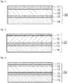
- the thermal transfer image-receiving sheet 10 includes, as illustrated in Figs. 1 and 2 , a receiving layer 11, a front substrate 12, a porous layer 13, and a rear substrate 14.
- the thermal transfer image-receiving sheet 10 further includes a metal-containing layer 15 interposed between the receiving layer 11 and the front substrate 12 or between the front substrate 12 and the porous layer 13.
- the thermal transfer image-receiving sheet 10 includes, as illustrated in Fig. 3 , a primer layer 16 interposed between the receiving layer 11 and the front substrate 12.
- the thermal transfer image-receiving sheet 10 includes an adhesive layer 17 interposed between any two layers, such as between the metal-containing layer 15 and the porous layer 13 or between the porous layer 13 and the rear substrate 14, as illustrated in Fig. 4 .
- the thermal transfer image-receiving sheet 10 includes, as illustrated in Fig. 5 , a rear surface layer 18 disposed below the rear substrate 14.
- the thermal transfer image-receiving sheet according to the present disclosure includes an intermediate layer (not illustrated in the drawing) that is a layer adjacent to the porous layer 13.
- the thermal transfer image-receiving sheet according to the present disclosure includes a porous layer, a front substrate, and a receiving layer (not illustrated in the drawing) disposed below the rear substrate. This allows images to be formed on both surfaces of the thermal transfer image-receiving sheet.
- the thermal conductivity of the thermal transfer image-receiving sheet according to the present disclosure is 0.38 W/m.K or less. This enhances the density of an image that is to be formed on the receiving layer and the transferability of the protective layer to the receiving layer.
- the thermal conductivity of the thermal transfer image-receiving sheet is preferably 0.30 W/m ⁇ K or more and 0.38 W/m ⁇ K or less and is further preferably 0.33 W/m.K or more and 0.37 W/m.K or less.
- thermal conductivity is measured on the receiving layer-side of the thermal transfer image-receiving sheet using a thermal conductivity meter (QTM-500 produced by Kyoto Electronics Manufacturing Co., Ltd.) in accordance with the transient hot wire method described in JIS R 2616 (published in 2001).
- QTM-500 produced by Kyoto Electronics Manufacturing Co., Ltd.
- the Martens hardness of the thermal transfer image-receiving sheet according to the present disclosure is 10.0 N/mm 2 or less. This enhances the density of an image that is to be formed on the receiving layer and the transferability of the protective layer to the receiving layer.
- the Martens hardness of the thermal transfer image-receiving sheet is preferably 10.0 N/mm 2 or less and is further preferably 8.0 N/mm 2 or less.
- the above Martens hardness is particularly preferably 5.0 N/mm 2 or less in order to effectively reduce the likelihood of the thermal transfer image-receiving sheet curling when the thermal transfer image-receiving sheet is left to stand or when an image is formed on the thermal transfer image-receiving sheet and the thermal transfer image-receiving sheet is then left to stand (hereinafter, this phenomenon may be referred to simply as "curling inhibiting property").
- Martens hardness is measured on the receiving layer-side of the thermal transfer image-receiving sheet using a hardness meter (FISCHERSCOPE H100VS produced by Fitech) in accordance with ISO 14577:2002.
- FISCHERSCOPE H100VS produced by Fitech
- the 45-degree specular gloss of the thermal transfer image-receiving sheet according to the present disclosure is 800 or more. This enables the production of a printed material having high glossiness.
- the 45-degree specular gloss of the thermal transfer image-receiving sheet is more preferably 1000 or more.
- the 45-degree specular gloss of the thermal transfer image-receiving sheet is determined by measuring the 45-degree specular gloss of the receiving layer using a gloss meter (VG 7000 produced by Nippon Denshoku Industries Co., Ltd.) in accordance with the method for measuring 45-degree specular gloss described in JIS Z 8741 (published in 1997).
- VG 7000 produced by Nippon Denshoku Industries Co., Ltd.
- the receiving layer is a layer that receives a sublimation dye and maintains the resulting image.
- the receiving layer contains at least one resin material.
- the resin material is transparent. Examples thereof include an olefin resin, a vinyl resin, a (meth)acrylic resin, a cellulose resin, a polyester, an amide resin, a polycarbonate, a styrene resin, a urethane resin, and an ionomer resin.
- the content of the resin material in the receiving layer is preferably 80% by mass or more and 98% by mass or less and is further preferably 90% by mass or more and 98% by mass or less.
- the receiving layer contains at least one release agent. This enhances releasability from a thermal transfer sheet.
- release agent examples include a solid wax, a surfactant, a silicone oil, and a silicone resin.
- solid wax examples include a polyethylene wax, an amide wax, and a Teflon (registered trademark) powder.
- surfactant examples include a fluorinated surfactant and a phosphoric acid ester surfactant.
- the silicone oil is preferably a modified silicone oil.
- modified silicone oil include amino-modified silicone, epoxy-modified silicone, aralkyl-modified silicone, epoxy aralkyl-modified silicone, alcohol-modified silicone, vinyl-modified silicone, and urethane-modified silicone.
- epoxy-modified silicone, aralkyl-modified silicone, and epoxy aralkyl-modified silicone are particularly preferable.
- the content of the release agent in the receiving layer is preferably 0.5% by mass or more and 20% by mass or less and is further preferably 0.5% by mass or more and 10% by mass or less. This enables releasability from a thermal transfer sheet to be enhanced while maintaining the transparency of the receiving layer.
- the receiving layer may contain additives.
- the additives include a plasticizer, a filler, an ultraviolet stabilizer, an anti-coloring agent, a surfactant, a fluorescent whitener, a delustering agent, a deodorizer, a fire retardant, an weatherproofing agent, an antistatic agent, a yarn friction-reducing agent, a slipping agent, an antioxidant, an ion exchanger, a dispersant, an ultraviolet absorber, and coloring materials, such as a pigment and a dye.
- the thickness of the receiving layer is preferably 0.5 ⁇ m or more and 20 ⁇ m or less and is further preferably 1.0 ⁇ m or more and 10 ⁇ m or less. This further enhances the density of an image that is to be formed on the receiving layer and the property of reducing the likelihood of the thermal transfer image-receiving sheet curling in a concave manner.
- the receiving layer can be formed by dispersing or dissolving the above materials in water or an appropriate solvent, applying the resulting coating liquid onto the front substrate or the like, and drying the resulting coating film.
- various coating methods known in the related art such as roll coating, reverse roll coating, gravure coating, reverse gravure coating, bar coating, and rod coating, may be used.
- a film made of a resin material can be used as a front substrate.
- the resin material include polyesters, such as polyethylene terephthalate (PET), polybutylene terephthalate (PBT), polyethylene naphthalate (PEN), 1,4-polycyclohexylenedimethylene terephthalate, and a terephthalic acid-cyclohexanedimethanol-ethylene glycol copolymer; polyamides, such as Nylon 6 and Nylon 6,6; polyolefins, such as polyethylene (PE), polypropylene (PP), and polymethylpentene; vinyl resins, such as polyvinyl chloride, polyvinyl alcohol (PVA), polyvinyl acetate, a vinyl chloride-vinyl acetate copolymer, polyvinyl butyral, and polyvinylpyrrolidone (PVP); (meth)acrylic resins, such as
- polyesters are preferable, PET and PEN are further preferable, and PET is particularly preferable in terms of mechanical strength and glossiness.
- the front substrate may be required to have high transparency and high glossiness in consideration of the specular glossiness of a printed material.
- polyesters are preferable and PET and PEN are further preferable.
- a colored substrate or a substrate including a coloring layer may be also used as a front substrate.
- a substrate including inorganic or organic particles may be also used as a front substrate.
- the transparency of the front substrate is not limited.
- an opaque white film formed of a mixture of the resin material with a white pigment and a filler and a film having voids formed therein may be also used.
- (meth)acryl used herein includes both “acryl” and “methacryl”.
- (meth)acrylate used herein includes both “acrylate” and “methacrylate”.
- a laminate including two or more films described above that are stacked on top of one another may be used as a substrate.
- the laminate can be formed using dry lamination, wet lamination, extrusion, or the like.
- the thickness of the front substrate is preferably 5 ⁇ m or more and 150 ⁇ m or less, is more preferably 7 ⁇ m or more and 75 ⁇ m or less, is further preferably 10 ⁇ m or more and 50 ⁇ m or less, and is particularly preferably 10 ⁇ m or more and 23 ⁇ m or less. This further enhances curling inhibiting property.
- the resin film may be either a stretched or unstretched film. In terms of strength, a uniaxially or biaxially stretched film is preferable.
- the thermal transfer image-receiving sheet according to the present disclosure includes at least one porous layer. This enhances the density of an image that is to be formed on the receiving and the transferability of the protective layer onto the receiving layer.
- the porous layer is constituted by a porous film having fine voids formed therein.
- the resin material constituting the porous film examples include polyolefins, such as PE and PP; vinyl resins, such as polyvinyl acetate, a vinyl chloride-vinyl acetate copolymer, and an ethylene-vinyl acetate copolymer; polyesters, such as PET and PBT; styrene resins; and polyamides.
- PP and PET are particularly preferable in terms of the flatness and smoothness, thermal insulation properties, and cushioning properties of the film.
- the porous film may contain the above additives.
- the porous film can be produced by a common method known in the related art.
- the porous film can be produced by, for example, kneading the above resin material with organic or inorganic particles immiscible with the resin material and forming the resulting mixture into a film.
- the porous film can be produced by, for example, mixing a first resin material with a second resin material having a higher melting temperature than the first resin material and forming the resulting mixture into a film.
- the porous film is not limited to a porous film produced by any of the above-described methods; commercially available porous films may be also used.
- the thickness of the porous film is preferably 10 ⁇ m or more and 100 ⁇ m or less, is further preferably 15 ⁇ m or more and 50 ⁇ m or less, and is particularly preferably 16 ⁇ m or more and 30 ⁇ m or less. This further enhances the density of an image that is to be formed on the receiving layer and the transferability of the protective layer onto the receiving layer. Furthermore, curling inhibiting property can be enhanced.
- the porous layer is a hollow particle-containing layer that contains hollow particles and a binder material.
- the hollow particles may be organic hollow particles made of a resin material or the like or inorganic hollow particles made of glass or the like. Organic hollow particles are preferably used in order to enhance dispersibility.
- Examples of the resin material constituting the organic hollow particles include a styrene resin, a (meth)acrylic resin, a phenolic resin, a fluororesin, a polyamide, an imide resin, and a polycarbonate.
- the hollow particles may be either foamed particles or non-foamed particles.
- the hollow particles can be prepared by, for example, adding a blowing agent, such as a butane gas, into resin particles or the like and heating the resin particles to induce foaming.
- a blowing agent such as a butane gas
- the hollow particles can be also prepared by using emulsion polymerization.
- hollow particles may be used.
- binder material contained in the hollow particle-containing layer examples include a polyurethane, a polyester, a cellulose resin, a vinyl resin, a (meth)acrylic resin, a polyolefin, a styrene resin, gelatin and derivatives thereof, a styrene acrylic acid ester, polyvinyl alcohol, polyethylene oxide, polyvinylpyrrolidone, pullulan, dextran, dextrin, polyacrylic acid and salts thereof, agar, ⁇ -carrageenan, ⁇ -carrageenan, ⁇ -carrageenan, casein, xanthan gum, locust bean gum, alginic acid, and gum arabic.
- a styrene acrylic acid ester is preferably used in order to impart the functions of an adhesive layer to the porous layer.
- the content of the binder material in the hollow particle-containing layer is preferably 20% by mass or more and 75% by mass or less and is further preferably 50% by mass or more and 70% by mass or less. This further enhances the density of an image that is to be formed on the receiving layer and the transferability of the protective layer onto the receiving layer.
- the hollow particle-containing layer may contain the above additives.
- the thickness of the hollow particle-containing layer is preferably 10 ⁇ m or more and 100 ⁇ m or less, is further preferably 15 ⁇ m or more and 50 ⁇ m or less, and is particularly preferably 16 ⁇ m or more and 30 ⁇ m or less. This further enhances the density of an image that is to be formed on the receiving layer and the transferability of the protective layer onto the receiving layer. Furthermore, curling inhibiting property can be enhanced.
- the hollow particle-containing layer can be formed by dispersing or dissolving the above materials in water or an appropriate solvent, applying the resulting coating liquid onto an appropriate layer by any of the above-described coating methods, and drying the resulting coating film.
- a paper substrate or the above-described resin film can be used as a rear substrate.
- the paper substrate include condenser paper, glassine paper, sulfuric acid paper, synthetic paper, woodfree paper, art paper, coated paper, uncoated paper, cast coated paper, wall paper, cellulose fiber paper, synthetic resin-containing paper, lining paper, and impregnated paper (synthetic resin-impregnated paper, emulsion-impregnated paper, or synthetic rubber latex-impregnated paper).
- An opaque white film formed using a white pigment and a filler and a film having voids formed therein may be also used as a resin film.
- coated paper and uncoated paper are preferable in terms of transportability inside a printer and mechanical strength.
- a laminate including the above paper substrate and the above resin film stacked on top of each other may be also used.
- the thickness of the rear substrate is preferably 50 ⁇ m or more and 300 ⁇ m or less in consideration of mechanical strength.
- the thickness of the rear substrate is further preferably 90 ⁇ m or more and 165 ⁇ m or less in consideration of curling inhibiting property.
- the resin film may be either a stretched or unstretched film. In terms of strength, a uniaxially or biaxially stretched film is preferable.
- the metal-containing layer is a vapor-deposited film.
- the type of the vapor-deposited film is not limited; the vapor-deposited film can be formed using a metal, such as aluminum, zinc, silicon, magnesium, calcium, potassium, tin, sodium, titanium, lead, or zirconium, or an oxide of the metal.
- the thickness of the vapor-deposited film is, for example, 1 nm or more and 150 nm or less.
- the vapor-deposited film can be formed on the surface of the front substrate or the like by a common method known in the related art.
- the known method include physical vapor deposition (PVD), such as vacuum vapor deposition, sputtering, or ion plating; and chemical vapor deposition (CVD), such as plasma-enhanced chemical vapor deposition, thermal chemical vapor deposition, or photochemical vapor deposition.
- PVD physical vapor deposition
- CVD chemical vapor deposition
- the metal-containing layer contains at least one metal pigment and at least one resin material.
- the metal pigment examples include particles of aluminum, nickel, chromium, brass, tin, brass, bronze, zinc, silver, platinum, gold, and oxides of the above metals; and glass particles on which a metal has been deposited by vapor deposition.
- the content of the metal pigment in the metal-containing layer is preferably 20% by mass or more and 80% by mass or less and is further preferably 30% by mass or more and 75% by mass or less. This further enhances glossiness.
- the resin material examples include a polyester, a polyamide, a polyolefin, a vinyl resin, a (meth)acrylic resin, a cellulose resin, a styrene resin, a polycarbonate, and an ionomer resin.
- the metal-containing layer may contain the above additives.
- the thickness of the metal-containing layer is preferably 0.5 ⁇ m or more and 5 ⁇ m or less and is further preferably 1 ⁇ m or more and 3 ⁇ m or less. This further enhances the specular glossiness of the printed material produced.
- the metal-containing layer can be formed by dispersing or dissolving the above materials in water or an appropriate solvent, applying the resulting coating liquid onto the front substrate or the like by any of the above-described coating methods, and drying the resulting coating film.
- the metal-containing layer is constituted by a metal foil.
- the metal foil can be appropriately selected from metal foils made of gold, silver, copper, aluminum, zinc, or the like.
- the thickness of the metal foil is preferably 5 ⁇ m or more and 50 ⁇ m or less and is further preferably 10 ⁇ m or more and 30 ⁇ m or less. This further enhances the specular glossiness of the printed material produced.
- the metal foil may be either a metal foil prepared by a common method known in the related art or a commercially available metal foil.
- the metal foil can be stacked on one of the surfaces of the front substrate or the like with, for example, the adhesive layer, which is described below, being interposed therebetween.
- the thermal transfer image-receiving sheet according to the present disclosure includes a primer layer interposed between the front substrate and the receiving layer or between the metal-containing layer and the receiving layer. This increases the adhesion between the two layers.
- the primer layer includes a resin material.
- the resin material is not limited and may be any transparent resin material that enables the intended 45-degree specular gloss to be achieved. Examples thereof include a polyester, a polyurethane, a polycarbonate, a (meth)acrylic resin, a styrene resin, a vinyl resin, and a cellulose resin.
- the primer layer may contain the above additives.
- the thickness of the primer layer is, for example, 0.1 ⁇ m or more and 3.0 ⁇ m or less .
- the hollow particle-containing layer can be formed by dispersing or dissolving the above materials in water or an appropriate solvent, applying the resulting coating liquid onto the front substrate, the metal-containing layer, or the like by any of the above-described coating methods, and drying the resulting coating film.
- the thermal transfer image-receiving sheet according to the present disclosure includes an adhesive layer interposed between any two layers. This increases the adhesion between the two layers.
- the adhesive layer contains a resin material.
- resin material examples thereof include vinyl resins, such as polyvinyl acetate, PVB, an ethylene-vinyl acetate copolymer, and a vinyl chloride-vinyl acetate copolymer; polyolefins, such as PE and PP; polyesters, such as PET and PBT; a polyamide; an imide resin; (meth)acrylic resins, such as a polyacrylate, a polymethacrylate, and a polymethyl methacrylate; cellulose resins, such as cellulose diastase; polyol resins; and polyurethanes.
- vinyl resins such as polyvinyl acetate, PVB, an ethylene-vinyl acetate copolymer, and a vinyl chloride-vinyl acetate copolymer
- polyolefins such as PE and PP
- polyesters such as PET and PBT
- a polyamide such as PET and PBT
- an imide resin
- the adhesive layer preferably contains an isocyanate compound.
- the adhesive layer may contain the above additives.
- the thickness of the adhesive layer is, for example, 0.5 ⁇ m or more and 10 ⁇ m or less.
- the adhesive layer can be formed by dispersing or dissolving the above materials in water or an appropriate solvent, applying the resulting coating liquid onto an appropriate layer by any of the above-described coating methods, and drying the resulting coating film.
- the adhesive layer can be formed by melt-extruding a resin composition containing the above materials.
- the thermal transfer image-receiving sheet according to the present disclosure includes a rear surface layer disposed below the rear substrate. This enhances the transportability of the thermal transfer image-receiving sheet in a printer. Furthermore, curling inhibiting property can be further enhanced.
- the rear surface layer contains at least one resin material.
- resin material examples thereof include a polyolefin, a vinyl resin, a (meth)acrylic resin, a cellulose resin, a polyester, a polyamide, a polycarbonate, a styrene resin, and a polyurethane.
- a polyolefin is preferable and a polyethylene is further preferable in terms of curling inhibiting property.
- Low-density polyethylene LDPE, density: 0.910 g/cm 3 or more and less than 0.930 g/cm 3
- high-density polyethylene HDPE, density: 0.942 g/cm 3 or more
- the ratio between the contents of HDPE and LDPE is preferably, by mass, 1/9 or more and 9/1 or less and is further preferably, by mass, 3/7 or more and 9/1 or less. This further enhances curling inhibiting property and further improves transportability in a printer.
- the rear surface layer contains a filler.
- the filler include an organic filler made of a resin material, such as a (meth)acrylic resin, a polyamide, or a polyolefin; and an inorganic filler made of an inorganic material, such as silicon dioxide particles, calcium carbonate particles, or titanium oxide particles.
- an organic-inorganic hybrid filler may be also used.
- the rear surface layer may contain the above additives.
- the thickness of the rear surface layer is preferably 1 ⁇ m or more and 50 ⁇ m or less, is more preferably 5 ⁇ m or more and 35 ⁇ m or less, and is further preferably 8 ⁇ m or more and 28 ⁇ m or less. This further enhances curling inhibiting property and further improves transportability in a printer.
- the rear surface layer can be formed by dispersing or dissolving the above materials in water or an appropriate solvent, applying the resulting coating liquid onto the rear substrate or the like by any of the above-described coating methods, and drying the resulting coating film.
- the rear surface layer can be also formed by melt-extruding the above materials onto the rear substrate or the like (melt-extruded layer). This method makes it easy to adjust the thickness of the rear surface layer and further enhances curling inhibiting property.
- the thermal transfer image-receiving sheet according to the present disclosure includes an intermediate layer that is a layer adjacent to the porous layer. Since the degree of flatness and smoothness of the surface of the porous layer (in particular, the hollow particle-containing layer) may be low, the adhesion of the porous layer to the front substrate, the metal-containing layer, the rear substrate, or the like may be reduced. Arranging an intermediate layer adjacent to the porous layer enhances the flatness and smoothness of the surface of the porous layer and thereby increases the adhesion of the porous layer to the front substrate, the metal-containing layer, the rear substrate, or the like.
- the intermediate layer may be disposed either above or below the porous layer.
- the intermediate layer may be disposed both above and below the porous layer.
- the intermediate layer contains a resin material.
- a resin material examples thereof include a polyester, a polyurethane, a polycarbonate, a (meth)acrylic resin, a styrene resin, a vinyl resin, and a cellulose resin.
- the intermediate layer may contain the above additives.
- the thickness of the intermediate layer is, for example, 0.1 ⁇ m or more and 3.0 ⁇ m or less.
- the intermediate layer can be formed by dispersing or dissolving the above materials in water or an appropriate solvent, applying the resulting coating liquid onto the porous layer by any of the above-described coating methods, and drying the resulting coating film.
- a printed material 20 according to the present disclosure is a printed material fabricated using the above-described thermal transfer image-receiving sheet.
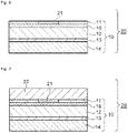
- the printed material 20 includes, as illustrated in Fig. 6 , a receiving layer 11, a metal-containing layer 15, a front substrate 12, a porous layer 13, and a rear substrate 14.
- An image 21 is formed on or in the receiving layer 11.
- Fig. 6 illustrates a case where the metal-containing layer 15 is interposed between the receiving layer 11 and the front substrate 12, the layer arrangement is not limited to this; alternatively, the metal-containing layer 15 may be interposed between the front substrate 12 and the porous layer 13.
- the printed material 20 includes, as illustrated in Fig. 7 , a protective layer 22 disposed on the receiving layer 11, on or in which an image is formed.
- the protective layer may be disposed on only a part of the receiving layer.
- the printed material includes an image formed on the receiving layer.
- the types of the image is not limited and may be a character, a texture, a symbol, or a combination thereof.
- the method for forming an image on the receiving layer is not limited.
- the image can be formed on the receiving layer by using a common sublimation thermal transfer recording-type or thermofusible transfer recording-type thermal transfer sheet known in the related art.
- a protective layer is disposed on the receiving layer. This enhances the abrasion resistance, preservation stability, etc. of the image formed on the receiving layer.
- the protective layer contains at least one resin material.
- the resin material is not limited and may be any transparent resin material. Examples thereof include a (meth)acrylic resin, a styrene resin, a vinyl resin, a polyolefin, a polyester, a polyamide, an imide resin, a cellulose resin, a thermosetting resin, and an active light-curable resin.
- active light-cured resin refers to an active light-curable resin cured by being irradiated with active light.
- active light refers to radiation that chemically acts on an active light-curable resin and facilitates polymerization and specifically to visible light, ultraviolet light, X-ray, an electron beam, ⁇ -ray, ⁇ -ray, and ⁇ -ray.
- the content of the resin material in the protective layer is not limited but is preferably 50% by mass or more and 95% by mass or less in consideration of the abrasion resistance and preservation stability of the image.
- the protective layer may contain the above additives.
- the thickness of the protective layer is preferably 3 ⁇ m or more and 10 ⁇ m or less and is further preferably 5 ⁇ m or more and 10 ⁇ m or less. This further enhances the abrasion resistance, preservation stability, etc. of the image.
- PET film A having a thickness of 25 ⁇ m (Metalight K-Y-27-CR produced by Toyobo Co., Ltd.), which included an aluminum film having a thickness of 45 nm which was vapor-deposited on one of the surfaces, was provided as a front substrate.
- An adhesive layer-forming coating liquid having the following formulation was applied onto the surface of the front substrate on which the vapor-deposited film was present.
- the resulting coating film was dried to form an adhesive layer having a thickness of 2.4 ⁇ m.
- a porous PP film A SP-U produced by Mitsui Chemicals Tohcello Inc., thickness: 36 ⁇ m, which served as a porous layer, was stacked on the front substrate with the adhesive layer being interposed therebetween.
- An adhesive layer-forming coating liquid having the above formulation was applied onto a surface of the porous PP film A which was opposite to the surface on which the front substrate was stacked.
- the resulting coating film was dried to form an adhesive layer having a thickness of 2.4 ⁇ m.
- a coated paper sheet A (Utrillo (registered trademark) 157 produced by Nippon Paper Industries Co., Ltd., thickness: 130 ⁇ m), which served as a rear substrate, was stacked on the porous layer with the adhesive layer being interposed therebetween.
- a primer layer-forming coating liquid having the following formulation was applied onto a surface of the front substrate on which the vapor-deposited film was absent.
- the resulting coating film was dried to form a primer layer having a thickness of 2.5 ⁇ m.
- a receiving layer-forming coating liquid having the following formulation was applied onto the primer layer.
- the resulting coating film was dried to form a receiving layer having a thickness of 4 ⁇ m.
- a thermal transfer image-receiving sheet according to the present disclosure was obtained.
- a thermal transfer image-receiving sheet was fabricated as in Example 1, except that the porous PP film A was changed to a porous PET film A (FK003 produced by Toyobo Co., Ltd., thickness: 38 ⁇ m).
- a coated paper sheet A was provided as a rear substrate.
- a porous layer-forming coating liquid having the following formulation was applied onto the coated paper sheet A.
- the resulting coating film was dried to form a porous layer having a thickness of 30 ⁇ m.
- An intermediate layer-forming coating liquid having the following formulation was applied onto the porous layer.
- the resulting coating film was dried to form an intermediate layer having a thickness of 2 ⁇ m.
- a laminate including a rear substrate, a porous layer, and an intermediate layer was obtained.
- a PET film A was provided as a front substrate.
- An adhesive layer coating liquid having the above formulation was applied onto a surface of the front substrate on which a vapor-deposited film was present.
- the resulting coating film was dried to form an adhesive layer having a thickness of 2.4 ⁇ m.
- the front substrate was stacked on the surface of the intermediate layer side of the laminate fabricated in the above-described manner, with the adhesive layer being interposed therebetween.
- the resin composition A was melt-extruded onto the other surface of the rear substrate to form a rear surface layer having a thickness of 24 ⁇ m.
- a primer layer-forming coating liquid having the above formulation was applied onto a surface of the front substrate on which the porous layer was not formed.
- the resulting coating film was dried to form a primer layer having a thickness of 2.5 ⁇ m.
- a receiving layer-forming coating liquid having the above formulation was applied onto the primer layer.
- the resulting coating film was dried to form a receiving layer having a thickness of 4 ⁇ m.
- a thermal transfer image-receiving sheet according to the present disclosure was obtained.
- a PET film A was provided as a front substrate.
- An adhesive layer-forming coating liquid having the above formulation was applied onto a surface of the front substrate on which the vapor-deposited film was absent.
- the resulting coating film was dried to form an adhesive layer having a thickness of 2.4 ⁇ m.
- a porous PP film A used as a porous layer was stacked on the front substrate with the adhesive layer being interposed therebetween.
- An adhesive layer-forming coating liquid having the above formulation was applied onto a surface of the porous PP film A which was opposite to the surface on which the front substrate was stacked.
- the resulting coating film was dried to form an adhesive layer having a thickness of 2.4 ⁇ m.
- a coated paper sheet A used as a rear substrate was stacked on the porous layer with the adhesive layer being interposed therebetween.
- the resin composition A was melt-extruded onto a surface of the rear substrate which was opposite to the surface on which the porous PP film A was stacked, in order to form a rear surface layer having a thickness of 24 ⁇ m.
- a primer layer-forming coating liquid having the above formulation was applied onto a surface of the front substrate on which a vapor-deposited film was present.
- the resulting coating film was dried to form a primer layer having a thickness of 2.5 ⁇ m.
- a receiving layer-forming coating liquid having the above formulation was applied onto the primer layer.
- the resulting coating film was dried to form a receiving layer having a thickness of 4 ⁇ m.
- a thermal transfer image-receiving sheet according to the present disclosure was obtained.
- a thermal transfer image-receiving sheet was obtained as in Example 1, except that the thickness of the rear surface layer was changed to 16 ⁇ m.
- a thermal transfer image-receiving sheet was obtained as in Example 1, except that the porous PP film A was changed to a porous PP film B (SP-U produced by Mitsui Chemicals Tohcello Inc., thickness: 23 ⁇ m) and the thickness of the rear surface layer was changed to 16 ⁇ m.
- the porous PP film A was changed to a porous PP film B (SP-U produced by Mitsui Chemicals Tohcello Inc., thickness: 23 ⁇ m) and the thickness of the rear surface layer was changed to 16 ⁇ m.
- a thermal transfer image-receiving sheet was obtained as in Example 1, except that the front substrate was changed to a PET film B (BR-PET1012 produced by Toray Industries, Inc., thickness: 12 ⁇ m) including an aluminum film having a thickness of 45 nm which was vapor-deposited on one of the surfaces, the rear substrate was changed to an uncoated paper sheet A (Noncoat K-156 produced by Kitakami HiTec Paper Corporation, thickness: 156 ⁇ m), and the thickness of the rear surface layer was changed to 16 ⁇ m.
- a PET film B BR-PET1012 produced by Toray Industries, Inc., thickness: 12 ⁇ m
- an aluminum film having a thickness of 45 nm which was vapor-deposited on one of the surfaces the rear substrate was changed to an uncoated paper sheet A (Noncoat K-156 produced by Kitakami HiTec Paper Corporation, thickness: 156 ⁇ m), and the thickness of the rear surface layer was changed to 16 ⁇ m.
- a thermal transfer image-receiving sheet was obtained as in Example 1, except that the front substrate was changed to a PET film B.
- a thermal transfer image-receiving sheet was obtained as in Example 1, except that the front substrate was changed to a PET film B and the rear substrate was changed to an uncoated paper sheet A.
- a thermal transfer image-receiving sheet was obtained as in Example 1, except that the front substrate was changed to a PET film B, the porous PP film A was changed to a porous PP film B, and the rear substrate was changed to an uncoated paper sheet A.
- a thermal transfer image-receiving sheet was obtained as in Example 1, except that the front substrate was changed to a PET film B, the porous PP film A was changed to a porous PP film B, the rear substrate was changed to an uncoated paper sheet A, and the thickness of the rear surface layer was changed to 16 ⁇ m.
- a PET film B was provided as a front substrate.
- a porous PP film B was provided as a porous layer.
- the resin composition A was melt-extruded into a gap between the surface of the front substrate on which a vapor-deposited film was present and the porous PP film B to form an adhesive layer having a thickness of 14 ⁇ m and allow the two layers to be stacked on top of each other.
- An adhesive layer-forming coating liquid having the above formulation was applied onto a surface of the porous PP film B on which the adhesive layer was not formed.
- the resulting coating film was dried to form an adhesive layer having a thickness of 2.4 ⁇ m.
- An uncoated paper sheet A, which served as a rear substrate, was stacked on the porous layer with the adhesive layer being interposed therebetween.
- the resin composition A was melt-extruded onto a surface of the rear substrate which was opposite to the surface on which the porous PP film B was stacked, in order to form a rear surface layer having a thickness of 16 ⁇ m.
- a primer layer-forming coating liquid having the above formulation was applied onto the other surface of the front substrate.
- the resulting coating film was dried to form a primer layer having a thickness of 2.5 ⁇ m.
- a receiving layer-forming coating liquid having the above formulation was applied onto the primer layer.
- the resulting coating film was dried to form a receiving layer having a thickness of 4 ⁇ m.
- a thermal transfer image-receiving sheet according to the present disclosure was obtained.
- a PET film A was provided as a front substrate.
- An adhesive layer coating liquid having the above formulation was applied onto a surface of the front substrate on which a vapor-deposited film was present.
- the resulting coating film was dried to form an adhesive layer having a thickness of 2.4 ⁇ m.
- a coated paper sheet A, which served as a rear substrate, was stacked on the front substrate with the adhesive layer being interposed therebetween.
- the resin composition A was melt-extruded onto a surface of the rear substrate which was opposite to the surface on which the PET film A was stacked, in order to form a rear surface layer having a thickness of 30 ⁇ m.
- a primer layer-forming coating liquid having the above formulation was applied onto the other surface of the front substrate.
- the resulting coating film was dried to form a primer layer having a thickness of 2.5 ⁇ m.
- a receiving layer-forming coating liquid having the above formulation was applied onto the primer layer.
- the resulting coating film was dried to form a receiving layer having a thickness of 4 ⁇ m.
- a thermal transfer image-receiving sheet was obtained.
- a thermal transfer image-receiving sheet was fabricated as in Example 1, except that the porous PP film A was changed to a porous PP film C (thickness: 10 ⁇ m).
- a porous PP film A was provided as a porous layer.
- An adhesive layer-forming coating liquid having the above formulation was applied onto one of the surfaces of the porous PP film A.
- the resulting coating film was dried to form an adhesive layer having a thickness of 2.4 ⁇ m.
- a coated paper sheet A, which served as a rear substrate, was stacked on the porous layer with the adhesive layer being interposed therebetween.
- the resin composition A containing HDPE and LDPE was melt-extruded onto a surface of the rear substrate which was opposite to the surface on which the porous PP film A was stacked, in order to form a rear surface layer having a thickness of 30 ⁇ m.
- a primer layer-forming coating liquid having the above formulation was applied onto the other surface of the porous PP film.
- the resulting coating film was dried to form a primer layer having a thickness of 2.5 ⁇ m.
- a receiving layer-forming coating liquid having the above formulation was applied onto the primer layer.
- the resulting coating film was dried to form a receiving layer having a thickness of 4 ⁇ m.
- a thermal transfer image-receiving sheet was obtained.
- thermal conductivity of each of the thermal transfer image-receiving sheets obtained in Examples and Comparative examples was measured with a thermal conductivity meter (QTM-500 produced by Kyoto Electronics Manufacturing Co., Ltd.) in accordance with the transient hot wire method described in JIS R 2616 (published in 2001). Table 1 lists the measurement results.
- thermal conductivity was measured on the receiving layer-side of the thermal transfer image-receiving sheet in a room temperature environment.
- Martens hardness was measured on the receiving layer-side of the thermal transfer image-receiving sheet in a room temperature environment.
- the 45-degree specular gloss of each of the thermal transfer image-receiving sheets obtained in Examples and Comparative examples was measured with a gloss meter (VG 7000 produced by Nippon Denshoku Industries Co., Ltd.) in accordance with the method for measuring 45-degree specular gloss described in JIS Z 8741 (published in 1997). In the measurement, the 45-degree specular gloss on the receiving layer was measured. Table 1 lists the measurement results.
- thermo transfer image-receiving sheets obtained in Examples and Comparative examples above A specific one of the thermal transfer image-receiving sheets obtained in Examples and Comparative examples above, a sublimation thermal transfer printer (DS620 produced by Dai Nippon Printing Co., Ltd.), and a genuine ribbon for the above printer, which included a dye layer containing a sublimation dye and a protective layer, were provided.
- DS620 produced by Dai Nippon Printing Co., Ltd.
- a white solid image was printed in a 20°C/30%RH environment in order to obtain a printed material that included the protective layer transferred on the receiving layer. Note that the printer was set to a gloss mode. The color shades of the white solid image was 255/255.
- the resulting printed material was visually inspected and evaluated in accordance with the following evaluation standard. Table 1 lists the evaluation results.
- thermo transfer image-receiving sheets obtained in Examples and Comparative examples above, the above sublimation thermal transfer printer, and the genuine ribbon for the above printer were provided.
- a black solid image was printed in a 20°C/30%RH environment in order to obtain a printed material. Note that the printer was set to a gloss mode. The color shades of the black solid image was 0/255.
- the density of the image of the resulting printed material was measured with an optical densitometer ("i1Pro2" produced by X-Rite, Inc.) and evaluated in accordance with the following evaluation standard. Table 1 lists the evaluation results.
- a gray solid image was formed on the receiving layer included in a specific one of the thermal transfer image-receiving sheets obtained in Examples and Comparative examples above with the above sublimation thermal transfer printer and the genuine ribbon for the above printer.
- a printed material having a length of 152.4 mm and a width of 203.2 mm was obtained.
- the printer was set to a gloss mode.
- the color shades of the gray solid image was 128/255.
- the above printed material was left to stand in an environment of 35°C and a relative humidity of 15% for 100 hours.
- the printed material that had been left to stand was placed on a flat stage, and the heights of the four corners from the stage were measured. Specifically, in the case where the printed material was curled such that the receiving layer-side surface was concave, the printed material was placed on the flat stage with the receiving layer-side surface facing upward. In the case where the printed material was curled such that the receiving layer-side surface was convex, the printed material was placed on the flat stage with the receiving layer-side surface facing downward. The heights of the four corners from the stage were averaged to determine the average amount of curling, which was evaluated in accordance with the following evaluation standard. Table 1 lists the evaluation results.
- the average amount of curling was determined as in "Evaluation of Curling Inhibiting Property - 1", except that the printed material was left to stand in an environment of 20°C and a relative humidity of 60% for 1 week.
- the average amount of curling was evaluated in accordance with the following evaluation standard. Table 1 lists the evaluation results.
- thermo transfer image-receiving sheets obtained in Examples and Comparative examples above was cut into a size having a length of 152.4 mm and a width of 5.5 mm to form a specimen.
- This specimen was left to stand in an environment of 35°C and a relative humidity of 15% for 100 hours.
- the specimen that had been left to stand was placed on a flat stage, and the heights of the four corners from the stage were measured. Specifically, in the case where the specimen was curled such that the receiving layer-side surface was concave, the specimen was placed on the flat stage with the receiving layer-side surface facing upward. In the case where the specimen was curled such that the receiving layer-side surface was convex, the specimen was placed on the flat stage with the receiving layer-side surface facing downward. The heights of both ends from the stage were averaged to determine the average amount of curling, which was evaluated in accordance with the following evaluation standard. Table 1 lists the evaluation results.
- thermal transfer image-receiving sheet and a printed material according to an embodiment of the present disclosure are described below. Note that the thermal transfer sheet and the printed material according to the present disclosure are not limited to the embodiment.
- the thermal transfer image-receiving sheet according to the present disclosure includes a receiving layer, a front substrate, a porous layer, and a rear substrate in this order.
- the thermal transfer image-receiving sheet further includes a metal-containing layer interposed between the receiving layer and the front substrate or between the front substrate and the porous layer.
- the thermal conductivity of the thermal transfer image-receiving sheet which is measured on the receiving layer-side of the thermal transfer image-receiving sheet is 0.38 W/m ⁇ K or less.
- the Martens hardness of the thermal transfer image-receiving sheet which is measured on the receiving layer-side is 10.0 N/mm 2 or less.
- the 45-degree specular gloss of the thermal transfer image-receiving sheet which is measured on the receiving layer-side is 800 or more.
- the porous layer is a polyethylene terephthalate film or a polypropylene film.
- the porous layer has a thickness of 10 ⁇ m or more and 50 ⁇ m or less.
- the metal-containing layer is a vapor-deposited film formed on the surface of the front substrate.
- the Martens hardness of the thermal transfer image-receiving sheet which is measured on the receiving layer-side is 5.0 N/mm 2 or less.
- the printed material according to the present disclosure is a printed material produced using the above-described thermal transfer image-receiving sheet.
- the printed material includes a protective layer disposed on the receiving layer.
Landscapes
- Physics & Mathematics (AREA)
- Optics & Photonics (AREA)
- Chemical & Material Sciences (AREA)
- Inorganic Chemistry (AREA)
- Thermal Transfer Or Thermal Recording In General (AREA)
- Saccharide Compounds (AREA)
- Non-Silver Salt Photosensitive Materials And Non-Silver Salt Photography (AREA)
- Radiation-Therapy Devices (AREA)
Abstract
Description
- The present disclosure relates to a thermal transfer image-receiving sheet and a printed material.
- Various types of printing methods have been known in the related art. Among those, a sublimation thermal transfer printing method enables color shades to be readily adjusted at will, therefore has excellent reproducibility of intermediate colors and shades, and enables the formation of high-quality images comparable to silver halide prints.
- A sublimation thermal transfer printing method is a method for producing a printed material, the method including superimposing a thermal transfer sheet including a dye layer and a thermal transfer image-receiving sheet including a receiving layer on each other and heating the thermal transfer sheet with a thermal head included in a printer in order to cause a sublimation dye included in the dye layer to transfer to the receiving layer included in the thermal transfer image-receiving sheet and form an image.
- There has been an approach to transferring a protective layer from the thermal transfer sheet onto the receiving layer included in the printed material produced by the above-described method in order to enhance the durability and the like of the printed material.
- Printed materials produced by a sublimation thermal transfer printing method are required to have a great variety of graphical design functions. For example, the printed materials are required to have high specular glossiness.
- A thermal transfer image-receiving sheet that includes a receiving layer, a front substrate, a metal-containing layer, a rear substrate, and a rear surface layer has been used in order to manufacture printed materials having high specular glossiness.
- There has been a demand for a further increase in the image density of a printed material produced using the thermal transfer image-receiving sheet that includes a metal-containing layer. In addition, when a protective layer is transferred onto a receiving layer, a part of the protective layer may fail to be transferred. Thus, there has been room for improvement in terms of protective layer transferability.
- An object of the present disclosure is to provide a thermal transfer image-receiving sheet that improves the density of an image that is to be formed on the receiving layer, that has high protective layer transferability, and that enables the production of a printed material having high specular glossiness and a printed material produced using the thermal transfer image-receiving sheet.
- The thermal transfer image-receiving sheet according to the present disclosure includes a receiving layer, a front substrate, a porous layer, and a rear substrate in this order,
- the thermal transfer image-receiving sheet further including a metal-containing layer interposed between the receiving layer and the front substrate or between the front substrate and the porous layer,
- wherein a thermal conductivity of the thermal transfer image-receiving sheet, the thermal conductivity being measured on a receiving layer-side of the thermal transfer image-receiving sheet, is 0.38 W/m.K or less,
- wherein a Martens hardness of the thermal transfer image-receiving sheet, the Martens hardness being measured on the receiving layer-side, is 10.0 N/mm2 or less, and
- wherein a 45-degree specular gloss of the thermal transfer image-receiving sheet, the 45-degree specular gloss being measured on the receiving layer-side, is 800 or more.
- The printed material according to the present disclosure is a printed material produced using the above-described thermal transfer image-receiving sheet,
- wherein an image is formed on the receiving layer, and
- wherein the printed material includes a protective layer disposed on the receiving layer.
- According to the present disclosure, a thermal transfer image-receiving sheet that improves the density of an image that is to be formed on the receiving layer, that has high protective layer transferability, and that enables the production of a printed material having high specular glossiness can be provided.
- According to the present disclosure, a printed material produced using the thermal transfer image-receiving sheet can be also provided. Brief Description of Drawings
-
- [
Fig. 1] Fig. 1 is a schematic cross-sectional view of an embodiment of a thermal transfer image-receiving sheet according to the present disclosure. - [
Fig. 2] Fig. 2 is a schematic cross-sectional view of an embodiment of a thermal transfer image-receiving sheet according to the present disclosure. - [
Fig. 3] Fig. 3 is a schematic cross-sectional view of an embodiment of a thermal transfer image-receiving sheet according to the present disclosure. - [
Fig. 4] Fig. 4 is a schematic cross-sectional view of an embodiment of a thermal transfer image-receiving sheet according to the present disclosure. - [
Fig. 5] Fig. 5 is a schematic cross-sectional view of an embodiment of a thermal transfer image-receiving sheet according to the present disclosure. - [
Fig. 6] Fig. 6 is a schematic cross-sectional view of an embodiment of a printed material according to the present disclosure. - [
Fig. 7] Fig. 7 is a schematic cross-sectional view of an embodiment of a printed material according to the present disclosure. Description of Embodiments - The thermal transfer image-
receiving sheet 10 according to the present disclosure includes, as illustrated inFigs. 1 and 2 , a receivinglayer 11, afront substrate 12, aporous layer 13, and arear substrate 14. The thermal transfer image-receiving sheet 10 further includes a metal-containinglayer 15 interposed between thereceiving layer 11 and thefront substrate 12 or between thefront substrate 12 and theporous layer 13. - In one embodiment, the thermal transfer image-
receiving sheet 10 according to the present disclosure includes, as illustrated inFig. 3 , aprimer layer 16 interposed between thereceiving layer 11 and thefront substrate 12. - In one embodiment, the thermal transfer image-
receiving sheet 10 according to the present disclosure includes anadhesive layer 17 interposed between any two layers, such as between the metal-containinglayer 15 and theporous layer 13 or between theporous layer 13 and therear substrate 14, as illustrated inFig. 4 . - In one embodiment, the thermal transfer image-
receiving sheet 10 according to the present disclosure includes, as illustrated inFig. 5 , arear surface layer 18 disposed below therear substrate 14. - In one embodiment, the thermal transfer image-receiving sheet according to the present disclosure includes an intermediate layer (not illustrated in the drawing) that is a layer adjacent to the
porous layer 13. - In one embodiment, the thermal transfer image-receiving sheet according to the present disclosure includes a porous layer, a front substrate, and a receiving layer (not illustrated in the drawing) disposed below the rear substrate. This allows images to be formed on both surfaces of the thermal transfer image-receiving sheet.
- The thermal conductivity of the thermal transfer image-receiving sheet according to the present disclosure is 0.38 W/m.K or less. This enhances the density of an image that is to be formed on the receiving layer and the transferability of the protective layer to the receiving layer.
- In consideration of image density and protective layer transferability, the thermal conductivity of the thermal transfer image-receiving sheet is preferably 0.30 W/m·K or more and 0.38 W/m·K or less and is further preferably 0.33 W/m.K or more and 0.37 W/m.K or less.
- In the present disclosure, thermal conductivity is measured on the receiving layer-side of the thermal transfer image-receiving sheet using a thermal conductivity meter (QTM-500 produced by Kyoto Electronics Manufacturing Co., Ltd.) in accordance with the transient hot wire method described in JIS R 2616 (published in 2001).
- The Martens hardness of the thermal transfer image-receiving sheet according to the present disclosure is 10.0 N/mm2 or less. This enhances the density of an image that is to be formed on the receiving layer and the transferability of the protective layer to the receiving layer.
- In consideration of image density and protective layer transferability, the Martens hardness of the thermal transfer image-receiving sheet is preferably 10.0 N/mm2 or less and is further preferably 8.0 N/mm2 or less. The above Martens hardness is particularly preferably 5.0 N/mm2 or less in order to effectively reduce the likelihood of the thermal transfer image-receiving sheet curling when the thermal transfer image-receiving sheet is left to stand or when an image is formed on the thermal transfer image-receiving sheet and the thermal transfer image-receiving sheet is then left to stand (hereinafter, this phenomenon may be referred to simply as "curling inhibiting property").
- In the present disclosure, Martens hardness is measured on the receiving layer-side of the thermal transfer image-receiving sheet using a hardness meter (FISCHERSCOPE H100VS produced by Fitech) in accordance with ISO 14577:2002.
- The 45-degree specular gloss of the thermal transfer image-receiving sheet according to the present disclosure is 800 or more. This enables the production of a printed material having high glossiness.
- The 45-degree specular gloss of the thermal transfer image-receiving sheet is more preferably 1000 or more.
- In the present disclosure, the 45-degree specular gloss of the thermal transfer image-receiving sheet is determined by measuring the 45-degree specular gloss of the receiving layer using a gloss meter (VG 7000 produced by Nippon Denshoku Industries Co., Ltd.) in accordance with the method for measuring 45-degree specular gloss described in JIS Z 8741 (published in 1997).
- Details of each of the layers included in the thermal transfer image-receiving sheet according to the present disclosure are described below.
- The receiving layer is a layer that receives a sublimation dye and maintains the resulting image.
- The receiving layer contains at least one resin material. The resin material is transparent. Examples thereof include an olefin resin, a vinyl resin, a (meth)acrylic resin, a cellulose resin, a polyester, an amide resin, a polycarbonate, a styrene resin, a urethane resin, and an ionomer resin.
- The content of the resin material in the receiving layer is preferably 80% by mass or more and 98% by mass or less and is further preferably 90% by mass or more and 98% by mass or less.
- In one embodiment, the receiving layer contains at least one release agent. This enhances releasability from a thermal transfer sheet.
- Examples of the release agent include a solid wax, a surfactant, a silicone oil, and a silicone resin.
- Examples of the solid wax include a polyethylene wax, an amide wax, and a Teflon (registered trademark) powder.
- Examples of the surfactant include a fluorinated surfactant and a phosphoric acid ester surfactant.
- The silicone oil is preferably a modified silicone oil. Examples of the modified silicone oil include amino-modified silicone, epoxy-modified silicone, aralkyl-modified silicone, epoxy aralkyl-modified silicone, alcohol-modified silicone, vinyl-modified silicone, and urethane-modified silicone. Among these, epoxy-modified silicone, aralkyl-modified silicone, and epoxy aralkyl-modified silicone are particularly preferable.
- The content of the release agent in the receiving layer is preferably 0.5% by mass or more and 20% by mass or less and is further preferably 0.5% by mass or more and 10% by mass or less. This enables releasability from a thermal transfer sheet to be enhanced while maintaining the transparency of the receiving layer.
- The receiving layer may contain additives. Examples of the additives include a plasticizer, a filler, an ultraviolet stabilizer, an anti-coloring agent, a surfactant, a fluorescent whitener, a delustering agent, a deodorizer, a fire retardant, an weatherproofing agent, an antistatic agent, a yarn friction-reducing agent, a slipping agent, an antioxidant, an ion exchanger, a dispersant, an ultraviolet absorber, and coloring materials, such as a pigment and a dye.
- The thickness of the receiving layer is preferably 0.5 µm or more and 20 µm or less and is further preferably 1.0 µm or more and 10 µm or less. This further enhances the density of an image that is to be formed on the receiving layer and the property of reducing the likelihood of the thermal transfer image-receiving sheet curling in a concave manner.
- The receiving layer can be formed by dispersing or dissolving the above materials in water or an appropriate solvent, applying the resulting coating liquid onto the front substrate or the like, and drying the resulting coating film. For coating, various coating methods known in the related art, such as roll coating, reverse roll coating, gravure coating, reverse gravure coating, bar coating, and rod coating, may be used.
- A film made of a resin material (hereinafter, such a film is referred to simply as "resin film") can be used as a front substrate. Examples of the resin material include polyesters, such as polyethylene terephthalate (PET), polybutylene terephthalate (PBT), polyethylene naphthalate (PEN), 1,4-polycyclohexylenedimethylene terephthalate, and a terephthalic acid-cyclohexanedimethanol-ethylene glycol copolymer; polyamides, such as Nylon 6 and Nylon 6,6; polyolefins, such as polyethylene (PE), polypropylene (PP), and polymethylpentene; vinyl resins, such as polyvinyl chloride, polyvinyl alcohol (PVA), polyvinyl acetate, a vinyl chloride-vinyl acetate copolymer, polyvinyl butyral, and polyvinylpyrrolidone (PVP); (meth)acrylic resins, such as a polyacrylate and a polymethacrylate; imide resins, such as a polyimide and a polyether imide; cellulose resins, such as cellophane, cellulose acetate, nitrocellulose, cellulose acetate propionate (CAP), and cellulose acetate butyrate (CAB); styrene resins, such as polystyrene (PS); polycarbonates; and ionomer resins.
- Among the above resin materials, polyesters are preferable, PET and PEN are further preferable, and PET is particularly preferable in terms of mechanical strength and glossiness.
- In the case where the metal-containing layer is interposed between the front substrate and the porous layer, that is, in the case where the metal-containing layer is disposed below the front substrate, the front substrate may be required to have high transparency and high glossiness in consideration of the specular glossiness of a printed material. In terms of transparency and glossiness, among the above resin materials, polyesters are preferable and PET and PEN are further preferable. A colored substrate or a substrate including a coloring layer may be also used as a front substrate. A substrate including inorganic or organic particles may be also used as a front substrate.
- In the case where the front substrate is interposed between the metal-containing layer and the porous layer, that is, the metal-containing layer is disposed above the front substrate, the transparency of the front substrate is not limited. For example, an opaque white film formed of a mixture of the resin material with a white pigment and a filler and a film having voids formed therein may be also used.
- The term "(meth)acryl" used herein includes both "acryl" and "methacryl". The term "(meth)acrylate" used herein includes both "acrylate" and "methacrylate".
- A laminate including two or more films described above that are stacked on top of one another may be used as a substrate. The laminate can be formed using dry lamination, wet lamination, extrusion, or the like.
- The thickness of the front substrate is preferably 5 µm or more and 150 µm or less, is more preferably 7 µm or more and 75 µm or less, is further preferably 10 µm or more and 50 µm or less, and is particularly preferably 10 µm or more and 23 µm or less. This further enhances curling inhibiting property.
- In the case where the front substrate is a resin film, the resin film may be either a stretched or unstretched film. In terms of strength, a uniaxially or biaxially stretched film is preferable.
- The thermal transfer image-receiving sheet according to the present disclosure includes at least one porous layer. This enhances the density of an image that is to be formed on the receiving and the transferability of the protective layer onto the receiving layer.
- In one embodiment, the porous layer is constituted by a porous film having fine voids formed therein.
- Examples of the resin material constituting the porous film include polyolefins, such as PE and PP; vinyl resins, such as polyvinyl acetate, a vinyl chloride-vinyl acetate copolymer, and an ethylene-vinyl acetate copolymer; polyesters, such as PET and PBT; styrene resins; and polyamides.
- Among these, PP and PET are particularly preferable in terms of the flatness and smoothness, thermal insulation properties, and cushioning properties of the film.
- The porous film may contain the above additives.
- The porous film can be produced by a common method known in the related art. The porous film can be produced by, for example, kneading the above resin material with organic or inorganic particles immiscible with the resin material and forming the resulting mixture into a film.
- In one embodiment, the porous film can be produced by, for example, mixing a first resin material with a second resin material having a higher melting temperature than the first resin material and forming the resulting mixture into a film.
- The porous film is not limited to a porous film produced by any of the above-described methods; commercially available porous films may be also used.
- The thickness of the porous film is preferably 10 µm or more and 100 µm or less, is further preferably 15 µm or more and 50 µm or less, and is particularly preferably 16 µm or more and 30 µm or less. This further enhances the density of an image that is to be formed on the receiving layer and the transferability of the protective layer onto the receiving layer. Furthermore, curling inhibiting property can be enhanced.
- In one embodiment, the porous layer is a hollow particle-containing layer that contains hollow particles and a binder material.
- The hollow particles may be organic hollow particles made of a resin material or the like or inorganic hollow particles made of glass or the like. Organic hollow particles are preferably used in order to enhance dispersibility.
- Examples of the resin material constituting the organic hollow particles include a styrene resin, a (meth)acrylic resin, a phenolic resin, a fluororesin, a polyamide, an imide resin, and a polycarbonate.
- The hollow particles may be either foamed particles or non-foamed particles.
- In one embodiment, the hollow particles can be prepared by, for example, adding a blowing agent, such as a butane gas, into resin particles or the like and heating the resin particles to induce foaming. In one embodiment, the hollow particles can be also prepared by using emulsion polymerization.
- Alternatively, commercially available hollow particles may be used.
- Examples of the binder material contained in the hollow particle-containing layer include a polyurethane, a polyester, a cellulose resin, a vinyl resin, a (meth)acrylic resin, a polyolefin, a styrene resin, gelatin and derivatives thereof, a styrene acrylic acid ester, polyvinyl alcohol, polyethylene oxide, polyvinylpyrrolidone, pullulan, dextran, dextrin, polyacrylic acid and salts thereof, agar, κ-carrageenan, λ-carrageenan, ι-carrageenan, casein, xanthan gum, locust bean gum, alginic acid, and gum arabic. Among these, a styrene acrylic acid ester is preferably used in order to impart the functions of an adhesive layer to the porous layer.
- The content of the binder material in the hollow particle-containing layer is preferably 20% by mass or more and 75% by mass or less and is further preferably 50% by mass or more and 70% by mass or less. This further enhances the density of an image that is to be formed on the receiving layer and the transferability of the protective layer onto the receiving layer.
- The hollow particle-containing layer may contain the above additives.
- The thickness of the hollow particle-containing layer is preferably 10 µm or more and 100 µm or less, is further preferably 15 µm or more and 50 µm or less, and is particularly preferably 16 µm or more and 30 µm or less. This further enhances the density of an image that is to be formed on the receiving layer and the transferability of the protective layer onto the receiving layer. Furthermore, curling inhibiting property can be enhanced.
- The hollow particle-containing layer can be formed by dispersing or dissolving the above materials in water or an appropriate solvent, applying the resulting coating liquid onto an appropriate layer by any of the above-described coating methods, and drying the resulting coating film.
- A paper substrate or the above-described resin film can be used as a rear substrate. Examples of the paper substrate include condenser paper, glassine paper, sulfuric acid paper, synthetic paper, woodfree paper, art paper, coated paper, uncoated paper, cast coated paper, wall paper, cellulose fiber paper, synthetic resin-containing paper, lining paper, and impregnated paper (synthetic resin-impregnated paper, emulsion-impregnated paper, or synthetic rubber latex-impregnated paper).
- An opaque white film formed using a white pigment and a filler and a film having voids formed therein may be also used as a resin film.
- Among these, coated paper and uncoated paper are preferable in terms of transportability inside a printer and mechanical strength.
- A laminate including the above paper substrate and the above resin film stacked on top of each other may be also used.
- The thickness of the rear substrate is preferably 50 µm or more and 300 µm or less in consideration of mechanical strength. The thickness of the rear substrate is further preferably 90 µm or more and 165 µm or less in consideration of curling inhibiting property.
- In the case where the rear substrate is a resin film, the resin film may be either a stretched or unstretched film. In terms of strength, a uniaxially or biaxially stretched film is preferable.
- In a first aspect, the metal-containing layer is a vapor-deposited film. The type of the vapor-deposited film is not limited; the vapor-deposited film can be formed using a metal, such as aluminum, zinc, silicon, magnesium, calcium, potassium, tin, sodium, titanium, lead, or zirconium, or an oxide of the metal.
- The thickness of the vapor-deposited film is, for example, 1 nm or more and 150 nm or less.
- The vapor-deposited film can be formed on the surface of the front substrate or the like by a common method known in the related art. Examples of the known method include physical vapor deposition (PVD), such as vacuum vapor deposition, sputtering, or ion plating; and chemical vapor deposition (CVD), such as plasma-enhanced chemical vapor deposition, thermal chemical vapor deposition, or photochemical vapor deposition.
- In a second aspect, the metal-containing layer contains at least one metal pigment and at least one resin material.
- Examples of the metal pigment include particles of aluminum, nickel, chromium, brass, tin, brass, bronze, zinc, silver, platinum, gold, and oxides of the above metals; and glass particles on which a metal has been deposited by vapor deposition.
- The content of the metal pigment in the metal-containing layer is preferably 20% by mass or more and 80% by mass or less and is further preferably 30% by mass or more and 75% by mass or less. This further enhances glossiness.
- Examples of the resin material include a polyester, a polyamide, a polyolefin, a vinyl resin, a (meth)acrylic resin, a cellulose resin, a styrene resin, a polycarbonate, and an ionomer resin.
- The metal-containing layer may contain the above additives.
- In the second aspect, the thickness of the metal-containing layer is preferably 0.5 µm or more and 5 µm or less and is further preferably 1 µm or more and 3 µm or less. This further enhances the specular glossiness of the printed material produced.
- In the second aspect, the metal-containing layer can be formed by dispersing or dissolving the above materials in water or an appropriate solvent, applying the resulting coating liquid onto the front substrate or the like by any of the above-described coating methods, and drying the resulting coating film.
- In a third aspect, the metal-containing layer is constituted by a metal foil. The metal foil can be appropriately selected from metal foils made of gold, silver, copper, aluminum, zinc, or the like.
- The thickness of the metal foil is preferably 5 µm or more and 50 µm or less and is further preferably 10 µm or more and 30 µm or less. This further enhances the specular glossiness of the printed material produced.
- The metal foil may be either a metal foil prepared by a common method known in the related art or a commercially available metal foil. The metal foil can be stacked on one of the surfaces of the front substrate or the like with, for example, the adhesive layer, which is described below, being interposed therebetween.
- In one embodiment, the thermal transfer image-receiving sheet according to the present disclosure includes a primer layer interposed between the front substrate and the receiving layer or between the metal-containing layer and the receiving layer. This increases the adhesion between the two layers.
- The primer layer includes a resin material. The resin material is not limited and may be any transparent resin material that enables the intended 45-degree specular gloss to be achieved. Examples thereof include a polyester, a polyurethane, a polycarbonate, a (meth)acrylic resin, a styrene resin, a vinyl resin, and a cellulose resin.
- The primer layer may contain the above additives.
- The thickness of the primer layer is, for example, 0.1 µm or more and 3.0 µm or less.
- The hollow particle-containing layer can be formed by dispersing or dissolving the above materials in water or an appropriate solvent, applying the resulting coating liquid onto the front substrate, the metal-containing layer, or the like by any of the above-described coating methods, and drying the resulting coating film.
- The thermal transfer image-receiving sheet according to the present disclosure includes an adhesive layer interposed between any two layers. This increases the adhesion between the two layers.
- The adhesive layer contains a resin material. Examples thereof include vinyl resins, such as polyvinyl acetate, PVB, an ethylene-vinyl acetate copolymer, and a vinyl chloride-vinyl acetate copolymer; polyolefins, such as PE and PP; polyesters, such as PET and PBT; a polyamide; an imide resin; (meth)acrylic resins, such as a polyacrylate, a polymethacrylate, and a polymethyl methacrylate; cellulose resins, such as cellulose diastase; polyol resins; and polyurethanes.
- In the case where the adhesive layer contains a polyol resin, the adhesive layer preferably contains an isocyanate compound.
- The adhesive layer may contain the above additives.
- The thickness of the adhesive layer is, for example, 0.5 µm or more and 10 µm or less.
- The adhesive layer can be formed by dispersing or dissolving the above materials in water or an appropriate solvent, applying the resulting coating liquid onto an appropriate layer by any of the above-described coating methods, and drying the resulting coating film.
- In one embodiment, the adhesive layer can be formed by melt-extruding a resin composition containing the above materials.
- In one embodiment, the thermal transfer image-receiving sheet according to the present disclosure includes a rear surface layer disposed below the rear substrate. This enhances the transportability of the thermal transfer image-receiving sheet in a printer. Furthermore, curling inhibiting property can be further enhanced.
- The rear surface layer contains at least one resin material. Examples thereof include a polyolefin, a vinyl resin, a (meth)acrylic resin, a cellulose resin, a polyester, a polyamide, a polycarbonate, a styrene resin, and a polyurethane.
- Among these, a polyolefin is preferable and a polyethylene is further preferable in terms of curling inhibiting property. Low-density polyethylene (LDPE, density: 0.910 g/cm3 or more and less than 0.930 g/cm3) and high-density polyethylene (HDPE, density: 0.942 g/cm3 or more) are particularly preferable.
- The ratio between the contents of HDPE and LDPE (HDPE content/LDPE content) is preferably, by mass, 1/9 or more and 9/1 or less and is further preferably, by mass, 3/7 or more and 9/1 or less. This further enhances curling inhibiting property and further improves transportability in a printer.
- In one embodiment, the rear surface layer contains a filler. Examples of the filler include an organic filler made of a resin material, such as a (meth)acrylic resin, a polyamide, or a polyolefin; and an inorganic filler made of an inorganic material, such as silicon dioxide particles, calcium carbonate particles, or titanium oxide particles. Alternatively, an organic-inorganic hybrid filler may be also used.
- The rear surface layer may contain the above additives.
- The thickness of the rear surface layer is preferably 1 µm or more and 50 µm or less, is more preferably 5 µm or more and 35 µm or less, and is further preferably 8 µm or more and 28 µm or less. This further enhances curling inhibiting property and further improves transportability in a printer.
- The rear surface layer can be formed by dispersing or dissolving the above materials in water or an appropriate solvent, applying the resulting coating liquid onto the rear substrate or the like by any of the above-described coating methods, and drying the resulting coating film.
- Alternatively, the rear surface layer can be also formed by melt-extruding the above materials onto the rear substrate or the like (melt-extruded layer). This method makes it easy to adjust the thickness of the rear surface layer and further enhances curling inhibiting property.
- In one embodiment, the thermal transfer image-receiving sheet according to the present disclosure includes an intermediate layer that is a layer adjacent to the porous layer. Since the degree of flatness and smoothness of the surface of the porous layer (in particular, the hollow particle-containing layer) may be low, the adhesion of the porous layer to the front substrate, the metal-containing layer, the rear substrate, or the like may be reduced. Arranging an intermediate layer adjacent to the porous layer enhances the flatness and smoothness of the surface of the porous layer and thereby increases the adhesion of the porous layer to the front substrate, the metal-containing layer, the rear substrate, or the like.
- The intermediate layer may be disposed either above or below the porous layer. The intermediate layer may be disposed both above and below the porous layer.
- The intermediate layer contains a resin material. Examples thereof include a polyester, a polyurethane, a polycarbonate, a (meth)acrylic resin, a styrene resin, a vinyl resin, and a cellulose resin.
- The intermediate layer may contain the above additives.
- The thickness of the intermediate layer is, for example, 0.1 µm or more and 3.0 µm or less.
- The intermediate layer can be formed by dispersing or dissolving the above materials in water or an appropriate solvent, applying the resulting coating liquid onto the porous layer by any of the above-described coating methods, and drying the resulting coating film.
- A printed
material 20 according to the present disclosure is a printed material fabricated using the above-described thermal transfer image-receiving sheet. The printedmaterial 20 includes, as illustrated inFig. 6 , a receivinglayer 11, a metal-containinglayer 15, afront substrate 12, aporous layer 13, and arear substrate 14. Animage 21 is formed on or in the receivinglayer 11. AlthoughFig. 6 illustrates a case where the metal-containinglayer 15 is interposed between the receivinglayer 11 and thefront substrate 12, the layer arrangement is not limited to this; alternatively, the metal-containinglayer 15 may be interposed between thefront substrate 12 and theporous layer 13. - In one embodiment, the printed
material 20 according to the present disclosure includes, as illustrated inFig. 7 , aprotective layer 22 disposed on the receivinglayer 11, on or in which an image is formed. The protective layer may be disposed on only a part of the receiving layer. - Details of each of the layers included in the printed material according to the present disclosure are described below. The layers having the same structures as in the thermal transfer image-receiving sheet are not described hereinafter.
- The printed material includes an image formed on the receiving layer. The types of the image is not limited and may be a character, a texture, a symbol, or a combination thereof. The method for forming an image on the receiving layer is not limited. The image can be formed on the receiving layer by using a common sublimation thermal transfer recording-type or thermofusible transfer recording-type thermal transfer sheet known in the related art.
- A protective layer is disposed on the receiving layer. This enhances the abrasion resistance, preservation stability, etc. of the image formed on the receiving layer.
- The protective layer contains at least one resin material. The resin material is not limited and may be any transparent resin material. Examples thereof include a (meth)acrylic resin, a styrene resin, a vinyl resin, a polyolefin, a polyester, a polyamide, an imide resin, a cellulose resin, a thermosetting resin, and an active light-curable resin.
- The term "active light-cured resin" used herein refers to an active light-curable resin cured by being irradiated with active light.
- The term "active light" used herein refers to radiation that chemically acts on an active light-curable resin and facilitates polymerization and specifically to visible light, ultraviolet light, X-ray, an electron beam, α-ray, β-ray, and γ-ray.
- The content of the resin material in the protective layer is not limited but is preferably 50% by mass or more and 95% by mass or less in consideration of the abrasion resistance and preservation stability of the image.
- The protective layer may contain the above additives.
- The thickness of the protective layer is preferably 3 µm or more and 10 µm or less and is further preferably 5 µm or more and 10 µm or less. This further enhances the abrasion resistance, preservation stability, etc. of the image.
- The present disclosure is described further in detail with reference to Examples below. Note that the present disclosure is not limited by Examples below.
- A PET film A having a thickness of 25 µm (Metalight K-Y-27-CR produced by Toyobo Co., Ltd.), which included an aluminum film having a thickness of 45 nm which was vapor-deposited on one of the surfaces, was provided as a front substrate.
- An adhesive layer-forming coating liquid having the following formulation was applied onto the surface of the front substrate on which the vapor-deposited film was present. The resulting coating film was dried to form an adhesive layer having a thickness of 2.4 µm. A porous PP film A (SP-U produced by Mitsui Chemicals Tohcello Inc., thickness: 36 µm), which served as a porous layer, was stacked on the front substrate with the adhesive layer being interposed therebetween.
-
• Polyol resin: 30 parts by mass - (TAKELAC (registered trademark) A-969V produced by Mitsui Chemicals, Inc.)
• Isocyanate compound: 10 parts by mass - (TAKENATE (registered trademark) A-5 produced by Mitsui Chemicals, Inc.)
• Ethyl acetate: 60 parts by mass - An adhesive layer-forming coating liquid having the above formulation was applied onto a surface of the porous PP film A which was opposite to the surface on which the front substrate was stacked. The resulting coating film was dried to form an adhesive layer having a thickness of 2.4 µm. A coated paper sheet A (Utrillo (registered trademark) 157 produced by Nippon Paper Industries Co., Ltd., thickness: 130 µm), which served as a rear substrate, was stacked on the porous layer with the adhesive layer being interposed therebetween.
- A resin composition A containing HDPE and LDPE (HDPE:LDPE = 8:2) was melt-extruded onto a surface of the rear substrate which was opposite to the surface on which the porous PP film A was stacked, in order to form a rear surface layer having a thickness of 24 µm.
- A primer layer-forming coating liquid having the following formulation was applied onto a surface of the front substrate on which the vapor-deposited film was absent. The resulting coating film was dried to form a primer layer having a thickness of 2.5 µm.
-
• Urethane resin: 30 parts by mass - (NIPPOLLAN (registered trademark) produced by Tosoh Corporation)
• Methyl ethyl ketone (MEK): 15 parts by mass - A receiving layer-forming coating liquid having the following formulation was applied onto the primer layer. The resulting coating film was dried to form a receiving layer having a thickness of 4 µm. Hereby, a thermal transfer image-receiving sheet according to the present disclosure was obtained.
-
• Vinyl chloride-vinyl acetate copolymer: 60 parts by mass - (SOLBIN (registered trademark) C produced by Nissin Chemical Industry Co., Ltd.)
• Epoxy-modified silicone resin: 1.2 parts by mass - (X-22-3000T produced by Shin-Etsu Chemical Co., Ltd.)
• Methylstyl-modified silicone resin: 0.6 parts by mass - (X-24-510 produced by Shin-Etsu Chemical Co., Ltd.)
• MEK: 2.5 parts by mass • Toluene: 2.5 parts by mass - A thermal transfer image-receiving sheet was fabricated as in Example 1, except that the porous PP film A was changed to a porous PET film A (FK003 produced by Toyobo Co., Ltd., thickness: 38 µm).
- A coated paper sheet A was provided as a rear substrate. A porous layer-forming coating liquid having the following formulation was applied onto the coated paper sheet A. The resulting coating film was dried to form a porous layer having a thickness of 30 µm.
-
• Hollow particles: 70 parts by mass - (HP-91 produced by Rohm and Haas Company, average particle size: 1 µm)
- Styrene acrylic acid ester: 30 parts by mass
- (SX1707A produced by Zeon Corporation)
• Water: 10 parts by mass - An intermediate layer-forming coating liquid having the following formulation was applied onto the porous layer. The resulting coating film was dried to form an intermediate layer having a thickness of 2 µm. Hereby, a laminate including a rear substrate, a porous layer, and an intermediate layer was obtained.
-
• (Meth)acrylic resin: 100 parts by mass - (B-4100 produced by Mitsui Chemicals, Inc., solid content: 37%)
• Polyvinylpyrrolidone: 77 parts by mass - (VIVI PRINT540 produced by ISP Japan, solid content: 12%)
• Water: 30 parts by mass • Isopropyl alcohol (IPA): 24 parts by mass - Subsequently, a PET film A was provided as a front substrate. An adhesive layer coating liquid having the above formulation was applied onto a surface of the front substrate on which a vapor-deposited film was present. The resulting coating film was dried to form an adhesive layer having a thickness of 2.4 µm. Then, the front substrate was stacked on the surface of the intermediate layer side of the laminate fabricated in the above-described manner, with the adhesive layer being interposed therebetween.
- The resin composition A was melt-extruded onto the other surface of the rear substrate to form a rear surface layer having a thickness of 24 µm.
- A primer layer-forming coating liquid having the above formulation was applied onto a surface of the front substrate on which the porous layer was not formed. The resulting coating film was dried to form a primer layer having a thickness of 2.5 µm.
- A receiving layer-forming coating liquid having the above formulation was applied onto the primer layer. The resulting coating film was dried to form a receiving layer having a thickness of 4 µm. Hereby, a thermal transfer image-receiving sheet according to the present disclosure was obtained.
- A PET film A was provided as a front substrate.
- An adhesive layer-forming coating liquid having the above formulation was applied onto a surface of the front substrate on which the vapor-deposited film was absent. The resulting coating film was dried to form an adhesive layer having a thickness of 2.4 µm. A porous PP film A used as a porous layer was stacked on the front substrate with the adhesive layer being interposed therebetween.
- An adhesive layer-forming coating liquid having the above formulation was applied onto a surface of the porous PP film A which was opposite to the surface on which the front substrate was stacked. The resulting coating film was dried to form an adhesive layer having a thickness of 2.4 µm. A coated paper sheet A used as a rear substrate was stacked on the porous layer with the adhesive layer being interposed therebetween.
- The resin composition A was melt-extruded onto a surface of the rear substrate which was opposite to the surface on which the porous PP film A was stacked, in order to form a rear surface layer having a thickness of 24 µm.
- A primer layer-forming coating liquid having the above formulation was applied onto a surface of the front substrate on which a vapor-deposited film was present. The resulting coating film was dried to form a primer layer having a thickness of 2.5 µm.
- A receiving layer-forming coating liquid having the above formulation was applied onto the primer layer. The resulting coating film was dried to form a receiving layer having a thickness of 4 µm. Hereby, a thermal transfer image-receiving sheet according to the present disclosure was obtained.
- A thermal transfer image-receiving sheet was obtained as in Example 1, except that the thickness of the rear surface layer was changed to 16 µm.
- A thermal transfer image-receiving sheet was obtained as in Example 1, except that the porous PP film A was changed to a porous PP film B (SP-U produced by Mitsui Chemicals Tohcello Inc., thickness: 23 µm) and the thickness of the rear surface layer was changed to 16 µm.
- A thermal transfer image-receiving sheet was obtained as in Example 1, except that the front substrate was changed to a PET film B (BR-PET1012 produced by Toray Industries, Inc., thickness: 12 µm) including an aluminum film having a thickness of 45 nm which was vapor-deposited on one of the surfaces, the rear substrate was changed to an uncoated paper sheet A (Noncoat K-156 produced by Kitakami HiTec Paper Corporation, thickness: 156 µm), and the thickness of the rear surface layer was changed to 16 µm.
- A thermal transfer image-receiving sheet was obtained as in Example 1, except that the front substrate was changed to a PET film B.
- A thermal transfer image-receiving sheet was obtained as in Example 1, except that the front substrate was changed to a PET film B and the rear substrate was changed to an uncoated paper sheet A.
- A thermal transfer image-receiving sheet was obtained as in Example 1, except that the front substrate was changed to a PET film B, the porous PP film A was changed to a porous PP film B, and the rear substrate was changed to an uncoated paper sheet A.
- A thermal transfer image-receiving sheet was obtained as in Example 1, except that the front substrate was changed to a PET film B, the porous PP film A was changed to a porous PP film B, the rear substrate was changed to an uncoated paper sheet A, and the thickness of the rear surface layer was changed to 16 µm.
- A PET film B was provided as a front substrate. A porous PP film B was provided as a porous layer.
- The resin composition A was melt-extruded into a gap between the surface of the front substrate on which a vapor-deposited film was present and the porous PP film B to form an adhesive layer having a thickness of 14 µm and allow the two layers to be stacked on top of each other.
- An adhesive layer-forming coating liquid having the above formulation was applied onto a surface of the porous PP film B on which the adhesive layer was not formed. The resulting coating film was dried to form an adhesive layer having a thickness of 2.4 µm. An uncoated paper sheet A, which served as a rear substrate, was stacked on the porous layer with the adhesive layer being interposed therebetween.
- The resin composition A was melt-extruded onto a surface of the rear substrate which was opposite to the surface on which the porous PP film B was stacked, in order to form a rear surface layer having a thickness of 16 µm.
- A primer layer-forming coating liquid having the above formulation was applied onto the other surface of the front substrate. The resulting coating film was dried to form a primer layer having a thickness of 2.5 µm.
- A receiving layer-forming coating liquid having the above formulation was applied onto the primer layer. The resulting coating film was dried to form a receiving layer having a thickness of 4 µm. Hereby, a thermal transfer image-receiving sheet according to the present disclosure was obtained.
- A PET film A was provided as a front substrate.
- An adhesive layer coating liquid having the above formulation was applied onto a surface of the front substrate on which a vapor-deposited film was present. The resulting coating film was dried to form an adhesive layer having a thickness of 2.4 µm. A coated paper sheet A, which served as a rear substrate, was stacked on the front substrate with the adhesive layer being interposed therebetween.
- The resin composition A was melt-extruded onto a surface of the rear substrate which was opposite to the surface on which the PET film A was stacked, in order to form a rear surface layer having a thickness of 30 µm.
- A primer layer-forming coating liquid having the above formulation was applied onto the other surface of the front substrate. The resulting coating film was dried to form a primer layer having a thickness of 2.5 µm.
- A receiving layer-forming coating liquid having the above formulation was applied onto the primer layer. The resulting coating film was dried to form a receiving layer having a thickness of 4 µm. Hereby, a thermal transfer image-receiving sheet was obtained.
- A thermal transfer image-receiving sheet was fabricated as in Example 1, except that the porous PP film A was changed to a porous PP film C (thickness: 10 µm).
- A porous PP film A was provided as a porous layer.
- An adhesive layer-forming coating liquid having the above formulation was applied onto one of the surfaces of the porous PP film A. The resulting coating film was dried to form an adhesive layer having a thickness of 2.4 µm. A coated paper sheet A, which served as a rear substrate, was stacked on the porous layer with the adhesive layer being interposed therebetween.
- The resin composition A containing HDPE and LDPE was melt-extruded onto a surface of the rear substrate which was opposite to the surface on which the porous PP film A was stacked, in order to form a rear surface layer having a thickness of 30 µm.
- A primer layer-forming coating liquid having the above formulation was applied onto the other surface of the porous PP film. The resulting coating film was dried to form a primer layer having a thickness of 2.5 µm.
- A receiving layer-forming coating liquid having the above formulation was applied onto the primer layer. The resulting coating film was dried to form a receiving layer having a thickness of 4 µm. Hereby, a thermal transfer image-receiving sheet was obtained.
- The thermal conductivity of each of the thermal transfer image-receiving sheets obtained in Examples and Comparative examples was measured with a thermal conductivity meter (QTM-500 produced by Kyoto Electronics Manufacturing Co., Ltd.) in accordance with the transient hot wire method described in JIS R 2616 (published in 2001). Table 1 lists the measurement results.
- Note that thermal conductivity was measured on the receiving layer-side of the thermal transfer image-receiving sheet in a room temperature environment.
- The Martens hardness of each of the thermal transfer image-receiving sheets obtained in Examples and Comparative examples was measured with a hardness meter (FISCHERSCOPE H100VS produced by Fitech) in accordance with ISO 14577:2002. Table 1 lists the measurement results.
- Note that Martens hardness was measured on the receiving layer-side of the thermal transfer image-receiving sheet in a room temperature environment.
- The 45-degree specular gloss of each of the thermal transfer image-receiving sheets obtained in Examples and Comparative examples was measured with a gloss meter (VG 7000 produced by Nippon Denshoku Industries Co., Ltd.) in accordance with the method for measuring 45-degree specular gloss described in JIS Z 8741 (published in 1997). In the measurement, the 45-degree specular gloss on the receiving layer was measured. Table 1 lists the measurement results.
- A specific one of the thermal transfer image-receiving sheets obtained in Examples and Comparative examples above, a sublimation thermal transfer printer (DS620 produced by Dai Nippon Printing Co., Ltd.), and a genuine ribbon for the above printer, which included a dye layer containing a sublimation dye and a protective layer, were provided.
- A white solid image was printed in a 20°C/30%RH environment in order to obtain a printed material that included the protective layer transferred on the receiving layer. Note that the printer was set to a gloss mode. The color shades of the white solid image was 255/255.
- The resulting printed material was visually inspected and evaluated in accordance with the following evaluation standard. Table 1 lists the evaluation results.
-
- A: Portions on which the protective layer was not transferred were not present; high protective layer transferability was confirmed.
- B: Portions on which the protective layer was not transferred were locally present but visually negligible; protective layer transferability was confirmed.
- C: Portions on which the protective layer was not transferred were present.
- A specific one of the thermal transfer image-receiving sheets obtained in Examples and Comparative examples above, the above sublimation thermal transfer printer, and the genuine ribbon for the above printer were provided. A black solid image was printed in a 20°C/30%RH environment in order to obtain a printed material. Note that the printer was set to a gloss mode. The color shades of the black solid image was 0/255.
- The density of the image of the resulting printed material was measured with an optical densitometer ("i1Pro2" produced by X-Rite, Inc.) and evaluated in accordance with the following evaluation standard. Table 1 lists the evaluation results.
- The measurement was conducted under the following conditions.
-
- A: O.D value was 2.85 or more
- B: O.D value was 2.80 or more and less than 2.85
- C: O.D value was 2.30 or more and less than 2.80
- D: O.D value was 2.00 or more and less than 2.30
- E: O.D value was less than 2.00
-
- Density status: Status A
- Lighting conditions: M0 (ISO 13655-2009)
- The printed material obtained in the above image density evaluation was visually inspected and evaluated in accordance with the following evaluation standard. Table 1 lists the evaluation results.
-
- A: It was confirmed that the printed material had markedly high specular glossiness.
- B: The glossiness of the printed material was insufficient.
- A gray solid image was formed on the receiving layer included in a specific one of the thermal transfer image-receiving sheets obtained in Examples and Comparative examples above with the above sublimation thermal transfer printer and the genuine ribbon for the above printer. Hereby, a printed material having a length of 152.4 mm and a width of 203.2 mm was obtained. Note that the printer was set to a gloss mode. The color shades of the gray solid image was 128/255.
- The above printed material was left to stand in an environment of 35°C and a relative humidity of 15% for 100 hours.
- The printed material that had been left to stand was placed on a flat stage, and the heights of the four corners from the stage were measured. Specifically, in the case where the printed material was curled such that the receiving layer-side surface was concave, the printed material was placed on the flat stage with the receiving layer-side surface facing upward. In the case where the printed material was curled such that the receiving layer-side surface was convex, the printed material was placed on the flat stage with the receiving layer-side surface facing downward. The heights of the four corners from the stage were averaged to determine the average amount of curling, which was evaluated in accordance with the following evaluation standard. Table 1 lists the evaluation results.
-
- A: Average amount of curling was less than 30 mm
- B: Average amount of curling was 30 mm or more and less than 40 mm
- C: Average amount of curling was 40 mm or more and less than 50 mm
- D: Average amount of curling was 50 mm or more and less than 55 mm
- E: Average amount of curling was 55 mm or more
- The average amount of curling was determined as in "Evaluation of Curling Inhibiting Property - 1", except that the printed material was left to stand in an environment of 20°C and a relative humidity of 60% for 1 week. The average amount of curling was evaluated in accordance with the following evaluation standard. Table 1 lists the evaluation results.
-
- A: Average amount of curling was less than 5 mm
- B: Average amount of curling was 5 mm or more and less than 10 mm
- C: Average amount of curling was 10 mm or more and less than 15 mm
- D: Average amount of curling was 15 mm or more
- A specific one of the thermal transfer image-receiving sheets obtained in Examples and Comparative examples above was cut into a size having a length of 152.4 mm and a width of 5.5 mm to form a specimen.
- This specimen was left to stand in an environment of 35°C and a relative humidity of 15% for 100 hours.
- The specimen that had been left to stand was placed on a flat stage, and the heights of the four corners from the stage were measured. Specifically, in the case where the specimen was curled such that the receiving layer-side surface was concave, the specimen was placed on the flat stage with the receiving layer-side surface facing upward. In the case where the specimen was curled such that the receiving layer-side surface was convex, the specimen was placed on the flat stage with the receiving layer-side surface facing downward. The heights of both ends from the stage were averaged to determine the average amount of curling, which was evaluated in accordance with the following evaluation standard. Table 1 lists the evaluation results.
-
- A: Average amount of curling was less than 30 mm
- B: Average amount of curling was 30 mm or more and less than 40 mm
- C: Average amount of curling was 40 mm or more and less than 50 mm
- D: Average amount of curling was 50 mm or more and less than 55 mm
- E: Average amount of curling was 55 mm or more
- A thermal transfer image-receiving sheet and a printed material according to an embodiment of the present disclosure are described below. Note that the thermal transfer sheet and the printed material according to the present disclosure are not limited to the embodiment.
- The thermal transfer image-receiving sheet according to the present disclosure includes a receiving layer, a front substrate, a porous layer, and a rear substrate in this order.
- The thermal transfer image-receiving sheet further includes a metal-containing layer interposed between the receiving layer and the front substrate or between the front substrate and the porous layer.
- The thermal conductivity of the thermal transfer image-receiving sheet which is measured on the receiving layer-side of the thermal transfer image-receiving sheet is 0.38 W/m·K or less. The Martens hardness of the thermal transfer image-receiving sheet which is measured on the receiving layer-side is 10.0 N/mm2 or less. The 45-degree specular gloss of the thermal transfer image-receiving sheet which is measured on the receiving layer-side is 800 or more.
- In one embodiment, the porous layer is a polyethylene terephthalate film or a polypropylene film.
- In one embodiment, the porous layer has a thickness of 10 µm or more and 50 µm or less.
- In one embodiment, the metal-containing layer is a vapor-deposited film formed on the surface of the front substrate.
- In one embodiment, the Martens hardness of the thermal transfer image-receiving sheet which is measured on the receiving layer-side is 5.0 N/mm2 or less.
- The printed material according to the present disclosure is a printed material produced using the above-described thermal transfer image-receiving sheet.
- An image is formed on the receiving layer. The printed material includes a protective layer disposed on the receiving layer.
- 10: THERMAL TRANSFER IMAGE-RECEIVING SHEET, 11: RECEIVING LAYER, 12: FRONT SUBSTRATE, 13: POROUS LAYER, 14: REAR SUBSTRATE, 15: METAL-CONTAINING LAYER, 16: PRIMER LAYER, 17: ADHESIVE LAYER, 18: REAR SURFACE LAYER, 20: PRINTED MATERIAL, 21: IMAGE, 22: PROTECTIVE LAYER
| Table 1 | Thickness of front substrate (µm) | Thickness of porous layer (µm) | Material constituting porous layer | Thickness of rear substrate rear(µm) | Material constituting rear substrate | Thickness of rear surface layer (µm) | Thermal conductivity (W/m·K) | Martens hardness (N/mm2) | 45-Degree specular gloss (%) | Protective layer transferability | Image density | Specular glossiness | Evaluation of curling inhibiting property -1 | Evaluation of curling inhibiting property -2 | Evaluation of curling inhibiting property -3 |
| Example 1 | 25 | 36 | Porous PP film | 130 | Coated paper | 24 | 0.366 | 5.18 | 1120 | A | A | A | D | C | D |
| Example 2 | 25 | 38 | Porous PET film | 130 | Coated paper | 24 | 0.354 | 8.07 | 1117 | A | A | A | D | C | D |
| Example 3 | 25 | 30 | Hollow particle-containing layer | 130 | Coated paper | 24 | 0.370 | 6.60 | 1121 | B | B | A | D | C | D |
| Example 4 | 25 | 36 | Porous PP film | 130 | Coated paper | 24 | 0.367 | 5.16 | 1121 | A | A | A | D | C | D |
| Example 5 | 25 | 36 | Porous PP film | 130 | Coated paper | 16 | 0.362 | 4.89 | 1113 | A | A | A | C | B | C |
| Example 6 | 25 | 23 | Porous PP film | 130 | Coated paper | 16 | 0.358 | 4.75 | 1118 | A | A | A | B | A | B |
| Example 7 | 12 | 36 | Porous PP film | 156 | Uncoated paper | 16 | 0.364 | 4.02 | 1115 | A | A | A | A | A | A |
| Example 8 | 12 | 36 | Porous PP film | 130 | Coated paper | 24 | 0.364 | 3.30 | 1123 | A | A | A | C | B | C |
| Example 9 | 12 | 36 | Porous PP film | 156 | Uncoated paper | 24 | 0.361 | 4.13 | 1136 | A | A | A | A | A | A |
| Example 10 | 12 | 23 | Porous PP film | 156 | Uncoated paper | 24 | 0.363 | 2.97 | 1132 | A | A | A | A | A | B |
| Example 11 | 12 | 23 | Porous PP film | 156 | Uncoated paper | 16 | 0.360 | 3.01 | 1115 | A | A | A | A | A | A |
| Example 12 | 12 | 23 | Porous PP film | 156 | Uncoated paper | 16 | 0.370 | 6.80 | 1138 | A | A | A | A | A | A |
| Comparative example 1 | 25 | - | - | 130 | Coated paper | 24 | 0.400 | 12.84 | 1123 | C | C | A | D | C | D |
| Comparative example 2 | 25 | 10 | Porous PP film | 130 | Coated paper | 24 | 0.390 | 11.52 | 1119 | C | C | A | D | C | D |
| Comparative example 3 | - | 36 | Porous PP film | 130 | Coated paper | 24 | 0.342 | 3.23 | 88 | A | D | B | D | C | D |
Claims (6)
- A thermal transfer image-receiving sheet comprising a receiving layer, a front substrate, a porous layer, and a rear substrate,the thermal transfer image-receiving sheet further comprising a metal-containing layer interposed between the receiving layer and the front substrate or between the front substrate and the porous layer,wherein a thermal conductivity of the thermal transfer image-receiving sheet, the thermal conductivity being measured on a receiving layer-side of the thermal transfer image-receiving sheet, is 0.38 w/m.K or less,wherein a Martens hardness of the thermal transfer image-receiving sheet, the Martens hardness being measured on the receiving layer-side, is 10.0 N/mm2 or less, andwherein a 45-degree specular gloss of the thermal transfer image-receiving sheet, the 45-degree specular gloss being measured on the receiving layer-side, is 800 or more.
- The thermal transfer image-receiving sheet according to Claim 1, wherein the porous layer is a polyethylene terephthalate film or a polypropylene film.
- The thermal transfer image-receiving sheet according to Claim 1 or 2, wherein the porous layer has a thickness of 15 µm or more and 50 µm or less.
- The thermal transfer image-receiving sheet according to any one of Claims 1 to 3, wherein the metal-containing layer is a vapor-deposited film formed on a surface of the front substrate.
- The thermal transfer image-receiving sheet according to any one of Claims 1 to 4, wherein the Martens hardness measured on the receiving layer-side is 5.0 N/mm2 or less.
- A printed material produced using the thermal transfer image-receiving sheet according to any one of Claims 1 to 5,wherein an image is formed on the receiving layer, andwherein the printed material comprises a protective layer disposed on the receiving layer.
Applications Claiming Priority (2)
| Application Number | Priority Date | Filing Date | Title |
|---|---|---|---|
| JP2019181020 | 2019-09-30 | ||
| PCT/JP2020/013229 WO2021065040A1 (en) | 2019-09-30 | 2020-03-25 | Thermal-transfer image-receiving sheet and printed matter |
Publications (2)
| Publication Number | Publication Date |
|---|---|
| EP4039487A1 true EP4039487A1 (en) | 2022-08-10 |
| EP4039487A4 EP4039487A4 (en) | 2023-10-25 |
Family
ID=75336869
Family Applications (1)
| Application Number | Title | Priority Date | Filing Date |
|---|---|---|---|
| EP20870760.4A Pending EP4039487A4 (en) | 2019-09-30 | 2020-03-25 | Thermal-transfer image-receiving sheet and printed matter |
Country Status (7)
| Country | Link |
|---|---|
| US (1) | US20220402289A1 (en) |
| EP (1) | EP4039487A4 (en) |
| JP (1) | JP6881697B1 (en) |
| KR (1) | KR102820236B1 (en) |
| CN (1) | CN114450174B (en) |
| TW (1) | TWI802791B (en) |
| WO (1) | WO2021065040A1 (en) |
Families Citing this family (1)
| Publication number | Priority date | Publication date | Assignee | Title |
|---|---|---|---|---|
| CN119502586A (en) * | 2024-11-12 | 2025-02-25 | 湖南鼎一致远科技发展股份有限公司 | A thermal transfer receiving sheet capable of transferring high color density images and a preparation method thereof |
Family Cites Families (17)
| Publication number | Priority date | Publication date | Assignee | Title |
|---|---|---|---|---|
| NL80662C (en) * | 1953-06-30 | |||
| US6139672A (en) * | 1997-05-30 | 2000-10-31 | Canon Kabushiki Kaisha | Image-transfer medium for ink-jet recording and image-transfer printing process |
| JPH11157225A (en) * | 1997-09-24 | 1999-06-15 | Dainippon Printing Co Ltd | Thermal transfer image receiving sheet and printed matter |
| JPH11277890A (en) * | 1998-03-31 | 1999-10-12 | Mitsubishi Paper Mills Ltd | Recording sheet |
| JP2001293967A (en) * | 2000-04-14 | 2001-10-23 | Fuji Photo Film Co Ltd | Heat transfer material and image forming material employing the heat transfer material |
| US20030211273A1 (en) * | 2002-05-10 | 2003-11-13 | Karen Perry | Tire identification label |
| WO2005063496A1 (en) * | 2003-12-26 | 2005-07-14 | Toray Industries, Inc. | Biaxially oriented white polypropylene film for thermal transfer recording and receiving sheet for thermal transfer recording therefrom |
| JP4493546B2 (en) * | 2004-05-11 | 2010-06-30 | 大日本印刷株式会社 | Thermal transfer image receiving sheet |
| US20080152875A1 (en) * | 2005-03-11 | 2008-06-26 | Dai Nippon Printing Co., Ltd. | Transfer Foil and Image Forming Matter Employing It |
| JP4978418B2 (en) * | 2007-10-17 | 2012-07-18 | 大日本印刷株式会社 | Thermal transfer image receiving sheet |
| JP5125494B2 (en) * | 2007-12-27 | 2013-01-23 | ソニー株式会社 | Method for producing printed matter |
| JP2009154399A (en) * | 2007-12-27 | 2009-07-16 | Oji Paper Co Ltd | Thermal transfer receiving sheet |
| US8969244B2 (en) * | 2012-09-13 | 2015-03-03 | Kodak Alaris Inc. | Metallized thermal dye image receiver elements and imaging |
| JP2015174328A (en) * | 2014-03-14 | 2015-10-05 | 大日本印刷株式会社 | Thermal transfer image receiving sheet, combination of thermal transfer image receiving sheet and protective layer transfer sheet, and printed matter |
| JP2017052106A (en) * | 2015-09-07 | 2017-03-16 | 凸版印刷株式会社 | Image-receiving sheet for sublimation transfer |
| CN110621509B (en) * | 2017-07-28 | 2021-05-11 | 大日本印刷株式会社 | Thermal transfer image receiving sheet and method for producing printed matter |
| JP2019209510A (en) * | 2018-05-31 | 2019-12-12 | 大日本印刷株式会社 | Thermal transfer image-receiving sheet |
-
2020
- 2020-03-25 WO PCT/JP2020/013229 patent/WO2021065040A1/en not_active Ceased
- 2020-03-25 EP EP20870760.4A patent/EP4039487A4/en active Pending
- 2020-03-25 CN CN202080067870.4A patent/CN114450174B/en active Active
- 2020-03-25 KR KR1020227014089A patent/KR102820236B1/en active Active
- 2020-03-25 JP JP2020564971A patent/JP6881697B1/en active Active
- 2020-03-25 US US17/753,786 patent/US20220402289A1/en not_active Abandoned
- 2020-04-01 TW TW109111168A patent/TWI802791B/en active
Also Published As
| Publication number | Publication date |
|---|---|
| WO2021065040A1 (en) | 2021-04-08 |
| EP4039487A4 (en) | 2023-10-25 |
| CN114450174B (en) | 2023-06-20 |
| US20220402289A1 (en) | 2022-12-22 |
| JP6881697B1 (en) | 2021-06-02 |
| JPWO2021065040A1 (en) | 2021-10-28 |
| TWI802791B (en) | 2023-05-21 |
| CN114450174A (en) | 2022-05-06 |
| KR102820236B1 (en) | 2025-06-12 |
| KR20220063285A (en) | 2022-05-17 |
| TW202114875A (en) | 2021-04-16 |
Similar Documents
| Publication | Publication Date | Title |
|---|---|---|
| EP3603987B1 (en) | Thermal transfer sheet | |
| US20110052842A1 (en) | Receiving sheet for dye-sublimation heat transfer recording and method for manufacturing the same | |
| EP3800059B1 (en) | Thermal transfer image-receiving sheet | |
| WO1999017936A1 (en) | Heat transfer sheet and printed matter | |
| EP3647068B1 (en) | Thermal-transfer image receiving sheet, and method for producing printed matter | |
| EP3590722A1 (en) | Heat-sensitive transfer recording medium | |
| US20220402289A1 (en) | Thermal transfer image-receiving sheet and printed material | |
| JP2012035521A (en) | Thermal transfer image receiving sheet | |
| EP4029701B1 (en) | Thermal transfer sheet, combination of thermal transfer sheet and intermediate transfer medium, and method for producing a printed material | |
| EP2000318B1 (en) | Thermal Transfer Receptive Sheet | |
| JP7699910B2 (en) | Laminate | |
| EP2942202B1 (en) | Heat transfer image-receiving sheet and image formation method | |
| EP1813435A1 (en) | Thermal transfer image receiving sheet | |
| JPH11334225A (en) | Thermal transfer receiving sheet | |
| JP2015134429A (en) | Thermal transfer image-receiving sheet, method for production thereof, and printed matter | |
| EP3932667A1 (en) | Thermal transfer sheet | |
| EP1462271B1 (en) | Thermal transfer image-receiving sheet | |
| US8969244B2 (en) | Metallized thermal dye image receiver elements and imaging | |
| JP7598554B2 (en) | Thermal transfer image receiving sheet | |
| JP7596895B2 (en) | Thermal transfer image receiving sheet, method for producing printed matter, and printed matter | |
| JPH09175048A (en) | Thermal transfer image receiving sheet | |
| JPH09207465A (en) | Transfer type image protection film | |
| EP4063139A1 (en) | Thermal-transfer image-receiving sheet, method for producing printed object, and printed object | |
| JPH09175052A (en) | Thermal transfer image receiving sheet | |
| JP7659739B2 (en) | Combination of thermal transfer sheet and thermal transfer image receiving sheet |
Legal Events
| Date | Code | Title | Description |
|---|---|---|---|
| STAA | Information on the status of an ep patent application or granted ep patent |
Free format text: STATUS: THE INTERNATIONAL PUBLICATION HAS BEEN MADE |
|
| PUAI | Public reference made under article 153(3) epc to a published international application that has entered the european phase |
Free format text: ORIGINAL CODE: 0009012 |
|
| STAA | Information on the status of an ep patent application or granted ep patent |
Free format text: STATUS: REQUEST FOR EXAMINATION WAS MADE |
|
| 17P | Request for examination filed |
Effective date: 20220331 |
|
| AK | Designated contracting states |
Kind code of ref document: A1 Designated state(s): AL AT BE BG CH CY CZ DE DK EE ES FI FR GB GR HR HU IE IS IT LI LT LU LV MC MK MT NL NO PL PT RO RS SE SI SK SM TR |
|
| DAV | Request for validation of the european patent (deleted) | ||
| DAX | Request for extension of the european patent (deleted) | ||
| REG | Reference to a national code |
Ref country code: DE Ref legal event code: R079 Free format text: PREVIOUS MAIN CLASS: B41M0005520000 Ipc: B41M0005420000 |
|
| A4 | Supplementary search report drawn up and despatched |
Effective date: 20230921 |
|
| RIC1 | Information provided on ipc code assigned before grant |
Ipc: B41M 5/41 20060101ALN20230915BHEP Ipc: B41M 5/52 20060101ALI20230915BHEP Ipc: B41M 5/42 20060101AFI20230915BHEP |
|
| STAA | Information on the status of an ep patent application or granted ep patent |
Free format text: STATUS: EXAMINATION IS IN PROGRESS |
|
| 17Q | First examination report despatched |
Effective date: 20260430 |