EP4039479A1 - Thermal head cartridge and liquid ejection device - Google Patents
Thermal head cartridge and liquid ejection device Download PDFInfo
- Publication number
- EP4039479A1 EP4039479A1 EP21205856.4A EP21205856A EP4039479A1 EP 4039479 A1 EP4039479 A1 EP 4039479A1 EP 21205856 A EP21205856 A EP 21205856A EP 4039479 A1 EP4039479 A1 EP 4039479A1
- Authority
- EP
- European Patent Office
- Prior art keywords
- case
- thermal head
- ink
- head cartridge
- liquid
- Prior art date
- Legal status (The legal status is an assumption and is not a legal conclusion. Google has not performed a legal analysis and makes no representation as to the accuracy of the status listed.)
- Withdrawn
Links
Images




Classifications
-
- B—PERFORMING OPERATIONS; TRANSPORTING
- B41—PRINTING; LINING MACHINES; TYPEWRITERS; STAMPS
- B41J—TYPEWRITERS; SELECTIVE PRINTING MECHANISMS, i.e. MECHANISMS PRINTING OTHERWISE THAN FROM A FORME; CORRECTION OF TYPOGRAPHICAL ERRORS
- B41J2/00—Typewriters or selective printing mechanisms characterised by the printing or marking process for which they are designed
- B41J2/005—Typewriters or selective printing mechanisms characterised by the printing or marking process for which they are designed characterised by bringing liquid or particles selectively into contact with a printing material
- B41J2/01—Ink jet
- B41J2/135—Nozzles
- B41J2/14—Structure thereof only for on-demand ink jet heads
- B41J2/14016—Structure of bubble jet print heads
- B41J2/14145—Structure of the manifold
-
- B—PERFORMING OPERATIONS; TRANSPORTING
- B41—PRINTING; LINING MACHINES; TYPEWRITERS; STAMPS
- B41J—TYPEWRITERS; SELECTIVE PRINTING MECHANISMS, i.e. MECHANISMS PRINTING OTHERWISE THAN FROM A FORME; CORRECTION OF TYPOGRAPHICAL ERRORS
- B41J2/00—Typewriters or selective printing mechanisms characterised by the printing or marking process for which they are designed
- B41J2/005—Typewriters or selective printing mechanisms characterised by the printing or marking process for which they are designed characterised by bringing liquid or particles selectively into contact with a printing material
- B41J2/01—Ink jet
- B41J2/015—Ink jet characterised by the jet generation process
- B41J2/04—Ink jet characterised by the jet generation process generating single droplets or particles on demand
- B41J2/045—Ink jet characterised by the jet generation process generating single droplets or particles on demand by pressure, e.g. electromechanical transducers
- B41J2/05—Ink jet characterised by the jet generation process generating single droplets or particles on demand by pressure, e.g. electromechanical transducers produced by the application of heat
-
- B—PERFORMING OPERATIONS; TRANSPORTING
- B41—PRINTING; LINING MACHINES; TYPEWRITERS; STAMPS
- B41J—TYPEWRITERS; SELECTIVE PRINTING MECHANISMS, i.e. MECHANISMS PRINTING OTHERWISE THAN FROM A FORME; CORRECTION OF TYPOGRAPHICAL ERRORS
- B41J2/00—Typewriters or selective printing mechanisms characterised by the printing or marking process for which they are designed
- B41J2/005—Typewriters or selective printing mechanisms characterised by the printing or marking process for which they are designed characterised by bringing liquid or particles selectively into contact with a printing material
- B41J2/01—Ink jet
- B41J2/17—Ink jet characterised by ink handling
- B41J2/175—Ink supply systems ; Circuit parts therefor
- B41J2/17503—Ink cartridges
- B41J2/17513—Inner structure
-
- B—PERFORMING OPERATIONS; TRANSPORTING
- B41—PRINTING; LINING MACHINES; TYPEWRITERS; STAMPS
- B41J—TYPEWRITERS; SELECTIVE PRINTING MECHANISMS, i.e. MECHANISMS PRINTING OTHERWISE THAN FROM A FORME; CORRECTION OF TYPOGRAPHICAL ERRORS
- B41J2/00—Typewriters or selective printing mechanisms characterised by the printing or marking process for which they are designed
- B41J2/005—Typewriters or selective printing mechanisms characterised by the printing or marking process for which they are designed characterised by bringing liquid or particles selectively into contact with a printing material
- B41J2/01—Ink jet
- B41J2/17—Ink jet characterised by ink handling
- B41J2/175—Ink supply systems ; Circuit parts therefor
- B41J2/17503—Ink cartridges
- B41J2/17553—Outer structure
-
- B—PERFORMING OPERATIONS; TRANSPORTING
- B41—PRINTING; LINING MACHINES; TYPEWRITERS; STAMPS
- B41J—TYPEWRITERS; SELECTIVE PRINTING MECHANISMS, i.e. MECHANISMS PRINTING OTHERWISE THAN FROM A FORME; CORRECTION OF TYPOGRAPHICAL ERRORS
- B41J2/00—Typewriters or selective printing mechanisms characterised by the printing or marking process for which they are designed
- B41J2/005—Typewriters or selective printing mechanisms characterised by the printing or marking process for which they are designed characterised by bringing liquid or particles selectively into contact with a printing material
- B41J2/01—Ink jet
- B41J2/17—Ink jet characterised by ink handling
- B41J2/175—Ink supply systems ; Circuit parts therefor
- B41J2/17563—Ink filters
Definitions
- Embodiments described herein relate generally to a thermal head cartridge and a liquid ejection device.
- a liquid ejection device including a liquid ejection head has been known.
- a thermal head cartridge which is a thermal type liquid ejection head is known.
- thermochromic composition that discolors or decolorizes by heat
- Such a liquid ejection head includes a common liquid flow path for supplying a liquid to a nozzle.
- the structural member for maintaining the shape of the liquid ejection head is provided in the common liquid flow path, there is a problem that heat accumulates in the ink in the common liquid flow path. For example, if the temperature of the ink rises in the common liquid flow path, if the ink contains a heat-decoloring type reversible thermochromic composition, when using a thermal head cartridge, there is a risk of causing the ink to decolorize due to heat.
- An objective to be achieved by the present disclosure is to provide a thermal head cartridge and a liquid ejection device capable of minimizing the accumulation of heat in a common liquid flow path.
- a cartridge in general, according to one embodiment, includes a case, a structural member, a nozzle plate, and a common liquid flow path.
- the structural member is provided in the case and maintains the shape of the case.
- the nozzle plate is provided in the case and ejects a liquid.
- the common liquid flow path is formed in the case and the structural member, and is continuous with the nozzle plate. The common liquid flow path is wider in the structural member than in the case.
- a plurality of the structural members are provided.
- the thermal head cartridge further comprises a storage body that contains the liquid and to which the case is connected.
- the thermal head cartridge further comprises a filter that is provided between the storage body and the case.
- the thermal head cartridge further comprises a filter holding frame that is provided in the storage body, which covers the periphery of the common liquid flow path and holds the filter.
- the liquid is an ink that discolors or decolorizes by heat.
- the present invention further relates to a liquid ejection device comprising the above-mentioned thermal head cartridge and a support mechanism that supports a recording medium that ejects the liquid.
- FIG. 1 is a perspective view schematically illustrating a configuration of the thermal head cartridge 1 according to the embodiment.
- FIG. 2 is a cross-sectional view schematically illustrating the configuration of the thermal head cartridge 1.
- FIG. 3 is a plan view illustrating a configuration inside a second case 112 as a main configuration of a case 11 of the thermal head cartridge 1
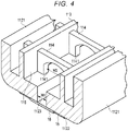
- FIG. 4 is a perspective view schematically illustrating a configuration inside the second case 112.
- FIGS. 5 and 6 are cross-sectional views schematically illustrating a configuration of a nozzle plate 16 used in the thermal head cartridge 1
- FIG. 6 is a cross-sectional view taken along the line VI-VI in FIG. 5 .
- the configuration is illustrated enlarged, reduced or omitted as appropriate.
- the thermal head cartridge 1 is, for example, a liquid ejection head provided in the liquid ejection device 2 such as a recording device illustrated in FIG. 7 .
- the liquid is, for example, ink. That is, the thermal head cartridge 1 is a thermal type inkjet head in which ink in a pressure chamber is heated by a heater to generate bubbles and eject ink.
- the ink as a liquid is, for example, a thermochromic ink containing a reversible thermochromic composition that changes color by heat.
- the thermochromic ink includes not only a discoloring ink that changes color to a different color by heat, but also a decolorizing ink that decolorizes by heat and a color-developing ink that produces color by heat. Decolorization includes the case of changing from a specific color to a transparent color.
- thermochromic ink contains, for example, a color-developing organic compound as a thermochromic composition, an electron-accepting compound, and a reaction medium that determines the temperature at which a color reaction occurs.
- the thermochromic ink is a reversible thermochromic microcapsule pigment in which such a thermochromic composition is encapsulated in microcapsules.
- the thermal head cartridge 1 includes a case 11, a lid 12, a storage body 13, a filter 14, a circuit board 15, and the nozzle plate 16.
- the thermal head cartridge 1 is used, for example, in a posture in which the lid 12 is disposed on the upper side and the nozzle plate 16 is disposed on the lower side.
- the case 11 includes a first case 111 that houses the storage body 13 and the filter 14, the second case 112, a filter holding frame 113, and a single or a plurality of structural members 114.
- a common ink flow path (common liquid flow path) 115 is formed in the second case 112.
- the case 11 is molded from, for example, a resin material.
- the first case 111 is formed in the shape of a bottomed rectangular box formed long in one direction, and the upper portion is open.
- the first case 111 includes two pairs of side walls 1111 formed in a rectangular tubular shape and a bottom wall 1112 formed at one ends of the two pairs of side walls 1111.
- the upper opening of the first case 111 formed by the other ends of the two pairs of side walls 1111 is closed by the lid 12.
- the first case 111 houses the storage body 13 inside.
- the second case 112 is integrally formed at the bottom of the first case 111 on one end side in the longitudinal direction.
- the second case 112 is provided on the bottom wall 1112 of the first case 111, and forms a space continuous with the inside of the first case 111.
- the second case 112 includes two pairs of side walls 1121 and a lower wall 1122 formed at one ends of the two pairs of side walls 1121.
- the two pairs of side walls 1121 are integrally formed with the bottom wall 1112 of the first case 111.
- the lower wall 1122 includes a slit 1123 in which the nozzle plate 16 is provided.
- the slit 1123 is, for example, a unidirectionally long rectangular opening formed in the lower wall 1122.
- the three adjacent side walls 1121 form a side wall integrally formed with the three adjacent side walls 1111 of the first case 111.
- the filter holding frame 113 is formed in a tubular shape, and as a specific example, a rectangular tubular shape.
- the filter holding frame 113 is provided in the second case 112, for example, and is integrally formed with the lower wall 1122.
- the filter holding frame 113 holds the filter 14 at the end (upper end) opposite to the lower wall 1122.
- the filter holding frame 113 is disposed around the slit 1123 formed in the lower wall 1122.
- the structural member 114 is a reinforcing member that reinforces a part of the case 11.
- the number of structural members 114 is appropriately set according to the strength required for the case 11, the material of the case 11, the shape of the case 11, and the like. In the present embodiment, an example in which three structural members 114 are provided is illustrated in FIGS. 2 and 3 .
- the structural members 114 are provided, for example, over the second case 112 and the filter holding frame 113.
- the structural member 114 maintains the shapes of the second case 112 and the filter holding frame 113 by reinforcing the strength of the second case 112 and the filter holding frame 113.
- the second case 112 and the filter holding frame 113 are formed long in the same direction as the longitudinal direction of the first case 111, and the structural member 114 extends along the lateral direction orthogonal to the longitudinal direction of the second case 112 and the filter holding frame 113.
- the structural member 114 includes a notch 1141 at a portion facing the slit 1123 formed in the lower wall 1122 in the filter holding frame 113 of the second case 112.
- the notch 1141 is an opening formed in a portion of the structural member 114 facing the slit 1123.
- the width of the notch 1141 in the extending direction of the structural member 114 is, for example, larger than the width of the slit 1123.
- the notch 1141 has, for example, a U-shape, a rectangular shape, a dome shape, or the like.
- the lateral direction is a direction along the surface direction of the lower wall 1122 and a direction orthogonal to the longitudinal direction of the second case 112 and the filter holding frame 113.
- the lateral direction is a direction orthogonal to the longitudinal direction of the slit 1123, and is an extension direction of the structural member 114.
- the width of the slit 1123 in the lateral direction is W1, and the width of the notch 1141 is W2.
- the width W1 of the slit 1123 is smaller than the width W2 of the notch 1141.
- the common ink flow path 115 is a space in the filter holding frame 113, and is formed by the slit 1123 of the lower wall 1122 of the second case 112 and the notch 1141 of the structural member 114.
- the common ink flow path 115 forms an ink flow path from the filter 14 to the nozzle plate 16. Specifically, in the common ink flow path 115, the slit 1123 is continuous with the nozzle plate 16.
- the width W1 of the slit 1123 is smaller than the width W2 of the notch 1141 and the width of the filter holding frame 113 in the lateral direction. Therefore, the width W2 in the structural member 114 of the common ink flow path 115 is wider than the width W1 in the lower wall 1122 of the second case 112.
- the lid 12 closes the opening of the case 11.
- the lid 12 is integrally fixed to the case 11 by, for example, an adhesive or welding.
- the storage body 13 stores the liquid.
- the storage body 13 is a sponge body such as a sponge capable of storing a liquid.
- the storage body 13 may be a tank for storing the liquid. If the storage body 13 is a tank, the first case 111 may form the storage body 13.
- the filter 14 is held on the filter holding frame 113.
- the filter 14 is provided between the storage body 13 and the filter holding frame 113 of the second case 112.
- the filter 14 supplies the liquid stored in the storage body 13 to the common ink flow path 115 in the filter holding frame 113.
- the circuit board 15 is, for example, a flexible board.
- the circuit board 15 is provided, for example, over the side walls 1111 and 1121 of one of the first case 111 and the second case 112, and the lower wall 1122 of the second case 112.
- a wiring pattern and a terminal portion 151 are mounted on the circuit board 15.
- the circuit board 15 is mounted with the nozzle plate 16 connected to the pattern wiring.
- the nozzle plate 16 is provided, for example, on the lower surface of the second case 112.
- the nozzle plate 16 is disposed to face the slit 1123 of the second case 112.
- the nozzle plate 16 is connected to the common ink flow path 115.
- the nozzle plate 16 includes, for example, a plurality of nozzle holes 161, a plurality of heaters 162, and a plurality of pillars 163.
- the nozzle plate 16 includes a plurality of pressure chambers 164 formed between the nozzle holes 161 and the heaters 162.
- the nozzle plate 16 is provided to face the slit 1123 of the second case 112, and is fluidly connected to the common ink flow path 115.
- the nozzle hole 161 is a hole for injecting a liquid.
- the plurality of nozzle holes 161 are disposed along, for example, the slit 1123 formed in the lower wall 1122 of the second case 112.
- the nozzle plate 16 is provided with two rows of nozzles formed by the plurality of nozzle holes 161.
- the heaters 162 are provided to face the plurality of nozzle holes 161.
- the heater 162 heats the ink existing in the pressure chamber 164 between the heater 162 and the nozzle hole 161 to generate air bubbles.
- the heater 162 ejects ink from the nozzle hole 161 by the generated air bubbles.
- the pillars 163 are provided to face the plurality of pressure chambers 164 between the nozzle holes 161 and the heaters 162.
- the pillar 163 removes air bubbles in the pressure chamber 164 between the nozzle hole 161 and the heater 162.
- the pillar 163 is provided to face the pressure chamber 164 between the nozzle hole 161 and the heater 162.
- a maximum width W3 between the heaters 162 disposed in the lateral direction of the nozzle plate 16 is smaller than the width W2 of the notch 1141. More preferably, a width W4 in the lateral direction between the side surfaces of the pressure chambers 164 arranged in the lateral direction is smaller than the width W2 of the notch 1141.
- the liquid ejection device 2 includes a plurality of thermal head cartridges 1, a head support mechanism 21, a medium support mechanism 22, and a control unit 23.
- the plurality of thermal head cartridges 1 eject, for example, a plurality of different inks.
- the plurality of thermal head cartridges 1 ejects, for example, a thermochromic ink and inks of a plurality of colors, such as cyan ink, magenta ink, yellow ink, black ink, and white ink.
- the characteristics and colors of the ink used for the thermal head cartridge 1 are not limited. Instead of the ink of each color, a transparent glossy ink may be used, or all the thermal head cartridges 1 may be configured to eject ink that discolors, develops color, and decolorizes when irradiated with heat or ultraviolet rays.
- the plurality of thermal head cartridges 1 have the same configuration, although the inks used therein are different from each other, for example.
- the head support mechanism 21 movably supports the thermal head cartridge 1.
- the head support mechanism 21 includes a support member 211 for disposing the plurality of thermal head cartridges 1 in parallel in a predetermined direction, and a guide member 212 for moving the support member 211.
- the support member 211 moves back and forth in one direction by, for example, the guide member 212.
- the guide member 212 is a rail, a guide bar, a belt, or the like that conveys the support member 211 so that the support member 211 moves back and forth.
- the head support mechanism 21 includes a drive source such as a motor for conveying the support member 211.
- the medium support mechanism 22 movably supports a recording medium S.
- the medium support mechanism 22 includes a platen roller 221, a belt, a motor for driving the platen roller 221, and the like, as appropriate, supports sheets of paper as the recording medium S, and moves the sheets along a predetermined transport path.
- the control unit 23 includes, for example, a processor 231, a drive circuit 232 for driving each element, a storage unit 233 that stores various data, and a communication interface 234 for external communication.
- the processor 231 corresponds to the central part of the control unit 23.
- the processor 231 controls each part in order to realize various functions of the liquid ejection device 2 according to the operating system and application programs.
- the circuit board 15 provided in the thermal head cartridge 1 is connected to the processor 231.
- the processor 231 has a function of ejecting ink from the nozzle hole 161 by controlling the operation of the heater 162 provided on the nozzle plate 16 via the circuit board 15.
- the drive circuit 232 generates a drive voltage to be applied to the corresponding heater 162 based on image data, for example, according to the command of the processor 231.
- the storage unit 233 includes, for example, a program memory or RAM.
- the storage unit 233 stores application programs and various setting values.
- the storage unit 233 stores, for example, data such as image data, various setting values such as a voltage value applied to the heater 162, and the like.
- the communication interface 234 receives various information such as a user's input command, a command from an external terminal, data, and a program.
- the processor 231 of the liquid ejection device 2 detects, for example, a printing start command from the outside, the processor 231 controls each configuration as a printing operation.
- the processor 231 controls the medium support mechanism 22 to convey the recording medium S based on the image data stored in the storage unit 233.
- the processor 231 controls the head support mechanism 21 for a back-and-forth motion with respect to the recording medium S, and conveys the thermal head cartridge 1 to the ink ejection position as illustrated by the arrows in FIG. 7 .
- the processor 231 controls the heater 162 so that ink is ejected to the recording medium S from any nozzle hole 161.
- the processor 231 forms an image on the recording medium S by such control.
- the structural member 114 that reinforces the second case 112 and the filter holding frame 113 includes the notch 1141 at a portion facing the slit 1123 of the second case 112.
- the width W2 of the notch 1141 is larger than the width W1 of the slit 1123.
- the width W2 of the notch 1141 is preferably larger than the maximum width W3 between the heaters 162 arranged in the lateral direction, and more preferably larger than the width W4 between the side surfaces of the pressure chamber 164 in the lateral direction.
- the thermal head cartridge 1 can further prevent heat from staying in the common ink flow path 115.
- thermochromic ink As a liquid, it is possible to prevent heat from causing discoloration, decolorization, and color development of the thermochromic ink in the common ink flow path 115.
- the thermal head cartridge 1 and the liquid ejection device 2 of the embodiment described above if the notch 1141 is disposed in the structural member 114 facing the slit 1123, it is possible to prevent the accumulation of heat in the common ink flow path 115.
- the present disclosure is not limited thereto.
- a configuration having a plurality of thermal head cartridges 1 has been described as an example of the liquid ejection device 2, but the present disclosure is not limited thereto.
- the thermal head cartridge 1 may be configured to be used in a mobile printer or a handy printer .
- the thermal head cartridge 1 may be configured to be used alone in a printer.
- thermochromic ink containing a material (composition) having a thermochromic property that discolors, decolorizes, and develops color by heat has been described, but the present disclosure is not limited thereto.
- an ink that discolors, decolorizes, or develops color by light such as ultraviolet rays may be used, or an ink that does not discolor may be used.
- the liquid is not limited to ink, and may be, for example, a chemical solution or the like.
- the thermal head cartridge 1 Since the thermal head cartridge 1 has a configuration capable of minimizing the accumulation of heat in the common liquid flow path, it is preferable to use a liquid that is affected by heat, such as change or deterioration due to heat. However, it goes without saying that the thermal head cartridge 1 can be used for a liquid that is not affected by heat.
- the case 11 is not limited thereto .
- the case 11 may have a configuration in which the second case 112, the filter holding frame 113, and the structural member 114 are integrally molded, and the second case 112 and the first case 111 are molded separately.
- Such the first case 111 and the second case 112 may be integrally assembled by adhesion or welding after molding.
- thermo head cartridge and a liquid ejection device capable of preventing the accumulation of heat in a common liquid flow path.
Landscapes
- Ink Jet (AREA)
- Particle Formation And Scattering Control In Inkjet Printers (AREA)
Abstract
According to one embodiment, a cartridge includes a case (11), a structural member (114), a nozzle plate (16), and a common liquid flow path (115). The structural member (114) is provided in the case (11) and maintains the shape of the case (11) . The nozzle plate (16) is provided in the case (11) and ejects a liquid. The common liquid flow path (115) is formed in the case (11) and the structural member (114), and is continuous with the nozzle plate (16). The common liquid flow path (115) is wider in the structural member (114) than in the case (11).
Description
- Embodiments described herein relate generally to a thermal head cartridge and a liquid ejection device.
- In the related art, a liquid ejection device including a liquid ejection head has been known. A thermal head cartridge which is a thermal type liquid ejection head is known.
- As an ink used for such a liquid ejection head, an ink encapsulated using a reversible thermochromic composition that discolors or decolorizes by heat is also known.
- Such a liquid ejection head includes a common liquid flow path for supplying a liquid to a nozzle. However, since the structural member for maintaining the shape of the liquid ejection head is provided in the common liquid flow path, there is a problem that heat accumulates in the ink in the common liquid flow path. For example, if the temperature of the ink rises in the common liquid flow path, if the ink contains a heat-decoloring type reversible thermochromic composition, when using a thermal head cartridge, there is a risk of causing the ink to decolorize due to heat.
- An objective to be achieved by the present disclosure is to provide a thermal head cartridge and a liquid ejection device capable of minimizing the accumulation of heat in a common liquid flow path.
- In general, according to one embodiment, a cartridge includes a case, a structural member, a nozzle plate, and a common liquid flow path. The structural member is provided in the case and maintains the shape of the case. The nozzle plate is provided in the case and ejects a liquid. The common liquid flow path is formed in the case and the structural member, and is continuous with the nozzle plate. The common liquid flow path is wider in the structural member than in the case.
- According to another embodiment, a plurality of the structural members are provided.
- According to another embodiment, the thermal head cartridge further comprises a storage body that contains the liquid and to which the case is connected.
- According to another embodiment, the thermal head cartridge further comprises a filter that is provided between the storage body and the case.
- According to another embodiment, the thermal head cartridge further comprises a filter holding frame that is provided in the storage body, which covers the periphery of the common liquid flow path and holds the filter.
- According to another embodiment, the liquid is an ink that discolors or decolorizes by heat.
- The present invention further relates to a liquid ejection device comprising the above-mentioned thermal head cartridge and a support mechanism that supports a recording medium that ejects the liquid.
-
-
FIG. 1 is a perspective view schematically illustrating a configuration of a thermal head cartridge according to an embodiment; -
FIG. 2 is a cross-sectional view schematically illustrating a configuration of the thermal head cartridge; -
FIG. 3 is a plan view schematically illustrating a main configuration of a case of the thermal head cartridge; -
FIG. 4 is a perspective view schematically illustrating the main configuration of the case according to the embodiment; -
FIG. 5 is a cross-sectional view schematically illustrating a configuration of a nozzle plate of the thermal head cartridge; -
FIG. 6 is a cross-sectional view illustrating a configuration of the nozzle plate in a cross section taken along the line VI-VI inFIG. 5 ; and -
FIG. 7 is a perspective view schematically illustrating an example of a liquid ejection device using the thermal head cartridge. - Hereinafter, a thermal head cartridge 1 and a
liquid ejection device 2 according to an embodiment will be described with reference toFIGS. 1 to 7 .FIG. 1 is a perspective view schematically illustrating a configuration of the thermal head cartridge 1 according to the embodiment.FIG. 2 is a cross-sectional view schematically illustrating the configuration of the thermal head cartridge 1.FIG. 3 is a plan view illustrating a configuration inside asecond case 112 as a main configuration of acase 11 of the thermal head cartridge 1, andFIG. 4 is a perspective view schematically illustrating a configuration inside thesecond case 112.FIGS. 5 and 6 are cross-sectional views schematically illustrating a configuration of anozzle plate 16 used in the thermal head cartridge 1, andFIG. 6 is a cross-sectional view taken along the line VI-VI inFIG. 5 . For the sake of description in each drawing, the configuration is illustrated enlarged, reduced or omitted as appropriate. - The thermal head cartridge 1 is, for example, a liquid ejection head provided in the
liquid ejection device 2 such as a recording device illustrated inFIG. 7 . In the present embodiment, the liquid is, for example, ink. That is, the thermal head cartridge 1 is a thermal type inkjet head in which ink in a pressure chamber is heated by a heater to generate bubbles and eject ink. - In the present embodiment, the ink as a liquid is, for example, a thermochromic ink containing a reversible thermochromic composition that changes color by heat. Here, the thermochromic ink includes not only a discoloring ink that changes color to a different color by heat, but also a decolorizing ink that decolorizes by heat and a color-developing ink that produces color by heat. Decolorization includes the case of changing from a specific color to a transparent color.
- The thermochromic ink contains, for example, a color-developing organic compound as a thermochromic composition, an electron-accepting compound, and a reaction medium that determines the temperature at which a color reaction occurs. The thermochromic ink is a reversible thermochromic microcapsule pigment in which such a thermochromic composition is encapsulated in microcapsules.
- As illustrated in
FIGS. 1 and2 , the thermal head cartridge 1 includes acase 11, alid 12, astorage body 13, afilter 14, acircuit board 15, and thenozzle plate 16. The thermal head cartridge 1 is used, for example, in a posture in which thelid 12 is disposed on the upper side and thenozzle plate 16 is disposed on the lower side. - The
case 11 includes afirst case 111 that houses thestorage body 13 and thefilter 14, thesecond case 112, afilter holding frame 113, and a single or a plurality ofstructural members 114. In thecase 11, for example, a common ink flow path (common liquid flow path) 115 is formed in thesecond case 112. Thecase 11 is molded from, for example, a resin material. - The
first case 111 is formed in the shape of a bottomed rectangular box formed long in one direction, and the upper portion is open. For example, thefirst case 111 includes two pairs ofside walls 1111 formed in a rectangular tubular shape and abottom wall 1112 formed at one ends of the two pairs ofside walls 1111. The upper opening of thefirst case 111 formed by the other ends of the two pairs ofside walls 1111 is closed by thelid 12. Thefirst case 111 houses thestorage body 13 inside. Thesecond case 112 is integrally formed at the bottom of thefirst case 111 on one end side in the longitudinal direction. - The
second case 112 is provided on thebottom wall 1112 of thefirst case 111, and forms a space continuous with the inside of thefirst case 111. For example, thesecond case 112 includes two pairs ofside walls 1121 and alower wall 1122 formed at one ends of the two pairs ofside walls 1121. The two pairs ofside walls 1121 are integrally formed with thebottom wall 1112 of thefirst case 111. Thelower wall 1122 includes aslit 1123 in which thenozzle plate 16 is provided. Theslit 1123 is, for example, a unidirectionally long rectangular opening formed in thelower wall 1122. The threeadjacent side walls 1121 form a side wall integrally formed with the threeadjacent side walls 1111 of thefirst case 111. - The
filter holding frame 113 is formed in a tubular shape, and as a specific example, a rectangular tubular shape. Thefilter holding frame 113 is provided in thesecond case 112, for example, and is integrally formed with thelower wall 1122. Thefilter holding frame 113 holds thefilter 14 at the end (upper end) opposite to thelower wall 1122. Thefilter holding frame 113 is disposed around theslit 1123 formed in thelower wall 1122. - The
structural member 114 is a reinforcing member that reinforces a part of thecase 11. The number ofstructural members 114 is appropriately set according to the strength required for thecase 11, the material of thecase 11, the shape of thecase 11, and the like. In the present embodiment, an example in which threestructural members 114 are provided is illustrated inFIGS. 2 and3 . - The
structural members 114 are provided, for example, over thesecond case 112 and thefilter holding frame 113. Thestructural member 114 maintains the shapes of thesecond case 112 and thefilter holding frame 113 by reinforcing the strength of thesecond case 112 and thefilter holding frame 113. - For example, the
second case 112 and thefilter holding frame 113 are formed long in the same direction as the longitudinal direction of thefirst case 111, and thestructural member 114 extends along the lateral direction orthogonal to the longitudinal direction of thesecond case 112 and thefilter holding frame 113. Thestructural member 114 includes anotch 1141 at a portion facing theslit 1123 formed in thelower wall 1122 in thefilter holding frame 113 of thesecond case 112. Thenotch 1141 is an opening formed in a portion of thestructural member 114 facing theslit 1123. The width of thenotch 1141 in the extending direction of thestructural member 114 is, for example, larger than the width of theslit 1123. Thenotch 1141 has, for example, a U-shape, a rectangular shape, a dome shape, or the like. - Here, the lateral direction is a direction along the surface direction of the
lower wall 1122 and a direction orthogonal to the longitudinal direction of thesecond case 112 and thefilter holding frame 113. The lateral direction is a direction orthogonal to the longitudinal direction of theslit 1123, and is an extension direction of thestructural member 114. - The width of the
slit 1123 in the lateral direction is W1, and the width of thenotch 1141 is W2. The width W1 of theslit 1123 is smaller than the width W2 of thenotch 1141. - The common
ink flow path 115 is a space in thefilter holding frame 113, and is formed by theslit 1123 of thelower wall 1122 of thesecond case 112 and thenotch 1141 of thestructural member 114. The commonink flow path 115 forms an ink flow path from thefilter 14 to thenozzle plate 16. Specifically, in the commonink flow path 115, theslit 1123 is continuous with thenozzle plate 16. - The width W1 of the
slit 1123 is smaller than the width W2 of thenotch 1141 and the width of thefilter holding frame 113 in the lateral direction. Therefore, the width W2 in thestructural member 114 of the commonink flow path 115 is wider than the width W1 in thelower wall 1122 of thesecond case 112. - The
lid 12 closes the opening of thecase 11. Thelid 12 is integrally fixed to thecase 11 by, for example, an adhesive or welding. - The
storage body 13 stores the liquid. For example, thestorage body 13 is a sponge body such as a sponge capable of storing a liquid. Thestorage body 13 may be a tank for storing the liquid. If thestorage body 13 is a tank, thefirst case 111 may form thestorage body 13. - The
filter 14 is held on thefilter holding frame 113. Thefilter 14 is provided between thestorage body 13 and thefilter holding frame 113 of thesecond case 112. Thefilter 14 supplies the liquid stored in thestorage body 13 to the commonink flow path 115 in thefilter holding frame 113. - The
circuit board 15 is, for example, a flexible board. Thecircuit board 15 is provided, for example, over theside walls first case 111 and thesecond case 112, and thelower wall 1122 of thesecond case 112. For example, a wiring pattern and aterminal portion 151 are mounted on thecircuit board 15. Thecircuit board 15 is mounted with thenozzle plate 16 connected to the pattern wiring. - As illustrated in
FIG. 4 , thenozzle plate 16 is provided, for example, on the lower surface of thesecond case 112. Thenozzle plate 16 is disposed to face theslit 1123 of thesecond case 112. Thenozzle plate 16 is connected to the commonink flow path 115. As illustrated inFIGS. 5 and 6 , thenozzle plate 16 includes, for example, a plurality of nozzle holes 161, a plurality ofheaters 162, and a plurality ofpillars 163. Thenozzle plate 16 includes a plurality ofpressure chambers 164 formed between the nozzle holes 161 and theheaters 162. Thenozzle plate 16 is provided to face theslit 1123 of thesecond case 112, and is fluidly connected to the commonink flow path 115. - The
nozzle hole 161 is a hole for injecting a liquid. The plurality of nozzle holes 161 are disposed along, for example, theslit 1123 formed in thelower wall 1122 of thesecond case 112. For example, thenozzle plate 16 is provided with two rows of nozzles formed by the plurality of nozzle holes 161. - The
heaters 162 are provided to face the plurality of nozzle holes 161. Theheater 162 heats the ink existing in thepressure chamber 164 between theheater 162 and thenozzle hole 161 to generate air bubbles. Theheater 162 ejects ink from thenozzle hole 161 by the generated air bubbles. - The
pillars 163 are provided to face the plurality ofpressure chambers 164 between the nozzle holes 161 and theheaters 162. Thepillar 163 removes air bubbles in thepressure chamber 164 between thenozzle hole 161 and theheater 162. For example, thepillar 163 is provided to face thepressure chamber 164 between thenozzle hole 161 and theheater 162. - For example, a maximum width W3 between the
heaters 162 disposed in the lateral direction of thenozzle plate 16 is smaller than the width W2 of thenotch 1141. More preferably, a width W4 in the lateral direction between the side surfaces of thepressure chambers 164 arranged in the lateral direction is smaller than the width W2 of thenotch 1141. - Next, an example of the
liquid ejection device 2 in which such a thermal head cartridge 1 is used will be described with reference toFIG. 7 . Theliquid ejection device 2 includes a plurality of thermal head cartridges 1, ahead support mechanism 21, amedium support mechanism 22, and acontrol unit 23. - The plurality of thermal head cartridges 1 eject, for example, a plurality of different inks. The plurality of thermal head cartridges 1 ejects, for example, a thermochromic ink and inks of a plurality of colors, such as cyan ink, magenta ink, yellow ink, black ink, and white ink. The characteristics and colors of the ink used for the thermal head cartridge 1 are not limited. Instead of the ink of each color, a transparent glossy ink may be used, or all the thermal head cartridges 1 may be configured to eject ink that discolors, develops color, and decolorizes when irradiated with heat or ultraviolet rays. The plurality of thermal head cartridges 1 have the same configuration, although the inks used therein are different from each other, for example.
- The
head support mechanism 21 movably supports the thermal head cartridge 1. For example, thehead support mechanism 21 includes asupport member 211 for disposing the plurality of thermal head cartridges 1 in parallel in a predetermined direction, and aguide member 212 for moving thesupport member 211. - The
support member 211 moves back and forth in one direction by, for example, theguide member 212. Theguide member 212 is a rail, a guide bar, a belt, or the like that conveys thesupport member 211 so that thesupport member 211 moves back and forth. Thehead support mechanism 21 includes a drive source such as a motor for conveying thesupport member 211. - The
medium support mechanism 22 movably supports a recording medium S. For example, themedium support mechanism 22 includes aplaten roller 221, a belt, a motor for driving theplaten roller 221, and the like, as appropriate, supports sheets of paper as the recording medium S, and moves the sheets along a predetermined transport path. - The
control unit 23 includes, for example, aprocessor 231, adrive circuit 232 for driving each element, astorage unit 233 that stores various data, and acommunication interface 234 for external communication. - The
processor 231 corresponds to the central part of thecontrol unit 23. Theprocessor 231 controls each part in order to realize various functions of theliquid ejection device 2 according to the operating system and application programs. - The
circuit board 15 provided in the thermal head cartridge 1 is connected to theprocessor 231. For example, theprocessor 231 has a function of ejecting ink from thenozzle hole 161 by controlling the operation of theheater 162 provided on thenozzle plate 16 via thecircuit board 15. - The
drive circuit 232 generates a drive voltage to be applied to thecorresponding heater 162 based on image data, for example, according to the command of theprocessor 231. - The
storage unit 233 includes, for example, a program memory or RAM. Thestorage unit 233 stores application programs and various setting values. Thestorage unit 233 stores, for example, data such as image data, various setting values such as a voltage value applied to theheater 162, and the like. - The
communication interface 234 receives various information such as a user's input command, a command from an external terminal, data, and a program. - If the
processor 231 of theliquid ejection device 2 according to the present embodiment detects, for example, a printing start command from the outside, theprocessor 231 controls each configuration as a printing operation. As a specific example, theprocessor 231 controls themedium support mechanism 22 to convey the recording medium S based on the image data stored in thestorage unit 233. Theprocessor 231 controls thehead support mechanism 21 for a back-and-forth motion with respect to the recording medium S, and conveys the thermal head cartridge 1 to the ink ejection position as illustrated by the arrows inFIG. 7 . Then, theprocessor 231 controls theheater 162 so that ink is ejected to the recording medium S from anynozzle hole 161. Theprocessor 231 forms an image on the recording medium S by such control. - According to the
liquid ejection device 2 and the thermal head cartridge 1 of the present embodiment, thestructural member 114 that reinforces thesecond case 112 and thefilter holding frame 113 includes thenotch 1141 at a portion facing theslit 1123 of thesecond case 112. The width W2 of thenotch 1141 is larger than the width W1 of theslit 1123. As a result, theslit 1123 is opened to the space inside thefilter holding frame 113 even at a portion facing thestructural member 114. Therefore, it is possible to prevent theslit 1123 from being blocked by thestructural member 114 and heat from being trapped, and to prevent the accumulation of heat in the commonink flow path 115. - The width W2 of the
notch 1141 is preferably larger than the maximum width W3 between theheaters 162 arranged in the lateral direction, and more preferably larger than the width W4 between the side surfaces of thepressure chamber 164 in the lateral direction. As a result, by making the width of thenotch 1141 larger than that of theheater 162 as a heat source and thepressure chamber 164, the thermal head cartridge 1 can further prevent heat from staying in the commonink flow path 115. - That is, by making the space width of the
notch 1141 of thestructural member 114 larger than the space width in the vicinity of the heat source of thenozzle plate 16, it is possible to prevent heat from being trapped in theslit 1123 communicating with thenozzle plate 16. - If the
liquid ejection device 2 and the thermal head cartridge 1 use a thermochromic ink as a liquid, it is possible to prevent heat from causing discoloration, decolorization, and color development of the thermochromic ink in the commonink flow path 115. - According to the thermal head cartridge 1 and the
liquid ejection device 2 of the embodiment described above, if thenotch 1141 is disposed in thestructural member 114 facing theslit 1123, it is possible to prevent the accumulation of heat in the commonink flow path 115. - Although the example of the embodiment has been described above, the present disclosure is not limited thereto. For example, in the above-described example, a configuration having a plurality of thermal head cartridges 1 has been described as an example of the
liquid ejection device 2, but the present disclosure is not limited thereto. For example, the thermal head cartridge 1 may be configured to be used in a mobile printer or a handy printer . The thermal head cartridge 1 may be configured to be used alone in a printer. - In the above-described example, as an example of the liquid used for the thermal head cartridge 1, an example of a thermochromic ink containing a material (composition) having a thermochromic property that discolors, decolorizes, and develops color by heat has been described, but the present disclosure is not limited thereto. For example, an ink that discolors, decolorizes, or develops color by light such as ultraviolet rays may be used, or an ink that does not discolor may be used. The liquid is not limited to ink, and may be, for example, a chemical solution or the like. Since the thermal head cartridge 1 has a configuration capable of minimizing the accumulation of heat in the common liquid flow path, it is preferable to use a liquid that is affected by heat, such as change or deterioration due to heat. However, it goes without saying that the thermal head cartridge 1 can be used for a liquid that is not affected by heat.
- In the above-described example, an example of integrally molding each configuration with a resin material has been described, but the
case 11 is not limited thereto . For example, thecase 11 may have a configuration in which thesecond case 112, thefilter holding frame 113, and thestructural member 114 are integrally molded, and thesecond case 112 and thefirst case 111 are molded separately. Such thefirst case 111 and thesecond case 112 may be integrally assembled by adhesion or welding after molding. - According to at least one embodiment described above, it is possible to provide a thermal head cartridge and a liquid ejection device capable of preventing the accumulation of heat in a common liquid flow path.
- While certain embodiments have been described, these embodiments have been presented by way of example only, and are not intended to limit the scope of the inventions. Indeed, the novel embodiments described herein may be embodied in a variety of other forms; furthermore, various omissions, substitutions and changes in the form of the embodiments described herein may be made without departing from the spirit of the inventions. The accompanying claims and their equivalents are intended to cover such forms or modifications as would fall within the scope and spirit of the inventions.
Claims (5)
- A thermal head cartridge (1) comprising:a case (11);a structural member (114) that is provided in the case (11)and maintaining a shape of the case (11);a nozzle plate (16) that is provided in the case (11) for injecting a liquid; anda common liquid flow path (115) that is formed in the case (11) and the structural member (114) and continuous with the nozzle plate (16), which is wider in the structural member (114) than in the case (11).
- The cartridge (1) according to claim 1, wherein
a plurality of the structural members (114) are provided. - The cartridge (1) according to any one of claims 1 and 2, further comprising:a storage body (13) that contains the liquid and to which the case (11) is connected;a filter (14) that is provided between the storage body (13) and the case (11); anda filter holding frame (113) that is provided in the storage body (13), which covers the periphery of the common liquid flow path (115) and holds the filter (14).
- The cartridge (1) according to any one of claims 1 to 3, wherein
the liquid is an ink configured to discolor or decolorizes by heat. - A liquid ejection device (2) comprising:the thermal head cartridge (1) according to any one of claims 1 to 4; anda support mechanism (22) that supports a recording medium (S) configured to eject the liquid.
Applications Claiming Priority (1)
| Application Number | Priority Date | Filing Date | Title |
|---|---|---|---|
| JP2021019007A JP7577554B2 (en) | 2021-02-09 | 2021-02-09 | Thermal head cartridge and liquid ejection device |
Publications (1)
| Publication Number | Publication Date |
|---|---|
| EP4039479A1 true EP4039479A1 (en) | 2022-08-10 |
Family
ID=78709205
Family Applications (1)
| Application Number | Title | Priority Date | Filing Date |
|---|---|---|---|
| EP21205856.4A Withdrawn EP4039479A1 (en) | 2021-02-09 | 2021-11-02 | Thermal head cartridge and liquid ejection device |
Country Status (3)
| Country | Link |
|---|---|
| EP (1) | EP4039479A1 (en) |
| JP (1) | JP7577554B2 (en) |
| CN (1) | CN114905854B (en) |
Cited By (1)
| Publication number | Priority date | Publication date | Assignee | Title |
|---|---|---|---|---|
| US20250065637A1 (en) * | 2023-08-25 | 2025-02-27 | Canon Kabushiki Kaisha | Cartridge, cartridge set, and liquid ejection apparatus |
Citations (2)
| Publication number | Priority date | Publication date | Assignee | Title |
|---|---|---|---|---|
| US20090284572A1 (en) * | 2007-02-14 | 2009-11-19 | Tomomi Katoh | Liquid feeding member for liquid ejection head, liquid ejection device, and image forming apparatus |
| US20180170047A1 (en) * | 2016-12-15 | 2018-06-21 | Canon Kabushiki Kaisha | Liquid ejection head |
Family Cites Families (11)
| Publication number | Priority date | Publication date | Assignee | Title |
|---|---|---|---|---|
| JPH0777799B2 (en) * | 1988-12-08 | 1995-08-23 | 日本電気株式会社 | INKJET PRINT HEAD AND METHOD OF MANUFACTURING THE SAME |
| JP3157945B2 (en) * | 1993-03-10 | 2001-04-23 | キヤノン株式会社 | Ink jet recording apparatus and ink jet recording method |
| JP3305041B2 (en) * | 1993-04-30 | 2002-07-22 | キヤノン株式会社 | INK JET HEAD, METHOD OF MANUFACTURING THE SAME AND INK JET DEVICE HAVING THE INK JET HEAD |
| US6386686B1 (en) * | 1998-12-03 | 2002-05-14 | Canon Kabushiki Kaisha | Liquid discharge head, manufacturing method of liquid discharge head, head cartridge, and liquid discharge apparatus |
| KR100850711B1 (en) * | 2005-06-17 | 2008-08-06 | 삼성전자주식회사 | Method and device for temperature control of printer head chip |
| AU2005337424B2 (en) * | 2005-10-10 | 2010-11-18 | Memjet Technology Limited | Low loss electrode connection for inkjet printhead |
| JP4755119B2 (en) | 2007-02-14 | 2011-08-24 | 株式会社リコー | Liquid supply member for liquid discharge head, liquid discharge apparatus, and image forming apparatus |
| US8262204B2 (en) | 2007-10-15 | 2012-09-11 | Hewlett-Packard Development Company, L.P. | Print head die slot ribs |
| KR20100011652A (en) | 2008-07-25 | 2010-02-03 | 삼성전자주식회사 | Inkjet printhead and method of manufacturing the same |
| JP2013129117A (en) * | 2011-12-21 | 2013-07-04 | Sii Printek Inc | Liquid jet head, liquid jet apparatus, and method of manufacturing liquid jet head |
| JP2020063320A (en) | 2018-10-15 | 2020-04-23 | 株式会社パイロットコーポレーション | Reversible thermochromic water-based ink composition for inkjet printer |
-
2021
- 2021-02-09 JP JP2021019007A patent/JP7577554B2/en active Active
- 2021-11-02 EP EP21205856.4A patent/EP4039479A1/en not_active Withdrawn
- 2021-11-08 CN CN202111314667.5A patent/CN114905854B/en active Active
Patent Citations (2)
| Publication number | Priority date | Publication date | Assignee | Title |
|---|---|---|---|---|
| US20090284572A1 (en) * | 2007-02-14 | 2009-11-19 | Tomomi Katoh | Liquid feeding member for liquid ejection head, liquid ejection device, and image forming apparatus |
| US20180170047A1 (en) * | 2016-12-15 | 2018-06-21 | Canon Kabushiki Kaisha | Liquid ejection head |
Cited By (1)
| Publication number | Priority date | Publication date | Assignee | Title |
|---|---|---|---|---|
| US20250065637A1 (en) * | 2023-08-25 | 2025-02-27 | Canon Kabushiki Kaisha | Cartridge, cartridge set, and liquid ejection apparatus |
Also Published As
| Publication number | Publication date |
|---|---|
| CN114905854B (en) | 2024-08-09 |
| CN114905854A (en) | 2022-08-16 |
| JP7577554B2 (en) | 2024-11-05 |
| JP2022121982A (en) | 2022-08-22 |
Similar Documents
| Publication | Publication Date | Title |
|---|---|---|
| JP3419220B2 (en) | Ink jet recording device | |
| JP7799778B2 (en) | Recording device | |
| US8167415B2 (en) | Liquid container | |
| US20220297437A1 (en) | Cartridge | |
| JP4725182B2 (en) | Method for manufacturing liquid supply system and liquid supply system | |
| US8192003B2 (en) | Liquid container and liquid consuming apparatus | |
| EP2165838B1 (en) | Ink cartridge | |
| JP2002264362A (en) | Ink jet recording device | |
| JP7577554B2 (en) | Thermal head cartridge and liquid ejection device | |
| WO2007117036A1 (en) | Liquid container | |
| JP3873675B2 (en) | ink cartridge | |
| WO2003097363A1 (en) | Liquid jet device | |
| JP2005041048A (en) | Liquid ejecting apparatus and liquid container | |
| JP2017140763A (en) | Liquid ejector | |
| JP3991993B2 (en) | Liquid ejector | |
| JP4144644B2 (en) | Liquid ejecting apparatus and valve unit | |
| JP2005199496A (en) | Ink pack, ink cartridge, and ink supply device | |
| JP2002036584A (en) | Printer and head cartridge | |
| JP2004230833A (en) | Ink unit, printing device, printing method, computer system | |
| JP2005288967A (en) | Liquid ejector | |
| JP5470983B2 (en) | Liquid storage container and liquid ejecting apparatus | |
| JP7439386B2 (en) | liquid discharge device | |
| JP4760401B2 (en) | Cap and liquid ejecting apparatus | |
| JP4179152B2 (en) | Liquid discharge cartridge, liquid discharge apparatus, and liquid discharge method | |
| JP2006239900A (en) | Liquid channel assembly and liquid ejecting apparatus |
Legal Events
| Date | Code | Title | Description |
|---|---|---|---|
| PUAI | Public reference made under article 153(3) epc to a published international application that has entered the european phase |
Free format text: ORIGINAL CODE: 0009012 |
|
| STAA | Information on the status of an ep patent application or granted ep patent |
Free format text: STATUS: THE APPLICATION HAS BEEN PUBLISHED |
|
| AK | Designated contracting states |
Kind code of ref document: A1 Designated state(s): AL AT BE BG CH CY CZ DE DK EE ES FI FR GB GR HR HU IE IS IT LI LT LU LV MC MK MT NL NO PL PT RO RS SE SI SK SM TR |
|
| STAA | Information on the status of an ep patent application or granted ep patent |
Free format text: STATUS: THE APPLICATION IS DEEMED TO BE WITHDRAWN |
|
| 18D | Application deemed to be withdrawn |
Effective date: 20230211 |