EP4039454A1 - Compaction system and methods for compacting composite components - Google Patents
Compaction system and methods for compacting composite components Download PDFInfo
- Publication number
- EP4039454A1 EP4039454A1 EP22151476.3A EP22151476A EP4039454A1 EP 4039454 A1 EP4039454 A1 EP 4039454A1 EP 22151476 A EP22151476 A EP 22151476A EP 4039454 A1 EP4039454 A1 EP 4039454A1
- Authority
- EP
- European Patent Office
- Prior art keywords
- noodle
- ring
- section
- cavity
- laminate
- Prior art date
- Legal status (The legal status is an assumption and is not a legal conclusion. Google has not performed a legal analysis and makes no representation as to the accuracy of the status listed.)
- Granted
Links
Images





Classifications
-
- B—PERFORMING OPERATIONS; TRANSPORTING
- B25—HAND TOOLS; PORTABLE POWER-DRIVEN TOOLS; MANIPULATORS
- B25B—TOOLS OR BENCH DEVICES NOT OTHERWISE PROVIDED FOR, FOR FASTENING, CONNECTING, DISENGAGING, OR HOLDING
- B25B11/00—Work holders not covered by any preceding group in the subclass, e.g. magnetic work holders, vacuum work holders
-
- B—PERFORMING OPERATIONS; TRANSPORTING
- B29—WORKING OF PLASTICS; WORKING OF SUBSTANCES IN A PLASTIC STATE IN GENERAL
- B29C—SHAPING OR JOINING OF PLASTICS; SHAPING OF MATERIAL IN A PLASTIC STATE, NOT OTHERWISE PROVIDED FOR; AFTER-TREATMENT OF THE SHAPED PRODUCTS, e.g. REPAIRING
- B29C70/00—Shaping composites, i.e. plastics material comprising reinforcements, fillers or preformed parts, e.g. inserts
- B29C70/04—Shaping composites, i.e. plastics material comprising reinforcements, fillers or preformed parts, e.g. inserts comprising reinforcements only, e.g. self-reinforcing plastics
- B29C70/06—Fibrous reinforcements only
- B29C70/10—Fibrous reinforcements only characterised by the structure of fibrous reinforcements, e.g. hollow fibres
- B29C70/16—Fibrous reinforcements only characterised by the structure of fibrous reinforcements, e.g. hollow fibres using fibres of substantial or continuous length
- B29C70/24—Fibrous reinforcements only characterised by the structure of fibrous reinforcements, e.g. hollow fibres using fibres of substantial or continuous length oriented in at least three directions forming a three-dimensional [3D] structure
-
- B—PERFORMING OPERATIONS; TRANSPORTING
- B30—PRESSES
- B30B—PRESSES IN GENERAL
- B30B11/00—Presses specially adapted for forming shaped articles from material in particulate or plastic state, e.g. briquetting presses, tabletting presses
- B30B11/02—Presses specially adapted for forming shaped articles from material in particulate or plastic state, e.g. briquetting presses, tabletting presses using a ram exerting pressure on the material in a moulding space
- B30B11/027—Particular press methods or systems
-
- B—PERFORMING OPERATIONS; TRANSPORTING
- B29—WORKING OF PLASTICS; WORKING OF SUBSTANCES IN A PLASTIC STATE IN GENERAL
- B29C—SHAPING OR JOINING OF PLASTICS; SHAPING OF MATERIAL IN A PLASTIC STATE, NOT OTHERWISE PROVIDED FOR; AFTER-TREATMENT OF THE SHAPED PRODUCTS, e.g. REPAIRING
- B29C43/00—Compression moulding, i.e. applying external pressure to flow the moulding material; Apparatus therefor
- B29C43/32—Component parts, details or accessories; Auxiliary operations
- B29C43/36—Moulds for making articles of definite length, i.e. discrete articles
- B29C43/361—Moulds for making articles of definite length, i.e. discrete articles with pressing members independently movable of the parts for opening or closing the mould, e.g. movable pistons
-
- B—PERFORMING OPERATIONS; TRANSPORTING
- B29—WORKING OF PLASTICS; WORKING OF SUBSTANCES IN A PLASTIC STATE IN GENERAL
- B29C—SHAPING OR JOINING OF PLASTICS; SHAPING OF MATERIAL IN A PLASTIC STATE, NOT OTHERWISE PROVIDED FOR; AFTER-TREATMENT OF THE SHAPED PRODUCTS, e.g. REPAIRING
- B29C65/00—Joining or sealing of preformed parts, e.g. welding of plastics materials; Apparatus therefor
- B29C65/78—Means for handling the parts to be joined, e.g. for making containers or hollow articles, e.g. means for handling sheets, plates, web-like materials, tubular articles, hollow articles or elements to be joined therewith; Means for discharging the joined articles from the joining apparatus
- B29C65/7802—Positioning the parts to be joined, e.g. aligning, indexing or centring
-
- B—PERFORMING OPERATIONS; TRANSPORTING
- B29—WORKING OF PLASTICS; WORKING OF SUBSTANCES IN A PLASTIC STATE IN GENERAL
- B29C—SHAPING OR JOINING OF PLASTICS; SHAPING OF MATERIAL IN A PLASTIC STATE, NOT OTHERWISE PROVIDED FOR; AFTER-TREATMENT OF THE SHAPED PRODUCTS, e.g. REPAIRING
- B29C66/00—General aspects of processes or apparatus for joining preformed parts
- B29C66/01—General aspects dealing with the joint area or with the area to be joined
- B29C66/05—Particular design of joint configurations
- B29C66/301—Three-dimensional joints, i.e. the joined area being substantially non-flat
-
- B—PERFORMING OPERATIONS; TRANSPORTING
- B29—WORKING OF PLASTICS; WORKING OF SUBSTANCES IN A PLASTIC STATE IN GENERAL
- B29C—SHAPING OR JOINING OF PLASTICS; SHAPING OF MATERIAL IN A PLASTIC STATE, NOT OTHERWISE PROVIDED FOR; AFTER-TREATMENT OF THE SHAPED PRODUCTS, e.g. REPAIRING
- B29C66/00—General aspects of processes or apparatus for joining preformed parts
- B29C66/01—General aspects dealing with the joint area or with the area to be joined
- B29C66/05—Particular design of joint configurations
- B29C66/304—Joining through openings in an intermediate part of the article
-
- B—PERFORMING OPERATIONS; TRANSPORTING
- B29—WORKING OF PLASTICS; WORKING OF SUBSTANCES IN A PLASTIC STATE IN GENERAL
- B29C—SHAPING OR JOINING OF PLASTICS; SHAPING OF MATERIAL IN A PLASTIC STATE, NOT OTHERWISE PROVIDED FOR; AFTER-TREATMENT OF THE SHAPED PRODUCTS, e.g. REPAIRING
- B29C70/00—Shaping composites, i.e. plastics material comprising reinforcements, fillers or preformed parts, e.g. inserts
- B29C70/02—Shaping composites, i.e. plastics material comprising reinforcements, fillers or preformed parts, e.g. inserts comprising combinations of reinforcements, e.g. non-specified reinforcements, fibrous reinforcing inserts and fillers, e.g. particulate fillers, incorporated in matrix material, forming one or more layers and with or without non-reinforced or non-filled layers
- B29C70/021—Combinations of fibrous reinforcement and non-fibrous material
- B29C70/023—Combinations of fibrous reinforcement and non-fibrous material with reinforcing inserts
-
- B—PERFORMING OPERATIONS; TRANSPORTING
- B29—WORKING OF PLASTICS; WORKING OF SUBSTANCES IN A PLASTIC STATE IN GENERAL
- B29C—SHAPING OR JOINING OF PLASTICS; SHAPING OF MATERIAL IN A PLASTIC STATE, NOT OTHERWISE PROVIDED FOR; AFTER-TREATMENT OF THE SHAPED PRODUCTS, e.g. REPAIRING
- B29C70/00—Shaping composites, i.e. plastics material comprising reinforcements, fillers or preformed parts, e.g. inserts
- B29C70/04—Shaping composites, i.e. plastics material comprising reinforcements, fillers or preformed parts, e.g. inserts comprising reinforcements only, e.g. self-reinforcing plastics
- B29C70/28—Shaping operations therefor
- B29C70/54—Component parts, details or accessories; Auxiliary operations, e.g. feeding or storage of prepregs or SMC after impregnation or during ageing
-
- B—PERFORMING OPERATIONS; TRANSPORTING
- B29—WORKING OF PLASTICS; WORKING OF SUBSTANCES IN A PLASTIC STATE IN GENERAL
- B29C—SHAPING OR JOINING OF PLASTICS; SHAPING OF MATERIAL IN A PLASTIC STATE, NOT OTHERWISE PROVIDED FOR; AFTER-TREATMENT OF THE SHAPED PRODUCTS, e.g. REPAIRING
- B29C70/00—Shaping composites, i.e. plastics material comprising reinforcements, fillers or preformed parts, e.g. inserts
- B29C70/04—Shaping composites, i.e. plastics material comprising reinforcements, fillers or preformed parts, e.g. inserts comprising reinforcements only, e.g. self-reinforcing plastics
- B29C70/28—Shaping operations therefor
- B29C70/54—Component parts, details or accessories; Auxiliary operations, e.g. feeding or storage of prepregs or SMC after impregnation or during ageing
- B29C70/541—Positioning reinforcements in a mould, e.g. using clamping means for the reinforcement
-
- B—PERFORMING OPERATIONS; TRANSPORTING
- B29—WORKING OF PLASTICS; WORKING OF SUBSTANCES IN A PLASTIC STATE IN GENERAL
- B29C—SHAPING OR JOINING OF PLASTICS; SHAPING OF MATERIAL IN A PLASTIC STATE, NOT OTHERWISE PROVIDED FOR; AFTER-TREATMENT OF THE SHAPED PRODUCTS, e.g. REPAIRING
- B29C70/00—Shaping composites, i.e. plastics material comprising reinforcements, fillers or preformed parts, e.g. inserts
- B29C70/68—Shaping composites, i.e. plastics material comprising reinforcements, fillers or preformed parts, e.g. inserts by incorporating or moulding on preformed parts, e.g. inserts or layers, e.g. foam blocks
- B29C70/681—Component parts, details or accessories; Auxiliary operations
- B29C70/682—Preformed parts characterised by their structure, e.g. form
-
- B—PERFORMING OPERATIONS; TRANSPORTING
- B29—WORKING OF PLASTICS; WORKING OF SUBSTANCES IN A PLASTIC STATE IN GENERAL
- B29C—SHAPING OR JOINING OF PLASTICS; SHAPING OF MATERIAL IN A PLASTIC STATE, NOT OTHERWISE PROVIDED FOR; AFTER-TREATMENT OF THE SHAPED PRODUCTS, e.g. REPAIRING
- B29C70/00—Shaping composites, i.e. plastics material comprising reinforcements, fillers or preformed parts, e.g. inserts
- B29C70/68—Shaping composites, i.e. plastics material comprising reinforcements, fillers or preformed parts, e.g. inserts by incorporating or moulding on preformed parts, e.g. inserts or layers, e.g. foam blocks
- B29C70/86—Incorporated in coherent impregnated reinforcing layers, e.g. by winding
- B29C70/865—Incorporated in coherent impregnated reinforcing layers, e.g. by winding completely encapsulated
-
- B—PERFORMING OPERATIONS; TRANSPORTING
- B29—WORKING OF PLASTICS; WORKING OF SUBSTANCES IN A PLASTIC STATE IN GENERAL
- B29D—PRODUCING PARTICULAR ARTICLES FROM PLASTICS OR FROM SUBSTANCES IN A PLASTIC STATE
- B29D99/00—Subject matter not provided for in other groups of this subclass
- B29D99/0003—Producing profiled members, e.g. beams
- B29D99/0005—Producing noodles, i.e. composite gap fillers, characterised by their construction
-
- B—PERFORMING OPERATIONS; TRANSPORTING
- B30—PRESSES
- B30B—PRESSES IN GENERAL
- B30B11/00—Presses specially adapted for forming shaped articles from material in particulate or plastic state, e.g. briquetting presses, tabletting presses
- B30B11/02—Presses specially adapted for forming shaped articles from material in particulate or plastic state, e.g. briquetting presses, tabletting presses using a ram exerting pressure on the material in a moulding space
- B30B11/04—Presses specially adapted for forming shaped articles from material in particulate or plastic state, e.g. briquetting presses, tabletting presses using a ram exerting pressure on the material in a moulding space co-operating with a fixed mould
-
- F—MECHANICAL ENGINEERING; LIGHTING; HEATING; WEAPONS; BLASTING
- F01—MACHINES OR ENGINES IN GENERAL; ENGINE PLANTS IN GENERAL; STEAM ENGINES
- F01D—NON-POSITIVE DISPLACEMENT MACHINES OR ENGINES, e.g. STEAM TURBINES
- F01D25/00—Component parts, details, or accessories, not provided for in, or of interest apart from, other groups
- F01D25/28—Supporting or mounting arrangements, e.g. for turbine casing
- F01D25/285—Temporary support structures, e.g. for testing, assembling, installing, repairing; Assembly methods using such structures
-
- F—MECHANICAL ENGINEERING; LIGHTING; HEATING; WEAPONS; BLASTING
- F01—MACHINES OR ENGINES IN GENERAL; ENGINE PLANTS IN GENERAL; STEAM ENGINES
- F01D—NON-POSITIVE DISPLACEMENT MACHINES OR ENGINES, e.g. STEAM TURBINES
- F01D5/00—Blades; Blade-carrying members; Heating, heat-insulating, cooling or antivibration means on the blades or the members
- F01D5/12—Blades
- F01D5/28—Selecting particular materials; Particular measures relating thereto; Measures against erosion or corrosion
- F01D5/282—Selecting composite materials, e.g. blades with reinforcing filaments
-
- F—MECHANICAL ENGINEERING; LIGHTING; HEATING; WEAPONS; BLASTING
- F01—MACHINES OR ENGINES IN GENERAL; ENGINE PLANTS IN GENERAL; STEAM ENGINES
- F01D—NON-POSITIVE DISPLACEMENT MACHINES OR ENGINES, e.g. STEAM TURBINES
- F01D5/00—Blades; Blade-carrying members; Heating, heat-insulating, cooling or antivibration means on the blades or the members
- F01D5/12—Blades
- F01D5/28—Selecting particular materials; Particular measures relating thereto; Measures against erosion or corrosion
- F01D5/284—Selection of ceramic materials
-
- F—MECHANICAL ENGINEERING; LIGHTING; HEATING; WEAPONS; BLASTING
- F01—MACHINES OR ENGINES IN GENERAL; ENGINE PLANTS IN GENERAL; STEAM ENGINES
- F01D—NON-POSITIVE DISPLACEMENT MACHINES OR ENGINES, e.g. STEAM TURBINES
- F01D9/00—Stators
- F01D9/02—Nozzles; Nozzle boxes; Stator blades; Guide conduits, e.g. individual nozzles
- F01D9/04—Nozzles; Nozzle boxes; Stator blades; Guide conduits, e.g. individual nozzles forming ring or sector
- F01D9/042—Nozzles; Nozzle boxes; Stator blades; Guide conduits, e.g. individual nozzles forming ring or sector fixing blades to stators
- F01D9/044—Nozzles; Nozzle boxes; Stator blades; Guide conduits, e.g. individual nozzles forming ring or sector fixing blades to stators permanently, e.g. by welding, brazing, casting or the like
-
- B—PERFORMING OPERATIONS; TRANSPORTING
- B29—WORKING OF PLASTICS; WORKING OF SUBSTANCES IN A PLASTIC STATE IN GENERAL
- B29C—SHAPING OR JOINING OF PLASTICS; SHAPING OF MATERIAL IN A PLASTIC STATE, NOT OTHERWISE PROVIDED FOR; AFTER-TREATMENT OF THE SHAPED PRODUCTS, e.g. REPAIRING
- B29C43/00—Compression moulding, i.e. applying external pressure to flow the moulding material; Apparatus therefor
- B29C43/32—Component parts, details or accessories; Auxiliary operations
- B29C43/36—Moulds for making articles of definite length, i.e. discrete articles
- B29C43/361—Moulds for making articles of definite length, i.e. discrete articles with pressing members independently movable of the parts for opening or closing the mould, e.g. movable pistons
- B29C2043/3613—Moulds for making articles of definite length, i.e. discrete articles with pressing members independently movable of the parts for opening or closing the mould, e.g. movable pistons applying pressure locally
-
- B—PERFORMING OPERATIONS; TRANSPORTING
- B29—WORKING OF PLASTICS; WORKING OF SUBSTANCES IN A PLASTIC STATE IN GENERAL
- B29C—SHAPING OR JOINING OF PLASTICS; SHAPING OF MATERIAL IN A PLASTIC STATE, NOT OTHERWISE PROVIDED FOR; AFTER-TREATMENT OF THE SHAPED PRODUCTS, e.g. REPAIRING
- B29C43/00—Compression moulding, i.e. applying external pressure to flow the moulding material; Apparatus therefor
- B29C43/02—Compression moulding, i.e. applying external pressure to flow the moulding material; Apparatus therefor of articles of definite length, i.e. discrete articles
-
- B—PERFORMING OPERATIONS; TRANSPORTING
- B29—WORKING OF PLASTICS; WORKING OF SUBSTANCES IN A PLASTIC STATE IN GENERAL
- B29C—SHAPING OR JOINING OF PLASTICS; SHAPING OF MATERIAL IN A PLASTIC STATE, NOT OTHERWISE PROVIDED FOR; AFTER-TREATMENT OF THE SHAPED PRODUCTS, e.g. REPAIRING
- B29C70/00—Shaping composites, i.e. plastics material comprising reinforcements, fillers or preformed parts, e.g. inserts
- B29C70/04—Shaping composites, i.e. plastics material comprising reinforcements, fillers or preformed parts, e.g. inserts comprising reinforcements only, e.g. self-reinforcing plastics
- B29C70/28—Shaping operations therefor
- B29C70/30—Shaping by lay-up, i.e. applying fibres, tape or broadsheet on a mould, former or core; Shaping by spray-up, i.e. spraying of fibres on a mould, former or core
- B29C70/34—Shaping by lay-up, i.e. applying fibres, tape or broadsheet on a mould, former or core; Shaping by spray-up, i.e. spraying of fibres on a mould, former or core and shaping or impregnating by compression, i.e. combined with compressing after the lay-up operation
-
- B—PERFORMING OPERATIONS; TRANSPORTING
- B29—WORKING OF PLASTICS; WORKING OF SUBSTANCES IN A PLASTIC STATE IN GENERAL
- B29C—SHAPING OR JOINING OF PLASTICS; SHAPING OF MATERIAL IN A PLASTIC STATE, NOT OTHERWISE PROVIDED FOR; AFTER-TREATMENT OF THE SHAPED PRODUCTS, e.g. REPAIRING
- B29C70/00—Shaping composites, i.e. plastics material comprising reinforcements, fillers or preformed parts, e.g. inserts
- B29C70/04—Shaping composites, i.e. plastics material comprising reinforcements, fillers or preformed parts, e.g. inserts comprising reinforcements only, e.g. self-reinforcing plastics
- B29C70/28—Shaping operations therefor
- B29C70/40—Shaping or impregnating by compression not applied
-
- B—PERFORMING OPERATIONS; TRANSPORTING
- B29—WORKING OF PLASTICS; WORKING OF SUBSTANCES IN A PLASTIC STATE IN GENERAL
- B29C—SHAPING OR JOINING OF PLASTICS; SHAPING OF MATERIAL IN A PLASTIC STATE, NOT OTHERWISE PROVIDED FOR; AFTER-TREATMENT OF THE SHAPED PRODUCTS, e.g. REPAIRING
- B29C70/00—Shaping composites, i.e. plastics material comprising reinforcements, fillers or preformed parts, e.g. inserts
- B29C70/68—Shaping composites, i.e. plastics material comprising reinforcements, fillers or preformed parts, e.g. inserts by incorporating or moulding on preformed parts, e.g. inserts or layers, e.g. foam blocks
- B29C70/82—Forcing wires, nets or the like partially or completely into the surface of an article, e.g. by cutting and pressing
-
- B—PERFORMING OPERATIONS; TRANSPORTING
- B29—WORKING OF PLASTICS; WORKING OF SUBSTANCES IN A PLASTIC STATE IN GENERAL
- B29D—PRODUCING PARTICULAR ARTICLES FROM PLASTICS OR FROM SUBSTANCES IN A PLASTIC STATE
- B29D99/00—Subject matter not provided for in other groups of this subclass
- B29D99/0003—Producing profiled members, e.g. beams
-
- B—PERFORMING OPERATIONS; TRANSPORTING
- B29—WORKING OF PLASTICS; WORKING OF SUBSTANCES IN A PLASTIC STATE IN GENERAL
- B29D—PRODUCING PARTICULAR ARTICLES FROM PLASTICS OR FROM SUBSTANCES IN A PLASTIC STATE
- B29D99/00—Subject matter not provided for in other groups of this subclass
- B29D99/0025—Producing blades or the like, e.g. blades for turbines, propellers, or wings
-
- B—PERFORMING OPERATIONS; TRANSPORTING
- B29—WORKING OF PLASTICS; WORKING OF SUBSTANCES IN A PLASTIC STATE IN GENERAL
- B29L—INDEXING SCHEME ASSOCIATED WITH SUBCLASS B29C, RELATING TO PARTICULAR ARTICLES
- B29L2031/00—Other particular articles
- B29L2031/08—Blades for rotors, stators, fans, turbines or the like, e.g. screw propellers
-
- B—PERFORMING OPERATIONS; TRANSPORTING
- B29—WORKING OF PLASTICS; WORKING OF SUBSTANCES IN A PLASTIC STATE IN GENERAL
- B29L—INDEXING SCHEME ASSOCIATED WITH SUBCLASS B29C, RELATING TO PARTICULAR ARTICLES
- B29L2031/00—Other particular articles
- B29L2031/748—Machines or parts thereof not otherwise provided for
- B29L2031/7504—Turbines
-
- B—PERFORMING OPERATIONS; TRANSPORTING
- B32—LAYERED PRODUCTS
- B32B—LAYERED PRODUCTS, i.e. PRODUCTS BUILT-UP OF STRATA OF FLAT OR NON-FLAT, e.g. CELLULAR OR HONEYCOMB, FORM
- B32B3/00—Layered products comprising a layer with external or internal discontinuities or unevennesses, or a layer of non-planar shape; Layered products comprising a layer having particular features of form
- B32B3/02—Layered products comprising a layer with external or internal discontinuities or unevennesses, or a layer of non-planar shape; Layered products comprising a layer having particular features of form characterised by features of form at particular places, e.g. in edge regions
- B32B3/08—Layered products comprising a layer with external or internal discontinuities or unevennesses, or a layer of non-planar shape; Layered products comprising a layer having particular features of form characterised by features of form at particular places, e.g. in edge regions characterised by added members at particular parts
-
- F—MECHANICAL ENGINEERING; LIGHTING; HEATING; WEAPONS; BLASTING
- F05—INDEXING SCHEMES RELATING TO ENGINES OR PUMPS IN VARIOUS SUBCLASSES OF CLASSES F01-F04
- F05D—INDEXING SCHEME FOR ASPECTS RELATING TO NON-POSITIVE-DISPLACEMENT MACHINES OR ENGINES, GAS-TURBINES OR JET-PROPULSION PLANTS
- F05D2230/00—Manufacture
- F05D2230/20—Manufacture essentially without removing material
-
- F—MECHANICAL ENGINEERING; LIGHTING; HEATING; WEAPONS; BLASTING
- F05—INDEXING SCHEMES RELATING TO ENGINES OR PUMPS IN VARIOUS SUBCLASSES OF CLASSES F01-F04
- F05D—INDEXING SCHEME FOR ASPECTS RELATING TO NON-POSITIVE-DISPLACEMENT MACHINES OR ENGINES, GAS-TURBINES OR JET-PROPULSION PLANTS
- F05D2240/00—Components
- F05D2240/10—Stators
- F05D2240/11—Shroud seal segments
-
- F—MECHANICAL ENGINEERING; LIGHTING; HEATING; WEAPONS; BLASTING
- F05—INDEXING SCHEMES RELATING TO ENGINES OR PUMPS IN VARIOUS SUBCLASSES OF CLASSES F01-F04
- F05D—INDEXING SCHEME FOR ASPECTS RELATING TO NON-POSITIVE-DISPLACEMENT MACHINES OR ENGINES, GAS-TURBINES OR JET-PROPULSION PLANTS
- F05D2300/00—Materials; Properties thereof
- F05D2300/60—Properties or characteristics given to material by treatment or manufacturing
- F05D2300/603—Composites; e.g. fibre-reinforced
- F05D2300/6033—Ceramic matrix composites [CMC]
Definitions
- a volume of air 58 enters the turbofan 10 through an associated inlet 60 of the nacelle 50 and/or fan section 14.
- a first portion of the air 58 as indicated by arrows 62 is directed or routed into the bypass airflow passage 56 and a second portion of the air 58 as indicated by arrow 64 is directed or routed into the annular core inlet 20 and into the LP compressor 22.
- the pressure of the second portion of air 64 is then increased as it is routed through the high pressure (HP) compressor 24 and into the combustion section 26, where it is mixed with fuel and burned to provide combustion gases 66.
- HP high pressure
- a noodle insertion tool can be mounted to the plunger 150 of the compaction system 100 of FIG. 9 .
- a chuck of the plunger 150 can hold the noodle insertion tool.
- the noodle can be mounted to the noodle insertion tool.
- the plunger 150 can be controlled to move toward the laminate 200 along the first direction D1 by the controller 192.
- the noodle insertion tool can position the noodle 230 relative to the cavity 220.
Landscapes
- Engineering & Computer Science (AREA)
- Mechanical Engineering (AREA)
- Chemical & Material Sciences (AREA)
- Composite Materials (AREA)
- General Engineering & Computer Science (AREA)
- Materials Engineering (AREA)
- Ceramic Engineering (AREA)
- Textile Engineering (AREA)
- Manufacturing And Processing Devices For Dough (AREA)
Abstract
Description
- The present subject matter relates generally to compaction systems and methods of compacting composite components, such as composite components for gas turbine engines.
- Some gas turbine engines can include a number of different types of composite components, such as Ceramic Matrix Composite (CMC) components and Polymer Matrix Composite (PMC) components. In the process of manufacturing such composite components, and composite components generally, there is often a need to compact the components. Conventional manufacturing methods, such as a vacuum/ positive pressure debulk methods and press methods, have been effective for compacting composite components. However, conventional methods usually require complex equipment and tool moving solutions. Additionally, they can be cumbersome and imprecise in the way they apply pressure to the component.
- Accordingly, improved compaction systems and methods of compacting composite components that address one or more of the challenges noted above would be useful.
- Aspects and advantages of the invention will be set forth in part in the following description, or may be obvious from the description, or may be learned through practice of the invention.
- In one aspect, a method is provided. The method includes positioning a laminate formed of plies on a tool of a compaction system. The laminate defines a cavity. The method also includes positioning a noodle relative to or in the cavity. Further, the method includes positioning a noodle ring relative to the noodle. In addition, the method includes moving a plunger to apply a force on the noodle ring so that the noodle ring compacts the noodle into the cavity.
- In another aspect, a method is provided. The method includes positioning a laminate on a tool of a compaction system. The laminate has a first section and a second section each formed of one or more plies. Further, the laminate defines a cavity at a location where the first section and the second section diverge. The method also includes positioning at least a portion of a noodle in the cavity. Further, the method includes positioning a noodle ring relative to the noodle, the noodle ring having a cross section shaped complementary to a cross section of the noodle. In addition, the method includes moving a plunger to apply a force on the noodle ring so that the noodle ring compacts the noodle into the cavity.
- In yet another aspect, a method is provided. The method includes positioning a laminate on a tool of a compaction system, the laminate defining a cavity. In addition, the method includes positioning at least a portion of a noodle in the cavity and positioning a noodle ring relative to the noodle. Further, the method includes coupling the noodle ring to the tool. The method also includes applying a force on the noodle ring so that the noodle is compacted into the cavity.
- These and other features, aspects and advantages of the present invention will become better understood with reference to the following description and appended claims. The accompanying drawings, which are incorporated in and constitute a part of this specification, illustrate embodiments of the invention and, together with the description, serve to explain the principles of the invention.
- A full and enabling disclosure of the present invention, including the best mode thereof, directed to one of ordinary skill in the art, is set forth in the specification, which makes reference to the appended figures, in which:
-
FIG. 1 provides a schematic cross-sectional view of an exemplary gas turbine engine according to various embodiments of the present subject matter; -
FIG. 2 provides a perspective view of a turbine nozzle segment according to an exemplary embodiment of the present subject matter; -
FIG. 3 provides a schematic cross-sectional view of a compaction system in the process of compacting a laminate according to an example embodiment of the present subject matter; -
FIG. 4 provides a perspective view of an example noodle ring positioned relative to a noodle according to an example embodiment of the present subject matter; -
FIG. 5 provides a perspective view of another example noodle ring positioned relative to a noodle according to an example embodiment of the present subject matter; -
FIG. 6 provides a schematic cross-sectional view of another compaction system in the process of compacting a laminate according to an example embodiment of the present subject matter; -
FIG. 7 provides a schematic cross-sectional view of yet another compaction system in the process of compacting a laminate according to an example embodiment of the present subject matter; -
FIG. 8 provides a schematic cross-sectional view of a further compaction system in the process of compacting a laminate according to an example embodiment of the present subject matter; -
FIG. 9 provides a schematic cross-sectional view of a further compaction system in the process of compacting a laminate according to an example embodiment of the present subject matter; and -
FIG. 10 provides a flow diagram of a method of compacting a laminate according to one example embodiment of the present subject matter; -
FIG. 11 provides a schematic cross-sectional view of a compaction system in the process of shaping a cavity of a laminate to a desired shape according to one example embodiment of the present subject matter; and -
FIG. 12 provides a schematic view of a computing system for implementing one or more aspects of the present disclosure according to example embodiments of the present subject matter. - Repeat use of reference characters in the present specification and drawings is intended to represent the same or analogous features or elements.
- Reference will now be made in detail to present embodiments of the invention, one or more examples of which are illustrated in the accompanying drawings. The detailed description uses numerical and letter designations to refer to features in the drawings. Like or similar designations in the drawings and description have been used to refer to like or similar parts of the invention. As used herein, the terms "first," "second," and "third" may be used interchangeably to distinguish one component from another and are not intended to signify location or importance of the individual components. The terms "upstream" and "downstream" refer to the relative direction with respect to fluid flow in a fluid pathway. For example, "upstream" refers to the direction from which the fluid flows and "downstream" refers to the direction to which the fluid flows.
- Approximating language, as used herein throughout the specification and claims, is applied to modify any quantitative representation that could permissibly vary without resulting in a change in the basic function to which it is related. Accordingly, a value modified by a term or terms, such as "about", "approximately", and "substantially", are not to be limited to the precise value specified. For example, the approximating language may refer to being within a 1, 2, 4, 5, 10, 15, or 20 percent margin in either individual values, range(s) of values, and/or endpoints defining range(s) of values.
- Exemplary aspects of the present disclosure are directed to compaction systems and methods of compacting components, such as composite components for gas turbine engines. In one aspect, a method is provided for compacting a laminate. The laminate can form an entire portion of a composite component or a portion thereof. The laminate can be laid up on a tool of a compaction system or can be laid up elsewhere and subsequently positioned on the tool. The laminate is laid up in such a way that the laminate defines a cavity. The cavity can be a space between two diverging sections of the laminate, for example. With the laminate positioned on the tool, a noodle is positioned relative to or in the cavity. Generally, the noodle fills the cavity to improve the mechanical properties of a finished component. In some embodiments, prior to positioning the noodle relative to the cavity, a shaping tool can be moved into the cavity to shape the cavity to a desired shape. This may ensure the cavity is sized to receive the noodle.
- With the noodle positioned relative to or in the cavity, a noodle ring is positioned relative to the noodle. For instance, the noodle ring can be placed over the noodle. A cross section of the noodle ring can be shaped complementary to a cross section of the noodle. For instance, if the noodle has a cross section with an airfoil shape, the noodle ring can likewise have a cross section with the same airfoil shape. The noodle ring can have a hollow interior, a look-through window, or can be transparent in whole or in part. In this way, when an operator is positioning the noodle ring relative to the noodle, the operator is able to visibly see the plies of the laminate and can take care not to damage the plies. In some embodiments, optionally, a sheet or film is placed between the noodle and the noodle ring.
- With the noodle ring positioned in place, a plunger of the compaction system is moved so that it engages the noodle ring. Particularly, the plunger is moved in such a way that a force is applied on the noodle ring so that the noodle ring compacts the noodle into the cavity. Any suitable mechanical device, mechanism, or system can be used to move the plunger so that the noodle is ultimately compacted into the cavity. In addition to compacting the noodle into the cavity, the laminate or portions thereof can likewise be compacted when the plunger is moved during the compaction process.
- The compaction systems and methods provided herein provide a number of advantages and benefits. For instance, the systems and methods provided herein allow for compaction of a component with minimal equipment and tool transportation, offering decreased process time and leaner processes, among other benefits. Further, the systems and methods provided herein provide the ability to apply pressure to specific portions of a laminate only, e.g., compacting a noodle into a cavity of a laminate. This may allow for improved compaction/composite part assembly and increased part yield. In addition, compaction of a composite component using the systems and methods disclosed herein can be more closely controlled than with conventional systems and techniques, such as bagging. For instance, the systems and methods provided herein can compact components with precise load or displacement-controlled compaction.
-
FIG. 1 provides a schematic cross-sectional view of a gas turbine engine in accordance with one example embodiment of the present subject matter. For the depicted embodiment ofFIG. 1 , the gas turbine engine is a high-bypassturbofan jet engine 10, referred to herein as "turbofan 10." As shown inFIG. 1 , theturbofan 10 defines an axial direction A (extending parallel to alongitudinal centerline 12 provided for reference), a radial direction R, and a circumferential direction extending in a plane orthogonal to the axial direction A three hundred sixty degrees around thelongitudinal centerline 12. - The
turbofan 10 includes afan section 14 and acore turbine engine 16 disposed downstream from thefan section 14. Thecore turbine engine 16 includes a substantially tubularouter casing 18 that defines anannular core inlet 20. Theouter casing 18 encases, in serial flow relationship, a compressor section including a booster or low pressure (LP)compressor 22 and a high pressure (HP)compressor 24; acombustion section 26; a turbine section including a high pressure (HP)turbine 28 and a low pressure (LP)turbine 30; and a jetexhaust nozzle section 32. A high pressure (HP) shaft orspool 34 drivingly connects theHP turbine 28 to theHP compressor 24. A low pressure (LP) shaft or spool 36 drivingly connects theLP turbine 30 to theLP compressor 22. - The
fan section 14 includes avariable pitch fan 38 having a plurality offan blades 40 coupled to adisk 42 in a spaced apart manner. As depicted, thefan blades 40 extend outward from thedisk 42 generally along the radial direction R. Eachfan blade 40 is rotatable relative to thedisk 42 about a pitch axis P by virtue of thefan blades 40 being operatively coupled to asuitable actuation member 44 configured to collectively vary the pitch of thefan blades 40 in unison. Thefan blades 40,disk 42, andactuation member 44 are together rotatable about thelongitudinal axis 12 by LP shaft 36. - Referring still to
FIG. 1 , thedisk 42 is covered by arotatable front nacelle 48 aerodynamically contoured to promote an airflow through the plurality offan blades 40. Additionally, thefan section 14 includes an annular fan casing orouter nacelle 50 that circumferentially surrounds thefan 38 and/or at least a portion of thecore turbine engine 16. Thenacelle 50 may be supported relative to thecore turbine engine 16 by a plurality of circumferentially-spaced outlet guide vanes 52. Moreover, adownstream section 54 of thenacelle 50 may extend over an outer portion of thecore turbine engine 16 so as to define abypass airflow passage 56 therebetween. - During operation of the
turbofan 10, a volume ofair 58 enters theturbofan 10 through an associated inlet 60 of thenacelle 50 and/orfan section 14. As the volume ofair 58 passes across thefan blades 40, a first portion of theair 58 as indicated byarrows 62 is directed or routed into thebypass airflow passage 56 and a second portion of theair 58 as indicated byarrow 64 is directed or routed into theannular core inlet 20 and into theLP compressor 22. The pressure of the second portion ofair 64 is then increased as it is routed through the high pressure (HP)compressor 24 and into thecombustion section 26, where it is mixed with fuel and burned to providecombustion gases 66. - The
combustion gases 66 are routed through theHP turbine 28 where a portion of thermal and/or kinetic energy from thecombustion gases 66 is extracted via sequential stages of HP turbine stator vanes 68 that are coupled to theouter casing 18 and HPturbine rotor blades 70 that are coupled to the HP shaft orspool 34, thus causing the HP shaft orspool 34 to rotate, thereby supporting operation of theHP compressor 24. Thecombustion gases 66 are then routed through theLP turbine 30 where a second portion of thermal and kinetic energy is extracted from thecombustion gases 66 via sequential stages of LPturbine stator vanes 72 that are coupled to theouter casing 18 and LPturbine rotor blades 74 that are coupled to the LP shaft or spool 36, thus causing the LP shaft or spool 36 to rotate, thereby supporting operation of theLP compressor 22 and/or rotation of thefan 38. - The
combustion gases 66 are subsequently routed through the jetexhaust nozzle section 32 of thecore turbine engine 16 to provide propulsive thrust. Simultaneously, the pressure of the first portion ofair 62 is substantially increased as the first portion ofair 62 is routed through thebypass airflow passage 56 before it is exhausted from a fannozzle exhaust section 76 of theturbofan 10, also providing propulsive thrust. TheHP turbine 28, theLP turbine 30, and the jetexhaust nozzle section 32 at least partially define ahot gas path 78 for routing thecombustion gases 66 through thecore turbine engine 16. - It will be appreciated that, although described with respect to
turbofan 10 havingcore turbine engine 16, the present subject matter may be applicable to other types of turbomachinery. For example, the present subject matter may be suitable for use with or in turboprops, turboshafts, turbojets, industrial and marine gas turbine engines, and/or auxiliary power units. - In some embodiments, components of
turbofan 10 can be formed of a composite material. For example, components withinhot gas path 78, such as components ofcombustion section 26,HP turbine 28, and/orLP turbine 30, can be formed of a Ceramic Matrix Composite (CMC) material, which is a non-metallic material having high temperature capability. For instance, turbine blades and turbine nozzles can be formed of CMC materials. Other components ofturbine engine 10 also may be formed from CMC materials or other suitable composite materials, such as e.g., a Polymer Matrix Composite (PMC) material. - Exemplary matrix materials for such CMC components can include silicon carbide, silicon, silica, alumina, or combinations thereof. Ceramic fibers can be embedded within the matrix, such as oxidation stable reinforcing fibers including monofilaments like sapphire and silicon carbide (e.g., Textron's SCS-6), as well as rovings and yarn including silicon carbide (e.g., Nippon Carbon's NICALON®, Ube Industries' TYRANNO®, and Dow Corning's SYLRAMIC®), alumina silicates (e.g., Nextel's 440 and 480), and chopped whiskers and fibers (e.g., Nextel's 440 and SAFFIL®), and optionally ceramic particles (e.g., oxides of Si, Al, Zr, Y, and combinations thereof) and inorganic fillers (e.g., pyrophyllite, wollastonite, mica, talc, kyanite, and montmorillonite). CMC materials may have coefficients of thermal expansion in the range of about 1.3×10⁻⁶ in/in/°F to about 3.5×10⁻⁶ in/in/°F in a temperature range of approximately 1000-1200° F.
-
FIG. 2 provides a perspective view of aturbine nozzle segment 80 according to an exemplary embodiment of the present subject matter. For this embodiment, theturbine nozzle segment 80 is formed of a CMC material, such as one or more of the CMC materials noted above. Theturbine nozzle segment 80 is one of a number of nozzle segments that when connected together form an annular nozzle assembly of a gas turbine engine, such as e.g., theturbofan 10 ofFIG. 1 . Thenozzle segment 80 includesvanes 82, such as e.g., stator vanes 68 of theturbofan 10 ofFIG. 1 . Eachvane 82 or airfoil extends between an outer andinner band vanes 82 define a plurality of cooling holes 88. Cooling holes 88 provide film cooling to improve the thermal capability of thevanes 82. The cooling holes 88 can be fluidly connected to one or more fluid passageways that extend internally through thevanes 82. Furthermore, as will be explained more fully below, one or more portions of theturbine nozzle segment 80 can be subjected to a compaction process. -
FIG. 3 provides a schematic cross-sectional view of acompaction system 100 in the process of compacting a laminate 200 according to one example embodiment of the present subject matter. The laminate 200 can form a portion of a composite component, such as theturbine nozzle segment 80 ofFIG. 2 . It will be appreciated that thecompaction system 100 can be used to compact laminates of other components as well. - For the depicted embodiment of
FIG. 3 , the laminate 200 has afirst section 210 and asecond section 212. Thefirst section 210 includes one ormore plies 214 and thesecond section 212 includes one or more plies 216. Generally, thefirst section 210 extends lengthwise along a first direction D1, e.g., a radial direction. At least a portion of thesecond section 212 extends lengthwise along the first direction D1 and at least a portion of thesecond section 212 extends lengthwise along a second direction D2, e.g., a circumferential direction. Accordingly, thesecond section 212 of the laminate 200 transitions from extending lengthwise along the first direction D1 to extending lengthwise along the second direction D2. The second direction D2 can be substantially orthogonal to the first direction D1. - The
second section 212 transitions from extending lengthwise along the first direction D1 to the second direction D2 at ajoint interface 218 of the laminate 200. As one example, thejoint interface 218 of the laminate may correspond with the joint interface between one of thevanes 82 and theouter band 84 of theturbine nozzle segment 80 ofFIG. 2 . For instance, the portion of thesecond section 212 that extends lengthwise along the second direction D2 may form theouter band 84 or a portion thereof. Thefirst section 210 and the portion of thesecond section 212 that extends lengthwise along the first direction D1 may form one of thevanes 82 or a portion thereof. As another example, thejoint interface 218 of the laminate may correspond with the joint interface between one of thevanes 82 and theinner band 86 of theturbine nozzle segment 80 ofFIG. 2 . - The laminate 200 defines a
cavity 220. For this embodiment, thecavity 220 is defined between thefirst section 210 and thesecond section 212 where thesecond section 212 transitions from extending lengthwise along the first direction D1 to extending lengthwise along the second direction D2, or stated another way, at thejoint interface 218. In this regard, the laminate 200 defines thecavity 220 at a location where thefirst section 210 and thesecond section 212 diverge. Thecavity 220 has a triangular cross section in this example embodiment, but it will be appreciated that thecavity 220 may be defined to have other suitable cross-sectional shapes. Anoodle 230 can be positioned in or relative to thecavity 220 and compacted therein by thecompaction system 100 as will be described herein. Thenoodle 230 can be formed of a composite material, such as a CMC material. Thenoodle 230 can be formed of other suitable materials as well. Thenoodle 230 can be formed as a single part or can be formed as separate or distinct parts. Generally, thenoodle 230 is positioned within thecavity 220 to fill the void, which provides improved mechanical properties to the finished component, among other benefits. In some embodiments, a slurry composition, e.g., a matrix material, can be inserted into thecavity 220 prior to thenoodle 230 being compacted into thecavity 220. This may facilitate a more complete filling of thecavity 220, which may lead to improved mechanical properties of the finished component. - As further shown in
FIG. 3 , thecompaction system 100 includes atool holder 110 that holds or supports atool 112. Thetool 112 is contoured complementary to the shape of the laminate 200 so that the laminate 200 can be properly positioned in place for compaction. As depicted, the laminate 200 can be positioned relative to or placed over thetool 112. When the laminate 200 is positioned in place on thetool 112, anoodle ring 120 is positioned relative to thenoodle 230. Particularly, thenoodle ring 120 is placed over at least a portion of thenoodle 230. Thenoodle ring 120 can be formed as a single part or can be formed as separate or distinct sections. Thus, in some embodiments, thenoodle ring 120 is formed of a single, unitary component. In other embodiments, thenoodle ring 120 is formed of at least two sections. - In some embodiments, the
noodle ring 120 provides some means for an operator to look through thenoodle ring 120. In this way, when an operator is placing thenoodle ring 120 in position relative to thenoodle 230, the operator can look through thenoodle 230 and can visibly see a protrudingportion 222 of thefirst section 210. The protrudingportion 222 is the portion of thefirst section 210 that protrudes above thesecond section 212 andnoodle 230 along the first direction D1 as illustrated inFIG. 3 . As shown, when thenoodle ring 120 is in place, the protrudingportion 222 of thefirst section 210 of the laminate 200 overlaps with thenoodle ring 120 along the first direction D1. With the protrudingportion 222 of thefirst section 210 located, the operator can make sure not to contact the protrudingportion 222 with thenoodle ring 120 and can position thenoodle ring 120 relative to thenoodle 230 as shown inFIG. 3 . If contacted, theplies 214 forming the protrudingportion 222 of thefirst section 210 can become damaged, e.g., delamination can occur. - In some embodiments, the
noodle ring 120 can define ahollow interior 122, e.g., as shown inFIG. 3 . Thehollow interior 122 allows an operator to look through thenoodle ring 120 to ensure the protrudingportion 222 of thefirst section 210 is not contacted when thenoodle ring 120 is positioned in place. In other embodiments, thenoodle ring 120 or a portion thereof can be formed of a transparent material. For instance, in some embodiments, thenoodle ring 120 can include a look-through window. In other embodiments, theentire noodle ring 120 can be formed of a transparent material. - The
noodle ring 120 can be shaped complementary to thenoodle 230. Particularly, thenoodle ring 120 can have a cross section shaped complementary to a cross section of thenoodle 230. Stated another way, an outline of thenoodle ring 120 can be shaped complementary to an outline of thenoodle 230. In this way, when a force is applied to thenoodle ring 120 during compaction, thenoodle ring 120 can apply a force on theentire noodle 230 during compaction. -
FIG. 4 provides a perspective view of anexample noodle ring 120 positioned relative to a noodle (the noodle is not shown inFIG. 4 ). InFIG. 4 , a plunger of thecompaction system 100 is shown transparent for illustrative purposes. As depicted, thenoodle ring 120 has a cross section shaped like an airfoil or vane, such as avane 82 of theturbine nozzle segment 80 ofFIG. 2 . The cross-sectional shape of thenoodle ring 120 can match or be complementary to the cross-sectional shape of the noodle, which is positioned below thenoodle ring 120 and not visible inFIG. 4 . -
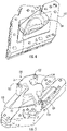
FIG. 5 provides a perspective view of anotherexample noodle ring 120 positioned relative to a noodle (the noodle is not shown inFIG. 5 ). For this embodiment, thenoodle ring 120 has amain body 124. Themain body 124 has a cross section shaped complementary to a cross section of the noodle, which is positioned below thenoodle ring 120 and not visible inFIG. 5 . Moreover, for this embodiment, thenoodle ring 120 has a first stabilizingmember 126 extending outward from themain body 124. The first stabilizingmember 126 couples thenoodle ring 120 to at least one of a band debulk cap (not shown inFIG. 5 ) and thetool 112. Thenoodle ring 120 also has a second stabilizingmember 128 extending outward from themain body 124. The second stabilizingmember 128 couples thenoodle ring 120 to at least one of a band debulk cap (not shown inFIG. 5 ) and thetool 112. The first stabilizingmember 126 and the second stabilizingmember 128 extend outward from themain body 124 in opposite directions from one another. However, in other embodiments, the first stabilizingmember 126 and the second stabilizingmember 128 need not extend in opposite directions from one another. - The first stabilizing
member 126 defines one ormore openings 127 that are sized to receive fasteners, such as threaded bolts. Threaded bolts can extend through the first stabilizingmember 126 and into corresponding threaded openings defined by thetool 112, for example. Similarly, the second stabilizingmember 128 defines one ormore openings 129 that are sized to receive fasteners, such as threaded bolts. Threaded bolts can extend through the second stabilizingmember 128 and into corresponding threaded openings defined by thetool 112, for example. Such bolts or other fasteners can be used to secure thenoodle ring 120 to thetool 112, which may ensure that thenoodle ring 120 remains in place during compaction. In this manner, thenoodle ring 120 can be coupled to thetool 112. Using the first and second stabilizingmembers main body 124 of thenoodle ring 120 on opposing sides thereof can provide enhanced stability to thenoodle ring 120 during compaction. - Returning to
FIG. 3 , with thenoodle ring 120 positioned in place relative to thenoodle 230, optionally, aband debulk cap 130 can be moved in place to secure thenoodle ring 120 in place relative to thenoodle 230 as shown inFIG. 3 . Alatch system 140 can be used to secure theband debulk cap 130 in place. For this embodiment, thelatch system 140 includes latch clamps 142 that connect with thetool holder 110. Eachlatch clamp 142 is movable between a clamped position and an unclamped position. In the clamped position, a givenlatch clamp 142 secures theband debulk cap 130 in place. In the unclamped position, a givenlatch clamp 142 does not secure theband debulk cap 130 in place. In addition to securing thenoodle ring 120 relative to thenoodle 230, theband debulk cap 130 may also secure the laminate 200 in place relative to thetool 112. - Further, optionally, a film or
protective sheet 132 can be positioned between thenoodle 230 and thenoodle ring 120, e.g., along the first direction D1. This may allow for thenoodle ring 120 to be removed more easily after compaction and can prevent foreign objects on thenoodle ring 120, which may be reusable, from being transferred to thenoodle 230. In addition, theprotective sheet 132 can extend such that it is positioned between theband debulk cap 130 and thesecond section 212 of the laminate 200 that extends lengthwise along the second direction D2. Theprotective sheet 132 can prevent theplies 216 from being damaged by theband debulk cap 130 during compaction. Theprotective sheet 132 can be formed of any suitable material. As one example, theprotective sheet 132 can be formed of a Room-Temperature Vulcanizing (RTV) rubber material. - The
compaction system 100 also includes aplunger 150. For this embodiment, theplunger 150 and theband debulk cap 130 can be formed as separate components as shown inFIG. 3 . In alternative embodiments, theplunger 150 and theband debulk cap 130 can be formed as a single component. Notably, theplunger 150 is movable, e.g., along the first direction D1. As will be explained in detail herein, theplunger 150 can be moved such that theplunger 150 applies a force F1 on thenoodle ring 120 so that thenoodle ring 120 in turn compacts thenoodle 230 into thecavity 220. Moreover, when theplunger 150 is moved, e.g., downward along the first direction D1 toward the laminate 200, the applied force F1 also compacts the laminate 200 generally. For instance, theplunger 150 can apply a force on theband debulk cap 130 and theband debulk cap 130 can in turn compact the portion of thesecond section 212 that extends lengthwise along the second direction D2. Theplunger 150 can be moved by any suitable mechanism, device, or system. Various examples are provided below. - For the depicted embodiment of
FIG. 3 , theplunger 150 can be moved along the first direction D1 to compact the laminate 200 by torqueing or tightening one or more fasteners. For instance, as shown, one ormore bolts 160 can be tightened or loosened to control the position of theplunger 150 along the first direction D1 (e.g., a vertical direction). For example, to move theplunger 150 toward the laminate 200 along the first direction D1, thebolts 160 can be tightened. Conversely, to move theplunger 150 away from the laminate 200 along the first direction D1, e.g., after compaction, thebolts 160 can be loosened. Thebolts 160 can be inserted through holes defined by theplunger 150 and into blind holes defined by theband debulk cap 130. Theplunger 150 and/or theband debulk cap 130 can include threading so that threads of thebolts 160 can threadingly engage theplunger 150 and/or theband debulk cap 130. In other embodiments, it will be appreciated that thebolts 160 can engage other structures in addition or alternatively to theplunger 150 and/or theband debulk cap 130. For instance, thebolts 160, or more broadly fasteners, can engage thetool 112 and/or thetool holder 110. - In some embodiments, the
compaction system 100 includes a single bolt for controlling the position of theplunger 150 and thus the applied force on thelaminate 200. In other embodiments, thecompaction system 100 includes multiple bolts for controlling the position of theplunger 150 and thus the applied force on thelaminate 200. In such embodiments, the bolts can be strategically positioned so that the applied force F1 is more evenly distributed to the laminate 200 and/ornoodle 230. For instance, in some embodiments, bolts can be positioned on opposite sides of thenoodle ring 120, e.g., as shown inFIG. 3 . It will also be appreciated that different bolts can be tightened to different degrees so that more or less force is applied to a specific portion of the laminate 200. In this way, the force applied on different portions of the laminate 200 can be controlled. -
FIG. 6 provides a schematic cross-sectional view of anotherexample compaction system 100 in the process of compacting a laminate 200 according to one example embodiment of the present subject matter. Thecompaction system 100 ofFIG. 6 is configured in a similar manner as thecompaction system 100 ofFIG. 3 except as provided below. For this embodiment, theband debulk cap 130 definesspring chambers 162 in which springs 164 are positioned. Thesprings 164 are at least partially received within thespring chambers 162 and extend lengthwise along the first direction D1 to engage theplunger 150. - When a press or other mechanical system applies a force, as represented by the arrow P1 in
FIG. 6 , theplunger 150 is moved toward the laminate 200 along the first direction D1. When this occurs, thesprings 164 are compressed by theplunger 150. Theplunger 150 eventually engages thenoodle ring 120 and theband debulk cap 130 to compact thenoodle 230 into thecavity 220 and the laminate 200 generally. When the force applied by the press or other mechanical system is reduced or no longer applied to theplunger 150, thesprings 164 bias theplunger 150 upward or away from the laminate 200 along the first direction D1. Although twosprings 164 are shown inFIG. 6 , it will be appreciated that thecompaction system 100 ofFIG. 6 can include more or less than two springs in some embodiments. The press or mechanical system that moves theplunger 150 can be any suitable system, such as a jackscrew or other suitable press machine. -
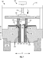
FIG. 7 provides a schematic cross-sectional view of yet anotherexample compaction system 100 in the process of compacting a laminate 200 according to an example embodiment of the present subject matter. Thecompaction system 100 ofFIG. 7 is configured in a similar manner as thecompaction system 100 ofFIG. 3 except as provided below. - For this embodiment, the
compaction system 100 includes apress system 170. Thepress system 170 includes abridge 172 removably coupled with or fixed to thetool 112. Thebridge 172 can be fixed to other structures as well. Thepress system 170 also includes aleadscrew 174 that is threadingly engaged with a cross bar of thebridge 172 as shown inFIG. 7 . Theleadscrew 174 can be rotated so that apress 176 of theleadscrew 174 engages theplunger 150. In this way, theplunger 150 can be moved toward the laminate 200 along the first direction D1. Theplunger 150 can engage thenoodle ring 120 and apply a force F1 thereto. The force F1 applied to thenoodle ring 120 by theplunger 150 causes thenoodle ring 120 to drive or compact thenoodle 230 into thecavity 220 defined by thelaminate 200. Theleadscrew 174 can be driven or torqued manually by an operator or in automated manner by a torque system, such as an electric motor. Theleadscrew 174 can be rotated in the opposite direction to move thepress 176 away from theplunger 150 after a compaction cycle or when compaction is complete. -
FIG. 8 provides a schematic cross-sectional view of afurther compaction system 100 in the process of compacting a laminate 200 according to an example embodiment of the present subject matter. Thecompaction system 100 ofFIG. 8 is configured in a similar manner as thecompaction system 100 ofFIG. 3 except as provided below. - For this embodiment, the
compaction system 100 includes apress system 170 having amandrel 178 and abolt 179 threadingly received within themandrel 178. As depicted, themandrel 178 is received within an opening defined by theplunger 150. Thebolt 179 can be a cap screw bolt, for example. Thebolt 179 can be rotated within themandrel 178 so that theplunger 150 is moved toward the laminate 200 along the first direction D1. Theplunger 150 can engage thenoodle ring 120 and apply a force F1 thereto. The force F1 applied to thenoodle ring 120 by theplunger 150 causes thenoodle ring 120 to drive or compact thenoodle 230 into thecavity 220 defined by thelaminate 200. Thebolt 179 can be driven or torqued manually by an operator or in automated manner by a torque system, such as an electric motor. Thebolt 179 can be rotated in the opposite direction to reduce the force F1 that theplunger 150 applies to thenoodle ring 120, e.g., after a compaction cycle or when compaction is complete. -
FIG. 9 provides a schematic cross-sectional view of a furtherexample compaction system 100 in the process of compacting a laminate 200 according to an example embodiment of the present subject matter. Thecompaction system 100 ofFIG. 9 is configured in a similar manner as thecompaction system 100 ofFIG. 3 except as provided below. - For this embodiment, the
compaction system 100 includes apiston system 180 for compacting thelaminate 200. As shown, thepiston system 180 includes apiston housing 182 defining apiston chamber 184. Thepiston housing 182 can form a part of a bridge, such as thebridge 172 ofFIG. 7 . Apiston 186 is received within thepiston chamber 184 of thepiston housing 182 and is movable, e.g., along the first direction D1. Apiston rod 188 is coupled with thepiston 186. Thepiston rod 188 extends between a first end and a second end, e.g., along the first direction D1. The first end of thepiston rod 188 is coupled with thepiston 186. Thepiston rod 188 is coupled with theplunger 150 at its second end. Accordingly, when thepiston 186 is moved within thepiston chamber 184, theplunger 150 is likewise moved. - The
piston 186 is hydraulically controlled in this example embodiment. It will be appreciated that thepiston 186 can be controlled in other suitable manners as well. As depicted, thepiston housing 182 defines afirst inlet 181 and afirst drain 183 that provide an ingress and an egress for working fluid WF to flow into and out of a first side S1 of thepiston chamber 184. Thepiston housing 182 also defines asecond inlet 185 and asecond drain 187 that provide an ingress and an egress for working fluid WF to flow into and out of a second side S2 of thepiston chamber 184. The first and second sides S1, S2 of thepiston chamber 184 are fluidly separated by thepiston 186. Thepiston system 180 includes acontrol valve 190 for controlling the flow of working fluid WF to thepiston chamber 184. For this example embodiment, the control valve is a three-way valve. - A
controller 192 communicatively coupled with thecontrol valve 190 can control thecontrol valve 190 to selectively allow working fluid WF to flow from afluid source 194 to the first side S1 of thepiston chamber 184 and to prevent working fluid WF from flowing to the second side S2 of thepiston chamber 184. Thecontroller 192 can include one or more processors and one or more memory devices. The one or more memory devices can include a non-transitory computer readable storage medium, for example. The one or more memory devices can store information accessible by the one or more processors, including computer-readable instructions that can be executed by the one or more processors. The instructions can be any set of instructions that, when executed by the one or more processors, cause the one or more processors to perform operations, such as controlling thecontrol valve 190. Thecontroller 192 can be configured as shown inFIG. 12 and described in the accompanying text. - By supplying working fluid WF to the first side S1 of the
piston chamber 184 and preventing working fluid from flowing to the second side S2, thepiston 186 can be moved downward toward the laminate 200 along the first direction D1. Thecontroller 192 can also control thecontrol valve 190 to selectively allow working fluid WF to flow from thefluid source 194 to the second side S2 of thepiston chamber 184 and to prevent working fluid WF from flowing to the first side S1 of thepiston chamber 184. By supplying working fluid WF to the second side S2 of thepiston chamber 184 and preventing working fluid from flowing to the first side S1, thepiston 186 can be moved upward away from the laminate 200 along the first direction D1. - A sensor 196 (e.g., a pressure sensor) can be positioned within or attached to the
noodle ring 120. Thesensor 196 can be communicatively coupled with thecontroller 192 and can provide feedback signals indicating the applied pressure placed on thenoodle ring 120 by theplunger 150. Thecontroller 192 can control thecontrol valve 190, and thus the flow of working fluid WF to thepiston chamber 184, based at least in part on the received feedback signals. -
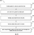
FIG. 10 provides a flow diagram of a method (400) of compacting a laminate according to an exemplary embodiment of the present subject matter. Any of the example compaction systems provided herein can be used to compact a laminate using method (400). Other compaction systems can be used to compact a laminate using method (400) as well. - At (402), the method (400) includes positioning a laminate on a tool of a compaction system. The laminate positioned on the tool can formed of one or more plies. The laminate can be positioned on the tool by laying up the plies of the laminate directly on the tool or the laminate can be laid up elsewhere and subsequently positioned on the tool. Further, the laminate can define a cavity. In some instances, the laminate is laid up in such a way that the laminate defines a cavity. For instance,
FIG. 3 depicts anexample laminate 200 positioned on thetool 112 of thecompaction system 100. As illustrated, the laminate 200 definescavity 220. Thecavity 220 is defined between thefirst section 210 and thesecond section 212 of the laminate 200 at thejoint interface 218. - At (404), the method (400) optionally includes shaping the cavity of the laminate to a desired shape. For instance, shaping the cavity of the laminate to the desired shape can include pressing a shaping tool into the cavity of the laminate to shape the cavity. The shaping tool can be mounted to the plunger of the compaction system, for example.
- By way of example,
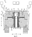
FIG. 11 provides a schematic cross-sectional view of acompaction system 100 in the process of shaping acavity 220 of a laminate 200 to a desired shape. As depicted, ashaping tool 152 is mounted to theplunger 150. For instance, theplunger 150 can include a chuck that holds theshaping tool 152. Theshaping tool 152 includes a shaping end 154 that is shaped complementary to the desired shape of thecavity 220. To achieve the desired geometry of thecavity 220, theplunger 150 with theshaping tool 152 mounted thereto can be moved toward the laminate 200 along the first direction D1. Theplunger 150 can be moved along the first direction D1 in any suitable manner, e.g., by tighteningbolts 160 as shown inFIG. 11 . Theplunger 150 can move the shaping end 154 of theshaping tool 152 into thecavity 220. In this way, the shaping end 154 of theshaping tool 152 can shape thecavity 220 by pressing on thelaminate 200. For instance, inFIG. 11 , the shaping end 154 can press on thefirst section 210 and thesecond section 212 to form thecavity 220 to the desired geometry so that a noodle can be positioned therein. - In some implementations, optionally, the method (400) can include inserting a slurry into the cavity prior to the noodle being compacted into the cavity. The slurry can be composed of a matrix material, such as a ceramic matrix material. The inserted slurry composition may facilitate a more complete filling of the cavity, which may lead to improved mechanical properties of the finished component.
- At (406), the method (400) includes positioning a noodle relative to or in the cavity. The noodle is positioned relative to or in the cavity so that the noodle is received within the cavity during the compaction process. In some implementations, the noodle is positioned such that at least a portion of the noodle is positioned within the cavity. For instance, as shown in
FIG. 3 ,noodle 230 is shown positioned in thecavity 220 of the laminate 200. The noodle can be formed of any suitable material, such as a CMC material. The noodle can be positioned manually by an operator or automatically, e.g., by a piston-controlled noodle insertion tool. For instance, a noodle insertion tool can be mounted to theplunger 150 of thecompaction system 100 ofFIG. 9 . For instance, a chuck of theplunger 150 can hold the noodle insertion tool. The noodle can be mounted to the noodle insertion tool. Theplunger 150 can be controlled to move toward the laminate 200 along the first direction D1 by thecontroller 192. The noodle insertion tool can position thenoodle 230 relative to thecavity 220. - At (408), the method (400) includes positioning a noodle ring relative to the noodle. For instance, in some implementations, the noodle ring can be positioned directly on the noodle. In other implementations, a sheet or film can be placed between the noodle ring and the noodle. For example,
protective sheet 132 is shown positioned between thenoodle ring 120 and thenoodle 230, e.g., along the first direction D1. In some implementations, the noodle ring is formed as a single component. In other implementations, the noodle ring is formed of at least two sections. - In some implementations, with the
noodle ring 120 positioned in place, optionally, a band debulk cap can be secured in place by a latch system to retain thenoodle ring 120 in place during compaction, e.g., as shown inFIG. 3 . In other implementations, thenoodle ring 120 can include a main body and one or more stabilizing members extending outward from the main body, e.g., as shown inFIG. 5 . The stabilizing members can be mounted to the tool upon which the laminate is positioned, for example. In some implementations, the main body includes at least one pair of stabilizing members that extend in opposite directions from the main body. The main body can have an outline or cross section shaped complementary to the noodle. The noodle ring can be coupled with the tool via one or more fasteners extending through openings in the stabilizing members and corresponding openings in the tool, e.g., as shown inFIG. 5 . - The noodle ring can be positioned manually by an operator. In some implementations, the noodle ring defines a hollow interior, includes a look-through window, and/or is transparent in whole or in part. Such features may allow an operator to see the laminate while positioning the noodle ring relative to the noodle. This can prevent damage to the laminate. Furthermore, in some implementations, the noodle ring can be positioned automatically, e.g., by a piston-controlled plunger with a noodle ring positioning tool mounted thereto. The noodle ring can be mounted to the noodle ring positioning tool and can be released by the tool when the noodle ring is positioned relative to the noodle.
- In some further implementations, as noted, the noodle ring can be formed in sections. In such implementations, the sections of the noodle ring can be moved into place or positioned relative to the noodle by an automated system at a non-vertical angle, e.g., at a forty-five degree angle relative to the first direction D1. For instance, an
automated system 155 is shown inFIG. 11 . Theautomated system 155 can include one or morerobotic arms 156 or other suitable devices. In this example embodiment, therobotic arms 156 can move a first section SC1 and a second section SC2 of thenoodle ring 120 in place. The first and second sections SC1, SC2 can form respective halves of thenoodle ring 120. Therobotic arms 156 can be controlled by acontroller 192, for example. Thecontroller 192 can be configured as shown inFIG. 12 and described in the accompanying text. Positioning the sections SC1, SC2 of thenoodle ring 120 at a non-vertical angle relative to the first direction D1 can prevent the noodle ring from crushing or otherwise damaging theprotruding portion 222 of the laminate 200. In some implementations, the sections SC1, SC2 of thenoodle ring 120 are positioned or moved toward the laminate 200 by at least a fifteen degree offset relative to the first direction D1 and at least a fifteen degree offset relative to the second direction D2. - At (410), the method (400) includes moving a plunger to apply a force on the noodle ring so that the noodle ring compacts the noodle into the cavity. For instance, a plunger of the compaction system can be moved toward the laminate. The plunger can be moved by any suitable system, mechanism, or device. For instance, in some implementations, the
plunger 150 can be moved by tightening one ormore bolts 160 as shown inFIG. 3 . In some implementations, theplunger 150 can be moved by apress system 170 as shown inFIG. 7 . In some implementations, theplunger 150 can be moved by apiston system 180 as shown inFIG. 9 . In some implementations, theplunger 150 can be moved by other suitable mechanical systems, e.g., as represented inFIG. 6 . For instance, theplunger 150 can be a plate movable by a jackscrew or an arbor press. - As shown in
FIG. 3 , theplunger 150 can be moved toward the laminate 200 along the first direction D1 and can engage thenoodle ring 120. With thenoodle ring 120 engaged, theplunger 150 applies a force F1 on thenoodle ring 120. Thenoodle ring 120 in turn applies a force on theprotective sheet 132, which in turn applies a force on thenoodle 230. The force on thenoodle 230 compacts thenoodle 230 into thecavity 220. In view of these applied forces, thenoodle 230 can be satisfactorily compacted into thecavity 220. Theplunger 150 can also engage theband debulk cap 130, which in turn can apply a force on theprotective sheet 132, which in turn can apply a force on the portion of thesecond section 212 that extends lengthwise along the second direction D2. - After compacting the laminate 200 and the
noodle 230 into thecavity 220 of the laminate 200, theplunger 150 can be moved away from the laminate 200 along the first direction D1. The laminate can be removed from thetool 112 and the compaction process can be repeated with subsequent laminates. -
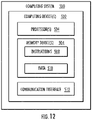
FIG. 12 provides a block diagram of anexample computing system 500 that can be used to implement methods and systems described herein according to example embodiments of the present subject. Thecomputing system 500 is one example of a suitable computing system for implementing the computing elements described herein. - As shown in
FIG. 12 , thecomputing system 500 can include one more computing device(s) 502. The controllers described herein can be embodied as one of the computing device(s) 502. The one or more computing device(s) 502 can include one or more processor(s) 504 and one or more memory device(s) 506. The one or more processor(s) 504 can include any suitable processing device, such as a microprocessor, microcontroller, integrated circuit, logic device, or other suitable processing device. The one or more memory device(s) 506 can include one or more computer-readable medium, including, but not limited to, non-transitory computer-readable medium or media, RAM, ROM, hard drives, flash drives, and other memory devices, such as one or more buffer devices. - The one or more memory device(s) 506 can store information accessible by the one or more processor(s) 504, including computer-
readable instructions 508 that can be executed by the one or more processor(s) 504. Theinstructions 508 can be any set of instructions that, when executed by the one or more processor(s) 504, cause the one or more processor(s) 504 to perform operations. Theinstructions 508 can be software written in any suitable programming language or can be implemented in hardware. Theinstructions 508 can be any of the computer-readable instructions noted herein. - The memory device(s) 506 can further store
data 510 that can be accessed by the processor(s) 504. For example, thedata 510 can include one or more table(s), function(s), algorithm(s), model(s), equation(s), etc. according to example embodiments of the present disclosure. - The one or more computing device(s) 502 can also include a
communication interface 512 used to communicate, for example, with other components of thecompaction system 100 or other systems or devices. Thecommunication interface 512 can include any suitable components for interfacing with one or more network(s), including for example, transmitters, receivers, ports, controllers, antennas, or other suitable components. - Although the figures and the accompanying text disclose exemplary systems and methods for compacting composite components, such as CMC and PMC components, the systems and methods disclosed herein are applicable to compacting other types of components as well.
- This written description uses examples to disclose the invention, including the best mode, and also to enable any person skilled in the art to practice the invention, including making and using any devices or systems and performing any incorporated methods. The patentable scope of the invention is defined by the claims and may include other examples that occur to those skilled in the art. Such other examples are intended to be within the scope of the claims if they include structural elements that do not differ from the literal language of the claims or if they include equivalent structural elements with insubstantial differences from the literal language of the claims.
- Further aspects of the invention are provided by the subject matter of the following clauses:
- 1. A method, comprising: positioning a laminate formed of plies on a tool of a compaction system, the laminate defining a cavity; positioning a noodle relative to or in the cavity; positioning a noodle ring relative to the noodle; and moving a plunger to apply a force on the noodle ring so that the noodle ring compacts the noodle into the cavity.
- 2. The method of any preceding clause, further comprising: pressing a shaping tool mounted to the plunger into the cavity of the laminate to shape the cavity.
- 3. The method of any preceding clause, wherein the laminate has a first section and a second section, wherein the first section extends lengthwise along a first direction and at least a portion of the second section extends lengthwise along the first direction and at least a portion of the second section extends lengthwise along a second direction that is substantially orthogonal to the first direction, and wherein the cavity is defined between the first section and the second section where the second section transitions from extending lengthwise along the first direction to extending lengthwise along the second direction.
- 4. The method of any preceding clause, wherein the noodle ring defines a hollow interior.
- 5. The method of any preceding clause, wherein the noodle ring has a look-through window.
- 6. The method of any preceding clause, wherein the noodle ring is at least in part transparent.
- 7. The method of any preceding clause, further comprising: positioning a protective sheet between the noodle and the noodle ring.
- 8. The method of any preceding clause, wherein the noodle ring has a cross section shaped complementary to a cross section of the noodle.
- 9. The method of any preceding clause, further comprising: inserting a slurry into the cavity prior to the noodle being compacted into the cavity.
- 10. The method of any preceding clause, wherein the noodle ring has a main body and a first stabilizing member extending outward from the main body and coupling the noodle ring to at least one of a band debulk cap and the tool, the main body having a cross section shaped complementary to a cross section of the noodle.
- 11. The method of any preceding clause, wherein the noodle ring has a second stabilizing member extending outward from the main body and coupling the noodle ring to at least one of the band debulk cap and the tool.
- 12. The method of any preceding clause, wherein the first stabilizing member and the second stabilizing member extend outward from the main body in opposite directions.
- 13. The method of any preceding clause, wherein the noodle ring is formed of at least two sections.
- 14. The method of any preceding clause, wherein the at least two sections of the noodle ring are positioned by an automated system relative to the noodle at a non-vertical angle.
- 15. The method of any preceding clause, wherein the plunger is moved by a press system, the press system having a bridge coupled with the tool and a leadscrew threadingly engaged with the bridge, the leadscrew having a press that engages the plunger.
- 16. The method of any preceding clause, wherein the plunger is moved by a piston system, the piston system having a piston housing defining a piston chamber and a piston movable within the piston chamber, the piston being coupled with the plunger via a piston rod, and wherein when the piston is moved within the piston chamber, the plunger is moved in unison with the piston.
- 17. A method, comprising: positioning a laminate on a tool of a compaction system, the laminate having a first section and a second section each formed of one or more plies, the laminate defining a cavity at a location where the first section and the second section diverge; positioning at least a portion of a noodle in the cavity; positioning a noodle ring relative to the noodle, the noodle ring having a cross section shaped complementary to a cross section of the noodle; and moving a plunger to apply a force on the noodle ring so that the noodle ring compacts the noodle into the cavity.
- 18. The method of any preceding clause, wherein a protruding portion of the first section of the laminate overlaps with the noodle ring along a first direction.
- 19. The method of any preceding clause, further comprising: positioning a band debulk cap relative to the tool and the noodle ring, the band debulk cap defining a spring chamber in which a spring is received, the spring being connected to the band debulk cap and engaged with the plunger for biasing the plunger away from the laminate.
- 20. A method, comprising: positioning a laminate on a tool of a compaction system, the laminate defining a cavity; positioning at least a portion of a noodle in the cavity; positioning a noodle ring relative to the noodle; coupling the noodle ring to the tool; and applying a force on the noodle ring so that the noodle is compacted into the cavity.
Claims (15)
- A method, comprising:positioning a laminate formed of plies on a tool of a compaction system, the laminate defining a cavity;positioning a noodle relative to or in the cavity;positioning a noodle ring relative to the noodle; andmoving a plunger to apply a force on the noodle ring so that the noodle ring compacts the noodle into the cavity.
- The method of any preceding claim, further comprising:
pressing a shaping tool mounted to the plunger into the cavity of the laminate to shape the cavity. - The method of any preceding claim, wherein the laminate has a first section and a second section, wherein the first section extends lengthwise along a first direction and at least a portion of the second section extends lengthwise along the first direction and at least a portion of the second section extends lengthwise along a second direction that is substantially orthogonal to the first direction, and wherein the cavity is defined between the first section and the second section where the second section transitions from extending lengthwise along the first direction to extending lengthwise along the second direction.
- The method of any preceding claim, wherein the noodle ring defines a hollow interior, has a look-through window, and/or is at least in part transparent.
- The method of any preceding claim, further comprising:
positioning a protective sheet between the noodle and the noodle ring. - The method of any preceding claim, wherein the noodle ring has a cross section shaped complementary to a cross section of the noodle.
- The method of any preceding claim, further comprising:
inserting a slurry into the cavity prior to the noodle being compacted into the cavity. - The method of any preceding claim, wherein the noodle ring has a main body and a first stabilizing member extending outward from the main body and coupling the noodle ring to at least one of a band debulk cap and the tool, the main body having a cross section shaped complementary to a cross section of the noodle.
- The method of claim 8, wherein the noodle ring has a second stabilizing member extending outward from the main body and coupling the noodle ring to at least one of the band debulk cap and the tool.
- The method of claim 9, wherein the first stabilizing member and the second stabilizing member extend outward from the main body in opposite directions.
- The method of any preceding claim, wherein the noodle ring is formed of at least two sections, wherein the at least two sections of the noodle ring are positioned by an automated system relative to the noodle at a non-vertical angle.
- The method of any preceding claim, wherein the plunger is moved by a press system, the press system having a bridge coupled with the tool and a leadscrew threadingly engaged with the bridge, the leadscrew having a press that engages the plunger.
- The method of any preceding claim, wherein the plunger is moved by a piston system, the piston system having a piston housing defining a piston chamber and a piston movable within the piston chamber, the piston being coupled with the plunger via a piston rod, and wherein when the piston is moved within the piston chamber, the plunger is moved in unison with the piston.
- A method, comprising:positioning a laminate on a tool of a compaction system, the laminate having a first section and a second section each formed of one or more plies, the laminate defining a cavity at a location where the first section and the second section diverge;positioning at least a portion of a noodle in the cavity;positioning a noodle ring relative to the noodle, the noodle ring having a cross section shaped complementary to a cross section of the noodle; andmoving a plunger to apply a force on the noodle ring so that the noodle ring compacts the noodle into the cavity.
- A method, comprising:positioning a laminate on a tool of a compaction system, the laminate defining a cavity;positioning at least a portion of a noodle in the cavity;positioning a noodle ring relative to the noodle;coupling the noodle ring to the tool; andapplying a force on the noodle ring so that the noodle is compacted into the cavity.
Applications Claiming Priority (1)
| Application Number | Priority Date | Filing Date | Title |
|---|---|---|---|
| US17/166,223 US11504930B2 (en) | 2021-02-03 | 2021-02-03 | Compaction system and methods for compacting composite components |
Publications (2)
| Publication Number | Publication Date |
|---|---|
| EP4039454A1 true EP4039454A1 (en) | 2022-08-10 |
| EP4039454B1 EP4039454B1 (en) | 2025-09-03 |
Family
ID=80112213
Family Applications (1)
| Application Number | Title | Priority Date | Filing Date |
|---|---|---|---|
| EP22151476.3A Active EP4039454B1 (en) | 2021-02-03 | 2022-01-13 | Compaction system and methods for compacting composite components |
Country Status (3)
| Country | Link |
|---|---|
| US (2) | US11504930B2 (en) |
| EP (1) | EP4039454B1 (en) |
| CN (1) | CN114851102B (en) |
Families Citing this family (3)
| Publication number | Priority date | Publication date | Assignee | Title |
|---|---|---|---|---|
| US12134583B2 (en) * | 2021-08-12 | 2024-11-05 | Rtx Corporation | Particle based inserts for CMC |
| US12194691B2 (en) | 2022-11-10 | 2025-01-14 | Rolls-Royce Plc | Method of debulking of ceramic matrix composite prepreg material |
| US12435640B2 (en) * | 2023-11-02 | 2025-10-07 | Rtx Corporation | Gas turbine engine vane outer diameter platform integrated with blade outer air seal |
Citations (3)
| Publication number | Priority date | Publication date | Assignee | Title |
|---|---|---|---|---|
| EP2489498A1 (en) * | 2009-10-16 | 2012-08-22 | Toray Industries, Inc. | Method and device for manufacturing beam member |
| EP2902179A2 (en) * | 2014-02-04 | 2015-08-05 | The Boeing Company | Radius filler and method of manufacturing same |
| US20190224938A1 (en) * | 2018-01-24 | 2019-07-25 | General Electric Company | Composite Components Having T or L-Joints and Methods for Forming Same |
Family Cites Families (21)
| Publication number | Priority date | Publication date | Assignee | Title |
|---|---|---|---|---|
| US1554497A (en) | 1924-07-07 | 1925-09-22 | C A Webster | Means for making alpha laminated wood product |
| US2057466A (en) | 1934-06-16 | 1936-10-13 | Hartford Empire Co | Method of and apparatus for molding refractory blocks and the like |
| US2139542A (en) | 1936-07-30 | 1938-12-06 | Celanese Corp | Treatment of textile materials |
| CH405892A (en) | 1963-05-21 | 1966-01-15 | Buehler Ag Geb | Clamping device for a stack of sieve frames |
| US3438836A (en) | 1966-06-06 | 1969-04-15 | Farnam Co F D | Apparatus for forming laminates |
| US7186367B2 (en) | 2004-05-13 | 2007-03-06 | The United States Of America As Represented By The Administrator Of The National Aeronautics And Space Administration | Double vacuum bag process for resin matrix composite manufacturing |
| US7501034B2 (en) * | 2004-10-15 | 2009-03-10 | The Procter & Gamble Company | Method for producing a corrugated stretch laminate |
| WO2008109029A2 (en) | 2007-03-01 | 2008-09-12 | Cumings Robert C | Composite article debulking process |
| US8307872B2 (en) | 2008-11-13 | 2012-11-13 | The Boeing Company | Apparatus for curing a composite structural member |
| DE102009001075A1 (en) * | 2009-02-23 | 2010-09-09 | Airbus Deutschland Gmbh | Method for at least partially reworking or replacing a stiffening element of a fiber composite structure and associated attachment device |
| US8997642B2 (en) | 2011-08-08 | 2015-04-07 | The Boeing Company | Method for transporting, placing and compacting composite stiffeners |
| US9103214B2 (en) * | 2011-08-23 | 2015-08-11 | United Technologies Corporation | Ceramic matrix composite vane structure with overwrap for a gas turbine engine |
| US9422815B2 (en) * | 2012-02-15 | 2016-08-23 | United Technologies Corporation | Gas turbine engine component with compound cusp cooling configuration |
| EP3102329B1 (en) * | 2014-02-05 | 2018-10-10 | Talis Biomedical Corporation | Sample preparation module with stepwise pressurization mechanism |
| US9370922B1 (en) * | 2014-03-18 | 2016-06-21 | The Boeing Company | Systems and methods for stretch-forming multi-thickness composite skins |
| US20170029577A1 (en) * | 2015-07-29 | 2017-02-02 | The Boeing Company | Noodle Comprised of a Matrix of Discontinuous Filaments |
| US11104113B2 (en) * | 2017-04-19 | 2021-08-31 | The Boeing Company | Systems and methods for assembling elongate composite structures |
| US11958217B2 (en) * | 2017-10-09 | 2024-04-16 | General Electric Company | Systems and methods for compacting composite components |
| US11242866B2 (en) * | 2018-08-01 | 2022-02-08 | General Electric Company | Casing having a non-axisymmetric composite wall |
| US10724387B2 (en) * | 2018-11-08 | 2020-07-28 | Raytheon Technologies Corporation | Continuation of a shear tube through a vane platform for structural support |
| US11472087B2 (en) * | 2019-03-25 | 2022-10-18 | The Boeing Company | Composite radius filler manufacturing methods and related systems |
-
2021
- 2021-02-03 US US17/166,223 patent/US11504930B2/en active Active
-
2022
- 2022-01-13 EP EP22151476.3A patent/EP4039454B1/en active Active
- 2022-02-07 CN CN202210115705.2A patent/CN114851102B/en active Active
- 2022-11-09 US US17/983,483 patent/US11840041B2/en active Active
Patent Citations (3)
| Publication number | Priority date | Publication date | Assignee | Title |
|---|---|---|---|---|
| EP2489498A1 (en) * | 2009-10-16 | 2012-08-22 | Toray Industries, Inc. | Method and device for manufacturing beam member |
| EP2902179A2 (en) * | 2014-02-04 | 2015-08-05 | The Boeing Company | Radius filler and method of manufacturing same |
| US20190224938A1 (en) * | 2018-01-24 | 2019-07-25 | General Electric Company | Composite Components Having T or L-Joints and Methods for Forming Same |
Also Published As
| Publication number | Publication date |
|---|---|
| US20230076472A1 (en) | 2023-03-09 |
| CN114851102A (en) | 2022-08-05 |
| CN114851102B (en) | 2025-11-07 |
| EP4039454B1 (en) | 2025-09-03 |
| US20220242079A1 (en) | 2022-08-04 |
| US11504930B2 (en) | 2022-11-22 |
| US11840041B2 (en) | 2023-12-12 |
Similar Documents
| Publication | Publication Date | Title |
|---|---|---|
| US11840041B2 (en) | Compaction system and methods for compacting composite components | |
| US20220356815A1 (en) | Shroud for a gas turbine engine | |
| EP3421233A1 (en) | Methods for shaping composite ply layups | |
| EP3517282B1 (en) | Composite component having t or l-joints and method for forming same | |
| CN104100304B (en) | Turbine blade component | |
| EP3620618B1 (en) | Grommet for a turbine engine | |
| US11035239B2 (en) | Ceramic matrix composite turbine nozzle shell and method of assembly | |
| US20180200967A1 (en) | Method and tooling for forming a flange of a composite component | |
| US20190040742A1 (en) | Ceramic matrix composite airfoil repair | |
| US20200080425A1 (en) | CMC Component Cooling Cavities | |
| US10724390B2 (en) | Collar support assembly for airfoils | |
| CA2945244C (en) | Fabrication of gas turbine engine components using multiple processing steps | |
| US10502074B2 (en) | Methods and assemblies for forming features in composite components | |
| CN110886625B (en) | Method of forming CMC component cooling cavity | |
| US20230029918A1 (en) | Frangible airfoil with shape memory alloy | |
| US11958217B2 (en) | Systems and methods for compacting composite components | |
| US20160130950A1 (en) | Gas turbine engine component with rib support |
Legal Events
| Date | Code | Title | Description |
|---|---|---|---|
| PUAI | Public reference made under article 153(3) epc to a published international application that has entered the european phase |
Free format text: ORIGINAL CODE: 0009012 |
|
| STAA | Information on the status of an ep patent application or granted ep patent |
Free format text: STATUS: THE APPLICATION HAS BEEN PUBLISHED |
|
| AK | Designated contracting states |
Kind code of ref document: A1 Designated state(s): AL AT BE BG CH CY CZ DE DK EE ES FI FR GB GR HR HU IE IS IT LI LT LU LV MC MK MT NL NO PL PT RO RS SE SI SK SM TR |
|
| STAA | Information on the status of an ep patent application or granted ep patent |
Free format text: STATUS: REQUEST FOR EXAMINATION WAS MADE |
|
| 17P | Request for examination filed |
Effective date: 20230209 |
|
| RBV | Designated contracting states (corrected) |
Designated state(s): AL AT BE BG CH CY CZ DE DK EE ES FI FR GB GR HR HU IE IS IT LI LT LU LV MC MK MT NL NO PL PT RO RS SE SI SK SM TR |
|
| GRAP | Despatch of communication of intention to grant a patent |
Free format text: ORIGINAL CODE: EPIDOSNIGR1 |
|
| STAA | Information on the status of an ep patent application or granted ep patent |
Free format text: STATUS: GRANT OF PATENT IS INTENDED |
|
| GRAJ | Information related to disapproval of communication of intention to grant by the applicant or resumption of examination proceedings by the epo deleted |
Free format text: ORIGINAL CODE: EPIDOSDIGR1 |
|
| STAA | Information on the status of an ep patent application or granted ep patent |
Free format text: STATUS: REQUEST FOR EXAMINATION WAS MADE |
|
| RIC1 | Information provided on ipc code assigned before grant |
Ipc: F01D 5/28 20060101ALN20250306BHEP Ipc: B29L 31/08 20060101ALN20250306BHEP Ipc: B29L 31/00 20060101ALN20250306BHEP Ipc: B29C 43/02 20060101ALN20250306BHEP Ipc: B29C 70/82 20060101ALN20250306BHEP Ipc: B29C 70/40 20060101ALN20250306BHEP Ipc: B29C 70/34 20060101ALN20250306BHEP Ipc: F01D 9/04 20060101ALI20250306BHEP Ipc: F01D 25/00 20060101ALI20250306BHEP Ipc: B32B 5/26 20060101ALI20250306BHEP Ipc: B32B 3/08 20060101ALI20250306BHEP Ipc: B29D 99/00 20100101ALI20250306BHEP Ipc: B29C 70/86 20060101ALI20250306BHEP Ipc: B29C 70/68 20060101ALI20250306BHEP Ipc: B29C 70/54 20060101ALI20250306BHEP Ipc: B29C 65/00 20060101ALI20250306BHEP Ipc: B29C 70/24 20060101AFI20250306BHEP |
|
| GRAP | Despatch of communication of intention to grant a patent |
Free format text: ORIGINAL CODE: EPIDOSNIGR1 |
|
| STAA | Information on the status of an ep patent application or granted ep patent |
Free format text: STATUS: GRANT OF PATENT IS INTENDED |
|
| RIC1 | Information provided on ipc code assigned before grant |
Ipc: F01D 5/28 20060101ALN20250401BHEP Ipc: B29L 31/08 20060101ALN20250401BHEP Ipc: B29L 31/00 20060101ALN20250401BHEP Ipc: B29C 43/02 20060101ALN20250401BHEP Ipc: B29C 70/82 20060101ALN20250401BHEP Ipc: B29C 70/40 20060101ALN20250401BHEP Ipc: B29C 70/34 20060101ALN20250401BHEP Ipc: F01D 9/04 20060101ALI20250401BHEP Ipc: F01D 25/00 20060101ALI20250401BHEP Ipc: B32B 5/26 20060101ALI20250401BHEP Ipc: B32B 3/08 20060101ALI20250401BHEP Ipc: B29D 99/00 20100101ALI20250401BHEP Ipc: B29C 70/86 20060101ALI20250401BHEP Ipc: B29C 70/68 20060101ALI20250401BHEP Ipc: B29C 70/54 20060101ALI20250401BHEP Ipc: B29C 65/00 20060101ALI20250401BHEP Ipc: B29C 70/24 20060101AFI20250401BHEP |
|
| INTG | Intention to grant announced |
Effective date: 20250411 |
|
| GRAS | Grant fee paid |
Free format text: ORIGINAL CODE: EPIDOSNIGR3 |
|
| GRAA | (expected) grant |
Free format text: ORIGINAL CODE: 0009210 |
|
| STAA | Information on the status of an ep patent application or granted ep patent |
Free format text: STATUS: THE PATENT HAS BEEN GRANTED |
|
| AK | Designated contracting states |
Kind code of ref document: B1 Designated state(s): AL AT BE BG CH CY CZ DE DK EE ES FI FR GB GR HR HU IE IS IT LI LT LU LV MC MK MT NL NO PL PT RO RS SE SI SK SM TR |
|
| RAP3 | Party data changed (applicant data changed or rights of an application transferred) |
Owner name: GENERAL ELECTRIC COMPANY |
|
| REG | Reference to a national code |
Ref country code: CH Ref legal event code: EP |
|
| REG | Reference to a national code |
Ref country code: DE Ref legal event code: R096 Ref document number: 602022020507 Country of ref document: DE |
|
| P01 | Opt-out of the competence of the unified patent court (upc) registered |
Free format text: CASE NUMBER: UPC_APP_5474_4039454/2025 Effective date: 20250901 |
|
| REG | Reference to a national code |
Ref country code: IE Ref legal event code: FG4D |
|
| REG | Reference to a national code |
Ref country code: NL Ref legal event code: MP Effective date: 20250903 |
|
| PGFP | Annual fee paid to national office [announced via postgrant information from national office to epo] |
Ref country code: GB Payment date: 20251217 Year of fee payment: 5 |
|
| PG25 | Lapsed in a contracting state [announced via postgrant information from national office to epo] |
Ref country code: NO Free format text: LAPSE BECAUSE OF FAILURE TO SUBMIT A TRANSLATION OF THE DESCRIPTION OR TO PAY THE FEE WITHIN THE PRESCRIBED TIME-LIMIT Effective date: 20251203 |
|
| REG | Reference to a national code |
Ref country code: LT Ref legal event code: MG9D |
|
| PG25 | Lapsed in a contracting state [announced via postgrant information from national office to epo] |
Ref country code: FI Free format text: LAPSE BECAUSE OF FAILURE TO SUBMIT A TRANSLATION OF THE DESCRIPTION OR TO PAY THE FEE WITHIN THE PRESCRIBED TIME-LIMIT Effective date: 20250903 |
|
| PG25 | Lapsed in a contracting state [announced via postgrant information from national office to epo] |
Ref country code: HR Free format text: LAPSE BECAUSE OF FAILURE TO SUBMIT A TRANSLATION OF THE DESCRIPTION OR TO PAY THE FEE WITHIN THE PRESCRIBED TIME-LIMIT Effective date: 20250903 |
|
| PGFP | Annual fee paid to national office [announced via postgrant information from national office to epo] |
Ref country code: FR Payment date: 20251218 Year of fee payment: 5 |
|
| PG25 | Lapsed in a contracting state [announced via postgrant information from national office to epo] |
Ref country code: GR Free format text: LAPSE BECAUSE OF FAILURE TO SUBMIT A TRANSLATION OF THE DESCRIPTION OR TO PAY THE FEE WITHIN THE PRESCRIBED TIME-LIMIT Effective date: 20251204 |
|
| PG25 | Lapsed in a contracting state [announced via postgrant information from national office to epo] |
Ref country code: SE Free format text: LAPSE BECAUSE OF FAILURE TO SUBMIT A TRANSLATION OF THE DESCRIPTION OR TO PAY THE FEE WITHIN THE PRESCRIBED TIME-LIMIT Effective date: 20250903 |
|
| PG25 | Lapsed in a contracting state [announced via postgrant information from national office to epo] |
Ref country code: LV Free format text: LAPSE BECAUSE OF FAILURE TO SUBMIT A TRANSLATION OF THE DESCRIPTION OR TO PAY THE FEE WITHIN THE PRESCRIBED TIME-LIMIT Effective date: 20250903 |
|
| PG25 | Lapsed in a contracting state [announced via postgrant information from national office to epo] |
Ref country code: PL Free format text: LAPSE BECAUSE OF FAILURE TO SUBMIT A TRANSLATION OF THE DESCRIPTION OR TO PAY THE FEE WITHIN THE PRESCRIBED TIME-LIMIT Effective date: 20250903 Ref country code: BG Free format text: LAPSE BECAUSE OF FAILURE TO SUBMIT A TRANSLATION OF THE DESCRIPTION OR TO PAY THE FEE WITHIN THE PRESCRIBED TIME-LIMIT Effective date: 20250903 |
|
| PG25 | Lapsed in a contracting state [announced via postgrant information from national office to epo] |
Ref country code: RS Free format text: LAPSE BECAUSE OF FAILURE TO SUBMIT A TRANSLATION OF THE DESCRIPTION OR TO PAY THE FEE WITHIN THE PRESCRIBED TIME-LIMIT Effective date: 20251203 |
|
| PG25 | Lapsed in a contracting state [announced via postgrant information from national office to epo] |
Ref country code: ES Free format text: LAPSE BECAUSE OF FAILURE TO SUBMIT A TRANSLATION OF THE DESCRIPTION OR TO PAY THE FEE WITHIN THE PRESCRIBED TIME-LIMIT Effective date: 20250903 |
|
| REG | Reference to a national code |
Ref country code: AT Ref legal event code: MK05 Ref document number: 1832535 Country of ref document: AT Kind code of ref document: T Effective date: 20250903 |
|
| PG25 | Lapsed in a contracting state [announced via postgrant information from national office to epo] |
Ref country code: NL Free format text: LAPSE BECAUSE OF FAILURE TO SUBMIT A TRANSLATION OF THE DESCRIPTION OR TO PAY THE FEE WITHIN THE PRESCRIBED TIME-LIMIT Effective date: 20250903 |
|
| PG25 | Lapsed in a contracting state [announced via postgrant information from national office to epo] |
Ref country code: SM Free format text: LAPSE BECAUSE OF FAILURE TO SUBMIT A TRANSLATION OF THE DESCRIPTION OR TO PAY THE FEE WITHIN THE PRESCRIBED TIME-LIMIT Effective date: 20250903 |
|
| PGFP | Annual fee paid to national office [announced via postgrant information from national office to epo] |
Ref country code: DE Payment date: 20251217 Year of fee payment: 5 |
|
| PG25 | Lapsed in a contracting state [announced via postgrant information from national office to epo] |
Ref country code: AT Free format text: LAPSE BECAUSE OF FAILURE TO SUBMIT A TRANSLATION OF THE DESCRIPTION OR TO PAY THE FEE WITHIN THE PRESCRIBED TIME-LIMIT Effective date: 20250903 |
|
| PG25 | Lapsed in a contracting state [announced via postgrant information from national office to epo] |
Ref country code: IT Free format text: LAPSE BECAUSE OF FAILURE TO SUBMIT A TRANSLATION OF THE DESCRIPTION OR TO PAY THE FEE WITHIN THE PRESCRIBED TIME-LIMIT Effective date: 20250903 |
|
| PG25 | Lapsed in a contracting state [announced via postgrant information from national office to epo] |
Ref country code: IS Free format text: LAPSE BECAUSE OF FAILURE TO SUBMIT A TRANSLATION OF THE DESCRIPTION OR TO PAY THE FEE WITHIN THE PRESCRIBED TIME-LIMIT Effective date: 20260103 |
|
| PG25 | Lapsed in a contracting state [announced via postgrant information from national office to epo] |
Ref country code: PT Free format text: LAPSE BECAUSE OF FAILURE TO SUBMIT A TRANSLATION OF THE DESCRIPTION OR TO PAY THE FEE WITHIN THE PRESCRIBED TIME-LIMIT Effective date: 20260105 Ref country code: CZ Free format text: LAPSE BECAUSE OF FAILURE TO SUBMIT A TRANSLATION OF THE DESCRIPTION OR TO PAY THE FEE WITHIN THE PRESCRIBED TIME-LIMIT Effective date: 20250903 |
|
| PG25 | Lapsed in a contracting state [announced via postgrant information from national office to epo] |
Ref country code: EE Free format text: LAPSE BECAUSE OF FAILURE TO SUBMIT A TRANSLATION OF THE DESCRIPTION OR TO PAY THE FEE WITHIN THE PRESCRIBED TIME-LIMIT Effective date: 20250903 Ref country code: SK Free format text: LAPSE BECAUSE OF FAILURE TO SUBMIT A TRANSLATION OF THE DESCRIPTION OR TO PAY THE FEE WITHIN THE PRESCRIBED TIME-LIMIT Effective date: 20250903 |